US3597676A - Thermistor circuit for use in an angular movement sensing device - Google Patents
Thermistor circuit for use in an angular movement sensing device Download PDFInfo
- Publication number
- US3597676A US3597676A US830825A US3597676DA US3597676A US 3597676 A US3597676 A US 3597676A US 830825 A US830825 A US 830825A US 3597676D A US3597676D A US 3597676DA US 3597676 A US3597676 A US 3597676A
- Authority
- US
- United States
- Prior art keywords
- bridge
- thermistor
- thermistors
- voltage
- terminal
- Prior art date
- Legal status (The legal status is an assumption and is not a legal conclusion. Google has not performed a legal analysis and makes no representation as to the accuracy of the status listed.)
- Expired - Lifetime
Links
Images
Classifications
-
- G—PHYSICS
- G01—MEASURING; TESTING
- G01P—MEASURING LINEAR OR ANGULAR SPEED, ACCELERATION, DECELERATION, OR SHOCK; INDICATING PRESENCE, ABSENCE, OR DIRECTION, OF MOVEMENT
- G01P3/00—Measuring linear or angular speed; Measuring differences of linear or angular speeds
- G01P3/26—Devices characterised by the use of fluids
Definitions
- Smith ABSTRACT A circuit for measuring the difference in cooling imposed upon two thermistor-s, which circuit is particularly adapted for use in a sensing device wherein a fluid jet is deflected relative to the thermistors in response to angular movement, and comprises a bridge for electrically heating each thermistor and thus lowering its resistance until the bridge is balanced, and a difference in the power consumption required to maintain each thermistor at its equilibrium temperature is an indication of the unequal cooling imposed upon the thermistors, which, in a fluid-jet-type angular rate sensor, is an indication of the deflection of the fluid jet from a centered condition relative to the jets which is in turn an indication of the rate and direction of angular movement.
- the present invention relates to a circuit for heating and thereby adjusting the resistance of a pair of thermistors such as those in the fluid-jet-type angular movement sensing device forming the subject of application Ser. No. 632,239, which circuit is highly sensitive to minute variations in the cooling effect imposed upon the thermistors and has improved responsiveness or a minimum of lag or delay between an increment of turn and the response thereto by the unit.
- the electrical power required to maintain the thermistors at their equilibrium temperature is a function of the cooling imposed upon the thermistors, which is itself a function of the centered condition of the fluid jet relative to the thermistors.
- the deflection of the jet from the centered condition relative to the thermistors isin turn a function of the angular movement imposed upon the unit so that the power consumption thus provides an indication of the rate and the direction of the angular movement.
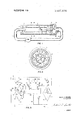
- FIG. 1 is a schematic illustration in section of a unit with which the circuit of this invention is adapted to be used.
- FIG 2 is a sectional vview taken substantially on the line 2-2 of FIG. 1.
- FIG. 3 is a circuit diagram of an electrical circuit in accordance with this invention. 7
- FIGS. 1 and 2 there is illustrated an angular rate sensor of the "fluid jet type in which there is provided an outer or housing sleeve 1 having a jet-enclosing or sensor sleeve 2 disposed internally of and coaxial with the housing 1, and disposed in spaced relation thereto to provide an annular space 3 between the same.
- the sensor sleeve 2 may be supported for example by means of braces 4 as shown.
- the housing sleeve 1 is closed at one end by a plug 5 having an axial bore in which is secured a nozzle 6.
- the nozzle 6 is aligned coaxially with the sensor sleeve 2 and is designed to discharge a jet of fluid into the sensor sleeve 2 at its input end externally of the housing sleeve 1,,the nozzle 6 is connected by a conduit 7 with the output ofa pump 8.
- the sensing means that is, the means upon which the fluid jet discharged from the nozzle 6 impinges.
- the response is generated by movement of the sensing means relative to the discharge end of the nozzle 6 during the period of time that an increment of fluid is in transit from the nozzle 6 to the sensing means.
- This relative motion is manifested by an impingement of that increment of fluid in a nonsymmetrical manner upon the sensing means.
- the amount of displacement of the fluid jet relative to the sensing means is proportional to the angular rate of movement and the device can accordingly be calibrated to indicate angular rate of movement.
- the sensing means in accordance with the embodiment of the invention'illustrated in FIGS. 1 and 2 comprises a pair of thermistors 9 carried by posts 10 at the free end 11 of a support 12.
- the support 12 is mounted in a plug 13 that closes the end of the housing sleeve 1 opposite from the plug 5 and is arrangedsubstantially.coaxially of the sensor sleeve 2 with its free end 11 extending into the sleeve 2.
- the free end 11 is preferably rounded to provide for a smooth flow of the jet thereover while the support 12 itself is sufficiently smaller in cross section than the inner diameter of the housing sleeve 1 to provide an annular space 14 between the two.
- There are exhaust ports 15 in the plug 13 to provide for escape from the housing sleeve 1 of the fluid delivered by the nozzle 6.
- the thermistors 9 are adapted to be heated by electrical power supplied through leads 16 that extend through the support 12 to the posts 10.
- the end of the housing sleeve 1 adjacent to the plug 13 may be closed by a cap 17 having an end wall that is spaced from the plug '13 and defines with the plug 13 a fluid chamber 18 that collects the exhaust fluid from the ports 15 and is connected by a coupling 19 and a conduit 20 to the intake of the pump 8.
- the leads 16 in this casemay be directed outwardly of the chamber 18 through an insulating plug 21 that seals the aperture in the cap 17 through which the leads 16 are run.
- the fluid stream is deflected to a nonsymmetrical impingement upon the two thermistors and produces an unequal cooling of them as the thermistors are cooled, their electrical resistance increases and their heating circuits are thus thrown out of balance.
- a measurement of the unequal power required to maintain the two thermistors at equilibrium temperature indicates the amount of deflection of the jet and, through the proportional relation of the deflection of the jet to the rate of angular movement, also indicates the rate of angular movement.
- the direction of angular movement is indicated by the relative cooling of the two thermistors, that is, increased cooling of the one bead indicates angular movement in the plane of sensitivity in the direction of the opposite bead.
- FIG. 3 there is illustrated schematically the electrical circuit for heating the thermistors 9 and for indicating the direction and rate of angular movement.
- the battery 50 represents a source of electrical powers, that is supplied to the circuit through a power lead 51 and a ground lead 52,
- On of the thermistors 9 is illustrated at 53 at the left in FIG. 3.
- the thermistor 53 is connected in one leg of a bridge 54 along with a resistor 55.
- the other leg of the bridge 54 consists of two resistors 56 and 57 that correspond respectively to the resistors 55 and the thermistor S3.
- the second of the thermistors 9 which thermistor 71 is connected in a circuit comparable to the circuit in which the thermistor S3 is connected, which circuit includes a bridge 72, a control transistor 73 and a power transistor 74.
- the connections and the function and operation of the circuit for the thermistor 71 is the same as that of the thermistor 53, the above description of the connections and the following description of the function and operation of the circuit for the thermistor 53 will also serve as descriptions applicable to the thermistor 71.
- the bridge circuit 54 is thus balanced and will remain in balance so long as the cooling imposed upon the thermistor is not changed.
- the power supplied to the thermistor S3 and the resulting heat are thus increased to reestablish the equilibrium temperature of the thermistor at the new and increased heat dissipation rate.
- the circuit has an opposite reaction.
- the output of the device which may be by way of a meter or a directly usable control signal, is taken by comparing the voltage at the input terminal 68 of the bridge 54 with that at the corresponding terminal of the bridge 72. As illustrated, this may be accomplished through an output transistor 75 having a base lead 76 connected through a resistor 77 to the input terminal 68 of the bridge 54.
- the collector lead 78 of the transistor 75 is connected to the power lead 51 through a resistor 79 while the emitter lead 80 is connected to the ground lead 52 through a resistor 81.
- the input terminal 84 of the bridge 72 is also connected to a comparable output transistor 82 at the base lead 83 thereof, which transistor 82 has its collector lead 85 connected to the power lead 51 through a resistor 86 and its emitter lead 87 connected to the power lead 52 through the resistor 81.
- the output, indicated at 88, is connected across the collector leads 78 and 85 of the transistors 75 and 82.
- a resistor 89 connected at its opposite ends to the base leads 77 and 83 of the output transistors 75 and 82.
- an adjustable resistor 90 that is adapted to adjust the voltage at the bridge terminals connected to the base of the control transistors, that is, the terminal 58 and the corresponding terminal of the bridge 72.
- the fluid pressure and the diameter of the nozzle 6 are selected to provide laminar flow of the jet discharged by the nozzle, which in turn produces a linear response at the thermistors 9.
- the thermistors are also spaced apart and located a distance from the nozzle 6 so that they are positioned on opposite sides of the centerline of the jet with each in the range where the cooling effect of the jet varies substantially linearly, and where a particular angular movement of the unit will provide a desired deflection of the jet relative to the thermistors.
- the thermistors are positively heated to an equilibrium temperature, which results in a very short response time, that is, the interval between the time the jet is deflected and the time the signal indicating the deflection is obtained.
- this interval may be 0.025 ofa second.
- a device for measuring the difference in the cooling imposed upon two thermistors comprising a bridge circuit for each of said thermistors with each thermistor connected between one of the bridge terminals and the output terminal in one leg of the respective bridge and heated by current in said leg of the bridge whereby the temperature and thus the resistance of the respective thermistor is varied upon changes in the cooling imposed thereon and the voltage at the bridge terminal in said one leg of the bridge is correspondingly varied, means for comparing the voltage at the bridge terminals of each bridge and for controlling the voltage applied at the input of said bridges in response to a voltage differential across said bridge terminals whereby the power supplied to the respective thermistor and thus its temperature and corresponding resistance is varied and the voltage at the respective bridge terminal is varied to establish equilibrium in said bridge, and means'for comparing electrical values in the two bridges for producing an output signal proportional to the difference in the cooling imposed upon the two thermistors.
- the means for comparing the voltage at the bridge terminals of each bridge and for controlling the voltage applied at the input of said bridge in response to a voltage differential across said bridge terminals comprises a control transistor having the emitter thereof connected to the bridge terminal in the bridge leg including said thermistor and having the base thereof connected to the other bridge terminal, and means connected to and responsive to the voltage at the collector of said control transistor for varying the input to said bridge.
- a device in accordance with claim 2 wherein the last mentioned means comprises a power transistor having the base thereof connected to the collector of said control transistor and to a source of power, the collector of said power transistor being connected to a source of power and the emitter thereof being connected to the input terminal of the bridge.
Abstract
A circuit for measuring the difference in cooling imposed upon two thermistors, which circuit is particularly adapted for use in a sensing device wherein a fluid jet is deflected relative to the thermistors in response to angular movement, and comprises a bridge for electrically heating each thermistor and thus lowering its resistance until the bridge is balanced, and a difference in the power consumption required to maintain each thermistor at its equilibrium temperature is an indication of the unequal cooling imposed upon the thermistors, which, in a fluid-jet-type angular rate sensor, is an indication of the deflection of the fluid jet from a centered condition relative to the jets which is in turn an indication of the rate and direction of angular movement.
Description
United States Patent Continuation-impart of application Ser. No. 632,239, Apr. 20, 1967, now Patent No. 3,500,691.
THERMISTOR CIRCUIT FOR USE IN AN ANGULAR MOVEMENT SENSING DEVICE 3 Claims, 3 Drawing Figs.
US. Cl 323/20,
73/204, 73/342, 73/362, 323/40, 323/68, 323/75 Int. Cl. 605i 1/58 Field of Search 323/4, 9,
16-22, 39, 40, 65, 68, 69, 75 A, 75 E, 75 N; 73/204, 342, 362 R; 340/233 [56] References Cited UNITED STATES PATENTS 2,859,402 [1/1958 Schaeve 323/65 3,126,508 3/1964 Eriksson et al. 323/69 3,388,316 6/l968 Gately 323/9 Primary Examiner-J. D. Miller Assistant Examiner-G. Goldberg Attorney-William F. Smith ABSTRACT: A circuit for measuring the difference in cooling imposed upon two thermistor-s, which circuit is particularly adapted for use in a sensing device wherein a fluid jet is deflected relative to the thermistors in response to angular movement, and comprises a bridge for electrically heating each thermistor and thus lowering its resistance until the bridge is balanced, and a difference in the power consumption required to maintain each thermistor at its equilibrium temperature is an indication of the unequal cooling imposed upon the thermistors, which, in a fluid-jet-type angular rate sensor, is an indication of the deflection of the fluid jet from a centered condition relative to the jets which is in turn an indication of the rate and direction of angular movement.
ALVIN G. MOORE INVENTOR AGENT TI'IERMISTOR CIRCUIT FOR USE IN AN ANGULAR MOVEMENT. SENSING DEVICE This application is a continuation-in-part of my prior application Ser. No. 632,239, now U.S. Pat. No. 3,500,69] filed Apr. 20, 1967, and relates to the thermistor circuit which constitutes a part of the sensing means of the angular movement sensing device forming the subject matter of that application, which circuit was the subject of a requirement for restriction in that application.
More particularly, the present invention relates to a circuit for heating and thereby adjusting the resistance of a pair of thermistors such as those in the fluid-jet-type angular movement sensing device forming the subject of application Ser. No. 632,239, which circuit is highly sensitive to minute variations in the cooling effect imposed upon the thermistors and has improved responsiveness or a minimum of lag or delay between an increment of turn and the response thereto by the unit. a
The above objects have been attained in accordance with this invention by wiring a pair of thermistors into individual bridge circuits in which the thermistors are electrically heated to a temperature at which the resistance of the thermistors,
which vary inversely with temperature, effect a balance or equilibrium in the bridge circuit. The electrical power required to maintain the thermistors at their equilibrium temperature is a function of the cooling imposed upon the thermistors, which is itself a function of the centered condition of the fluid jet relative to the thermistors. The deflection of the jet from the centered condition relative to the thermistors isin turn a function of the angular movement imposed upon the unit so that the power consumption thus provides an indication of the rate and the direction of the angular movement.
A preferred embodiment of the invention is hereinafter described with reference to the accompanying drawings, in which:
FIG. 1 is a schematic illustration in section of a unit with which the circuit of this invention is adapted to be used.
FIG 2 is a sectional vview taken substantially on the line 2-2 of FIG. 1.
FIG. 3 is a circuit diagram of an electrical circuit in accordance with this invention. 7
With reference to the drawings, FIGS. 1 and 2, there is illustrated an angular rate sensor of the "fluid jet type in which there is provided an outer or housing sleeve 1 having a jet-enclosing or sensor sleeve 2 disposed internally of and coaxial with the housing 1, and disposed in spaced relation thereto to provide an annular space 3 between the same. The sensor sleeve 2 may be supported for example by means of braces 4 as shown.
The housing sleeve 1 is closed at one end by a plug 5 having an axial bore in which is secured a nozzle 6. The nozzle 6 is aligned coaxially with the sensor sleeve 2 and is designed to discharge a jet of fluid into the sensor sleeve 2 at its input end externally of the housing sleeve 1,,the nozzle 6 is connected by a conduit 7 with the output ofa pump 8.
At the end of the sensor sleeve 2 opposite from the nozzle 6 there is mounted what is herein termed the sensing means, that is, the means upon which the fluid jet discharged from the nozzle 6 impinges. In the usual manner with fluid-jet-type angular movement sensing devices, the response is generated by movement of the sensing means relative to the discharge end of the nozzle 6 during the period of time that an increment of fluid is in transit from the nozzle 6 to the sensing means. This relative motion is manifested by an impingement of that increment of fluid in a nonsymmetrical manner upon the sensing means. The amount of displacement of the fluid jet relative to the sensing means is proportional to the angular rate of movement and the device can accordingly be calibrated to indicate angular rate of movement.
The sensing means in accordance with the embodiment of the invention'illustrated in FIGS. 1 and 2 comprises a pair of thermistors 9 carried by posts 10 at the free end 11 of a support 12. The support 12 is mounted in a plug 13 that closes the end of the housing sleeve 1 opposite from the plug 5 and is arrangedsubstantially.coaxially of the sensor sleeve 2 with its free end 11 extending into the sleeve 2. The free end 11 is preferably rounded to provide for a smooth flow of the jet thereover while the support 12 itself is sufficiently smaller in cross section than the inner diameter of the housing sleeve 1 to provide an annular space 14 between the two. There are exhaust ports 15 in the plug 13 to provide for escape from the housing sleeve 1 of the fluid delivered by the nozzle 6. The thermistors 9 are adapted to be heated by electrical power supplied through leads 16 that extend through the support 12 to the posts 10.
In order to provide a close system in the illustrated device, the end of the housing sleeve 1 adjacent to the plug 13 may be closed by a cap 17 having an end wall that is spaced from the plug '13 and defines with the plug 13 a fluid chamber 18 that collects the exhaust fluid from the ports 15 and is connected by a coupling 19 and a conduit 20 to the intake of the pump 8. The leads 16 in this casemay be directed outwardly of the chamber 18 through an insulating plug 21 that seals the aperture in the cap 17 through which the leads 16 are run.
In the normal operation of the device as illustrated in FIGS. 1 and 2, the pump 8 supplies fluid under pressure through the conduit 7 to the nozzle 6 from which it is discharged as a fluid stream. The fluid stream passes through the sensor'sleeve 2 and impinges upon the thermistors 9 with the nozzle 6 being arranged relative to the thermistors so that the fluid stream is directed symmetrically upon the thermistors in the at rest state of the device. As hereinafter more fully discussed in reference to-the circuit of FIG. 3, with the stream impinging equally upon the two thermistors and producing an equal cooling of the same, the heating circuits for the thermistors are in equilibrium and are balanced.
Upon an angular movement of the device, the fluid stream is deflected to a nonsymmetrical impingement upon the two thermistors and produces an unequal cooling of them as the thermistors are cooled, their electrical resistance increases and their heating circuits are thus thrown out of balance. A measurement of the unequal power required to maintain the two thermistors at equilibrium temperature indicates the amount of deflection of the jet and, through the proportional relation of the deflection of the jet to the rate of angular movement, also indicates the rate of angular movement. The direction of angular movement is indicated by the relative cooling of the two thermistors, that is, increased cooling of the one bead indicates angular movement in the plane of sensitivity in the direction of the opposite bead.
In FIG. 3 there is illustrated schematically the electrical circuit for heating the thermistors 9 and for indicating the direction and rate of angular movement. In the illustrated circuit, the battery 50 represents a source of electrical powers, that is supplied to the circuit through a power lead 51 and a ground lead 52, On of the thermistors 9 is illustrated at 53 at the left in FIG. 3. The thermistor 53 is connected in one leg of a bridge 54 along with a resistor 55. The other leg of the bridge 54 consists of two resistors 56 and 57 that correspond respectively to the resistors 55 and the thermistor S3. The bridge terminal 58 between the resistors 56 and 57 is connected tothe base lead 59 of a control transistor 60 while the emitter lead 61 thereof is connected to the bridge terminal 62 between the thermistor S3 and resistor 55. The collector lead of the transistor 60 is connected to the base lead 64 of a power transistor 65 which has its collector lead 66 connected to the power lead 51 and its emitter lead 67 connected to the inputterminal 68 of the bridge 54. The collector lead 63 of the control transistor 60 and the base lead 64 of the power transistor 65 are connected to the power lead 51 through a resister 69. The output terminal 70 of the bridge 54 is connected to the ground lead 52.
At the opposite side of the circuit, there is illustrated at 71 the second of the thermistors 9, which thermistor 71 is connected in a circuit comparable to the circuit in which the thermistor S3 is connected, which circuit includes a bridge 72, a control transistor 73 and a power transistor 74. inasmuch as the connections and the function and operation of the circuit for the thermistor 71 is the same as that of the thermistor 53, the above description of the connections and the following description of the function and operation of the circuit for the thermistor 53 will also serve as descriptions applicable to the thermistor 71.
In operation, electrical power is supplied from the power lead 51 through the resistor 69 to the base lead 64 of the power transistor 65 so that the transistor 65 then begins to conduct and voltage is applied to the input terminal 68 of the bridge 54. At this time, since the thermistor S3 is cold and therefore has a relatively high resistance, the base voltage on the control transistor 60 is less than the voltage at the emitter lead 61 and bridge terminal 62 so that the transistor 60 is not conducting. With power in the bridge 54, the thermistor S3 begins to heat and its resistance begins to fall. As the current in the thermistor leg of the bridge 54 thus increases, the voltage drop across the resistor 55 increases until the voltage at the bridge terminal 62, together with the voltage drop, if any, across the control transistor 60, is equal to the voltage at the bridge terminal 58. At this point, the control transistor 60 begins to conduct and to lower the voltage on the base 64 of the power transistor 65. The power supplied from the power lead 51 through the collector and emitter of the transistor 65 to the input terminal 68 of the bridge 54, is thus reduced until an equilibrium is established, that is, until the current in the thermistor leg of the bridge 54 is adequate only to generate heat in the thermistor at a rate that matches the rate at which the heat is dissipated from the thermistor so that the thermistor 53 will remain at a constant temperature and thus a constant resistance. The bridge circuit 54 is thus balanced and will remain in balance so long as the cooling imposed upon the thermistor is not changed.
With the bridge 54 in equilibrium, when the jet impinging upon the thermistor S3 shifts in a direction to increase the rate at which heat is dissipated from the thermistor, the thermistor tends to cool and thus to increase in resistance. The current in the respective leg of the bridge 54 is thus reduced with a corresponding increase in voltage at the bridge terminal 62. As the emitter voltage at the control transistor 60 is thus increased, the control current is reduced and the voltage at the base lead 64 of the power transistor 65 is increased, whereby the voltage is raised at the input terminal 68 of the bridge 54 and there is a corresponding increase of the voltage at the bridge terminals 58 and 62 and of the current flow in the bridge. The power supplied to the thermistor S3 and the resulting heat are thus increased to reestablish the equilibrium temperature of the thermistor at the new and increased heat dissipation rate. When the jet impinging upon the thermistor S3 shifts in the direction to decrease the rate at which heat is dissipated from the thermistor 53, the circuit has an opposite reaction.
The output of the device, which may be by way of a meter or a directly usable control signal, is taken by comparing the voltage at the input terminal 68 of the bridge 54 with that at the corresponding terminal of the bridge 72. As illustrated, this may be accomplished through an output transistor 75 having a base lead 76 connected through a resistor 77 to the input terminal 68 of the bridge 54. The collector lead 78 of the transistor 75 is connected to the power lead 51 through a resistor 79 while the emitter lead 80 is connected to the ground lead 52 through a resistor 81. The input terminal 84 of the bridge 72 is also connected to a comparable output transistor 82 at the base lead 83 thereof, which transistor 82 has its collector lead 85 connected to the power lead 51 through a resistor 86 and its emitter lead 87 connected to the power lead 52 through the resistor 81. The output, indicated at 88, is connected across the collector leads 78 and 85 of the transistors 75 and 82.
To establish the range of the circuit, that is, to control the output signal obtained with respect to a given variation in the voltage at the input terminals of the bridges 54 and 72, there may be provided a resistor 89 connected at its opposite ends to the base leads 77 and 83 of the output transistors 75 and 82.
Zero adjustment of the output 88, that is, to balance the voltage across the output 88 when the jet is centered relative to the thermistors, there is provided an adjustable resistor 90 that is adapted to adjust the voltage at the bridge terminals connected to the base of the control transistors, that is, the terminal 58 and the corresponding terminal of the bridge 72.
As more fully disclosed in the above mentioned prior application, the fluid pressure and the diameter of the nozzle 6 are selected to provide laminar flow of the jet discharged by the nozzle, which in turn produces a linear response at the thermistors 9. The thermistors are also spaced apart and located a distance from the nozzle 6 so that they are positioned on opposite sides of the centerline of the jet with each in the range where the cooling effect of the jet varies substantially linearly, and where a particular angular movement of the unit will provide a desired deflection of the jet relative to the thermistors.
In the circuit in accordance with this invention, the thermistors are positively heated to an equilibrium temperature, which results in a very short response time, that is, the interval between the time the jet is deflected and the time the signal indicating the deflection is obtained. Typically, with the present circuit, this interval may be 0.025 ofa second.
What 1 claim and desire to protect by Letters Patent is:
1. A device for measuring the difference in the cooling imposed upon two thermistors comprising a bridge circuit for each of said thermistors with each thermistor connected between one of the bridge terminals and the output terminal in one leg of the respective bridge and heated by current in said leg of the bridge whereby the temperature and thus the resistance of the respective thermistor is varied upon changes in the cooling imposed thereon and the voltage at the bridge terminal in said one leg of the bridge is correspondingly varied, means for comparing the voltage at the bridge terminals of each bridge and for controlling the voltage applied at the input of said bridges in response to a voltage differential across said bridge terminals whereby the power supplied to the respective thermistor and thus its temperature and corresponding resistance is varied and the voltage at the respective bridge terminal is varied to establish equilibrium in said bridge, and means'for comparing electrical values in the two bridges for producing an output signal proportional to the difference in the cooling imposed upon the two thermistors.
2. A device in accordance with claim 1 wherein the means for comparing the voltage at the bridge terminals of each bridge and for controlling the voltage applied at the input of said bridge in response to a voltage differential across said bridge terminals comprises a control transistor having the emitter thereof connected to the bridge terminal in the bridge leg including said thermistor and having the base thereof connected to the other bridge terminal, and means connected to and responsive to the voltage at the collector of said control transistor for varying the input to said bridge.
3. A device in accordance with claim 2 wherein the last mentioned means comprises a power transistor having the base thereof connected to the collector of said control transistor and to a source of power, the collector of said power transistor being connected to a source of power and the emitter thereof being connected to the input terminal of the bridge.
P0405" UNITED STATES PATENT OFFICE CERTIFICATE OF CORRECTION Patent No. 3, 597, 676 Dat d August 3, 1971 Inventofls) A. G. MOORE It is certified that error appears in the above-identified patent and that said Letters Patent are hereby corrected as shown below:
r" to A v Col. 1, line 58 of printed patent; page 3, line 15 of spec.
delete "at its" insert The-- Col. 1, line 5 8 of printed patent: page 3, line 16 of spec.
after "end" insert -of the nozzle 6 is positioned-- Col. 1, line 59 of printed patent; page 3 line 16 of spec.
delete the nozzle 6" insert and-- Col. 2, line 18 of printed patent; page 4, line 14 of spec.
delete "close" insert --=closcd-- Col. 2, line 57 of printed patent; page 5, line 19 of spec.
delete "powers" insert --power- Col. 2, line 59 of printed patent; page 5, line 21 of spec.
"On" should read One- Col. 4, line 9 of printed patent; page 8, line 14 of spec.
' "77" should read 76---- Signed and sealed this 'll th day of March 1972.
(SEAL) Attest:
EDWARD M.FLEI'CHER,JR. ROBERT GOTTSCHALK Llittesting Officer Commissioner of Patents J
Claims (3)
1. A device for measuring the difference in the cooling imposed upon two thermistors comprising a bridge circuit for each of said thermistors with each thermistor connected between one of the bridge terminals and the output terminal in one leg of the respective bridge and heated by cUrrent in said leg of the bridge whereby the temperature and thus the resistance of the respective thermistor is varied upon changes in the cooling imposed thereon and the voltage at the bridge terminal in said one leg of the bridge is correspondingly varied, means for comparing the voltage at the bridge terminals of each bridge and for controlling the voltage applied at the input of said bridges in response to a voltage differential across said bridge terminals whereby the power supplied to the respective thermistor and thus its temperature and corresponding resistance is varied and the voltage at the respective bridge terminal is varied to establish equilibrium in said bridge, and means for comparing electrical values in the two bridges for producing an output signal proportional to the difference in the cooling imposed upon the two thermistors.
2. A device in accordance with claim 1 wherein the means for comparing the voltage at the bridge terminals of each bridge and for controlling the voltage applied at the input of said bridge in response to a voltage differential across said bridge terminals comprises a control transistor having the emitter thereof connected to the bridge terminal in the bridge leg including said thermistor and having the base thereof connected to the other bridge terminal, and means connected to and responsive to the voltage at the collector of said control transistor for varying the input to said bridge.
3. A device in accordance with claim 2 wherein the last mentioned means comprises a power transistor having the base thereof connected to the collector of said control transistor and to a source of power, the collector of said power transistor being connected to a source of power and the emitter thereof being connected to the input terminal of the bridge.
Applications Claiming Priority (1)
| Application Number | Priority Date | Filing Date | Title |
|---|---|---|---|
| US83082569A | 1969-06-05 | 1969-06-05 |
Publications (1)
| Publication Number | Publication Date |
|---|---|
| US3597676A true US3597676A (en) | 1971-08-03 |
Family
ID=25257761
Family Applications (1)
| Application Number | Title | Priority Date | Filing Date |
|---|---|---|---|
| US830825A Expired - Lifetime US3597676A (en) | 1969-06-05 | 1969-06-05 | Thermistor circuit for use in an angular movement sensing device |
Country Status (1)
| Country | Link |
|---|---|
| US (1) | US3597676A (en) |
Cited By (18)
| Publication number | Priority date | Publication date | Assignee | Title |
|---|---|---|---|---|
| US3723758A (en) * | 1972-04-05 | 1973-03-27 | North American Rockwell | Solid-state, non-contacting thermistor electronic switch |
| US3813666A (en) * | 1973-03-02 | 1974-05-28 | Forbro Design Corp | Power supply mode indicator lamp circuit |
| US3961237A (en) * | 1974-11-11 | 1976-06-01 | Robertshaw Controls Company | Modulating electronic room thermostat |
| US4008610A (en) * | 1975-06-05 | 1977-02-22 | The United States Of America As Represented By The Secretary Of Commerce | Self-balancing D.C.-substitution measuring system |
| US4016480A (en) * | 1974-03-04 | 1977-04-05 | Zenith Radio Corporation | Dual function coupling system and method |
| US4275345A (en) * | 1977-11-09 | 1981-06-23 | Tait David A G | A.C. Impedance measuring circuit with thermally controlled resistive element |
| US4305548A (en) * | 1980-01-21 | 1981-12-15 | Armstrong Machine Works | Energy loss detection system |
| WO1983001189A1 (en) * | 1981-10-05 | 1983-04-14 | Donnelly, Michael, M. | Apparatus for detecting probe dislodgement |
| WO1983001188A1 (en) * | 1981-10-05 | 1983-04-14 | Davidson, Ian, H. | Apparatus for detecting probe dislodgement |
| US4491024A (en) * | 1981-07-06 | 1985-01-01 | The Dow Chemical Company | Method for metering sub-10 cc/minute liquid flow |
| US4530044A (en) * | 1982-10-21 | 1985-07-16 | Unisearch Limited | Self-balancing DC-substitution measuring system |
| US4532811A (en) * | 1981-07-06 | 1985-08-06 | The Dow Chemical Company | Apparatus for metering sub-10 cc/minute liquid flow |
| US4596140A (en) * | 1984-09-21 | 1986-06-24 | Tsi Incorporated | Constant overheat anemometer with sensor lead wire impedance compensation |
| US4628743A (en) * | 1981-07-06 | 1986-12-16 | The Dow Chemical Company | Apparatus and method for metering sub-10 cc/minute liquid flow |
| US4722611A (en) * | 1986-03-13 | 1988-02-02 | Union Carbide Corporation | Apparatus and process for monitoring the cooling properties of liquid quenchants and restoring used quenchants |
| WO1988002819A1 (en) * | 1986-10-17 | 1988-04-21 | Andros Analyzers Incorporated | Detecting method and apparatus using heat sensitive devices |
| US5428257A (en) * | 1993-03-04 | 1995-06-27 | U.S. Philips Corporation | Single-phase reluctance motor adapted to start in a desired direction of rotation |
| US20160370809A1 (en) * | 2015-06-19 | 2016-12-22 | Hni Technologies Inc. | Fluid flow system |
Citations (3)
| Publication number | Priority date | Publication date | Assignee | Title |
|---|---|---|---|---|
| US2859402A (en) * | 1955-12-15 | 1958-11-04 | Barber Colman Co | Condition responsive control apparatus |
| US3126508A (en) * | 1960-11-01 | 1964-03-24 | Arrangement for temperature dependent control | |
| US3388316A (en) * | 1964-08-27 | 1968-06-11 | Forbro Design Corp | Temperature compensation of current limiting in regulated power supplies |
-
1969
- 1969-06-05 US US830825A patent/US3597676A/en not_active Expired - Lifetime
Patent Citations (3)
| Publication number | Priority date | Publication date | Assignee | Title |
|---|---|---|---|---|
| US2859402A (en) * | 1955-12-15 | 1958-11-04 | Barber Colman Co | Condition responsive control apparatus |
| US3126508A (en) * | 1960-11-01 | 1964-03-24 | Arrangement for temperature dependent control | |
| US3388316A (en) * | 1964-08-27 | 1968-06-11 | Forbro Design Corp | Temperature compensation of current limiting in regulated power supplies |
Cited By (21)
| Publication number | Priority date | Publication date | Assignee | Title |
|---|---|---|---|---|
| US3723758A (en) * | 1972-04-05 | 1973-03-27 | North American Rockwell | Solid-state, non-contacting thermistor electronic switch |
| US3813666A (en) * | 1973-03-02 | 1974-05-28 | Forbro Design Corp | Power supply mode indicator lamp circuit |
| US4016480A (en) * | 1974-03-04 | 1977-04-05 | Zenith Radio Corporation | Dual function coupling system and method |
| US3961237A (en) * | 1974-11-11 | 1976-06-01 | Robertshaw Controls Company | Modulating electronic room thermostat |
| US4008610A (en) * | 1975-06-05 | 1977-02-22 | The United States Of America As Represented By The Secretary Of Commerce | Self-balancing D.C.-substitution measuring system |
| US4275345A (en) * | 1977-11-09 | 1981-06-23 | Tait David A G | A.C. Impedance measuring circuit with thermally controlled resistive element |
| US4305548A (en) * | 1980-01-21 | 1981-12-15 | Armstrong Machine Works | Energy loss detection system |
| US4628743A (en) * | 1981-07-06 | 1986-12-16 | The Dow Chemical Company | Apparatus and method for metering sub-10 cc/minute liquid flow |
| US4491024A (en) * | 1981-07-06 | 1985-01-01 | The Dow Chemical Company | Method for metering sub-10 cc/minute liquid flow |
| US4532811A (en) * | 1981-07-06 | 1985-08-06 | The Dow Chemical Company | Apparatus for metering sub-10 cc/minute liquid flow |
| WO1983001189A1 (en) * | 1981-10-05 | 1983-04-14 | Donnelly, Michael, M. | Apparatus for detecting probe dislodgement |
| US4399824A (en) * | 1981-10-05 | 1983-08-23 | Air-Shields, Inc. | Apparatus for detecting probe dislodgement |
| US4399823A (en) * | 1981-10-05 | 1983-08-23 | Air-Shields, Inc. | Apparatus for detecting probe dislodgement |
| WO1983001188A1 (en) * | 1981-10-05 | 1983-04-14 | Davidson, Ian, H. | Apparatus for detecting probe dislodgement |
| US4530044A (en) * | 1982-10-21 | 1985-07-16 | Unisearch Limited | Self-balancing DC-substitution measuring system |
| US4596140A (en) * | 1984-09-21 | 1986-06-24 | Tsi Incorporated | Constant overheat anemometer with sensor lead wire impedance compensation |
| US4722611A (en) * | 1986-03-13 | 1988-02-02 | Union Carbide Corporation | Apparatus and process for monitoring the cooling properties of liquid quenchants and restoring used quenchants |
| WO1988002819A1 (en) * | 1986-10-17 | 1988-04-21 | Andros Analyzers Incorporated | Detecting method and apparatus using heat sensitive devices |
| US4756670A (en) * | 1986-10-17 | 1988-07-12 | Andros Analyzers Incorporated | Detecting method and apparatus using heat sensitive devices |
| US5428257A (en) * | 1993-03-04 | 1995-06-27 | U.S. Philips Corporation | Single-phase reluctance motor adapted to start in a desired direction of rotation |
| US20160370809A1 (en) * | 2015-06-19 | 2016-12-22 | Hni Technologies Inc. | Fluid flow system |
Similar Documents
| Publication | Publication Date | Title |
|---|---|---|
| US3597676A (en) | Thermistor circuit for use in an angular movement sensing device | |
| US2509889A (en) | Differential altimeter | |
| US2947938A (en) | Electrothermal measuring apparatus and method for the calibration thereof | |
| US3372590A (en) | Thermal flowmeter | |
| US3683692A (en) | Process and apparatus to calculate and measure the flow of a gaseous fluid | |
| US4548075A (en) | Fast responsive flowmeter transducer | |
| US3680377A (en) | Fluid flow meter | |
| US3326040A (en) | Thermal flow meter | |
| US4845984A (en) | Temperature compensation for a thermal mass flow meter | |
| JPS55112523A (en) | Gas flow rate measuring unit | |
| US3500691A (en) | Angular movement sensing device | |
| US2831351A (en) | Electrical system for measuring the rate of motion of a fluid | |
| JP2003315131A (en) | Fluid flow measuring instrument | |
| US3631729A (en) | Fluid jet deflection-type instrument with jet buoyancy control | |
| US2694928A (en) | Electrical system for measuring the rate of motion of a fluid | |
| GB1596648A (en) | Apparatus for detecting the presence of an immiscible foreign liquid on the surface of a desired liquid | |
| US1476762A (en) | Apparatus for measuring the flow of fluids | |
| US2377884A (en) | Means for measuring wind velocity | |
| US3690177A (en) | Thermocouple reference junction | |
| JPH0472523A (en) | Flow sensor | |
| US2591358A (en) | Thermocouple bridge | |
| GB835551A (en) | Improvements in and relating to temperature measuring devices | |
| US3514998A (en) | D.c. circuit for operating asymmetric thermopile | |
| SU1670612A1 (en) | Sensor of a hot-wire anemometer | |
| US3129588A (en) | Indicating device |