US3570773A - Chipper feeder - Google Patents
Chipper feeder Download PDFInfo
- Publication number
- US3570773A US3570773A US752812A US3570773DA US3570773A US 3570773 A US3570773 A US 3570773A US 752812 A US752812 A US 752812A US 3570773D A US3570773D A US 3570773DA US 3570773 A US3570773 A US 3570773A
- Authority
- US
- United States
- Prior art keywords
- chipper
- trough
- feeder
- section
- feeder according
- Prior art date
- Legal status (The legal status is an assumption and is not a legal conclusion. Google has not performed a legal analysis and makes no representation as to the accuracy of the status listed.)
- Expired - Lifetime
Links
Images


Classifications
-
- B—PERFORMING OPERATIONS; TRANSPORTING
- B65—CONVEYING; PACKING; STORING; HANDLING THIN OR FILAMENTARY MATERIAL
- B65G—TRANSPORT OR STORAGE DEVICES, e.g. CONVEYORS FOR LOADING OR TIPPING, SHOP CONVEYOR SYSTEMS OR PNEUMATIC TUBE CONVEYORS
- B65G65/00—Loading or unloading
- B65G65/30—Methods or devices for filling or emptying bunkers, hoppers, tanks, or like containers, of interest apart from their use in particular chemical or physical processes or their application in particular machines, e.g. not covered by a single other subclass
- B65G65/34—Emptying devices
- B65G65/40—Devices for emptying otherwise than from the top
- B65G65/44—Devices for emptying otherwise than from the top using reciprocating conveyors, e.g. jigging conveyors
-
- B—PERFORMING OPERATIONS; TRANSPORTING
- B27—WORKING OR PRESERVING WOOD OR SIMILAR MATERIAL; NAILING OR STAPLING MACHINES IN GENERAL
- B27L—REMOVING BARK OR VESTIGES OF BRANCHES; SPLITTING WOOD; MANUFACTURE OF VENEER, WOODEN STICKS, WOOD SHAVINGS, WOOD FIBRES OR WOOD POWDER
- B27L11/00—Manufacture of wood shavings, chips, powder, or the like; Tools therefor
- B27L11/002—Transporting devices for wood or chips
Definitions
- Kelly AttorneyMarsha11 and Yeasting ABSTRACT A vibratory conveyor specially designed for ruggedness and ability to align elongated pieces of material and feed them through'the infeed spout of a power driven chipper provides a virtually jam proof, maintenance free apparatus for reducing random length scrap lumber to chips suitable for use in pulp mills.
- the conveyor includes a screen section and a metal detecting section, the latter being arranged to stop the conveyor upon detecting any metal in material being fed to the chipper.
- Another object of the invention is to provide a conveyor chipper arrangement in which a resiliently yieldable discharge section of the conveyor is backed up by the chipper structure to minimize the lateral forces applied to the conveyor as lumber is drawn into the chipper.
- a vibratory conveyor and chipper combination in which the conveyor trough is supported on resilient means providing a low impedance to vibratory motion along a desired path of vibration and a stiff resilient opposition to lateral motion of the conveyor and in which a discharge section of the conveyor generally conforms to and, with clearance for vibratory motion, is inserted into the infeed spout of the chipper.
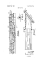
- FIG. 1 is a side elevation of the improved conveyor or feeder portion of the improved combination.
- FIG. 3 is a detail view, at enlarged scale, of one of the resilient connectors attaching the discharge section of the conveyor to the adjacent section.
- FIG. 6 is a fragmentary isometric view of the discharge end of the feeder and the cooperating anvil portion of the inlet spout of the chipper.
- FIG. 7 is a vertical transverse sectional view of one of the rubber shear spring supports for the feeder.
- FIG. 8 is an enlarged front elevation of one of the rubber shear spring supports for the feeder.
- FIGS. and the accompanying description are intended merely to illustrate the invention and not to impose limitations on its scope.
- the conveyor-feeder portion of the invention comprises an extended trough 1 that is preferably supported from a base 2 by means of a series of pairs of rocker arms 3 and rubber shear spring assemblies 4.
- the conveyor is driven by a motor driven crank and connecting rod mechanism comprising an eccentric shaft 5 that is driven from a motor 6 by means of a belt 7.
- the eccentric shaft 5 drives a connecting rod 8 connected to one end of a lever 9 pivoted on a bracket 10 depending from and attached to the conveyor trough l.
- the far end of the lever 9 is connected through a hydraulic shock absorber 11 to the trough 1.
- This particular drive mechanism as explained in US. Pat. No. 2,630,21 l, provides an efficient positive drive for vibrating the conveyor-feeder trough 1 while still allowing the trough to move slowly in response to the variations in load without imposing large static forces on the eccentric shaft 5.
- the conveyor-feeder trough 1 preferably includes a loading section 12, shown at the left end of FIG. 1, and a screening section 13 having a perforated deck 14, FIGS. 2 and 3, including a collecting trough l5 feeding into a disposal conveyor or means not shown.
- the feeder trough 1 Downstream, to the right in FIG. 1, the feeder trough 1 includes a nonmetallic section 16 equipped with a metal detector 17 which, by means not shown in the drawings, is arranged to stop the feeder should any metallic objects that would damage the blades in the chipper be detected in the material flowing toward the chipper. Such objects might include metallic tools carelessly dropped by personnel or metal imbedded in the scrap lumber being processed.
- the discharge end of the feeder-trough 1 which comprises a specially shaped trough section 20 that is attached preferably by a resilient connection, to the next preceding section of the feeder trough I.
- This discharge trough section 20 extends into an infeed spout 21 of a chipper 22, a portion of which is shown at the right end of FIG. 2.
- the chipper 22 comprises a housing 23 enclosing a heavy power driven disc rotor 24 carried on a shaft 25.
- disc rotor 24 is equipped with knives 26 arranged to slice chips off the ends of scrap lumbe'r fed into the chipper (see also FIG.
- the anvil section is that portion of the infeed spout 21 and chipper housing adjacent the path of the knives 26 that supports the material being chipped as the knives 26 slice across the ends of the pieces of material being fed into the chipper.
- the anvil section includes a substantially vertical or slightly inclined section 27 serving as a first reaction face and a generally arcuate section 28 serving as a second or locating face.
- the knives 26, while arranged to be generally radial with respect to the heavy rotor disc 24 are swept back with the radially outermost portions lagging behind the radially inner portions of the knives so that, as the knives 26 sweep past the anvil sections 27 and 28,
- the knives slice across the ends of any material being fed into the chipper rather than a straight or chisel type cut.
- the resilient mounting of the discharge section comprises bolts 30 inserted through flanges 31 of the trough sections and rubber bushings or washers 32 separating the flanges.
- the rubber bushings or washers allow sufficient flexibility so that the discharge section 20 may easily yield within the limits of the infeed spout to the force of the wood timbers being chipped and yet provide sufficient stiffness longitudinally of the feeder to vibrate at full stroke with the adjacent sections of the feeder trough 1 to feed small pieces of wood all the way into the chipper blades without leaving any dead spots.
- the conveyor-feeder trough 1 is preferably generally U-shaped in cross section having a relatively narrow flat bed such as the perforated section 14 and inclined upwardly diverging sidewalls comprising lower sections 35 and upper sections 36.
- the inclined upwardly diverging sidewalls in cooperation with the relatively narrow flat bottom section of the conveyor trough, provide a self-cleaning action that is effective in preventing any tie-ups or jams when the scrap lumber to be chipped is dumped into the input section of the conveyor trough in random orientation.
- the vibratory action combined with the shape of the trough causes the pieces of scrap lumber to orient themselves longitudinally of the trough so that they proceed along the trough in orderly fashion and flow smoothly through the discharge portion 20 and into the chipper 22.
- the feeder trough 1 is subjected to large shock forces particularly when large heavy pieces of timber are dropped into the loading section and when the large heavy pieces are engaged by'the chipper knives.
- the supports for the vibratory trough must be able to withstand such forces without overstressing the adjacent portions of the conveyor trough, the base, or the supports themselves.
- this is'accomplished by carrying the feeder trough by means of the rubber bushed rocker arm assemblies 3 which guide the trough in a particular inclined vibratory motion and by the rubber shear spring assemblies 4 that resiliently support the trough for relatively free vibratory motion in the desired direction of vibration.
- the rubber shear spring assemblies each comprises rubber blocks 45 located on either side of a plate 46 attached to and depending from the conveyor-feeder trough 1.
- the rubber blocks 45 are compressed between a pair of channel iron side plates 47 by means of a tension bolt 48 passing through holes in the rubber blocks and a clearance hole through the plate 46.
- the tension bolt 48 also passes through a sleeve 49 serving as a spacer to limit the compression of the rubber blocks 45.
- Locator rings 50 welded to the sides of the channel iron side plates 47 and the plate 46 fit within the holes in the rubber blocks 45 to hold the blocks in position.
- the channel iron side plates 47 are bolted directly to the adjacent portions of the base 2 thus forming a rugged resilient connection between the conveyor trough l and the base 2.
- This preferred apparatus provides means for unscrambling randomly supplied loads of scrap lumber, separating debris from the scrap in a screening section, inspecting it for tramp metal, and finally feeding it into a chipper throat without leaving any gaps or areas where odd pieces of lumber may lodge.
- the construction provides that the heavy shock forces on the wood being chipped are taken by a portion of the conveyor feeder backed up by the heavy chipper housing and anvil as well as providing a rugged resilient support for the conveyor trough to withstand externally applied forces without producing excessive concentrated stress in the structure.
- the apparatus is virtually free of maintenance or necessity of attendant supervision while in operation.
- a vibratory feeder and chipper for reducing scrap lumber to chips comprising:
- a substantially horizontal vibratory trough of substantial length having a discharge end that extends into the infeed spout of the chi per adjacent to the anvil of the chipper;
- rugged resilien means stressed n shear for supporting said trough for vibration in a vertical plane and stressed in compression for resisting lateral forces applied to said trough;
- a chipper feeder according to claim 1 in which the trough is divided into sections, one of which is adjacent the chipper, and a resilient connection between the section adjacent the chipper and the next preceding section of the trough.
- a chipper feeder according to claim I in which at least a portion of the trough bottom is perforated.
- a chipper feeder according to claim I in which the trough comprises at least one section of nonmetallic material to accommodate a metal detector apparatus.
- a chipper feeder according to claim 1 in which the discharge end of the trough is resiliently attached to the preceding section of the trough and projects into the associated chipper infeed spout.
- a chipper feeder according to claim 7 in which the discharge section includes a substantially vertical face adapted to absorb the lateral forces exerted by material entering the chipper.
Abstract
Description
Claims (8)
Applications Claiming Priority (1)
| Application Number | Priority Date | Filing Date | Title |
|---|---|---|---|
| US75281268A | 1968-08-15 | 1968-08-15 |
Publications (1)
| Publication Number | Publication Date |
|---|---|
| US3570773A true US3570773A (en) | 1971-03-16 |
Family
ID=25027960
Family Applications (1)
| Application Number | Title | Priority Date | Filing Date |
|---|---|---|---|
| US752812A Expired - Lifetime US3570773A (en) | 1968-08-15 | 1968-08-15 | Chipper feeder |
Country Status (5)
| Country | Link |
|---|---|
| US (1) | US3570773A (en) |
| DE (1) | DE1938773A1 (en) |
| GB (1) | GB1263096A (en) |
| NO (1) | NO129560B (en) |
| SE (1) | SE358580B (en) |
Cited By (7)
| Publication number | Priority date | Publication date | Assignee | Title |
|---|---|---|---|---|
| US4240588A (en) * | 1979-03-06 | 1980-12-23 | Fulghum Industries, Inc. | Wood chipping installation |
| US4449626A (en) * | 1981-09-24 | 1984-05-22 | Dodd Ned T | Poultry conveyor |
| US4736781A (en) * | 1986-08-26 | 1988-04-12 | Morbark Industries, Inc. | Stump disintegrator |
| US4771953A (en) * | 1987-02-17 | 1988-09-20 | Morbark Industries, Inc. | Retractable anvil chipper |
| US5323975A (en) * | 1993-03-03 | 1994-06-28 | Fulghum Industries, Inc. | Wood chipping apparatus |
| EP0985501A2 (en) * | 1998-09-09 | 2000-03-15 | Sunds Defibrator Woodhandling Oy | A method of reducing noise in a barking plant and a barking drum, chipper and conveying line |
| CN117161757A (en) * | 2023-11-02 | 2023-12-05 | 启东丰鑫泵业科技有限公司 | Electric air pump rear cover assembling system |
Families Citing this family (5)
| Publication number | Priority date | Publication date | Assignee | Title |
|---|---|---|---|---|
| DE2712961C2 (en) * | 1977-03-24 | 1988-12-22 | Klöckner-Humboldt-Deutz AG, 5000 Köln | Resonance conveyor device, especially for the bunker discharge |
| DE2727958C2 (en) * | 1977-06-22 | 1983-01-13 | Klöckner-Humboldt-Deutz AG, 5000 Köln | Resonance conveyor device, especially for the bunker discharge |
| DE3518545C1 (en) * | 1985-05-23 | 1986-12-18 | Alfred Kärcher GmbH & Co, 7057 Winnenden | Wet-cleaning device for floor coverings |
| DE3941094A1 (en) * | 1989-12-13 | 1991-06-20 | Kaercher Gmbh & Co Alfred | WET DRY SUCTION |
| DE102015212538A1 (en) * | 2015-07-03 | 2017-01-05 | Homag Holzbearbeitungssysteme Gmbh | Transport device, in particular for shavings and residual parts |
Citations (6)
| Publication number | Priority date | Publication date | Assignee | Title |
|---|---|---|---|---|
| US2582537A (en) * | 1949-10-17 | 1952-01-15 | Einar I Flateboe | Rechipper with vibrating trough |
| US2712903A (en) * | 1952-10-13 | 1955-07-12 | Murray D J Mfg Co | Wood rechipper feeder |
| US2854130A (en) * | 1954-08-12 | 1958-09-30 | Gifford Wood Co | Vibrating conveyor mounting structure |
| US2965316A (en) * | 1959-01-29 | 1960-12-20 | Reserve Mining Co | Plant operating control means |
| US3063546A (en) * | 1958-11-28 | 1962-11-13 | Gen Electric Co Ltd | Vibratory equipment |
| US3089653A (en) * | 1961-09-20 | 1963-05-14 | Dundee Cement Co | Hot clinker conveying and cooling apparatus |
-
1968
- 1968-08-15 US US752812A patent/US3570773A/en not_active Expired - Lifetime
-
1969
- 1969-06-25 GB GB31977/69A patent/GB1263096A/en not_active Expired
- 1969-07-30 DE DE19691938773 patent/DE1938773A1/en not_active Ceased
- 1969-08-06 NO NO03210/69A patent/NO129560B/no unknown
- 1969-08-12 SE SE11213/69A patent/SE358580B/xx unknown
Patent Citations (6)
| Publication number | Priority date | Publication date | Assignee | Title |
|---|---|---|---|---|
| US2582537A (en) * | 1949-10-17 | 1952-01-15 | Einar I Flateboe | Rechipper with vibrating trough |
| US2712903A (en) * | 1952-10-13 | 1955-07-12 | Murray D J Mfg Co | Wood rechipper feeder |
| US2854130A (en) * | 1954-08-12 | 1958-09-30 | Gifford Wood Co | Vibrating conveyor mounting structure |
| US3063546A (en) * | 1958-11-28 | 1962-11-13 | Gen Electric Co Ltd | Vibratory equipment |
| US2965316A (en) * | 1959-01-29 | 1960-12-20 | Reserve Mining Co | Plant operating control means |
| US3089653A (en) * | 1961-09-20 | 1963-05-14 | Dundee Cement Co | Hot clinker conveying and cooling apparatus |
Cited By (9)
| Publication number | Priority date | Publication date | Assignee | Title |
|---|---|---|---|---|
| US4240588A (en) * | 1979-03-06 | 1980-12-23 | Fulghum Industries, Inc. | Wood chipping installation |
| US4449626A (en) * | 1981-09-24 | 1984-05-22 | Dodd Ned T | Poultry conveyor |
| US4736781A (en) * | 1986-08-26 | 1988-04-12 | Morbark Industries, Inc. | Stump disintegrator |
| US4771953A (en) * | 1987-02-17 | 1988-09-20 | Morbark Industries, Inc. | Retractable anvil chipper |
| US5323975A (en) * | 1993-03-03 | 1994-06-28 | Fulghum Industries, Inc. | Wood chipping apparatus |
| EP0985501A2 (en) * | 1998-09-09 | 2000-03-15 | Sunds Defibrator Woodhandling Oy | A method of reducing noise in a barking plant and a barking drum, chipper and conveying line |
| EP0985501A3 (en) * | 1998-09-09 | 2005-01-05 | Sunds Defibrator Woodhandling Oy | A method of reducing noise in a barking plant and a barking drum, chipper and conveying line |
| CN117161757A (en) * | 2023-11-02 | 2023-12-05 | 启东丰鑫泵业科技有限公司 | Electric air pump rear cover assembling system |
| CN117161757B (en) * | 2023-11-02 | 2023-12-29 | 启东丰鑫泵业科技有限公司 | Electric air pump rear cover assembling system |
Also Published As
| Publication number | Publication date |
|---|---|
| SE358580B (en) | 1973-08-06 |
| DE1938773A1 (en) | 1970-02-19 |
| NO129560B (en) | 1974-04-29 |
| GB1263096A (en) | 1972-02-09 |
Similar Documents
| Publication | Publication Date | Title |
|---|---|---|
| US3570773A (en) | Chipper feeder | |
| KR101917568B1 (en) | Two Stage Crusher Equipped with Roll Mill and Hammer Mill | |
| US8066213B2 (en) | Replaceable tooth mount rotor system for waste fragmenting machines | |
| US4157761A (en) | Discharger mechanism | |
| US2974795A (en) | Grizzly feeders | |
| US3473742A (en) | Machine for the punching and cutting of wood | |
| US3106523A (en) | Grizzly bar feeder | |
| CN103977962B (en) | A kind of Corn sorter | |
| KR100960366B1 (en) | Sawdust mill and apparatus for manufacturing sawdust | |
| US11607710B2 (en) | Screening apparatus | |
| US2005758A (en) | Crusher | |
| US6402072B1 (en) | Method for securing a die plate of a jaw crusher, and a jaw crusher | |
| US2767928A (en) | Plural stage impact breaker with impacting rotors and adjacent deflector screen grates | |
| US2582537A (en) | Rechipper with vibrating trough | |
| US3295667A (en) | Anti-blinding mechanism for screen panels | |
| US3706376A (en) | Screen with differently tensioned surface zones | |
| KR20160031197A (en) | A quantity supply device of waste | |
| US3322354A (en) | Aggregate processing plant | |
| US3111248A (en) | Cardboard disintegrating apparatus | |
| US3105815A (en) | Vibratory feeder | |
| RU169141U1 (en) | Vibratory Jaw Crusher | |
| GB2570350A (en) | Screening bar assembly for a screen | |
| US2862668A (en) | Combination hay and grain mill | |
| US3303864A (en) | Almond cracker | |
| RU2072262C1 (en) | Grinder |
Legal Events
| Date | Code | Title | Description |
|---|---|---|---|
| AS | Assignment |
Owner name: FIRST NATIONAL BANK OF LOUISVILLE, 101 SOUTH FIFTH Free format text: SECURITY INTEREST;ASSIGNOR:CARRIER VIBRATING EQUIPMENT, INC.;REEL/FRAME:004176/0589 Effective date: 19830831 Owner name: COUNTY OF JEFFERSON, KENTUCKY, THE POLITICAL SUB Free format text: SECURITY INTEREST;ASSIGNOR:CARRIER VIBRATING EQUIPMENT, INC.;REEL/FRAME:004176/0589 Effective date: 19830831 Owner name: REXNORD INC., 3500 FIRST WISCONSIN CENTER, MILWAUK Free format text: SECURITY INTEREST;ASSIGNOR:CARRIER VIBRATING EQUIPMENT, INC.;REEL/FRAME:004176/0589 Effective date: 19830831 Owner name: CARRIER VIBRATING EQUIPMENT INC 3400 FERN VALLEY R Free format text: ASSIGNMENT OF ASSIGNORS INTEREST.;ASSIGNOR:REXNORD INC;REEL/FRAME:004167/0676 Effective date: 19830831 |