US3541663A - Syringe needle attachment device - Google Patents
Syringe needle attachment device Download PDFInfo
- Publication number
- US3541663A US3541663A US754192A US3541663DA US3541663A US 3541663 A US3541663 A US 3541663A US 754192 A US754192 A US 754192A US 3541663D A US3541663D A US 3541663DA US 3541663 A US3541663 A US 3541663A
- Authority
- US
- United States
- Prior art keywords
- barrel
- needle assembly
- secured
- head
- syringe
- Prior art date
- Legal status (The legal status is an assumption and is not a legal conclusion. Google has not performed a legal analysis and makes no representation as to the accuracy of the status listed.)
- Expired - Lifetime
Links
Images
Classifications
-
- A—HUMAN NECESSITIES
- A61—MEDICAL OR VETERINARY SCIENCE; HYGIENE
- A61M—DEVICES FOR INTRODUCING MEDIA INTO, OR ONTO, THE BODY; DEVICES FOR TRANSDUCING BODY MEDIA OR FOR TAKING MEDIA FROM THE BODY; DEVICES FOR PRODUCING OR ENDING SLEEP OR STUPOR
- A61M5/00—Devices for bringing media into the body in a subcutaneous, intra-vascular or intramuscular way; Accessories therefor, e.g. filling or cleaning devices, arm-rests
- A61M5/178—Syringes
- A61M5/31—Details
- A61M5/32—Needles; Details of needles pertaining to their connection with syringe or hub; Accessories for bringing the needle into, or holding the needle on, the body; Devices for protection of needles
- A61M5/34—Constructions for connecting the needle, e.g. to syringe nozzle or needle hub
-
- Y—GENERAL TAGGING OF NEW TECHNOLOGICAL DEVELOPMENTS; GENERAL TAGGING OF CROSS-SECTIONAL TECHNOLOGIES SPANNING OVER SEVERAL SECTIONS OF THE IPC; TECHNICAL SUBJECTS COVERED BY FORMER USPC CROSS-REFERENCE ART COLLECTIONS [XRACs] AND DIGESTS
- Y10—TECHNICAL SUBJECTS COVERED BY FORMER USPC
- Y10T—TECHNICAL SUBJECTS COVERED BY FORMER US CLASSIFICATION
- Y10T29/00—Metal working
- Y10T29/49—Method of mechanical manufacture
- Y10T29/49826—Assembling or joining
- Y10T29/49908—Joining by deforming
- Y10T29/49915—Overedge assembling of seated part
- Y10T29/49917—Overedge assembling of seated part by necking in cup or tube wall
- Y10T29/49918—At cup or tube end
-
- Y—GENERAL TAGGING OF NEW TECHNOLOGICAL DEVELOPMENTS; GENERAL TAGGING OF CROSS-SECTIONAL TECHNOLOGIES SPANNING OVER SEVERAL SECTIONS OF THE IPC; TECHNICAL SUBJECTS COVERED BY FORMER USPC CROSS-REFERENCE ART COLLECTIONS [XRACs] AND DIGESTS
- Y10—TECHNICAL SUBJECTS COVERED BY FORMER USPC
- Y10T—TECHNICAL SUBJECTS COVERED BY FORMER US CLASSIFICATION
- Y10T29/00—Metal working
- Y10T29/53—Means to assemble or disassemble
- Y10T29/53039—Means to assemble or disassemble with control means energized in response to activator stimulated by condition sensor
- Y10T29/53061—Responsive to work or work-related machine element
- Y10T29/53065—Responsive to work or work-related machine element with means to fasten by deformation
-
- Y—GENERAL TAGGING OF NEW TECHNOLOGICAL DEVELOPMENTS; GENERAL TAGGING OF CROSS-SECTIONAL TECHNOLOGIES SPANNING OVER SEVERAL SECTIONS OF THE IPC; TECHNICAL SUBJECTS COVERED BY FORMER USPC CROSS-REFERENCE ART COLLECTIONS [XRACs] AND DIGESTS
- Y10—TECHNICAL SUBJECTS COVERED BY FORMER USPC
- Y10T—TECHNICAL SUBJECTS COVERED BY FORMER US CLASSIFICATION
- Y10T29/00—Metal working
- Y10T29/53—Means to assemble or disassemble
- Y10T29/53313—Means to interrelatedly feed plural work parts from plural sources without manual intervention
- Y10T29/53322—Means to assemble container
- Y10T29/53339—Hypodermic syringe
Definitions
- a device for attaching a needle assembly to a glass barrel of a syringe The mechanism automatically places the needle assembly on the head of the syringe barrel and then deform-s the metal connector of the needle assembly around the head of the barrel.
- the machine automatically adjusts to the length of the barrel and it provides a preset downward force so that the needle assembly is properly sealed to the barrel.
- a small machine for attaching the needle assembly to the glass barrel of the syringe thereby enabling drugs to be placed in the barrel at the hospital and the needle assembly to then be secured in place. This permits the proper drug and dosage thereof to be prefilled directly at the hospital.
- the system greatly reduces the cost of the drugs and the syringe-s since the drugs can be bought in bulk quantities as well as the components of the syringe assembly.
- the machine includes means for holding the glass bar rel in an upright position and means for holding the needle assembly in alignment with the top of the glass barrel.
- the machine automatically brings the needle assembly into contact with the barrel and deforms the metal head of the needle assembly around the head of the glass barrel to form a sealed unit.
- a precise pressure is applied between the needle assembly and the glass barrel so that in every case the amount of sealing pressure does not vary.
- the machine automatically adjusts for the length of the glass barrel and the barrel is mounted on a bearing member which permits it to rotate with the needle assembly during the deforming operation.
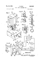
- FIG. 1 is a perspective view of the apparatus in accordance with the invention.
- FIG. 2 is a fragmentary view of the disassembled needle assembly and barrel
- FIG. 3 is a view similar to FIG. 2 but illustrating the needle assembly connected to the glass barrel;
- FIG. 4 is a plan view of the assembled syringe
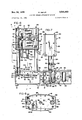
- FIG. 5 is an electrical schematic of the electrical system for the apparatus
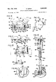
- FIG. 6 is a front elevation partially in section of the apparatus
- FIG. 7 is a section view taken along the lines 7--7 of FIG. 6;
- FIG. 8 is a sectional view taken along the lines 8-8 of FIG. 6;
- FIG. 9 is an elevation View partially in section for raising and lowering the top housing
- FIG. 10 is an elevation of the cam assembly for operating the electrical switches
- FIG. 11 is an elevation view of the saddle assembly
- FIG. 12 is a sectional view taken centrally through the support means for the needle assembly and barrel;
- FIG. 13 is a plan view, partially in section, of the mechanism for moving the deforming arm toward and away from the needle assembly.
- FIG. 14 is a plan view of the spring clip utilized to hold the glass barrel in position.
- the assembling machine 10 is shown in FIG. 1 and includes a base 11 having a plurality of feet 12 adapted to be mounted on a flat horizontal surface.
- the base or lower housing 11 has two vertically extending support posts 14 which support the upper housing 15 for vertical movement toward and away from the base 11.
- the syringe 16 is shown in FIGS. 2-4 and includes the glass barrel 17 having the annular head 18 formed at the upper end thereof with the recess 19 (FIG. 3) between the head 18 and the body 21 of the barrel.
- the needle assembly 22 includes the hollow needle 24, the plastic cover 25 for the needle 24, and the metal connector 27 which houses a resilient seal 28 having a check valve (not shown) therein.
- the connector 27 is made of metal and has the annular wall 30 having an inner diameter slightly greater than the outer diameter of the head 18 of the barrel 17 and adapted to be received over the head and have the lower edge portion 31 thereof deformed over the head 18, as shown in FIG. 3, to lock securely and seal the needle assembly 22 on the glass barrel 17.
- the piston 33 is reciprocally mounted in the glass barrel 17 and the plunger rod 35 is removably secured thereto for effecting reciprocation of the piston 33.
- the piston 33 is first placed in the glass barrel 17 and then the drug is placed into the barrel from the opening 36 in the head thereof, and then the needle assembly 22 is secured thereto by the machine 10.
- the plunger rod 35 is usually not secured in place until shortly before the drug is to be administered.
- the mechanism of the machine 10 which raises and lowers the upper housing 15 is shown in FIGS. 6-11 and includes the drive motor and a gear unit 41 rigidly secured in the base 11 by the bracket 43 which includes the plate 41 fastened to the top wall 45 of the base 11 and the downwardly extending flange portion 45 to which the gear unit 43 is secured.
- the output shaft of the gear unit 43 has a circular drive disk 48 rigidly secured thereto adapted to raise and lower the saddle assembly 50, as will be described.
- the saddle assembly 50 includes (FIGS. 9 and 11) the cross member 51 having its ends secured to the vertical actuator rods 52 by the nuts 53 which engage the threaded connections 54 on the lower ends 55 of the actuator rods 52 and clamp the ends of the cross member 51 against the shoulders 55 formed on the rods.
- These rods extend vertically through the support posts 14 and have their upper ends 56 rigidly secured to the cross plate 57 in the upper housing 15 by the nuts 58 which engage the threaded ends 59 of the actuator rods 52, as shown in FIG. 6.
- the lower end of the posts 14 are rigidly secured to the top wall 46 of the base 11 by the nuts 60 which engage the threads 61 on the reduced diameter end portions 62 of these rods, whereas the upper ends of the posts extend through openings 63 in the lower cross member 64 of the upper housing 15 and are unsupported at this point.
- the cross member 51 of the saddle assembly 50 has secured thereto an actuator plate 65 which extends parallel thereto and its ends are secured in position by the elongated screws 66 which extend through the openings 67 in the ends of the actuator plate 65, through the spacer blocks 68, and through the openings 69 in the cross member 51.
- a coil spring 71 surrounds each of the screws 66 between the top surface 72 of the cross member 51 and the nut 73 on the end of the screws 66 so that the actuator plate 65 can move with respect to the cross member 51 against the bias of the springs 71. In effect, when the preset pressure is applied to the actuator plate 65 it will move away from the cross member 51.
- a suitable electrical switch 75 is secured by the screws 76 to the side 77 of the actuator plate 65 with its actuating arm 78 resting against the bottom surface 79 of the cross member 51 so that, when the distance between the actuator plate 65 and cross member 51 changes, the switch 75 is actuated.
- the drive mechanism in the base 11 includes a roller 80 rotatably mounted near the periphery of the circular drive disk 48 and received between the bottom surface 79 of cross member 51 and the top surface 82 of the actuator plate 65 so that rotation of the disk 48 causes the roller 80 to engage one of these surfaces to move the saddle assembly 50 between a raised and a lowered position, as shown by the broken and solid lines of FIG. 9. Movement of the saddle assembly 50 causes corresponding movement of the actuator rods 52 thus raising and lowering the upper housing 15.
- the upper housing -15 itself includes the lower 64, intermediate 57, and top plates 83 on which most of the components are secured and which are secured together by the side walls 84 of the upper housing 15.
- the front and rear plates 85 and 86 can be easily removed by the access of the interior of the upper housing.
- the top and lower plates 83 and 84 are secured to the intermediate plate 57 by four vertically extending posts 88 which are secured to the corners of the intermediate plate 57 and are bolted to the top and lower plates 83 and 84 by nuts '89.
- the top and lower plates 83 and 64 are similarly moved.
- the drive head 90 for the needle assembly is mounted on the lower plate 64 and includes a drive motor 91 having its output shaft 92 extending through the thrust bearing 93 in the opening 94 in the center of the lower plate 64 and having mounted thereon a chuck 95, as shown in FIGS. 6 and 12.
- the chuck 95 is secured on the end of the drive shaft 92 by the set screw 96 which engages the fiat 97 on the drive shaft 92.
- An elongated recess 98 extends axially through the lower end of the chuck 95 a substantial distance corresponding to the length of the plastic covering 28 on the needle assembly 22.
- the plastic covering snugly fits this opening and the spring biased ball detent 99 is urged against the plastic covering 22 so that the needle assembly is held snugly in the recess 98.
- the lower end 100 of the chuck 95 engages the metal connector 30 at the radial shoulder 30a thereof so that the downward force can be applied to the connector 30.
- the support for the glass barrel 17 includes a rubber disk 102 adapted to have seated thereon the outwardly flared lower end 17a of the glass barrel 17.
- This rubber disk is supported for rotation of the ball bearings 103 by the upstanding shaft 104 which is supported on the top wall 46 of the base 11.
- the bearing 103 is mounted around the shaft so that the downward pressure on the barrel 17 is absorbed by this bearing which permits the support disk 102 to rotate with the barrel.
- the barrel 17 is held in position by the U-shaped spring clip 105, shown in FIG. 14, including an upstanding bracket 106 secured on the top wall 46 of the base -11 and which has the clip secured thereto by the conventional connector 107.
- the V-shaped groove 108 is provided in the bracket 106 to seat the side surfaces of the glass barrel 17 which is held thereagainst by the spring clip 105.
- the movement of the crimping arm 110 (FIG. 6) toward and away from the metal connector 25 is eifected by the drive motor 111 mounted on the intermediate plate 57.
- Its drive shaft 112 extends through the plate 57 and has the eccentric cam 114 (FIG. 13) on the lower end thereof adapted to pivot the arm 115 which has the cam follower 116 thereon to engage the outer periphery 116a of the cam 114.
- the arm pivots about the downwardly extending shaft 117 whose lower end 118 is connected to and supports the crimping arm 110.
- the coil spring 119 urges the other end of the arm 115 toward the cam 114 so that the cam follower 116 is maintained in contact with the cam 114 at all times.
- An electrical switch 121 is mounted on the plate 57 to be actuated by the bracket 122 mounted on the arm 114 so that this switch senses the position of the actuator arm 114 and thus the crimping arm 110.
- the crimping arm 110 is rigidly secured to the lower end of the elongated shaft 117 which is mounted for rotation in the tubular member 124 secured to the lower plate 64 by the screws 124a (FIG. 6).
- the upper end of the pivot shaft 117 extends through the bearing 117a mounted in the intermediate plate 57 so that the shaft rotates without any binding forces.
- Downward movement of the shaft is limited by the collar 125 adjustably secured thereto by the set screw 126 and the coil spring 127 interposed between the collar 125 and the upper end 128 of the tubular member 124 to resist downward movement of the shaft.
- a slight downward movement against the bias of this spring 127 is possible and is required to seat properly the deforming wheel 120 mounted on the outer end of the crimping arm 110 against the metal connector 24 during the deforming operation.
- the electrical system for the machine 10 includes a number of electrical switches 75 and 121 which have already been described.
- an on-oif switch (FIG. 7) is provided in the front plate 136 of the base 11 together with a cycle start button 137 and a light 138 indicates the position of the on-oif switch 135.
- the drive disk 48 mounted in the base 11 and driven by the motor 50 has an elongated cam lobe 140 mounted thereon adapted to actuate two electrical switches 141 and 1 42 (FIG. 10') as the drive disk 48 is rotated.
- the first of these switches 141 is utilized to hold the circuitry in its energized position once the cycle start button 137 is momentarily depressed and the other of the switches 142 is utilized to start the crimping operation once the upper housing 15 has positioned the needle assembly 22 on the glass barrel 17.
- the attachment device operates by merely closing the manual switch 135 located on the front plate 136 of the base 11.
- a glass barrel 17 is then placed in the spring clip 105 against the bracket 106 with the lower flared end 17a being supported on the rotatable disk 102'.
- the needle assembly 22 is placed into the chuck 95 by merely inserting it upwardly into the chuck 95 until the lower end of the chuck 95 rests against the shoulder 30a on the metal connector 30 on the end thereof.
- the piston 33 will already have been placed in the glass barrel 17 together with a prescribed quantity of drug or other medication.
- the carm lobe 1'40 mounted on the drive disk 48 will have rotated sufficiently to close switch 142 completing the circuit through the conductors 175 and 176 to the spin and cam motors 91 and 111 which immediately begin to rotate.
- the switch 141 has opened by the cam lobe 140 revolving so that the circuit to the relay coil 155 is deenergized causing the switches 157 and 158 to be moved upwardly to the contacts 177 and 17-8.
- the motor 91 rotates the chuck '95 and thus the needle assembly 22 and the barrel 17 which rotate with the support disk 102.
- the motor 111 moves the arm 115 and deforming tool 110 against the connector edge 31 to deform it around the head 18 of the barrel 17 to create a fluid tight connection.
- the cam switch 121 is again closed so that power flows through the conductor 173, the switch 158, and the conductor 170 to the drive motor 40 causing it to rotate in an opposite direction to raise the housing 15 which moves to its raised or retracted position.
- the spin and cam start switch 142 is released causing the cam and spin motors 91 and 111 to stop with the arm 110 in its retracted position.
- the switch 179 in conductor is opened to terminate flow of current to the motor 40 and thus deenengize the same.
- the circuitry and mechanism is then in the same state as it was when the cycle was first started, and the cycle can be repeated by merely pushing the button 137 in conduct or to initiate the same. However, before doing so the completed syringe 16 is removed from the bracket and a new needle assembly 22 and barrel 17 are placed in the machine 10.
- the invention has thus provided a machine for attaching the needle assembly to the glass barrel of a syringe thereby enabling the drug to be placed in the barrel at the hospital and the needle assembly to be secured or formed in place.
- the invention includes means for holding the glass barrel and needle assemblies in alignment and for automatically moving a deforming arm into position to deform the needle assembly over the head of the barrel and thus secure the same together with a preset pressure therebetween which eliminates the possibility of leakage between the needle assembly and the barrel.
- a syringe needle attachment device adapted to secure the metal connector on one end of a needle assembly to the head of a glass barrel by deforming the outer periphery of the metal connection over the head of the glass barrel, said device comprising a first and second housings, means on one of said housings adapted to receive and support the barrel of the syringe assembly, chuck means on the other said housings adapted to receive and hold the needle assembly with the metal connector thereof in alignment with the head on the barrel, motor means for moving one of said housings toward the other of said housing until the connector is seated on the head of the barrel, means for rotating said chuck means to rotate the needle assembly and the barrel and for maintaining a preset downward pressure of said connector against the head of the barrel during such rotation, and automatic means for automatically deforming the connector over the head to interconnect securely the needle assembly and the barrel.
- said means for mounting said first housing on said second housing includes at least one post rigidly secured to said first housing, an actuator rod extending through said post and being securely connected to said first housing, and motor means in said second housing for moving said actuator rod between spaced first and second positions.
- a device as defined in claim 2 wherein means are provided for terminating operation of said motor means when a preset resistance is applied to the movement of said housings toward each other.
- a device as defined in claim 3 wherein a pair of said posts and actuator rods are provided on opposite sides of said second housing, a saddle assem'bly interconnecting the ends of said actuator rods, said saddle assembly including a cross member which is rigidly secured to one end of said actuator rods, an actuator plate resiliently mounted on said cross :member, an electrical switch mounted on said saddle assembly to sense when there is relative movement between said actuator plate and said cross member, said motor means including a rotating disk having a roller adapted to engage said actuator member to move said saddle assembly and said actuator rods.
- a device as provided in claim 1 wherein a spring bracket is provided to support the glass barrel on said second housing, a rotatable disk on one of said housings to support the lowermost end of the barrel for rotation, and said spring adapted to hold the barrel on said disk.
Description
R. SZPUR SYRINGE NEEDLE ATTACHMENT DEVICE Nov. 24, 1970 3 Sheets-Sheetl v Filed Aug. 21, 1968 FIG-4 FIG-2 INVENTOR ROMAN SZPUR Nov. 24, 1970 R. SZP-UR V SYRINGE NEEDLE ATTACHMENT DEVICE 5 SheecsSheet 5 Filed Aug. 21, 1968 FIG-9 FIG-12 FIG-H United States Patent O 3,541,663 SYRINGE NEEDLE ATIACI-llVIENT DEVICE Roman Szpur, 2685 Culver Ave., Kettering, Ohio 45429 Filed Aug. 21, 1968, Ser. No. 754,192 Int. Cl. B2311 19/04 US. Cl. 29-208 7 Claims ABSTRACT OF THE DISCLOSURE A device for attaching a needle assembly to a glass barrel of a syringe. The mechanism automatically places the needle assembly on the head of the syringe barrel and then deform-s the metal connector of the needle assembly around the head of the barrel. The machine automatically adjusts to the length of the barrel and it provides a preset downward force so that the needle assembly is properly sealed to the barrel.
BACKGROUND OF THE INVENTION The use of syringes throughout hospitals and the like to administer drugs to patients is extensive, thus creating problems of sterilizing the syringes as well as the handling and filling thereof. A new approach has occurred in recent years, that is, the use of prefilled throw-away or disposable syringe assemblies which are used only once and then disposed of. In this manner, they can be sterilized at the factory and placed in a sealed container until ready for use.
However, this presents a problem since only the more frequently used drugs can be provided in this manner, and then the dosage provided in the syringe is often more or less than the amount desired. Since the less frequently used drugs are not provided in syringes of this type, the hospital must still maintain the reusable syringes and all the related sterilization equipment.
SUMMARY OF THE INVENTION A small machine for attaching the needle assembly to the glass barrel of the syringe thereby enabling drugs to be placed in the barrel at the hospital and the needle assembly to then be secured in place. This permits the proper drug and dosage thereof to be prefilled directly at the hospital. In addition, the system greatly reduces the cost of the drugs and the syringe-s since the drugs can be bought in bulk quantities as well as the components of the syringe assembly.
The machine includes means for holding the glass bar rel in an upright position and means for holding the needle assembly in alignment with the top of the glass barrel. The machine automatically brings the needle assembly into contact with the barrel and deforms the metal head of the needle assembly around the head of the glass barrel to form a sealed unit. A precise pressure is applied between the needle assembly and the glass barrel so that in every case the amount of sealing pressure does not vary. In one embodiment, the machine automatically adjusts for the length of the glass barrel and the barrel is mounted on a bearing member which permits it to rotate with the needle assembly during the deforming operation.
BRIEF DESCRIPTION OF THE DRAWINGS FIG. 1 is a perspective view of the apparatus in accordance with the invention;
FIG. 2 is a fragmentary view of the disassembled needle assembly and barrel;
FIG. 3 is a view similar to FIG. 2 but illustrating the needle assembly connected to the glass barrel;
FIG. 4 is a plan view of the assembled syringe;
FIG. 5 is an electrical schematic of the electrical system for the apparatus;
FIG. 6 is a front elevation partially in section of the apparatus;
FIG. 7 is a section view taken along the lines 7--7 of FIG. 6;
FIG. 8 is a sectional view taken along the lines 8-8 of FIG. 6;
FIG. 9 is an elevation View partially in section for raising and lowering the top housing;
FIG. 10 is an elevation of the cam assembly for operating the electrical switches;
FIG. 11 is an elevation view of the saddle assembly;
FIG. 12 is a sectional view taken centrally through the support means for the needle assembly and barrel;
FIG. 13 is a plan view, partially in section, of the mechanism for moving the deforming arm toward and away from the needle assembly; and
FIG. 14 is a plan view of the spring clip utilized to hold the glass barrel in position.
DETAILED DESCRIPTION OF THE PREFERRED EMBODIMENT The assembling machine 10 is shown in FIG. 1 and includes a base 11 having a plurality of feet 12 adapted to be mounted on a flat horizontal surface. The base or lower housing 11 has two vertically extending support posts 14 which support the upper housing 15 for vertical movement toward and away from the base 11.
The syringe 16 is shown in FIGS. 2-4 and includes the glass barrel 17 having the annular head 18 formed at the upper end thereof with the recess 19 (FIG. 3) between the head 18 and the body 21 of the barrel. The needle assembly 22 includes the hollow needle 24, the plastic cover 25 for the needle 24, and the metal connector 27 which houses a resilient seal 28 having a check valve (not shown) therein. The connector 27 is made of metal and has the annular wall 30 having an inner diameter slightly greater than the outer diameter of the head 18 of the barrel 17 and adapted to be received over the head and have the lower edge portion 31 thereof deformed over the head 18, as shown in FIG. 3, to lock securely and seal the needle assembly 22 on the glass barrel 17.
The piston 33 is reciprocally mounted in the glass barrel 17 and the plunger rod 35 is removably secured thereto for effecting reciprocation of the piston 33. In practice, the piston 33 is first placed in the glass barrel 17 and then the drug is placed into the barrel from the opening 36 in the head thereof, and then the needle assembly 22 is secured thereto by the machine 10. The plunger rod 35 is usually not secured in place until shortly before the drug is to be administered.
The mechanism of the machine 10 which raises and lowers the upper housing 15 is shown in FIGS. 6-11 and includes the drive motor and a gear unit 41 rigidly secured in the base 11 by the bracket 43 which includes the plate 41 fastened to the top wall 45 of the base 11 and the downwardly extending flange portion 45 to which the gear unit 43 is secured. The output shaft of the gear unit 43 has a circular drive disk 48 rigidly secured thereto adapted to raise and lower the saddle assembly 50, as will be described.
The saddle assembly 50 includes (FIGS. 9 and 11) the cross member 51 having its ends secured to the vertical actuator rods 52 by the nuts 53 which engage the threaded connections 54 on the lower ends 55 of the actuator rods 52 and clamp the ends of the cross member 51 against the shoulders 55 formed on the rods. These rods extend vertically through the support posts 14 and have their upper ends 56 rigidly secured to the cross plate 57 in the upper housing 15 by the nuts 58 which engage the threaded ends 59 of the actuator rods 52, as shown in FIG. 6. The lower end of the posts 14 are rigidly secured to the top wall 46 of the base 11 by the nuts 60 which engage the threads 61 on the reduced diameter end portions 62 of these rods, whereas the upper ends of the posts extend through openings 63 in the lower cross member 64 of the upper housing 15 and are unsupported at this point.
The cross member 51 of the saddle assembly 50 has secured thereto an actuator plate 65 which extends parallel thereto and its ends are secured in position by the elongated screws 66 which extend through the openings 67 in the ends of the actuator plate 65, through the spacer blocks 68, and through the openings 69 in the cross member 51. A coil spring 71 surrounds each of the screws 66 between the top surface 72 of the cross member 51 and the nut 73 on the end of the screws 66 so that the actuator plate 65 can move with respect to the cross member 51 against the bias of the springs 71. In effect, when the preset pressure is applied to the actuator plate 65 it will move away from the cross member 51. A suitable electrical switch 75 is secured by the screws 76 to the side 77 of the actuator plate 65 with its actuating arm 78 resting against the bottom surface 79 of the cross member 51 so that, when the distance between the actuator plate 65 and cross member 51 changes, the switch 75 is actuated.
The drive mechanism in the base 11 includes a roller 80 rotatably mounted near the periphery of the circular drive disk 48 and received between the bottom surface 79 of cross member 51 and the top surface 82 of the actuator plate 65 so that rotation of the disk 48 causes the roller 80 to engage one of these surfaces to move the saddle assembly 50 between a raised and a lowered position, as shown by the broken and solid lines of FIG. 9. Movement of the saddle assembly 50 causes corresponding movement of the actuator rods 52 thus raising and lowering the upper housing 15.
The upper housing -15 itself includes the lower 64, intermediate 57, and top plates 83 on which most of the components are secured and which are secured together by the side walls 84 of the upper housing 15. The front and rear plates 85 and 86 can be easily removed by the access of the interior of the upper housing. In addition, the top and lower plates 83 and 84 are secured to the intermediate plate 57 by four vertically extending posts 88 which are secured to the corners of the intermediate plate 57 and are bolted to the top and lower plates 83 and 84 by nuts '89. Thus by moving the intermediate plate 57 on the actuator rods 56, the top and lower plates 83 and 64 are similarly moved.
The drive head 90 for the needle assembly is mounted on the lower plate 64 and includes a drive motor 91 having its output shaft 92 extending through the thrust bearing 93 in the opening 94 in the center of the lower plate 64 and having mounted thereon a chuck 95, as shown in FIGS. 6 and 12. The chuck 95 is secured on the end of the drive shaft 92 by the set screw 96 which engages the fiat 97 on the drive shaft 92. An elongated recess 98 extends axially through the lower end of the chuck 95 a substantial distance corresponding to the length of the plastic covering 28 on the needle assembly 22. The plastic covering snugly fits this opening and the spring biased ball detent 99 is urged against the plastic covering 22 so that the needle assembly is held snugly in the recess 98. The lower end 100 of the chuck 95 engages the metal connector 30 at the radial shoulder 30a thereof so that the downward force can be applied to the connector 30.
As shown in FIGS 12 and 14, the support for the glass barrel 17 includes a rubber disk 102 adapted to have seated thereon the outwardly flared lower end 17a of the glass barrel 17. This rubber disk is supported for rotation of the ball bearings 103 by the upstanding shaft 104 which is supported on the top wall 46 of the base 11. The bearing 103 is mounted around the shaft so that the downward pressure on the barrel 17 is absorbed by this bearing which permits the support disk 102 to rotate with the barrel. The barrel 17 is held in position by the U-shaped spring clip 105, shown in FIG. 14, including an upstanding bracket 106 secured on the top wall 46 of the base -11 and which has the clip secured thereto by the conventional connector 107. The V-shaped groove 108 is provided in the bracket 106 to seat the side surfaces of the glass barrel 17 which is held thereagainst by the spring clip 105.
The movement of the crimping arm 110 (FIG. 6) toward and away from the metal connector 25 is eifected by the drive motor 111 mounted on the intermediate plate 57. Its drive shaft 112 extends through the plate 57 and has the eccentric cam 114 (FIG. 13) on the lower end thereof adapted to pivot the arm 115 which has the cam follower 116 thereon to engage the outer periphery 116a of the cam 114. The arm pivots about the downwardly extending shaft 117 whose lower end 118 is connected to and supports the crimping arm 110. The coil spring 119 urges the other end of the arm 115 toward the cam 114 so that the cam follower 116 is maintained in contact with the cam 114 at all times. An electrical switch 121 is mounted on the plate 57 to be actuated by the bracket 122 mounted on the arm 114 so that this switch senses the position of the actuator arm 114 and thus the crimping arm 110.
The crimping arm 110 is rigidly secured to the lower end of the elongated shaft 117 which is mounted for rotation in the tubular member 124 secured to the lower plate 64 by the screws 124a (FIG. 6). The upper end of the pivot shaft 117 extends through the bearing 117a mounted in the intermediate plate 57 so that the shaft rotates without any binding forces. Downward movement of the shaft is limited by the collar 125 adjustably secured thereto by the set screw 126 and the coil spring 127 interposed between the collar 125 and the upper end 128 of the tubular member 124 to resist downward movement of the shaft. However, a slight downward movement against the bias of this spring 127 is possible and is required to seat properly the deforming wheel 120 mounted on the outer end of the crimping arm 110 against the metal connector 24 during the deforming operation.
The electrical system for the machine 10 includes a number of electrical switches 75 and 121 which have already been described. In addition, an on-oif switch (FIG. 7) is provided in the front plate 136 of the base 11 together with a cycle start button 137 and a light 138 indicates the position of the on-oif switch 135. In addition, the drive disk 48 mounted in the base 11 and driven by the motor 50 has an elongated cam lobe 140 mounted thereon adapted to actuate two electrical switches 141 and 1 42 (FIG. 10') as the drive disk 48 is rotated. The first of these switches 141 is utilized to hold the circuitry in its energized position once the cycle start button 137 is momentarily depressed and the other of the switches 142 is utilized to start the crimping operation once the upper housing 15 has positioned the needle assembly 22 on the glass barrel 17.
The operation of the attachment device is best described in connection with the electrical schematic shown in FIG. 5. Accordingly, assuming that the electric current is connected thereto through the male plug 150 and that the current is supplied to the conductors 151 and 152, the device 150 operates by merely closing the manual switch 135 located on the front plate 136 of the base 11. A glass barrel 17 is then placed in the spring clip 105 against the bracket 106 with the lower flared end 17a being supported on the rotatable disk 102'. At the same time the needle assembly 22 is placed into the chuck 95 by merely inserting it upwardly into the chuck 95 until the lower end of the chuck 95 rests against the shoulder 30a on the metal connector 30 on the end thereof. The piston 33 will already have been placed in the glass barrel 17 together with a prescribed quantity of drug or other medication.
Now the operation of securing the needle assembly 22 to the glass barrel 17 is ready to be performed and is started by momentarily closing the push button switch 137 in the connector 154 which completes a circuit through the relay coil 155 in conductor 156 causing it to be energized to move the electrical switches 157 and 158 to the position against the contacts 160 and 161. At the same time, the power on lamp 138 and cycle operating lamp 164 in the conductors 165and 166 are energized to display the condition of the apparatus 10 to the operator.
As the switch 157 moves against the contact 160 the reversible motor 40 is energized by flow of current through the conductors 154, 168, and 169. This initial movement of switch 157 allowing the current flow is maintained (through normally closed switch 140 in line 173) to the drive motor 40 which rotates the disk 48 and thus moves the saddle assembly 50 downwardly bringing with it the actuator rods 56 and the upper housing 15. Once the needle assembly 24 mounted in the chuck 95 comes into contact with the head 18 of the glass barrel 17 the resistance to downward movement of the upper housing is incurred causing the roller 80 to force the actuator plate 77 downwardly against the bias of the springs 71. Movement of this plate 77 with respect to the cross member 51 only occurs when a preset force is exerted between the barrel 17 and needle assembly 22 thus causing the switch 75 in conductor 168 to open and terminate current through the drive motor 40 which immediately stops.
The carm lobe 1'40 mounted on the drive disk 48 will have rotated sufficiently to close switch 142 completing the circuit through the conductors 175 and 176 to the spin and cam motors 91 and 111 which immediately begin to rotate. At this time the switch 141 has opened by the cam lobe 140 revolving so that the circuit to the relay coil 155 is deenergized causing the switches 157 and 158 to be moved upwardly to the contacts 177 and 17-8. The motor 91 rotates the chuck '95 and thus the needle assembly 22 and the barrel 17 which rotate with the support disk 102. At the same time, the motor 111 moves the arm 115 and deforming tool 110 against the connector edge 31 to deform it around the head 18 of the barrel 17 to create a fluid tight connection.
After the single revolution of the eccentric cam 114, the cam switch 121 is again closed so that power flows through the conductor 173, the switch 158, and the conductor 170 to the drive motor 40 causing it to rotate in an opposite direction to raise the housing 15 which moves to its raised or retracted position. Once the motor 40 begins to operate, the spin and cam start switch 142 is released causing the cam and spin motors 91 and 111 to stop with the arm 110 in its retracted position. When the upper housing 15 reaches its upward position, the switch 179 in conductor is opened to terminate flow of current to the motor 40 and thus deenengize the same.
The circuitry and mechanism is then in the same state as it was when the cycle was first started, and the cycle can be repeated by merely pushing the button 137 in conduct or to initiate the same. However, before doing so the completed syringe 16 is removed from the bracket and a new needle assembly 22 and barrel 17 are placed in the machine 10.
The invention has thus provided a machine for attaching the needle assembly to the glass barrel of a syringe thereby enabling the drug to be placed in the barrel at the hospital and the needle assembly to be secured or formed in place. The invention includes means for holding the glass barrel and needle assemblies in alignment and for automatically moving a deforming arm into position to deform the needle assembly over the head of the barrel and thus secure the same together with a preset pressure therebetween which eliminates the possibility of leakage between the needle assembly and the barrel.
While the form of apparatus herein described constitutes a preferred embodiment of the invention, it is to be understood that the invention is not limited to this precise form of apparatus, and that changes may be made therein without departing from the scope of the invention which is defined in the appended claims.
What is claimed is:
1. A syringe needle attachment device adapted to secure the metal connector on one end of a needle assembly to the head of a glass barrel by deforming the outer periphery of the metal connection over the head of the glass barrel, said device comprising a first and second housings, means on one of said housings adapted to receive and support the barrel of the syringe assembly, chuck means on the other said housings adapted to receive and hold the needle assembly with the metal connector thereof in alignment with the head on the barrel, motor means for moving one of said housings toward the other of said housing until the connector is seated on the head of the barrel, means for rotating said chuck means to rotate the needle assembly and the barrel and for maintaining a preset downward pressure of said connector against the head of the barrel during such rotation, and automatic means for automatically deforming the connector over the head to interconnect securely the needle assembly and the barrel.
2. A device as defined in claim 1 wherein said means for mounting said first housing on said second housing includes at least one post rigidly secured to said first housing, an actuator rod extending through said post and being securely connected to said first housing, and motor means in said second housing for moving said actuator rod between spaced first and second positions.
3. A device as defined in claim 2 wherein means are provided for terminating operation of said motor means when a preset resistance is applied to the movement of said housings toward each other.
4. A device as defined in claim 3 wherein a pair of said posts and actuator rods are provided on opposite sides of said second housing, a saddle assem'bly interconnecting the ends of said actuator rods, said saddle assembly including a cross member which is rigidly secured to one end of said actuator rods, an actuator plate resiliently mounted on said cross :member, an electrical switch mounted on said saddle assembly to sense when there is relative movement between said actuator plate and said cross member, said motor means including a rotating disk having a roller adapted to engage said actuator member to move said saddle assembly and said actuator rods.
5. A device as provided in claim 1 wherein a spring bracket is provided to support the glass barrel on said second housing, a rotatable disk on one of said housings to support the lowermost end of the barrel for rotation, and said spring adapted to hold the barrel on said disk.
6. A syringe needle device as defined in claim 1 wherein said first housing is an upper housing and said second upper housing is a lower spaced below said upper housing, said upper housing being adapted to be lowered toward said lower housing to move the needle assembly into contact with the barrel, and reversable motor means for raising and lowering said upper housing.
7. A syringe needle attachment device as defined in claim 6 wherein said upper housing includes three parallel horizontal plates, crimping means mounted on the intermediate of said plates and including an arm adapted on the needle assembly, and chuck means mounted on the lowermost of said plates adapted to receive and support said needle assembly with the connector aligned with said tool.
References Cited to pivot a deforming tool to contact with the connector 10 THOMAS H. EAGER, Primary Examiner UNITED STATES PATENT OFFICE CERTIFICATE OF CORRECTION Patent No, Dated November 24,
Roman Szpur Inventor(s) It is certified that error appears in the above-identified patent and that said Letters Patent are hereby corrected as shown below:
Column 3, line 63, after "by insert the Column 6 line 34, "after "other" insert of Column 7, line 1, after "lower" insert housing Signed and sealed this 11th day of May 1971.
(SEAL) Attest:
EDWARD M.FLETCHER,JR. WILLIAM E. SCHUYLER, J Attesting Officer Commissioner of Patent ..i.i.... -AIL
Applications Claiming Priority (1)
| Application Number | Priority Date | Filing Date | Title |
|---|---|---|---|
| US75419268A | 1968-08-21 | 1968-08-21 |
Publications (1)
| Publication Number | Publication Date |
|---|---|
| US3541663A true US3541663A (en) | 1970-11-24 |
Family
ID=25033798
Family Applications (1)
| Application Number | Title | Priority Date | Filing Date |
|---|---|---|---|
| US754192A Expired - Lifetime US3541663A (en) | 1968-08-21 | 1968-08-21 | Syringe needle attachment device |
Country Status (2)
| Country | Link |
|---|---|
| US (1) | US3541663A (en) |
| FR (1) | FR2016079A1 (en) |
Cited By (7)
| Publication number | Priority date | Publication date | Assignee | Title |
|---|---|---|---|---|
| US3683483A (en) * | 1971-01-18 | 1972-08-15 | Upjohn Co | Apparatus for automatically attaching a sleeve to a cylindrical member |
| WO2012129174A1 (en) * | 2011-03-18 | 2012-09-27 | Abbott Laboratories | Systems. devices and methods for assembling automatic injection devices and sub-asseblies thereof |
| CN103071991A (en) * | 2012-12-17 | 2013-05-01 | 华中科技大学 | Needle head installation device for infusion tube |
| CN103522049A (en) * | 2013-09-29 | 2014-01-22 | 无锡众望四维科技有限公司 | Needle installation device of syringe needle installation machine |
| US8668670B2 (en) | 2004-06-23 | 2014-03-11 | Abbvie Biotechnology Ltd | Automatic injection devices |
| US8679061B2 (en) | 2006-06-30 | 2014-03-25 | Abbvie Biotechnology Ltd | Automatic injection device |
| US9878102B2 (en) | 2011-01-24 | 2018-01-30 | Abbvie Biotechnology Ltd. | Automatic injection devices having overmolded gripping surfaces |
Citations (1)
| Publication number | Priority date | Publication date | Assignee | Title |
|---|---|---|---|---|
| US3451116A (en) * | 1966-09-27 | 1969-06-24 | Walter A Shields | Machine for crimping a ferrule to a hypodermic needle |
-
1968
- 1968-08-21 US US754192A patent/US3541663A/en not_active Expired - Lifetime
-
1969
- 1969-08-21 FR FR6928701A patent/FR2016079A1/fr not_active Withdrawn
Patent Citations (1)
| Publication number | Priority date | Publication date | Assignee | Title |
|---|---|---|---|---|
| US3451116A (en) * | 1966-09-27 | 1969-06-24 | Walter A Shields | Machine for crimping a ferrule to a hypodermic needle |
Cited By (17)
| Publication number | Priority date | Publication date | Assignee | Title |
|---|---|---|---|---|
| US3683483A (en) * | 1971-01-18 | 1972-08-15 | Upjohn Co | Apparatus for automatically attaching a sleeve to a cylindrical member |
| US9017287B2 (en) | 2004-06-23 | 2015-04-28 | Abbvie Biotechnology Ltd | Automatic injection devices |
| US9764090B2 (en) | 2004-06-23 | 2017-09-19 | Abbvie Biotechnology Ltd | Relating to automatic injection devices |
| US8668670B2 (en) | 2004-06-23 | 2014-03-11 | Abbvie Biotechnology Ltd | Automatic injection devices |
| US8679061B2 (en) | 2006-06-30 | 2014-03-25 | Abbvie Biotechnology Ltd | Automatic injection device |
| US9486584B2 (en) | 2006-06-30 | 2016-11-08 | Abbvie Biotechnology Ltd. | Automatic injection device |
| US11565048B2 (en) | 2011-01-24 | 2023-01-31 | Abbvie Biotechnology Ltd. | Automatic injection devices having overmolded gripping surfaces |
| US9878102B2 (en) | 2011-01-24 | 2018-01-30 | Abbvie Biotechnology Ltd. | Automatic injection devices having overmolded gripping surfaces |
| CN103608053A (en) * | 2011-03-18 | 2014-02-26 | 艾伯维公司 | Systems, devices and methods for assembling automatic injection devices and sub-assemblies thereof |
| AU2012231178B2 (en) * | 2011-03-18 | 2015-11-05 | Abbvie Inc. | Systems, devices and methods for assembling automatic injection devices and sub-assemblies thereof |
| CN103608053B (en) * | 2011-03-18 | 2016-06-22 | 艾伯维公司 | For assembling the system of automated injection device and sub-component thereof, apparatus and method |
| JP2014511711A (en) * | 2011-03-18 | 2014-05-19 | アッヴィ・インコーポレイテッド | System, device, and method for assembling an automatic injection device and its subassemblies |
| WO2012129174A1 (en) * | 2011-03-18 | 2012-09-27 | Abbott Laboratories | Systems. devices and methods for assembling automatic injection devices and sub-asseblies thereof |
| CN103071991B (en) * | 2012-12-17 | 2015-06-03 | 华中科技大学 | Needle head installation device for infusion tube |
| CN103071991A (en) * | 2012-12-17 | 2013-05-01 | 华中科技大学 | Needle head installation device for infusion tube |
| CN103522049B (en) * | 2013-09-29 | 2016-02-17 | 无锡众望四维科技有限公司 | The pin-packaging device of syringe pointer assembling machine |
| CN103522049A (en) * | 2013-09-29 | 2014-01-22 | 无锡众望四维科技有限公司 | Needle installation device of syringe needle installation machine |
Also Published As
| Publication number | Publication date |
|---|---|
| FR2016079A1 (en) | 1970-04-30 |
Similar Documents
| Publication | Publication Date | Title |
|---|---|---|
| US3807467A (en) | Medicament filling unit | |
| US3541663A (en) | Syringe needle attachment device | |
| CN204568141U (en) | Automatically fall glass capping device and drinks machine | |
| US3662517A (en) | Syringe filling apparatus | |
| US20120325365A1 (en) | Automated syringe filler and loading apparatus | |
| CN111959923A (en) | Help old medicine chest | |
| CN108341094B (en) | Double-sealing traditional Chinese medicine granule blending machine | |
| US3270483A (en) | Method and apparatus for assembling syringes | |
| CN103341335A (en) | Automatic intravenous medicine dispensing equipment and swinging type rotating disc dispensing device | |
| CN109199855A (en) | Ampoule bottle clamping device and clamp method | |
| CN116532858A (en) | Automatic welding device for power distribution box production | |
| CN113208919B (en) | Automatic dispensing device | |
| CN110787721A (en) | Adjustable height adds thick liquid device for pharmaceutical equipment | |
| US3105297A (en) | Can lid retaining mechanism for can openers | |
| US5746042A (en) | Vial capping device | |
| US4215799A (en) | Disc dispenser | |
| CN211795584U (en) | Traditional chinese medicine warehouse management is with goods shelves convenient to remove | |
| CN211132178U (en) | Turntable for dispensing robot | |
| CN211724022U (en) | Powder dispensing robot | |
| US3837065A (en) | Method of semi-automatic encapsulation and a semi-automatic encapsulating apparatus | |
| CN210595216U (en) | Automatic liquid injection device | |
| CN110613613A (en) | Turntable for dispensing robot | |
| CN116141456B (en) | PVC sheet surface preheating device that can adjust temperature | |
| CN112009953B (en) | Disc type medicine taking device for penicillin bottle and automatic medicine dispensing robot | |
| KR100310202B1 (en) | A automatic packing device for liquid material |