US3517855A - Desk paper dispenser - Google Patents
Desk paper dispenser Download PDFInfo
- Publication number
- US3517855A US3517855A US737673A US3517855DA US3517855A US 3517855 A US3517855 A US 3517855A US 737673 A US737673 A US 737673A US 3517855D A US3517855D A US 3517855DA US 3517855 A US3517855 A US 3517855A
- Authority
- US
- United States
- Prior art keywords
- paper
- pusher
- dispenser
- arm
- lever
- Prior art date
- Legal status (The legal status is an assumption and is not a legal conclusion. Google has not performed a legal analysis and makes no representation as to the accuracy of the status listed.)
- Expired - Lifetime
Links
Images

Classifications
-
- B—PERFORMING OPERATIONS; TRANSPORTING
- B42—BOOKBINDING; ALBUMS; FILES; SPECIAL PRINTED MATTER
- B42F—SHEETS TEMPORARILY ATTACHED TOGETHER; FILING APPLIANCES; FILE CARDS; INDEXING
- B42F7/00—Filing appliances without fastening means
- B42F7/14—Boxes
Definitions
- the present invention relates to a paper dispenser which is particularly suitable for use as a desk top dispenser for dispensing a single sheet of note paper or the like from a stack of sheets arranged one upon the other.
- the dispenser includes a storage tray for paper, a cover enclosing the storage tray and a dispenser mechanism adapted to dispense a single sheet of paper from the storage tray.
- the dispenser mechanism is actuated by manually depressing a single lever and then releasing the manual pressure. Depression of the manually operable lever indicates a reciprocating action of a pushing arm which is disposed above the paper in the storage tray and removal of the manual force from the lever completes the reciprocating action and causes a single sheet of paper to be dispensed from the dispenser.
- This invention relates to a paper dispenser which is adapted to dispense a single sheet of paper from a plurality of sheets stacked one upon the other.
- Paper dispensers for dispensing a single sheet of paper from a stack of sheets arranged one upon the other are well known and numerous mechanisms have been devised for controlling the dispensing action.
- the simplest and most common structure is a rotatable wheel carried by a shaft which extends transversely of the tray in which the paper is stacked. The wheel bears against the top sheet of paper and by rotating the drive shaft the top sheet is directed towards the discharge opening.
- the shaft and wheel are free to move vertically in order to accommodate varying thicknesses of the stacks of sheets and consequently it is possible to lift the drive wheel away from the top sheet when attempting to rotate the drive shaft or to apply excessive pressure to the wheel.
- Insuflicient pressure causes the drive wheel to slip while excessive pressure causes more than one sheet to be disposed at a time from the dispenser. This difficulty arises frequently with the result that care must be taken by the operator when operating the apparatus.
- the present invention overcomes the difliculty of the prior art by providing an apparatus which does not require any careful manipulation on the part of the operator in order to dispense a sheet of paper.
- a paper dispenser comprises a storage tray having a dispenser end, a pusher arm, support means for supporting the pusher arm over the tray and manually operable means for reciprocating the pusher arm to and fro over the tray between a withdrawn position and the forward position relative to the dispensing end of the tray to dispense paper from the dispenser.
- a dispenser comprises a storage tray for paper which has a dispenser end and a back end, a paper pusher arm, support means pivotably connected to the upper end ice of the paper pusher arm for supporting the arm over the tray and manually operable means for applying a reciprocating force to the paper pusher to move the paper pusher to and fro between a Withdrawn position wherein the lower end of the pusher is furthest removed from the dispenser and a forward position wherein the pusher is closest to the dispenser end of the tray.
- the pusher arm is downwardly inclined fromthe support means in a direction towards the dispenser end of the tray such that a component force of the reciprocating force is directed downwardly towards the tray to apply a dispensing force to the paper as the pusher arm moves from the with drawn position to the forward position.
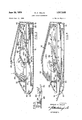
- FIG. 1 is a partially sectioned pictorial view of an open dispenser according to an embodiment of the present invention.
- FIG. 2 is an exploded view of the principal moving parts of the dispenser mechanism of FIG. 1.
- FIG. 3 is a cross-sectional view taken on the line 33 of FIG. 1 showing the pusher arm in a withdrawn position.
- FIG. 4 is a view similar to FIG. 3 showing the pusher arm in a forward position dispensing a sheet of paper from the dispenser.
- FIG. 5 is a small detailed view showing the elevated retaining position of the pusher head.
- the reference numeral 10 refers generally to a paper dispenser of a type which is particularly suitable for oflice desk use for supplying individual sheets of note paper or the like.
- the dispenser consists of a storage tray generally indicated by the reference numeral 12 which has a front or dispenser end 14, a pair of side walls 16 and a back wall 18.
- a plurality of sheets of paper 20 are stacked one upon the other and located within the tray 12.
- a pair of spaced support pillars 22 are located adjacent the back wall 18 of the tray and pivotably support a panel 24 which rests lightly upon the upper surface of the top sheet of paper which is in the the storage tray.
- the panel 24 may be formed with a recess and corner retaining lugs 26 to receive business cards, possibly identifying the source of supply of replacement sheets of note paper for use with the dispenser.
- the back wall 1 8 of the tray has an upwardly projecting portion 28 and the side walls 16 have notches 30 which serve to locate the tray relative to the cover 32.
- the cover 32 has a top wall 34, side walls 36 and a back wall 38.
- the internal dimensions of the cover defined by the side walls 36 and back wall 38 are suflicient to permit the cover to fit over the open top of the tray and the side walls .36 are each provided with lugs 40* which enter the notches 30 in the tray and the projection 28 of the back wall 18 of the tray extends upwardly into the cover when the tray and cover are in the assembled position wherein the shoulder 35 of the cover 32 rests on the upper edge 37 of the tray 12 as shown in FIGS. 3 and 4 of the drawings.
- a cover 32 has an opening 42 formed in the upper surface thereof and the outer end of a manually operable lever 44 projects through the opening 42.
- a pair of side walls 46 extend over a major portion of the length of the upper cover housing 32 and form a channel within which the lever 44 is mounted.
- Lever 44 is pivotably connected to the opposed channel walls 46 by a pivot pin 48 which is located adjacent to the back wall of the cover.
- the manually operable arm 44 is limited in its upward movement about the pivot pin 48 by the top wall of the cover 32 as shown in FIG. 4.
- the cover 32 has an extension or plat- 3 form 50 which extends inwardly from the dispensing end thereof to underlie the free end of the lever 44.
- a compression spring 52 is mounted on the platform 50 and retained thereon by a small projection 54 as shown in FIG. 1.
- the upper end of spring 52 presses against a lip 56 formed on the outer end of the manually operable lever 44 and is located by a small protruding pin 58 (FIG. 4).
- the manually operable lever 44 is pivotable about the pivot pin '48 and compresses the spring 52 when it is in the depressed position illustrated in FIG. 3. When the manual force is removed the spring 52 will reassert itself to return the lever 44 to the elevated position illustrated in FIG. 3.
- Side Walls 60 of the lever 44 are formed with teeth 62 formed on a pitch circle generated from the axis of the pivot pin 48 of the lever 44.
- the side walls 60 are formed with elongated slots 64 which extend longitudinally thereof and form a guide track for the reciprocating mechanism described below.
- the reciprocating mechanism comprises gear means 66, a carriage 68 and a pusher arm 70.
- the gear means 66 comprises a pair of toothed gears 72 which have journals 74 extending outwardly from opposite ends thereof.
- the gear means 66 also has a crank arm 76 which extends radially outwardly from the axis of rotation of the gears 72 to a pivot shaft 78.
- the carriage 68 has a pair of lugs '80- which are adapted to pivotably receive opposite ends of the shaft 78.
- a similar pair of lugs 84 are formed at the other end of the carriage 68 for receiving opposite ends of the shaft 86 formed at the upper end of the pusher arm 70.
- a recess 88 is formed between the lugs 84 sufiicient to provide clearance for the width of the arm 70.
- the pusher arm 7 has a pusher head 90 formed at the lower end thereof.
- the head 90 has an opening 92 formed in the upper surface thereof and a support bar 94 extending across the under surface thereof.
- the pusher pad 96 fits between the upper surface of head 90 and the bar 94.
- the pusher pad 96 is preferably made from a material such as rubber which has a high coefficient of friction when bearing against the paper in the storage tray.
- the journals 74 of the gears 72 are rotatably mounted in the side walls 46 of the top cover 32 and engage the teeth 62 formed in the manually movable arm 74.
- the shaft 78 fits within the lugs 80 to secure the carriage 68 to the outer end of a crank arm 76. Care should be taken to ensure that there is sufiicient clearance between the lever 44 and the outer end of crank arm 76 to permit the crank to pivot as the lever moves to the depressed position.
- the lugs 84 formed at the other end of the carriage 68 are pivotably connected to the shaft 86 which has a suflicient extent to extend into the oppositely disposed longitudinal slots 64 of lever 44.
- the arm 70 depends from the pivot shaft 86 which is slidable within the slots 64-.
- the manually operable arm 44 When the dispenser is not in use the manually operable arm 44 is in its elevated position and it is retained in this position by the spring 52 as previously described. In this position the head 90 of the pusher arm is in a forward position resting upon the top sheet of paper 20.
- the manually operable lever 44 To operate the dispensing device the manually operable lever 44 is pressed downwardly to the depressed position shown in FIG. 3 of the drawings. The downward motion of the lever 44 causes the teeth 62 thereof to rotate the gears 72. Rotation of the gears 72 causes the crank arm 78 to rotate about the axis of the gear 72 in the direction of the arrow indicated in FIG. 3. The rotational movement of the crank arm 78 transmits a reciprocating movement to the carriage 6-8 which causes the pivot bar 86 of the arm 70 to reciprocate in slots 64 in the lever 44. The movement of the upper end of the arm 70 causes movement of the head 90 in a direction away from the dispenser end of the tray to an inner or withdrawn position illustrated in FIG. 3.
- the head 90 of the pusher arm has a lip portion 91 extending outwardly therefrom.
- the lip portion 91 overlaps the inner edge of the platform 50 and thereby prevents the head 90 from falling downwardly into contact with the tray. It has been found that when the cover 32 and tray 12 are brought together with the pusher arm freely suspended from the pivot point 86 the pusher pad 96 will contact the top sheet of paper when the arm 70 is in an almost vertical position and as the cover and tray continue to move closer to one another the arm will pivot about axis '86 and move the pusher pad towards the dispenser end and automatically dispense the top sheet of paper. To prevent this from happening the lever arm may be depressed to the position shown in FIG.
- the arm 70 will be lowered automatically and will eventually remove the last sheet of paper and come to rest upon the bottom of the storage tray.
- the fact that the arm 70 is free to pivot about shaft 86 enables the dispenser head to operate successfully over a considerable range of thicknesses of stacks of paper in the storage tray.
- the improved dispenser will dispense a single sheet of paper from a stack of paper in response to a simple pressure applied to depress a manually operable lever 44. While the dispenser of the type described above is particularly suitable for use as a desk dispenser for dispensing small sheets of note paper the dispensing mechanism may be employed in a number of installations where it is required to dispense paper.
- the tray housing and dispensing mechanism are made from plastic material moulded to the required shape.
- the reciprocating mechanism may be modified to position the head of the pusher arm in the withdrawn position in its normal stationary position. The head would then move to the forward position in response to the depression of the manually operable lever 44 and return to the Withdrawn position when the manually operable lever 44 returns to the elevated position.
- This modification could be achieved quite simply by forming the teeth 62 on a portion of the lever arm on the opposite side of the gear 72 to cause the gear 72 to rotate in the opposite direction in response to the depression of the lever arm 44. This would have the effect of altering the reciprocating direction of the pusher arm with respect to the depression of the lever arm 44 as described above.
- a paper dispenser comprising: a storage tray for paper, said storage tray having a dispenser end, a paper pusher arm, supporting means for supporting said paper pusher over said tray, manually operable means for reciprocating said paper pusher to and fro over the tray between a withdrawn position and a forward position relative to said dispensing end of said tray to dispense paper from said dispenser, said manually operable means firstly moving said pusher from said forward position in which the pusher is at rest to said withdrawn position and secondly moving said pusher from said second position to said first position in a direction towards said dispensing end to dispense a sheet of paper from said dispensing end, said manually operable means including spring means urging said pusher to the position in which it is at rest, a manually operable lever operable against the force of said spring to move the pusher from the first position in which it is at rest to the second position, said spring means being adapted to reassert itself when the manual force is removed from said lever to return said pusher from said second position to said first position in which it
- said manually operable means includes spring means urging said pusher arm to the position in which it is at rest, a manually operable lever operable against the force of said spring to move the pusher from the first position in which it is at rest to the second position, said spring means being adapted to reassert itself when the manual force is removed from said lever to return said pusher from said second position to said first position in which it is at rest and a. crank arm extending radially outwardly from said gear means and pivotably connected at its outer enduto the end of said carriage which is slidably connected to said lever whereby rotational movement of said gear means transmits reciprocating movement to said carriage.
- a paper dispenser comprising: a storage tray for paper, said storage tray having a dispenser end, a paper pusher arm, supporting means for supporting said paper pusher over said tray, manually operable means for reciprocating said paper pusher to and fro over the tray between a withdrawn position and a forward position relative to said dispensing end of said tray to dispense paper from said' dispenser, said manually operable means including spring means urging said pusher arm to the position in which it is at rest, a manually operable lever operable against the force of said spring to move the pusher from the first position in which it is at rest to the second position, said spring means being adapted to reassert itself when the manual force is removed from said lever to return said pusher from said second position to said first position in which it is at rest, a carriage, said pusher being pivotably connected to said carriage, said manually operable lever being pivotably mounted in a housing, one end of said carriage being slidably connected to said lever, gear means carried by said housing and operable by movement of said lever, a crank arm
- a paper dispenser as claimed in claim 3, wherein said paper pusher comprises a pusher arm which is pivotably connected at its upper end to said manually operable means, said pusher arm havng a pusher head at the other end thereof, said pusher arm depending from said pivotably connected upper end into said tray to dispose said pusher head in contact with the paper in the tray.
- a paper dispenser comprising: a storage tray having a dispensing end, a housing adapted to co-operate with said storage tray to form a top cover thereof, a manually operable lever having one end pivotably connected to said housing, said lever being pivotable relative to said housing by manual movement of the other end thereof between a first elevated'position and a second depressed position, spring means engaging said lever and said housing urging said lever to said first elevated position, pinion means rotatably mounted in said housing, rack means carried by said lever and adapted to co-operate with said pinion to rotate said pinion in response to pivotal movement of said lever, a crank arm rigidly carried by said pinion and extending radially outwardly therefrom said crank arm having an outer end which is rotatable about the axis of said pinion in a predetermined arc, a reciprocating carriage, a first end of said carriage being slidably mounted in said lever and the second end of said carriage being pivotably connected to the outer end of said crank arm whereby rotation of said crank arm causes
Description
June 30, 1970 D. A. HILLIS DESK PAPER DISPENSER 2 Sheets-Sheet 1 Filed June 17, 1968 AT ORNE S United States Patent 3,517,855 DESK PAPER DISPENSER Donald A. Hillis, Willowdale, Ontario, Canada, assignor to Man-Mark Projects Limited, Toronto, Ontario,
Canada Filed June 17, 1968, Ser. No. 737,673 Int. Cl. B65g 59/00; B65h 3/02, G071 11/16 US. Cl. 221259 Claims ABSTRACT OF THE DISCLOSURE The present invention relates to a paper dispenser which is particularly suitable for use as a desk top dispenser for dispensing a single sheet of note paper or the like from a stack of sheets arranged one upon the other. The dispenser includes a storage tray for paper, a cover enclosing the storage tray and a dispenser mechanism adapted to dispense a single sheet of paper from the storage tray. The dispenser mechanism is actuated by manually depressing a single lever and then releasing the manual pressure. Depression of the manually operable lever indicates a reciprocating action of a pushing arm which is disposed above the paper in the storage tray and removal of the manual force from the lever completes the reciprocating action and causes a single sheet of paper to be dispensed from the dispenser.
FIELD OF THE INVENTION This invention relates to a paper dispenser which is adapted to dispense a single sheet of paper from a plurality of sheets stacked one upon the other.
PRIOR ART Paper dispensers for dispensing a single sheet of paper from a stack of sheets arranged one upon the other are well known and numerous mechanisms have been devised for controlling the dispensing action. The simplest and most common structure is a rotatable wheel carried by a shaft which extends transversely of the tray in which the paper is stacked. The wheel bears against the top sheet of paper and by rotating the drive shaft the top sheet is directed towards the discharge opening. Normally the shaft and wheel are free to move vertically in order to accommodate varying thicknesses of the stacks of sheets and consequently it is possible to lift the drive wheel away from the top sheet when attempting to rotate the drive shaft or to apply excessive pressure to the wheel. Insuflicient pressure causes the drive wheel to slip while excessive pressure causes more than one sheet to be disposed at a time from the dispenser. This difficulty arises frequently with the result that care must be taken by the operator when operating the apparatus.
SUMMARY OF INVENTION The present invention overcomes the difliculty of the prior art by providing an apparatus which does not require any careful manipulation on the part of the operator in order to dispense a sheet of paper.
According to an embodiment of the present invention a paper dispenser comprises a storage tray having a dispenser end, a pusher arm, support means for supporting the pusher arm over the tray and manually operable means for reciprocating the pusher arm to and fro over the tray between a withdrawn position and the forward position relative to the dispensing end of the tray to dispense paper from the dispenser.
According to a further embodiment of the present invention a dispenser comprises a storage tray for paper which has a dispenser end and a back end, a paper pusher arm, support means pivotably connected to the upper end ice of the paper pusher arm for supporting the arm over the tray and manually operable means for applying a reciprocating force to the paper pusher to move the paper pusher to and fro between a Withdrawn position wherein the lower end of the pusher is furthest removed from the dispenser and a forward position wherein the pusher is closest to the dispenser end of the tray. The pusher arm is downwardly inclined fromthe support means in a direction towards the dispenser end of the tray such that a component force of the reciprocating force is directed downwardly towards the tray to apply a dispensing force to the paper as the pusher arm moves from the with drawn position to the forward position.
The invention will 'be more clearly understood after reference to the following detailed specification read in conjunction with the drawings.
BRIEF DESCRIPTION OF DRAWINGS FIG. 1 is a partially sectioned pictorial view of an open dispenser according to an embodiment of the present invention.
FIG. 2 is an exploded view of the principal moving parts of the dispenser mechanism of FIG. 1.
FIG. 3 is a cross-sectional view taken on the line 33 of FIG. 1 showing the pusher arm in a withdrawn position.
FIG. 4 is a view similar to FIG. 3 showing the pusher arm in a forward position dispensing a sheet of paper from the dispenser.
FIG. 5 is a small detailed view showing the elevated retaining position of the pusher head.
Referring to the drawings it will be seen that the reference numeral 10 refers generally to a paper dispenser of a type which is particularly suitable for oflice desk use for supplying individual sheets of note paper or the like. The dispenser consists of a storage tray generally indicated by the reference numeral 12 which has a front or dispenser end 14, a pair of side walls 16 and a back wall 18. A plurality of sheets of paper 20 are stacked one upon the other and located within the tray 12. A pair of spaced support pillars 22 are located adjacent the back wall 18 of the tray and pivotably support a panel 24 which rests lightly upon the upper surface of the top sheet of paper which is in the the storage tray. The panel 24 may be formed with a recess and corner retaining lugs 26 to receive business cards, possibly identifying the source of supply of replacement sheets of note paper for use with the dispenser.
The back wall 1 8 of the tray has an upwardly projecting portion 28 and the side walls 16 have notches 30 which serve to locate the tray relative to the cover 32. The cover 32 has a top wall 34, side walls 36 and a back wall 38. The internal dimensions of the cover defined by the side walls 36 and back wall 38 are suflicient to permit the cover to fit over the open top of the tray and the side walls .36 are each provided with lugs 40* which enter the notches 30 in the tray and the projection 28 of the back wall 18 of the tray extends upwardly into the cover when the tray and cover are in the assembled position wherein the shoulder 35 of the cover 32 rests on the upper edge 37 of the tray 12 as shown in FIGS. 3 and 4 of the drawings.
A cover 32 has an opening 42 formed in the upper surface thereof and the outer end of a manually operable lever 44 projects through the opening 42. A pair of side walls 46 extend over a major portion of the length of the upper cover housing 32 and form a channel within which the lever 44 is mounted. Lever 44 is pivotably connected to the opposed channel walls 46 by a pivot pin 48 which is located adjacent to the back wall of the cover. The manually operable arm 44 is limited in its upward movement about the pivot pin 48 by the top wall of the cover 32 as shown in FIG. 4. The cover 32 has an extension or plat- 3 form 50 which extends inwardly from the dispensing end thereof to underlie the free end of the lever 44. A compression spring 52 is mounted on the platform 50 and retained thereon by a small projection 54 as shown in FIG. 1. The upper end of spring 52 presses against a lip 56 formed on the outer end of the manually operable lever 44 and is located by a small protruding pin 58 (FIG. 4). The manually operable lever 44 is pivotable about the pivot pin '48 and compresses the spring 52 when it is in the depressed position illustrated in FIG. 3. When the manual force is removed the spring 52 will reassert itself to return the lever 44 to the elevated position illustrated in FIG. 3.
Referring to FIG. 2 of the drawings it will be seen that the reciprocating mechanism comprises gear means 66, a carriage 68 and a pusher arm 70. The gear means 66 comprises a pair of toothed gears 72 which have journals 74 extending outwardly from opposite ends thereof. The gear means 66 also has a crank arm 76 which extends radially outwardly from the axis of rotation of the gears 72 to a pivot shaft 78. The carriage 68 has a pair of lugs '80- which are adapted to pivotably receive opposite ends of the shaft 78. A similar pair of lugs 84 are formed at the other end of the carriage 68 for receiving opposite ends of the shaft 86 formed at the upper end of the pusher arm 70. A recess 88 is formed between the lugs 84 sufiicient to provide clearance for the width of the arm 70. The pusher arm 7 has a pusher head 90 formed at the lower end thereof. The head 90 has an opening 92 formed in the upper surface thereof and a support bar 94 extending across the under surface thereof. The pusher pad 96 fits between the upper surface of head 90 and the bar 94. The pusher pad 96 is preferably made from a material such as rubber which has a high coefficient of friction when bearing against the paper in the storage tray.
Referring now to FIGS. 1, 3 and 4 it will be seen that the journals 74 of the gears 72 are rotatably mounted in the side walls 46 of the top cover 32 and engage the teeth 62 formed in the manually movable arm 74. The shaft 78 fits within the lugs 80 to secure the carriage 68 to the outer end of a crank arm 76. Care should be taken to ensure that there is sufiicient clearance between the lever 44 and the outer end of crank arm 76 to permit the crank to pivot as the lever moves to the depressed position. The lugs 84 formed at the other end of the carriage 68 are pivotably connected to the shaft 86 which has a suflicient extent to extend into the oppositely disposed longitudinal slots 64 of lever 44. The arm 70 depends from the pivot shaft 86 which is slidable within the slots 64-.
When the dispenser is not in use the manually operable arm 44 is in its elevated position and it is retained in this position by the spring 52 as previously described. In this position the head 90 of the pusher arm is in a forward position resting upon the top sheet of paper 20. To operate the dispensing device the manually operable lever 44 is pressed downwardly to the depressed position shown in FIG. 3 of the drawings. The downward motion of the lever 44 causes the teeth 62 thereof to rotate the gears 72. Rotation of the gears 72 causes the crank arm 78 to rotate about the axis of the gear 72 in the direction of the arrow indicated in FIG. 3. The rotational movement of the crank arm 78 transmits a reciprocating movement to the carriage 6-8 which causes the pivot bar 86 of the arm 70 to reciprocate in slots 64 in the lever 44. The movement of the upper end of the arm 70 causes movement of the head 90 in a direction away from the dispenser end of the tray to an inner or withdrawn position illustrated in FIG. 3.
Removal of the manual force which was applied to move the lever arm 44 permits the spring 52 to reassert itself and cause the arm 44 to move back to the original elevated position. The movement of the dispensing mechanism is reversed and the dispenser head moves from the inner position as shown in FIG. 3 to the outer position shown in FIG. 4. The reciprocating force which is applied to the shaft 86 in the returning action is diagrammatically represented by the arrow 98 and it Will be seen that this force will have a component diagrammatically represented by the arrow 100 which is directed towards the paper in the tray. The weight of the arm 70 and the head 90 also bear down upon the paper in the tray.
During the reciprocating movement of the arm 70 from the normal rest position to the withdrawn position illustrated in FIG. 3 the component force 100a of the reciprocating force 98a is directed away from the paper such that the head 90 will slide freely over the surface of the paper. Movement of the paper rearwardly of the tray is prevented by the end faces of the support brackets 22.
Referring to FIG. 5 of the drawings it will be seen that the head 90 of the pusher arm has a lip portion 91 extending outwardly therefrom. The lip portion 91 overlaps the inner edge of the platform 50 and thereby prevents the head 90 from falling downwardly into contact with the tray. It has been found that when the cover 32 and tray 12 are brought together with the pusher arm freely suspended from the pivot point 86 the pusher pad 96 will contact the top sheet of paper when the arm 70 is in an almost vertical position and as the cover and tray continue to move closer to one another the arm will pivot about axis '86 and move the pusher pad towards the dispenser end and automatically dispense the top sheet of paper. To prevent this from happening the lever arm may be depressed to the position shown in FIG. 3 and the dispenser inverted so that the arm 70 will fall away from the tray. The lever arm is then released, the spring 52 reasserts itself and the lip 91 is located over the platform 50 as shown in FIG. 5 and the head 96 is retained in this elevated position until the lever arm is again depressed.
It will be apparent from the foregoing description of the dispenser with reference to FIGS. 3 and 4 that as the level of the paper in the storage tray is lowered by the removal of successive sheets of paper, the arm 70 will be lowered automatically and will eventually remove the last sheet of paper and come to rest upon the bottom of the storage tray. The fact that the arm 70 is free to pivot about shaft 86 enables the dispenser head to operate successfully over a considerable range of thicknesses of stacks of paper in the storage tray. The improved dispenser will dispense a single sheet of paper from a stack of paper in response to a simple pressure applied to depress a manually operable lever 44. While the dispenser of the type described above is particularly suitable for use as a desk dispenser for dispensing small sheets of note paper the dispensing mechanism may be employed in a number of installations where it is required to dispense paper.
Preferably the tray housing and dispensing mechanism are made from plastic material moulded to the required shape.
Various modifications of the dispenser described above will be readily apparent to those skilled in the art without departing from the scope of the present invention. For example the reciprocating mechanism may be modified to position the head of the pusher arm in the withdrawn position in its normal stationary position. The head would then move to the forward position in response to the depression of the manually operable lever 44 and return to the Withdrawn position when the manually operable lever 44 returns to the elevated position. This modification could be achieved quite simply by forming the teeth 62 on a portion of the lever arm on the opposite side of the gear 72 to cause the gear 72 to rotate in the opposite direction in response to the depression of the lever arm 44. This would have the effect of altering the reciprocating direction of the pusher arm with respect to the depression of the lever arm 44 as described above.
What I claim is:
1. A paper dispenser comprising: a storage tray for paper, said storage tray having a dispenser end, a paper pusher arm, supporting means for supporting said paper pusher over said tray, manually operable means for reciprocating said paper pusher to and fro over the tray between a withdrawn position and a forward position relative to said dispensing end of said tray to dispense paper from said dispenser, said manually operable means firstly moving said pusher from said forward position in which the pusher is at rest to said withdrawn position and secondly moving said pusher from said second position to said first position in a direction towards said dispensing end to dispense a sheet of paper from said dispensing end, said manually operable means including spring means urging said pusher to the position in which it is at rest, a manually operable lever operable against the force of said spring to move the pusher from the first position in which it is at rest to the second position, said spring means being adapted to reassert itself when the manual force is removed from said lever to return said pusher from said second position to said first position in which it is at rest, said manually operable means also including a carriage, said pusher arm being pivotably connected to said carriage, said manually operable lever being pivotably mounted in a housing, one end of said carriage being slidably connected to said lever, gear means carried by said housing and operable by movement of said lever to cause said carriage to reciprocate within its slidable mounting within said lever whereby said pusher is caused to reciprocate between said first and second positions in response to sliding movement of the carriage.
2. A paper dispenser as claimed in claim 1, wherein said manually operable means includes spring means urging said pusher arm to the position in which it is at rest, a manually operable lever operable against the force of said spring to move the pusher from the first position in which it is at rest to the second position, said spring means being adapted to reassert itself when the manual force is removed from said lever to return said pusher from said second position to said first position in which it is at rest and a. crank arm extending radially outwardly from said gear means and pivotably connected at its outer enduto the end of said carriage which is slidably connected to said lever whereby rotational movement of said gear means transmits reciprocating movement to said carriage.
3. A paper dispenser comprising: a storage tray for paper, said storage tray having a dispenser end, a paper pusher arm, supporting means for supporting said paper pusher over said tray, manually operable means for reciprocating said paper pusher to and fro over the tray between a withdrawn position and a forward position relative to said dispensing end of said tray to dispense paper from said' dispenser, said manually operable means including spring means urging said pusher arm to the position in which it is at rest, a manually operable lever operable against the force of said spring to move the pusher from the first position in which it is at rest to the second position, said spring means being adapted to reassert itself when the manual force is removed from said lever to return said pusher from said second position to said first position in which it is at rest, a carriage, said pusher being pivotably connected to said carriage, said manually operable lever being pivotably mounted in a housing, one end of said carriage being slidably connected to said lever, gear means carried by said housing and operable by movement of said lever, a crank arm extending radially outwardly from said gear means and pivotably connected at its outer end to the other end of said'carriage whereby rotational movement of said gear means transmits reciprocating movement to said carriage which in turn causes said pusher to reciprocate.
4. A paper dispenser as claimed in claim 3, wherein said paper pusher comprises a pusher arm which is pivotably connected at its upper end to said manually operable means, said pusher arm havng a pusher head at the other end thereof, said pusher arm depending from said pivotably connected upper end into said tray to dispose said pusher head in contact with the paper in the tray.
5. A paper dispenser comprising: a storage tray having a dispensing end, a housing adapted to co-operate with said storage tray to form a top cover thereof, a manually operable lever having one end pivotably connected to said housing, said lever being pivotable relative to said housing by manual movement of the other end thereof between a first elevated'position and a second depressed position, spring means engaging said lever and said housing urging said lever to said first elevated position, pinion means rotatably mounted in said housing, rack means carried by said lever and adapted to co-operate with said pinion to rotate said pinion in response to pivotal movement of said lever, a crank arm rigidly carried by said pinion and extending radially outwardly therefrom said crank arm having an outer end which is rotatable about the axis of said pinion in a predetermined arc, a reciprocating carriage, a first end of said carriage being slidably mounted in said lever and the second end of said carriage being pivotably connected to the outer end of said crank arm whereby rotation of said crank arm causes said second end of said carriage to reciprocate in said lever, a paper pusher arm pivotably connected at its upper end to said first end of said carriage and adapted to reciprocate therewith, said paper pusher arm depending from said upper end thereof to a lower end which extends into the tray to bear against the upper surface of paper in said tray whereby manual movement of said manually operable lever means from said first elevation position to said second depressed position moves the lower end of said pusher arm away from said dispenser end of said tray and the movement of said lever from said depressed position to said elevated position by said spring means moves the lower end of said pusher towards said dispenser end to dispense paper from the dispenser.
References Cited UNITED STATES PATENTS 1,151,792 8/1915 Jaeger 221-275 1,446,285 2/1923 Bartlett 221-259 2,727,655 12/ 1955 Pearce 221-259 2,783,042 2/ 1957 Picking 271-42 EDWARD SROKA, Primary Examiner US. Cl. X.R. 271-42
Applications Claiming Priority (1)
| Application Number | Priority Date | Filing Date | Title |
|---|---|---|---|
| US73767368A | 1968-06-17 | 1968-06-17 |
Publications (1)
| Publication Number | Publication Date |
|---|---|
| US3517855A true US3517855A (en) | 1970-06-30 |
Family
ID=24964833
Family Applications (1)
| Application Number | Title | Priority Date | Filing Date |
|---|---|---|---|
| US737673A Expired - Lifetime US3517855A (en) | 1968-06-17 | 1968-06-17 | Desk paper dispenser |
Country Status (1)
| Country | Link |
|---|---|
| US (1) | US3517855A (en) |
Cited By (18)
| Publication number | Priority date | Publication date | Assignee | Title |
|---|---|---|---|---|
| US4071165A (en) * | 1975-12-29 | 1978-01-31 | Norbert Leopoldi | Paper dispenser having a frictional discharge assistant |
| US4865223A (en) * | 1988-05-18 | 1989-09-12 | Glory Formosa Co., Ltd. | Device for organizing disk implements and dispensing single sheets of paper |
| WO2002055008A2 (en) * | 2000-12-29 | 2002-07-18 | Capitol Insulated Products, Inc. | Meter strip dispenser assembly |
| US6595387B1 (en) | 2002-01-28 | 2003-07-22 | Harold M. Zimmerman | Dispenser for sheets such as note pad paper |
| US20050133524A1 (en) * | 2003-11-24 | 2005-06-23 | L'oreal | Device for packaging and dispensing stacked items, in particular cosmetics on a medium |
| FR2879573A1 (en) * | 2004-12-21 | 2006-06-23 | Airsec Soc Par Actions Simplif | DEVICE FOR DISPENSING THE UNIT OF OBJECTS PRESENTED IN THE FORM OF THIN SHEETS OR STRIPES |
| US20060266759A1 (en) * | 2005-05-27 | 2006-11-30 | Tramontina Paul F | Restrictor and dispensing system |
| US20070034630A1 (en) * | 2003-03-03 | 2007-02-15 | Didier Lancesseur | Device for dispensing oblong objects, comprising one main opening and at least one other elongated opening |
| US20070215635A1 (en) * | 2006-03-20 | 2007-09-20 | Kimberly-Clark Worldwide, Inc. | Dispenser Assembly For Dispensing Gloves Including A Cartridge And A Dispenser With A Glove Pusher |
| US20070215628A1 (en) * | 2006-03-20 | 2007-09-20 | Paul Francis Tramontina | Dispenser Assembly For Dispensing Gloves Including Glove Positioner |
| US20070269401A1 (en) * | 2006-05-19 | 2007-11-22 | Airsec S.A.S. | Device for Distributing and/or Controlling the Discharge of Unitary Products, Fitted Onto a Container, and For the In-Situ Treatment of its Internal Atmosphere |
| US20070267304A1 (en) * | 2006-05-19 | 2007-11-22 | Airsec S.A.S. | Sealed assembly for storage and distribution with discharge control for solid pharmaceutical products |
| US20080041875A1 (en) * | 2004-03-30 | 2008-02-21 | Didier Lancesseur | Device for the Single-Unit Dispensing of Shaped Objects, Such as Pharmaceutical Tablets |
| US7661555B1 (en) * | 2002-12-13 | 2010-02-16 | Union Street Brand Packaging | Single dispensing film strip container |
| US8875919B2 (en) | 2010-06-08 | 2014-11-04 | Clariant Production (France) Sas | Stopper for closing a dispensing opening of a container |
| US9823234B2 (en) | 2013-02-04 | 2017-11-21 | Clariant Production (France) S.A.S. | Dispensing device for holding and dispensing strip-like objects |
| US20180338650A1 (en) * | 2017-05-24 | 2018-11-29 | The Clorox Company | On demand wet wipe dispensing device |
| US11198072B2 (en) | 2017-08-14 | 2021-12-14 | GW Development UK Limited | Toy device for dispensing stackable or rollable materials and related methods |
Citations (4)
| Publication number | Priority date | Publication date | Assignee | Title |
|---|---|---|---|---|
| US1151792A (en) * | 1914-08-12 | 1915-08-31 | Ind Service Company | Dispensing apparatus. |
| US1446285A (en) * | 1922-07-27 | 1923-02-20 | Bar Trex Mfg Co Inc | Device for feeding paper slips |
| US2727655A (en) * | 1953-12-02 | 1955-12-20 | Pearce Howard Reginald | Device for dispensing single sheets of paper and the like |
| US2783042A (en) * | 1953-01-21 | 1957-02-26 | Gestetner Ltd | Sheet feeding mechanisms |
-
1968
- 1968-06-17 US US737673A patent/US3517855A/en not_active Expired - Lifetime
Patent Citations (4)
| Publication number | Priority date | Publication date | Assignee | Title |
|---|---|---|---|---|
| US1151792A (en) * | 1914-08-12 | 1915-08-31 | Ind Service Company | Dispensing apparatus. |
| US1446285A (en) * | 1922-07-27 | 1923-02-20 | Bar Trex Mfg Co Inc | Device for feeding paper slips |
| US2783042A (en) * | 1953-01-21 | 1957-02-26 | Gestetner Ltd | Sheet feeding mechanisms |
| US2727655A (en) * | 1953-12-02 | 1955-12-20 | Pearce Howard Reginald | Device for dispensing single sheets of paper and the like |
Cited By (31)
| Publication number | Priority date | Publication date | Assignee | Title |
|---|---|---|---|---|
| US4071165A (en) * | 1975-12-29 | 1978-01-31 | Norbert Leopoldi | Paper dispenser having a frictional discharge assistant |
| US4865223A (en) * | 1988-05-18 | 1989-09-12 | Glory Formosa Co., Ltd. | Device for organizing disk implements and dispensing single sheets of paper |
| US7063234B2 (en) | 2000-12-29 | 2006-06-20 | Csp Technologies, Inc. | Meter strip dispenser assembly |
| WO2002055008A2 (en) * | 2000-12-29 | 2002-07-18 | Capitol Insulated Products, Inc. | Meter strip dispenser assembly |
| US20020104849A1 (en) * | 2000-12-29 | 2002-08-08 | Jean-Pierre Giruad | Meter strip dispenser assembly |
| WO2002055008A3 (en) * | 2000-12-29 | 2003-08-21 | Capitol Insulated Products Inc | Meter strip dispenser assembly |
| US6595387B1 (en) | 2002-01-28 | 2003-07-22 | Harold M. Zimmerman | Dispenser for sheets such as note pad paper |
| US7661555B1 (en) * | 2002-12-13 | 2010-02-16 | Union Street Brand Packaging | Single dispensing film strip container |
| US7628292B2 (en) | 2003-03-03 | 2009-12-08 | Airsec S.A. | Device for dispensing oblong objects, comprising one main opening and at least one other elongated opening |
| US20070034630A1 (en) * | 2003-03-03 | 2007-02-15 | Didier Lancesseur | Device for dispensing oblong objects, comprising one main opening and at least one other elongated opening |
| US7287666B2 (en) * | 2003-11-24 | 2007-10-30 | L'oreal | Device for packaging and dispensing stacked items, in particular cosmetics on a medium |
| US20050133524A1 (en) * | 2003-11-24 | 2005-06-23 | L'oreal | Device for packaging and dispensing stacked items, in particular cosmetics on a medium |
| US7810673B2 (en) | 2004-03-30 | 2010-10-12 | Airsec | Device for the single-unit dispensing of shaped objects, such as pharmaceutical tablets |
| US20080041875A1 (en) * | 2004-03-30 | 2008-02-21 | Didier Lancesseur | Device for the Single-Unit Dispensing of Shaped Objects, Such as Pharmaceutical Tablets |
| WO2006067334A1 (en) * | 2004-12-21 | 2006-06-29 | Airsec (Societe Par Actions Simplifiee) | Device for storing and dispensing in single-units objects in the form of sheets or thin strips |
| FR2879573A1 (en) * | 2004-12-21 | 2006-06-23 | Airsec Soc Par Actions Simplif | DEVICE FOR DISPENSING THE UNIT OF OBJECTS PRESENTED IN THE FORM OF THIN SHEETS OR STRIPES |
| US20090302048A1 (en) * | 2004-12-21 | 2009-12-10 | Airsec | Device for storing and dispensing in single units objects in the form of sheets or thin strips |
| US20060266759A1 (en) * | 2005-05-27 | 2006-11-30 | Tramontina Paul F | Restrictor and dispensing system |
| US7591396B2 (en) * | 2005-05-27 | 2009-09-22 | Kimberly-Clark Worldwide, Inc. | Restrictor and dispensing system |
| US20070215628A1 (en) * | 2006-03-20 | 2007-09-20 | Paul Francis Tramontina | Dispenser Assembly For Dispensing Gloves Including Glove Positioner |
| US7699189B2 (en) | 2006-03-20 | 2010-04-20 | Kimberly-Clark Worldwide, Inc. | Dispenser assembly for dispensing gloves including glove positioner |
| US7731056B2 (en) * | 2006-03-20 | 2010-06-08 | Kimberly-Clark Worldwide, Inc. | Dispenser assembly for dispensing gloves including a cartridge and a dispenser with a glove pusher |
| US20070215635A1 (en) * | 2006-03-20 | 2007-09-20 | Kimberly-Clark Worldwide, Inc. | Dispenser Assembly For Dispensing Gloves Including A Cartridge And A Dispenser With A Glove Pusher |
| US20070267304A1 (en) * | 2006-05-19 | 2007-11-22 | Airsec S.A.S. | Sealed assembly for storage and distribution with discharge control for solid pharmaceutical products |
| US20070269401A1 (en) * | 2006-05-19 | 2007-11-22 | Airsec S.A.S. | Device for Distributing and/or Controlling the Discharge of Unitary Products, Fitted Onto a Container, and For the In-Situ Treatment of its Internal Atmosphere |
| US7780008B2 (en) | 2006-05-19 | 2010-08-24 | Airsec S.A.S. | Sealed assembly for storage and distribution with discharge control for solid pharmaceutical products |
| US8875919B2 (en) | 2010-06-08 | 2014-11-04 | Clariant Production (France) Sas | Stopper for closing a dispensing opening of a container |
| US9823234B2 (en) | 2013-02-04 | 2017-11-21 | Clariant Production (France) S.A.S. | Dispensing device for holding and dispensing strip-like objects |
| US20180338650A1 (en) * | 2017-05-24 | 2018-11-29 | The Clorox Company | On demand wet wipe dispensing device |
| US10478022B2 (en) * | 2017-05-24 | 2019-11-19 | The Clorox Company | On demand wet wipe dispensing device |
| US11198072B2 (en) | 2017-08-14 | 2021-12-14 | GW Development UK Limited | Toy device for dispensing stackable or rollable materials and related methods |
Similar Documents
| Publication | Publication Date | Title |
|---|---|---|
| US3517855A (en) | Desk paper dispenser | |
| AU770219B2 (en) | Ticket dispensing mechanism | |
| US5076466A (en) | Folded sheet product dispenser with anti-overfill mechanism | |
| US5044622A (en) | Apparatus for automatically dispensing objects | |
| US5456420A (en) | Rolled tissue dispenser | |
| US3260402A (en) | Sheet dispensing device | |
| US5842598A (en) | Combination storage system and compact ejection mechanisms | |
| US6102248A (en) | Card type structures | |
| US6652173B1 (en) | Ticket dispensing mechanism | |
| US4008119A (en) | Labelling device | |
| US4000831A (en) | Sliced bread dispenser | |
| US3168212A (en) | Dispensing apparatus for horizontally disposed articles | |
| US3912124A (en) | Single copy newsstand vendor | |
| US2122637A (en) | Paper dispenser | |
| KR950010065B1 (en) | Spreading devices of toilet-towel dispenses | |
| US1621960A (en) | Vending machine | |
| US2303520A (en) | Dispenser for rolled sheet material | |
| US3833148A (en) | Bread dispenser | |
| US2334458A (en) | Label handling apparatus | |
| US3008606A (en) | Device for storing and dispensing sheets of copying paper | |
| US3119520A (en) | Dispenser which presents a cigarette in an erect position | |
| US6102250A (en) | Lever operated device for dispensing cards | |
| US3036751A (en) | Apparatus for removing as required, tear-off pieces, particularly postage stamps | |
| US1250790A (en) | Strip-serving apparatus. | |
| US2008592A (en) | Automatic box moving means for lidding machines |