US3402697A - Film thickness control for electrostatic coating systems - Google Patents
Film thickness control for electrostatic coating systems Download PDFInfo
- Publication number
- US3402697A US3402697A US618237A US61823767A US3402697A US 3402697 A US3402697 A US 3402697A US 618237 A US618237 A US 618237A US 61823767 A US61823767 A US 61823767A US 3402697 A US3402697 A US 3402697A
- Authority
- US
- United States
- Prior art keywords
- guns
- gun
- spray
- array
- work
- Prior art date
- Legal status (The legal status is an assumption and is not a legal conclusion. Google has not performed a legal analysis and makes no representation as to the accuracy of the status listed.)
- Expired - Lifetime
Links
Images
Classifications
-
- B—PERFORMING OPERATIONS; TRANSPORTING
- B05—SPRAYING OR ATOMISING IN GENERAL; APPLYING FLUENT MATERIALS TO SURFACES, IN GENERAL
- B05B—SPRAYING APPARATUS; ATOMISING APPARATUS; NOZZLES
- B05B5/00—Electrostatic spraying apparatus; Spraying apparatus with means for charging the spray electrically; Apparatus for spraying liquids or other fluent materials by other electric means
- B05B5/08—Plant for applying liquids or other fluent materials to objects
- B05B5/087—Arrangements of electrodes, e.g. of charging, shielding, collecting electrodes
-
- B—PERFORMING OPERATIONS; TRANSPORTING
- B05—SPRAYING OR ATOMISING IN GENERAL; APPLYING FLUENT MATERIALS TO SURFACES, IN GENERAL
- B05B—SPRAYING APPARATUS; ATOMISING APPARATUS; NOZZLES
- B05B13/00—Machines or plants for applying liquids or other fluent materials to surfaces of objects or other work by spraying, not covered by groups B05B1/00 - B05B11/00
- B05B13/02—Means for supporting work; Arrangement or mounting of spray heads; Adaptation or arrangement of means for feeding work
- B05B13/04—Means for supporting work; Arrangement or mounting of spray heads; Adaptation or arrangement of means for feeding work the spray heads being moved during spraying operation
- B05B13/0447—Installation or apparatus for applying liquid or other fluent material to conveyed separate articles
-
- B—PERFORMING OPERATIONS; TRANSPORTING
- B05—SPRAYING OR ATOMISING IN GENERAL; APPLYING FLUENT MATERIALS TO SURFACES, IN GENERAL
- B05B—SPRAYING APPARATUS; ATOMISING APPARATUS; NOZZLES
- B05B13/00—Machines or plants for applying liquids or other fluent materials to surfaces of objects or other work by spraying, not covered by groups B05B1/00 - B05B11/00
- B05B13/02—Means for supporting work; Arrangement or mounting of spray heads; Adaptation or arrangement of means for feeding work
- B05B13/04—Means for supporting work; Arrangement or mounting of spray heads; Adaptation or arrangement of means for feeding work the spray heads being moved during spraying operation
- B05B13/0463—Installation or apparatus for applying liquid or other fluent material to moving work of indefinite length
- B05B13/0468—Installation or apparatus for applying liquid or other fluent material to moving work of indefinite length with reciprocating or oscillating spray heads
Definitions
- An electrostatic coating apparatus for controlling the thickness and uniformity of the coating deposited on a workpiece.
- a linear array of a plurality of uniformly charged electrostatic spray guns are mounted on a reciprocable stem and an electrode is provided on said stem at each side of said array, spaced from the adjacent gun at a distance substantially equal to the spacing between adjacent spray guns and charged to the same potential, the ends of the electrodes being spaced from the work at substantially the same distance as the discharge ends of said spray guns.
- This invention relates to a film thickness control for electrostatic coating systems and has for its primary obcoating an extensive workpiece, as for example, a long panel suspended from an overhead, horizontally moving conveyor, it has been found that it is necessary to use a plurality of spray guns in an array.
- This expedient is adopted because the rate of material flow through a single electrostatic spray gun is somewhat limited for highest efficiency and if it were attempted to cover the entire workpiece with one gun, it would be necessary to operate the conveyor at an intolerably low rate of travel, and to reciprocate the gun vertically through a stroke substantially equal to the height of the workpiece.
- an array of a plurality of electrostatic spray guns is used, more material can be deposited in a unit of time and the conveyor speed can be increased to a satisfactory, conventional value.
- the association of a plurality of electrostatic spray guns in an array leads to problems in obtaining uniformity of the film thickness, or the thickness of material applied to thejworkpiece, whether or not the array is reciprocated. If the array is reciprocated, more uniform deposition can be obtained than without the movement.
- the present invention relates to a means to control the film thickness deposited by an array of electrostatic spray guns and finds its highest use where the array is reciprocated, but will also be found to improve the uniformity of the deposition from even a stationary array.
- the variation in film thickness, or the thickness of a deposited coating of paint for example, be quite uniform Over the entire coated area.
- the film thickness uniformity is expressed as a percentage or ratio between the thickest and thinnest parts of the coated areas. For example, if the thickest coated area is measured and found to have a coating of 0.010 in thickness, and thinnest area is measured and found to have a deposited coating of 0.0075", the uniformity is said to be 75 percent. In practice, 70 percent uniformity is considered to be acceptable, and a uniformity of 80 percent is excellent.
- the spray pattern of a spray gun is influenced and may be drastically affected by the presence of neighboring similarly charged apparatus. For example, if a single spray gun has a round deposition pattern, the association therewith of a like gun will cause a distortion of the pattern of each gun into a non-circular configuration that trails oil? into a sparse spray on the side removed from the neighboring gun, and that is somewhat more dense in the areas between the spray guns.
- the resulting combined pattern has a pronounced tendency to be thicker in the central areas and thinner at the outside areas to the point where the coating thickness uniformity will be measured at less than the desired value.
- the present invention is based on the discovery that the combined patterns of a plurality of electrostatic spray guns can be made uniform to an unexpectedly high degree by introducing into the electrostatic field at each end of the array of a plurality of spray guns, a field modifying or compressing electrode charged to the same polarity as the charging electrodes of the spray guns themselves.
- the field modifying electrodes may carry a lower or higher potential than the spray guns themselves, depending on the degree of pattern correction and compression that may be desired for a given workpiece, and may be energized from the same power source as the spray guns themselves, or from a different power source.
- the spacing of electrostatically charged guns within the array is uniform, the guns are charged to the same potential, and the spacing between the end guns and the field modifying electrodes is substantially equal to the spacing between guns, the electrodes being charged to the same potential and the same polarity as the guns themselves.
- the compressing effect on the spray deposition pattern of the gun adjacent the electrode will be substantially the same as the compressing effect on said pattern produced by the neighboring spray gun in the array.
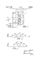
- FIG. 1 is a diagrammatic view of an array of electrostatic spray guns embodying the present invention
- PIG. 2 is a graph of film thickness or film cross section of deposited coatings from an array of three electrostatically charged spray guns without the modifying electrodes provided by the present invention.
- FIG. 3 is a graph similar to FIG. 2 indicating the film cross section resulting from the present invention.
- 10a, 10b and designate electrostatically charged spray guns of the type in which the spray gun itself, or an electrode carried by the spray gun, is brought to a high potential, for example 60 kv. to kv., preferably negative with respect to ground.
- Particles of coating material issuing from the gun acquire a high negative charge and are deposited on a grounded workpiece W under the influence of the electrostatic field which exists between the gun and the work.
- a positive charge may be placed on the gun and thus on the particles and further, the work may be at other than ground potential as is well known in the art. It will be assumed for purposes of this description that the spray pattern of a single spray gun is essentially circular.
- the spray gun may be reciprocated to deposit a band of coating material that may be acceptably uniform in cross section.
- the work W is moved laterally on a conveyor across the space in front of the gun while the gun is reciprocating vertically the entire panel will become coated with a layer of material that should be essentially uniform in thickness.
- the rate of reciprocation and the rate of lateral traverse are so related that the gun makes several vertical passes across the work during the time taken for the conveyor to traverse a distance equal to the width of the pattern.
- Electrostatic spray guns are limited in the quantity of coating material that can be satisfactorily atomized, charged and deposited in any given period of time. This quantity of material and the area of work to be coated determine the speed at which a conveyor carrying the work can be operated. For this reason, among others, it is frequently necessary to employ an array of two or more electrostatically charged guns.
- the present invention is applicable to any array, but is particularly useful Where three or more guns are associated as a linearly arranged group. The benefits of the invention will be most pronounced when the array of guns is reciprocated so that the combined spray sweeps across the work in a direction transverse to the direction of conveyor movement.
- the spray guns 10a, 10b and 100 are mounted in any suitable manner on a stem 11.
- the spacing d between guns can be assumed to be adjustable for purposes which will become apparent.
- the stem 11 is supported at its top and bottom by insulating arms 12 and 13 which are pivoted to the steam and to a common frame 14.
- One of the arms 13 is extended rearwardly of the frame 14 and is driven to its reciprocating motion by an eccentric 15 powered by a motor 16 and connected to the arm 13 by a connecting rod 17.
- the spray guns 10a, 10b and 100 may be of any suitable type since the present invention is applicable to any electrostatic coating system whether the coating material is atomized by mechanical or electrostatic force.
- the diagrammatic showing in FIG. 1 indicates guns of the type in which liquid coating material is supplied to each gun through a flexible hose or tube 18 and air is supplied through a flexible hose or tube 19 and is used to atomize the liquid and to operate the on-oif control cylinder within the gun itself.
- Air operated and air atomizing spray guns are, of course, well known in the art.
- the guns themselves are charged from a power pack E, one side of which is grounded and the opposite terminal of which carries a negative charging voltage, -V.
- the electrostatic field from each gun may be intensified by the introduction of a central, needle-like electrode disposed in or closely adjacent to the nozzle of the gun where air atomization first takes place.
- the electrostatic field originating in each gun has a decided distorting effect on the field of its neighbors.
- the field intensity is preferably very high in the areas where the coating material, if it is liquid, is broken up into droplets or atomized. The atomized particles will thus acquire, by ionic bombardment, the high charge that is requisite for efiicient deposition of the atomized particles on the work.
- FIG. 2 shows diagrammatically the inequality of the film thickness to be expected.
- the abscissa represents film thickness, greatly expanded, and the ordinate represents lineal distance from end to end of the array of guns or a vertical dimension in the orientation of the parts shown in FIG. 1.
- the results are those obtained from vertically reciprocating an array of three spray guns in front of a moving workpiece suspended on a conveyor and moving laterally with respect to the direction of spray projection.
- the three solid line curves 20, 21 and 22 show the contribution to the total film thickness made by each of the electrostatic spray guns charged to like potential, uniformly spaced and having the same quantity of coating material supplied to each. Thus the areas under the three curves are equal because they represent equal volumes of deposited material.
- the dash line 23 indicates the total film thickness and is the arithmetic sum of curves 20, 21 and 22.
- the curves 20, 21 and 22 are taken with the stem 11 reciprocating through a path having a maximum lineal dimension approximately equal to the spacing distance between guns. It has been found that this spacing and reciprocating stroke length are essentially optimum although variations therein may be tolerated and may, in fact, be dictated by the characteristics of the work to be coated.
- the film thickness variation shown in FIG. 2 would probably not be commercially acceptable, even though the efliciency of the deposition of the entire electrostatic coating system may be quite high. Too much of the liquid coating material appears in the center area of the work panel and too little is deposited in the outer areas.
- the center line of the coated work-piece is designated C in FIG. 2.
- the present invention makes it possible to provide a multiple spray gun array in which the uniformity of deposition is greatly improved.
- each gun may be made to have a similar pattern, and the film thickness uniformity of the deposition from the array may be made to exceed percent. That is, no area of the work panel W will have a deposited film that is less than 80 percent of the maximum thickness of the film on any portion of the panel.
- Each electrode 30 may comprise, for example, a simple rod-like element having a sharp point. The electrode should be such that it will exert the same field influence as one of the spray guns in the array.
- the location of the field modifying electrodes 30 may be varied, but in the preferred execution of the invention, the electrode geometry and spacing is such that the electrostatic field emanating from the electrode 30 influences or compresses the pattern of the adjacent electrostatic spray gun in substantially the same manner and to substantially the same extent as the pattern is influenced by the field of the neighboring gun in the array.
- the same spacing d would be utilized between spray gun 10a and the up per field modifying electrode 30, and the same spacing d would be used between the lower spray gun 10c and the lower of the field modifying electrodes 30.
- the spacing between the end of the electrode and the work W would be the same as the spacing between the charging electrode of the spray guns and the work. It is, of course, apparent that the electrodes 30 may, therefore, be most easily charged from the power pack E to the voltage V to which the spray guns are charged. If, for any reason, it is necessary to apply a higher or lower charging voltage to the electrodes 30, it may be necessary to use a separate power pack for this purpose.
- the voltage on the field modifying electrodes 30 may be reduced in view of the lower electrode-work spacing that occurs by reason of the configuration of the work.
- FIG. 3 diagrammatically indicates the effect of the presence of the field modifying electrodes 30.
- each of the spray guns a, 10b and 10c in this instance, when reciprocated, deposits coating material in a similar pattern and the film thickness of the spray from each of the three guns is designated 31, 32 and 33.
- the contribution to the film on the work of each of the spray guns is indicated as essentially the same, and the sum of the three separate films is essentially a flat, straight line as indicated by the dashed line 34, which is the arithmetic sum of the increments 31, 32 and 33 deposited by the separate spray guns.
- C designates the center of the coated area of the work.
- the overlap of the pattern from the spray guns with respect to the edge of the article to be coated should be controlled. If the overlap is too great, paint will be lost by spraying beyond the article, and if the edge is sharp, there is a tendency for the paint to build up to an excessive thickness at the sharp corner. Therefore, the end gun at the top and bottom of the array should be spaced inwardly towards the center of the work panel when it stands at the mid-point of its reciprocating stroke, by a distance about equal to one-half of the stroke length.
- Electrostatic coating apparatus comprising a reciprocable stem, a linear array of a plurality of uniformly spaced uniformly charged electrostatic spray guns mounted on said stern and having their discharge ends substantially uniformly spaced from the median plane of the work to -be coated, and an electrode mounted on said stem at each end of said array spaced from the adjacent gun a distance substantially equal to the spacing between adjacent spray guns and charged in the same polarity as said adjacent gun and to the same potential, the ends of said electrodes being spaced from the work at substantially the same distance as the discharge ends of said spray guns, whereby each of said electrodes is effective to influence the deposition pattern of its adjacent gun in substantially the same manner and to substantially the same extent as said pattern is influenced by the presence of the neighboring gun in said array, and means to reciprocate said stem and the array of spray guns and electrodes carried thereby.
- Electrostatic coating apparatus in accordance with claim 1 in which said last means operates to reciprocate said stem and said array of spray guns and electrodes through a distance substantially equal to the spacing distance between adjacent guns.
- PETER FELDMAN Primary Examiner.
Description
Sept. 24, 1968 E. KOCK 3,402,697
FILM THICKNESS CONTROL FOR ELECTROSTATIC COATING SYSTEMS,
Original Filed March 13, 1964 FILM THICKNES:
INVENTOR: .Z'RHAHD Km :14:
MTQW United States Patent 3,402,697 FILM THICKNESS CONTROL FQR ELECTRO- STATIC COATING SYSTEMS Erhard Kock, Toledo, Ohio, assignor to The DeVilbiss Company, Toledo, Ohio, a corporation of Ohio Continuation of application Ser. No. 351,666, Mar. 13,
1964. This application Feb. 23, 1967, Ser. No. 618,237
2 Claims. (Cl. 118624) ABSTRACT OF THE DISCLOSURE An electrostatic coating apparatus for controlling the thickness and uniformity of the coating deposited on a workpiece. A linear array of a plurality of uniformly charged electrostatic spray guns are mounted on a reciprocable stem and an electrode is provided on said stem at each side of said array, spaced from the adjacent gun at a distance substantially equal to the spacing between adjacent spray guns and charged to the same potential, the ends of the electrodes being spaced from the work at substantially the same distance as the discharge ends of said spray guns.
This is a continuation of application Ser. No. 351,666, filed Mar. 13, 1964.
This invention relates to a film thickness control for electrostatic coating systems and has for its primary obcoating an extensive workpiece, as for example, a long panel suspended from an overhead, horizontally moving conveyor, it has been found that it is necessary to use a plurality of spray guns in an array. This expedient is adopted because the rate of material flow through a single electrostatic spray gun is somewhat limited for highest efficiency and if it were attempted to cover the entire workpiece with one gun, it would be necessary to operate the conveyor at an intolerably low rate of travel, and to reciprocate the gun vertically through a stroke substantially equal to the height of the workpiece. When an array of a plurality of electrostatic spray guns is used, more material can be deposited in a unit of time and the conveyor speed can be increased to a satisfactory, conventional value.
The association of a plurality of electrostatic spray guns in an array, however, leads to problems in obtaining uniformity of the film thickness, or the thickness of material applied to thejworkpiece, whether or not the array is reciprocated. If the array is reciprocated, more uniform deposition can be obtained than without the movement. The present invention relates to a means to control the film thickness deposited by an array of electrostatic spray guns and finds its highest use where the array is reciprocated, but will also be found to improve the uniformity of the deposition from even a stationary array.
It is desirable that the variation in film thickness, or the thickness of a deposited coating of paint, for example, be quite uniform Over the entire coated area. The film thickness uniformity is expressed as a percentage or ratio between the thickest and thinnest parts of the coated areas. For example, if the thickest coated area is measured and found to have a coating of 0.010 in thickness, and thinnest area is measured and found to have a deposited coating of 0.0075", the uniformity is said to be 75 percent. In practice, 70 percent uniformity is considered to be acceptable, and a uniformity of 80 percent is excellent.
In electrostatic coating systems, particularly where a high charge is imparted to the coating material by a very intense electrostatic field set up adjacent the issuing orifice, the spray pattern of a spray gun is influenced and may be drastically affected by the presence of neighboring similarly charged apparatus. For example, if a single spray gun has a round deposition pattern, the association therewith of a like gun will cause a distortion of the pattern of each gun into a non-circular configuration that trails oil? into a sparse spray on the side removed from the neighboring gun, and that is somewhat more dense in the areas between the spray guns. The resulting combined pattern has a pronounced tendency to be thicker in the central areas and thinner at the outside areas to the point where the coating thickness uniformity will be measured at less than the desired value.
When three or more electrostatically charged spray guns are associated in a linear array it will be found that the pattern of the center guns is noticeably compressed while the patterns of the outside guns in the array are undesirably extended away from the center to give a non-uniform pattern that is difiicult to work with and that may produce an unacceptable coating on a large panel, for example. The reason for this difficulty apparently lies in the fact that with three or more guns, the inside spray patterns are subject to electrostatic interference from two sides, while the outside spray patterns are affected only from one side. This results in inside spray patterns that are electrostatically more compressed than the outside patterns, thus producing interior patterns of either a greater maximum film thickness or patterns having a steeper slope or both.
The present invention is based on the discovery that the combined patterns of a plurality of electrostatic spray guns can be made uniform to an unexpectedly high degree by introducing into the electrostatic field at each end of the array of a plurality of spray guns, a field modifying or compressing electrode charged to the same polarity as the charging electrodes of the spray guns themselves. The field modifying electrodes may carry a lower or higher potential than the spray guns themselves, depending on the degree of pattern correction and compression that may be desired for a given workpiece, and may be energized from the same power source as the spray guns themselves, or from a different power source. In the most preferred embodiment of the invention, the spacing of electrostatically charged guns within the array is uniform, the guns are charged to the same potential, and the spacing between the end guns and the field modifying electrodes is substantially equal to the spacing between guns, the electrodes being charged to the same potential and the same polarity as the guns themselves. In this manner, the compressing effect on the spray deposition pattern of the gun adjacent the electrode will be substantially the same as the compressing effect on said pattern produced by the neighboring spray gun in the array.
A preferred embodiment of the invention is illustrated diagrammatically in the attached drawings forming a part of this specification and in which:
FIG. 1 is a diagrammatic view of an array of electrostatic spray guns embodying the present invention;
PIG. 2 is a graph of film thickness or film cross section of deposited coatings from an array of three electrostatically charged spray guns without the modifying electrodes provided by the present invention; and
FIG. 3 is a graph similar to FIG. 2 indicating the film cross section resulting from the present invention.
In the drawings, 10a, 10b and designate electrostatically charged spray guns of the type in which the spray gun itself, or an electrode carried by the spray gun, is brought to a high potential, for example 60 kv. to kv., preferably negative with respect to ground. Particles of coating material issuing from the gun acquire a high negative charge and are deposited on a grounded workpiece W under the influence of the electrostatic field which exists between the gun and the work. If desired, a positive charge may be placed on the gun and thus on the particles and further, the work may be at other than ground potential as is well known in the art. It will be assumed for purposes of this description that the spray pattern of a single spray gun is essentially circular. That is, if the gun is not moved, and if the work W is a large flat panel held stationary, coating material will be deposited on the work over :a circular area. Because the density of the coating it not completely uniform throughout the circular area, it is known in the art'that the spray gun may be reciprocated to deposit a band of coating material that may be acceptably uniform in cross section. Further, if the work W is moved laterally on a conveyor across the space in front of the gun while the gun is reciprocating vertically the entire panel will become coated with a layer of material that should be essentially uniform in thickness. The rate of reciprocation and the rate of lateral traverse are so related that the gun makes several vertical passes across the work during the time taken for the conveyor to traverse a distance equal to the width of the pattern.
Electrostatic spray guns are limited in the quantity of coating material that can be satisfactorily atomized, charged and deposited in any given period of time. This quantity of material and the area of work to be coated determine the speed at which a conveyor carrying the work can be operated. For this reason, among others, it is frequently necessary to employ an array of two or more electrostatically charged guns. The present invention is applicable to any array, but is particularly useful Where three or more guns are associated as a linearly arranged group. The benefits of the invention will be most pronounced when the array of guns is reciprocated so that the combined spray sweeps across the work in a direction transverse to the direction of conveyor movement.
As shown in the drawings the spray guns 10a, 10b and 100 are mounted in any suitable manner on a stem 11. The spacing d between guns can be assumed to be adjustable for purposes which will become apparent. The stem 11 is supported at its top and bottom by insulating arms 12 and 13 which are pivoted to the steam and to a common frame 14. One of the arms 13 is extended rearwardly of the frame 14 and is driven to its reciprocating motion by an eccentric 15 powered by a motor 16 and connected to the arm 13 by a connecting rod 17.
The spray guns 10a, 10b and 100 may be of any suitable type since the present invention is applicable to any electrostatic coating system whether the coating material is atomized by mechanical or electrostatic force. The diagrammatic showing in FIG. 1 indicates guns of the type in which liquid coating material is supplied to each gun through a flexible hose or tube 18 and air is supplied through a flexible hose or tube 19 and is used to atomize the liquid and to operate the on-oif control cylinder within the gun itself. Air operated and air atomizing spray guns are, of course, well known in the art. In the diagrammatic disclosure, the guns themselves are charged from a power pack E, one side of which is grounded and the opposite terminal of which carries a negative charging voltage, -V. If desired, the electrostatic field from each gun may be intensified by the introduction of a central, needle-like electrode disposed in or closely adjacent to the nozzle of the gun where air atomization first takes place.
When the spray guns 10a, 10b and 100 are charged simultaneously, the electrostatic field originating in each gun has a decided distorting effect on the field of its neighbors. In the electrostatic coating process the field intensity is preferably very high in the areas where the coating material, if it is liquid, is broken up into droplets or atomized. The atomized particles will thus acquire, by ionic bombardment, the high charge that is requisite for efiicient deposition of the atomized particles on the work. In passing to the work, the particles are largely influenced by the shape and intensity of the electrostatic field in the region between the guns and the workpiece, and if the field is distorted at the ends of the array the deposition on the work will be unequal in thickness in the direction of the length of the composite pattern from the three spray guns. FIG. 2 shows diagrammatically the inequality of the film thickness to be expected. In this figure the abscissa represents film thickness, greatly expanded, and the ordinate represents lineal distance from end to end of the array of guns or a vertical dimension in the orientation of the parts shown in FIG. 1. The results are those obtained from vertically reciprocating an array of three spray guns in front of a moving workpiece suspended on a conveyor and moving laterally with respect to the direction of spray projection. The three solid line curves 20, 21 and 22 show the contribution to the total film thickness made by each of the electrostatic spray guns charged to like potential, uniformly spaced and having the same quantity of coating material supplied to each. Thus the areas under the three curves are equal because they represent equal volumes of deposited material. The dash line 23 indicates the total film thickness and is the arithmetic sum of curves 20, 21 and 22. The curves 20, 21 and 22 are taken with the stem 11 reciprocating through a path having a maximum lineal dimension approximately equal to the spacing distance between guns. It has been found that this spacing and reciprocating stroke length are essentially optimum although variations therein may be tolerated and may, in fact, be dictated by the characteristics of the work to be coated.
The film thickness variation shown in FIG. 2 would probably not be commercially acceptable, even though the efliciency of the deposition of the entire electrostatic coating system may be quite high. Too much of the liquid coating material appears in the center area of the work panel and too little is deposited in the outer areas. The center line of the coated work-piece is designated C in FIG. 2.
The present invention makes it possible to provide a multiple spray gun array in which the uniformity of deposition is greatly improved. I have found that if the linear array of spray guns 10a, 10b and 10c is terminated at each end by a field-modifying electrode 30, each gun may be made to have a similar pattern, and the film thickness uniformity of the deposition from the array may be made to exceed percent. That is, no area of the work panel W will have a deposited film that is less than 80 percent of the maximum thickness of the film on any portion of the panel. Each electrode 30 may comprise, for example, a simple rod-like element having a sharp point. The electrode should be such that it will exert the same field influence as one of the spray guns in the array.
The location of the field modifying electrodes 30 may be varied, but in the preferred execution of the invention, the electrode geometry and spacing is such that the electrostatic field emanating from the electrode 30 influences or compresses the pattern of the adjacent electrostatic spray gun in substantially the same manner and to substantially the same extent as the pattern is influenced by the field of the neighboring gun in the array. To this end, if a given spacing d is used between spray guns 10a and 10b, and between spray guns 10b and 100, the same spacing d would be utilized between spray gun 10a and the up per field modifying electrode 30, and the same spacing d would be used between the lower spray gun 10c and the lower of the field modifying electrodes 30. Similarly, the spacing between the end of the electrode and the work W would be the same as the spacing between the charging electrode of the spray guns and the work. It is, of course, apparent that the electrodes 30 may, therefore, be most easily charged from the power pack E to the voltage V to which the spray guns are charged. If, for any reason, it is necessary to apply a higher or lower charging voltage to the electrodes 30, it may be necessary to use a separate power pack for this purpose. For example, if the work W is a large concave panel so that the distance between the work and the field modifying electrodes 30 is somewhat less than the distance between the spray guns themselves and the median plane of the panel W, the voltage on the field modifying electrodes 30 may be reduced in view of the lower electrode-work spacing that occurs by reason of the configuration of the work.
FIG. 3 diagrammatically indicates the effect of the presence of the field modifying electrodes 30. It will be seen that each of the spray guns a, 10b and 10c in this instance, when reciprocated, deposits coating material in a similar pattern and the film thickness of the spray from each of the three guns is designated 31, 32 and 33. The contribution to the film on the work of each of the spray guns is indicated as essentially the same, and the sum of the three separate films is essentially a flat, straight line as indicated by the dashed line 34, which is the arithmetic sum of the increments 31, 32 and 33 deposited by the separate spray guns. In this figure, C designates the center of the coated area of the work.
Film thickness uniformities upwards of 80 percent have been obtained with the physical arrangement of the elements approximately as shown in FIG. 1. Typical parameters for the operation of a system including three spray guns as there shown would be as follows:
Spacing between guns in 10 Spacing between modifying electrodes and adjacent guns in 10 Spacing between guns (and electrodes) and workpiece in Charging voltage kV 12() Reciprocator stroke length in 8 /2 Reciprocator frequency c./min 60 Conveyor speed ft./min 15 Material discharge c./min./ gun 150 Material discharged (1) 1 Baking enamel; viscosity 21 sec. Zann No. 2 cup.
In an electrostatic system, it is recognized that the overlap of the pattern from the spray guns with respect to the edge of the article to be coated should be controlled. If the overlap is too great, paint will be lost by spraying beyond the article, and if the edge is sharp, there is a tendency for the paint to build up to an excessive thickness at the sharp corner. Therefore, the end gun at the top and bottom of the array should be spaced inwardly towards the center of the work panel when it stands at the mid-point of its reciprocating stroke, by a distance about equal to one-half of the stroke length.
The effect of variations in spacing between the spray guns and the work panel has been investigated, and it has been found that, while somewhat lower film thickness uniformities are obtained as the spacing is increased beyond the optimum, the system is relatively insensitive between 15" and 21" with charging voltages of -120 kv., and harmonic reciprocation of the stem 11 through strokes that were adjustable between about 8 and about 10", the reciprocation frequency being cycles per minute. Where higher surface speeds produced by greater conveyor speeds or rotation of the work were used, it was found that reciprocating frequencies in the order of cycles per minute or more are desirable.
While the invention has been disclosed in conjunction with a specific form and disposition of the parts, it should be expressly understood that numerous modifications and changes will suggest themselves to those skilled in the art, and that such changes may be made without departing from the scope of the appended claims.
What I claim is:
1. Electrostatic coating apparatus comprising a reciprocable stem, a linear array of a plurality of uniformly spaced uniformly charged electrostatic spray guns mounted on said stern and having their discharge ends substantially uniformly spaced from the median plane of the work to -be coated, and an electrode mounted on said stem at each end of said array spaced from the adjacent gun a distance substantially equal to the spacing between adjacent spray guns and charged in the same polarity as said adjacent gun and to the same potential, the ends of said electrodes being spaced from the work at substantially the same distance as the discharge ends of said spray guns, whereby each of said electrodes is effective to influence the deposition pattern of its adjacent gun in substantially the same manner and to substantially the same extent as said pattern is influenced by the presence of the neighboring gun in said array, and means to reciprocate said stem and the array of spray guns and electrodes carried thereby.
2. Electrostatic coating apparatus in accordance with claim 1 in which said last means operates to reciprocate said stem and said array of spray guns and electrodes through a distance substantially equal to the spacing distance between adjacent guns.
References Cited UNITED STATES PATENTS 2,658,009 11/ 3 Ransburg 239-3 XR 2,733,171 1/1956 Ransburg 118631XR 2,869,510 1/1959 Renner 118626 2,877,137 3/1959 Juvinall et al 117-93.44
FOREIGN PATENTS 1,156,341 10/1963 Germany.
PETER FELDMAN, Primary Examiner.
Priority Applications (1)
| Application Number | Priority Date | Filing Date | Title |
|---|---|---|---|
| US618237A US3402697A (en) | 1964-03-13 | 1967-02-23 | Film thickness control for electrostatic coating systems |
Applications Claiming Priority (2)
| Application Number | Priority Date | Filing Date | Title |
|---|---|---|---|
| US35166664A | 1964-03-13 | 1964-03-13 | |
| US618237A US3402697A (en) | 1964-03-13 | 1967-02-23 | Film thickness control for electrostatic coating systems |
Publications (1)
| Publication Number | Publication Date |
|---|---|
| US3402697A true US3402697A (en) | 1968-09-24 |
Family
ID=26997190
Family Applications (1)
| Application Number | Title | Priority Date | Filing Date |
|---|---|---|---|
| US618237A Expired - Lifetime US3402697A (en) | 1964-03-13 | 1967-02-23 | Film thickness control for electrostatic coating systems |
Country Status (1)
| Country | Link |
|---|---|
| US (1) | US3402697A (en) |
Cited By (19)
| Publication number | Priority date | Publication date | Assignee | Title |
|---|---|---|---|---|
| US3512502A (en) * | 1966-10-21 | 1970-05-19 | Ransburg Electro Coating Corp | Electrostatic coating apparatus |
| US3717722A (en) * | 1970-04-27 | 1973-02-20 | J Messner | Apparatus for printing continuous runs of material |
| US3930614A (en) * | 1973-09-14 | 1976-01-06 | J. M. Voith Gmbh | Device for spraying a traveling paper web or the like |
| US4704985A (en) * | 1986-05-30 | 1987-11-10 | Nordson Corporation | Spray gun mover |
| US4826703A (en) * | 1987-06-01 | 1989-05-02 | Polaroid Corporation | Method and apparatus for electrically controlling coating layer dimensions |
| US4909180A (en) * | 1986-12-27 | 1990-03-20 | Toyota Jidosha Kabushiki Kaisha | Assembly of electrostatic rotary sprayers |
| US4931322A (en) * | 1986-04-01 | 1990-06-05 | Honda Giken Kogyo Kabushiki | Method and apparatus for painting object |
| US4985283A (en) * | 1985-08-24 | 1991-01-15 | Toyota Jidosha Kabushiki Kaisha | Method and device for painting side outer panels of an automobile body |
| US5014644A (en) * | 1989-05-23 | 1991-05-14 | Honda Giken Kogyo Kabushiki Kaisha | Apparatus for coating automotive body |
| US5090361A (en) * | 1988-05-26 | 1992-02-25 | Honda Giken Kogyo Kabushiki Kaisha | Coating apparatus |
| US5240745A (en) * | 1986-04-01 | 1993-08-31 | Honda Giken Kogyo Kabushiki Kaisha | Method for uniformly painting an object with moving spray guns spaced a constant distance from the surface of the object |
| US5482556A (en) * | 1990-10-09 | 1996-01-09 | Nordson Corporation | Apparatus for mounting and moving coating dispensers |
| EP0856362A1 (en) * | 1997-01-15 | 1998-08-05 | ITW Limited | An oscillating stroke reciprocator |
| US6063195A (en) * | 1997-04-24 | 2000-05-16 | Wagner Industrial Ag | Powder coating system and method |
| US6237525B1 (en) * | 1994-06-17 | 2001-05-29 | Valmet Corporation | Apparatus for coating a paper or board web |
| US6299685B1 (en) | 2000-02-11 | 2001-10-09 | Hurletron, Incorporated | Web processing with electrostatic moistening |
| US6376024B1 (en) | 1999-05-28 | 2002-04-23 | Hurletron, Incorporated | Web processing with electrostatic cooling |
| US20020166506A1 (en) * | 2001-05-08 | 2002-11-14 | Christoph Keller | Compartment for powder coating of workpieces |
| CN103100501A (en) * | 2011-11-14 | 2013-05-15 | 东芝机械株式会社 | Painting robot system and spray gun unit |
Citations (5)
| Publication number | Priority date | Publication date | Assignee | Title |
|---|---|---|---|---|
| US2658009A (en) * | 1948-05-13 | 1953-11-03 | Ransburg Electro Coating Corp | Electrostatic coating method and apparatus |
| US2733171A (en) * | 1956-01-31 | ransburg | ||
| US2869510A (en) * | 1952-07-29 | 1959-01-20 | Licentia Gmbh | Electrostatic coating apparatus utilizing overflow means to facilitate constant level |
| US2877137A (en) * | 1952-05-13 | 1959-03-10 | Ransburg Electro Coating Corp | Method of electrostatically coating an article |
| DE1156341B (en) * | 1955-08-15 | 1963-10-24 | Licentia Gmbh | Electrostatic applicator |
-
1967
- 1967-02-23 US US618237A patent/US3402697A/en not_active Expired - Lifetime
Patent Citations (5)
| Publication number | Priority date | Publication date | Assignee | Title |
|---|---|---|---|---|
| US2733171A (en) * | 1956-01-31 | ransburg | ||
| US2658009A (en) * | 1948-05-13 | 1953-11-03 | Ransburg Electro Coating Corp | Electrostatic coating method and apparatus |
| US2877137A (en) * | 1952-05-13 | 1959-03-10 | Ransburg Electro Coating Corp | Method of electrostatically coating an article |
| US2869510A (en) * | 1952-07-29 | 1959-01-20 | Licentia Gmbh | Electrostatic coating apparatus utilizing overflow means to facilitate constant level |
| DE1156341B (en) * | 1955-08-15 | 1963-10-24 | Licentia Gmbh | Electrostatic applicator |
Cited By (23)
| Publication number | Priority date | Publication date | Assignee | Title |
|---|---|---|---|---|
| US3512502A (en) * | 1966-10-21 | 1970-05-19 | Ransburg Electro Coating Corp | Electrostatic coating apparatus |
| US3717722A (en) * | 1970-04-27 | 1973-02-20 | J Messner | Apparatus for printing continuous runs of material |
| US3930614A (en) * | 1973-09-14 | 1976-01-06 | J. M. Voith Gmbh | Device for spraying a traveling paper web or the like |
| US4985283A (en) * | 1985-08-24 | 1991-01-15 | Toyota Jidosha Kabushiki Kaisha | Method and device for painting side outer panels of an automobile body |
| US4931322A (en) * | 1986-04-01 | 1990-06-05 | Honda Giken Kogyo Kabushiki | Method and apparatus for painting object |
| US5240745A (en) * | 1986-04-01 | 1993-08-31 | Honda Giken Kogyo Kabushiki Kaisha | Method for uniformly painting an object with moving spray guns spaced a constant distance from the surface of the object |
| US4704985A (en) * | 1986-05-30 | 1987-11-10 | Nordson Corporation | Spray gun mover |
| US4909180A (en) * | 1986-12-27 | 1990-03-20 | Toyota Jidosha Kabushiki Kaisha | Assembly of electrostatic rotary sprayers |
| US4826703A (en) * | 1987-06-01 | 1989-05-02 | Polaroid Corporation | Method and apparatus for electrically controlling coating layer dimensions |
| US5103761A (en) * | 1988-05-26 | 1992-04-14 | Honda Giken Kogyo Kabushiki Kaisha | Coating apparatus |
| US5090361A (en) * | 1988-05-26 | 1992-02-25 | Honda Giken Kogyo Kabushiki Kaisha | Coating apparatus |
| US5014644A (en) * | 1989-05-23 | 1991-05-14 | Honda Giken Kogyo Kabushiki Kaisha | Apparatus for coating automotive body |
| US5482556A (en) * | 1990-10-09 | 1996-01-09 | Nordson Corporation | Apparatus for mounting and moving coating dispensers |
| US6237525B1 (en) * | 1994-06-17 | 2001-05-29 | Valmet Corporation | Apparatus for coating a paper or board web |
| EP0856362A1 (en) * | 1997-01-15 | 1998-08-05 | ITW Limited | An oscillating stroke reciprocator |
| US6063195A (en) * | 1997-04-24 | 2000-05-16 | Wagner Industrial Ag | Powder coating system and method |
| US6376024B1 (en) | 1999-05-28 | 2002-04-23 | Hurletron, Incorporated | Web processing with electrostatic cooling |
| US6299685B1 (en) | 2000-02-11 | 2001-10-09 | Hurletron, Incorporated | Web processing with electrostatic moistening |
| US6435094B1 (en) | 2000-02-11 | 2002-08-20 | Hurletron, Incorporated | Web processing with electrostatic moistening |
| US20020166506A1 (en) * | 2001-05-08 | 2002-11-14 | Christoph Keller | Compartment for powder coating of workpieces |
| US6743295B2 (en) | 2001-05-08 | 2004-06-01 | J. Wagner Ag | Compartment for powder coating of workpieces |
| CN103100501A (en) * | 2011-11-14 | 2013-05-15 | 东芝机械株式会社 | Painting robot system and spray gun unit |
| CN103100501B (en) * | 2011-11-14 | 2016-04-27 | 东芝机械株式会社 | Application robot system and spray gun unit |
Similar Documents
| Publication | Publication Date | Title |
|---|---|---|
| US3402697A (en) | Film thickness control for electrostatic coating systems | |
| US4343828A (en) | Electrodynamic painting system and method | |
| US4266721A (en) | Spray application of coating compositions utilizing induction and corona charging means | |
| US3219276A (en) | Plural nozzles having intersecting spray and control therefor | |
| US3169883A (en) | Electrostatic coating methods and apparatus | |
| US2559225A (en) | Electrostatic coating method and apparatus | |
| CA1082911A (en) | Electrostatic spray coating apparatus | |
| US3512502A (en) | Electrostatic coating apparatus | |
| US2781280A (en) | Method and apparatus for spray coating of articles | |
| US3900000A (en) | Apparatus for spray coating articles | |
| US2428991A (en) | Apparatus for spray coating articles | |
| US3637420A (en) | Method of electrostatically coating with highly conductive materials | |
| US2733171A (en) | ransburg | |
| US2651287A (en) | Electrostatic coating apparatus | |
| US3326182A (en) | Electrostatic spray device and method | |
| US2723646A (en) | Apparatus for electrostatic atomization and coating | |
| US3590318A (en) | Powder coating apparatus producing a flat powder spray | |
| US3678336A (en) | Electrostatic powder striping applicator | |
| US3713862A (en) | Method for pigmented side striping of can bodies | |
| US4563977A (en) | Electrostatic coating plant | |
| GB911298A (en) | Method and apparatus for electrostatically applying multi-coatings | |
| US2730460A (en) | Electrostatic method and apparatus | |
| US2728689A (en) | Spray coating of articles | |
| CA2179992A1 (en) | Spray gun type electrostatic painting apparatus | |
| US5514423A (en) | Electrostatic painting method wherein multiple spray stations having alternating polarities are used to minimize the residual charge on a plastic substrate |