US3397634A - Registration control system for preprinted web insertion - Google Patents
Registration control system for preprinted web insertion Download PDFInfo
- Publication number
- US3397634A US3397634A US486726A US48672665A US3397634A US 3397634 A US3397634 A US 3397634A US 486726 A US486726 A US 486726A US 48672665 A US48672665 A US 48672665A US 3397634 A US3397634 A US 3397634A
- Authority
- US
- United States
- Prior art keywords
- web
- tension
- lead
- preprinted
- output
- Prior art date
- Legal status (The legal status is an assumption and is not a legal conclusion. Google has not performed a legal analysis and makes no representation as to the accuracy of the status listed.)
- Expired - Lifetime
Links
Images

Classifications
-
- B—PERFORMING OPERATIONS; TRANSPORTING
- B65—CONVEYING; PACKING; STORING; HANDLING THIN OR FILAMENTARY MATERIAL
- B65H—HANDLING THIN OR FILAMENTARY MATERIAL, e.g. SHEETS, WEBS, CABLES
- B65H23/00—Registering, tensioning, smoothing or guiding webs
- B65H23/04—Registering, tensioning, smoothing or guiding webs longitudinally
- B65H23/18—Registering, tensioning, smoothing or guiding webs longitudinally by controlling or regulating the web-advancing mechanism, e.g. mechanism acting on the running web
- B65H23/188—Registering, tensioning, smoothing or guiding webs longitudinally by controlling or regulating the web-advancing mechanism, e.g. mechanism acting on the running web in connection with running-web
- B65H23/1882—Registering, tensioning, smoothing or guiding webs longitudinally by controlling or regulating the web-advancing mechanism, e.g. mechanism acting on the running web in connection with running-web and controlling longitudinal register of web
-
- B—PERFORMING OPERATIONS; TRANSPORTING
- B41—PRINTING; LINING MACHINES; TYPEWRITERS; STAMPS
- B41F—PRINTING MACHINES OR PRESSES
- B41F13/00—Common details of rotary presses or machines
- B41F13/02—Conveying or guiding webs through presses or machines
- B41F13/025—Registering devices
Definitions
- a preprinted web insetter for a rotary letterpress derives a pair of time spaced reference signals from the line shaft of the press during each revolution of such shaft.
- the register marks on the preprinted web are sensed as each mark passes a photoelectric scanner.
- the two reference signals define a primary control interval for assuring proper registration of the Web with the printing operation. If the output from the scanner occurs prior to initiation of the first reference signal, then the tension. of the web is increased; conversely, the web tension is decreased if the second reference signal is initiated prior to sensing of the mark by the scanner. In this manner, lead and lag conditions are compensated to assure proper registration, a condition existing when the scanner output occurs during the control interval. Additionally, in instances where the degree of misregistration is quite severe, a highly responsive corrective action is taken by the provision of supplemental control intervals bounding the beginning and the end of the primary control interval.
- This invention relates to a preprinted web insetter for rotary letterpresses and, more specifically, to an insetter operable in conjunction with a letterpress web tension system to assure registration of the web with a secondary operation performed by the press.
- a recent advertising technique developed in the newspaper industry utilizes preprinted rolls of paper containing multicolor advertising matter which are fed into the newspaper press for ultimate cutting, folding and interleaving with the other pages of the newspaper. This facilitates mass media advertising on a territorial or nationwide basis from a single source, and provides pictorial advertising copy of high quality.
- the web is printed with register marks spaced at regular intervals along one edge thereof to define the boundary between each recurring image.
- the repeat length (distance between register marks) is purposely slightly shorter than the repeat length of the letterpress so that the tendency of the preprinted web, when the same is not under tension, is to gain or assume a leading position with respect to proper synchronization with the secondary operations performed by the press.
- the primary object of this invention to provide a preprinted web insetter of high reliability and substantially reduced complexity, but which is capable of maintaining a high degree of registration.
- a further and important object of the invention is to provide an insetter as aforesaid which may be readily coupled with an existing web tension system of a selected printing unit of a multiunit letterpress and, if desired, shifted to another printing uint of the press in a minimum time and with a minimum of inconvenience.
- Another object of the invention is to provide an insetter for a preprinted web which eletcrically establishes a control interval, during each repetition of the secondary operation, that is utilized as a reference and compared with an electrical impulse produced in response to the register marks carried by the web to, in turn, produce a command signal if the occurrence of the impulse is either prior to or subsequent to the reference interval.
- the command signal is then employed to operate the web tension system in a manner to increase or decrease the tension as required to reestablish synchronization of the web with the secondary operation.
- Still another object of the instant invention is to provide control means for operating the web tension system at either a high or a low response rate depending upon the magnitude of the misregistration.
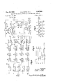
- FIGURE 1 is a combination logic, electrical schematic and block diagram of the control apparatus of the instant invention
- FIG. 2 is a schematic illustration of an exemplary reference signal producing means
- FIG. 3 is a graph showing the time relationships of the various flip-flop outputs of the system logic
- FIG. 4 is a diagrammatic illustration of a paper feed and printing unit of a rotary letterpress.
- FIG. 5 is a fragmentary, diagrammatic perspective view of a pair of plate and blanket cylinders receiving a preprinted web.
- the numeral 10 designates electromechanical reference establishing structure in the form of five cams 12, 14, 16, 18 and 20 rigid with the rotatable line shaft 22 of a rotary letterpress (not shown).
- Line shaft 22 is illustrated diagrammatically, it being apparent that the five cams 1220 will rotate with the line shaft and thus be under the direct control of thepress drive.
- vFive normally open switches 24, 26, 28, 30 and 32 are disposed adjacent respective cams 12-20 for actua-' 3 during each revolution of the line shaft. Direct current is supplied to the switches from the VDC terminals, closing of each switch thereby causing a direct voltage to appear at its associated output lead A, B, C, D or E.
- a pulse sequence comparator is broadly designated 34 and comprises five bistable, multivibrators or flip-flops denoted 1, 2, 3, 4 and 5, and four 2-input AND gates 36, 38, 40 and 42.
- Each of the flip-flops has a set and a reset control input designated S and R respectively, and a pair of outputs designated by the binary numerals and 1 respectively.
- the S inputs of flip-flops 1, 2, 4 and 5 are connected to leads A, B, C and D respectively, the R inputs of all of the flipfiops being connected to the lead E.
- Leads A-E in FIG. 1 correspond to the leads of the same designation in FIG. 2 thereby indicating that the switches 24-32 are connected to the flip-flops as shown and described above.
- a photoelectric scanner 44 is illustrated with its output connected to the S input of flip-flop 3. Scanner 44 is utilized to sense the register marks present on a preprinted web, and will be more fully discussed hereinafter with reference to FIGS. 4 and 5.
- AND gates 36-42 The circuitry of AND gates 36-42 is arranged such that each gate produces command signal at its output when both of its inputs are at the 0 logic level.
- the flip-flops 1-5 are illustrated in their reset states, i.e., the logic levels of their outputs correspond to the reset state and will reverse when the flip-flops are placed in the set state.
- Each of the hold relays 54-60 may, for example, comprise an electromechanical relay having an RC circuit connected across the terminals of its relay coil.
- the relay coil would be momentarily energized by the output pulse from the exciting monostable multivibrator, thereby charging the capacitor of the RC circuit to, in turn, hold the coil in the energized state after termination of the multivibrator pulse for a period determined by the time constant of the RC circuit.
- any other suitable arrangement could be utilized which would, in effect, lengthen the period of the multivibrator pulse.
- Hold relays 54-60 are connected to relay coils 62, '64, 66 and 68 respectively by leads 70, 72, 74 and 76. Energization of a particular hold relay by the preceding multivibrator effects energization of the corresponding relay coil 62, 64, 66 or 68 to shift the associated relay switch from its normal position shown.
- These switches comprise a single-pole, double-throw switch 78 operated by relay coil 62, a normally open switch 80 operated by relay coil 64, a normally closed switch 82 coupled to relay coil 66, and a normally closed relay switch 84 actuated by coil 68.
- the ultimate objective of the system shown in FIGS. 1 and 2 is to control the energization of an alternating current of a torque motor 86 which is operably coupled to means for varying the tension of a preprinted web, which will be discussed hereinafter.
- the motor control circuitry includes a pair of variable autotransformers 88 and 90 having windings 92 and 94 respectively. Alternating current electrical energy is supplied to a pair of power input terminals 9'6 and 98, terminal 96 being connected to the left ends of windings 92 and 94 by lead 100 while terminal 98 is connected to the right ends of coils 92 and 94 by windings 92 and 94 by lead 102.
- the output from autotransformer 88 appears at lead 104 connected to a variable tap 106 of autotransformer 88; similarly, a variable tap 108 of autotransformer 90 supplies output current to a lead 110.
- Leads 104 and 110 are connected to the upper and lower fixed contacts, respectively, of switch 78.
- a lead 112 connected to the left ends of windings 92 and 94 serves as a common output line from the two autotransformers and is connected to a rectifier 114 along with a lead 116.
- Output leads 104 and 110 are selectively connected or disconnected from lead 116 via interconnecting control circuitry including the relay switches 78-84 and a pair of series-connected, variable resistors 118 and 120.
- Switch is connected in shunt relationship to resistor 118, while switch 82 is connected in shunt relationship to resistor 120.
- Switch 84 is connected in series with lead 116 and thus, upon energization of relay coil 68, rectifier 114 is elfectively disconnected from the preceding circuitry.
- the armature of a reversible direct current electric motor is shown at 122 under the control of a forward field winding 124 and a reverse field winding 126.
- Winding 124 is driven by hold relay 54 via lead 70, while winding 1% is driven by hold relay 60 via lead 76.
- the return for the driving circuits of the various hold relays is illustrated by the ground symbol notation.
- Armature 122 is mechanically coupled with the variable tap 108 of autotransformer and, additionally, carries a rotatable cam 128.
- a pair of normally open cam switches and 1132 are disposed for actuation by cam 128 and are angularly disposed with respect to cam 128 so as to correspond to predetermined minimum and maximum settings of variable tap 108.
- Switches 130 and 132 are connected to indicator lamps 134 and 136 respectively, and control energization thereof.
- rectifier 114 is added to the output of a rectifier 138 which is driven by a transducer 140 forming a part of the web tension system.
- the combined outputs of rectifiers 114 and 138 are then connected to the control input of a magnetic amplifier 142 which, in turn, drives a saturable core reactor 144 which energizes the windings of torque motor 86.
- FIG. 3 illustrates the output wave forms appearing at the 0 outputs of flip-flops 1-5 during each operational cycle of the apparatus.
- the 1 logic level of the system corresponds to a negative voltage output from the flipfiops; therefore, the pulses commencing at times t t t t and t represent a change of state of the flip-flops 1-5 from the normal state thereof to the second stable state wherein a l logic level pulse appears at output terminals 0.
- pulses 1, 2, 3, 4 and 5 correspond to flip-flops 1, 2, 3, 4 and 5. Simultaneous resetting of the flip-flops by the closure of switch 32 is illustrated at time t In FIG.
- a printing unit of a rotary letterpress is illustrated diagrammatically.
- a stand 146 supports a rotatable feed roll assembly 148 having a central shaft 150 and three sets of radially extending arms 152 provided with supporting spindles 154 at the ends thereof which carry three rolls of paper 156.
- a web 158 is shown emanating from the outer convolution of the right-hand roll 156, and is trained over a pair of pipe rollers 160, a floating roller 162, and a pair of pipe rollers 164 where the web is then in a position to be scanned by the photoelectric scanner unit 44.
- Web 158 then continues upwardly and is sandwiched between a braked pipe roller 166 and trolleys 168, whereupon web 158 is trainedover another pipe roller 170 and directed between a plate cylinder 172 anda blanket cylinder 174. Web 158 then continues over a pair of pipe rollers 176 and :between a second plate cylinder 178 and blanket cylinder 1'80, and thence over another pipe roller 182 to the folder (not shown) of the printing apparatus. Web tension is maintained by several flexible copper straps 184 yieldably anchored in base 186 by a spring 188.
- Straps 184 are wrapped around a portion of the circumferential periphery of the right-hand roll 156, the upper ends of the straps 184 being secured to respective take-up drums 190 rigid with a shaft 192. (Only one of the drums 190 may be seen in the drawings.)
- Torque motor 86 drives shaft 192 via gear train 194 and a chain and sprocket assembly 196.
- FIG. 5 illustrates that web 158 is preprinted and normally will contain a multicolor pictorial advertising display.
- Regularly spaced register marks 198 are imprinted along one edge of web 158, the distance between adjacent marks 198 defining the repeat length of the preprinted web.
- the web is drawn into the printing apparatus by frictional engagement with the cylinder pairs 172, 174 and 178, 180, these cylinders being operably coupled to the line shaft (illustrated diagrammatically in FIG. 2 at 22) of the press and driven thereby.
- Floating roller 162 is rigidly suspended from a rotatable shaft 200 and is provided with a counterweight 202.
- the housing of transducer 140 is illustrated in FIG. 4 by broken lines, the transducer having a mechanical input coupled with shaft 200.
- Transducer 140 may, for example, comprise a variable transformer device having a shiftable winding driven by shaft 200 in a manner to provide an electrical output from the transducer proportional to the angular displacement of shaft 200 with respect to a predetermined initial angular setting.
- the web is shown in FIG. 4 in a condition of relatively low tension as may be appreciated by the position of floating roller 162.
- floating roller 162 rotates in a counterclockwise direction about the axis of shaft 200 and hence swings upwardly because of the increased pull of the web.
- the floating roller will assume a static position when the pull exerted thereon by the web is exactly offset by counterweight 202 and the inherent weight of the floating roller assembly.
- Transducer 140 monitors the position of floating roller 162 by producing an alternating current electrical signal proportional to the angular displacement of roller 162, as discussed above.
- the transducer output is rectified by rectifier 138 and then combined with the output of rectifier 114, whereupon the composite signal then operates torque motor 86 after amplification and reconversion to alternating current.
- the output of rectifier 114 is controlled by the pressman who sets the rectifier output at a level dependent upon the desired amount of tension to be placed in the web.
- cams 12, 14, 16 and 18 are exaggerated for purposes of clarity. In actual practice, the total angular spacing between the time of closure of switch 24 and the time of closure of switch 30 will likely be only a few degrees.
- the pulse pattern appearing at the 0 outputs of flip-flops 1-5 is as illustrated in FIG. 3.
- the time period between t and L, is the primary control interval.
- Structure 10 is oriented with respect to line shaft 22 such that, for proper registration, the leading edge of pulse 3 from scanner 44 occurs at a time t between the leading edges of pulses 2 and 4. Note that for this particular pulse sequence 2, 3, 4, neither of the AND gates 38 or 40 will deliver a command signal since both of the inputs of each gate are never simultaneously at the 0 logic level.
- multivibrator 48 will continue to pulse hold relay 56 to, in turn, maintain relay coil 64 energized and switch closed.
- This establishes the following circuit: From tap 108 along lead to switch 78, through switches 80 and 82 in shunt with resistors 118 and to switch 84 and thence along lead 116 to rectifier 114.
- resistors 118 or 120 are in the power circuit from tap 108 and that, therefore, full voltage is delivered to rectifier 114.
- switch 80 open rectifier excitation is reduced by the presence of resistance 118.
- the pulse sequence is 3, 1, 2, 4, 5, and both AND gates 36 and 38 will exite respective multivibrators 46 and 48.
- Relay 64 and its associated circuitry will operate as above; relay 62 shifts switch 78 into engagement with its upper contact to establish the following circuit: From tap 106 along lead 104 to switch 78, through switches 80 and 82 to switch 84, and thence along lead 116 to rectifier 114.
- the variable tap 106 of autotransformer 88 is set such that a substantially higher exciting voltage is derived from autotransformer 88 than is obtainable in the normal operational range of autotransformer 90.
- rectifier 114 is suddenly excited with a substantially higher voltage to drive torque motor 86 harder and rapidly increase web tension to correct the misregister.
- hold relay 54 is no longer excited and drops out at the end of its holding time, thereby deenergizing relay coil 62 and reestablishing control in relay coil 64 and its associated circuitry.
- the pulse sequence is 1, 2, 4, 5, 3, and both AND gates 40 and 42 deliver command signals.
- Energization of relay coil 68 opens switch 84 and completely disconnects the input of rectifier 114 from the alternating current supply.
- the tension on straps 184 is completely relaxed and web 158 is free to advance rapidly toward a lead condition since its repeat length is slightly shorter than the repeat length of the secondary operation, as discussed above.
- t hold relay 60 drops out and switch 84 recloses to return system control to relay coil 66 and its associated circuitry.
- Coil 66 will be energized holding switch 82 open to thereby place both of the resistors 118 and 120 in series with lead 116 until the lag condition is corrected.
- cam 128 on the output shaft of armature 122 is oriented to close the appropriate cam switch 130 or 132 to energize the corresponding lamp 134 or 136. This serves as a signal to inform the operating pressman that shutdown of the press must be effected, and the condition corrected either by shaving or underlaying the plates to increase or decrease the repeat length of the overprinting operation.
- the control logic senses the register condition once during each repeat, resulting in immediate detection of a misregister condition during the first repeat that such condition occurs. It should be understood, however, that the degree of misregister present, when the leading edge of output pulse 3 from flip-flop 3 occurs just prior to t or just subsequent to t is not sufficiently severe to cause faulty overprintiug or cutting of the web. With the system of the instant invention, registration within inch of center synchronization is readily maintained.
- Resistors 118 and 118 are adjustable to allow alignment of the apparatus with the particular web tensioning system utilized. The values of these resistors are set depending upon the characteristics of motor 86 and the desired response rate.
- a web fed machine for performing a repetitive secondary operation on a preprinted web provided with regularly spaced register marks, said machine having a drive and means for advancing said web thereinto under tension, apparatus for synchronizing said web with said operation comprising:
- reference establishing means responsive to said drive for producing first and second time spaced reference signals during each repetition of said operation to define a control interval of predetermined duration, said reference establishing means initiating said first and second reference signals at the commencement and the termination of said interval respectively;
- a register mark sensing device adapted for disposition adjacent said web for producing an electrical impulse in response to detection of each of said marks as the web is advanced;
- comparator means coupled with the outputs of said reference establishing means and said device and operable during each repetition of said operation to produce a first command signal in response to initiation of the impulse by said device prior to initiation of said first reference signal, and a second command signal in response to initiation of said second reference signal prior to said impulse initiation;
- a web fed machine for performing a repetitive secondary operation on a preprinted web provided with regularly spaced register marks, said machine having a drive and means for advancing said web thereinto under tension, apparatus for synchronizing said web with said operation comprising:
- reference establishing means responsive to said drive for producing first and second time spaced reference signals during each repetition of said operation to define a control interval of predetermined duration, said reference establishing means initiating said first :and second reference signals at the commencement and the termination of said interval respectively;
- a register mark sensing device adapted for disposition adjacent said web for producing an electrical impulse in response to detection of each of said marks as the web is advanced;
- comparator means coupled with the outputs of said reference establishing means and said device and 9 operable during each repetition of said operation to produce a first command signal when the occurrence of the impulse from said device is prior to the commencement of said interval, and a second command signal when said impulse occurrence is subsequent to the termination of said interval;
- saiu comparator means including first and second AND gates for delivering said first and second command signals respectively, each of said gates having a pair of inputs, and gating control means coupling said inputs with said reference establishing means and said device and normally maintaining one input of each gate at afirst logic level and the other input of each gate at a second logic level;
- said gating control means being operable to excite said one input of the first gate at said second logic level in response to initiation of said first reference signal, to excite said other input of the first gate at said first logic level and said one input of the second gate at said second logic level in response to initiation of said impulse by said device, and to excite said other input of the second gate at said first logic level in response to initiation of said second reference signal;
- each of said gates delivering its command signal when both of its inputs are at the first logic level.
- said gatingcontrol means including three bistable multivibrators
- the first of said multivibrators having a control input for receiving said first reference signal, and an output coupled with said one input of the first gate;
- the second of said multivibrators having a control input for receiving said impulse, and a pair of outputs coupled with said other input of the first gate and said one input of the second gate respectively;
- the third of said multivibrators having a control input for receiving said second reference signal, and an output coupled with said other input of the second gate.
- a web fed machine for performing a repetitive secondary operation on a preprinted web provided with regularly spaced register marks, said machine having a drive and means for advancing said web thereinto under tension, apparatus for synchronizing said web with said operation comprising:
- reference establishing means responsive to said drive for producing first and second time spaced reference signals during each repetition of said operation, said signals defining a control interval of predetermined duration
- a register mark sensing device adapted for disposition adjacent said web for producing an electrical impulse in response to detection of each of said marks as the web is advanced;
- comparator means coupled with the outputs of said reference establishing means and said device and operable during each repetition of said operation to produce a first command signal when the occurrence of the impulse from said device is prior to the commencement of said interval, and a second command signal when said impulse occurrence is subsequent to the termination of said interval;
- said reference establishing means including means for producing third and fourth time spaced reference signals during each repetition of said operation having times of initiation respectively before and after said interval;
- said comparator means including means operable during each repetition of said operation to produce a third command signal when the occurrence of the impulse from said device is prior to said initiation of said third reference signal, and a fourth command signal when said impulse occurrence is subsequent to the initiation of said fourth reference signal;
- said tension increasing and decreasing means including first circuit means responsive to said first and second command signals for varying the web tension at a relatively slow rate, and second circuit means for increasing and decreasing the web tension at a relatively fast rate in response to said third and fourth command signals, respectively.
- said tension increasing and decreasing means further including means intercoupling said first and second circuit means and responsive to said third command signal for automatically increasing the amount of web tension increase effected by said first circuit means, and responsive to said fourth command signal for automatically decreasing the amount of said tension increase effected by said first circuit means.
- said automatic means comprising a variable impedance component operably interposed in said first circuit means, and electrically responsive structure coupled with said component for varying the impedance thereof.
Description
Aug. 20, 1968 BETTS ETAL 3,397,634
REGISTRATION CONTROL SYSTEM FOR PREPRINTED WEB INSERTION Filed Sept. 13, 1965 2 Sheets-Sheet 1 INVENTORS. Minfor'd E. Beffs Richard L. Haifa/7 ATTOR s.
REGISTRATION CONTROL SYSTEM FOR PREPRINTED WEB INSERTION Filed Sept. 13, 1965 2 Sheets-Sheet 2 INVENTORS. Minf'oi'd E. Beffs Richard L. Haffon United States Patent 3,397,634 REGISTRATION CONTROL SYSTEM FOR PREPRINTED WEB INSERTION Minford E. Betts, Odessa, Mo., and Richard L. Hatton, Fairway, Kans., assignors to The Kansas City Star Company, Kansas City, Mo., a corporation of Missouri Filed Sept. 13, 1965, Ser. No. 486,726
6 Claims. (Cl. 101-248) ABSTRACT OF THE DISCLOSURE A preprinted web insetter for a rotary letterpress derives a pair of time spaced reference signals from the line shaft of the press during each revolution of such shaft. The register marks on the preprinted web are sensed as each mark passes a photoelectric scanner. The two reference signals define a primary control interval for assuring proper registration of the Web with the printing operation. If the output from the scanner occurs prior to initiation of the first reference signal, then the tension. of the web is increased; conversely, the web tension is decreased if the second reference signal is initiated prior to sensing of the mark by the scanner. In this manner, lead and lag conditions are compensated to assure proper registration, a condition existing when the scanner output occurs during the control interval. Additionally, in instances where the degree of misregistration is quite severe, a highly responsive corrective action is taken by the provision of supplemental control intervals bounding the beginning and the end of the primary control interval.
This invention relates to a preprinted web insetter for rotary letterpresses and, more specifically, to an insetter operable in conjunction with a letterpress web tension system to assure registration of the web with a secondary operation performed by the press.
A recent advertising technique developed in the newspaper industry utilizes preprinted rolls of paper containing multicolor advertising matter which are fed into the newspaper press for ultimate cutting, folding and interleaving with the other pages of the newspaper. This facilitates mass media advertising on a territorial or nationwide basis from a single source, and provides pictorial advertising copy of high quality.
Special problems are encountered in the insertion of a preprinted web into a rotary letterpress since a certain phase discrepancy will exist between the preprinted image and secondary operations to be performed by the press. Such operations may include overprinting to identify the local advertiser, and will include the necessary tucking, cutting and folding of the web which enables each repeat length to be interleaved with the other pages of the newspaper.
In order to provide a means of controlling registration of the preprinted Web with the secondary operation, the web is printed with register marks spaced at regular intervals along one edge thereof to define the boundary between each recurring image. The repeat length (distance between register marks) is purposely slightly shorter than the repeat length of the letterpress so that the tendency of the preprinted web, when the same is not under tension, is to gain or assume a leading position with respect to proper synchronization with the secondary operations performed by the press. Thus, stretching of the web by operation of the web tensioning system of the press will effect synchronization of the web and the secondary operations if the repeat lengths of the press and the web are compatible.
Insetting equipment developed heretofore for use with preprinted webs has endeavored to control the press web 3,397,634 Patented Aug. 20, 1968 "ice tensioning system in a manner to assure substantial registration; however, such equipment has been relatively complex and available only at high cost. Manifestly, this greatly limits the popularity and coverage of this advertising technique since only the larger metropolitan newspapers have sufficient capital to install the required insetting equipment.
It is, therefore, the primary object of this invention to provide a preprinted web insetter of high reliability and substantially reduced complexity, but which is capable of maintaining a high degree of registration.
As a corollary to the foregoing object, it is an important aim of the instant invention to provide a preprinted web insetter which may be readily attached to rotary newspaper letterpresses of various types and which, additionally, may be utilized in association with any of the various printing units of a multiunit letterpress.
A further and important object of the invention is to provide an insetter as aforesaid which may be readily coupled with an existing web tension system of a selected printing unit of a multiunit letterpress and, if desired, shifted to another printing uint of the press in a minimum time and with a minimum of inconvenience.
Another object of the invention is to provide an insetter for a preprinted web which eletcrically establishes a control interval, during each repetition of the secondary operation, that is utilized as a reference and compared with an electrical impulse produced in response to the register marks carried by the web to, in turn, produce a command signal if the occurrence of the impulse is either prior to or subsequent to the reference interval. The command signal is then employed to operate the web tension system in a manner to increase or decrease the tension as required to reestablish synchronization of the web with the secondary operation.
Still another object of the instant invention is to provide control means for operating the web tension system at either a high or a low response rate depending upon the magnitude of the misregistration.
In the drawings:
FIGURE 1 is a combination logic, electrical schematic and block diagram of the control apparatus of the instant invention;
FIG. 2 is a schematic illustration of an exemplary reference signal producing means;
FIG. 3 is a graph showing the time relationships of the various flip-flop outputs of the system logic;
FIG. 4 is a diagrammatic illustration of a paper feed and printing unit of a rotary letterpress; and
FIG. 5 is a fragmentary, diagrammatic perspective view of a pair of plate and blanket cylinders receiving a preprinted web.
. Referring initially to FIG. 2, the numeral 10 designates electromechanical reference establishing structure in the form of five cams 12, 14, 16, 18 and 20 rigid with the rotatable line shaft 22 of a rotary letterpress (not shown). Line shaft 22 is illustrated diagrammatically, it being apparent that the five cams 1220 will rotate with the line shaft and thus be under the direct control of thepress drive.
vFive normally open switches 24, 26, 28, 30 and 32 are disposed adjacent respective cams 12-20 for actua-' 3 during each revolution of the line shaft. Direct current is supplied to the switches from the VDC terminals, closing of each switch thereby causing a direct voltage to appear at its associated output lead A, B, C, D or E.
In FIG. 1 a pulse sequence comparator is broadly designated 34 and comprises five bistable, multivibrators or flip-flops denoted 1, 2, 3, 4 and 5, and four 2-input AND gates 36, 38, 40 and 42. Each of the flip-flops has a set and a reset control input designated S and R respectively, and a pair of outputs designated by the binary numerals and 1 respectively. The S inputs of flip- flops 1, 2, 4 and 5 are connected to leads A, B, C and D respectively, the R inputs of all of the flipfiops being connected to the lead E. Leads A-E in FIG. 1 correspond to the leads of the same designation in FIG. 2 thereby indicating that the switches 24-32 are connected to the flip-flops as shown and described above.
A photoelectric scanner 44 is illustrated with its output connected to the S input of flip-flop 3. Scanner 44 is utilized to sense the register marks present on a preprinted web, and will be more fully discussed hereinafter with reference to FIGS. 4 and 5.
The circuitry of AND gates 36-42 is arranged such that each gate produces command signal at its output when both of its inputs are at the 0 logic level. The flip-flops 1-5 are illustrated in their reset states, i.e., the logic levels of their outputs correspond to the reset state and will reverse when the flip-flops are placed in the set state. Thus, it will be appreciated that, under the normal conditions shown, none of the AND gates 36-42 are delivering a command signal since the two input terminals of each gate are at a different logic level.
The outputs of AND gates 36-42 are coupled with the inputs of respective monostable multivibrators 46, 48, 50 and 52 which, in turn, drive hold relays 54, 56, 58 and 60 respectively. Each of the hold relays 54-60 may, for example, comprise an electromechanical relay having an RC circuit connected across the terminals of its relay coil. In such an arrangement, the relay coil would be momentarily energized by the output pulse from the exciting monostable multivibrator, thereby charging the capacitor of the RC circuit to, in turn, hold the coil in the energized state after termination of the multivibrator pulse for a period determined by the time constant of the RC circuit. Alternatively, any other suitable arrangement could be utilized which would, in effect, lengthen the period of the multivibrator pulse.
Hold relays 54-60 are connected to relay coils 62, '64, 66 and 68 respectively by leads 70, 72, 74 and 76. Energization of a particular hold relay by the preceding multivibrator effects energization of the corresponding relay coil 62, 64, 66 or 68 to shift the associated relay switch from its normal position shown. These switches comprise a single-pole, double-throw switch 78 operated by relay coil 62, a normally open switch 80 operated by relay coil 64, a normally closed switch 82 coupled to relay coil 66, and a normally closed relay switch 84 actuated by coil 68.
The ultimate objective of the system shown in FIGS. 1 and 2 is to control the energization of an alternating current of a torque motor 86 which is operably coupled to means for varying the tension of a preprinted web, which will be discussed hereinafter. The motor control circuitry includes a pair of variable autotransformers 88 and 90 having windings 92 and 94 respectively. Alternating current electrical energy is supplied to a pair of power input terminals 9'6 and 98, terminal 96 being connected to the left ends of windings 92 and 94 by lead 100 while terminal 98 is connected to the right ends of coils 92 and 94 by windings 92 and 94 by lead 102. The output from autotransformer 88 appears at lead 104 connected to a variable tap 106 of autotransformer 88; similarly, a variable tap 108 of autotransformer 90 supplies output current to a lead 110. Leads 104 and 110 are connected to the upper and lower fixed contacts, respectively, of switch 78. A lead 112 connected to the left ends of windings 92 and 94 serves as a common output line from the two autotransformers and is connected to a rectifier 114 along with a lead 116.
Output leads 104 and 110 are selectively connected or disconnected from lead 116 via interconnecting control circuitry including the relay switches 78-84 and a pair of series-connected, variable resistors 118 and 120. Switch is connected in shunt relationship to resistor 118, while switch 82 is connected in shunt relationship to resistor 120. Switch 84 is connected in series with lead 116 and thus, upon energization of relay coil 68, rectifier 114 is elfectively disconnected from the preceding circuitry.
The armature of a reversible direct current electric motor is shown at 122 under the control of a forward field winding 124 and a reverse field winding 126. Winding 124 is driven by hold relay 54 via lead 70, while winding 1% is driven by hold relay 60 via lead 76. The return for the driving circuits of the various hold relays is illustrated by the ground symbol notation.
The output of rectifier 114 is added to the output of a rectifier 138 which is driven by a transducer 140 forming a part of the web tension system. The combined outputs of rectifiers 114 and 138 are then connected to the control input of a magnetic amplifier 142 which, in turn, drives a saturable core reactor 144 which energizes the windings of torque motor 86.
FIG. 3 illustrates the output wave forms appearing at the 0 outputs of flip-flops 1-5 during each operational cycle of the apparatus. The 1 logic level of the system corresponds to a negative voltage output from the flipfiops; therefore, the pulses commencing at times t t t t and t represent a change of state of the flip-flops 1-5 from the normal state thereof to the second stable state wherein a l logic level pulse appears at output terminals 0. Like designations are utilized for each flip-flop and its associated 0 output terminal wave form, i.e., pulses 1, 2, 3, 4 and 5 correspond to flip- flops 1, 2, 3, 4 and 5. Simultaneous resetting of the flip-flops by the closure of switch 32 is illustrated at time t In FIG. 4 a printing unit of a rotary letterpress is illustrated diagrammatically. A stand 146 supports a rotatable feed roll assembly 148 having a central shaft 150 and three sets of radially extending arms 152 provided with supporting spindles 154 at the ends thereof which carry three rolls of paper 156. A web 158 is shown emanating from the outer convolution of the right-hand roll 156, and is trained over a pair of pipe rollers 160, a floating roller 162, and a pair of pipe rollers 164 where the web is then in a position to be scanned by the photoelectric scanner unit 44.
The web then continues upwardly and is sandwiched between a braked pipe roller 166 and trolleys 168, whereupon web 158 is trainedover another pipe roller 170 and directed between a plate cylinder 172 anda blanket cylinder 174. Web 158 then continues over a pair of pipe rollers 176 and :between a second plate cylinder 178 and blanket cylinder 1'80, and thence over another pipe roller 182 to the folder (not shown) of the printing apparatus. Web tension is maintained by several flexible copper straps 184 yieldably anchored in base 186 by a spring 188. (Only one of the straps 184 is visible in the drawing.) Straps 184 are wrapped around a portion of the circumferential periphery of the right-hand roll 156, the upper ends of the straps 184 being secured to respective take-up drums 190 rigid with a shaft 192. (Only one of the drums 190 may be seen in the drawings.) Torque motor 86 drives shaft 192 via gear train 194 and a chain and sprocket assembly 196.
FIG. 5 illustrates that web 158 is preprinted and normally will contain a multicolor pictorial advertising display. Regularly spaced register marks 198 are imprinted along one edge of web 158, the distance between adjacent marks 198 defining the repeat length of the preprinted web. The web is drawn into the printing apparatus by frictional engagement with the cylinder pairs 172, 174 and 178, 180, these cylinders being operably coupled to the line shaft (illustrated diagrammatically in FIG. 2 at 22) of the press and driven thereby.
Floating roller 162 is rigidly suspended from a rotatable shaft 200 and is provided with a counterweight 202. The housing of transducer 140 is illustrated in FIG. 4 by broken lines, the transducer having a mechanical input coupled with shaft 200. Transducer 140 may, for example, comprise a variable transformer device having a shiftable winding driven by shaft 200 in a manner to provide an electrical output from the transducer proportional to the angular displacement of shaft 200 with respect to a predetermined initial angular setting.
Operation In operation, it will be assumed that it is desired to register web 158 with copy to be o-verprin-ted thereon by plate cylinders 172 and 178. It will be appreciated that the two plate cylinders overprint opposed sides of web 158, whereupon the web then travels to the folder mechanism of the press where it is tucked, severed, and then folded to form pages of a newspaper interleaved with the regular pages thereof containing the usual black copy and black and white photographs imprinted by the other printing units of the letterpress.
If pressure on straps 184 is released by de-energization of torque motor 86, the tension on web 158 will be relaxed and the web will tend to lead plate cylinders 172 and 178 due to the fact that the repeat length of the web is purposely made slightly shorter than the repeat length of the plate cylinders. As torque motor 86 is excited, shaft 192 rotates in a clockwise direction to wind straps 184 about drums 190 and thus increase the web tension. This effects stretching of the web and actually increases the repeat length thereof so that, ultimately, registration with the plate cylinders may be obtained. It is assumed, however, that the repeat lengths of-the web and the plate cylinders are compatible, i.e., the repeat length of the web is sufficiently long to permit an in-register condition to be attained within the elastic limit of the web.
The web is shown in FIG. 4 in a condition of relatively low tension as may be appreciated by the position of floating roller 162. As web tension is increased, floating roller 162 rotates in a counterclockwise direction about the axis of shaft 200 and hence swings upwardly because of the increased pull of the web. The floating roller will assume a static position when the pull exerted thereon by the web is exactly offset by counterweight 202 and the inherent weight of the floating roller assembly.
It will be appreciated from the foregoing that connection of the instant invention with a particular printing unit tension system of a letterpress requires only that structure 10 and scanner 44 be installed on the unit, together with substitution of the control circuitry of FIG. 1 for the manual pressmans control. Line shaft 22 completes one revolution during each cycle or repetition of the secondary operation performed on the preprinted web 158- by the press. The secondary operation illustrated in FIG. 4 is the overprinting of both sides of web 158 by plate cylinders 172 and 178. Those skilled in the printing art will appreciate that, in presses in which the plate cylinders 172 and 178 each carry two pages around, the printing operation \cycle corresponding to one revolution of line shaft 22 will be the printing of one page or one-half revolution of cylinders 172 and 178. In some instances overprinting will not be desired; however, in any event, repetitive secondary operations must be performed by the folder in order to interleave the preprinted sheets with the other pages of the newspaper.
The spacing of cams 12, 14, 16 and 18 is exaggerated for purposes of clarity. In actual practice, the total angular spacing between the time of closure of switch 24 and the time of closure of switch 30 will likely be only a few degrees.
Assuming that web 158 is properly registered with the plate cylinders, the pulse pattern appearing at the 0 outputs of flip-flops 1-5 is as illustrated in FIG. 3. The time period between t and L, is the primary control interval. Structure 10 is oriented with respect to line shaft 22 such that, for proper registration, the leading edge of pulse 3 from scanner 44 occurs at a time t between the leading edges of pulses 2 and 4. Note that for this particular pulse sequence 2, 3, 4, neither of the AND gates 38 or 40 will deliver a command signal since both of the inputs of each gate are never simultaneously at the 0 logic level.
In the event that web 158 should begin to lead cylinders 172 and 178, register marks 198 will pass scanner 44 ahead of proper synchronization, resulting in the occurrence of the leading edge of pulse 3 at a time earlier than t Thus, the sequence of the three pulses presently under consideration will be 3, 2, 4, and AND gate 38 will now deliver a command signal to monostable multivibrator 48 since both of its inputs will be momentarily excited at the 0 logic level. (It will be appreciated that the pulse output from the 1 output of each flip-flop is identical to the pulse appearing at the 0 output thereof, when the S input terminal is excited, except that it assumes the 0 logic level.)
As long as the lead condition exists, multivibrator 48 will continue to pulse hold relay 56 to, in turn, maintain relay coil 64 energized and switch closed. This establishes the following circuit: From tap 108 along lead to switch 78, through switches 80 and 82 in shunt with resistors 118 and to switch 84 and thence along lead 116 to rectifier 114. Thus, it will be appreciated that neither of the resistors 118 or 120 are in the power circuit from tap 108 and that, therefore, full voltage is delivered to rectifier 114. Normally, with switch 80 open, rectifier excitation is reduced by the presence of resistance 118.
Conversely, if a lag condition occurs, the sequence of the three pulses under consideration is 2, 4, 3, and AND gate 40 delivers a command signal to multivibrator 50. As long as the lag condition persists, multivibrator will continue to pulse hold relay 58 and relay coil 66 will be maintained energized with switch 82 held open. This places both resistors 118 and 120 in series with lead 116 to reduce excitation to rectifier 114 and, therefore, reduce the drive to motor 86 to decrease web tension.
The previous discussion has dealt entirely with the control zone between the times t and t In certain instances, the degree of misregistration will be quite severe, necessitating that a highly responsive corrective action be taken in order to correct the misregister condition. For this purpose, supplemental control intervals i 4 and t -t are provided.
Assuming a condition of extreme lead misregister, the pulse sequence is 3, 1, 2, 4, 5, and both AND gates 36 and 38 will exite respective multivibrators 46 and 48. Relay 64 and its associated circuitry will operate as above; relay 62 shifts switch 78 into engagement with its upper contact to establish the following circuit: From tap 106 along lead 104 to switch 78, through switches 80 and 82 to switch 84, and thence along lead 116 to rectifier 114. The variable tap 106 of autotransformer 88 is set such that a substantially higher exciting voltage is derived from autotransformer 88 than is obtainable in the normal operational range of autotransformer 90. Thus, rectifier 114 is suddenly excited with a substantially higher voltage to drive torque motor 86 harder and rapidly increase web tension to correct the misregister. As the condition improves and the leading edge of pulse 3 falls between pulses 1 and 2, hold relay 54 is no longer excited and drops out at the end of its holding time, thereby deenergizing relay coil 62 and reestablishing control in relay coil 64 and its associated circuitry.
During severe lead conditions when hold relay 54 is in operation, forward winding 124 is also excited to effect rotation of armature 122 of the reversible DC motor. Armature 122 drives variable tap 108 in a clockwise direction as viewed in FIG. 1 to increase the voltage output of autotransformer 90. Thus, when hold relay 54 drops out and control is transferred to autotransformer 90, this transformer will now excite rectifier 114 with an increased voltage.
In instances of severe lag error, the pulse sequence is 1, 2, 4, 5, 3, and both AND gates 40 and 42 deliver command signals. Energization of relay coil 68 opens switch 84 and completely disconnects the input of rectifier 114 from the alternating current supply. Thus, the tension on straps 184 is completely relaxed and web 158 is free to advance rapidly toward a lead condition since its repeat length is slightly shorter than the repeat length of the secondary operation, as discussed above. Once the leading edge of pulse 3 is initiated between the times t; and t hold relay 60 drops out and switch 84 recloses to return system control to relay coil 66 and its associated circuitry. Coil 66 will be energized holding switch 82 open to thereby place both of the resistors 118 and 120 in series with lead 116 until the lag condition is corrected.
As in the case of the extreme lead misregister, opera: tion of hold relay 60 by extreme lag misregister effects rotation of armature 122 of the DC motor coupled with variable tap 108. The reverse winding 126 is energized by lead 76 to shift tap 108 in the counterclockwise direction so that, when power is reestablished to rectifier 114, the output of autotransformer 90 will be at a lower level.
In those instances where correction of misregister is impossible because web 158 has too long or too short a repeat length, cam 128 on the output shaft of armature 122 is oriented to close the appropriate cam switch 130 or 132 to energize the corresponding lamp 134 or 136. This serves as a signal to inform the operating pressman that shutdown of the press must be effected, and the condition corrected either by shaving or underlaying the plates to increase or decrease the repeat length of the overprinting operation.
Due to the action of cam 20 and its associated switch 32, all of the flip-flops are reset at a time t during each revolution of line shaft 22 or each repeat of the secondary operation. Thus, the control logic senses the register condition once during each repeat, resulting in immediate detection of a misregister condition during the first repeat that such condition occurs. It should be understood, however, that the degree of misregister present, when the leading edge of output pulse 3 from flip-flop 3 occurs just prior to t or just subsequent to t is not sufficiently severe to cause faulty overprintiug or cutting of the web. With the system of the instant invention, registration within inch of center synchronization is readily maintained.
Having thus described the invention, what is claimed as new and desired to be secured by Letters Patent is:
1. In a web fed machine for performing a repetitive secondary operation on a preprinted web provided with regularly spaced register marks, said machine having a drive and means for advancing said web thereinto under tension, apparatus for synchronizing said web with said operation comprising:
reference establishing means responsive to said drive for producing first and second time spaced reference signals during each repetition of said operation to define a control interval of predetermined duration, said reference establishing means initiating said first and second reference signals at the commencement and the termination of said interval respectively;
a register mark sensing device adapted for disposition adjacent said web for producing an electrical impulse in response to detection of each of said marks as the web is advanced;
comparator means coupled with the outputs of said reference establishing means and said device and operable during each repetition of said operation to produce a first command signal in response to initiation of the impulse by said device prior to initiation of said first reference signal, and a second command signal in response to initiation of said second reference signal prior to said impulse initiation; and
means coupled with said comparator means for increasing the tension of said web in response to said first command signal, and for decreasing the web tension in response to said second command signal, whereby to compensate for lead and lag conditions.
2. In a web fed machine for performing a repetitive secondary operation on a preprinted web provided with regularly spaced register marks, said machine having a drive and means for advancing said web thereinto under tension, apparatus for synchronizing said web with said operation comprising:
reference establishing means responsive to said drive for producing first and second time spaced reference signals during each repetition of said operation to define a control interval of predetermined duration, said reference establishing means initiating said first :and second reference signals at the commencement and the termination of said interval respectively;
a register mark sensing device adapted for disposition adjacent said web for producing an electrical impulse in response to detection of each of said marks as the web is advanced;
comparator means coupled with the outputs of said reference establishing means and said device and 9 operable during each repetition of said operation to produce a first command signal when the occurrence of the impulse from said device is prior to the commencement of said interval, and a second command signal when said impulse occurrence is subsequent to the termination of said interval; and
means coupled with said comparator means for increasing the tension of said web in response to said first command signal, and for decreasing the web tension in response to said second command signal, whereby to compensate for lead and lag conditions;
saiu comparator means including first and second AND gates for delivering said first and second command signals respectively, each of said gates having a pair of inputs, and gating control means coupling said inputs with said reference establishing means and said device and normally maintaining one input of each gate at afirst logic level and the other input of each gate at a second logic level;
said gating control means being operable to excite said one input of the first gate at said second logic level in response to initiation of said first reference signal, to excite said other input of the first gate at said first logic level and said one input of the second gate at said second logic level in response to initiation of said impulse by said device, and to excite said other input of the second gate at said first logic level in response to initiation of said second reference signal;
each of said gates delivering its command signal when both of its inputs are at the first logic level.
3. The invention of claim 2:
said gatingcontrol means including three bistable multivibrators;
the first of said multivibrators having a control input for receiving said first reference signal, and an output coupled with said one input of the first gate;
the second of said multivibrators having a control input for receiving said impulse, and a pair of outputs coupled with said other input of the first gate and said one input of the second gate respectively;
the third of said multivibrators having a control input for receiving said second reference signal, and an output coupled with said other input of the second gate.
4. In a web fed machine for performing a repetitive secondary operation on a preprinted web provided with regularly spaced register marks, said machine having a drive and means for advancing said web thereinto under tension, apparatus for synchronizing said web with said operation comprising:
reference establishing means responsive to said drive for producing first and second time spaced reference signals during each repetition of said operation, said signals defining a control interval of predetermined duration;
a register mark sensing device adapted for disposition adjacent said web for producing an electrical impulse in response to detection of each of said marks as the web is advanced;
comparator means coupled with the outputs of said reference establishing means and said device and operable during each repetition of said operation to produce a first command signal when the occurrence of the impulse from said device is prior to the commencement of said interval, and a second command signal when said impulse occurrence is subsequent to the termination of said interval; and
:means coupled with said comparator means for increasing the tension of said web in response to said first command signal, and for decreasing the web tension in response to said second command signal, whereby to compensate for lead and lag conditions;
said reference establishing means including means for producing third and fourth time spaced reference signals during each repetition of said operation having times of initiation respectively before and after said interval;
said comparator means including means operable during each repetition of said operation to produce a third command signal when the occurrence of the impulse from said device is prior to said initiation of said third reference signal, and a fourth command signal when said impulse occurrence is subsequent to the initiation of said fourth reference signal;
said tension increasing and decreasing means including first circuit means responsive to said first and second command signals for varying the web tension at a relatively slow rate, and second circuit means for increasing and decreasing the web tension at a relatively fast rate in response to said third and fourth command signals, respectively.
5. The invention of claim 4:
said tension increasing and decreasing means further including means intercoupling said first and second circuit means and responsive to said third command signal for automatically increasing the amount of web tension increase effected by said first circuit means, and responsive to said fourth command signal for automatically decreasing the amount of said tension increase effected by said first circuit means.
6. The invention of claim 5:
said automatic means comprising a variable impedance component operably interposed in said first circuit means, and electrically responsive structure coupled with said component for varying the impedance thereof.
References Cited UNITED STATES PATENTS 2,522,479 9/1950 Crafts 22628 XR 2,549,605 4/1951 Huck l01l81 2,873,117 2/1959 Crosfield et al. 22628 3,276,647 10/1966 Lewis et al. 22631 3,264,983 8/1966 Lewis et al. l01248 XR ROBERT E. PULFREY, Primary Examiner.
J. R. FISHER, Assistant Examiner.
Priority Applications (1)
| Application Number | Priority Date | Filing Date | Title |
|---|---|---|---|
| US486726A US3397634A (en) | 1965-09-13 | 1965-09-13 | Registration control system for preprinted web insertion |
Applications Claiming Priority (1)
| Application Number | Priority Date | Filing Date | Title |
|---|---|---|---|
| US486726A US3397634A (en) | 1965-09-13 | 1965-09-13 | Registration control system for preprinted web insertion |
Publications (1)
| Publication Number | Publication Date |
|---|---|
| US3397634A true US3397634A (en) | 1968-08-20 |
Family
ID=23933019
Family Applications (1)
| Application Number | Title | Priority Date | Filing Date |
|---|---|---|---|
| US486726A Expired - Lifetime US3397634A (en) | 1965-09-13 | 1965-09-13 | Registration control system for preprinted web insertion |
Country Status (1)
| Country | Link |
|---|---|
| US (1) | US3397634A (en) |
Cited By (8)
| Publication number | Priority date | Publication date | Assignee | Title |
|---|---|---|---|---|
| US3774016A (en) * | 1971-10-04 | 1973-11-20 | Sun Chemical Corp | Control of process according to registration indicia on material being processed |
| US3841216A (en) * | 1972-12-07 | 1974-10-15 | Hamilton Tool Co | Method of and apparatus for correcting deviations in length and registration in a continuous strip of material |
| DE2711744A1 (en) * | 1977-03-17 | 1978-09-21 | Windmoeller & Hoelscher | METHOD AND DEVICE FOR REGULATING THE SUBSTANTIAL AND PHASE-CORRECT PRINTING OF PRE-PRINTED WEBS IN PRINTING MACHINES |
| US4264957A (en) * | 1979-05-23 | 1981-04-28 | Zerand Corporation | Apparatus and method for register control in web processing apparatus |
| US4366372A (en) * | 1979-06-01 | 1982-12-28 | Innovative Design, Inc. | Apparatus and method for counting repetitive marks on a running web |
| US4401024A (en) * | 1982-04-07 | 1983-08-30 | Milliken Research Corporation | Electronic patterning with registration control |
| WO1988003119A1 (en) * | 1986-10-27 | 1988-05-05 | Adolph Coors Company | Phasing control system for web having variable repeat length portions |
| US4757930A (en) * | 1986-08-29 | 1988-07-19 | Adolph Coors Company | Web indicia reference signal generating system |
Citations (5)
| Publication number | Priority date | Publication date | Assignee | Title |
|---|---|---|---|---|
| US2522479A (en) * | 1946-09-27 | 1950-09-12 | Goss Printing Press Co Ltd | Registration control device |
| US2549605A (en) * | 1945-04-16 | 1951-04-17 | Hoe & Co R | Register control device for web printing machines |
| US2873117A (en) * | 1955-04-01 | 1959-02-10 | Crosfield J F Ltd | Register control of moving webs |
| US3264983A (en) * | 1964-02-18 | 1966-08-09 | Champlain Company Inc | Registration system for a moving web |
| US3276647A (en) * | 1964-03-31 | 1966-10-04 | Champlain Company Inc | Register control system for a moving web |
-
1965
- 1965-09-13 US US486726A patent/US3397634A/en not_active Expired - Lifetime
Patent Citations (5)
| Publication number | Priority date | Publication date | Assignee | Title |
|---|---|---|---|---|
| US2549605A (en) * | 1945-04-16 | 1951-04-17 | Hoe & Co R | Register control device for web printing machines |
| US2522479A (en) * | 1946-09-27 | 1950-09-12 | Goss Printing Press Co Ltd | Registration control device |
| US2873117A (en) * | 1955-04-01 | 1959-02-10 | Crosfield J F Ltd | Register control of moving webs |
| US3264983A (en) * | 1964-02-18 | 1966-08-09 | Champlain Company Inc | Registration system for a moving web |
| US3276647A (en) * | 1964-03-31 | 1966-10-04 | Champlain Company Inc | Register control system for a moving web |
Cited By (9)
| Publication number | Priority date | Publication date | Assignee | Title |
|---|---|---|---|---|
| US3774016A (en) * | 1971-10-04 | 1973-11-20 | Sun Chemical Corp | Control of process according to registration indicia on material being processed |
| US3841216A (en) * | 1972-12-07 | 1974-10-15 | Hamilton Tool Co | Method of and apparatus for correcting deviations in length and registration in a continuous strip of material |
| DE2711744A1 (en) * | 1977-03-17 | 1978-09-21 | Windmoeller & Hoelscher | METHOD AND DEVICE FOR REGULATING THE SUBSTANTIAL AND PHASE-CORRECT PRINTING OF PRE-PRINTED WEBS IN PRINTING MACHINES |
| US4264957A (en) * | 1979-05-23 | 1981-04-28 | Zerand Corporation | Apparatus and method for register control in web processing apparatus |
| US4366372A (en) * | 1979-06-01 | 1982-12-28 | Innovative Design, Inc. | Apparatus and method for counting repetitive marks on a running web |
| US4401024A (en) * | 1982-04-07 | 1983-08-30 | Milliken Research Corporation | Electronic patterning with registration control |
| US4757930A (en) * | 1986-08-29 | 1988-07-19 | Adolph Coors Company | Web indicia reference signal generating system |
| US4781317A (en) * | 1986-08-29 | 1988-11-01 | Adolph Coors Company | Phasing control system for web having variable repeat length portions |
| WO1988003119A1 (en) * | 1986-10-27 | 1988-05-05 | Adolph Coors Company | Phasing control system for web having variable repeat length portions |
Similar Documents
| Publication | Publication Date | Title |
|---|---|---|
| US3557692A (en) | Plural independently operable motor drive arrangement in printing press | |
| JP3002167B2 (en) | Drive for printing press | |
| US3561654A (en) | Device for maintaining constant the tension of a web pulled through printing units of a printing press | |
| US3397634A (en) | Registration control system for preprinted web insertion | |
| US4658723A (en) | Color printing machine | |
| US2105185A (en) | Web registering mechanism | |
| GB2151188A (en) | Printing apparatus | |
| US3084621A (en) | Process and apparatus for controlling register on rotogravure printing machines | |
| US2522479A (en) | Registration control device | |
| US3073997A (en) | Multi-unit sheet-fed printing machine | |
| US3335928A (en) | Control of web elongation | |
| US3191530A (en) | Detector system for plural unit printing press | |
| US3595567A (en) | Sheet detection control for sheet-handling apparatus,particulary a printing press | |
| US1970368A (en) | Printing press | |
| JP2508829B2 (en) | Registration method in web printing | |
| US3196787A (en) | Inking drive and interrupter for multicolor aniline printing machine | |
| US1993579A (en) | Synchronizing system for unit-type printing presses | |
| US2518325A (en) | Electronic synchronizing device and magnetic switch | |
| JPH09314813A (en) | Printing unit for changing-over type continuous operation | |
| US2518324A (en) | Electronic synchronizing circuit | |
| US3027462A (en) | Apparatus for bringing two moving indicia marks into register with each other | |
| US1831156A (en) | Printing machine | |
| US2536679A (en) | Registering mechanism for rotary offset printing machines | |
| EP0053729B1 (en) | Apparatus for controlling the timings of sequentially throwing on or off cylinders of printing press | |
| US2135028A (en) | Recording device |