US3388922A - Safety ski binding - Google Patents
Safety ski binding Download PDFInfo
- Publication number
- US3388922A US3388922A US528647A US52864766A US3388922A US 3388922 A US3388922 A US 3388922A US 528647 A US528647 A US 528647A US 52864766 A US52864766 A US 52864766A US 3388922 A US3388922 A US 3388922A
- Authority
- US
- United States
- Prior art keywords
- ski binding
- safety ski
- clamping jaw
- safety
- swivelling arm
- Prior art date
- Legal status (The legal status is an assumption and is not a legal conclusion. Google has not performed a legal analysis and makes no representation as to the accuracy of the status listed.)
- Expired - Lifetime
Links
- 230000027455 binding Effects 0.000 title description 30
- 238000009739 binding Methods 0.000 title description 30
- 230000033001 locomotion Effects 0.000 description 4
- 238000010276 construction Methods 0.000 description 3
- 208000010392 Bone Fractures Diseases 0.000 description 1
- 238000004049 embossing Methods 0.000 description 1
- 230000002349 favourable effect Effects 0.000 description 1
- PSGAAPLEWMOORI-PEINSRQWSA-N medroxyprogesterone acetate Chemical compound C([C@@]12C)CC(=O)C=C1[C@@H](C)C[C@@H]1[C@@H]2CC[C@]2(C)[C@@](OC(C)=O)(C(C)=O)CC[C@H]21 PSGAAPLEWMOORI-PEINSRQWSA-N 0.000 description 1
- 230000000452 restraining effect Effects 0.000 description 1
- 230000035945 sensitivity Effects 0.000 description 1
Images
Classifications
-
- A—HUMAN NECESSITIES
- A63—SPORTS; GAMES; AMUSEMENTS
- A63C—SKATES; SKIS; ROLLER SKATES; DESIGN OR LAYOUT OF COURTS, RINKS OR THE LIKE
- A63C9/00—Ski bindings
- A63C9/08—Ski bindings yieldable or self-releasing in the event of an accident, i.e. safety bindings
- A63C9/085—Ski bindings yieldable or self-releasing in the event of an accident, i.e. safety bindings with sole hold-downs, e.g. swingable
- A63C9/08557—Details of the release mechanism
- A63C9/08564—Details of the release mechanism using cam or slide surface
-
- A—HUMAN NECESSITIES
- A63—SPORTS; GAMES; AMUSEMENTS
- A63C—SKATES; SKIS; ROLLER SKATES; DESIGN OR LAYOUT OF COURTS, RINKS OR THE LIKE
- A63C9/00—Ski bindings
- A63C9/08—Ski bindings yieldable or self-releasing in the event of an accident, i.e. safety bindings
- A63C9/085—Ski bindings yieldable or self-releasing in the event of an accident, i.e. safety bindings with sole hold-downs, e.g. swingable
- A63C9/08535—Ski bindings yieldable or self-releasing in the event of an accident, i.e. safety bindings with sole hold-downs, e.g. swingable with a mobile body or base or single jaw
- A63C9/0855—Ski bindings yieldable or self-releasing in the event of an accident, i.e. safety bindings with sole hold-downs, e.g. swingable with a mobile body or base or single jaw pivoting about a vertical axis
-
- A—HUMAN NECESSITIES
- A63—SPORTS; GAMES; AMUSEMENTS
- A63C—SKATES; SKIS; ROLLER SKATES; DESIGN OR LAYOUT OF COURTS, RINKS OR THE LIKE
- A63C9/00—Ski bindings
- A63C9/08—Ski bindings yieldable or self-releasing in the event of an accident, i.e. safety bindings
- A63C9/0805—Adjustment of the toe or heel holders; Indicators therefor
Definitions
- ABSTRACT F THE DISCLOSURE A safety ski binding in which a swivelling arm carrying a clamping jaw adapted to engage wit-h the sole of a ski boot is pivotally supported on a raised surface portion of the base plate, which is provided with a longitudinally extending guide slot in the raised surface portion through which extends a guide and pivoting screw or bolt engaging in the swivelling arm; the raised surface portion is provided forwardly of the guide slot with a latching aperture into which engages a similarly-shaped latching member extending from the swivelling arm; the latching member is spring-loaded by means of an adjustable pressure spring, contained within a hollow threaded element.
- the latching aperture is of almost semi-circular configuration with the straight surface portion facing forwardly while the latching member is provided with a forwardly facing straight portion and rounded-off portions opposite the straight stop surface portion.
- the invention relates to a safety ski Ibinding with a clamping jaw at the end of a swivel arm carried laterally slewable and longitudinally movable, engaging the front edge of the sole.
- a safety ski binding of this nature has a swivel arm which is connected by guides with the base plate fixed on the ski in such manner that when a higher torque occurs, it is lifted off from its seat and pushed forward.
- a safety ski binding has already been known with two closed coulisses outside of the longitudinal middle whereby the swivelling disc supporting the clamping jaw is provided with two spaced fingers catching the said coulisses.
- the two lingers catching in the said coulisses constitute at times when the clamping jaw is swivelled the rotation axis of the one or other side whereby t-he centers of rotation lie outside of the longitudinal middle of the ski binding.
- Such a ski binding allows a lateral swing of the clamping jaw, but not the moving in the longitudinal direction.
- the novelty of the safety ski binding as per the present invention which is provided with a clamping jaw engaging the front edge of the ski boot and being at the end of a laterally slewable and longitudinally movable swivelling arm, consists in that the base plate supporting the swivelling ar-m is provided in its longitudinal middle with a raised surface plate having a guiding slot for the swivelling arm and extending in the longitudinal direction.
- the surface plate is equipped with a latch opening or aperture for the corresponding latch tongue provided in front of the swivelling arm.
- This construction achieves that after a relatively slight lateral swing the swivelling arm is free to swing out to the right or left, gliding forward at the same time.
- the surface plate for the swivelling arm is embossed from the base plate.
- the surface plate for the swivelling arm has most suitably an oval form, with a latch at its front end.
- the drawing shows an example of embodiment of the invented object, i.e.:
- FIG. 1 a top plan view 0f the safety ski binding in the normal position of use
- FIG. 2 a top plan view of the safety ski binding with the clamping jaw swivelled out
- FIG. 3 a section along the line I-I of FIG. 1, and
- FIG. 4 a view of the safety ski binding from below.
- the safety ski binding illustrated in the drawing designates by reference numeral 1 the base plate which is fixed with screws 2 unto the ski not shown on the drawing.
- the base plate 1 has at its longitudinal middle an embossed surface plate 3 directed upwards, and which is provided with a longitudinal slot 4, where the bolt of the screw 5 (FIGS. 3 and 4) finds its guide.
- the embossing of the surface plate 3 is chosen at such a depth that the head of the screw 5 can move without hindrance.
- the said ernbossing forms on the base plate 1 a surface plate for the swivelling arm 6, which latter is connected through the screw 5 in a rotating and longitudinal moveably manner with the base plate 1.
- At the front end of the swivelling arm 6 is fastened the clamping jaw 8 by means of the screw 7.
- the surface plate 3 has on its opposite end to the clamping jaw 8 a tapered extension 9, as shown in FIG. 4, which is provided in the shown example with an almost semicircular opening 10, destined to receive the correspondingly formed pin-like latching member 11 (FIG. 3) which on one of its longitudinal sides is provided with a stop face 11 and on its opposite lower end with a rounded-olf 11".
- the pin-like latching member 11 is under the influence of the pressure spring 12 (FIG. 3) which is embedded within the hollow adjusting screw 13, as shown in FIG. 3.
- the described safety binding according to the present invention possesses the advantage of being of an extraordinary simple and sturdy construction and being capable of being manufactured at a favorable price.
- a safety ski binding having a clamping jaw at the end of a swivelling arm which is laterally slewable and longitudinally movable and adapted to engage the edge of the sole of a ski boot
- the improvement comprises a base plate, pivot means pivotally supporting the swivelling arm on said base plate, said pivot means including a single pivot pin, a plate portion, and a single longitudinally extending guide slot for the pivot pin, and a single latch means for latching the swivelling arm in normal skiing position relative to the base plate, the swivelling arm being free of engagement with any restraining surface other than said single latch means and the pivot pin in normal skiing position and in the slewed position being rotatable about the pivot pin in any direction without requiring longitudinal motion of the swivelling arm
- said latch means essentially consisting only of an aperture provided in the front end area of the plate portion and of a reciprocally movable latching member for latching the swivelling arm to the base plate, said aperture being semi
- a safety ski binding according to claim 2 further comprising an adjustable pressure spring acting on said latching member.
- a safety ski binding according to claim 6 wherein said plate portion is provided at its end opposite the clamping jaw with a tapered extension accommodating the latch aperture.
Description
A. GEMBRUCH 3,388,922
SAFETY SKI BINDING June 18, 1968 Filed Feb. 18, 1966 Fig2 INVENTOR. umso GEM amen 4 BY QM.
United States Patent Office 3,388,922 Patented June 18, 1968 SAFETY SKI BINDING Alfred Gembrnch, Ludwigstrasse 3, Ludenscheid, Westphalia, Germany Filed Feb. 18, 1966, Ser. No. 528,647 Claims priority, application Germany, Feb. 23, 1965,
8 Claims. (Cl. 280-11.35)
ABSTRACT F THE DISCLOSURE A safety ski binding in which a swivelling arm carrying a clamping jaw adapted to engage wit-h the sole of a ski boot is pivotally supported on a raised surface portion of the base plate, which is provided with a longitudinally extending guide slot in the raised surface portion through which extends a guide and pivoting screw or bolt engaging in the swivelling arm; the raised surface portion is provided forwardly of the guide slot with a latching aperture into which engages a similarly-shaped latching member extending from the swivelling arm; the latching member is spring-loaded by means of an adjustable pressure spring, contained within a hollow threaded element. The latching aperture is of almost semi-circular configuration with the straight surface portion facing forwardly while the latching member is provided with a forwardly facing straight portion and rounded-off portions opposite the straight stop surface portion.
The invention relates to a safety ski Ibinding with a clamping jaw at the end of a swivel arm carried laterally slewable and longitudinally movable, engaging the front edge of the sole.
Through the slewable clamping jaw, which the more can yield in the longitudinal direction, is obtained that the binding frees the ski boots when high torques occur so that the danger of bone fractures is considerably reduced.
According to a previous proposal a safety ski binding of this nature has a swivel arm which is connected by guides with the base plate fixed on the ski in such manner that when a higher torque occurs, it is lifted off from its seat and pushed forward.
A safety ski binding has already been known with two closed coulisses outside of the longitudinal middle whereby the swivelling disc supporting the clamping jaw is provided with two spaced fingers catching the said coulisses. In such an embodiment of the ski binding the two lingers catching in the said coulisses constitute at times when the clamping jaw is swivelled the rotation axis of the one or other side whereby t-he centers of rotation lie outside of the longitudinal middle of the ski binding. Such a ski binding allows a lateral swing of the clamping jaw, but not the moving in the longitudinal direction.
Compared to these known ski bindings the novelty of the safety ski binding as per the present invention, which is provided with a clamping jaw engaging the front edge of the ski boot and being at the end of a laterally slewable and longitudinally movable swivelling arm, consists in that the base plate supporting the swivelling ar-m is provided in its longitudinal middle with a raised surface plate having a guiding slot for the swivelling arm and extending in the longitudinal direction. The surface plate is equipped with a latch opening or aperture for the corresponding latch tongue provided in front of the swivelling arm.
This construction achieves that after a relatively slight lateral swing the swivelling arm is free to swing out to the right or left, gliding forward at the same time.
As to a preferred embodiment of the safety ski binding, the surface plate for the swivelling arm is embossed from the base plate.
The surface plate for the swivelling arm has most suitably an oval form, with a latch at its front end.
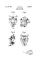
The drawing shows an example of embodiment of the invented object, i.e.:
FIG. 1, a top plan view 0f the safety ski binding in the normal position of use,
FIG. 2, a top plan view of the safety ski binding with the clamping jaw swivelled out,
FIG. 3, a section along the line I-I of FIG. 1, and
FIG. 4, a view of the safety ski binding from below.
The safety ski binding illustrated in the drawing designates by reference numeral 1 the base plate which is fixed with screws 2 unto the ski not shown on the drawing. The base plate 1 has at its longitudinal middle an embossed surface plate 3 directed upwards, and which is provided with a longitudinal slot 4, where the bolt of the screw 5 (FIGS. 3 and 4) finds its guide. The embossing of the surface plate 3 is chosen at such a depth that the head of the screw 5 can move without hindrance. The said ernbossing forms on the base plate 1 a surface plate for the swivelling arm 6, which latter is connected through the screw 5 in a rotating and longitudinal moveably manner with the base plate 1. At the front end of the swivelling arm 6 is fastened the clamping jaw 8 by means of the screw 7.
The surface plate 3 has on its opposite end to the clamping jaw 8 a tapered extension 9, as shown in FIG. 4, which is provided in the shown example with an almost semicircular opening 10, destined to receive the correspondingly formed pin-like latching member 11 (FIG. 3) which on one of its longitudinal sides is provided with a stop face 11 and on its opposite lower end with a rounded-olf 11". The pin-like latching member 11 is under the influence of the pressure spring 12 (FIG. 3) which is embedded within the hollow adjusting screw 13, as shown in FIG. 3.
The use and action of the describedpsafety ski binding is as follows:
When skiing the skier exerts various torques on the skis to impose the direction of the run, and which are normally taken by the ski binding. However, as soon as these torques become unvoluntarily large, e.g. due to a fall, presenting a danger for the skier, the yretaining force of the pinlike latching member 11 is overcome so that the clamping jaw 8 can yield under the lateral pressure of the ski boot. The swivelling arm 6, supporting the clamping jaw 8, will at first slightly swing out whereby the pin-like latching member 11 due to its described form disengages against the action of the pressure spring 12 out of the opening 10 (FIG. 4) whereas the clamping jaw 8 takes the slanting position shown in FIG. 2. According to the regulation of the pressure spring 12 with respect to the pin-like latching member 11 the releasing moment can be adapted easily to the various circumstances and needs.
With the described construction of the latching aperture or opening 10 and the corresponding pin-like latching member 11 according to the present invention, there is obtained with extraordinary simple and reliable means that the entire swivelling part is able to slide freely forwardly to the right or left upon lateral slewing or swivelling.
The described safety binding according to the present invention possesses the advantage of being of an extraordinary simple and sturdy construction and being capable of being manufactured at a favorable price.
What is claimed is:
1. A safety ski binding having a clamping jaw at the end of a swivelling arm which is laterally slewable and longitudinally movable and adapted to engage the edge of the sole of a ski boot wherein the improvement comprises a base plate, pivot means pivotally supporting the swivelling arm on said base plate, said pivot means including a single pivot pin, a plate portion, and a single longitudinally extending guide slot for the pivot pin, and a single latch means for latching the swivelling arm in normal skiing position relative to the base plate, the swivelling arm being free of engagement with any restraining surface other than said single latch means and the pivot pin in normal skiing position and in the slewed position being rotatable about the pivot pin in any direction without requiring longitudinal motion of the swivelling arm, said latch means essentially consisting only of an aperture provided in the front end area of the plate portion and of a reciprocally movable latching member for latching the swivelling arm to the base plate, said aperture being semi-circular shaped and cooperating with a correspondingly shaped portion of the latching member, with the straight surface portion of the semi-circular shape being disposed forwardly of the semi-circular surface portion, as viewed in the direction in which longitudinal movement of the swivelling arm is to be stopped, whereby the single latch means simultaneously blocks the forward movement of the swivelling arm and determines the sensitivity of the safety binding to the release torque necessary to release the safety binding by lateral slewing.
2. A safety ski binding according to claim 1, wherein said latching member is provided with a stop face for engagement with the straight surface portion and with rounded-off portions generally opposite the stop face so as to prevent forward movement of the latch member while enabling lateral disengagement thereof out of said aperture.
3. A safety ski binding according to claim 2, further comprising an adjustable pressure spring acting on said latching member.
4. A safety ski binding according to claim 3 wherein said spring is accommodated in a hollow cylindrical adjusting screw.
5. A safety ski binding according to claim 4, wherein said plate portion is in the form of an embossment of the base plate.
6. A safety ski binding according to claim 5, wherein said plate portion is of oval shape.
7. A safety ski binding according to claim 6 wherein said plate portion is provided at its end opposite the clamping jaw with a tapered extension accommodating the latch aperture.
8. A safety ski binding according to claim 7, wherein said slot extends exclusively in the longitudinal direction.
References Cited UNITED STATES PATENTS 2,899,211 I8/1959 Salomon 2SC-11.35 3,224,786 12/1965 Tosalli 280-1135 FOREIGN PATENTS 190,870 8/ 1964 Sweden.
LEO FRIAGLIA, Primary Examiner.
BENJAMIN HERSH, Examiner.
J. H. BRANNEN, J. A. PEKAR, Assistant Examiners.
Applications Claiming Priority (1)
| Application Number | Priority Date | Filing Date | Title |
|---|---|---|---|
| DEG0042908 | 1965-02-23 |
Publications (1)
| Publication Number | Publication Date |
|---|---|
| US3388922A true US3388922A (en) | 1968-06-18 |
Family
ID=7127045
Family Applications (1)
| Application Number | Title | Priority Date | Filing Date |
|---|---|---|---|
| US528647A Expired - Lifetime US3388922A (en) | 1965-02-23 | 1966-02-18 | Safety ski binding |
Country Status (4)
| Country | Link |
|---|---|
| US (1) | US3388922A (en) |
| AT (1) | AT289609B (en) |
| CH (1) | CH437082A (en) |
| DE (1) | DE1478112A1 (en) |
Cited By (2)
| Publication number | Priority date | Publication date | Assignee | Title |
|---|---|---|---|---|
| US20040224214A1 (en) * | 1993-10-12 | 2004-11-11 | Eugene Vamos | Organic fuel cell methods and apparatus |
| US20050003254A1 (en) * | 1993-10-12 | 2005-01-06 | California Institute Of Technology | Direct methanol feed fuel cell and system |
Citations (2)
| Publication number | Priority date | Publication date | Assignee | Title |
|---|---|---|---|---|
| US2899211A (en) * | 1955-05-07 | 1959-08-11 | salomon | |
| US3224786A (en) * | 1962-06-14 | 1965-12-21 | Reuge Sa | Safety stop for ski attachment |
-
1965
- 1965-02-23 DE DE19651478112 patent/DE1478112A1/en active Pending
-
1966
- 1966-02-03 CH CH155466A patent/CH437082A/en unknown
- 1966-02-10 AT AT119066A patent/AT289609B/en not_active IP Right Cessation
- 1966-02-18 US US528647A patent/US3388922A/en not_active Expired - Lifetime
Patent Citations (2)
| Publication number | Priority date | Publication date | Assignee | Title |
|---|---|---|---|---|
| US2899211A (en) * | 1955-05-07 | 1959-08-11 | salomon | |
| US3224786A (en) * | 1962-06-14 | 1965-12-21 | Reuge Sa | Safety stop for ski attachment |
Cited By (10)
| Publication number | Priority date | Publication date | Assignee | Title |
|---|---|---|---|---|
| US20040224214A1 (en) * | 1993-10-12 | 2004-11-11 | Eugene Vamos | Organic fuel cell methods and apparatus |
| US20050003254A1 (en) * | 1993-10-12 | 2005-01-06 | California Institute Of Technology | Direct methanol feed fuel cell and system |
| US20050042487A1 (en) * | 1993-10-12 | 2005-02-24 | California Institute Of Technology | Direct methanol feed fuel cell and system |
| US20060046133A1 (en) * | 1993-10-12 | 2006-03-02 | California Institute Of Technology | Direct methanol feed fuel cell and system |
| US20060105210A1 (en) * | 1993-10-12 | 2006-05-18 | California Institute Of Technology | Direct methanol feed fuel cell and system |
| US20060204810A1 (en) * | 1993-10-12 | 2006-09-14 | Subbarao Surampudi | Organic fuel cell methods and apparatus |
| US7425384B2 (en) | 1993-10-12 | 2008-09-16 | California Institute Of Technology | Direct methanol feed fuel cell and system |
| US7445859B2 (en) | 1993-10-12 | 2008-11-04 | California Institute Of Technology | Organic fuel cell methods and apparatus |
| US7470478B2 (en) | 1993-10-12 | 2008-12-30 | California Institute Of Technology | Direct methanol feed fuel cell and system |
| US7488548B2 (en) | 1993-10-12 | 2009-02-10 | California Institute Of Technology | Direct methanol feed fuel cell and system |
Also Published As
| Publication number | Publication date |
|---|---|
| CH437082A (en) | 1967-05-31 |
| AT289609B (en) | 1971-04-26 |
| DE1478112A1 (en) | 1969-10-02 |
Similar Documents
| Publication | Publication Date | Title |
|---|---|---|
| US3620545A (en) | Safety clamp for ski bindings employing a combined vertical and horizontal swing catch | |
| US4348036A (en) | Safety binding for nordic skis | |
| US3785668A (en) | Safety ski binding system | |
| US3797841A (en) | Safety binding | |
| US3145027A (en) | Safety ski binding | |
| US4753451A (en) | Pivoting ski binding assembly comprising a braking system | |
| US4457534A (en) | Heelholder for safety ski binding | |
| US5118128A (en) | System for mounting a ski binding on a ski | |
| US3677566A (en) | Ski-binding heel mechanism | |
| US3199885A (en) | Fastening device in safety ski bindings | |
| US4479664A (en) | Ski safety binding | |
| US4858946A (en) | Non-sole dependent ski binding | |
| US3388922A (en) | Safety ski binding | |
| GB975488A (en) | Ski bindings | |
| FR2643608B1 (en) | ||
| US2844381A (en) | Automatically releasable safety arrangement for securing a ski to a skier's boot | |
| US3930660A (en) | Ski binding | |
| US4219216A (en) | Nordic ski binding | |
| EP0302309A3 (en) | Toe iron for safety ski bindings | |
| GB1195043A (en) | Skibindings. | |
| US3545782A (en) | Clamping device for safety ski harness | |
| US4533156A (en) | Toe mechanism for a safety ski binding | |
| GB921403A (en) | Safety securing means for skis | |
| US3961802A (en) | Ski binding | |
| EP0016777A1 (en) | Safety ski binding. |