US3365751A - High temperature high pressure apparatus - Google Patents
High temperature high pressure apparatus Download PDFInfo
- Publication number
- US3365751A US3365751A US602446A US60244666A US3365751A US 3365751 A US3365751 A US 3365751A US 602446 A US602446 A US 602446A US 60244666 A US60244666 A US 60244666A US 3365751 A US3365751 A US 3365751A
- Authority
- US
- United States
- Prior art keywords
- die
- pressure
- high pressure
- high temperature
- insulator
- Prior art date
- Legal status (The legal status is an assumption and is not a legal conclusion. Google has not performed a legal analysis and makes no representation as to the accuracy of the status listed.)
- Expired - Lifetime
Links
Images


Classifications
-
- B—PERFORMING OPERATIONS; TRANSPORTING
- B01—PHYSICAL OR CHEMICAL PROCESSES OR APPARATUS IN GENERAL
- B01J—CHEMICAL OR PHYSICAL PROCESSES, e.g. CATALYSIS OR COLLOID CHEMISTRY; THEIR RELEVANT APPARATUS
- B01J3/00—Processes of utilising sub-atmospheric or super-atmospheric pressure to effect chemical or physical change of matter; Apparatus therefor
- B01J3/06—Processes using ultra-high pressure, e.g. for the formation of diamonds; Apparatus therefor, e.g. moulds or dies
- B01J3/065—Presses for the formation of diamonds or boronitrides
-
- B—PERFORMING OPERATIONS; TRANSPORTING
- B30—PRESSES
- B30B—PRESSES IN GENERAL
- B30B11/00—Presses specially adapted for forming shaped articles from material in particulate or plastic state, e.g. briquetting presses, tabletting presses
- B30B11/004—Presses specially adapted for forming shaped articles from material in particulate or plastic state, e.g. briquetting presses, tabletting presses involving the use of very high pressures
Definitions
- the present invention relates to a high temperature high pressure apparatus. More particularly the present invention relates to a high temperature high pressure apparatus comprising a pair of tapered pistons and a die.
- An object of the present invention is to provide a high temperature high pressure apparatus comprising a die and wherein the die has a construction which will endure through many operations.
- An object of the present invention is to provide a high temperature high pressure apparatus having a die of a long life made of inexpensive pressure resisting metal.
- Still another object of the present invention is to prolong the life of the die by protecting the hole of the die with a hollow cylindrical insulator.
- high temperature high pressure apparatus As such high temperature high pressure apparatus are known a high pressure apparatus of Poulter, Bridgman anvil apparatus, Belt apparatus and tetrahedral anvil apparatus. Among them, the Belt apparatus and tetrahedral anvil apparatus are practical.
- the Belt apparatus is a high temperature high pressure apparatus wherein an annular pressure supporting member having a hole of an outwardly spreading conical inner surface is arranged coaxially between a pair of opposed tapered punches.
- a pair of gaskets is provided between the pair of tapered punches and the annular pressure supporting member.
- Said gasket acts to prevent the high pressure in the reaction chamber from leaking out, to insulate electricity and heat between the punch and the annular pressure supporting member and to make the movement of the punch smooth.
- the gasket is made of such pressure resisting and comparatively easily deformable material as pyrophyllite so as to make the movement of the punch smooth. Therefore, due to this easily deformable property, there is a defect that, if the gasket is thick, the high pressure in the reaction chamber will escape to the part of the gasket and no pressure will concentrate in the center of the reaction chamber.
- this gasket As the hole in the annular pressure supporting member has an outwardly spreading conical surface and is of a shape expanding inward in the central part, the gasket is the thinnest in the part near the central part in the reaction chamber where the temperature and pressure are the highest. Therefore, in spite of the gasket, the inner surface of the hole in the annular pressure supporting member is liable to be influenced by the high temperature and high pressure. Further, in such part, as the upper and lower gaskets are merely in contact with each other in the end parts, the high temperature and high pressure in the reaction chamber are likely to escape through the clearance between the gaskets and to be transmitted to the above mentioned inner surface of the hole.
- the inner surface of the hole in the annular pressure supporting member is an outwardly spreading conical surface. But the shape is so complicated as to be difficult to make. It is all the more difiicult to make the hole specifically'because the annular pressure supporting member is made of a very hard material (very hard alloy) to resist pressures.
- the very hard alloy which is a constituting material of the punch and annular pressure supporting member can not endure such high pressure as several ten thousand atmospheres, it is diflicult to enlarge the apparatus in order to generate a higher pressure or to increase the production.
- the present invention is a high temperature high pressure apparatus in which these problems have been solved and a die corresponding to the above described annular pressure supporting member is so made as to be endurable to many times of uses and to be able to be made of a material comparatively low in the pressure resistance.
- a hollow cylindrical insulator for protecting the inside wall of the hole of the die.
- the hole of the die to be used is cylindrical so that the die may be easily made.
- a hollow cylindrical insulator made of a rigid and electrically and thermally insulative refractory metal oxide. It is fitted in the above mentioned cylindrical hole. The thickness of the wall of said hollow.
- the high temperature high pressure apparatus of the present invention comprising a pair of tapered pistons or punch members each having a truncated part and opposed to each other and a die having a central cylindrical hole and conical holes adjacent to it and each having a tapered surface of an apex angle larger than an apex angle of the above mentioned piston is characterized in that (1) a hollow cylindrical insulatoris fitted in the above mentioned cylindrical hole of the die,
- said hollow cylindrical insulator is made of a rigid and electrically and thermally insulative refractory metal oxide
- the diameter of the truncated circular face portion of the tapered piston is made substantially equal to theinside diameter of the above mentioned hollow cylindrical insulator and (3) the pressurized reaction chamber is defined by the circular end faces of the truncated parts of thetapered pistons and the inside wall of the above mentioned hollow cylindrical insulator.
- a modification of the high temperature high pressure apparatus consists of the apparatus described above, wherein said cylindrical hole and conical holes are separated by intermediate frustoconical holes at angle to the first mentioned holes, the surfaces of the second mentioned intermediate conical respectively.
- and 16 are guides made of phenol-formaldehyde resin to hold the die in the regular position in pressing the pistons 1 and 2 and to insulate the die. from said pistons.
- 17 and 18 are bars made of copper I and connected to an electric source (not shown) so as to be conductors to feed an electric current tov heat the reaction chamber. 7 i
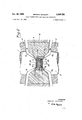
- FIGURE 2 shows a high temperature "high pressure apparatus according to first embodiment of'the present invention.
- the reference numerals have same significance as in'FIGURE l.
- 3 is a die
- a A is a surface of the cylindrical hole (parallel to thecompression direction)
- a 13 is a (surface of the) conical hole having an angle larger than that of the piston.
- E is a hollow cylindrical insulator made of rigid and electrically and thermally insulative refractory metal oxide.
- the hollow cylinder C C C C is afreaction chamber to be filled with graphite and a metal in the synthesis of diamond. 1
- pistons having truncated flat end surfaces C 0 and C 0 and frusto-conical tapered surfaces C D; and C D respectively.
- the pressure in the truncated'parts of the pistons will be the highest.
- the wall A A of the cylindrical hole of the die will be subjected to only a pressure inversely proportional to the square of the diameters Of C C and A A I
- the reaction chamber is heated by directly passing an electric current through the pistons 1 and z, the heat will reach A A through the cylindrical insulator E and therefore the temperature rise ofthe wall will be less 7 than in the conventional apparatus. 7
- FIGURE'3 shows a high temperature high pressure apparatus according to a second embodiment of the present invention in which the pressure resistance and capacity holes having an apex angle equal no greater than the apex angle of the tapered part of the pistons and the surfaces pressure apparatus with embodies the present invention;
- FIGURE 2 is an enlarged sectional view of one form of the high temperature high pressure apparatus of the present invention.
- FIGURE 3 is an enlarged sectional view of a further form of the high temperature high pressure apparatus of the present invention.
- 1 and 2 are tapered pistons made of a tungsten carbide-cobalt alloy, reinforced with spring steel rings, 4, 7 and 5, 8, having a high tensile strength and protected outside with rings 10 and 11 made of a soft steel to prevent danger in the case. of damage caused'at the time of pressure application
- 3 is a die having a cylindrical hole and conical holes, made of tungsten carbide-cobalt alloy, reinforced with spring steel rings 6 and 9 having a high tensile strength and protected outside with a ring 12 made of a soft steel for safety at the time of pressure application.
- 13 and 14 are electrical insulators made of phenol (-formaldehyde) resin to insulate the pistons 1 and 2 from press plates 19 and 19,
- FIGURE 3 is a die
- a A is a surface of the cylindrical hole parallel to the compressive direction
- a C is a surface of the second-mentioned conical hole having an apical angle equal to or smaller than the angle of the tapered partof the piston
- C 3 is a (tapered) surface of the conical hole having an angle larger than that of the piston
- E is a hollow cylindrical insulator made of said material
- the hollow part C C C C is a reaction chamber.
- 1 and 2 are pistons each having a tapered part.
- G and G are gaskets located between. the pistons and the second-mentioned conical hole.
- the hollow cylindrical insulator used in the present invention has it as an object to protect the die. Therefore, it is necessary that the above mentioned hollow cylindrical insulator should be made of a rigid substance so as to protect the die from the high pressure and should be made of an electrically and thermally insulative substance so as to protect the die from the high temperature.
- the term rigid used here does not mean theoretically rigid (not deformable by any pressure). In order to make the movement of the piston made of the very hard alloy easy, the hardness of the insulator had better be lower than of the very hard alloy.
- Said term means the hardness of such substance to be actually used as a refractory metal oxide as made as high as possible and is used to distinguish such substance from commercial hard refractory metal oxide.
- high a substance satisfying such properties as are mentioned above may be in the hardness, it must be electrically insulative. Therefore, metals and alloys can not be used.
- Such refractory metal oxide as alumina or magnesia is favorable.
- a hollow cylindrical body is made by such means as molding its powder and sintering it under a high pressure.
- the hollow cylindrical insulator is made of such material, is to be used as replaced for each operation and is not a component part of the die.
- the pressure applied to the inside wall of the hole of the die can be remarkably reduced by the use ofthe hollow cylindrical insulator.
- the inside diameter ofthe cylndrical hole of the die will become larger than the diameter of the inside wall (corresponding to the inside wall of the reaction chamber) of the hollow cylindrical insulator by the above mentioned thickness, the inside wall of the above mentioned hole will be that much away from the center of the reaction chamber which is at the maximum temperature and pressure and therefore the pressure applied to the inside wall of the hole will reduce.
- the rate of the reduction is large. Therefore, by selecting the thickness of the wall of the above mentioned hollow cylindrical body and properly setting the ratio of the diameters of both of those mentioned above, the pressure applied to the die can be reduced so that the die may be made of a material low in the pressure resistance. Further, reversely, even if the same material is used for the die, the pressure in the reaction chamber will be able to be elevated within the endurable limit of the material. In such case, when the above mentioned hollow cylindrical body is not made of a rigid material, the inside diameter C -C will expand due to the pressure and the above mentioned ratio will become so small that the above described efiect will not be obtained.
- the above mentioned hollow cylindrical body is made of a thermally insulative substance
- the high temperature in the reaction chamber will be hard to conduct to the inside wall of the hole of the die and therefore the strength reduction of the die by heat can be prevented. Therefore, the die will be little broken during the operation. According to the present invention, even when the die was used more than 1500 times, it was not damaged and its life was 30 times as long as of any conventional one.
- the above mentioned truncated part of the piston is made substantially equal to the inside diameter of the above mentioned hollow cylindrical body, the above mentioned truncated part will be all used only to press the reaction chamber and therefore the pressure energy applied to the piston will be effectively used.
- the above mentioned hollow cylindrical body is made of a rigid substance (such as a refractory metal oxide), when the truncated part is to push the above mentioned hollow cylindrical body as heretofore, a large energy will be required due to its deformation.
- the part of contact of the die with the piston is so small that breaks occurring due to the deviation of the positions of the piston and the die from each other are considerably less than in the conventional apparatus.
- the temperature applied to the inside wall of the hole of the die can be extremely reduced as described above.
- the temperature applied to the inside wall is made somewhat lower than before, the amount of the charge will be able to be considerably increased and the yield will be able to be increased.
- each of the pistons 1 and 2 had a truncated surface 15 mm. in diameter, a tapered length of 40 mm. and was made of a 5% WC-Co alloy.
- the core ring 3 was made of a 7% WC-Co alloy, 40 mm. thick, mm. in diameter and 24 mm. in inner diameter.
- the thickness at C C was 27 mm.
- the angle of A C was 27 degrees.
- the angle of C B was 45 degrees.
- the insulator E was made of dense MgO of small coef ficient of compression and its porosity was less than 3%.
- Each of the gaskets G and G was made of agalmatolite and was inserted between metal gaskets made of an iron sheet 0.25 mm. thick.
- the rings 20 and 21 were made of a carbon steel of 0.45% C.
- the inulators 22 and 23 were of agalmatolite.
- the plates 24 and 25 were of nickel.
- the charge 27 consisted of 10 parts by volume of nickel particles of 20 to 30 mesh/in., 1 part by volume of chromium carbide powder of less than 325 mesh/in. and 20 parts by volume of graphite of 60 to 80 mesh/in. These substances were mixed and the mixture was packed into the insulator 26 which is the container of charge 27. Thereafter the insulator 26 containing charge 27 was compressed to mould its shape to that of the reaction chamber. The compressed insulator 26 was inserted within the insulator of small coefficient of compression E. The assembly constructed by the means illustrated above was put in the core ring.
- Such apparatus was arranged as in FIGURE 1 and was put in an oil operated hydraulic press. A pressure was applied to the apparatus through the pistons and plates 19 and 19 of the press so as to produce about 52,000 to 54,000 atmospheres in the reaction chamber. An electric current of 1,200 to 1,500 A. in 1.5 to 1.8 v. was fed to the pistons through the bars 17 and 18. The charge was thus heated for 10 to 15 minutes and was then cooled. When the product was extracted by a conventional chemrcal treatment, a light green diamond could be obtained in a yield of more than 50%.
- a high temperature high pressure apparatus comprising:
- a pair of aligned punch members comprising frusto-conical end portions terminating in fiat parallel confronting circular faces, the diameters of said faces being'substantially equal to the inside diameter of said insulator member, the apex angles of said frustoconical portions of said punch members being smaller than the apex angles of saidfrusto-conical portions of said aperture;
- said central aperture comprises two intermediate frusto-conical portions located intermediate the ends of said cylindrical portion and said first-named frusto conical portions, the apex angles of said intermediate portions being no greaterjthan the apex angles of said frusto-conical portions of said punch members;.said apparatusfurther comprising gasket means positioned'in said intermediate portions of said J central aperture.
Description
Jan. 30, 1968 HIROSHI ISHIZUKA HIGH TEMPERATURE HIGH PRESSURE APPARATUS Filed Nov. 22', 1966 3 Sheets-Sheet 1 INVENTOR: flaws/u V/SH/ZI/KA Jan. 30, 1968 Filed Nov.
HIROSHI KSHIZUKA HIGH TEMPERATURE HIGH PRESSURE APPARATUS I 3 Sheets-Sheet 2 INVENTORI lV/KOS/l/ lS/l/ZUKA ,EZMS
Jan. 30, 1968 HIROSHI ISHIZUKA 3,365,751'
HIGH TEMPERATURE HIGH PRESSURE APPARATUS 3 Sheets-Sheet 5 Filed Nov. 22, 1966 INVENTOR. fl/AOS/l/ ASH/ZVKA BY 4 M u M Arr United States Patent 0' 3,365,751 HIGH TEMPERATURE HIGH PRESSURE APPARATUS Hiroshi Ishizuka, 106 S-chome, Hiratsuka Shinagawa-ku, Tokyo, Japan Continuation-impart of application Ser. No. 300,338, Aug. 6, 1963. This application Nov. 22, 1966, Ser. No. 602,446 Claims priority, application Japan, Aug. 10, 1962, 37/ 34,631 3 Claims. (Cl. 1816.5)
ABSTRACT OF THE DISCLOSURE This application is a continuation-in-part of my copending application Ser. No. 300,338 filed on Aug. 6, 1963, now abandoned.
The present invention relates to a high temperature high pressure apparatus. More particularly the present invention relates to a high temperature high pressure apparatus comprising a pair of tapered pistons and a die.
An object of the present invention is to provide a high temperature high pressure apparatus comprising a die and wherein the die has a construction which will endure through many operations.
An object of the present invention is to provide a high temperature high pressure apparatus having a die of a long life made of inexpensive pressure resisting metal.
Still another object of the present invention is to prolong the life of the die by protecting the hole of the die with a hollow cylindrical insulator.
In order to convert graphite to diamond, there is required an apparatus generating a high temperature of more than about 1200 C. and a high pressure of more than about 50,000 atmospheres. In order to carry out the conversion more efficiently, there is required an apparatus generating a high temperature of more than about 2,000 C. and a high pressure of more than about 100,000 atmospheres. Such apparatus is also useful to carry out a physical conversion or a chemical reaction under a high temperature and pressure of any other substance.
As such high temperature high pressure apparatus are known a high pressure apparatus of Poulter, Bridgman anvil apparatus, Belt apparatus and tetrahedral anvil apparatus. Among them, the Belt apparatus and tetrahedral anvil apparatus are practical.
However, in the latter tetrahedral anvil apparatus, the
mechanism is complicated and the reaction chamber is small as compared with the size of the anvil. Therefore, it has defects that it is not economical and is difficult to make larger.
The Belt apparatus is a high temperature high pressure apparatus wherein an annular pressure supporting member having a hole of an outwardly spreading conical inner surface is arranged coaxially between a pair of opposed tapered punches.
In this apparatus, a pair of gaskets is provided between the pair of tapered punches and the annular pressure supporting member. Said gasket acts to prevent the high pressure in the reaction chamber from leaking out, to insulate electricity and heat between the punch and the annular pressure supporting member and to make the movement of the punch smooth. Thus the gasket is made of such pressure resisting and comparatively easily deformable material as pyrophyllite so as to make the movement of the punch smooth. Therefore, due to this easily deformable property, there is a defect that, if the gasket is thick, the high pressure in the reaction chamber will escape to the part of the gasket and no pressure will concentrate in the center of the reaction chamber.
Further, as regards the shape of this gasket, as the hole in the annular pressure supporting member has an outwardly spreading conical surface and is of a shape expanding inward in the central part, the gasket is the thinnest in the part near the central part in the reaction chamber where the temperature and pressure are the highest. Therefore, in spite of the gasket, the inner surface of the hole in the annular pressure supporting member is liable to be influenced by the high temperature and high pressure. Further, in such part, as the upper and lower gaskets are merely in contact with each other in the end parts, the high temperature and high pressure in the reaction chamber are likely to escape through the clearance between the gaskets and to be transmitted to the above mentioned inner surface of the hole.
On the other hand, it is reasonable for the generation of the high pressure that the inner surface of the hole in the annular pressure supporting member is an outwardly spreading conical surface. But the shape is so complicated as to be difficult to make. It is all the more difiicult to make the hole specifically'because the annular pressure supporting member is made of a very hard material (very hard alloy) to resist pressures.
Further, in this type of apparatus, in order to generate a high pressure, it is considered to be necessary to make the clearance between the punch and the annular pressure supporting member as small as possible so far as the movement of the punch is allowed. Therefore, the diameter of the end surface (truncated part) of the punch and the diameter of the narrowest part of the hole of the annular pressure supporting part are so set as to be as equal to each other as possible. Therefore, the generated high pressure will be applied directly to the annular pressure supporting member. Thus the annular pressure supporting member will be often broken and its life is short. The annular pressure supporting member is made of a costly very hard alloy and the cost of making is also high as described above. Therefore, if its life is short, the diamond produced with it will be very dear.
Further, as the very hard alloy which is a constituting material of the punch and annular pressure supporting member can not endure such high pressure as several ten thousand atmospheres, it is diflicult to enlarge the apparatus in order to generate a higher pressure or to increase the production.
The present invention is a high temperature high pressure apparatus in which these problems have been solved and a die corresponding to the above described annular pressure supporting member is so made as to be endurable to many times of uses and to be able to be made of a material comparatively low in the pressure resistance.
That is to say, in the present invention, in order to attain the above mentioned object, there is used a hollow cylindrical insulator for protecting the inside wall of the hole of the die. Further, the hole of the die to be used is cylindrical so that the die may be easily made.
More particularly, according to the present invention, in order to protect the inside Wall of the circular hole of the die, there is used a hollow cylindrical insulator made of a rigid and electrically and thermally insulative refractory metal oxide. It is fitted in the above mentioned cylindrical hole. The thickness of the wall of said hollow.
high pressure is formed of the truncated parts of the above mentioned pistons and the inside wall' of the hol- 7 low cylindrical insulator.
Therefore, the high temperature high pressure apparatus of the present invention comprising a pair of tapered pistons or punch members each having a truncated part and opposed to each other and a die having a central cylindrical hole and conical holes adjacent to it and each having a tapered surface of an apex angle larger than an apex angle of the above mentioned piston is characterized in that (1) a hollow cylindrical insulatoris fitted in the above mentioned cylindrical hole of the die,
(a) said hollow cylindrical insulator is made of a rigid and electrically and thermally insulative refractory metal oxide,
(b) its outside diameter is substantially equalto the I inside diameter of the above mentioned cylindrical hole so that it is uniformly laterally supported by the die, I
v(c) the thickness of its wall is large enough to protect the inside wall of the above mentioned cylindrical hole from the high temperature and high pressure of the reaction chamber,
(2) the diameter of the truncated circular face portion of the tapered piston is made substantially equal to theinside diameter of the above mentioned hollow cylindrical insulator and (3) the pressurized reaction chamber is defined by the circular end faces of the truncated parts of thetapered pistons and the inside wall of the above mentioned hollow cylindrical insulator.
A modification of the high temperature high pressure apparatus according to the present invention consists of the apparatus described above, wherein said cylindrical hole and conical holes are separated by intermediate frustoconical holes at angle to the first mentioned holes, the surfaces of the second mentioned intermediate conical respectively. and 16 are guides made of phenol-formaldehyde resin to hold the die in the regular position in pressing the pistons 1 and 2 and to insulate the die. from said pistons. 17 and 18 are bars made of copper I and connected to an electric source (not shown) so as to be conductors to feed an electric current tov heat the reaction chamber. 7 i
' FIGURE 2 shows a high temperature "high pressure apparatus according to first embodiment of'the present invention. In FIGURE 2, the reference numerals have same significance as in'FIGURE l. 3 is a die, A A is a surface of the cylindrical hole (parallel to thecompression direction, A 13 is a (surface of the) conical hole having an angle larger than that of the piston. E is a hollow cylindrical insulator made of rigid and electrically and thermally insulative refractory metal oxide. The hollow cylinder C C C C is afreaction chamber to be filled with graphite and a metal in the synthesis of diamond. 1
and 2 are pistons having truncated flat end surfaces C 0 and C 0 and frusto-conical tapered surfaces C D; and C D respectively.
Now, when this apparatus is set in a (oil-operated hydraulic press and a pressure is applied fromthe pistons 1 and 2, the reaction chamber will be compressed by the truncated parts of pistons. In such case, thecylindrical insulator E located in the clearance between the pistons and the die will be partly pushed out to serve as a seal. The coefficient of compressionof the cylindrical insulator E is so small that so much compression of the insulator will not be required in applying the pressure. Therefore, the compression stroke will not be. increased.
In'such case, the pressure in the truncated'parts of the pistons will be the highest. The wall A A of the cylindrical hole of the die will be subjected to only a pressure inversely proportional to the square of the diameters Of C C and A A I When the reaction chamber is heated by directly passing an electric current through the pistons 1 and z, the heat will reach A A through the cylindrical insulator E and therefore the temperature rise ofthe wall will be less 7 than in the conventional apparatus. 7
FIGURE'3 shows a high temperature high pressure apparatus according to a second embodiment of the present invention in which the pressure resistance and capacity holes having an apex angle equal no greater than the apex angle of the tapered part of the pistons and the surfaces pressure apparatus with embodies the present invention;
FIGURE 2 is an enlarged sectional view of one form of the high temperature high pressure apparatus of the present invention; and
FIGURE 3 is an enlarged sectional view of a further form of the high temperature high pressure apparatus of the present invention.
In FIGURE 1, 1 and 2 are tapered pistons made of a tungsten carbide-cobalt alloy, reinforced with spring steel rings, 4, 7 and 5, 8, having a high tensile strength and protected outside with rings 10 and 11 made of a soft steel to prevent danger in the case. of damage caused'at the time of pressure application, 3 is a die having a cylindrical hole and conical holes, made of tungsten carbide-cobalt alloy, reinforced with spring steel rings 6 and 9 having a high tensile strength and protected outside with a ring 12 made of a soft steel for safety at the time of pressure application. 13 and 14 are electrical insulators made of phenol (-formaldehyde) resin to insulate the pistons 1 and 2 from press plates 19 and 19,
that of the apparatus is larger than that of the apparatus shown in FIGURE 2. In FIGURE 3, the reference numerals have significance as FIGURE 1. 3 is a die, A A is a surface of the cylindrical hole parallel to the compressive direction, A C is a surface of the second-mentioned conical hole having an apical angle equal to or smaller than the angle of the tapered partof the piston, C 3 is a (tapered) surface of the conical hole having an angle larger than that of the piston, E is a hollow cylindrical insulator made of said material and the hollow part C C C C is a reaction chamber. 1 and 2 are pistons each having a tapered part. G and G are gaskets located between. the pistons and the second-mentioned conical hole.
As described above, as different from the conventional gasket having it as a principal object to seal the pressure, the hollow cylindrical insulator used in the present invention has it as an object to protect the die. Therefore, it is necessary that the above mentioned hollow cylindrical insulator should be made of a rigid substance so as to protect the die from the high pressure and should be made of an electrically and thermally insulative substance so as to protect the die from the high temperature. The term rigid used here does not mean theoretically rigid (not deformable by any pressure). In order to make the movement of the piston made of the very hard alloy easy, the hardness of the insulator had better be lower than of the very hard alloy. Said term means the hardness of such substance to be actually used as a refractory metal oxide as made as high as possible and is used to distinguish such substance from commercial hard refractory metal oxide. However, high a substance satisfying such properties as are mentioned above may be in the hardness, it must be electrically insulative. Therefore, metals and alloys can not be used. Such refractory metal oxide as alumina or magnesia is favorable. A hollow cylindrical body is made by such means as molding its powder and sintering it under a high pressure. The hollow cylindrical insulator is made of such material, is to be used as replaced for each operation and is not a component part of the die. In the actual operation, a container containing a specimen is put into the hollow cylindrical insulator and then the insulator is fitted into the cylindrical hole of the die. The insulator is so cheap that, even if it is replaced for each operation, it will be economical as the life of die will elongate.
As the present invention is formed as mentioned above, it has such effects as are described below.
First of all, the pressure applied to the inside wall of the hole of the die can be remarkably reduced by the use ofthe hollow cylindrical insulator. Speaking comprehensibly though not technically correctly, when the wall of the hollow cylindrical insulator has a certain thickness, the inside diameter ofthe cylndrical hole of the die will become larger than the diameter of the inside wall (corresponding to the inside wall of the reaction chamber) of the hollow cylindrical insulator by the above mentioned thickness, the inside wall of the above mentioned hole will be that much away from the center of the reaction chamber which is at the maximum temperature and pressure and therefore the pressure applied to the inside wall of the hole will reduce. According to the dynamical calculation, it is approximately presumed that a pressure inversely proportional to the square of the ratio of the inside dameter C -C of the above mentioned hollow cylindrical body to the inside diameter A A of the above mentioned hole will be applied to the inside diameter A A of the cylindrical hole of the die.
Therefore, the rate of the reduction is large. Therefore, by selecting the thickness of the wall of the above mentioned hollow cylindrical body and properly setting the ratio of the diameters of both of those mentioned above, the pressure applied to the die can be reduced so that the die may be made of a material low in the pressure resistance. Further, reversely, even if the same material is used for the die, the pressure in the reaction chamber will be able to be elevated within the endurable limit of the material. In such case, when the above mentioned hollow cylindrical body is not made of a rigid material, the inside diameter C -C will expand due to the pressure and the above mentioned ratio will become so small that the above described efiect will not be obtained.
Secondly, as the above mentioned hollow cylindrical body is made of a thermally insulative substance, the high temperature in the reaction chamber will be hard to conduct to the inside wall of the hole of the die and therefore the strength reduction of the die by heat can be prevented. Therefore, the die will be little broken during the operation. According to the present invention, even when the die was used more than 1500 times, it was not damaged and its life was 30 times as long as of any conventional one.
Thirdly, as the diameter of the truncated part of the piston is made substantially equal to the inside diameter of the above mentioned hollow cylindrical body, the above mentioned truncated part will be all used only to press the reaction chamber and therefore the pressure energy applied to the piston will be effectively used. Specifically, in the present invention, as the above mentioned hollow cylindrical body is made of a rigid substance (such as a refractory metal oxide), when the truncated part is to push the above mentioned hollow cylindrical body as heretofore, a large energy will be required due to its deformation.
Fourthly, the part of contact of the die with the piston is so small that breaks occurring due to the deviation of the positions of the piston and the die from each other are considerably less than in the conventional apparatus.
Further, as the above mentioned hollow cylindrical body is of an electric and thermal insulator, when the reaction chamber is to be charged with reaction substances of the same diameter, the temperature applied to the inside wall of the hole of the die can be extremely reduced as described above. However, if the temperature applied to the inside wall is made somewhat lower than before, the amount of the charge will be able to be considerably increased and the yield will be able to be increased.
' An example of a reaction carried out by using the ap- V paratus of the present invention in a high temperature and high pressure state will now be described.
In this example, in FIGURE 3, each of the pistons 1 and 2 had a truncated surface 15 mm. in diameter, a tapered length of 40 mm. and was made of a 5% WC-Co alloy. The core ring 3 was made of a 7% WC-Co alloy, 40 mm. thick, mm. in diameter and 24 mm. in inner diameter. The thickness at C C was 27 mm. The angle of A C was 27 degrees. The angle of C B was 45 degrees. The insulator E was made of dense MgO of small coef ficient of compression and its porosity was less than 3%. Each of the gaskets G and G was made of agalmatolite and was inserted between metal gaskets made of an iron sheet 0.25 mm. thick.
The rings 20 and 21 were made of a carbon steel of 0.45% C. The inulators 22 and 23 were of agalmatolite. The plates 24 and 25 were of nickel. The charge 27 consisted of 10 parts by volume of nickel particles of 20 to 30 mesh/in., 1 part by volume of chromium carbide powder of less than 325 mesh/in. and 20 parts by volume of graphite of 60 to 80 mesh/in. These substances were mixed and the mixture was packed into the insulator 26 which is the container of charge 27. Thereafter the insulator 26 containing charge 27 was compressed to mould its shape to that of the reaction chamber. The compressed insulator 26 was inserted within the insulator of small coefficient of compression E. The assembly constructed by the means illustrated above was put in the core ring.
Such apparatus was arranged as in FIGURE 1 and was put in an oil operated hydraulic press. A pressure was applied to the apparatus through the pistons and plates 19 and 19 of the press so as to produce about 52,000 to 54,000 atmospheres in the reaction chamber. An electric current of 1,200 to 1,500 A. in 1.5 to 1.8 v. was fed to the pistons through the bars 17 and 18. The charge was thus heated for 10 to 15 minutes and was then cooled. When the product was extracted by a conventional chemrcal treatment, a light green diamond could be obtained in a yield of more than 50%.
t When sltlich operation was repeated more than 1,500
unes 1n e present a aratus, no darn all in the die. pp age appalled at On the contrary, when the above example was repeated except that agalmatolite, whose coefficient of compression was several times that of the rigid substance described above, was used as the material of E, the pressure was applied directly to the inner wall of the die and as a result the die was damaged after being used about 50 times.
What I claim is:
1. A high temperature high pressure apparatus comprising:
(l) a die having a central aperture formed therein, said aperture comprising a central cylindrical portion and two frusto-conical end portions which diverge outwardly from the ends of said cylindrical portion;
(2) a hollow cylindrical insulator member removably fitted coaxially into said cylindrical portion of said aperture, the external diameter of said insulator being substantially equal to the diameter of said cylindrical portion and its length being substantially coextensive with said'cylindrical portion;
(3) a pair of aligned punch members comprising frusto-conical end portions terminating in fiat parallel confronting circular faces, the diameters of said faces being'substantially equal to the inside diameter of said insulator member, the apex angles of said frustoconical portions of said punch members being smaller than the apex angles of saidfrusto-conical portions of said aperture;
(4) pressure means for forcing said faces toward each other to close the ends of said insulator member, thereby defining a pressurized reaction chamber in the interior or" said insulator member; and
(5 means for passing an electric current between said faces for producing resistive heating of an electrically conductive charge in said reaction chamber.
2. Apparatus according to claim 1, wherein said central aperture comprises two intermediate frusto-conical portions located intermediate the ends of said cylindrical portion and said first-named frusto conical portions, the apex angles of said intermediate portions being no greaterjthan the apex angles of said frusto-conical portions of said punch members;.said apparatusfurther comprising gasket means positioned'in said intermediate portions of said J central aperture.
3. Apparatus according to claim L'Wherein saidinsulator member is formed :of a refractory metallic oxide selected from the group consisting of alumina and magnesia.
References Cited V UNITED STATES PATENTS 2,554,499 5/1951 PoulteL' 2,941,241 6/1960 Strong.
2,941,248 6/1960 Hall. I 3,067,465 12/1962 Giardiniet al. 7 3,137,896 6/1964 Daniels.
WILLIAM J. STEPHENSON, Primary Era miner.
Applications Claiming Priority (1)
| Application Number | Priority Date | Filing Date | Title |
|---|---|---|---|
| JP3463162 | 1962-08-10 |
Publications (1)
| Publication Number | Publication Date |
|---|---|
| US3365751A true US3365751A (en) | 1968-01-30 |
Family
ID=12419733
Family Applications (1)
| Application Number | Title | Priority Date | Filing Date |
|---|---|---|---|
| US602446A Expired - Lifetime US3365751A (en) | 1962-08-10 | 1966-11-22 | High temperature high pressure apparatus |
Country Status (2)
| Country | Link |
|---|---|
| US (1) | US3365751A (en) |
| GB (1) | GB1058449A (en) |
Cited By (7)
| Publication number | Priority date | Publication date | Assignee | Title |
|---|---|---|---|---|
| US3543347A (en) * | 1967-08-25 | 1970-12-01 | Hiroshi Ishizuka | Ultrahigh pressure apparatus |
| US4118161A (en) * | 1975-06-12 | 1978-10-03 | Kennametal Inc. | High temperature, high pressure apparatus having a ductile driver element |
| US4385881A (en) * | 1980-04-18 | 1983-05-31 | Hiroshi Ishizuka | Ultrahigh pressure apparatus |
| US6045885A (en) * | 1998-09-01 | 2000-04-04 | Cheney; James E. | High pressure, high temperature gasket |
| US20050153010A1 (en) * | 2004-01-13 | 2005-07-14 | Chien-Min Sung | High pressure split die and associated methods |
| US20060032431A1 (en) * | 2004-01-13 | 2006-02-16 | Chien-Min Sung | High pressure crystal growth apparatuses and associated methods |
| US20100068122A1 (en) * | 2008-08-25 | 2010-03-18 | Chien-Min Sung | Gem Growth Cubic Press and Associated Methods |
Citations (5)
| Publication number | Priority date | Publication date | Assignee | Title |
|---|---|---|---|---|
| US2554499A (en) * | 1947-09-08 | 1951-05-29 | Armour Res Found | High-pressure apparatus |
| US2941241A (en) * | 1955-02-14 | 1960-06-21 | Gen Electric | High temperature high pressure apparatus |
| US2941248A (en) * | 1958-01-06 | 1960-06-21 | Gen Electric | High temperature high pressure apparatus |
| US3067465A (en) * | 1961-04-05 | 1962-12-11 | Armando A Giardini | Pressure and temperature sensing device for high pressure apparatus |
| US3137896A (en) * | 1961-09-27 | 1964-06-23 | Union Carbide Corp | Apparatus for subjecting matter to ultra-high pressure |
-
1963
- 1963-08-02 GB GB30810/63A patent/GB1058449A/en not_active Expired
-
1966
- 1966-11-22 US US602446A patent/US3365751A/en not_active Expired - Lifetime
Patent Citations (5)
| Publication number | Priority date | Publication date | Assignee | Title |
|---|---|---|---|---|
| US2554499A (en) * | 1947-09-08 | 1951-05-29 | Armour Res Found | High-pressure apparatus |
| US2941241A (en) * | 1955-02-14 | 1960-06-21 | Gen Electric | High temperature high pressure apparatus |
| US2941248A (en) * | 1958-01-06 | 1960-06-21 | Gen Electric | High temperature high pressure apparatus |
| US3067465A (en) * | 1961-04-05 | 1962-12-11 | Armando A Giardini | Pressure and temperature sensing device for high pressure apparatus |
| US3137896A (en) * | 1961-09-27 | 1964-06-23 | Union Carbide Corp | Apparatus for subjecting matter to ultra-high pressure |
Cited By (12)
| Publication number | Priority date | Publication date | Assignee | Title |
|---|---|---|---|---|
| US3543347A (en) * | 1967-08-25 | 1970-12-01 | Hiroshi Ishizuka | Ultrahigh pressure apparatus |
| US4118161A (en) * | 1975-06-12 | 1978-10-03 | Kennametal Inc. | High temperature, high pressure apparatus having a ductile driver element |
| US4119708A (en) * | 1975-06-12 | 1978-10-10 | Kennametal Inc. | High temperature, high pressure process utilizing a ductile driver element |
| US4385881A (en) * | 1980-04-18 | 1983-05-31 | Hiroshi Ishizuka | Ultrahigh pressure apparatus |
| US6045885A (en) * | 1998-09-01 | 2000-04-04 | Cheney; James E. | High pressure, high temperature gasket |
| US20050153010A1 (en) * | 2004-01-13 | 2005-07-14 | Chien-Min Sung | High pressure split die and associated methods |
| US20060032431A1 (en) * | 2004-01-13 | 2006-02-16 | Chien-Min Sung | High pressure crystal growth apparatuses and associated methods |
| US20060032429A1 (en) * | 2004-01-13 | 2006-02-16 | Chien-Min Sung | High pressure split die and associated methods |
| US7128547B2 (en) | 2004-01-13 | 2006-10-31 | Chien-Min Sung | High pressure split die and associated methods |
| US7371280B2 (en) | 2004-01-13 | 2008-05-13 | Chien-Min Sung | High pressure crystal growth apparatuses and associated methods |
| US7540075B2 (en) | 2004-01-13 | 2009-06-02 | Chien-Min Sung | Method of applying high pressures to a high pressure assembly |
| US20100068122A1 (en) * | 2008-08-25 | 2010-03-18 | Chien-Min Sung | Gem Growth Cubic Press and Associated Methods |
Also Published As
| Publication number | Publication date |
|---|---|
| GB1058449A (en) | 1967-02-08 |
Similar Documents
| Publication | Publication Date | Title |
|---|---|---|
| US3061877A (en) | High-pressure die | |
| US2195297A (en) | Method and apparatus for making hot pressed hard metal compositions | |
| EP0032545A1 (en) | Process and device for transforming material using high pressures and temperatures | |
| US3365751A (en) | High temperature high pressure apparatus | |
| RU196265U1 (en) | Device for electropulse pressing of powder materials | |
| US3107395A (en) | High pressure high temperature apparatus | |
| US2651952A (en) | Die for extruding compressed powder rods | |
| US3213491A (en) | Hardcoated mold press die | |
| US2941252A (en) | Reaction vessel | |
| US3137896A (en) | Apparatus for subjecting matter to ultra-high pressure | |
| US3075245A (en) | Plural reaction chamber press for high pressures | |
| US5244368A (en) | High pressure/high temperature piston-cylinder apparatus | |
| US3350743A (en) | High temperature and high pressure apparatus | |
| US3546413A (en) | High temperature high pressure apparatus | |
| US3082477A (en) | Plunger dies | |
| US3191231A (en) | High pressure high temperature punch member | |
| JPS6059008B2 (en) | Improved ultra-high pressure equipment | |
| US3895894A (en) | Device for generating high pressures and temperatures | |
| US3543347A (en) | Ultrahigh pressure apparatus | |
| US3492695A (en) | Ultra high pressure-high temperature apparatus | |
| US3030661A (en) | High pressure reaction vessel | |
| US3559242A (en) | High pressure cells | |
| RU201841U1 (en) | Device for electropulse pressing of powder materials | |
| US2022528A (en) | Apparatus for sintering refractory material | |
| RU220034U1 (en) | Device for electropulse pressing of tablets with a hole made of electrically conductive powders |