US3349941A - Compartmented container package - Google Patents
Compartmented container package Download PDFInfo
- Publication number
- US3349941A US3349941A US545031A US54503166A US3349941A US 3349941 A US3349941 A US 3349941A US 545031 A US545031 A US 545031A US 54503166 A US54503166 A US 54503166A US 3349941 A US3349941 A US 3349941A
- Authority
- US
- United States
- Prior art keywords
- container
- inner container
- containers
- side wall
- groove
- Prior art date
- Legal status (The legal status is an assumption and is not a legal conclusion. Google has not performed a legal analysis and makes no representation as to the accuracy of the status listed.)
- Expired - Lifetime
Links
Images

Classifications
-
- B—PERFORMING OPERATIONS; TRANSPORTING
- B65—CONVEYING; PACKING; STORING; HANDLING THIN OR FILAMENTARY MATERIAL
- B65D—CONTAINERS FOR STORAGE OR TRANSPORT OF ARTICLES OR MATERIALS, e.g. BAGS, BARRELS, BOTTLES, BOXES, CANS, CARTONS, CRATES, DRUMS, JARS, TANKS, HOPPERS, FORWARDING CONTAINERS; ACCESSORIES, CLOSURES, OR FITTINGS THEREFOR; PACKAGING ELEMENTS; PACKAGES
- B65D81/00—Containers, packaging elements, or packages, for contents presenting particular transport or storage problems, or adapted to be used for non-packaging purposes after removal of contents
- B65D81/32—Containers, packaging elements, or packages, for contents presenting particular transport or storage problems, or adapted to be used for non-packaging purposes after removal of contents for packaging two or more different materials which must be maintained separate prior to use in admixture
- B65D81/3216—Rigid containers disposed one within the other
-
- B—PERFORMING OPERATIONS; TRANSPORTING
- B65—CONVEYING; PACKING; STORING; HANDLING THIN OR FILAMENTARY MATERIAL
- B65D—CONTAINERS FOR STORAGE OR TRANSPORT OF ARTICLES OR MATERIALS, e.g. BAGS, BARRELS, BOTTLES, BOXES, CANS, CARTONS, CRATES, DRUMS, JARS, TANKS, HOPPERS, FORWARDING CONTAINERS; ACCESSORIES, CLOSURES, OR FITTINGS THEREFOR; PACKAGING ELEMENTS; PACKAGES
- B65D43/00—Lids or covers for rigid or semi-rigid containers
- B65D43/02—Removable lids or covers
- B65D43/0202—Removable lids or covers without integral tamper element
- B65D43/0204—Removable lids or covers without integral tamper element secured by snapping over beads or projections
- B65D43/021—Removable lids or covers without integral tamper element secured by snapping over beads or projections only on the inside, or a part turned to the inside, of the mouth
-
- B—PERFORMING OPERATIONS; TRANSPORTING
- B65—CONVEYING; PACKING; STORING; HANDLING THIN OR FILAMENTARY MATERIAL
- B65D—CONTAINERS FOR STORAGE OR TRANSPORT OF ARTICLES OR MATERIALS, e.g. BAGS, BARRELS, BOTTLES, BOXES, CANS, CARTONS, CRATES, DRUMS, JARS, TANKS, HOPPERS, FORWARDING CONTAINERS; ACCESSORIES, CLOSURES, OR FITTINGS THEREFOR; PACKAGING ELEMENTS; PACKAGES
- B65D51/00—Closures not otherwise provided for
- B65D51/16—Closures not otherwise provided for with means for venting air or gas
- B65D51/1633—Closures not otherwise provided for with means for venting air or gas whereby venting occurs by automatic opening of the closure, container or other element
- B65D51/1661—Closures not otherwise provided for with means for venting air or gas whereby venting occurs by automatic opening of the closure, container or other element by means of a passage for the escape of gas between the closure and the lip of the container mouth
- B65D51/1666—Closures not otherwise provided for with means for venting air or gas whereby venting occurs by automatic opening of the closure, container or other element by means of a passage for the escape of gas between the closure and the lip of the container mouth the closure being for a box-like container
-
- B—PERFORMING OPERATIONS; TRANSPORTING
- B65—CONVEYING; PACKING; STORING; HANDLING THIN OR FILAMENTARY MATERIAL
- B65D—CONTAINERS FOR STORAGE OR TRANSPORT OF ARTICLES OR MATERIALS, e.g. BAGS, BARRELS, BOTTLES, BOXES, CANS, CARTONS, CRATES, DRUMS, JARS, TANKS, HOPPERS, FORWARDING CONTAINERS; ACCESSORIES, CLOSURES, OR FITTINGS THEREFOR; PACKAGING ELEMENTS; PACKAGES
- B65D2543/00—Lids or covers essentially for box-like containers
- B65D2543/00009—Details of lids or covers for rigid or semi-rigid containers
- B65D2543/00018—Overall construction of the lid
- B65D2543/00027—Stackable lids or covers
-
- B—PERFORMING OPERATIONS; TRANSPORTING
- B65—CONVEYING; PACKING; STORING; HANDLING THIN OR FILAMENTARY MATERIAL
- B65D—CONTAINERS FOR STORAGE OR TRANSPORT OF ARTICLES OR MATERIALS, e.g. BAGS, BARRELS, BOTTLES, BOXES, CANS, CARTONS, CRATES, DRUMS, JARS, TANKS, HOPPERS, FORWARDING CONTAINERS; ACCESSORIES, CLOSURES, OR FITTINGS THEREFOR; PACKAGING ELEMENTS; PACKAGES
- B65D2543/00—Lids or covers essentially for box-like containers
- B65D2543/00009—Details of lids or covers for rigid or semi-rigid containers
- B65D2543/00018—Overall construction of the lid
- B65D2543/00064—Shape of the outer periphery
- B65D2543/00074—Shape of the outer periphery curved
- B65D2543/00092—Shape of the outer periphery curved circular
-
- B—PERFORMING OPERATIONS; TRANSPORTING
- B65—CONVEYING; PACKING; STORING; HANDLING THIN OR FILAMENTARY MATERIAL
- B65D—CONTAINERS FOR STORAGE OR TRANSPORT OF ARTICLES OR MATERIALS, e.g. BAGS, BARRELS, BOTTLES, BOXES, CANS, CARTONS, CRATES, DRUMS, JARS, TANKS, HOPPERS, FORWARDING CONTAINERS; ACCESSORIES, CLOSURES, OR FITTINGS THEREFOR; PACKAGING ELEMENTS; PACKAGES
- B65D2543/00—Lids or covers essentially for box-like containers
- B65D2543/00009—Details of lids or covers for rigid or semi-rigid containers
- B65D2543/00018—Overall construction of the lid
- B65D2543/00259—Materials used
- B65D2543/00296—Plastic
-
- B—PERFORMING OPERATIONS; TRANSPORTING
- B65—CONVEYING; PACKING; STORING; HANDLING THIN OR FILAMENTARY MATERIAL
- B65D—CONTAINERS FOR STORAGE OR TRANSPORT OF ARTICLES OR MATERIALS, e.g. BAGS, BARRELS, BOTTLES, BOXES, CANS, CARTONS, CRATES, DRUMS, JARS, TANKS, HOPPERS, FORWARDING CONTAINERS; ACCESSORIES, CLOSURES, OR FITTINGS THEREFOR; PACKAGING ELEMENTS; PACKAGES
- B65D2543/00—Lids or covers essentially for box-like containers
- B65D2543/00009—Details of lids or covers for rigid or semi-rigid containers
- B65D2543/00342—Central part of the lid
- B65D2543/00398—Reinforcing ribs in the central part of the closure
- B65D2543/00407—Reinforcing ribs in the central part of the closure radial
-
- B—PERFORMING OPERATIONS; TRANSPORTING
- B65—CONVEYING; PACKING; STORING; HANDLING THIN OR FILAMENTARY MATERIAL
- B65D—CONTAINERS FOR STORAGE OR TRANSPORT OF ARTICLES OR MATERIALS, e.g. BAGS, BARRELS, BOTTLES, BOXES, CANS, CARTONS, CRATES, DRUMS, JARS, TANKS, HOPPERS, FORWARDING CONTAINERS; ACCESSORIES, CLOSURES, OR FITTINGS THEREFOR; PACKAGING ELEMENTS; PACKAGES
- B65D2543/00—Lids or covers essentially for box-like containers
- B65D2543/00009—Details of lids or covers for rigid or semi-rigid containers
- B65D2543/00444—Contact between the container and the lid
- B65D2543/00481—Contact between the container and the lid on the inside or the outside of the container
- B65D2543/0049—Contact between the container and the lid on the inside or the outside of the container on the inside, or a part turned to the inside of the mouth of the container
- B65D2543/00509—Cup
-
- B—PERFORMING OPERATIONS; TRANSPORTING
- B65—CONVEYING; PACKING; STORING; HANDLING THIN OR FILAMENTARY MATERIAL
- B65D—CONTAINERS FOR STORAGE OR TRANSPORT OF ARTICLES OR MATERIALS, e.g. BAGS, BARRELS, BOTTLES, BOXES, CANS, CARTONS, CRATES, DRUMS, JARS, TANKS, HOPPERS, FORWARDING CONTAINERS; ACCESSORIES, CLOSURES, OR FITTINGS THEREFOR; PACKAGING ELEMENTS; PACKAGES
- B65D2543/00—Lids or covers essentially for box-like containers
- B65D2543/00009—Details of lids or covers for rigid or semi-rigid containers
- B65D2543/00444—Contact between the container and the lid
- B65D2543/00481—Contact between the container and the lid on the inside or the outside of the container
- B65D2543/00537—Contact between the container and the lid on the inside or the outside of the container on the outside, or a part turned to the outside of the mouth of the container
-
- B—PERFORMING OPERATIONS; TRANSPORTING
- B65—CONVEYING; PACKING; STORING; HANDLING THIN OR FILAMENTARY MATERIAL
- B65D—CONTAINERS FOR STORAGE OR TRANSPORT OF ARTICLES OR MATERIALS, e.g. BAGS, BARRELS, BOTTLES, BOXES, CANS, CARTONS, CRATES, DRUMS, JARS, TANKS, HOPPERS, FORWARDING CONTAINERS; ACCESSORIES, CLOSURES, OR FITTINGS THEREFOR; PACKAGING ELEMENTS; PACKAGES
- B65D2543/00—Lids or covers essentially for box-like containers
- B65D2543/00009—Details of lids or covers for rigid or semi-rigid containers
- B65D2543/00444—Contact between the container and the lid
- B65D2543/00481—Contact between the container and the lid on the inside or the outside of the container
- B65D2543/00555—Contact between the container and the lid on the inside or the outside of the container on both the inside and the outside
-
- B—PERFORMING OPERATIONS; TRANSPORTING
- B65—CONVEYING; PACKING; STORING; HANDLING THIN OR FILAMENTARY MATERIAL
- B65D—CONTAINERS FOR STORAGE OR TRANSPORT OF ARTICLES OR MATERIALS, e.g. BAGS, BARRELS, BOTTLES, BOXES, CANS, CARTONS, CRATES, DRUMS, JARS, TANKS, HOPPERS, FORWARDING CONTAINERS; ACCESSORIES, CLOSURES, OR FITTINGS THEREFOR; PACKAGING ELEMENTS; PACKAGES
- B65D2543/00—Lids or covers essentially for box-like containers
- B65D2543/00009—Details of lids or covers for rigid or semi-rigid containers
- B65D2543/00444—Contact between the container and the lid
- B65D2543/00592—Snapping means
- B65D2543/00601—Snapping means on the container
- B65D2543/00611—Profiles
- B65D2543/0062—Groove or hollow bead
-
- B—PERFORMING OPERATIONS; TRANSPORTING
- B65—CONVEYING; PACKING; STORING; HANDLING THIN OR FILAMENTARY MATERIAL
- B65D—CONTAINERS FOR STORAGE OR TRANSPORT OF ARTICLES OR MATERIALS, e.g. BAGS, BARRELS, BOTTLES, BOXES, CANS, CARTONS, CRATES, DRUMS, JARS, TANKS, HOPPERS, FORWARDING CONTAINERS; ACCESSORIES, CLOSURES, OR FITTINGS THEREFOR; PACKAGING ELEMENTS; PACKAGES
- B65D2543/00—Lids or covers essentially for box-like containers
- B65D2543/00009—Details of lids or covers for rigid or semi-rigid containers
- B65D2543/00444—Contact between the container and the lid
- B65D2543/00592—Snapping means
- B65D2543/00601—Snapping means on the container
- B65D2543/00675—Periphery concerned
- B65D2543/00685—Totality
-
- B—PERFORMING OPERATIONS; TRANSPORTING
- B65—CONVEYING; PACKING; STORING; HANDLING THIN OR FILAMENTARY MATERIAL
- B65D—CONTAINERS FOR STORAGE OR TRANSPORT OF ARTICLES OR MATERIALS, e.g. BAGS, BARRELS, BOTTLES, BOXES, CANS, CARTONS, CRATES, DRUMS, JARS, TANKS, HOPPERS, FORWARDING CONTAINERS; ACCESSORIES, CLOSURES, OR FITTINGS THEREFOR; PACKAGING ELEMENTS; PACKAGES
- B65D2543/00—Lids or covers essentially for box-like containers
- B65D2543/00009—Details of lids or covers for rigid or semi-rigid containers
- B65D2543/00444—Contact between the container and the lid
- B65D2543/00592—Snapping means
- B65D2543/00712—Snapping means on the lid
- B65D2543/00722—Profiles
- B65D2543/00731—Groove or hollow bead
-
- B—PERFORMING OPERATIONS; TRANSPORTING
- B65—CONVEYING; PACKING; STORING; HANDLING THIN OR FILAMENTARY MATERIAL
- B65D—CONTAINERS FOR STORAGE OR TRANSPORT OF ARTICLES OR MATERIALS, e.g. BAGS, BARRELS, BOTTLES, BOXES, CANS, CARTONS, CRATES, DRUMS, JARS, TANKS, HOPPERS, FORWARDING CONTAINERS; ACCESSORIES, CLOSURES, OR FITTINGS THEREFOR; PACKAGING ELEMENTS; PACKAGES
- B65D2543/00—Lids or covers essentially for box-like containers
- B65D2543/00009—Details of lids or covers for rigid or semi-rigid containers
- B65D2543/00444—Contact between the container and the lid
- B65D2543/00592—Snapping means
- B65D2543/00712—Snapping means on the lid
- B65D2543/00787—Periphery concerned
- B65D2543/00796—Totality
Definitions
- the present invention relates to a compartmented container package, and more particularly, to a container package composed of a series of discrete elements which subdivide the package into compartments for packaging different foodstuffs or other products in the same container, but in different compartments.
- compartmented container packages have heretofore been proposed in meeting various requirements.
- a compartmented container package has not been developed, however, which meets the demands of certain food products such as, for example, cottage cheese and fresh fruit combinations. These food products have a high moisture content and spoil quite easily, and thus is important to have a sanitary, leak-proof package which provides a hermetic seal between the various compartments in the package, and yet which affords unidirectional venting of gaseous pressure generated by the fermentation of food products contained therein, but without separation of the compartments from each other.
- the ease of assembly and removal of the container compartments from each other, even where there is no problem of gas generation is an important consideration in the development of a commercially acceptable package. Other considerations come into play in meeting the demands of various products, and this will become apparent in the ensuing discussion.
- Still another object of the present invention is the provision of a novel compartmented container package which provides a hermetically sealed environment for the products contained in the compartments of the package while affording unidirectional venting therefrom under certain prescribed conditions soas to be self-venting in character.
- Yet another object of the present invention is to provide a novel compartmented container package which, in addition to the aforementioned objects, assures efiicient storage, separation and dispensing of similarly configured compartments or elements from each other.
- a still further object of the present invention is the provision of a container package of the aforenoted type wherein each element thereof is not only sanitary, leakproof and sturdy, but which also can be economically mas produced under conventional thermoforming techniques as presently known.
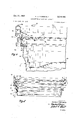
- FIG. 1 is an exploded perspective view of the novel compartmented container package incorporating the features of the present invention
- FIG. 2 is an elevational view, partly in section, of the compartmented container package of the present invention with the elements or components thereof assembled to one another;
- FIG. 3 is an enlarged fragmentary sectional view showing the assembled components or elements of the herein disclosed compartmented container package
- FIG. 4 is also an enlarged fragmentary section view on a slightly smaller scale than FIG. 3, and illustrating the manner in which the component or elements of the package coact with one another in providing unidirectional venting of gaseous pressure emanating from the contents in the compartments of the package;
- FIG. 5 is an enlarged elevational view, partly in section on a slightly smaller scale than FIG. 4 and depicting a plurality of stacked inner compartment container elements, each of which form a part of a compartmented container package as will become apparent.
- a compartmented container package generally designated 10 which includes an outer container 12, an inner container 14, and a lid member 16.
- Each of the element 12, 14 and 16 of the compartmented container package 10 are preferably formed as one-piece, seamless units from thermoplastic material such as high impact polystyrene.
- thermoplastic material such as high impact polystyrene.
- the use of plastic material has gained wide spread acceptance throughout the packaging industry, particularly where one-piece, seamless elements have been employed because of the economical, mass producing capabilities of thermoforming techniques which are being used today by packaging manufacturers on a large scale.
- the outer container 12 is adapted to receive the inner container or compartment 14, the latter in turn receiving the lid member 16, all as is shown in FIGS. 2-3 of the drawings.
- the outer container or tub 12 has a bottom wall 20 which is axially concave upwards in the manner shown in FIG. 2, a circumferential side wall 22 which diverges upwardly and outwardly therefrom, and which terminates in a rim 24 of increased lateral width and height relative to the side wall thickness.
- the rim 24 is rolled or folded back upon itself, and while this is the preferred form, it will be understood that rims which may be crushed or formed as solid beads, and in various shapes, may be employed.
- the rim 24 surrounds the open mouth or open upper end of the container as will be apparent.
- a stacking ring construction 26 including an internal shoulder 28 and an external shoulder 30, the internal shoulder 28 having a smaller minimum diameter by more than twice the side wall thickness of the container so as to provide an intermediate back tapered supporting section 32 which will afford a resilient action to a stack of containers when telescopically received one Within the other as specifically discussed in US. Patent No. 3,139,213, Spaced upwardly from the stacking area 26 of the outer container 12 is an internal groove or lid seat 34 which is formed by radially outwardly offset portions of the container side wall 22.
- the internal groove or lid seat 34 includes a generally horizontally directed lower portion 36 which is integrally connected to the upper internal shoulder 28 of the stack- .ing ring 26, a vertically directed section 38 which deter mines the axially height of the internal groove or lid seat 34, and an inclined, but radially inwardly directed portion 40 which integrally joins or connects the generally vertical section 38 with portions of the side wall 22 in the vicinity of the open mouth of the container 12.
- Various shapes and sizes of internal grooves or lid seats 34 may be employed, and in this connection, reference is made to US. Patent No. 3,061,139 which shows various representative forms and sizes.
- the outer container 12 just described is generally conventionally employed throughout the thin-walled thermoplastic packaging field by many manufacturers.
- the capacity of such containers vary from four to thirty-two ounces depending upon the diameter and axial height of the container, and it is to be understood that the outer container 12 is to be considered with this in mind.
- the inner container 14 includes as best seen in FIG. 2 of the drawings a bottom wall 44 which is axially concave upwards in the same manner as the bottom wall 20 of outer container 12, a circumferentially extending side wall 46 which diverges upwardly and outwardly from the bottom wall 44, and which terminates in the same manner as the outer container 12 in a circumferential rim 48 having an axial height and lateral extent greater than the thickness of the side wall 46.
- the axial height of the side wall 46 is substantially shorter than the side wall 22 of the outer container 12 for telescopic reception of the inner container 14 therein while assuring spacing of the bottom walls 20, 44 of the outer and inner containers respectively a predetermined distance from each other. This will enable food products or the like to be placed within the outer container 12 while the inner container 14 serves as a separator or compartment between the outer container contents and the products received by it as will be apparent.
- the rim or lip portion 48 of the inner container 14 is in the form of a reversely extending skirt portion, having an upper radially outwardly extending wall portion 50 and a depending flange 52 which is spaced laterally outwardly and downwardly from the open upper end of the inner container 14 and which terminates in a free end portion 54 at the lower end of the depending flange 52.
- the minimum distance between the free end portion 54 of the inner container lip or rim portion 48 and adjacent portions of the side wall 46 in the vicinity thereof is large enough to accommodate the lip or rim portion 24 of the outer container 12 therein with the depending flange slightly contacting or resting against outer peripheral areas of the rim portion 24.
- the radial wall 50 and substantial portions of the depending flange 52 extend or project upwardly from the top of the lip or rim portion 24 to facilitate removal of the inner container 14 from the outer container 12 by making it quite easy to change the contour of the rim or lip portion 48 relative to the outer container lip or rim portion 24 when subjected to a predetermined amount of force in a generally radially inward direction.
- This is described in detail in patent application Ser. No. 512,377 filed Dec. 8, 1965, and assigned to the same assignee of the present invention.
- a stacking ring construction 56 including an upper internal shoulder 58, a lower external shoulder 60, and an intermediate supporting section 62 which is reversely tapered with respect to the side wall 46.
- the stacking ring construction 56 of the inner container 14 is the same as the stacking ring construction 26 of the outer container 12 in the sense that the minimum diameter of the internal shoulder 58 is smaller than by more than twice the side will thickness of the external shoulder 60 so as to provide a resilient stack of containers to avoid jamming as is now well known.
- the manner in which the inner containers 14 are stacked relative to one another is readily depicted in FIG. of the drawings.
- At least one pair of similarly configured and dimensioned locking portions 64, 66 which are radially outwardly offset from adjacent portions of the side wall 46.
- the locking portions 64, 66 are axially spaced from each other so that the locking portion 64 engages the lid member 16 in the manner to be described hereinafter with the locking portion 66 received within the internal groove 34 of the outer container 12 to releasably retain the various elements of the compartmented container package in assembled relationship.
- the locking portion 66 serves as a circumferentially extending, radially outwardly directed locking bead for reception within the internal groove 34 of the outer container 12 and includes a base or sealing portion 68 which coacts with the generally horizontally directed shelf portion 36 of the internal groove 34, a generally vertically directed extension 70 which is positioned adjacent the vertically extending wall portion '38 of the internal groove 34 when the parts are assembled, and a reversely angled or tapered section 72 which is inwardly and upwardly inclined relative to the extension 70 by an amount greater than the inward and upward inclination of the reversely tapered portion 40 of the internal groove 34.
- the outer face of the reversely angled section 72 and the vertically directed extension 70 are .provided with a plurality of circumferentially spaced, raised lug portions 74 as best seen in FIG. 2 of the drawings.
- the lugs 74 together with the reversely angled section 72 not only underlie and engage the reversely tapered portion 40 of the outer container internal groove 34 to releasably retain the parts in assembled relationship, but provide interruptions or passageways between the portion '40 and the section 72 while serving as a fulcruming point for those portions of the inner container 14 therebelow as will become apparent in the discussion that follows.
- the upper locking portion 64 serves as an internal groove means in cooperating with a radially outwardly projecting bead of the lid member 16, as will be presently described, and includes a base or sealing portion 76 which is generally horizontally directed, an upwardly directed or vertically upstanding portion 78 integrally connected thereto, and an upwardly and inwardly inclined portion 80. Portions 76-80 of the locking groove 64 are generally configured and positioned with respect to one another in the same manner as the portion 3640 of the locking groove 34 formed on the outer container 12. The locking groove 64 of the inner container 12 engages the lid member 16 in the manner presently to be described.
- the lid member 16 includes a relatively flat bottom wall or base portion 82 which closes off the open upper end of the inner container 14 in the same manner as the bottom wall 44 of the inner container 14 closes off the open upper end of the outer container 12.
- a circumferentially extending, upwardly curving rib 84 is formed in the base or bottom wall 82 of the lip member a short distance from the outer margins thereof so as to reinforce and strengthen the face or bottom wall 82.
- the maximum diametrical extent or the rib 84 is slightly larger than the diameter of the outer container in the vicinity of the juncture between the bottom and side walls 20, 22 thereof so as to locate and center the outer container 12 of another comp-artmented container package 10 and stacked thereon.
- the lid member further includes a circumferentially extending side wall 86 which terminates at its upper end in a rim or lip portion 88 of reversely directed character.
- the rim or lip portion 88 has a radially outwardly directed top wall 90 and a depending flange 92 which terminates in a free end .portion 94 in the same manner as the lip or rim portion 48 of the inner container 14. As best seen in FIG.
- the axial height of the lid member depending flange 92 is substantially smaller than the axial height of the inner container depending flange 52, and the free end portion 94 of-the lid member depending flange 92 is spaced from adjacent portions of the lidmember side wall 86 to cause the free end portion 94 to be positioned adjacent to and in overlying, generally encircling relationship to the inner container lip portion '48 as shown.
- the substantially larger axial height of the inner container depending flange 52 as compared with the lip member depending flange 92, together with the relative positions of the lid member lip portion 88 relative to the inner container lip portion 48 and the latters position relative to the outer container rim portion 24, will facilitate separation of the outer and inner containers 12, 14 from each other prior to the separation of the inner container and lid member 14, 16 respectively.
- the locking head 96 includes, in addition to the outer peripheral portions of the base or bottom wall 82 forming a part thereof, a generally vertically extending portion 98 which corresponds to the generally vertical or upwardly directed portion 78 of the locking groove 64.
- Portion 98 is joined to the outer peripheral margin of the base or bottom wall 82 at its lower end, its upper end being integrally connected to the upwardly and inwardly inclined or reversely tangled section 100.
- the section 100 is angularly disposed relative to the portion 98 at a sharper angle that the corresponding portions of the inner container designated 80, 78 respectively.
- Lugs 102 of the lid member 16 function in the same manner as the lugs 74 formed on the inner container 14.
- the lugs 102 not only engage and underlie the reversely tapering portion 80, but also space the section 100 therefrom while serving as a fulcrum or pivot for the portions of the lid member which are axially spaced downwardly therefrom as will now be discussed.
- venting means takes the form of a circumferential series of raised lugs 74, 102 which coact to provide venting passageways between the elements or parts of the container package
- the development of gaseous pressure will, in the case of the outer and inner containers 12, 14 force portions 68, 70 of the inner container locking bead 66 away from corresponding portions 36, 38 of the outer container internal locking groove 34 to provide a passageway for the egress of the gaseous pressure.
- the lugs 74 of the inner container locking bead 66 underlie the inwardly and upwardly inclined portion 40 of the outer container locking groove 34 while spacing or separating portions thereof from each other to enable the developed pressure to move past the locking bead-groove construction into the space between the rim portion 24 of the outer container and the lip portion 48 of the inner container.
- gaseous pressure emanating from the inner container 14 will move outer peripheral portions of the bottom wall or space 82 as well as the vertically directed portion 98 of the locking head 96 away from corresponding or complementary engaging portions 76, 78 of the inner container locking groove 64.
- the raised lugs 102 formed on the locking bead 96 will releasably retain the lip member 16 to the inner container 14 while permitting the gaseous pressure to move past the locking beadgr oove construction and then pass the depending flange 92 of the lid member lip portion to the surrounding atmosphere.
- the inner container requires bowing of its bottom wall and deflection of other portions thereof providing a number of forces upon the inner container, the sum of which is suflicient to cause radial contraction and separation of the portions of the locking bead 66 and internal locking groove 34 of the inner and outer containers 14, 12 respectively.
- the lid member 16 further includes a horizontally extending shelf of sufficient dimension to receive the bottom wall of a similarly configured lid thereupon with the locking bead 96 of the superposed lids spaced from adjacent side wall portions of the subjacent lid.
- the manner in which the lids 16 can be stacked one upon the other is readily depicted in FIGS. 3 and 4c of U.S. Patent No. 3,061,139.
- the present invention provides a novel compartmented container package which aifords easy separation of the various compartments or elements thereof from each other without spilling of the contents of the comp-artment and which provides, in the case of food products or the like which generate gaseous pressure, unidirectional venting of the container compartments while retaining the compartments in assembled relationship.
- the venting means includes any form which permits venting through the locking bead-groove construction of a package only upon the development of gaseous pressure therein.
- a supplementary sealing means such as lugs 106 in lid member 16, corresponding to that in U.S. Patent No. 3,061,139, may be formed in any of the elements of the package axially spaced upwardly from the cooperating locking bead-groove construction to prevent sealing engagement therebetween.
- a self-venting compartmented container package comprising an outer container, an inner container, and a lid therefor, each of said outer and inner containers having a bottom wall and a side wall which diverges upwardly and outwardly therefrom and terminates in an open upper end, the side wall of each container including a circumferentially extending intern-a1 groove radially outwardly offset from other portions of the side wall, said outer container having adjacent its open upper end a circumferential rim of an axial height and lateral extent greater than the thickness of its side wall, said inner container having a predetermined smaller transverse dimension than said outer container to be telescopically received therein and having a substantial shorter side wall to assure spacing the bottom walls of said containers a predetermined distance from each other, the inner container adjacent its open upper end terminating in a reversely extending lip portion for overlying the circumferential rim of said outer container, said lid member being positioned in covering relationship to the open upper end of said inner container and also having a reversely extending lip portion which is positioned adjacent the
- a compartmented container package comprising an outer container, an inner container and a lid therefor, each having a seamless, thin-wall thermoplastic construction and including a bottom wall and a side wall which extends upwardly and generally outwardly therefrom and which terminates in a lip portion at the upper end thereof, the lip portion of said outer container having a greater axial height and lateral width than the thickness of said side wall, the lip portions of said inner container and lid member comprising a reversely extending skirt portion which terminates in a free end portion spaced laterally outwardly and downwardly from its upper end, the minimum distance between the free end of said inner container lip portion and its adjacent side wall being large enough to accommodate the lip portion of said outer container, the free end portion of said lid member lip portion being positioned adjacent to and in overlying and encircling relationship to the inner container lip portion whensaid lid member is mounted on said inner container, and complementary engaging portions provided in the side wall of each container and lid member for retaining said inner and outer containers and said lid and inner container in assembled relationship to each other, the
Description
Oct. 31 1967 H. J. WANDERER COMPARTMENTED CONTAINER PACKAGE FINE a .m 1 6 5 fi m MUM v Y -m h .51 .111 WI v w A m t l O f m fiQbIV/JZIV/f/l/fb 2 M S 8 2 I 2 O H 5'47! and m H 4 d m V 3 n I W HM L H A I/ III III m I I I 4 4 III III w M I- n r h\ D. A w "I. .6 2 2 H 8% w 6 M 2 l 4 2 2 His Arr' s Oct. '31, 1967 H. J. WANDERER 3,349,941
COMPARTMENTED CONTA INER PACKAGE Filed April 25, 1966 2 Sheets-Sheet 2 INVENTOR. F4192 J Herbert J Wanderer His A ")5 Patented Oct. 31, 1967 3,349,941 COMPARTMENTED CONTAINER PACKAGE Herbert Jourdan Wanderer, Elmhurst, Ill., assignor to Illinois Tool Works Inc., Chicago, Ill., a corporation of Delaware Filed Apr. 25, 1966, Ser. No. 545,031 8 Claims. (Cl. 220-17) The present invention relates to a compartmented container package, and more particularly, to a container package composed of a series of discrete elements which subdivide the package into compartments for packaging different foodstuffs or other products in the same container, but in different compartments.
The food industry is continually developing new products and experimenting with different food combinations to meet the desires of consumers. Combining two or more foods in a single package, such as freeze-dried fruit with dry cereal has proven to be commercially successful, and has stimulated food manufacturers to try other food combinations. Where the combined food products are desirably kept apart from each other until reaching the hands of the consumer, it becomes necessary to give consideration to compartmented type container packages which separate two or more products in different areas.
Various types of compartmented container packages have heretofore been proposed in meeting various requirements. A compartmented container package has not been developed, however, which meets the demands of certain food products such as, for example, cottage cheese and fresh fruit combinations. These food products have a high moisture content and spoil quite easily, and thus is important to have a sanitary, leak-proof package which provides a hermetic seal between the various compartments in the package, and yet which affords unidirectional venting of gaseous pressure generated by the fermentation of food products contained therein, but without separation of the compartments from each other. The ease of assembly and removal of the container compartments from each other, even where there is no problem of gas generation, is an important consideration in the development of a commercially acceptable package. Other considerations come into play in meeting the demands of various products, and this will become apparent in the ensuing discussion.
It is an object of the present invention to provide a novel compartmented container package incorporating one or more of the above mentioned features.
More particularly, it is an object of the present invention to provide a compartmented container package which facilitates assembly and removal of the various compartments or elements in the package from each other without spilling the contents thereof.
Still another object of the present invention is the provision of a novel compartmented container package which provides a hermetically sealed environment for the products contained in the compartments of the package while affording unidirectional venting therefrom under certain prescribed conditions soas to be self-venting in character.
Yet another object of the present invention is to provide a novel compartmented container package which, in addition to the aforementioned objects, assures efiicient storage, separation and dispensing of similarly configured compartments or elements from each other.
A still further object of the present invention is the provision of a container package of the aforenoted type wherein each element thereof is not only sanitary, leakproof and sturdy, but which also can be economically mas produced under conventional thermoforming techniques as presently known.
Other and further objects and advantages of the present invention will become apparent from the following description when taken in connection with the accompanying drawings wherein:
FIG. 1 is an exploded perspective view of the novel compartmented container package incorporating the features of the present invention;
FIG. 2 is an elevational view, partly in section, of the compartmented container package of the present invention with the elements or components thereof assembled to one another;
FIG. 3 is an enlarged fragmentary sectional view showing the assembled components or elements of the herein disclosed compartmented container package;
FIG. 4 is also an enlarged fragmentary section view on a slightly smaller scale than FIG. 3, and illustrating the manner in which the component or elements of the package coact with one another in providing unidirectional venting of gaseous pressure emanating from the contents in the compartments of the package; and
FIG. 5 is an enlarged elevational view, partly in section on a slightly smaller scale than FIG. 4 and depicting a plurality of stacked inner compartment container elements, each of which form a part of a compartmented container package as will become apparent.
Referring now to FIG. 1 of the drawings, there will be seen a compartmented container package generally designated 10 which includes an outer container 12, an inner container 14, and a lid member 16. Each of the element 12, 14 and 16 of the compartmented container package 10 are preferably formed as one-piece, seamless units from thermoplastic material such as high impact polystyrene. The use of plastic material has gained wide spread acceptance throughout the packaging industry, particularly where one-piece, seamless elements have been employed because of the economical, mass producing capabilities of thermoforming techniques which are being used today by packaging manufacturers on a large scale.
In the compartmented container package 10, the outer container 12 is adapted to receive the inner container or compartment 14, the latter in turn receiving the lid member 16, all as is shown in FIGS. 2-3 of the drawings. The outer container or tub 12 has a bottom wall 20 which is axially concave upwards in the manner shown in FIG. 2, a circumferential side wall 22 which diverges upwardly and outwardly therefrom, and which terminates in a rim 24 of increased lateral width and height relative to the side wall thickness. As shown in the drawing, the rim 24 is rolled or folded back upon itself, and while this is the preferred form, it will be understood that rims which may be crushed or formed as solid beads, and in various shapes, may be employed. The rim 24 surrounds the open mouth or open upper end of the container as will be apparent.
Intermediate the bottom wall 20 and the rim 24 of the outer container 12 is a stacking ring construction 26 including an internal shoulder 28 and an external shoulder 30, the internal shoulder 28 having a smaller minimum diameter by more than twice the side wall thickness of the container so as to provide an intermediate back tapered supporting section 32 which will afford a resilient action to a stack of containers when telescopically received one Within the other as specifically discussed in US. Patent No. 3,139,213, Spaced upwardly from the stacking area 26 of the outer container 12 is an internal groove or lid seat 34 which is formed by radially outwardly offset portions of the container side wall 22. More specifically, the internal groove or lid seat 34 includes a generally horizontally directed lower portion 36 which is integrally connected to the upper internal shoulder 28 of the stack- .ing ring 26, a vertically directed section 38 which deter mines the axially height of the internal groove or lid seat 34, and an inclined, but radially inwardly directed portion 40 which integrally joins or connects the generally vertical section 38 with portions of the side wall 22 in the vicinity of the open mouth of the container 12. Various shapes and sizes of internal grooves or lid seats 34 may be employed, and in this connection, reference is made to US. Patent No. 3,061,139 which shows various representative forms and sizes.
The outer container 12 just described is generally conventionally employed throughout the thin-walled thermoplastic packaging field by many manufacturers. The capacity of such containers vary from four to thirty-two ounces depending upon the diameter and axial height of the container, and it is to be understood that the outer container 12 is to be considered with this in mind.
The inner container 14 includes as best seen in FIG. 2 of the drawings a bottom wall 44 which is axially concave upwards in the same manner as the bottom wall 20 of outer container 12, a circumferentially extending side wall 46 which diverges upwardly and outwardly from the bottom wall 44, and which terminates in the same manner as the outer container 12 in a circumferential rim 48 having an axial height and lateral extent greater than the thickness of the side wall 46. The axial height of the side wall 46 is substantially shorter than the side wall 22 of the outer container 12 for telescopic reception of the inner container 14 therein while assuring spacing of the bottom walls 20, 44 of the outer and inner containers respectively a predetermined distance from each other. This will enable food products or the like to be placed within the outer container 12 while the inner container 14 serves as a separator or compartment between the outer container contents and the products received by it as will be apparent.
The rim or lip portion 48 of the inner container 14 is in the form of a reversely extending skirt portion, having an upper radially outwardly extending wall portion 50 and a depending flange 52 which is spaced laterally outwardly and downwardly from the open upper end of the inner container 14 and which terminates in a free end portion 54 at the lower end of the depending flange 52. The minimum distance between the free end portion 54 of the inner container lip or rim portion 48 and adjacent portions of the side wall 46 in the vicinity thereof is large enough to accommodate the lip or rim portion 24 of the outer container 12 therein with the depending flange slightly contacting or resting against outer peripheral areas of the rim portion 24. It is to be noted that the radial wall 50 and substantial portions of the depending flange 52 extend or project upwardly from the top of the lip or rim portion 24 to facilitate removal of the inner container 14 from the outer container 12 by making it quite easy to change the contour of the rim or lip portion 48 relative to the outer container lip or rim portion 24 when subjected to a predetermined amount of force in a generally radially inward direction. This is described in detail in patent application Ser. No. 512,377 filed Dec. 8, 1965, and assigned to the same assignee of the present invention.
In the lower side wall section of the inner container 14, there is provided a stacking ring construction 56 including an upper internal shoulder 58, a lower external shoulder 60, and an intermediate supporting section 62 which is reversely tapered with respect to the side wall 46. The stacking ring construction 56 of the inner container 14 is the same as the stacking ring construction 26 of the outer container 12 in the sense that the minimum diameter of the internal shoulder 58 is smaller than by more than twice the side will thickness of the external shoulder 60 so as to provide a resilient stack of containers to avoid jamming as is now well known. The manner in which the inner containers 14 are stacked relative to one another is readily depicted in FIG. of the drawings.
Intermediate the stacking ring construction 56 and the reversely extending lip or rim portion 48 of the inner container 14 is at least one pair of similarly configured and dimensioned locking portions 64, 66 which are radially outwardly offset from adjacent portions of the side wall 46. The locking portions 64, 66 are axially spaced from each other so that the locking portion 64 engages the lid member 16 in the manner to be described hereinafter with the locking portion 66 received within the internal groove 34 of the outer container 12 to releasably retain the various elements of the compartmented container package in assembled relationship.
The locking portion 66 serves as a circumferentially extending, radially outwardly directed locking bead for reception within the internal groove 34 of the outer container 12 and includes a base or sealing portion 68 which coacts with the generally horizontally directed shelf portion 36 of the internal groove 34, a generally vertically directed extension 70 which is positioned adjacent the vertically extending wall portion '38 of the internal groove 34 when the parts are assembled, and a reversely angled or tapered section 72 which is inwardly and upwardly inclined relative to the extension 70 by an amount greater than the inward and upward inclination of the reversely tapered portion 40 of the internal groove 34. The outer face of the reversely angled section 72 and the vertically directed extension 70 are .provided with a plurality of circumferentially spaced, raised lug portions 74 as best seen in FIG. 2 of the drawings. The lugs 74 together with the reversely angled section 72 not only underlie and engage the reversely tapered portion 40 of the outer container internal groove 34 to releasably retain the parts in assembled relationship, but provide interruptions or passageways between the portion '40 and the section 72 while serving as a fulcruming point for those portions of the inner container 14 therebelow as will become apparent in the discussion that follows.
The upper locking portion 64 serves as an internal groove means in cooperating with a radially outwardly projecting bead of the lid member 16, as will be presently described, and includes a base or sealing portion 76 which is generally horizontally directed, an upwardly directed or vertically upstanding portion 78 integrally connected thereto, and an upwardly and inwardly inclined portion 80. Portions 76-80 of the locking groove 64 are generally configured and positioned with respect to one another in the same manner as the portion 3640 of the locking groove 34 formed on the outer container 12. The locking groove 64 of the inner container 12 engages the lid member 16 in the manner presently to be described.
The lid member 16 includes a relatively flat bottom wall or base portion 82 which closes off the open upper end of the inner container 14 in the same manner as the bottom wall 44 of the inner container 14 closes off the open upper end of the outer container 12. A circumferentially extending, upwardly curving rib 84 is formed in the base or bottom wall 82 of the lip member a short distance from the outer margins thereof so as to reinforce and strengthen the face or bottom wall 82. The maximum diametrical extent or the rib 84 is slightly larger than the diameter of the outer container in the vicinity of the juncture between the bottom and side walls 20, 22 thereof so as to locate and center the outer container 12 of another comp-artmented container package 10 and stacked thereon.
The lid member further includes a circumferentially extending side wall 86 which terminates at its upper end in a rim or lip portion 88 of reversely directed character. The rim or lip portion 88 has a radially outwardly directed top wall 90 and a depending flange 92 which terminates in a free end .portion 94 in the same manner as the lip or rim portion 48 of the inner container 14. As best seen in FIG. 3 of the drawings, the axial height of the lid member depending flange 92 is substantially smaller than the axial height of the inner container depending flange 52, and the free end portion 94 of-the lid member depending flange 92 is spaced from adjacent portions of the lidmember side wall 86 to cause the free end portion 94 to be positioned adjacent to and in overlying, generally encircling relationship to the inner container lip portion '48 as shown. The substantially larger axial height of the inner container depending flange 52 as compared with the lip member depending flange 92, together with the relative positions of the lid member lip portion 88 relative to the inner container lip portion 48 and the latters position relative to the outer container rim portion 24, will facilitate separation of the outer and inner containers 12, 14 from each other prior to the separation of the inner container and lid member 14, 16 respectively. This is an important feature of the present invention since it is desirable to separate various elements of the compartmented container package without spilling the contents thereof, and this will be accomplished by first causing the separation of the inner container and lid member 14, 16 respectively from the outer container 12 and the subsequent separation of the inner container and lid member 14, 16 from each other. It would be difiicult to prevent spilling the contents of the inner container 14 if the lid member 16 was separated therefrom prior to separation of the outer and inner containers 12, 14 respectively from each other since there must be, of necessity, some tilting of the parts being separated in effecting removal, and unless there is a lid member on the inner container,
there is a high likelihood that some spilling of the inner container contents would occur.
At the juncture of the base or bottom wall 82 and the side wall 86 of the lid member 16, there is formed a radially outwardly directed locking bead 96 which is complementary in configuration to the locking groove 64 of the inner container 12. Specifically, the locking head 96 includes, in addition to the outer peripheral portions of the base or bottom wall 82 forming a part thereof, a generally vertically extending portion 98 which corresponds to the generally vertical or upwardly directed portion 78 of the locking groove 64. Portion 98 is joined to the outer peripheral margin of the base or bottom wall 82 at its lower end, its upper end being integrally connected to the upwardly and inwardly inclined or reversely tangled section 100. The section 100 is angularly disposed relative to the portion 98 at a sharper angle that the corresponding portions of the inner container designated 80, 78 respectively. On the outer face of the reversely angled section 100 there is provided a plurality of lug portions 102 in the same manner as the lugs 74 on the outer face of the reversely angled section 70 formed on the inner container. Lugs 102 of the lid member 16 function in the same manner as the lugs 74 formed on the inner container 14. The lugs 102 not only engage and underlie the reversely tapering portion 80, but also space the section 100 therefrom while serving as a fulcrum or pivot for the portions of the lid member which are axially spaced downwardly therefrom as will now be discussed.
When the various elements of the compartmented container package are assembled as shown in the drawings with food products of the type which generate gaseous pressure positioned within the inner and outer containers, it is necessary to provide a unidirectional venting of the gaseous pressure emanating from the container contents to avoid undesirable separation of the various elements of the package. As alluded to above, this is accomplished by the provision of venting means in the vicinity of each cooperating locking bead-groove in the container package. In the embodiments illustrated in the drawings, the venting means takes the form of a circumferential series of raised lugs 74, 102 which coact to provide venting passageways between the elements or parts of the container package With specific reference to FIG. 4 of the drawing, it will be seen that fermentation of food products contained within the inner and outer container will create gaseous pressure as indicated by the arrows. This may be due either to a change in temperature which increases the pressure of the trapped gas or due to pressures of the gas generated in the compartments of the container package,
or a combination of each. In any case, the development of gaseous pressure will, in the case of the outer and inner containers 12, 14 force portions 68, 70 of the inner container locking bead 66 away from corresponding portions 36, 38 of the outer container internal locking groove 34 to provide a passageway for the egress of the gaseous pressure. The lugs 74 of the inner container locking bead 66 underlie the inwardly and upwardly inclined portion 40 of the outer container locking groove 34 while spacing or separating portions thereof from each other to enable the developed pressure to move past the locking bead-groove construction into the space between the rim portion 24 of the outer container and the lip portion 48 of the inner container. As the depending flange 52 of the inner container lip portion 48 merely rests against outer peripheral areas of the outer container rim portion 24, the depending flange 52 is easily moved laterally outwardly relative to the outer container rim portion by the developed gaseous pressure as is shown in FIG. 4.
Similarly, gaseous pressure emanating from the inner container 14 will move outer peripheral portions of the bottom wall or space 82 as well as the vertically directed portion 98 of the locking head 96 away from corresponding or complementary engaging portions 76, 78 of the inner container locking groove 64. The raised lugs 102 formed on the locking bead 96 will releasably retain the lip member 16 to the inner container 14 while permitting the gaseous pressure to move past the locking beadgr oove construction and then pass the depending flange 92 of the lid member lip portion to the surrounding atmosphere.
It will be appreciated that this venting of the outer and inner containers is accomplished while the inner container is assembled to the outer container and the lid member is, in turn, held in place on the inner container. It will also be appreciated that the separation of the various portions of the cooperating locking bead-grooves is accomplished by a radial contraction of the inner container and lid members resulting from the forces acting thereupon. In the case of the lid member, it will be seen that the base or bottom wall 82 thereof is quite easily bowed as shown in FIG. 4 whereas the inner container requires bowing of its bottom wall and deflection of other portions thereof providing a number of forces upon the inner container, the sum of which is suflicient to cause radial contraction and separation of the portions of the locking bead 66 and internal locking groove 34 of the inner and outer containers 14, 12 respectively.
It is to be further noted that the lid member 16 further includes a horizontally extending shelf of sufficient dimension to receive the bottom wall of a similarly configured lid thereupon with the locking bead 96 of the superposed lids spaced from adjacent side wall portions of the subjacent lid. The manner in which the lids 16 can be stacked one upon the other is readily depicted in FIGS. 3 and 4c of U.S. Patent No. 3,061,139.
From the foregoing, it will now be appreciated that the present invention provides a novel compartmented container package which aifords easy separation of the various compartments or elements thereof from each other without spilling of the contents of the comp-artment and which provides, in the case of food products or the like which generate gaseous pressure, unidirectional venting of the container compartments while retaining the compartments in assembled relationship.
The underlying principles of the present invention can be obtained by various modifications which are to be considered within the scope thereof. It will, of course, be apparent that cooperating locking bead-groove constructions in each of the elements of the package can be employed, varying in size, shape and location. In this connection, specific reference is made to U.S. Patent No. 3,061,139 for various representative forms of locking bead-groove constructions which are to be considered insofar as the present invention is concerned in an exemplary, and not a limiting sense. Reference to U.S. Patent No. 3,061,139 will also reveal other types of venting means in the form of offsets, grooves, and the like which may be employed to achieve the desired venting between the compartments or elements of the package. As is the case with U.S. Patent No. 3,061,139, the venting means includes any form which permits venting through the locking bead-groove construction of a package only upon the development of gaseous pressure therein. If desired, a supplementary sealing means such as lugs 106 in lid member 16, corresponding to that in U.S. Patent No. 3,061,139, may be formed in any of the elements of the package axially spaced upwardly from the cooperating locking bead-groove construction to prevent sealing engagement therebetween.
Although a specific embodiment of the present invention has been shown and described it is with full awareness that many modifications thereof in addition to those specifically mentioned are possible. The invention, therefore, is not to be restricted except insofar as is necessitated by prior :art and by the spirit of the appended claims.
I claim;
1. A self-venting compartmented container package comprising an outer container, an inner container, and a lid therefor, each of said outer and inner containers having a bottom wall and a side wall which diverges upwardly and outwardly therefrom and terminates in an open upper end, the side wall of each container including a circumferentially extending intern-a1 groove radially outwardly offset from other portions of the side wall, said outer container having adjacent its open upper end a circumferential rim of an axial height and lateral extent greater than the thickness of its side wall, said inner container having a predetermined smaller transverse dimension than said outer container to be telescopically received therein and having a substantial shorter side wall to assure spacing the bottom walls of said containers a predetermined distance from each other, the inner container adjacent its open upper end terminating in a reversely extending lip portion for overlying the circumferential rim of said outer container, said lid member being positioned in covering relationship to the open upper end of said inner container and also having a reversely extending lip portion which is positioned adjacent the inner container lip portion in embracing encircling relationship relative thereto, said inner container and lid member each having a circumferentially arranged radially outwardly directed bead of predetermined size and configuration to be received and releasably retained within the circumferentially extending groove of said outer and inner containers respectively, each of said outer and inner containers and said lid member in the vicinity of and axially spaced below each cooperating bead and groove having complementary surfaces normally engaging one another to hermetically seal and protect the contents of the inner and outer containers, and one of each of said outer and inner containers and said lid member and inner container having venting means in the vicinity of each cooperating bead and groove and axially spaced upwardly from the normally engaged sealing surfaces to permit egress of gaseous pressure emanating from the outer and inner containers while the cooperating bead and groove of said inner and outer containers and said lid and inner container maintain the parts in assembled relationship.
2. The self-venting package as defined in claim 1 wherein the inner and outer containers and the lid member each have a seamless, thin-walled thermoplastic construction.
3. The self-venting package defined in claim 1 wherein the inner and outer containers and said lid member each include a stacking means for telescoping, non-jamming stacking of a plurality of similarly configured containers and lid members with respect to one another.
4. The self-venting package as defined in claim 1 wherein the radially outwardly offset circumferentially extending groove and the radially outwardly directed circumferentially arranged bead of said inner container are axially spaced from each other in the side wall thereof by a distance less than the stack height of a plurality of similarly configured inner containers.
5. The self-venting package as defined in claim 4 where the radially outwardly offset portions in the side wall of said inner container forming a circumferentially extending internal groove and the circumferentially arranged bead are substantially identically configured and dimensioned with respect to each other.
6. A compartmented container package comprising an outer container, an inner container and a lid therefor, each having a seamless, thin-wall thermoplastic construction and including a bottom wall and a side wall which extends upwardly and generally outwardly therefrom and which terminates in a lip portion at the upper end thereof, the lip portion of said outer container having a greater axial height and lateral width than the thickness of said side wall, the lip portions of said inner container and lid member comprising a reversely extending skirt portion which terminates in a free end portion spaced laterally outwardly and downwardly from its upper end, the minimum distance between the free end of said inner container lip portion and its adjacent side wall being large enough to accommodate the lip portion of said outer container, the free end portion of said lid member lip portion being positioned adjacent to and in overlying and encircling relationship to the inner container lip portion whensaid lid member is mounted on said inner container, and complementary engaging portions provided in the side wall of each container and lid member for retaining said inner and outer containers and said lid and inner container in assembled relationship to each other, the axial height of said inner container lip portion being sufficiently greater than that of said lid member lip portion to facilitate separation of said inner and outer containers prior to the separation of said inner container and lid member from each other.
7. The composite container package as defined in claim 6 wherein said complementary engaging portions includes means providing for snap action engagement and release of the containers and lid member from each other.
8. The composite container package as defined in claim 7 wherein said complementary engaging means are also associated with venting means permitting egress of gaseous pressure emanating from the outer and inner containers of said container package.
References Cited UNITED STATES PATENTS 3,047,199 7/1962 McBain 220-23 X 3,061,139 10/1962 Edwards 22044 3,072,275 12/1962 Bostrom 22914 3,323,706 6/1967 Gereke 229-15 FOREIGN PATENTS 973,490 2/1951 France.
JOSEPH R. LECLAIR, Primary Examiner.
GEORGE E. LOWRANCE, Examiner.
Claims (1)
1. A SELF-VENTING COMPARTMENT CONTAINER PACKAGE COMPRISING AN OUTER CONTAINER, AN INNER CONTAINER, AND A LID THEREFOR, EACH OF SAID OUTER AND INNER CONTAINERS HAVING A BOTTOM WALL AND A SIDE WALL WHICH DIVERGES UPWARDLY AND OUTWARDLY THEREFROM AND TERMINATES IN AN OPEN UPPER END, THE SIDE WALL OF EACH CONTAINER INCLUDING A CIRCUMFERENTIALLY EXTENDING INTERNAL GROOVE RADIALLY OUTWARDLY OFFSET FROM OTHER PORTIONS OF THE SIDE WALL, SAID OUTER CONTAINER HAVING ADJACENT ITS OPEN UPPER END A CIRCUMFERENTIAL RIM OF AN AXIAL HEIGHT AND LATERAL EXTENT GREATER THAN THE THICKNESS OF ITS SIDE WALL, SAID INNER CONTAINER HAVING A PREDETERMINED SMALLER TRANSVERSE DIMENSION THAN SAID OUTER CONTAINER TO BE TELESCOPICALLY RECEIVED THEREIN AND HAVING A SUBSTANTIAL SHORTER SIDE WALL TO ASSURE SPACING THE BOTTOM WALLS OF SAID CONTAINERS A PREDETERMINED DISTANCE FROM EACH OTHER, THE INNER CONTAINER ADJACENT ITS OPEN UPPER END TERMINATING IN A REVERSELY EXTENDING LIP PORTION FOR OVERLYING THE CIRCUMFERENTIAL RIM OF SAID OUTER CONTAINER, SAID LID MEMBER BEING POSITIONED IN COVERING RELATIONSHIP TO THE OPEN UPPER END OF SAID INNER CONTAINER AND ALSO HAVING A REVERSELY EXTENDING LIP PORTION WHICH IS POSITIONED ADJACENT THE INNER CONTAINER LIP PORTION IN EMBRACING ENCIRCLING RELATIONSHIP RELATIVE THERETO, SAID INNER CONTAINER ENCIRCLING MEMBER EACH HAVING A CIRCUMFERENTIALLY ARRANGED RADICONFIGURATION TO BE RECEIVED AND RELEASABLY RETAINED WITHCONFIGURATION TO BE RECEIVED AND RELEASABLY RETAINED WITHIN THE CIRCUMFERENTIALLY EXTENDING GROOVE OF SAID OUTER AND INNER CONTAINERS RESPECTIVELY, EACH OF SAID OUTER AND INNER CONTAINERS AND SAID LID MEMBER IN THE VICINITY OF AND AXIALLY SPACED BELOW EACH COOPERATING BEAD AND GROOVE HAVING COMPLEMENTARY SURFACES NORMALLY ENGAGING ONE ANOTHER TO HERMETICALLY SEAL AND PROTECT THE CONTENTS OF THE INNER AND OUTER CONTAINERTS, AND ONE OF EACH OF SAID OUTER AND INNER CONTAINERS AND SAID LID MEMBER AND INNER CONTAINER HAVING VENTING MEANS IN THE VICINITY OF EACH COOPERATING BEAD AND GROOVE AND AXIALLY SPACED UPWARDLY FROM THE NORMALLY ENGAGED SEALING SURFACE TO PERMIT EGRESS OF GASEOUS PRESSURE EMANATING FROM THE OUTER AND INNER CONTAINERS WHILE THE COOPERATING BEAS AND GROOVE OF SAID INNER AND OUTER CONTAINERS AND SAID LID AND INNER CONTAINER MAINTAIN THE PARTS IN ASSEMBLED RELATIONSHIP.
Priority Applications (1)
| Application Number | Priority Date | Filing Date | Title |
|---|---|---|---|
| US545031A US3349941A (en) | 1966-04-25 | 1966-04-25 | Compartmented container package |
Applications Claiming Priority (1)
| Application Number | Priority Date | Filing Date | Title |
|---|---|---|---|
| US545031A US3349941A (en) | 1966-04-25 | 1966-04-25 | Compartmented container package |
Publications (1)
| Publication Number | Publication Date |
|---|---|
| US3349941A true US3349941A (en) | 1967-10-31 |
Family
ID=24174600
Family Applications (1)
| Application Number | Title | Priority Date | Filing Date |
|---|---|---|---|
| US545031A Expired - Lifetime US3349941A (en) | 1966-04-25 | 1966-04-25 | Compartmented container package |
Country Status (1)
| Country | Link |
|---|---|
| US (1) | US3349941A (en) |
Cited By (67)
| Publication number | Priority date | Publication date | Assignee | Title |
|---|---|---|---|---|
| US3442435A (en) * | 1967-07-21 | 1969-05-06 | Rodney E Ludder | Package for dispensing comestibles |
| US3514029A (en) * | 1968-07-08 | 1970-05-26 | Lee V Powell | Bread and wine compartmented communion container |
| US3613938A (en) * | 1970-05-14 | 1971-10-19 | Int Paper Co | Vented package |
| US3779418A (en) * | 1971-11-08 | 1973-12-18 | Sweetheart Plastics | Disposable plastic container and cover |
| FR2323588A1 (en) * | 1975-09-10 | 1977-04-08 | Dart Ind Inc | SET OF BINS FOR VARIOUS PURPOSES |
| US4105121A (en) * | 1977-05-09 | 1978-08-08 | Plastofilm Industries, Inc. | Package with median supporting frame and integral decorative medial band |
| FR2385605A1 (en) * | 1977-04-01 | 1978-10-27 | Boise Cascade Corp | COMPOSITE CONTAINER WITH COMPARTMENTS INCLUDING AN INSTANT ADJUSTING SEPARATOR |
| WO1980001483A1 (en) * | 1979-01-12 | 1980-07-24 | W Haverland | Insulated dish and lid for microwave cooking |
| US4321922A (en) * | 1980-01-21 | 1982-03-30 | Deaton David W | Medical receptacle with disposable liner assembly |
| US4340138A (en) * | 1980-08-05 | 1982-07-20 | Daniel Bernhardt | Multiple compartment multiple seal container |
| US4379455A (en) * | 1980-01-21 | 1983-04-12 | Deaton David W | Medical receptacle with disposable liner assembly |
| US4419093A (en) * | 1980-01-21 | 1983-12-06 | American Hospital Supply Corporation | Method of receiving and disposing of fluids from the body |
| US4478349A (en) * | 1979-01-12 | 1984-10-23 | Mirro Corporation | Insulated dish and lid for microwave cooking |
| US4632836A (en) * | 1984-04-12 | 1986-12-30 | Pizza Hut, Inc. | Pizza preparation and delivery system |
| US5050756A (en) * | 1984-07-13 | 1991-09-24 | Lista Ag | Method and apparatus for storing, transporting and transferring production goods |
| WO1993000572A1 (en) * | 1991-06-20 | 1993-01-07 | Husted Wayne D | Lid with built-in dispensing scoop |
| US5242077A (en) * | 1991-06-18 | 1993-09-07 | Sealright Co., Inc. | Friction fit container partition |
| US5377860A (en) * | 1993-09-14 | 1995-01-03 | James River Corporation Of Virginia | Double seal food container |
| US5407567A (en) * | 1993-11-01 | 1995-04-18 | Newhard; Harry W. | Compartmentalized swimming pool chemical dispenser |
| FR2733488A1 (en) * | 1995-04-27 | 1996-10-31 | Plastiques Du Perche | Package for stacking aluminium trays |
| US5573118A (en) * | 1996-03-05 | 1996-11-12 | Walbro Corporation | Nestable open head drum |
| EP1367001A1 (en) * | 2002-05-29 | 2003-12-03 | SEDA S.p.A. | Cup-shaped receptacle and lid |
| WO2003101855A1 (en) * | 2002-05-29 | 2003-12-11 | Seda S.P.A. | Cup-shaped receptacle and lid |
| US6729472B2 (en) * | 2001-01-12 | 2004-05-04 | Wki Holding Company, Inc. | Container assembly and nesting set thereof |
| US6786177B1 (en) | 2003-04-21 | 2004-09-07 | Jack Lemkin | Animal feeder with storage wells |
| WO2005077768A1 (en) * | 2004-02-16 | 2005-08-25 | Stora Enso Oyj | Cup package of a fibrous material and a method of manufacturing the same |
| US20050194383A1 (en) * | 2004-03-08 | 2005-09-08 | Mapei Corporation | Pail assembly for two materials |
| US20050199622A1 (en) * | 2004-03-09 | 2005-09-15 | Marc Radow | Dispenser assembly |
| US20050214418A1 (en) * | 2004-03-24 | 2005-09-29 | Marc Radow | Rimming composition |
| US20060179712A1 (en) * | 2003-09-05 | 2006-08-17 | Maniscalco Kristine A | False bottom insert assembly for a planter container |
| US20070227919A1 (en) * | 2006-03-31 | 2007-10-04 | The Quaker Oats Company | Two-piece nested inverted dome cup |
| US20090134160A1 (en) * | 2004-11-12 | 2009-05-28 | Brasilata S/A Embalagens Metalicas | Closure arrangement for a can |
| US20090200301A1 (en) * | 2008-02-07 | 2009-08-13 | The Wornick Company | Containers and Container Assemblies |
| EP2161217A1 (en) * | 2008-09-04 | 2010-03-10 | Philip Morris Products S.A. | Container with two opposing lids |
| US7708137B1 (en) * | 2008-10-21 | 2010-05-04 | Faultless Starch-Bon Ami Company | Box for storing candle and candle accessories |
| US20100183775A1 (en) * | 2009-01-22 | 2010-07-22 | The Wornick Company | Food Tray Assemblies, Consumer Meal Products and Methods of Packaging Food Products |
| US20110113794A1 (en) * | 2009-11-13 | 2011-05-19 | Maher Pidarow | Food tray |
| US20110284537A1 (en) * | 2010-05-18 | 2011-11-24 | M & N Plastics, Inc. | Pastry cradle and cradle/lid combination |
| USD653495S1 (en) | 2006-06-09 | 2012-02-07 | Conagra Foods Rdm, Inc. | Container basket |
| US20120170404A1 (en) * | 2010-12-29 | 2012-07-05 | Whirlpool Corporation | Mixing bowl liner and lid |
| WO2012138520A1 (en) | 2011-04-06 | 2012-10-11 | The Quaker Oats Company | Multicompartment cup |
| US8302528B2 (en) | 2005-10-20 | 2012-11-06 | Conagra Foods Rdm, Inc. | Cooking method and apparatus |
| US20130068773A1 (en) * | 2011-09-06 | 2013-03-21 | Ronald Mark Buck | Cup lid with integrated container |
| USD680426S1 (en) | 2012-06-12 | 2013-04-23 | Conagra Foods Rdm, Inc. | Container |
| US20130153572A1 (en) * | 2010-12-29 | 2013-06-20 | Whirlpool Corporation | Mixing bowl liner and lid |
| US20130189401A1 (en) * | 2005-11-21 | 2013-07-25 | Conagra Foods Rdm, Inc. | Food tray |
| US8613249B2 (en) | 2007-08-03 | 2013-12-24 | Conagra Foods Rdm, Inc. | Cooking apparatus and food product |
| US8850964B2 (en) | 2005-10-20 | 2014-10-07 | Conagra Foods Rdm, Inc. | Cooking method and apparatus |
| US8866056B2 (en) | 2007-03-02 | 2014-10-21 | Conagra Foods Rdm, Inc. | Multi-component packaging system and apparatus |
| USD717162S1 (en) | 2012-06-12 | 2014-11-11 | Conagra Foods Rdm, Inc. | Container |
| US8939312B1 (en) | 2014-05-30 | 2015-01-27 | Top-That! Llc | Container lid system with a lid portion and food container portion |
| US9027825B2 (en) | 2012-06-12 | 2015-05-12 | Conagra Foods Rdm, Inc. | Container assembly and foldable container system |
| US9038845B1 (en) | 2014-05-02 | 2015-05-26 | Top-That! Llc | Container lid with one or more cavities |
| US9078535B1 (en) | 2014-05-09 | 2015-07-14 | Top-That! Llc | Container lid with a food compartment and a sip-hole |
| US9132951B2 (en) | 2005-11-23 | 2015-09-15 | Conagra Foods Rdm, Inc. | Food tray |
| US9211030B2 (en) | 2005-10-20 | 2015-12-15 | Conagra Foods Rdm, Inc. | Steam cooking apparatus |
| US20160122080A1 (en) * | 2014-10-31 | 2016-05-05 | Otg Experience, Llc | Container Cup Package |
| US9676539B2 (en) | 2013-05-24 | 2017-06-13 | Graphic Packaging International, Inc. | Package for combined steam and microwave heating of food |
| USD793861S1 (en) * | 2016-01-28 | 2017-08-08 | The Tin Box Company of America, Inc. | Container with lid |
| US20180237188A1 (en) * | 2017-02-20 | 2018-08-23 | GBC Food Services, LLC | Compartmentalized hot liquid storage container |
| IT201700056570A1 (en) * | 2017-05-25 | 2018-11-25 | Poli Box Italiana S R L | Lid for container with high versatility of use. |
| US10399760B2 (en) * | 2015-04-29 | 2019-09-03 | Cj Cheiljedang Corporation | Complex packaging container for instant food |
| US10448614B1 (en) * | 2017-01-14 | 2019-10-22 | Cosmic Pet LLC | Animal feeder with removable storage wells |
| US10697686B2 (en) * | 2017-08-02 | 2020-06-30 | Nely Cristina Braidotti Cavalari | Constructive layout applied to ice tray |
| US11008152B2 (en) | 2018-07-09 | 2021-05-18 | Amhil Enterprises | Multi-chamber container |
| US11072480B1 (en) * | 2020-03-09 | 2021-07-27 | Seungwoo SONG | Container having multiple compartments |
| USD944083S1 (en) * | 2018-04-13 | 2022-02-22 | Palmetteo Distilleries, LLC | Pour spout |
Citations (5)
| Publication number | Priority date | Publication date | Assignee | Title |
|---|---|---|---|---|
| FR973490A (en) * | 1948-10-14 | 1951-02-12 | Improvements to metal packaging | |
| US3047199A (en) * | 1960-12-23 | 1962-07-31 | W C Ritchie Division Stone Con | Dusting powder box |
| US3061139A (en) * | 1960-03-14 | 1962-10-30 | Illinois Tool Works | Self-venting package |
| US3072275A (en) * | 1960-07-15 | 1963-01-08 | John R Ralston | Loader and carrier for an automobile |
| US3323706A (en) * | 1965-08-13 | 1967-06-06 | Jack T Gereke | Combination liquid and food particle container |
-
1966
- 1966-04-25 US US545031A patent/US3349941A/en not_active Expired - Lifetime
Patent Citations (5)
| Publication number | Priority date | Publication date | Assignee | Title |
|---|---|---|---|---|
| FR973490A (en) * | 1948-10-14 | 1951-02-12 | Improvements to metal packaging | |
| US3061139A (en) * | 1960-03-14 | 1962-10-30 | Illinois Tool Works | Self-venting package |
| US3072275A (en) * | 1960-07-15 | 1963-01-08 | John R Ralston | Loader and carrier for an automobile |
| US3047199A (en) * | 1960-12-23 | 1962-07-31 | W C Ritchie Division Stone Con | Dusting powder box |
| US3323706A (en) * | 1965-08-13 | 1967-06-06 | Jack T Gereke | Combination liquid and food particle container |
Cited By (88)
| Publication number | Priority date | Publication date | Assignee | Title |
|---|---|---|---|---|
| US3442435A (en) * | 1967-07-21 | 1969-05-06 | Rodney E Ludder | Package for dispensing comestibles |
| US3514029A (en) * | 1968-07-08 | 1970-05-26 | Lee V Powell | Bread and wine compartmented communion container |
| US3613938A (en) * | 1970-05-14 | 1971-10-19 | Int Paper Co | Vented package |
| US3779418A (en) * | 1971-11-08 | 1973-12-18 | Sweetheart Plastics | Disposable plastic container and cover |
| FR2323588A1 (en) * | 1975-09-10 | 1977-04-08 | Dart Ind Inc | SET OF BINS FOR VARIOUS PURPOSES |
| US4091953A (en) * | 1975-09-10 | 1978-05-30 | Dart Industries Inc. | Multi-purpose bowl set |
| FR2385605A1 (en) * | 1977-04-01 | 1978-10-27 | Boise Cascade Corp | COMPOSITE CONTAINER WITH COMPARTMENTS INCLUDING AN INSTANT ADJUSTING SEPARATOR |
| US4105121A (en) * | 1977-05-09 | 1978-08-08 | Plastofilm Industries, Inc. | Package with median supporting frame and integral decorative medial band |
| WO1980001483A1 (en) * | 1979-01-12 | 1980-07-24 | W Haverland | Insulated dish and lid for microwave cooking |
| US4478349A (en) * | 1979-01-12 | 1984-10-23 | Mirro Corporation | Insulated dish and lid for microwave cooking |
| US4321922A (en) * | 1980-01-21 | 1982-03-30 | Deaton David W | Medical receptacle with disposable liner assembly |
| US4379455A (en) * | 1980-01-21 | 1983-04-12 | Deaton David W | Medical receptacle with disposable liner assembly |
| US4419093A (en) * | 1980-01-21 | 1983-12-06 | American Hospital Supply Corporation | Method of receiving and disposing of fluids from the body |
| US4340138A (en) * | 1980-08-05 | 1982-07-20 | Daniel Bernhardt | Multiple compartment multiple seal container |
| US4632836A (en) * | 1984-04-12 | 1986-12-30 | Pizza Hut, Inc. | Pizza preparation and delivery system |
| US5050756A (en) * | 1984-07-13 | 1991-09-24 | Lista Ag | Method and apparatus for storing, transporting and transferring production goods |
| US5242077A (en) * | 1991-06-18 | 1993-09-07 | Sealright Co., Inc. | Friction fit container partition |
| WO1993000572A1 (en) * | 1991-06-20 | 1993-01-07 | Husted Wayne D | Lid with built-in dispensing scoop |
| US5236022A (en) * | 1991-06-20 | 1993-08-17 | Husted Wayne D | Lid with built-in dispensing scoop |
| US5377860A (en) * | 1993-09-14 | 1995-01-03 | James River Corporation Of Virginia | Double seal food container |
| US5407567A (en) * | 1993-11-01 | 1995-04-18 | Newhard; Harry W. | Compartmentalized swimming pool chemical dispenser |
| FR2733488A1 (en) * | 1995-04-27 | 1996-10-31 | Plastiques Du Perche | Package for stacking aluminium trays |
| US5573118A (en) * | 1996-03-05 | 1996-11-12 | Walbro Corporation | Nestable open head drum |
| US6729472B2 (en) * | 2001-01-12 | 2004-05-04 | Wki Holding Company, Inc. | Container assembly and nesting set thereof |
| WO2003101855A1 (en) * | 2002-05-29 | 2003-12-11 | Seda S.P.A. | Cup-shaped receptacle and lid |
| HRP20041195B1 (en) * | 2002-05-29 | 2012-06-30 | Seda S.P.A. | Cup-shaped receptacle and lid |
| EP1367001A1 (en) * | 2002-05-29 | 2003-12-03 | SEDA S.p.A. | Cup-shaped receptacle and lid |
| US6786177B1 (en) | 2003-04-21 | 2004-09-07 | Jack Lemkin | Animal feeder with storage wells |
| US20060179712A1 (en) * | 2003-09-05 | 2006-08-17 | Maniscalco Kristine A | False bottom insert assembly for a planter container |
| US20070170236A1 (en) * | 2004-02-16 | 2007-07-26 | Stora Enso Oyi | Cup package of a fibrous material and a method of manufacturing the same |
| WO2005077768A1 (en) * | 2004-02-16 | 2005-08-25 | Stora Enso Oyj | Cup package of a fibrous material and a method of manufacturing the same |
| US9617061B2 (en) | 2004-02-16 | 2017-04-11 | Stora Enso Oyj | Cup package of a fibrous material and a method of manufacturing the same |
| US20050194383A1 (en) * | 2004-03-08 | 2005-09-08 | Mapei Corporation | Pail assembly for two materials |
| US20050199622A1 (en) * | 2004-03-09 | 2005-09-15 | Marc Radow | Dispenser assembly |
| US7942283B2 (en) * | 2004-03-09 | 2011-05-17 | Marc Radow | Dispenser assembly |
| US20050214418A1 (en) * | 2004-03-24 | 2005-09-29 | Marc Radow | Rimming composition |
| US20100196546A1 (en) * | 2004-03-24 | 2010-08-05 | Marc Radow | Rimming composition |
| US20090134160A1 (en) * | 2004-11-12 | 2009-05-28 | Brasilata S/A Embalagens Metalicas | Closure arrangement for a can |
| US10569949B2 (en) | 2005-10-20 | 2020-02-25 | Conagra Foods Rdm, Inc. | Cooking method and apparatus |
| US8302528B2 (en) | 2005-10-20 | 2012-11-06 | Conagra Foods Rdm, Inc. | Cooking method and apparatus |
| US9211030B2 (en) | 2005-10-20 | 2015-12-15 | Conagra Foods Rdm, Inc. | Steam cooking apparatus |
| US9505542B2 (en) | 2005-10-20 | 2016-11-29 | Conagra Foods Rdm, Inc. | Cooking method and apparatus |
| US8850964B2 (en) | 2005-10-20 | 2014-10-07 | Conagra Foods Rdm, Inc. | Cooking method and apparatus |
| US8887918B2 (en) * | 2005-11-21 | 2014-11-18 | Conagra Foods Rdm, Inc. | Food tray |
| US20130189401A1 (en) * | 2005-11-21 | 2013-07-25 | Conagra Foods Rdm, Inc. | Food tray |
| US9815607B2 (en) * | 2005-11-21 | 2017-11-14 | Conagra Foods Rdm, Inc. | Food tray |
| US9132951B2 (en) | 2005-11-23 | 2015-09-15 | Conagra Foods Rdm, Inc. | Food tray |
| US20070227919A1 (en) * | 2006-03-31 | 2007-10-04 | The Quaker Oats Company | Two-piece nested inverted dome cup |
| USD653495S1 (en) | 2006-06-09 | 2012-02-07 | Conagra Foods Rdm, Inc. | Container basket |
| US8866056B2 (en) | 2007-03-02 | 2014-10-21 | Conagra Foods Rdm, Inc. | Multi-component packaging system and apparatus |
| US8613249B2 (en) | 2007-08-03 | 2013-12-24 | Conagra Foods Rdm, Inc. | Cooking apparatus and food product |
| US20090200301A1 (en) * | 2008-02-07 | 2009-08-13 | The Wornick Company | Containers and Container Assemblies |
| RU2524897C2 (en) * | 2008-09-04 | 2014-08-10 | Филип Моррис Продактс С.А. | Container with two opposing lids |
| EP2161217A1 (en) * | 2008-09-04 | 2010-03-10 | Philip Morris Products S.A. | Container with two opposing lids |
| WO2010025819A1 (en) * | 2008-09-04 | 2010-03-11 | Philip Morris Products S.A. | Container with two opposing lids |
| US7708137B1 (en) * | 2008-10-21 | 2010-05-04 | Faultless Starch-Bon Ami Company | Box for storing candle and candle accessories |
| US20100183775A1 (en) * | 2009-01-22 | 2010-07-22 | The Wornick Company | Food Tray Assemblies, Consumer Meal Products and Methods of Packaging Food Products |
| US20110113794A1 (en) * | 2009-11-13 | 2011-05-19 | Maher Pidarow | Food tray |
| US8826690B2 (en) * | 2009-11-13 | 2014-09-09 | Maher Pidarow | Food tray |
| US20110284537A1 (en) * | 2010-05-18 | 2011-11-24 | M & N Plastics, Inc. | Pastry cradle and cradle/lid combination |
| US8544671B2 (en) * | 2010-05-18 | 2013-10-01 | Ivma Holdings Company | Pastry cradle and cradle/lid combination |
| US20130153572A1 (en) * | 2010-12-29 | 2013-06-20 | Whirlpool Corporation | Mixing bowl liner and lid |
| US8919590B2 (en) * | 2010-12-29 | 2014-12-30 | Whirlpool Corporation | Mixing bowl liner and lid |
| US20120170404A1 (en) * | 2010-12-29 | 2012-07-05 | Whirlpool Corporation | Mixing bowl liner and lid |
| US9675946B2 (en) * | 2010-12-29 | 2017-06-13 | Whirlpool Corporation | Mixing bowl liner and lid |
| WO2012138520A1 (en) | 2011-04-06 | 2012-10-11 | The Quaker Oats Company | Multicompartment cup |
| US20130068773A1 (en) * | 2011-09-06 | 2013-03-21 | Ronald Mark Buck | Cup lid with integrated container |
| US9622605B2 (en) * | 2011-09-06 | 2017-04-18 | Snacktops, Inc. | Cup lid with integrated container |
| USD680426S1 (en) | 2012-06-12 | 2013-04-23 | Conagra Foods Rdm, Inc. | Container |
| US9027825B2 (en) | 2012-06-12 | 2015-05-12 | Conagra Foods Rdm, Inc. | Container assembly and foldable container system |
| USD717162S1 (en) | 2012-06-12 | 2014-11-11 | Conagra Foods Rdm, Inc. | Container |
| US10301100B2 (en) | 2013-05-24 | 2019-05-28 | Graphic Packaging International, Llc | Package for combined steam and microwave heating of food |
| US9676539B2 (en) | 2013-05-24 | 2017-06-13 | Graphic Packaging International, Inc. | Package for combined steam and microwave heating of food |
| US9038845B1 (en) | 2014-05-02 | 2015-05-26 | Top-That! Llc | Container lid with one or more cavities |
| US9078535B1 (en) | 2014-05-09 | 2015-07-14 | Top-That! Llc | Container lid with a food compartment and a sip-hole |
| US8939312B1 (en) | 2014-05-30 | 2015-01-27 | Top-That! Llc | Container lid system with a lid portion and food container portion |
| US20160122080A1 (en) * | 2014-10-31 | 2016-05-05 | Otg Experience, Llc | Container Cup Package |
| CN107000918A (en) * | 2014-10-31 | 2017-08-01 | Otg经验有限责任公司 | Container cup-shaped is packed |
| WO2016069980A1 (en) * | 2014-10-31 | 2016-05-06 | Otg Experience, Llc | Container cup package |
| US10399760B2 (en) * | 2015-04-29 | 2019-09-03 | Cj Cheiljedang Corporation | Complex packaging container for instant food |
| USD793861S1 (en) * | 2016-01-28 | 2017-08-08 | The Tin Box Company of America, Inc. | Container with lid |
| US10448614B1 (en) * | 2017-01-14 | 2019-10-22 | Cosmic Pet LLC | Animal feeder with removable storage wells |
| US20180237188A1 (en) * | 2017-02-20 | 2018-08-23 | GBC Food Services, LLC | Compartmentalized hot liquid storage container |
| IT201700056570A1 (en) * | 2017-05-25 | 2018-11-25 | Poli Box Italiana S R L | Lid for container with high versatility of use. |
| US10697686B2 (en) * | 2017-08-02 | 2020-06-30 | Nely Cristina Braidotti Cavalari | Constructive layout applied to ice tray |
| USD944083S1 (en) * | 2018-04-13 | 2022-02-22 | Palmetteo Distilleries, LLC | Pour spout |
| US11008152B2 (en) | 2018-07-09 | 2021-05-18 | Amhil Enterprises | Multi-chamber container |
| US11072480B1 (en) * | 2020-03-09 | 2021-07-27 | Seungwoo SONG | Container having multiple compartments |
Similar Documents
| Publication | Publication Date | Title |
|---|---|---|
| US3349941A (en) | Compartmented container package | |
| US3420397A (en) | Container and closure lid | |
| US4341324A (en) | Bowl and cover assembly | |
| US3061139A (en) | Self-venting package | |
| US3613938A (en) | Vented package | |
| US3131845A (en) | Containers | |
| US3362565A (en) | Container lid | |
| US3580468A (en) | Nestable double-walled disposable container | |
| US5894953A (en) | Vented bowl and cover assembly | |
| US3557995A (en) | Upwardly expansible plastic vented lid | |
| US3353708A (en) | Disposable plastic article | |
| US3743133A (en) | Lid and container | |
| US3353707A (en) | Nestable container | |
| US5385255A (en) | Snap-on lid | |
| US4446969A (en) | Reinforced nestable containers | |
| CA2127311C (en) | Double seal food container | |
| US3208631A (en) | Nestable cup | |
| US3396868A (en) | Container | |
| US3173574A (en) | Container stacking and covering devices | |
| US3347411A (en) | Nestable containers | |
| US3512677A (en) | Stackable container | |
| JPS643750B2 (en) | ||
| US3373896A (en) | Container lid | |
| US3358879A (en) | Nesting container | |
| US2693307A (en) | Cap for paper cups |