US3335657A - Press with sliding bolster and die clamp - Google Patents
Press with sliding bolster and die clamp Download PDFInfo
- Publication number
- US3335657A US3335657A US553251A US55325166A US3335657A US 3335657 A US3335657 A US 3335657A US 553251 A US553251 A US 553251A US 55325166 A US55325166 A US 55325166A US 3335657 A US3335657 A US 3335657A
- Authority
- US
- United States
- Prior art keywords
- press
- bolster
- die set
- slide
- die
- Prior art date
- Legal status (The legal status is an assumption and is not a legal conclusion. Google has not performed a legal analysis and makes no representation as to the accuracy of the status listed.)
- Expired - Lifetime
Links
Images


Classifications
-
- B—PERFORMING OPERATIONS; TRANSPORTING
- B21—MECHANICAL METAL-WORKING WITHOUT ESSENTIALLY REMOVING MATERIAL; PUNCHING METAL
- B21D—WORKING OR PROCESSING OF SHEET METAL OR METAL TUBES, RODS OR PROFILES WITHOUT ESSENTIALLY REMOVING MATERIAL; PUNCHING METAL
- B21D37/00—Tools as parts of machines covered by this subclass
- B21D37/14—Particular arrangements for handling and holding in place complete dies
Definitions
- This invention relates to a method of adjusting a press slide automatically.
- Sliding bolster presses are known in the art and are employed where, for one reason or another, it is desirable completely to withdraw from working position in a press, at least the lower part of the die set after a working stroke of the press. This might come about on account of the necessity of removing work members from the die or for other reasons. Also, sliding bolster presses are employed where die changes are to be made because the bolster can readily be withdrawn from the press with the entire die thereon and this facilitates the work of removing dies from the press and installing new dies in the press.
- Sliding bolsters have also been used in die spotting presses for readily removing or changing dies.
- the present invention proposes an arrangement for minimizing the time and eifort required to install dies in a press and to clamp the upper die part to the press platen, and it is further proposed by the present invention to provide an improved sliding bolster arrangement for the press.
- the press according to the present invention is designed around what might considered to be a conventional press frame consisting of a bed, a head, uprights extending between the bed and the head and a press platen slidably guided on the uprights.
- at least one, and preferably two bolsters are provided which are slidably guided from working position on the press bed out of the press bed to supporting means adjacent the press frame.
- Each bolster can thus be provided with a die set externally of the press which can then be moved into working position in the press and the upper portion of the die set attached to the press platen.
- the bolsters may slide front to back or left to right through openings in the uprights.
- the connecting of the upper portion of the die set to the press platen is greatly facilitated by providing a detector arrangement that detects the height of the die set on the bolster and adjusts the press platen in conformity to the height of the die set whereby manual adjustment of the press platen into position to clamp the upper portion of the die set thereto is eliminated or, at least, greatly reduced.
- the present invention also embodies power driven clamping means for clamping the upper die set to the platen so that manual operations in connection with secur- 3,335,657 Patented Aug. 15, 1967 ice ing the upper portion of the die set to the platen are eliminated.
- a primary object of the present invention is the provision of a greatly improved sliding bolsterpress having automatic die clamping means associated with the platen.
- a still further object of the present invention is the provision of an improved sliding bolster type press having automatic clamping means carried by the platen and a detector for detecting the height of the die set to be clamped on the press and controlling the positioning of the press platen.
- Still another object of this invention is the provision of a sliding bolster press having detector means for detecting the height of the die set and adjusting the platen in. conformity therewith, and including control means for the sliding bolster so that it will automatically halt in its movement in the press during the aforementioned detecting operation.
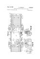
- FIGURE 1 is a somewhat diagrammatic front elevational view of a sliding bolster press according to the present invention.
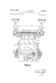
- FIGURE 2 is a plan sectional view indicated by line 22 on FIGURE 1 showing the bed of the press and the sliding bolsters with the sliding bolsters both in their outermost position.
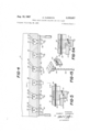
- FIGURE 3 is a diagrammatic vertical sectional View indicated by line 3-3 on FIGURE 1 showing in some detail the clamping arrangement for the upper portion of the die and also showing the drive to the bolster plate and the clamping of the bolster plate to the bed of thepress.
- FIGURE 4 is a transverse section indicated by line 4-4 'on FIGURE 3.
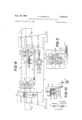
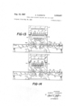
- FIGURE 5 is a sectional view indicated by line 5-5 on FIGURE 4 showing a clamp approaching the top plate of a die which is to be clamped to the press slide.
- FIGURE 5a is a view similar to FIGURE 5 which shows the clamp in the position it occupies when the plate is clamped to the slide.
- FIGURE 6 is a side elevational view of the press bed drawn at somewhat enlarged scale and showing the fluid operated clamp motor for clamping the bolsters to the bed and the connections of this motor with the clamping devices that engage the sliding bolsters.
- FIGURE 7 is a vertical sectional View indicated by line 77 on FIGURE 3 showing a clamping arm associated with the bolster clamping structure.
- FIGURE 8 is a sectional view indicated by line 8-8 on FIGURE 3 and showing other details in connection with the bolster clamping arrangement.
- FIGURE 9 is a fragmentary sectional view indicated by line 9--9 on FIGURE 2 and showing the aligning key means for effecting precise alignment of each bolster in the press when the bolster is set down in working position in the press.
- FIGURE 10 is a diagrammatic sectional view showing the adjustable connection of the slide to the connecting rods.
- FIGURE 11 is a diagrammatic View of an arrangement according to the present invention showing a die set loaded on the left hand bolster and ready to be moved into working position in the press.
- FIGURE 12 is a view like FIGURE 11 but shows the bolster together with the die set thereon moved into deflecting position in the press and with the press slide in the process of being adjusted to proper position for receiving the die set.
- FIGURE 13 is a view similar to FIGURES 11 and 12 but showing the bolster moved completely into the press into working position therein and clamped to the press bed.
- FIGURE 14 is a diagrammatic view similar to FIG- URES 11 thru 13 but shows the press slide lowered into position for clamping the slide to the top plate of the upper portion of the die set.
- FIGURE 15 is a somewhat diagrammatic perspective view showing one form which the pendulum detector arm can take.
- FIGURE 16 is a somewhat simplified diagrammatic representation of an electric control circuit for controlling the operation of the press and the actuation of the bolsters and the clamps and the measuring circuit forming a part of the present invention.
- the press comprises the usual bed and a head 12 with uprights 14 being provided between the head and the bed.
- Power means carried by the head is operable for reciprocating platen 16 which is carried in the usual manner on the press uprights.
- the particular drive means for the platen is not shown, but it will be understood to comprise a reversible motor connected with a crank shaft having connecting rod means leading to the platen.
- the connecting rod means are so arranged that the effective length thereof can be adjusted thereby to change the region of movement of the platen. This can be done by forming the connecting rod means of portions threaded together or by having the connecting rod means terminate in a screw that is threaded into nuts carried by the platen. By rotating the nuts, the platen can be raised or lowered for any given position of the driving crankshaft. The exact manner in which this is done will be described hereinafter.
- the press bed 10 is adapted for receiving bolsters, one of which is indicated at 18 in FIGURE 1.
- bolsters one of which is indicated at 18 in FIGURE 1.
- FIGURE 2 it will be observed that in addition to bolster 18 there is a second bolster 20 and that each of these bolsters is movable into and out of the press from the side thereof.
- Bolster 18, when moved out of the press is received on a support platform 22, whereas bolster 20 when it is moved out of the press is received on a supporting platform 24.
- Each bolster is provided with wheels 26 on the opposite side which run in tracks 28 formed in the platforms above referred to so that the bolsters will move in a predetermined path into and out of the press.
- the press bed similarly is provided with tracks 30 which form a continuation of tracks 28 so that the bolsters are guided throughout their movement into and out of working position in the press and can be moved relatively easily.
- each is provided on the bottom side thereof with a slot 32 in the side of which is mounted a long rack 34.
- This rack 34 meshes with a pinion 36 mounted on the output shaft of a speed reducer 38, the input shaft of which is driven by a motor 40.
- a drive unit for each of the bolsters so that they are operable independently of each other.
- the press bed includes vertically movable track sections on which the rollers 26 are disposed when the bolster is in working position. These movable track sections will be seen at 42 in FIGURES 3, 7 and 8. These sections are normally flush with the remainder of the guiding track portions and are moved downwardly when the bolster is in position thereby to lower the bolster to the press bed whereby the bolster is firmly supported by the press bed.
- FIGURES l-3 and 6-8 The mechanism for moving the track sections vertically will be seen in FIGURES l-3 and 6-8, and particularly in FIGURES 3, 7 and 8.
- This mechanism comprises an angular arm 44 pivoted adjacent each movable track section and having a portion 46 connected by pivot means 48 with the pertaining track section.
- Each arm has another portion 50, which other portions are interconnected by an adjustable drag link 52 so that the arms will move in unison.
- One of the arms has a projecting portion 54 connected to the ram of a double acting fluid motor 56.
- the motor When the motor is actuated in one direction, it elevates the track sections and supports them so that they form roller receiving surfaces flush with the remainder of the track sections, whereas when the motor is actuated in its other direction, the track sections are moved to their lowered position to lower the bolster to the bed.
- each arm 44 is fixed to a shaft 58, and these shafts extend completely through the bed and have fixed to their other ends corresponding arms 44 for actuating corresponding track sections at the opposite side of the bed.
- These other arms 44 are also connected by an adjustable drag link 52 so that all of the track sections are fixed together and will operate in unison.
- each movable track section is a clamping arrangement for clamping the bolster in its lowered position.
- These clamping portions comprise the hook elements 60 formed on the movable track sections and defining a groove for receiving the projections 62 formed on the members 64 that are secured to the sides of the bolsters and support the outer ends of the axles of rollers 26.
- the projecting portions 62 are located in the grooves defined by the hooks 60 so that when the track sections are moved, the hooks 60 clampingly engage the projecting portions 62 and lock the bolster to the bed.
- FIGURE 3 To demonstrate the lowering and clamping action referred to above, in FIGURE 3 at the left side, the track section and the bolster are illustrated in elevated position, whereas at the right side of this figure, the track section and bolster are illustrated in lowered position with the aforementioned clamping action taking place.
- Each of the track sections is vertically slidable in a space indicated at 66 in FIGURES 7 and 8, and this space is availed of for receiving the adjacent roller 26, as will best be seen in FIGURE 8, and this provides a sort of rest for the roller which assists in locating the roller and thereby for locating the bolster so that the operation of lowering the track sections and clamping the bolster in place will also serve to effect location of the bolster in the bed.
- each bolster has formed on the bed a hardened plug-like key 72 pertaining to one of the locator rings.
- each key 72 is tapered at an angle of say 30", so that slight misalignment of the keys and rings will be compensated for when the bolster sets down on the bed, and it will be guided into exact position on the bed when it is set down and clamped thereto.
- the press platen 16 is provided on its underneath side with a plurality of laterally extending T-shaped grooves These grooves are availed of for slidably receiving support blocks 82, which form portions of a clamping arrangement for clamping the upper portion of a die set to the press platen.
- Each support block 82 is connected to a pertaining screw 84 that extends from the outside face of the platen to the region of the center thereof where it is rotatably received in a support block 86- fixed to the platen.
- each screw 84 is connected through a self-locking worm drive 88 with a pneumatic torque motor 90, or similar source of rotating power such as an electric motor.
- the torque motors 90 can therefore be availed of for reversibly driving screws 84, which will cause blocks 82 to move toward and away from the center of the press platen.
- the self-locking worm drive 88 pertaining to each screw will lock it in its adjusted position when the pertaining block through motor 90 is de-energized.
- Each support block 82 comprises a dependent portion 92 formed with a recess opening toward the center of the platen and at its bottom having a wall portion inclined upwardly toward the outside of the press and formed to define a dove tail guide way 94.
- a clamp block 96 mounted on each dove tail guide way is a clamp block 96 which has its upper face formed in two horizontal steps, the lower one of which .six of the aforementioned support blocks 82 and clamp blocks 96 pertaining thereto on each side of the press, and
- the die sets are moved into working position in the press by movement of the bolster on which the die set is mounted into working position,
- the platen is automatically adjusted to sucha height that movement of the aforementioned clamping device inwardly toward the center of the platen will bring the pertaining clamp blocks into engagement with the side edges of the plate on the top of the upper die set and because of the inclined surfaces supporting the clamp blocks, the clamp blocks will move upwardly and clamp the aforementioned plate tightly to the press platen.
- the aforementioned selflocking worm drives will hold the clamping device in position.
- the clamping devices can be operated in groups so that for clamping small die sets in the press, only as many clamping devices as are necessary may be operated.
- This type of clamp allows for a range of sizes of both left to right and front to back dies.
- Other die clamps on the market do not allow for this but must have a die adapter plate of the same size for every die used in the press.
- An important feature of the present invention is to The found in conection with the automatic adjustment of the press platen to the proper height for receiving the die set therein. The particular manner .in which this is accomplished will be explained in detail in connection with the 1 electrical control circuit for the press, but reference to FIGURES 11 thru 14 will serve to indicate in general what takes place.
- FIGURES 11 thru 14 will show what takes place in the mounting of a die set in a press according to this invention.
- the left hand bolster 18 is provided with a die set generally indicated at 104 and illustrating i which the slide would occupy at the bottom of its stroke.
- FIGURE 12 shows that bolster 18 has been moved toward the center of the press until the center of the die set is about direct-1y beneath the pendulum detector or measuring arm 116 pivotally suspended at 118 at the top of the side opening of the press frame. This detector arm is deflected by the die set to an angle that corresponds to the height of the die set.
- the deflection of the measuring arm together with the actuation of the limit switch LDS which is engaged by cam 18a on the bolster 18 in its FIGURE 12 position makes the measuring system eifective and this will produce movement of the press slide in the proper position to bring about adjustment of the lowermost position thereof for receiving the die set.
- the slide is adjusted upwardly as indicated by arrow 119.
- the slide adjusts upwardly to a position where its lowermost position when the slide is at the bottom of its pressing stroke will receive the die set, the adjustment is terminated automatically, and the bolster can then move into working position, and is automatically clamped to the bed.
- FIGURE 13 shows the bolster 18 moved into working position and with the bolster clamped tight against the press bottom by the clamps previously referred to and which clamps are formed on the movable track sections 42.
- FIGURE 15 The nature of the particular detector arm referred to above will be better seen in FIGURE 15 wherein the arm 116 will be seen to be associated with a resistor element 130 by way of a movable arm 132.
- This arm moves along the resistor element as the pivot type detector arm 116 is arms, what occurs is that a reversible electric motor 120 (FIGURE 10) operates through a drive train 122 to actuate a nut 124 threadedly engaging a screw 126 pinned by a pin 128 to the lower end of connecting rod 131, the upper end of which is connected to a throw of the drive crankshaft of the press.
- a reversible electric motor 120 (FIGURE 10) operates through a drive train 122 to actuate a nut 124 threadedly engaging a screw 126 pinned by a pin 128 to the lower end of connecting rod 131, the upper end of which is connected to a throw of the drive crankshaft of the press.
- Nut 124 is clamped in the platen or slide 16 by clamp means 133 so that, as the nut rotates, the effective length of the pertaining connecting rod is adjusted.
- the connecting rods 131 there are at least two of the connecting rods 131, and each will have a screw and nut associated therewith.
- FIGURE 16 will show how the automatic operation of the press is carried out.
- FIGURE 16 the power lines are indicated at L1 and L2, and connected therebetween is the reversible motor 134 connected for driving crankshaft 136 that causes reciprocation of the slide 16 in the press frame.
- Motor 134 is controlled in its forward direction when the press is operating normally by relay R1, which is adapted for being energized by closing of the switch 137.
- the relay can be deenergized by opening stop switch 138.
- the cycle of the relay according to any predetermined pattern or schedule can be accomplished by a control arrangement 140 of conventional design which can provide for single cycle operation of the press or manual operation thereof or automatic or any other manner desired.
- Motor 134 is also adapted for being controlled in its forward direction by switch 142 which will cause the motor to run in the forward direction until limit switch LS2 is opened by the crankshaft at the uppermost limit of its travel.
- a switch 144 can be employed for running motor 134 in the reverse direction, and the motor will run in this direction until the slide reaches the bottom of its stroke when the crankshaft opens limit switch LS3 and stops motor 134.
- each bolster has associated therewith its own individual driving motor.
- Motor 40 pertains to the left hand bolster 18, while the motor 41 pertains to the right hand bolster 20.
- Each of these motors is reversible for selectively driving the bolster into or out of the press.
- Relay R2 For controlling bolster motor 40, there is a relay R2 which, upon energization by closing switch 150, will cause the bolster motor 40 to run in a direction to move bolster 18 toward the center of the press.
- Relay R2 has a holding circuit extending through limit switch LBI positioned for being opened by bolster 18 when it is in working position, so that the relay R2 will automatically be deenergized when bolster 18 reaches working position in the press.
- Movement of the left hand bolster outwardly is accomplished by energization of relay R3 which can be energized by closing of switch 154.
- the holding circuit for the coil of relay R3 is completed through a blade of limit switch LBO, which is positioned to be actuated into open position by the left hand bolster in its outer position.
- the right hand bolster 20 has an arrangement for reversibly energizing its drive motor 41 which is identical with that for bolster 18.
- the arrangement for bolster 20 includes the bolster in relay R4 energizable by switch 156 :and having limit switch RBI in its holding circuit.
- the right hand bolster out relay is R5 which is energized by switch 158 and with a limit switch RBO in the holding circuit.
- switches which will be seen in FIGURE 11 are actuated during inward movement of the pertaining bolster by respective cams 18a and 20a when the pertaining bolster reaches detecting position, but are passed idly by the said cams of the bolsters when they are moving outwardly from the press. It would also be possible to make these switches ineffective during outward movement of the bolsters by arranging normally closed contacts of relays R3 and R5 in the circuit to timer T. Closure of either of limit switches LDS or RDS will complete a circuit to a timer T.
- a blade T1 When the timer is energized, a blade T1 closes and completes a circuit to the coil of a relay R6, which closes its blade 160 to complete a circuit to a bridge circuit 162 which forms the measuring device for detecting the die height. Also blades 161 and 163 in circuit with motors 40 and 41 open and the motor which is running will come to a halt.
- Bridge circuit 162 has in one of its legs thereof the resistances 130L and 130R pertaining to the detector arms 116L for the left hand side of the press and 116R for the right hand side of the press, respectively.
- the resistances 130R and 130L are arranged for being made selectively effective by including in circuit at 130R a normally open blade of relay R2, and by including in circuit with resistance 138L normally open blade of relay R4. In this manner only, the adjustable resistor pertaining to the side of the press into which a bolster is being moved will be effective.
- a resistance 164 that is provided with an adjustable slide contact 166 that is connected to the slide adjusting motor for being adjusted thereby.
- any condition of unbalance established in the bridge circuit 162 by deflection of one or the other of the detector arms 116L or 116R will be reflected in a voltage difference across the bridge terminals, which can be utilized for actuating one or the other of relays R7 or R7.
- R7 will be energized for a condition of unbalance in one direction, indicating, for example, a die height above a predetermined amount, whereas R7 will be energized to indicate a die height below a predetermined amount.
- Relay R7 when energized closes its blade 168 and energizes slide motor 120 in a direction to cause the slide to move upwardly relative to the crankshaft.
- Relay R7 when energized, closes its blade 170, and this will cause slide motor 120 to run in a direction to adjust the slide downwardly relative to the crankshaft.
- Relay R7 has another normally closed blade 172 which is in series with a second normally closed blade 174 of relay R7. These blades are in circuit with a blade T2 of timer T and the coil of a relay R8. Timer blade T2 is arranged to close some time after the closing of the aforementioned time plate T1 so that, after the energizing circuit is made effective, timer blade T2 will close. But at this time, lif an adjusting cycle is taking place, closing of blade T2 will be without effect.
- both of relays R7 and R7 will be de-energized, and this will complete :a circuit through timer blade T2 to the coil of relay R8, causing this relay to open and its blade 176 to open, which is in circuit with the coil of relay R6.
- This will deenergize relay R6, which will close blades 1'61 and 163, which will again energize the bolster motor of the bolster that is moving into the press, whereupon the bolster will continue toward the center of the press.
- timer T will be de-ener gized and its pertaining blades will open.
- Solenoid S1 is connected for being energized by a circuit which passes through a normally closed blade 180 of the right hand bolster out switch 158 and a normally closed blade 182 of the left hand bolster out switch 154. From blade 182 the circuit extends to a contact 184 which is closed by switch LBI when the left hand bolster is completely in. From a point between blades 180 and 182 there is a connection to a second contact 186 of limit switch RBI that is closed when the right hand bolster is completely in.
- either bolster can be selectively moved into or out of the press and will be automatically clamped to the press bed when it reaches working position, and, also, each bolster will stop in an intermediate position when moved into the press and an automatic detection and measuring and slide adjusting operation will take place at the completion of which the bolster will continue its movement into working position in the press.
- the crankshaft 136 is operated to its downstroke position, as by operation of switch 144 and, on account of the adjustment of the slide during the aforementioned detection operation, the slide will be positioned close to the top plate of the upper part of the die set and will either bein position for clamping to the slide, or, at the most, a minor adjustment of the slide will be necessary to bring it into the proper position for attaching the upper part of the die set thereto.
- the manual switches 190 and 192 can be availed of for reversibly energizing motor 120.
- the clamping operation can now be carried out. This is done by actuating the clamp motors 90 to move the clamps inwardly to engage the edges of the top plate of the upper part of the die set. Inasmuch as die sets will vary in size, an arrangement is provided for actuating only the number of clamps that are required to hold the die set in place.
- a selector switch 200 which is movable from an oif position into any of three other positions, in the first of which four of the clamp motors 90 can be made effective, in the second of which eight of the clamp motors be made effective, and in the third of which twelve of the clamp motors can be made effective.
- a selector switch 200 which is movable from an oif position into any of three other positions, in the first of which four of the clamp motors 90 can be made effective, in the second of which eight of the clamp motors be made effective, and in the third of which twelve of the clamp motors can be made effective.
- the solenoids pertaining to the valves that produce outward movement may all be connected in parallel so that all of the clamps will move outward simultaneously.
- the motors 90 are pneumatically operated stall motors and can come to a halt when energized without there being any damage to the motor or the parts which it is driving.
- the clamping is elfected by adjusting switch 200 to the desired position and then closing a switch 202 which completes an energizing circuit to an air valve control solenoid 204 which will initiate a supply of air for the valves of the clamping motors.
- Switch 206 is then closed and this will effect energization of the ones of the solenoids which will produce inward movement of the clamps that are selected by the switch 200.
- the selected clamps will then move inwardly and engage the edges of the top plate of the die, as will be seen in FIGURE 5.
- the clamp blocks 96 ride up their inclines and pull the aforementioned top plate tightly against the surface of the slide.
- the clamping of the top plate is then made secure by closing a switch 208 which energizes the timer TC.
- This timer has blades TC1 and TC2 which operate simultaneously and which, upon energization of the switch 208 in the slide, will de-energize the clamp in solenoids and energize the clamp out solenoids.
- the in solenoids are under the control of blade TC1 and are indicated at 210, and the out solenoids are indicated at 212.
- timer TC has a third blade TC3 which, following the aforementioned action of retracting and then advancing the clamp blocks, opens the circuit leading to the air valve solenoid 204 and closes a circuit to a motor 214.
- Motor 214 drives a cam 216 which periodically closes a switch 218 to effect energization of the valve solenoid 204 on a cyclic basis.
- This arrangement there is a periodic supply of air under pressure to the air motors to set the clamps tightly in the event that any thereof have loosened, and immediately after this the air is again cut off until switch 218 is closed.
- This provides for periodic checking of the tightness of the clamps, and requires little power, and represents an advantageous safety feature in connection with the automatic clamping arrangement of the present invention.
- the present invention thus provides for a simple rapid I labor-saving arrangement for changing dies in a press
- the new die to be put into the press is secured to the bolster plate which is out while the press is still Working and, when the new die is to be put into the press, the press slide is moved to its down stroke position, the old die is unclamped by operation of the clamp motors by closing switch 207, the platen is then moved to its up stroke position, the bolster that is in the press is then moved out of the press, and the bolster that is out of the press is then moved toward the center of the press.
- the bolster moving into the press will halt in an intermediate position while a measuring and slide adjusting operation takes place. When this adjusting operation is completed, the bolster moves on into working position and the press operator can then move the slide to down stroke position, make any minor adjustments necessary to the slide position, clamp the new die set in place to the press slide, and the press is ready to be placed in operation.
Description
Aug. 1967 A. CLEMENTS 3,335,657
PRESS WITH SLIDING BOLSTER AND DIE CLAMP Original Filed May 26, 1965 8 Sheets-Sheet 1 F I6, INVY'ENTOR.
HLBERT CLEMENTS BY W HTTORNEYS Aug. 15, 1967 A. CLEMENTS PRESS WITH SLIDING BOLSTER AND DIE CLAMP 8 Sheets-Sheet 2 Original Filed May 26, 1965 INVENTOR I ALBERT CLEMENTS W Z Wfw Original Filed May 26, 1965 Aug. 15, 1967 PRESS WITH SLIDING BOLSTER AND DIE CLAMP 8 Sheets-Sheet 5 INVENTOR. ALBERT CLEMENTS BY W TTORNEYS A. CLEMENTS 3,335,657
Aug. 15, 1967 (:LEMENTS 3,335,657
PRESS WITH SLIDING BOLSTER AND DIE CLAMP Original Filed May 26, 1965 8 Sheets-Sheet 4 FIG'S 5 20 5 a w xx -xx 96 n2 INVENTOR. HLBEFPT CLEMENTS E IZY HTTO 'P Aug. 15, 1967 A. CLEMENTS 3,335,657
PRESS WITH SLIDING BOLSTER AND DIE CLAMP Original Filed May 26, 1965 8 Sheets-Sheet 5 FIG-6 INVENTOR.
HLBEFPT CLEMEN T5 BYW4W 1967 A. CLEMENTS 3,335,657
PRESS WITH SLIDING BOLSTER AND DIE CLAMP Original Filed May 26, 1965 8 Sheets-Sheet 6 INVENTORR o ALBERT CLEMEN 7'5 BY W HTTORNE Y5 A. CLEMENTS Aug. 15, 1967 PRESS WITH SLIDING BOLSTER AND DIE CLAMP 8 Sheets-Sheet 7 Original Filed May 26, 1965 FIG-I4 INVENTOR. ALBERT CLEMENTS W i HTTORNEYS Aug. 15, 1967 A. CLEMENTS Original Filed May 26, 1965 PRESS WITH SLIDING BOLSTER AND DIE CLAMP 8 Sheets-Sheet 8 m 5 f 1, "i;
' 1 FIG-l6 INVENTOR. HLBERT CLEMEN S United States Patent Public 2 Claims. (Cl. 100-35) This application is a continuation application of my copending application filed May 26, 1965, entitled, Press with Sliding Bolster and Die Clamp," Ser. No. 458,992;
which copending application is a divisional application of U.S. Patent No. 3,225,686 entitled, Press with Sliding Bolster and Die Clamp, filed Aug. 30, 1963, Ser. No. 305,693.
This invention relates to a method of adjusting a press slide automatically.
Sliding bolster presses are known in the art and are employed where, for one reason or another, it is desirable completely to withdraw from working position in a press, at least the lower part of the die set after a working stroke of the press. This might come about on account of the necessity of removing work members from the die or for other reasons. Also, sliding bolster presses are employed where die changes are to be made because the bolster can readily be withdrawn from the press with the entire die thereon and this facilitates the work of removing dies from the press and installing new dies in the press.
Sliding bolsters have also been used in die spotting presses for readily removing or changing dies.
A particular problem that has always existed in connection with presses of this nature has been the operation or positioning and clamping of dies in place on the bolster, and another particular problem has been initial positioning of the press platen and the clamping of the upper die portion to the press platen.
The present invention proposes an arrangement for minimizing the time and eifort required to install dies in a press and to clamp the upper die part to the press platen, and it is further proposed by the present invention to provide an improved sliding bolster arrangement for the press.
In general, the press according to the present invention is designed around what might considered to be a conventional press frame consisting of a bed, a head, uprights extending between the bed and the head and a press platen slidably guided on the uprights. According to the present invention at least one, and preferably two bolsters, are provided which are slidably guided from working position on the press bed out of the press bed to supporting means adjacent the press frame. Each bolster can thus be provided with a die set externally of the press which can then be moved into working position in the press and the upper portion of the die set attached to the press platen. The bolsters may slide front to back or left to right through openings in the uprights.
According to this invention, the connecting of the upper portion of the die set to the press platen is greatly facilitated by providing a detector arrangement that detects the height of the die set on the bolster and adjusts the press platen in conformity to the height of the die set whereby manual adjustment of the press platen into position to clamp the upper portion of the die set thereto is eliminated or, at least, greatly reduced.
The present invention also embodies power driven clamping means for clamping the upper die set to the platen so that manual operations in connection with secur- 3,335,657 Patented Aug. 15, 1967 ice ing the upper portion of the die set to the platen are eliminated.
From the foregoing it will be evident that a primary object of the present invention is the provision of a greatly improved sliding bolsterpress having automatic die clamping means associated with the platen.
A still further object of the present invention is the provision of an improved sliding bolster type press having automatic clamping means carried by the platen and a detector for detecting the height of the die set to be clamped on the press and controlling the positioning of the press platen.
Still another object of this invention is the provision of a sliding bolster press having detector means for detecting the height of the die set and adjusting the platen in. conformity therewith, and including control means for the sliding bolster so that it will automatically halt in its movement in the press during the aforementioned detecting operation.
The foregoing objects as well as still other objects and advantages of the present invention will become more apparent upon reference to the following specification taken in connection with the accompanying drawings in which:
FIGURE 1 is a somewhat diagrammatic front elevational view of a sliding bolster press according to the present invention.
FIGURE 2 is a plan sectional view indicated by line 22 on FIGURE 1 showing the bed of the press and the sliding bolsters with the sliding bolsters both in their outermost position. FIGURE 3 is a diagrammatic vertical sectional View indicated by line 3-3 on FIGURE 1 showing in some detail the clamping arrangement for the upper portion of the die and also showing the drive to the bolster plate and the clamping of the bolster plate to the bed of thepress. FIGURE 4 is a transverse section indicated by line 4-4 'on FIGURE 3.
FIGURE 5 is a sectional view indicated by line 5-5 on FIGURE 4 showing a clamp approaching the top plate of a die which is to be clamped to the press slide.
FIGURE 5a is a view similar to FIGURE 5 which shows the clamp in the position it occupies when the plate is clamped to the slide. FIGURE 6 is a side elevational view of the press bed drawn at somewhat enlarged scale and showing the fluid operated clamp motor for clamping the bolsters to the bed and the connections of this motor with the clamping devices that engage the sliding bolsters.
. FIGURE 7 is a vertical sectional View indicated by line 77 on FIGURE 3 showing a clamping arm associated with the bolster clamping structure.
.FIGURE 8 is a sectional view indicated by line 8-8 on FIGURE 3 and showing other details in connection with the bolster clamping arrangement.
FIGURE 9 is a fragmentary sectional view indicated by line 9--9 on FIGURE 2 and showing the aligning key means for effecting precise alignment of each bolster in the press when the bolster is set down in working position in the press.
FIGURE 10 is a diagrammatic sectional view showing the adjustable connection of the slide to the connecting rods.
FIGURE 11 is a diagrammatic View of an arrangement according to the present invention showing a die set loaded on the left hand bolster and ready to be moved into working position in the press.
FIGURE 12 is a view like FIGURE 11 but shows the bolster together with the die set thereon moved into deflecting position in the press and with the press slide in the process of being adjusted to proper position for receiving the die set.
FIGURE 13 is a view similar to FIGURES 11 and 12 but showing the bolster moved completely into the press into working position therein and clamped to the press bed. FIGURE 14 is a diagrammatic view similar to FIG- URES 11 thru 13 but shows the press slide lowered into position for clamping the slide to the top plate of the upper portion of the die set.
FIGURE 15 is a somewhat diagrammatic perspective view showing one form which the pendulum detector arm can take.
FIGURE 16 is a somewhat simplified diagrammatic representation of an electric control circuit for controlling the operation of the press and the actuation of the bolsters and the clamps and the measuring circuit forming a part of the present invention.
Referring to the drawings somewhat more in detail, the press according to the present invention comprises the usual bed and a head 12 with uprights 14 being provided between the head and the bed. Power means carried by the head is operable for reciprocating platen 16 which is carried in the usual manner on the press uprights. The particular drive means for the platen is not shown, but it will be understood to comprise a reversible motor connected with a crank shaft having connecting rod means leading to the platen.
The connecting rod means are so arranged that the effective length thereof can be adjusted thereby to change the region of movement of the platen. This can be done by forming the connecting rod means of portions threaded together or by having the connecting rod means terminate in a screw that is threaded into nuts carried by the platen. By rotating the nuts, the platen can be raised or lowered for any given position of the driving crankshaft. The exact manner in which this is done will be described hereinafter.
The press bed 10 is adapted for receiving bolsters, one of which is indicated at 18 in FIGURE 1. In FIGURE 2 it will be observed that in addition to bolster 18 there is a second bolster 20 and that each of these bolsters is movable into and out of the press from the side thereof. Bolster 18, when moved out of the press is received on a support platform 22, whereas bolster 20 when it is moved out of the press is received on a supporting platform 24.
Each bolster is provided with wheels 26 on the opposite side which run in tracks 28 formed in the platforms above referred to so that the bolsters will move in a predetermined path into and out of the press. The press bed similarly is provided with tracks 30 which form a continuation of tracks 28 so that the bolsters are guided throughout their movement into and out of working position in the press and can be moved relatively easily.
For moving the bolsters, each is provided on the bottom side thereof with a slot 32 in the side of which is mounted a long rack 34. This rack 34 meshes with a pinion 36 mounted on the output shaft of a speed reducer 38, the input shaft of which is driven by a motor 40. As will be seen in FIGURE 2, there is a drive unit for each of the bolsters so that they are operable independently of each other.
During the time that the bolsters are moving into and out of the press, they are supported on their respective rollers and are otherwise in spaced relation to the supporting platform and the press bed. When the bolsters reach working position in the press bed, however, it is desirable for them to be set down on the bed as illustrated in FIG- URE 3 so that a firm bearing of the bolster on the press bed will be had in order to transmit pressing forces directly to the press bed. For permitting the bolsters to set down on the press bed, the press bed includes vertically movable track sections on which the rollers 26 are disposed when the bolster is in working position. These movable track sections will be seen at 42 in FIGURES 3, 7 and 8. These sections are normally flush with the remainder of the guiding track portions and are moved downwardly when the bolster is in position thereby to lower the bolster to the press bed whereby the bolster is firmly supported by the press bed.
The mechanism for moving the track sections vertically will be seen in FIGURES l-3 and 6-8, and particularly in FIGURES 3, 7 and 8. This mechanism comprises an angular arm 44 pivoted adjacent each movable track section and having a portion 46 connected by pivot means 48 with the pertaining track section. Each arm has another portion 50, which other portions are interconnected by an adjustable drag link 52 so that the arms will move in unison. One of the arms has a projecting portion 54 connected to the ram of a double acting fluid motor 56. When the motor is actuated in one direction, it elevates the track sections and supports them so that they form roller receiving surfaces flush with the remainder of the track sections, whereas when the motor is actuated in its other direction, the track sections are moved to their lowered position to lower the bolster to the bed.
As will be seen in FIGURE 6, each arm 44 is fixed to a shaft 58, and these shafts extend completely through the bed and have fixed to their other ends corresponding arms 44 for actuating corresponding track sections at the opposite side of the bed. These other arms 44 are also connected by an adjustable drag link 52 so that all of the track sections are fixed together and will operate in unison.
Incorporated in each movable track section is a clamping arrangement for clamping the bolster in its lowered position. These clamping portions comprise the hook elements 60 formed on the movable track sections and defining a groove for receiving the projections 62 formed on the members 64 that are secured to the sides of the bolsters and support the outer ends of the axles of rollers 26. When the bolster is in position, the projecting portions 62 are located in the grooves defined by the hooks 60 so that when the track sections are moved, the hooks 60 clampingly engage the projecting portions 62 and lock the bolster to the bed.
To demonstrate the lowering and clamping action referred to above, in FIGURE 3 at the left side, the track section and the bolster are illustrated in elevated position, whereas at the right side of this figure, the track section and bolster are illustrated in lowered position with the aforementioned clamping action taking place.
Each of the track sections is vertically slidable in a space indicated at 66 in FIGURES 7 and 8, and this space is availed of for receiving the adjacent roller 26, as will best be seen in FIGURE 8, and this provides a sort of rest for the roller which assists in locating the roller and thereby for locating the bolster so that the operation of lowering the track sections and clamping the bolster in place will also serve to effect location of the bolster in the bed.
The actual precision locating of the bolster in the press, however, is accomplished by the provision of hardened keys or locator rings 70 set into the press bed, as are indicated generally in FIGURE 2 and in section in FIG- URE 9. For cooperation with these hardened keys 70, each bolster has formed on the bed a hardened plug-like key 72 pertaining to one of the locator rings. In FIG- URE 9 it will be noted that each key 72 is tapered at an angle of say 30", so that slight misalignment of the keys and rings will be compensated for when the bolster sets down on the bed, and it will be guided into exact position on the bed when it is set down and clamped thereto.
As will be seen in FIGURES 3, 4 and 5, the press platen 16 is provided on its underneath side with a plurality of laterally extending T-shaped grooves These grooves are availed of for slidably receiving support blocks 82, which form portions of a clamping arrangement for clamping the upper portion of a die set to the press platen.
Each support block 82 is connected to a pertaining screw 84 that extends from the outside face of the platen to the region of the center thereof where it is rotatably received in a support block 86- fixed to the platen. At its extreme outer end, each screw 84 is connected through a self-locking worm drive 88 with a pneumatic torque motor 90, or similar source of rotating power such as an electric motor. The torque motors 90 can therefore be availed of for reversibly driving screws 84, which will cause blocks 82 to move toward and away from the center of the press platen. The self-locking worm drive 88 pertaining to each screw will lock it in its adjusted position when the pertaining block through motor 90 is de-energized.
Each support block 82 comprises a dependent portion 92 formed with a recess opening toward the center of the platen and at its bottom having a wall portion inclined upwardly toward the outside of the press and formed to define a dove tail guide way 94. Mounted on each dove tail guide way is a clamp block 96 which has its upper face formed in two horizontal steps, the lower one of which .six of the aforementioned support blocks 82 and clamp blocks 96 pertaining thereto on each side of the press, and
these are availed of for clamping the upper portion of the die sets of various sizes to the press platen. As will be explained more fully hereinafter, the die sets are moved into working position in the press by movement of the bolster on which the die set is mounted into working position,
and the platen is automatically adjusted to sucha height that movement of the aforementioned clamping device inwardly toward the center of the platen will bring the pertaining clamp blocks into engagement with the side edges of the plate on the top of the upper die set and because of the inclined surfaces supporting the clamp blocks, the clamp blocks will move upwardly and clamp the aforementioned plate tightly to the press platen. The aforementioned selflocking worm drives will hold the clamping device in position.
Further, in order to accommodate the press to die sets of different sizes, the clamping devices can be operated in groups so that for clamping small die sets in the press, only as many clamping devices as are necessary may be operated. This type of clamp allows for a range of sizes of both left to right and front to back dies. Other die clamps on the market do not allow for this but must have a die adapter plate of the same size for every die used in the press.
An important feature of the present invention is to The found in conection with the automatic adjustment of the press platen to the proper height for receiving the die set therein. The particular manner .in which this is accomplished will be explained in detail in connection with the 1 electrical control circuit for the press, but reference to FIGURES 11 thru 14 will serve to indicate in general what takes place.
Reference to FIGURES 11 thru 14 will show what takes place in the mounting of a die set in a press according to this invention.
In FIGURE 11 the left hand bolster 18 is provided with a die set generally indicated at 104 and illustrating i which the slide would occupy at the bottom of its stroke.
It will be noted that this lowermost position ofthe slide is too low for receiving the die set.
FIGURE 12 shows that bolster 18 has been moved toward the center of the press until the center of the die set is about direct-1y beneath the pendulum detector or measuring arm 116 pivotally suspended at 118 at the top of the side opening of the press frame. This detector arm is deflected by the die set to an angle that corresponds to the height of the die set.
By means of a measuring circuit to be described hereinafter, the deflection of the measuring arm together with the actuation of the limit switch LDS which is engaged by cam 18a on the bolster 18 in its FIGURE 12 position, makes the measuring system eifective and this will produce movement of the press slide in the proper position to bring about adjustment of the lowermost position thereof for receiving the die set. In the particular case illustrated, since the bottom position of the slide is too low for receiving the die set, the slide is adjusted upwardly as indicated by arrow 119. When the slide adjusts upwardly to a position where its lowermost position when the slide is at the bottom of its pressing stroke will receive the die set, the adjustment is terminated automatically, and the bolster can then move into working position, and is automatically clamped to the bed.
FIGURE 13 shows the bolster 18 moved into working position and with the bolster clamped tight against the press bottom by the clamps previously referred to and which clamps are formed on the movable track sections 42.
After the bolster 18 has reached working position in the press and the bolster is clamped to the press bottom, the press slide is moved to its bottom stroke position,
which position is illustrated in FIGURE 14, and thereafter the several clamps carried by the slide are actuated to clamp the top plate of the upper portion of the die set to the press slide.
The nature of the particular detector arm referred to above will be better seen in FIGURE 15 wherein the arm 116 will be seen to be associated with a resistor element 130 by way of a movable arm 132. This arm moves along the resistor element as the pivot type detector arm 116 is arms, what occurs is that a reversible electric motor 120 (FIGURE 10) operates through a drive train 122 to actuate a nut 124 threadedly engaging a screw 126 pinned by a pin 128 to the lower end of connecting rod 131, the upper end of which is connected to a throw of the drive crankshaft of the press. Nut 124 is clamped in the platen or slide 16 by clamp means 133 so that, as the nut rotates, the effective length of the pertaining connecting rod is adjusted. Normally, there are at least two of the connecting rods 131, and each will have a screw and nut associated therewith.
Reference now to the FIGURE 16 will show how the automatic operation of the press is carried out.
In FIGURE 16 the power lines are indicated at L1 and L2, and connected therebetween is the reversible motor 134 connected for driving crankshaft 136 that causes reciprocation of the slide 16 in the press frame. Motor 134 is controlled in its forward direction when the press is operating normally by relay R1, which is adapted for being energized by closing of the switch 137. The relay can be deenergized by opening stop switch 138. The cycle of the relay according to any predetermined pattern or schedule can be accomplished by a control arrangement 140 of conventional design which can provide for single cycle operation of the press or manual operation thereof or automatic or any other manner desired.
Motor 134 is also adapted for being controlled in its forward direction by switch 142 which will cause the motor to run in the forward direction until limit switch LS2 is opened by the crankshaft at the uppermost limit of its travel. Similarly, a switch 144 can be employed for running motor 134 in the reverse direction, and the motor will run in this direction until the slide reaches the bottom of its stroke when the crankshaft opens limit switch LS3 and stops motor 134.
As has been mentioned before, each bolster has associated therewith its own individual driving motor. Motor 40 pertains to the left hand bolster 18, while the motor 41 pertains to the right hand bolster 20. Each of these motors is reversible for selectively driving the bolster into or out of the press.
For controlling bolster motor 40, there is a relay R2 which, upon energization by closing switch 150, will cause the bolster motor 40 to run in a direction to move bolster 18 toward the center of the press. Relay R2 has a holding circuit extending through limit switch LBI positioned for being opened by bolster 18 when it is in working position, so that the relay R2 will automatically be deenergized when bolster 18 reaches working position in the press.
Movement of the left hand bolster outwardly is accomplished by energization of relay R3 which can be energized by closing of switch 154. The holding circuit for the coil of relay R3 is completed through a blade of limit switch LBO, which is positioned to be actuated into open position by the left hand bolster in its outer position.
The right hand bolster 20 has an arrangement for reversibly energizing its drive motor 41 which is identical with that for bolster 18. The arrangement for bolster 20 includes the bolster in relay R4 energizable by switch 156 :and having limit switch RBI in its holding circuit. The right hand bolster out relay is R5 which is energized by switch 158 and with a limit switch RBO in the holding circuit.
In order to carry out the die height detecting operation, however, energization of either of the bolster in relays R2 or R4 will not be accompanied by complete inward movement of the pertaining bolster; but instead, the pertaining bolster will come to a halt in an intermediate detecting position with the detecting arm engaging the top of the die set. This is brought about by actuation of the pertaining one of limit switches LDS or RDS, the former pertaining to the left hand bolster and the latter pertaining to the right hand bolster.
These switches which will be seen in FIGURE 11 are actuated during inward movement of the pertaining bolster by respective cams 18a and 20a when the pertaining bolster reaches detecting position, but are passed idly by the said cams of the bolsters when they are moving outwardly from the press. It would also be possible to make these switches ineffective during outward movement of the bolsters by arranging normally closed contacts of relays R3 and R5 in the circuit to timer T. Closure of either of limit switches LDS or RDS will complete a circuit to a timer T.
When the timer is energized, a blade T1 closes and completes a circuit to the coil of a relay R6, which closes its blade 160 to complete a circuit to a bridge circuit 162 which forms the measuring device for detecting the die height. Also blades 161 and 163 in circuit with motors 40 and 41 open and the motor which is running will come to a halt. Bridge circuit 162 has in one of its legs thereof the resistances 130L and 130R pertaining to the detector arms 116L for the left hand side of the press and 116R for the right hand side of the press, respectively. The resistances 130R and 130L are arranged for being made selectively effective by including in circuit at 130R a normally open blade of relay R2, and by including in circuit with resistance 138L normally open blade of relay R4. In this manner only, the adjustable resistor pertaining to the side of the press into which a bolster is being moved will be effective.
In another leg of the bridge is a resistance 164 that is provided with an adjustable slide contact 166 that is connected to the slide adjusting motor for being adjusted thereby.
Any condition of unbalance established in the bridge circuit 162 by deflection of one or the other of the detector arms 116L or 116R will be reflected in a voltage difference across the bridge terminals, which can be utilized for actuating one or the other of relays R7 or R7. R7 will be energized for a condition of unbalance in one direction, indicating, for example, a die height above a predetermined amount, whereas R7 will be energized to indicate a die height below a predetermined amount. Relay R7 when energized closes its blade 168 and energizes slide motor 120 in a direction to cause the slide to move upwardly relative to the crankshaft. Relay R7, on the other hand, when energized, closes its blade 170, and this will cause slide motor 120 to run in a direction to adjust the slide downwardly relative to the crankshaft.
Relay R7 has another normally closed blade 172 which is in series with a second normally closed blade 174 of relay R7. These blades are in circuit with a blade T2 of timer T and the coil of a relay R8. Timer blade T2 is arranged to close some time after the closing of the aforementioned time plate T1 so that, after the energizing circuit is made effective, timer blade T2 will close. But at this time, lif an adjusting cycle is taking place, closing of blade T2 will be without effect. However, upon the adjusting operation being completed and a condition of balance being established in bridge circuit 162, both of relays R7 and R7 will be de-energized, and this will complete :a circuit through timer blade T2 to the coil of relay R8, causing this relay to open and its blade 176 to open, which is in circuit with the coil of relay R6. This will deenergize relay R6, which will close blades 1'61 and 163, which will again energize the bolster motor of the bolster that is moving into the press, whereupon the bolster will continue toward the center of the press.
As soon as the bolster runs off the one of limit switches LDS and RDS which is closed, timer T will be de-ener gized and its pertaining blades will open.
At this time the bolster is ready to be clamped to the bed, and the solenoid S1 pertaining to the valve 5611 connected to the bolster clamp is energized. Solenoid S1 is connected for being energized by a circuit which passes through a normally closed blade 180 of the right hand bolster out switch 158 and a normally closed blade 182 of the left hand bolster out switch 154. From blade 182 the circuit extends to a contact 184 which is closed by switch LBI when the left hand bolster is completely in. From a point between blades 180 and 182 there is a connection to a second contact 186 of limit switch RBI that is closed when the right hand bolster is completely in.
The movement of either bolster to working position in the press will thus cause energization of the clamp solenoid S1, whereas the depressing of either of the bolster out switches 154 and 158 will effect de-energization of the clamp solenoid S1 so that the bolster will be unclamped and can move out of the press. As soon as either bolster commences to move out of working position in the press, its pertaining switch LBI or RBI will drop closed and thereafter the clamp solenoid will remain deenergized.
In the manner described above, either bolster can be selectively moved into or out of the press and will be automatically clamped to the press bed when it reaches working position, and, also, each bolster will stop in an intermediate position when moved into the press and an automatic detection and measuring and slide adjusting operation will take place at the completion of which the bolster will continue its movement into working position in the press.
After the bolster carrying a die set has been moved into working position in the press, the crankshaft 136 is operated to its downstroke position, as by operation of switch 144 and, on account of the adjustment of the slide during the aforementioned detection operation, the slide will be positioned close to the top plate of the upper part of the die set and will either bein position for clamping to the slide, or, at the most, a minor adjustment of the slide will be necessary to bring it into the proper position for attaching the upper part of the die set thereto.
In connection with any manual adjustments necessary on the slide motor, the manual switches 190 and 192 can be availed of for reversibly energizing motor 120.
With the bolster carrying the die set now in working position in the press and clamped to the bed, and with the press slide moved to its down stroke position and, if necessary, adjusted to a position close to or even engaging the top plate of the upper die, the clamping operation can now be carried out. This is done by actuating the clamp motors 90 to move the clamps inwardly to engage the edges of the top plate of the upper part of the die set. Inasmuch as die sets will vary in size, an arrangement is provided for actuating only the number of clamps that are required to hold the die set in place.
This is done, as will be seen in FIGURE 16, by a selector switch 200 which is movable from an oif position into any of three other positions, in the first of which four of the clamp motors 90 can be made effective, in the second of which eight of the clamp motors be made effective, and in the third of which twelve of the clamp motors can be made effective. In the drawing it will be understood that there are reversing valves pertaining to the clamp motors and that these are double solenoid operated so that what the switch 200 controls is the groups of solenoids pertaining to the valves of the motors to be actuated and, specifically, the solenoids which produce inward movement of the clamp motors.
The solenoids pertaining to the valves that produce outward movement may all be connected in parallel so that all of the clamps will move outward simultaneously. As mentioned, the motors 90 are pneumatically operated stall motors and can come to a halt when energized without there being any damage to the motor or the parts which it is driving.
In the clamp circuit, the clamping is elfected by adjusting switch 200 to the desired position and then closing a switch 202 which completes an energizing circuit to an air valve control solenoid 204 which will initiate a supply of air for the valves of the clamping motors. Switch 206 is then closed and this will effect energization of the ones of the solenoids which will produce inward movement of the clamps that are selected by the switch 200. The selected clamps will then move inwardly and engage the edges of the top plate of the die, as will be seen in FIGURE 5. When the clamps are driven completely inwardly, the clamp blocks 96 ride up their inclines and pull the aforementioned top plate tightly against the surface of the slide.
According to the present invention, the clamping of the top plate is then made secure by closing a switch 208 which energizes the timer TC. This timer has blades TC1 and TC2 which operate simultaneously and which, upon energization of the switch 208 in the slide, will de-energize the clamp in solenoids and energize the clamp out solenoids. The in solenoids are under the control of blade TC1 and are indicated at 210, and the out solenoids are indicated at 212. This operation of the blades T C1 and TC2 will bring about a short retracting movement of the clamp, and thereafter blades TC1 and TCZ will cooperate to again de-energize the out solenoids and energize the in solenoids, and the clamps again will be driven against the top plate of the die set and the clamping of the die set to the press slide has thus been made certain.
The screws 84 will hold the clamp blocks in adjusted position so that there is no tendency for the top plate to come loose from the slide. However, in order to prevent any accidental loosening of the top plate from the slide, timer TC has a third blade TC3 which, following the aforementioned action of retracting and then advancing the clamp blocks, opens the circuit leading to the air valve solenoid 204 and closes a circuit to a motor 214.
Motor 214 drives a cam 216 which periodically closes a switch 218 to effect energization of the valve solenoid 204 on a cyclic basis. With this arrangement there is a periodic supply of air under pressure to the air motors to set the clamps tightly in the event that any thereof have loosened, and immediately after this the air is again cut off until switch 218 is closed. This provides for periodic checking of the tightness of the clamps, and requires little power, and represents an advantageous safety feature in connection with the automatic clamping arrangement of the present invention.
The present invention thus provides for a simple rapid I labor-saving arrangement for changing dies in a press,
and an arrangement which is particularly conserving of the press working time, because a minimum amount of press down time is required for changing dies. The new die to be put into the press is secured to the bolster plate which is out while the press is still Working and, when the new die is to be put into the press, the press slide is moved to its down stroke position, the old die is unclamped by operation of the clamp motors by closing switch 207, the platen is then moved to its up stroke position, the bolster that is in the press is then moved out of the press, and the bolster that is out of the press is then moved toward the center of the press. As explained before, the bolster moving into the press will halt in an intermediate position while a measuring and slide adjusting operation takes place. When this adjusting operation is completed, the bolster moves on into working position and the press operator can then move the slide to down stroke position, make any minor adjustments necessary to the slide position, clamp the new die set in place to the press slide, and the press is ready to be placed in operation.
All the foregoing steps can be carried out rapidly and conveniently so that not only is labor saved, but harmful accidents are avoided, which might damage expensive die sets or cause injury to personnel and the maximum working time of the press is available.
It will be understood that this invention is susceptible to modifications in order to adapt it to different usages and conditions; and accordingly, it is desired to comprehend such modifications within this invention as may fall within the scope of the appended claims.
I claim:
1. The method of adjusting the operative length of an adjustable connecting rod which operates a slide on a press in accordance with the height of a. die set mounted on a movable bolster in said press, comprising the steps of:
(a) mounting a die set on a movable bolster;
(b) moving the bolster and mounted die set toward its working position in the press;
(c) detecting the height of the die set relative to a reference level of the press at a predetermined intermediate point adjacent the working position in the movement of the bolster and die set toward its working position;
(d) adjusting the operative length of the connecting rod, and thereby the operative stroke of the slide, as a function of the detected height of the die set relative to such reference level;
(e) operating the slide to its stroke position;
(f) and connecting the operated slide to the upper portion of the die set.
2. The method of claim 1 and comprising the further steps of:
(a) stopping the bolster and die set prior to their reaching the Working position in the press;
(b) and detecting the height of the die set relative to the reference level While the bolster and die set are stopped.
References Cited UNITED STATES PATENTS 2,234,401 7/1943 Kimball 53 75 2,550,923 5/1951 Kay 53 75 10 2,313,793 1/1953 Deykin 100 257 Johansen et a1. 72--412 Heiberger et a1. 318-29 Keely et 211. Hill 100-53 X Georgeff 72414 Danly et al 72414 Munschaure et a1. 100-257 X BILLY J. WILHITE, Primary Examiner.
W. A. SCHEEL, Examiner.
Claims (1)
1. THE METHOD OF ADJUSTING THE OPERATIVE LENGTH OF AN ADJUSTABLE CONNECTING ROD WHICH OPERATES A SLIDE ON A PRESS IN ACCORDANCE WITH THE HEIGHT OF A DIE SET MOUNTED ON A MOVABLE BOLSTER IN SAID PRESS, COMPRISING THE STEPS OF: (A) MOUNTING A DIE SET ON A MOVABLE BOLSTER; (B) MOVING THE BOLSTER AND MOUNTED DIE SET TOWARD ITS WORKING POSITION IN THE PRESS; (C) DETECTING THE HEIGHT OF THE DIE SET RELATIVE TO A REFERENCE LEVEL OF THE PRESS AT A PREDETERMINED INTERMEDIATE POINT ADJACENT THE WORKING POSITION IN THE MOVEMENT OF THE BOLSTER AND DIE SET TOWARD ITS WORKING POSITION; (D) ADJUSTING THE OPERATIVE LENGTH OF THE CONNECTING ROD, AND THEREBY THE OPERATIVE STROKE OF THE SLIDE, AS A FUNCTION OF THE DETECTED HEIGHT OF THE DIE SET RELATIVE TO SUCH REFERENCE LEVEL; (E) OPERATING THE SLIDE TO ITS STROKE POSITION; (F) AND CONNECTING THE OPERATED SLIDE TO THE UPPER PORTION OF THE DIE SET.
Priority Applications (1)
| Application Number | Priority Date | Filing Date | Title |
|---|---|---|---|
| US553251A US3335657A (en) | 1966-05-26 | 1966-05-26 | Press with sliding bolster and die clamp |
Applications Claiming Priority (1)
| Application Number | Priority Date | Filing Date | Title |
|---|---|---|---|
| US553251A US3335657A (en) | 1966-05-26 | 1966-05-26 | Press with sliding bolster and die clamp |
Publications (1)
| Publication Number | Publication Date |
|---|---|
| US3335657A true US3335657A (en) | 1967-08-15 |
Family
ID=24208733
Family Applications (1)
| Application Number | Title | Priority Date | Filing Date |
|---|---|---|---|
| US553251A Expired - Lifetime US3335657A (en) | 1966-05-26 | 1966-05-26 | Press with sliding bolster and die clamp |
Country Status (1)
| Country | Link |
|---|---|
| US (1) | US3335657A (en) |
Cited By (4)
| Publication number | Priority date | Publication date | Assignee | Title |
|---|---|---|---|---|
| US4152978A (en) * | 1976-08-31 | 1979-05-08 | Amada Company, Ltd. | Methods and apparatus for changing dies in a press and stocking them |
| WO1980002250A1 (en) * | 1979-04-20 | 1980-10-30 | Mitsuishi Fukai Iron Works | Moulding machine for bricks or the like |
| DE3507912C1 (en) * | 1985-03-06 | 1986-11-13 | Maschinenfabrik Hilma Gmbh, 5912 Hilchenbach | Device for attaching an upper tool under the clamping surface of a press ram |
| US4790174A (en) * | 1986-05-30 | 1988-12-13 | Firma Maschinenfabrik Hilma Gmbh | Adjusting drive for insert tighteners of presses |
Citations (10)
| Publication number | Priority date | Publication date | Assignee | Title |
|---|---|---|---|---|
| US2234401A (en) * | 1938-08-22 | 1941-03-11 | Emil N Farkas | Binding and method of making |
| US2550928A (en) * | 1943-06-09 | 1951-05-01 | Rose Brothers Ltd | Article controlled adjustment for packaging apparatus |
| US2818798A (en) * | 1953-12-07 | 1958-01-07 | Hordern Mason And Edwards Ltd | Power presses |
| US3002479A (en) * | 1957-06-10 | 1961-10-03 | Us Industries Inc | Movable bolster for metal working press |
| US3028531A (en) * | 1957-07-29 | 1962-04-03 | Danly Mach Specialties Inc | Automatic shut height motor control circuit |
| US3045402A (en) * | 1960-11-14 | 1962-07-24 | Gen Corrugated Machinery Compa | Machine for automatically measuring and taping cartons |
| US3078751A (en) * | 1961-12-07 | 1963-02-26 | Joseph M Hill | Crankshaft positioning apparatus |
| US3111100A (en) * | 1958-01-16 | 1963-11-19 | Danly Mach Specialties Inc | Quick die change press |
| US3134350A (en) * | 1961-05-02 | 1964-05-26 | Danly Mach Specialties Inc | Carrier clamp for quick die change press |
| US3162232A (en) * | 1963-01-14 | 1964-12-22 | Niagara Machine & Tool Works | Multiple depth control for power press brakes |
-
1966
- 1966-05-26 US US553251A patent/US3335657A/en not_active Expired - Lifetime
Patent Citations (10)
| Publication number | Priority date | Publication date | Assignee | Title |
|---|---|---|---|---|
| US2234401A (en) * | 1938-08-22 | 1941-03-11 | Emil N Farkas | Binding and method of making |
| US2550928A (en) * | 1943-06-09 | 1951-05-01 | Rose Brothers Ltd | Article controlled adjustment for packaging apparatus |
| US2818798A (en) * | 1953-12-07 | 1958-01-07 | Hordern Mason And Edwards Ltd | Power presses |
| US3002479A (en) * | 1957-06-10 | 1961-10-03 | Us Industries Inc | Movable bolster for metal working press |
| US3028531A (en) * | 1957-07-29 | 1962-04-03 | Danly Mach Specialties Inc | Automatic shut height motor control circuit |
| US3111100A (en) * | 1958-01-16 | 1963-11-19 | Danly Mach Specialties Inc | Quick die change press |
| US3045402A (en) * | 1960-11-14 | 1962-07-24 | Gen Corrugated Machinery Compa | Machine for automatically measuring and taping cartons |
| US3134350A (en) * | 1961-05-02 | 1964-05-26 | Danly Mach Specialties Inc | Carrier clamp for quick die change press |
| US3078751A (en) * | 1961-12-07 | 1963-02-26 | Joseph M Hill | Crankshaft positioning apparatus |
| US3162232A (en) * | 1963-01-14 | 1964-12-22 | Niagara Machine & Tool Works | Multiple depth control for power press brakes |
Cited By (5)
| Publication number | Priority date | Publication date | Assignee | Title |
|---|---|---|---|---|
| US4152978A (en) * | 1976-08-31 | 1979-05-08 | Amada Company, Ltd. | Methods and apparatus for changing dies in a press and stocking them |
| WO1980002250A1 (en) * | 1979-04-20 | 1980-10-30 | Mitsuishi Fukai Iron Works | Moulding machine for bricks or the like |
| DE3507912C1 (en) * | 1985-03-06 | 1986-11-13 | Maschinenfabrik Hilma Gmbh, 5912 Hilchenbach | Device for attaching an upper tool under the clamping surface of a press ram |
| US4674315A (en) * | 1985-03-06 | 1987-06-23 | Maschinenfabrik Hilma Gmbh | Adjustable clamping element for top tools on presses |
| US4790174A (en) * | 1986-05-30 | 1988-12-13 | Firma Maschinenfabrik Hilma Gmbh | Adjusting drive for insert tighteners of presses |
Similar Documents
| Publication | Publication Date | Title |
|---|---|---|
| US3225686A (en) | Press with sliding bolster and die clamp | |
| US3368479A (en) | Rolling bolster mechanism for a press | |
| US3111100A (en) | Quick die change press | |
| US3212430A (en) | Sliding bolster press | |
| US3370150A (en) | Welding apparatus and method | |
| DE112008000768T5 (en) | Press and control procedures for it | |
| US3606641A (en) | Injection molding machine | |
| US3335657A (en) | Press with sliding bolster and die clamp | |
| CN208150474U (en) | The online transfer device of prefabricated panels | |
| US2983953A (en) | Press with power device for opening and handling multiple section molds | |
| US2160805A (en) | Press | |
| US2272009A (en) | Apparatus for compacting folded goods | |
| US2954882A (en) | Mold handling mechanism | |
| US3824919A (en) | Method of and apparatus for fabricating wood structures | |
| GB1269394A (en) | Fabricating apparatus for wooden trusses, panels, and the like | |
| US2222732A (en) | Press | |
| CN108672583A (en) | A kind of punching automation feeding line alignment table automatic regulating apparatus | |
| US3092270A (en) | Transfer mechanism | |
| US2463669A (en) | Automatic chain pin riveting machine | |
| US3587135A (en) | Compression molding machine | |
| US4393759A (en) | Cheese making apparatus | |
| US2905078A (en) | Apparatus for handling coils | |
| US3307220A (en) | Mold handling apparatus | |
| US3183828A (en) | Apparatus for loading dies in presses | |
| US3072003A (en) | Punching machine with photoelectric means to stop work carriage and actuate punch |