US3331972A - Magnetic control stick system - Google Patents
Magnetic control stick system Download PDFInfo
- Publication number
- US3331972A US3331972A US360025A US36002564A US3331972A US 3331972 A US3331972 A US 3331972A US 360025 A US360025 A US 360025A US 36002564 A US36002564 A US 36002564A US 3331972 A US3331972 A US 3331972A
- Authority
- US
- United States
- Prior art keywords
- control stick
- coils
- joint ball
- magnetic
- pick
- Prior art date
- Legal status (The legal status is an assumption and is not a legal conclusion. Google has not performed a legal analysis and makes no representation as to the accuracy of the status listed.)
- Expired - Lifetime
Links
Images


Classifications
-
- G—PHYSICS
- G01—MEASURING; TESTING
- G01D—MEASURING NOT SPECIALLY ADAPTED FOR A SPECIFIC VARIABLE; ARRANGEMENTS FOR MEASURING TWO OR MORE VARIABLES NOT COVERED IN A SINGLE OTHER SUBCLASS; TARIFF METERING APPARATUS; MEASURING OR TESTING NOT OTHERWISE PROVIDED FOR
- G01D5/00—Mechanical means for transferring the output of a sensing member; Means for converting the output of a sensing member to another variable where the form or nature of the sensing member does not constrain the means for converting; Transducers not specially adapted for a specific variable
- G01D5/12—Mechanical means for transferring the output of a sensing member; Means for converting the output of a sensing member to another variable where the form or nature of the sensing member does not constrain the means for converting; Transducers not specially adapted for a specific variable using electric or magnetic means
- G01D5/14—Mechanical means for transferring the output of a sensing member; Means for converting the output of a sensing member to another variable where the form or nature of the sensing member does not constrain the means for converting; Transducers not specially adapted for a specific variable using electric or magnetic means influencing the magnitude of a current or voltage
- G01D5/20—Mechanical means for transferring the output of a sensing member; Means for converting the output of a sensing member to another variable where the form or nature of the sensing member does not constrain the means for converting; Transducers not specially adapted for a specific variable using electric or magnetic means influencing the magnitude of a current or voltage by varying inductance, e.g. by a movable armature
- G01D5/204—Mechanical means for transferring the output of a sensing member; Means for converting the output of a sensing member to another variable where the form or nature of the sensing member does not constrain the means for converting; Transducers not specially adapted for a specific variable using electric or magnetic means influencing the magnitude of a current or voltage by varying inductance, e.g. by a movable armature by influencing the mutual induction between two or more coils
- G01D5/2046—Mechanical means for transferring the output of a sensing member; Means for converting the output of a sensing member to another variable where the form or nature of the sensing member does not constrain the means for converting; Transducers not specially adapted for a specific variable using electric or magnetic means influencing the magnitude of a current or voltage by varying inductance, e.g. by a movable armature by influencing the mutual induction between two or more coils by a movable ferromagnetic element, e.g. a core
-
- G—PHYSICS
- G01—MEASURING; TESTING
- G01D—MEASURING NOT SPECIALLY ADAPTED FOR A SPECIFIC VARIABLE; ARRANGEMENTS FOR MEASURING TWO OR MORE VARIABLES NOT COVERED IN A SINGLE OTHER SUBCLASS; TARIFF METERING APPARATUS; MEASURING OR TESTING NOT OTHERWISE PROVIDED FOR
- G01D5/00—Mechanical means for transferring the output of a sensing member; Means for converting the output of a sensing member to another variable where the form or nature of the sensing member does not constrain the means for converting; Transducers not specially adapted for a specific variable
- G01D5/12—Mechanical means for transferring the output of a sensing member; Means for converting the output of a sensing member to another variable where the form or nature of the sensing member does not constrain the means for converting; Transducers not specially adapted for a specific variable using electric or magnetic means
- G01D5/14—Mechanical means for transferring the output of a sensing member; Means for converting the output of a sensing member to another variable where the form or nature of the sensing member does not constrain the means for converting; Transducers not specially adapted for a specific variable using electric or magnetic means influencing the magnitude of a current or voltage
- G01D5/142—Mechanical means for transferring the output of a sensing member; Means for converting the output of a sensing member to another variable where the form or nature of the sensing member does not constrain the means for converting; Transducers not specially adapted for a specific variable using electric or magnetic means influencing the magnitude of a current or voltage using Hall-effect devices
- G01D5/145—Mechanical means for transferring the output of a sensing member; Means for converting the output of a sensing member to another variable where the form or nature of the sensing member does not constrain the means for converting; Transducers not specially adapted for a specific variable using electric or magnetic means influencing the magnitude of a current or voltage using Hall-effect devices influenced by the relative movement between the Hall device and magnetic fields
-
- G—PHYSICS
- G05—CONTROLLING; REGULATING
- G05G—CONTROL DEVICES OR SYSTEMS INSOFAR AS CHARACTERISED BY MECHANICAL FEATURES ONLY
- G05G9/00—Manually-actuated control mechanisms provided with one single controlling member co-operating with two or more controlled members, e.g. selectively, simultaneously
- G05G9/02—Manually-actuated control mechanisms provided with one single controlling member co-operating with two or more controlled members, e.g. selectively, simultaneously the controlling member being movable in different independent ways, movement in each individual way actuating one controlled member only
- G05G9/04—Manually-actuated control mechanisms provided with one single controlling member co-operating with two or more controlled members, e.g. selectively, simultaneously the controlling member being movable in different independent ways, movement in each individual way actuating one controlled member only in which movement in two or more ways can occur simultaneously
- G05G9/047—Manually-actuated control mechanisms provided with one single controlling member co-operating with two or more controlled members, e.g. selectively, simultaneously the controlling member being movable in different independent ways, movement in each individual way actuating one controlled member only in which movement in two or more ways can occur simultaneously the controlling member being movable by hand about orthogonal axes, e.g. joysticks
- G05G2009/0474—Manually-actuated control mechanisms provided with one single controlling member co-operating with two or more controlled members, e.g. selectively, simultaneously the controlling member being movable in different independent ways, movement in each individual way actuating one controlled member only in which movement in two or more ways can occur simultaneously the controlling member being movable by hand about orthogonal axes, e.g. joysticks characterised by means converting mechanical movement into electric signals
- G05G2009/04755—Magnetic sensor, e.g. hall generator, pick-up coil
Definitions
- the present invention relates to a control stick system particularly useful for steering or controlling airplanes and other types of vehicles.
- the invention is directed toward the ball-and-socket joint type of control wherein control signals are developed from the rotation of a ball within a socket.
- One well known technique for sensing the position of a control stick involves the use of a potentiometer having its slider connected to the control stick. On movement of the control stick, the potentiometer slider moves along the potentiometer resistor and electrical signals representative of the movement of the control stick are thus developed. While this arrangement may be adequate for one-dimensional movements of the control stick, it has been found that certain structural difliculties are encountered when this technique is utilized to sense the movement of the control stick in two dimensions.
- Another well known arrangement for sensing the movements of control sticks employs inductive or capacitive pick-off systems.
- the control stick is rigidly supported at one end and deliected at the other end.
- the inductive or capacitive pick-off system is positioned at that end of the stick which is deflected.
- the values of the inductors or capacitors change accordingly. These changes are sensed and electrical signals representative of these changes are developed.
- Such arrangements have been found adequate for detecting microscopic deflections of the control stick provided that cost and complexity of the system were not obstacles.
- such arrangements possess the very desirable feature that the operator is able to sense the degree and direction of pressure exerted on the stick without requiring a visual check of the movement.
- such an arrangement may involve the design of an extremely complex and .costly system.
- the inductive or capacitive pick-olf systems are not suitable for sensing macroscopic movements.
- a control stick system constructed in accordance with the present invention comprises a joint ball having magnetic irregularities and a socket into which the joint ball is fitted.
- the invention additionally includes means for moving the joint ball in the socket and means for sensing the movement of the electromagnetic irregularities in the joint ball.
- FIGURE l shows one embodiment of a control stick system constructed in accordance with the present invention
- FIGURE 2 shows the manner in which the excitation ICC and sensing coils used in the FIGURE 1 control stick system may be arranged;
- FIGURE 3 shows the excitation and sensing ,coil of FIGURE 2 drawn into a single plane
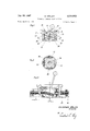
- FIGURE 4 shows a second embodiment of a control stick system constructed in accordance with the present invention
- FIGURE 5 is a cross sectional view taken along line V-V of FIGURE 4.
- FIGURE 6 illustrates how a control stick system constructed in accordance with the present invention may be combined with additional apparatus so as to control all three degrees of rotational movement of a body
- FIGURE 7 illustrates the mode of operation of a Hall generator which may be used in the present invention.
- a control stick constructed in accordance with the present invention includes a joint ball 11.
- Joint ball 11 is so constructed as to have magnetic irregularities.
- One way of introducing such irregularities is to construct the ball out of aluminum and surround the ball with a layer of ferromagnetic material.
- the ferromagnetic material is represented by reference numeral 17.
- Layer 17 may be a packet of dynamo laminations cast integral with the joint ball 11.
- the ball with the cast in dynamo laminations is machined into its final shape or else subjected to suitable surface finishing.
- the resulting structure is a ball which is smooth and easily moveable.
- the control stick system of FIGURE l further includes a socket into which the joint ball 11 and its ferromagnetic layer 17 are fitted.
- This socket is formed by a bushing 12 having a hollow spherical bearing surface 13 corresponding to the outer surface of the joint ball 11 and a ring 14 having a hollow spherical annular surface 15 also corresponding to the outer surface of joint ball 11. Ring 14 is held tightly against joint ball 11 because of the pressure exerted by a spring 16.
- the invention additionally includes means for moving the joint ball 11 in the socket formed by the bushing 12 and the ring 14. This function may be performed by an elongated handle 10 fixed to the joint ball 11.
- the system of FIGURE 1 additionally includes means for sensing the movement of the magnetic irregularities in the joint ball 11. This sensing may be accomplished by a packet of laminations 18 which surrounds the joint ball 11 and a plurality of exciting and pick-olf coils wound on laminations 18.
- the manner in which the exciting and pick-olf coils are wound may be most readily understood by referring to FIGURES 2 and 3. As shown in these figures, four exciting coils 19, 20, 21 and 22 are physically positioned apart and are connected in series across an alternating voltage source (not shown) between a pair of terminals 1 and 2 by way of a switch 23. Positioned on both sides of the exciting coils 19 and 21 are pairs of pick-off coils 24, 25 and 26, 27 respectively.
- coils 26 and 27 are connected in opposition to coils 24 and 25. If the same voltage is induced in each of the pick-off coils 24, 25, 26 and 27, the resultant signal developed across a pair of terminals 3 and 4 is zero.
- pairs of pick-off coils 28, 29 and 30, 31 are positioned on both sides of the exciting coils 20 and 22 respe-ctively. Coils 30 and 31 are connected in opposition to coils 28 and 29. If the same voltage is induced in each of the coils 28, 29, 30 and 31 the resultant signal developed across a pair of terminals 5 and 6 is zero.
- Pick-off coils 24, 25, 26 and 27 may be thought of as the pitch pick-off coils so that the signals developed across terminals 3 and 4 may be thought of as representing pitch movements.
- Pick-off coils 28, 29, 30 and 31 may be thought of as the roll pick-off coils so ,that
- the signals developed across terminals 5 and 6 may be thought of as representing roll movements.
- Each of the pick-oft coils is inductively coupled with the adjacent exciting coil.
- the magnetic circuit of each such coupling is completed through the packet 17 on the joint ball 11.
- the packet 17 of joint ball 11 moves with respect to the packet 1S in such a way that the magnetic coupling between exciting coil 22 and pickoff coils 30 and 31 is increased. This results in an increase in the voltages induced in the pickoff coils 30 and 31.
- the packet 17 moves away from the exciting coil 20 and the pick-off coils 28 and 29 so that the magnetic couplings between exciting coil 20 and pick-ott coils 28 and 29 decrease. This results in a decrease in the voltages induced in the pick-off coils 28 and 29.
- the magnetic coupling between exciting coil 19 and pick-off coil 24 and the magnetic coupling between exciting coil 21 and pick-off coil 27 increase to the same extent as the decrease in coupling between the exciting coil 19 and pick-off coil 25, and the decrease in coupling between exciting coil 21 and pick-oi coil 26.
- the resultant signal developed across terminals 3 and 4 is zero since coils 24 and 25 are connected in series as are coils 26 and 27.
- a switch 23 is provided in the input lines which supply alternating current to the exciting coils. Switch 23 is so arranged as to continuously attempt to remain in an open condition. However, with a deection of the control stick 10 in any direction, switch 23 is kept closed due to member 32 being pushed downward. However, when the control stick 10 is in its central position, member 32 yields into the recess 33 in joint ball 11 thereby permitting switch 23 to open.
- switch 23 interrupts the current being supplied to the exciting coils and thus prevents the development of signals at terminals 3, 4 and 5, 6 since under such conditions no voltages can be induced in the pick-oit coils.
- switch 23 is shown to be in the exciting coil circuitry, it will be obvious that this switch may instead be located in the pick-oit coil circuitry.
- FIG URE 4 Description and operation of FIG URE 4 control stick system
- the control stick system of FIGURE 4 is generally similar to the control stick system ⁇ of FIGURE l. Therefore, elements in FIGURE 4 corresponding to elements in FIGURE l have been given the same reference numerals.
- the point ball 11 is seen to include a magnet 34 having two pole pieces 35 and 36 separated from each other by a gap 37 which becomes narrower further along the radius of the ball.
- FIGURE 5 is a cross-sectional view taken along lines V-V of FIGURE 4.
- the joint ball 11 is surrounded by a ferromagnetic jacket 38 comprising a cup-shaped receiver with a nonmagnetic bearing body 12 into which the joint ball 11 is iitted.
- the ferromagnetic jacket 38 is of inner square cross section.
- the movement of the joint ball 11 of FIGURE 4 is sensed by a plurality of Hall generators which respond to the magnetic eld created by the magnet 34.
- a plurality of Hall generators which respond to the magnetic eld created by the magnet 34.
- a Hall generator comprises a thin lamina 5t) of semi-conducting material to which are attached a pair of electrodes 51 and 52.
- a control current is supplied to the lamina 50 by way of electrodes 51 and 52. If a magnetic iield extends through the lamina 5t), a Hall voltage is developed which is perpendicular to the direction of the control current flow and is proportional to the magnitude of the control current and the magnetic field.
- the four Hall generators receive the lines of magnetic tlux which extend outwardly in the area of the north pole of magnet 34 and pole piece 35.
- the remainder of the magnetic circuit is composed of the ferromagnetic jacket 38, pole piece 36 and the south pole of magnet 34.
- the lines of magnetic llux extend inwardly in the area -of the south pole of magnet 34 and pole piece 36.
- the four Hall generators are connected electrically in such a way that the signals develop by oppositely disposed generators are effectively in phase opposition.
- the Hall generators either are not cut by lines of magnetic ux or are cut uniformly with the same amount of flux entering the generators at their tops as emanates from the generators at their bottoms. Under either condition, no Hall voltages are developed by the Hall generators. Even if voltages were induced under these conditions, they would mutually cancel each other due to the manner in which oppositely disposed Hall generators are connected.
- Hall generator 42 is cut by lines of magnetic flux which extend inwardly into the south magnetic pole of magnet 34, while Hall generator 40 is cut by lines of magnetic ux which extend outwardly from the north magnetic pole of magnet 34.
- the Hall voltages induced in generators 40 and 42 are added with the net signal being ⁇ a measure of the amount of deflection in the roll direction.
- FIGURE 6 shows how a control stick system constructed in accordance With the present invention may be combined with additional apparatus of conventional construction and operation so as to control a body in all three degrees of rotational movement.
- Elements in FIG- URE 6 corresponding to elements in FIGURES 1-5 have been given the same reference numerals and a description of these elements will be omitted.
- the additional apparatus for sensing the third degree of rotational movement, yaw includes a rotatable con. trol member 43. Also included in this additional apparatus is a stator winding 44. As rotatable control member 43 rotates about the yaw axis, control signals representative of such rotation are developed.
- a control stick system comprising:
- a joint ball formed of a nonmagnetic material and supporting magnetic irregularities
- means comprising a lever arm attached to said ball for moving said joint ball in said socket by the application of a manual force thereto;
- a control stick system comprising:
- a joint ball formed of a nonmagnetic material and supporting magnetic irregularities
- means comprising a lever arm attached to said ball for moving said joint ball in said socket by the application of a manual force thereto to traverse said magnetic fields;
- a control stick system comprising:
- a joint ball including a magnet having a north and a south pole
Description
Egg-351,972
.Fuy 18, 1967 vv. MLLER MAGNETIC CONTROL STICK SYSTEM 5 Sheets-Sheet l Filed April 15, 1964 31 24 19 zs 2o 29 26 27 WALDEMAR MLLER INVENTOR.
juy S, w67 vv. 'MLLER 3,331,972
MAGNETIC CONTROL STICK SYSTEM Filed April l5, 1964 3 Sheets-Sheet .2
WALDEMAR MLLER INVENTOR.
July 18, 1967 W. MLLER 3,331,972-
MAGNETIC CONTROVL STICK SYSTEM Filed April l5, 1964 3 SheeiS-Sheet 3 'l/W MIWV IN VEN TOR. Waldemar Hller HTTRNEY.'
United States Patent O 3,331,972 MAGNETIC CONTROL STICK SYSTEM Waldemar Mller, Heiligenberg, Baden, Germany, assignor to Bodenseewerk Perkin-Elmer & Co. G.m.b.H., berlingen am Bodensee, Germany Filed Apr. 15, 1964, Ser. No. 360,025 Claims. (Cl. S10- 10) The present invention relates to a control stick system particularly useful for steering or controlling airplanes and other types of vehicles. The invention is directed toward the ball-and-socket joint type of control wherein control signals are developed from the rotation of a ball within a socket.
One well known technique for sensing the position of a control stick involves the use of a potentiometer having its slider connected to the control stick. On movement of the control stick, the potentiometer slider moves along the potentiometer resistor and electrical signals representative of the movement of the control stick are thus developed. While this arrangement may be adequate for one-dimensional movements of the control stick, it has been found that certain structural difliculties are encountered when this technique is utilized to sense the movement of the control stick in two dimensions.
Another well known arrangement for sensing the movements of control sticks employs inductive or capacitive pick-off systems. In such an arrangement, the control stick is rigidly supported at one end and deliected at the other end. The inductive or capacitive pick-off system is positioned at that end of the stick which is deflected. As the stick is deflected, the values of the inductors or capacitors change accordingly. These changes are sensed and electrical signals representative of these changes are developed. Such arrangements have been found adequate for detecting microscopic deflections of the control stick provided that cost and complexity of the system were not obstacles. In addition, such arrangements possess the very desirable feature that the operator is able to sense the degree and direction of pressure exerted on the stick without requiring a visual check of the movement. However, as already indicated, such an arrangement may involve the design of an extremely complex and .costly system. Also, it has been found that the inductive or capacitive pick-olf systems are not suitable for sensing macroscopic movements.
It is an object of the present invention to provide a new and improved control stick system.
It is another object of the present invention to provide a ball-and-socket joint control which is simple in construction and inexpensive to fabricate.
It is a further object of the present invention to provide a new and improved ball-and-socket joint control which is not subject to the limitations and shortcomings of presently utilized arrangements.
A control stick system constructed in accordance with the present invention comprises a joint ball having magnetic irregularities and a socket into which the joint ball is fitted. The invention additionally includes means for moving the joint ball in the socket and means for sensing the movement of the electromagnetic irregularities in the joint ball.
For a better understanding of the present invention, together with other and further objects thereof, reference is had to the following description, taken in connection with the accompanying drawings, and its scope will be pointed out in the appended claims.
Referring to the drawings:
FIGURE l shows one embodiment of a control stick system constructed in accordance with the present invention;
FIGURE 2 shows the manner in which the excitation ICC and sensing coils used in the FIGURE 1 control stick system may be arranged;
FIGURE 3 shows the excitation and sensing ,coil of FIGURE 2 drawn into a single plane;
FIGURE 4 shows a second embodiment of a control stick system constructed in accordance with the present invention;
FIGURE 5 is a cross sectional view taken along line V-V of FIGURE 4;
FIGURE 6 illustrates how a control stick system constructed in accordance with the present invention may be combined with additional apparatus so as to control all three degrees of rotational movement of a body; and
FIGURE 7 illustrates the mode of operation of a Hall generator which may be used in the present invention.
Referring to FIGURE 1, a control stick constructed in accordance with the present invention includes a joint ball 11. Joint ball 11 is so constructed as to have magnetic irregularities. One way of introducing such irregularities is to construct the ball out of aluminum and surround the ball with a layer of ferromagnetic material. The ferromagnetic material is represented by reference numeral 17. Layer 17 may be a packet of dynamo laminations cast integral with the joint ball 11. The ball with the cast in dynamo laminations is machined into its final shape or else subjected to suitable surface finishing. The resulting structure is a ball which is smooth and easily moveable.
The control stick system of FIGURE l further includes a socket into which the joint ball 11 and its ferromagnetic layer 17 are fitted. This socket is formed by a bushing 12 having a hollow spherical bearing surface 13 corresponding to the outer surface of the joint ball 11 and a ring 14 having a hollow spherical annular surface 15 also corresponding to the outer surface of joint ball 11. Ring 14 is held tightly against joint ball 11 because of the pressure exerted by a spring 16.
The invention additionally includes means for moving the joint ball 11 in the socket formed by the bushing 12 and the ring 14. This function may be performed by an elongated handle 10 fixed to the joint ball 11.
The system of FIGURE 1 additionally includes means for sensing the movement of the magnetic irregularities in the joint ball 11. This sensing may be accomplished by a packet of laminations 18 which surrounds the joint ball 11 and a plurality of exciting and pick-olf coils wound on laminations 18. The manner in which the exciting and pick-olf coils are wound may be most readily understood by referring to FIGURES 2 and 3. As shown in these figures, four exciting coils 19, 20, 21 and 22 are physically positioned apart and are connected in series across an alternating voltage source (not shown) between a pair of terminals 1 and 2 by way of a switch 23. Positioned on both sides of the exciting coils 19 and 21 are pairs of pick- off coils 24, 25 and 26, 27 respectively. As is evident from FIGURES 2 and 3, coils 26 and 27 are connected in opposition to coils 24 and 25. If the same voltage is induced in each of the pick- off coils 24, 25, 26 and 27, the resultant signal developed across a pair of terminals 3 and 4 is zero.
In a similar manner, pairs of pick- off coils 28, 29 and 30, 31 are positioned on both sides of the exciting coils 20 and 22 respe-ctively. Coils 30 and 31 are connected in opposition to coils 28 and 29. If the same voltage is induced in each of the coils 28, 29, 30 and 31 the resultant signal developed across a pair of terminals 5 and 6 is zero.
Pick-off coils 24, 25, 26 and 27 may be thought of as the pitch pick-off coils so that the signals developed across terminals 3 and 4 may be thought of as representing pitch movements. Pick-off coils 28, 29, 30 and 31 may be thought of as the roll pick-off coils so ,that
the signals developed across terminals 5 and 6 may be thought of as representing roll movements.
Each of the pick-oft coils is inductively coupled with the adjacent exciting coil. The magnetic circuit of each such coupling is completed through the packet 17 on the joint ball 11. When the control stick is in its central position, the same voltage is induced in each of the pickoi coils 24-31 inclusive so that the net output signals across terminals 3, 4 and terminals 5, 6 are zero.
When the control stick 10 is moved in the roll direction from its center position to a position such as is illustrated in FIGURE 1, the packet 17 of joint ball 11 moves with respect to the packet 1S in such a way that the magnetic coupling between exciting coil 22 and pickoff coils 30 and 31 is increased. This results in an increase in the voltages induced in the pickoff coils 30 and 31. At the same time, the packet 17 moves away from the exciting coil 20 and the pick-off coils 28 and 29 so that the magnetic couplings between exciting coil 20 and pick-ott coils 28 and 29 decrease. This results in a decrease in the voltages induced in the pick-off coils 28 and 29. Because pick-off coils 30, 31 are connected in opposition to coils 28 and 29, a resultant signal equal to the difference between the voltages induced in coils 30, 31 and 28, 29 is established across terminals 5 and 6. The magnitude of this resultant signal is dependent upon the amount of deection of the control stick in the roll direction and the phase of this signal is an indication of the direction of deection.
Since the assumed movement of the control stick 10 was in the roll direction only, no voltage is established across terminals 3 and 4 since the magnetic couplings between exciting coil 21 and pick-01T coils 26 and 27 change in exactly the same way as do the magnetic couplings between exciting coil 19 and pick- oit coils 24 and 25. Thus, when the voltages induced in coils 24 and 25 are added to the voltages induced in coils 26 and 27, the resultant signal is zero since coils 24, 25 are connected in opposition to coils 26, 27. Furthermore, the sum of the voltages induced in the coils 24, 25 or 26, 27 does not change appreciably with a deflection of the control stick 10 about the roll axis. The magnetic coupling between exciting coil 19 and pick-off coil 24 and the magnetic coupling between exciting coil 21 and pick-off coil 27 increase to the same extent as the decrease in coupling between the exciting coil 19 and pick-off coil 25, and the decrease in coupling between exciting coil 21 and pick-oi coil 26. The resultant signal developed across terminals 3 and 4 is zero since coils 24 and 25 are connected in series as are coils 26 and 27.
With a deection of the control stick 10 in only the pitch direction, a signal is developed across terminals 3 and 4 in the same manner as the development of signals at terminals 5 and 6 for deflections in only the roll direction. For a deflection involving a combination of both pitch and roll signals representative of the direction of deflection are developed across terminals 3, 4 and 5, 6 Without either of the signals inuencing or aifecting the other.
As previously indicated, if the control stick 10 is in its central position no signals are developed across the output terminals 3, 4 and 5, 6. Because this result is diicult to achieve even with the iinest balanced pick-off systems, a switch 23 is provided in the input lines which supply alternating current to the exciting coils. Switch 23 is so arranged as to continuously attempt to remain in an open condition. However, with a deection of the control stick 10 in any direction, switch 23 is kept closed due to member 32 being pushed downward. However, when the control stick 10 is in its central position, member 32 yields into the recess 33 in joint ball 11 thereby permitting switch 23 to open. Such an opening in switch 23 interrupts the current being supplied to the exciting coils and thus prevents the development of signals at terminals 3, 4 and 5, 6 since under such conditions no voltages can be induced in the pick-oit coils. Although switch 23 is shown to be in the exciting coil circuitry, it will be obvious that this switch may instead be located in the pick-oit coil circuitry.
Description and operation of FIG URE 4 control stick system The control stick system of FIGURE 4 is generally similar to the control stick system `of FIGURE l. Therefore, elements in FIGURE 4 corresponding to elements in FIGURE l have been given the same reference numerals.
Referring to FIGURE 4, the point ball 11 is seen to include a magnet 34 having two pole pieces 35 and 36 separated from each other by a gap 37 which becomes narrower further along the radius of the ball. FIGURE 5 is a cross-sectional view taken along lines V-V of FIGURE 4. The joint ball 11 is surrounded by a ferromagnetic jacket 38 comprising a cup-shaped receiver with a nonmagnetic bearing body 12 into which the joint ball 11 is iitted. For the arrangement shown in FIGURES 4 and 5, the ferromagnetic jacket 38 is of inner square cross section.
The movement of the joint ball 11 of FIGURE 4 is sensed by a plurality of Hall generators which respond to the magnetic eld created by the magnet 34. For the FIG- URE 4 arrangement, there are four Hall generators 39, 40, 41, and 42 arranged in the centers of the four sides of the square in the interior of ferromagnetic jacket 38.
Referring to FIGURE 7, a Hall generator comprises a thin lamina 5t) of semi-conducting material to which are attached a pair of electrodes 51 and 52. A control current is supplied to the lamina 50 by way of electrodes 51 and 52. If a magnetic iield extends through the lamina 5t), a Hall voltage is developed which is perpendicular to the direction of the control current flow and is proportional to the magnitude of the control current and the magnetic field.
The four Hall generators receive the lines of magnetic tlux which extend outwardly in the area of the north pole of magnet 34 and pole piece 35. The remainder of the magnetic circuit is composed of the ferromagnetic jacket 38, pole piece 36 and the south pole of magnet 34. The lines of magnetic llux extend inwardly in the area -of the south pole of magnet 34 and pole piece 36. The four Hall generators are connected electrically in such a way that the signals develop by oppositely disposed generators are effectively in phase opposition. As long as the control stick 10 is in its central position, the Hall generators either are not cut by lines of magnetic ux or are cut uniformly with the same amount of flux entering the generators at their tops as emanates from the generators at their bottoms. Under either condition, no Hall voltages are developed by the Hall generators. Even if voltages were induced under these conditions, they would mutually cancel each other due to the manner in which oppositely disposed Hall generators are connected.
When the control stick 10 is deilected in the roll direction as indicated in FIGURE 4, Hall generator 42 is cut by lines of magnetic flux which extend inwardly into the south magnetic pole of magnet 34, while Hall generator 40 is cut by lines of magnetic ux which extend outwardly from the north magnetic pole of magnet 34. The Hall voltages induced in generators 40 and 42 are added with the net signal being `a measure of the amount of deflection in the roll direction.
Similar results occur for deflections of the control stick 10 in only the pitch direction and `for deflections having components in both the pitch and roll directions.
FIGURE 6 shows how a control stick system constructed in accordance With the present invention may be combined with additional apparatus of conventional construction and operation so as to control a body in all three degrees of rotational movement. Elements in FIG- URE 6 corresponding to elements in FIGURES 1-5 have been given the same reference numerals and a description of these elements will be omitted.
The additional apparatus for sensing the third degree of rotational movement, yaw, includes a rotatable con. trol member 43. Also included in this additional apparatus is a stator winding 44. As rotatable control member 43 rotates about the yaw axis, control signals representative of such rotation are developed.
While there has been described what are at present considered to be the preferred embodiments of this invention, it will be obvious to those skilled in the art that various changes and modications may be made therein without departing from the invention, and it is therefore aimed to cover all such changes and modications as all within the true spirit and scope of the invention.
I claim:
1. A control stick system comprising:
a joint ball formed of a nonmagnetic material and supporting magnetic irregularities;
a socket into which said joint ball is fitted;
means comprising a lever arm attached to said ball for moving said joint ball in said socket by the application of a manual force thereto;
and means for sensing the movement of said magnetic irregularities.
2. A control stick system according to claim 1 wherein the joint ball comprises a nonmagnetic material surrounded by a layer of ferromagnetic material.
3. A control stick system comprising:
a joint ball formed of a nonmagnetic material and supporting magnetic irregularities;
a socket into which said joint ball is fitted;
a first plurality of windings for developing a plurality of magnetic fields which are directed toward said joint ball;
means comprising a lever arm attached to said ball for moving said joint ball in said socket by the application of a manual force thereto to traverse said magnetic fields;
and a second plurality of windings responsive to said traversed magnetic fields for sensing the movement of said magnetic irregularities in said joint ball.
4. A control stick system according to claim 1 wherein the joint ball is a magnet.
5. A control stick system comprising:
a joint ball including a magnet having a north and a south pole;
a socket into which said joint ball is tted;
means for moving said joint ball in said socket;
and a plurality of Hall generators responsive to the magnetic eld emanating from said north pole and entering said south pole `for sensing the movement of said magnet.
References Cited UNITED STATES PATENTS 1,589,039 6/1926 AnschutZ-Kaempe 308-10 2,736,869 2/1956 Rex 336-30 2,924,633 2/ 1960 Sichling. 3,209,602 10/1965 Biderman 308--10 X MILTON O. HIRSHFIELD, Primary Examiner.
D. X. SLINEY, Assistant Examiner.
Claims (1)
- 5. A CONTROL STICK SYSTEM COMPRISING: A JOINT BALL INCLUDING A MAGNET HAVING A NORTH AND A SOUTH POLE; A SOCKET INTO WHICH SAID JOINT BALL IS FITTED; MEANS FOR MOVING SAID JOINT BALL IN SAID SOCKET; AND A PLURALITY OF HALL GENERATORS RESPONSIVE TO THE MAGNETIC FIELD EMANATING FROM SAID NORTH POLE AND ENTERING SAID SOUTH POLE FOR SENSING THE MOVEMENT OF SAID MAGNET.
Priority Applications (1)
| Application Number | Priority Date | Filing Date | Title |
|---|---|---|---|
| US360025A US3331972A (en) | 1964-04-15 | 1964-04-15 | Magnetic control stick system |
Applications Claiming Priority (1)
| Application Number | Priority Date | Filing Date | Title |
|---|---|---|---|
| US360025A US3331972A (en) | 1964-04-15 | 1964-04-15 | Magnetic control stick system |
Publications (1)
| Publication Number | Publication Date |
|---|---|
| US3331972A true US3331972A (en) | 1967-07-18 |
Family
ID=23416286
Family Applications (1)
| Application Number | Title | Priority Date | Filing Date |
|---|---|---|---|
| US360025A Expired - Lifetime US3331972A (en) | 1964-04-15 | 1964-04-15 | Magnetic control stick system |
Country Status (1)
| Country | Link |
|---|---|
| US (1) | US3331972A (en) |
Cited By (25)
| Publication number | Priority date | Publication date | Assignee | Title |
|---|---|---|---|---|
| US4216467A (en) * | 1977-12-22 | 1980-08-05 | Westinghouse Electric Corp. | Hand controller |
| US4459578A (en) * | 1983-01-13 | 1984-07-10 | Atari, Inc. | Finger control joystick utilizing Hall effect |
| US4500867A (en) * | 1982-01-13 | 1985-02-19 | Nec Kansai, Ltd. | Joystick controller using magnetosensitive elements with bias magnets |
| US4613818A (en) * | 1983-06-20 | 1986-09-23 | The Medical College Of Wisconsin, Inc. | Nuclear magnetic resonance blood flowmeter |
| US4639667A (en) * | 1983-05-23 | 1987-01-27 | Andresen Herman J | Contactless controllers sensing displacement along two orthogonal directions by the overlap of a magnet and saturable cores |
| US4654576A (en) * | 1984-08-28 | 1987-03-31 | Oelsch Kommanditgesellschaft | Control signal generator |
| US4733214A (en) * | 1983-05-23 | 1988-03-22 | Andresen Herman J | Multi-directional controller having resiliently biased cam and cam follower for tactile feedback |
| US4872672A (en) * | 1985-09-09 | 1989-10-10 | Microcube Corporation | Proportional control with a joystick device for inputting computer variables |
| DE3844020A1 (en) * | 1988-12-27 | 1990-06-28 | Samson Ag | Displacement sensor (position pick-up) having mechanical gearing elements |
| US4947070A (en) * | 1983-08-09 | 1990-08-07 | British Aerospace Public Limited Company | Control apparatus |
| EP0477098A2 (en) * | 1990-09-18 | 1992-03-25 | Fujitsu Limited | Cursor displacement control device for a computer display |
| US5286024A (en) * | 1991-03-20 | 1994-02-15 | Atari Games Corporation | System for sensing the position of a joystick |
| US5850142A (en) * | 1997-04-03 | 1998-12-15 | Measurement Systems, Inc. | Control device having a magnetic component with convex surfaces |
| US5969520A (en) * | 1997-10-16 | 1999-10-19 | Sauer Inc. | Magnetic ball joystick |
| US6606085B1 (en) * | 1999-09-22 | 2003-08-12 | Fujitsu Takamisawa Component Limited | Coordinate input device |
| US20060044269A1 (en) * | 2004-08-30 | 2006-03-02 | Sauer-Danfoss Inc. | Joystick device with redundant processing |
| US20060044275A1 (en) * | 2002-02-05 | 2006-03-02 | Sensopad Limited | Sensing apparatus and method |
| WO2006056170A1 (en) * | 2004-11-24 | 2006-06-01 | Zf Friedrichshafen Ag | Shifting device for a motor vehicle |
| US20060274040A1 (en) * | 2005-06-06 | 2006-12-07 | Passaro Richard M | Manual control device including a magnetoresistive sensor element |
| DE102005032145A1 (en) * | 2005-07-07 | 2007-01-11 | Zf Friedrichshafen Ag | Joint for a motor vehicle |
| US20070013556A1 (en) * | 2005-07-14 | 2007-01-18 | Gaston Darrell W | Method and system for rotary code-based control |
| US20070040802A1 (en) * | 2005-08-17 | 2007-02-22 | Sauer-Danfoss Inc. | Magnetic control device |
| US20080202904A1 (en) * | 2007-02-28 | 2008-08-28 | Werner Olbrich | Switching device having a coupling element |
| US20190138046A1 (en) * | 2017-11-07 | 2019-05-09 | Patrick A. McFadden | Array for hemispherical actuation |
| US11172604B2 (en) * | 2018-03-28 | 2021-11-16 | Nanjing Chervon Industry Co., Ltd. | Riding lawn mower lap bar position detection |
Citations (4)
| Publication number | Priority date | Publication date | Assignee | Title |
|---|---|---|---|---|
| US1589039A (en) * | 1922-02-02 | 1926-06-15 | Nl Tech Handel Mij Giro | Gyroscopic apparatus |
| US2736869A (en) * | 1952-08-20 | 1956-02-28 | Harold B Rex | Mechanico-electrical converter |
| US2924633A (en) * | 1954-03-27 | 1960-02-09 | Siemens Ag | Ignition system for internal combustion engines |
| US3209602A (en) * | 1961-08-02 | 1965-10-05 | Collins Radio Co | Drive and sensing means for ball gyroscope |
-
1964
- 1964-04-15 US US360025A patent/US3331972A/en not_active Expired - Lifetime
Patent Citations (4)
| Publication number | Priority date | Publication date | Assignee | Title |
|---|---|---|---|---|
| US1589039A (en) * | 1922-02-02 | 1926-06-15 | Nl Tech Handel Mij Giro | Gyroscopic apparatus |
| US2736869A (en) * | 1952-08-20 | 1956-02-28 | Harold B Rex | Mechanico-electrical converter |
| US2924633A (en) * | 1954-03-27 | 1960-02-09 | Siemens Ag | Ignition system for internal combustion engines |
| US3209602A (en) * | 1961-08-02 | 1965-10-05 | Collins Radio Co | Drive and sensing means for ball gyroscope |
Cited By (37)
| Publication number | Priority date | Publication date | Assignee | Title |
|---|---|---|---|---|
| US4216467A (en) * | 1977-12-22 | 1980-08-05 | Westinghouse Electric Corp. | Hand controller |
| US4500867A (en) * | 1982-01-13 | 1985-02-19 | Nec Kansai, Ltd. | Joystick controller using magnetosensitive elements with bias magnets |
| US4459578A (en) * | 1983-01-13 | 1984-07-10 | Atari, Inc. | Finger control joystick utilizing Hall effect |
| US4639667A (en) * | 1983-05-23 | 1987-01-27 | Andresen Herman J | Contactless controllers sensing displacement along two orthogonal directions by the overlap of a magnet and saturable cores |
| US4733214A (en) * | 1983-05-23 | 1988-03-22 | Andresen Herman J | Multi-directional controller having resiliently biased cam and cam follower for tactile feedback |
| US4613818A (en) * | 1983-06-20 | 1986-09-23 | The Medical College Of Wisconsin, Inc. | Nuclear magnetic resonance blood flowmeter |
| US4947070A (en) * | 1983-08-09 | 1990-08-07 | British Aerospace Public Limited Company | Control apparatus |
| US4654576A (en) * | 1984-08-28 | 1987-03-31 | Oelsch Kommanditgesellschaft | Control signal generator |
| US4872672A (en) * | 1985-09-09 | 1989-10-10 | Microcube Corporation | Proportional control with a joystick device for inputting computer variables |
| DE3844020A1 (en) * | 1988-12-27 | 1990-06-28 | Samson Ag | Displacement sensor (position pick-up) having mechanical gearing elements |
| EP0477098A2 (en) * | 1990-09-18 | 1992-03-25 | Fujitsu Limited | Cursor displacement control device for a computer display |
| EP0477098A3 (en) * | 1990-09-18 | 1992-07-29 | Fujitsu Limited | Cursor displacement control device for a computer display |
| US5504502A (en) * | 1990-09-18 | 1996-04-02 | Fujitsu Limited | Pointing control device for moving a cursor on a display on a computer |
| US5286024A (en) * | 1991-03-20 | 1994-02-15 | Atari Games Corporation | System for sensing the position of a joystick |
| US5850142A (en) * | 1997-04-03 | 1998-12-15 | Measurement Systems, Inc. | Control device having a magnetic component with convex surfaces |
| US5969520A (en) * | 1997-10-16 | 1999-10-19 | Sauer Inc. | Magnetic ball joystick |
| US6606085B1 (en) * | 1999-09-22 | 2003-08-12 | Fujitsu Takamisawa Component Limited | Coordinate input device |
| US20060044275A1 (en) * | 2002-02-05 | 2006-03-02 | Sensopad Limited | Sensing apparatus and method |
| US7554527B2 (en) * | 2002-02-05 | 2009-06-30 | Sensopad Limited | Sensing apparatus and method |
| US7757579B2 (en) | 2004-08-30 | 2010-07-20 | Sauer-Danfoss Inc. | Joystick device with redundant sensor processing |
| US20060044269A1 (en) * | 2004-08-30 | 2006-03-02 | Sauer-Danfoss Inc. | Joystick device with redundant processing |
| WO2006056170A1 (en) * | 2004-11-24 | 2006-06-01 | Zf Friedrichshafen Ag | Shifting device for a motor vehicle |
| US7829805B2 (en) | 2004-11-24 | 2010-11-09 | Zf Friedrichshafen Ag | Shifting device for a motor vehicle |
| US20060274040A1 (en) * | 2005-06-06 | 2006-12-07 | Passaro Richard M | Manual control device including a magnetoresistive sensor element |
| US8089459B2 (en) | 2005-06-06 | 2012-01-03 | Measurement Systems, Inc. | Manual control device including a magnetoresistive sensor element |
| DE102005032145A1 (en) * | 2005-07-07 | 2007-01-11 | Zf Friedrichshafen Ag | Joint for a motor vehicle |
| US20080315867A1 (en) * | 2005-07-07 | 2008-12-25 | Joachim Spratte | Joint for a Motor Vehicle |
| US20070013556A1 (en) * | 2005-07-14 | 2007-01-18 | Gaston Darrell W | Method and system for rotary code-based control |
| US7552897B2 (en) * | 2005-07-14 | 2009-06-30 | The Boeing Company | Method and system for rotary code-based control |
| US20070040802A1 (en) * | 2005-08-17 | 2007-02-22 | Sauer-Danfoss Inc. | Magnetic control device |
| US8482523B2 (en) | 2005-08-17 | 2013-07-09 | Sauer-Danfoss Inc. | Magnetic control device |
| US20080202904A1 (en) * | 2007-02-28 | 2008-08-28 | Werner Olbrich | Switching device having a coupling element |
| US7915551B2 (en) * | 2007-02-28 | 2011-03-29 | Siemens Aktiengesellschaft | Switching device having a coupling element |
| CN101257299B (en) * | 2007-02-28 | 2012-07-04 | 西门子公司 | Switching device having a coupling element |
| US20190138046A1 (en) * | 2017-11-07 | 2019-05-09 | Patrick A. McFadden | Array for hemispherical actuation |
| US11172604B2 (en) * | 2018-03-28 | 2021-11-16 | Nanjing Chervon Industry Co., Ltd. | Riding lawn mower lap bar position detection |
| US11812688B2 (en) | 2018-03-28 | 2023-11-14 | Nanjing Chervon Industry Co., Ltd. | Riding lawn mower and operating apparatus with position detection for the same |
Similar Documents
| Publication | Publication Date | Title |
|---|---|---|
| US3331972A (en) | Magnetic control stick system | |
| US3331971A (en) | Magnetic control stick system | |
| US2488734A (en) | Dynamo transformer | |
| US4661737A (en) | Electrical machines with multiple axes of rotation | |
| US2569105A (en) | Magnetic position responsive device | |
| US2361433A (en) | Magnetic compass | |
| US4487083A (en) | Pick-off, torquer, and reference signal generator for free rotor gyroscopes | |
| US3107540A (en) | Gyroscope pickoff and torquer | |
| US3178696A (en) | Position transducers | |
| US5763972A (en) | Magnetic bearing with alternating actuators and sensors | |
| US2730664A (en) | Induction signal motor-operated differential transformer | |
| US2196809A (en) | Telemetric system | |
| US3327541A (en) | Signal pickoff and torque generator | |
| US3152275A (en) | Torquing apparatus | |
| US3323040A (en) | Combined pick-off and torquer having torquing signal superimposed on excitation or pick-off winding | |
| US3188540A (en) | Signal pick-off and d.c. torquer | |
| US2847664A (en) | Gyroscope pick-off devices | |
| US3085192A (en) | Variable output transformer | |
| US4095177A (en) | Transducer | |
| US2756357A (en) | Dynamoelectric device | |
| US2407657A (en) | Transformer pick-off | |
| US3121851A (en) | Electromagnetic transducer | |
| US3475971A (en) | Combination two-axis electromagnetic torque and pickoff | |
| US2888635A (en) | Stick force transducer | |
| US2429612A (en) | Gyroscope |