US3302012A - Lighting system utilizing the floodlight principle - Google Patents
Lighting system utilizing the floodlight principle Download PDFInfo
- Publication number
- US3302012A US3302012A US378246A US37824664A US3302012A US 3302012 A US3302012 A US 3302012A US 378246 A US378246 A US 378246A US 37824664 A US37824664 A US 37824664A US 3302012 A US3302012 A US 3302012A
- Authority
- US
- United States
- Prior art keywords
- light
- conducting
- principle
- floodlight
- reflecting surfaces
- Prior art date
- Legal status (The legal status is an assumption and is not a legal conclusion. Google has not performed a legal analysis and makes no representation as to the accuracy of the status listed.)
- Expired - Lifetime
Links
- 238000005286 illumination Methods 0.000 claims description 16
- 238000000227 grinding Methods 0.000 description 7
- 238000003801 milling Methods 0.000 description 6
- 238000012986 modification Methods 0.000 description 4
- 230000004048 modification Effects 0.000 description 4
- 238000010586 diagram Methods 0.000 description 3
- 235000019646 color tone Nutrition 0.000 description 2
- 238000013461 design Methods 0.000 description 2
- 238000000034 method Methods 0.000 description 2
- 239000000203 mixture Substances 0.000 description 2
- 230000001105 regulatory effect Effects 0.000 description 2
- 238000010521 absorption reaction Methods 0.000 description 1
- 238000013459 approach Methods 0.000 description 1
- 239000011248 coating agent Substances 0.000 description 1
- 238000000576 coating method Methods 0.000 description 1
- 238000004040 coloring Methods 0.000 description 1
- 238000009500 colour coating Methods 0.000 description 1
- 239000004020 conductor Substances 0.000 description 1
- 238000010276 construction Methods 0.000 description 1
- 238000011161 development Methods 0.000 description 1
- 230000000694 effects Effects 0.000 description 1
- 230000007257 malfunction Effects 0.000 description 1
- 239000002184 metal Substances 0.000 description 1
- 238000002156 mixing Methods 0.000 description 1
- 230000000149 penetrating effect Effects 0.000 description 1
- 230000005855 radiation Effects 0.000 description 1
- 238000012216 screening Methods 0.000 description 1
- 230000007704 transition Effects 0.000 description 1
- 239000012780 transparent material Substances 0.000 description 1
Images

Classifications
-
- H—ELECTRICITY
- H03—ELECTRONIC CIRCUITRY
- H03J—TUNING RESONANT CIRCUITS; SELECTING RESONANT CIRCUITS
- H03J1/00—Details of adjusting, driving, indicating, or mechanical control arrangements for resonant circuits in general
- H03J1/02—Indicating arrangements
- H03J1/04—Indicating arrangements with optical indicating means
- H03J1/044—Illumination of the tuning dial; On and off switching of the illumination; Circuits related with illumination
-
- B—PERFORMING OPERATIONS; TRANSPORTING
- B60—VEHICLES IN GENERAL
- B60Q—ARRANGEMENT OF SIGNALLING OR LIGHTING DEVICES, THE MOUNTING OR SUPPORTING THEREOF OR CIRCUITS THEREFOR, FOR VEHICLES IN GENERAL
- B60Q3/00—Arrangement of lighting devices for vehicle interiors; Lighting devices specially adapted for vehicle interiors
- B60Q3/10—Arrangement of lighting devices for vehicle interiors; Lighting devices specially adapted for vehicle interiors for dashboards
- B60Q3/14—Arrangement of lighting devices for vehicle interiors; Lighting devices specially adapted for vehicle interiors for dashboards lighting through the surface to be illuminated
-
- B—PERFORMING OPERATIONS; TRANSPORTING
- B60—VEHICLES IN GENERAL
- B60Q—ARRANGEMENT OF SIGNALLING OR LIGHTING DEVICES, THE MOUNTING OR SUPPORTING THEREOF OR CIRCUITS THEREFOR, FOR VEHICLES IN GENERAL
- B60Q3/00—Arrangement of lighting devices for vehicle interiors; Lighting devices specially adapted for vehicle interiors
- B60Q3/10—Arrangement of lighting devices for vehicle interiors; Lighting devices specially adapted for vehicle interiors for dashboards
- B60Q3/16—Circuits; Control arrangements
-
- B—PERFORMING OPERATIONS; TRANSPORTING
- B60—VEHICLES IN GENERAL
- B60Q—ARRANGEMENT OF SIGNALLING OR LIGHTING DEVICES, THE MOUNTING OR SUPPORTING THEREOF OR CIRCUITS THEREFOR, FOR VEHICLES IN GENERAL
- B60Q3/00—Arrangement of lighting devices for vehicle interiors; Lighting devices specially adapted for vehicle interiors
- B60Q3/60—Arrangement of lighting devices for vehicle interiors; Lighting devices specially adapted for vehicle interiors characterised by optical aspects
- B60Q3/62—Arrangement of lighting devices for vehicle interiors; Lighting devices specially adapted for vehicle interiors characterised by optical aspects using light guides
- B60Q3/64—Arrangement of lighting devices for vehicle interiors; Lighting devices specially adapted for vehicle interiors characterised by optical aspects using light guides for a single lighting device
-
- G—PHYSICS
- G09—EDUCATION; CRYPTOGRAPHY; DISPLAY; ADVERTISING; SEALS
- G09F—DISPLAYING; ADVERTISING; SIGNS; LABELS OR NAME-PLATES; SEALS
- G09F13/00—Illuminated signs; Luminous advertising
-
- B60K2360/336—
Definitions
- FIG.5 LIGHTING SYSTEM UTILIZING THE FLOODLIGHT PRINCIPLE Filed June 26, 1964 3 Sheets-Sheet 1 FIG.4 FIG.5
- the sides or the surfaces of the light-conducting body may be formed in any specific shape, for example by grinding or milling, and portions thereof may be covered so that the light emanates only at a desired point. Particularly in the illumination of indicating and measuring instruments, as well as radio dials and the like, this spacesaving method of illumination has proved satisfactory. Not only plane surfaces such as radio dials but also spatial devices may be illuminated in this manner, if desired.
- plate, bar, or rod-shaped lightconducting bodies are disposed around a surface to be illuminated and are ground in a special manner. It is also known to obtain colored illumination by coloring the light-conducting bodies or by mounting colored filters between the light source and the light-conducting body.
- Several light-conducting bodies are also frequently employed and a special color is assigned to each of them so that individual parts of a dial, for example, may be illuminated with a varicolored light.
- the present invention relates to the illumination of instruments or dials and the like in observation and operating locations such as the control cabins or cockpits of aircraft, for example. It is known to provide, in an illuminating system operating according to the floodlight principle, several light sources around one instrument or instrument group and to illuminate the entire group by means of a common light-conducting body. Plate, rod, bar, or ring-shaped light-conducting bodies are used for this purpose. In actual practice, one of the requirements is that the degree of brightness or luminosity of the light directed upon the instruments be coordinated or matched with respect to the ambient brightness or luminosity.
- the present invention provides a system utilizing the floodlight principle wherein differently-phased light is irradiated toward both ends of a light-conducting body and in which the aforementioned disadvantages and drawbacks are effectively avoided.
- the light-conducting body is provided with reflecting surfaces which extend from the extremities thereof and which are formed, by grinding or milling and the like, in the lightconducting body independently of each other.
- a light source is mounted at each end of the light-conducting body.
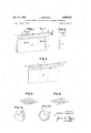
- FIGURE 1 shows one embodiment of the present invention, using mixed light, with a rod-shaped light-conducting body
- FIGURE 1a is a sectional view taken on line 1a1a of FIGURE 1,
- FIGURE lb is a sectional view taken on line lb1b of FIGURE 1,
- FIGURE 2 is an end view of the device of FIGURE 1,
- FIGURE 3 is a modification of the device of FIGURE 1, in which a portion of the reflecting surface of the light-conducting body is formed in. a specific shape,
- FIGURES 4 and 5 are two alternative forms of screens used for screening the reflecting surfaces, the screens being shown in an enlarged scale,
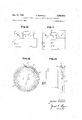
- FIGURE 6 shows the illumination of a large surface using a plurality of light-conducting bodies and light sources in accordance with the present invention
- FIGURE 7 is a view in cross-section of the device shown in FIGURE 6,
- FIGURE 8 shows the illumination of a large instrument panel using the lighting system of the present invention
- FIGURE 9 is a view in cross-section of the instrument panel shown in FIGURE 8,
- FIGURES 10 and 11 are wiring diagrams showing means for regulating the intensity of the light radiated by the systems
- FIGURE 12 is one embodiment of the use of mixed light in a circular or ring-shaped light-conducting body
- FIGURE 13 is a view in cross-section of the device of FIGURE 12.
- FIGURE 1 there is shown therein a simple embodiment of the present invention in which a plane surface 4 is desired to be lighted or illuminated according to the floodlight principle of the present invention.
- a rod or bar-shaped light-conducting body 1 having the longitudinal reflecting surfaces 1 and 1", extends approximately along one of the edges of the surface 4 and, at the end faces thereof, there are mounted the two light sources 2 and 6, respectively.
- the two light sources may be switched on either individually or collectively.
- white light is employed in the light source 2 and this light source is switched on, the illumination of the surface 4 will be effected with white light by means of the lightconducting rod l.
- the light source 6 mounted at the opposite end of the light-conducting body 1 is, in this case, a red incandescent lamp.
- this lamp 6 When this lamp 6 is individually switched on, the surface 4 is illuminated with red light. To produce a mixture of light, the light sources 2 and 6 may be switched on collectively and a mixed light M, which is composed of red and white light, is then radiated on the surface 4. By regulating the inten sity of the individual light sources, a continuous transition or blending of light may be obtained. Thus, all of the color gradations or shades of mixed light between pure white and pure red are obtainable as desired.
- the regulation of the intensity of the lights may be effected in a conventional manner, e.g. by a resistance control in the electric circuit or by means of mechanically actuated diaphragms and the like.
- One reflecting surface is provided in the light-conducting rod for each light source and the surface increases in width with increasing distance from the light source. In this manner, the absorption of the light in the light-conducting rod is compensated and the same amount of light i transmitted by the light-conducting rod to the surface to be illuminated regardless 0f the distance of the particular portion of the rod from the light source.
- the light-conducting body It is a round rod which is provided in a simple manner with two oppositely directed reflecting surfaces, which are formed by grinding, milling, or the like.
- the reflecting surfaces may be formed by grinding the rod off, starting from each end of the round rod and working in a direction toward the opposite end thereof, the grinding or milling operation penetrating into the rod. This operation is effected in a manner such that the two resulting reflecting surfaces do not overlap or cross one another.
- Two oppositely disposed separate reflecting surfaces are visible in the top plan view. The closer the grinding or milling of the rod approaches the center of the rod, viewed in cross-section, the wider becomes the reflecting surface.
- the round rod may be replaced by a different light-conducting body having a prismatic cross-section, for example.
- FIGURE 3 discloses a modification of the lighting sys tem of FIGURE 1 in which two white light sources 2 are disposed at each end of the light-conducting body I.
- Differently colored light is obtained in this embodiment by using a portion of the surface of the light-conducting body formed in a particular manner and being positioned within the region or range of total reflection.
- This portion of the light-conducting body is colored, i.e., it is coated with a colored reflecting layer or the like.
- a mixed light illumination M is obtained here again over the entire surface
- this specifically formed surface 8 provided with a colored reflecting layer may have a greater angle than the remainder of the reflecting surface.
- one or both of the reflecting surfaces of the rod 1 may be provided with such a portion having a greater angle in various sections thereof. It is also possible to utilize this concept in generally known light-conducting bodies having one reflecting surface. By means of these sections having greater angles than the remainder of the reflecting surfaces, it becomes possible to specifically illuminate and emphasize important features on the indicating instrument to be illuminated.
- the reflecting surfaces may be equipped with screens and two screen constructions are illustrated in FIGURES 4 and 5. These screens may also be covered with a colored coating or a metal layer.
- FIGURE 6 shows the illuminating system of the present invention applied to the illumination of large surfaces.
- several light rods are arranged in a row above the surface 4 to be illuminated.
- One light source 2 is positioned between each pair of the lightconducting rods and, in order to obtain differently colored light, the color filters 3 are mounted adjacent alternate light sources, which are indicated with the reference numeral 2, at the end faces of alternate pairs of lightconducting bodies 1.
- White or colored mixed light is obtained depending upon whether the light sources 2 or 2 are switched on individually or collectively.
- the light conducting rods 1 are formed as illustrated in FIGURE 1.
- FIGURE 7 shows a view in cross-section of the ar- I rangement of FIGURE 6 and shows the light sources 2 and the light-conducting bodies 1 being screened off by the cover 5, in the direction toward the viewer.
- FIGURE 8 is a further development of the device shown in FIGURE 6 and shows a lighting or illuminating device for an instrument panelcomprising the light-conducting bodies I, the white light sources 2 and the colored light sources 6. Using this particular system, disturbances which might be produced by the malfunction of one or a small number of the light sources are effectively eliminated.
- FIGURE 9 is a view in cross-section of the embodiment of FIGURE 8 and shows the provision of a screen 5 which extends over all of the light sources and the light-conducting bodies.
- FIGURE 10 there is shown a simplified Wiring or circuit diagram for the most simple case of the illuminating circuit. All of the light sources are Wired in parallel in a circuit including the current source If, the switch Ill and the regulator 9. In this arrangement, the differcntly colored light sources 2 and 6 are arranged in a row between the individual light-conducting bodies 1, shown in phantom.
- FIGURE 11 there is a circuit showing a separate regulation of the differently colored light sources.
- the white light sources are in circuit with the current source Ill, switch W, and the regulator 9, whereas the differently colored light sources 6 are in circuit with the current source ill, the switch it), and the regulator 9.
- Reference numeral ll designates the light-conducting bodies mounted between individual light sources, the bodies being shown in phantom.
- FIGURE 12 shows a circular lightconclucting body which is mounted around an indicating device 15.
- the light-conducting body 1 is provided with two separate reflecting surfaces 13 and lid, which are produced by grinding, milling or the like.
- the reflecting surface 13 is supplied with colored light from the light source 6 and the reflecting surface 14- is supplied with white light from the light source 2.
- a separating wall 12 is mounted between the light sources 2 and d for preventing a mutual influence or interference of the radiation into the reflecting surfaces. In this arrangement, it is possible to employ only a single light source for both reflecting surfaces and, in order to obtain a mixture of differently phased light, a color filter is mounted at one end face of the light-conducting body I, as shown in FIGURE 6.
- FIGURE 13 is a view in cross-section through the device of FIGURE 12 and a screen 16 for the lightconducting body 1 is shown in phantom.
- the upper left curvature of the light-conducting body is eliminated in this figure in order to show the arrangement of or mounting of the light sources 2 and 6.
- Also shown in phantom is the extension or course of the ground reflecting surface in the light-conducting body.
- the arrangement of the present invention is suitable not only for the illumination of individual instruments but also may be employed for lighting instrument groups, as noted above. It is not necessary that the surfaces to be illuminated be planar but, instead, non-planar surfaces, portions of instruments or a complete equipment layout may be illuminated using the system of the present invention. In order to produce differently colored light, interchangeable color filters may be employed. Further, the rod-shaped light-conducting bodies need not be arranged only in a row as shown in FIGURE 6 but a closed arrangement forming a rectangle and being composed of several rod-shaped light-conducting bodies may 'be positioned around the periphery of a point or area to be illuminated. These latter may be screened off from the viewer in the same manner as shown in FlGURE 7. Also, it is possible to effect not only an illumination of an area from the periphery thereof by means of lightconducting bodies, but the light-conducting bodies themselves may also be the support for dials and the like in a conventional manner.
- An illuminating system utilizing the floodlight principle comprising an elongated light-conducting body provided with light-reflecting surfaces extending from each end and to the center of the body, means for producing light rays at each end of the body, the light rays at one end being of different color from the rays at the other end, said light-reflecting surfaces each increasing in width with increasing distance from the respective light-producing means to provide uniform illumination, and means to independently vary the intensity of each light-producing means.
- An illuminating system according to claim 1 in which a portion of at least one of the light-reflecting surfaces is provided with a color coating.
- An illuminating system according to claim 1 in which a portion of at least one of the light-reflecting surfaces has a greater angle to the horizontal than the remainder thereof.
- An illuminating system according to claim 1 in which at least one colored filter is interposed between at least one of the light-producing means and the light-conducting body.
- An illuminating system in which a plurality of light-conducting bodies are mounted in series with a light-producing means between each adjacent pair.
- An illuminating system in which a plurality of light-conducting bodies are mounted in series at the periphery of an area to be illuminated, with a light-producing means between each pair of bodies, and a screen covering the light-conducting bodies and the light-producing means.
- An illuminating system according to claim 1 and including means whereby the light-producing means may be turned on and 01f independently of each other.
Description
Jan. 31, 1967 H. REPPISCH 3,302,012
LIGHTING SYSTEM UTILIZING THE FLOODLIGHT PRINCIPLE Filed June 26, 1964 3 Sheets-Sheet 1 FIG.4 FIG.5
' o0 Q g g O @559 a FIGJQ I, INVENTOR.
Hal/mm Repp/sc/r ()hp 6 M ATTOR Er Jan. 31, 1967 H. REPPISCH LIGHTING SYSTEM UTILIZING THE FLOODLIGHT PRINCIPLE 3 Sheets-Sheet 2 Filed June 26, 1964 OCT).
QQQQJQ INVENTOR. Hal/mm Feppz'sc/z BY ATTO E) Jan. 31, 1967 H. REPPISCH 3,302,012
LIGHTING SYSTEM UTILIZING THE FLOODLIGHT PRINCIPLE Filed June 26, 1964 5 Sheets-Sheet 5 FIG. IO FIG. ll
INVENTOR. Hell/m0 Reppzlrcfi ATTOR f) United States Patent 3,302,012 LIGHTING SYSTEM UTILIZING THE FLOUDLIGHT PRINCIPLE Hellmut Reppisch, Immenstaad, Germany, assignor to Dornier-Werire, G.m.b.H., Friedrichshafen am Bodensee, Germany, a corporation of Germany Filed June 26, 1964, Ser. No. 378,246 Claims priority, application Germany, June 29, 1963, D 41,862 8 Claims. ((31. 2408.16)
In the technique of lighting, the problem of illuminating plane surfaces, for example, radio dials and measuring instruments, as well as commercial signs, is frequently encountered. When light sources of conventional design are used for this purpose, large distances between the light sources and the surfaces to be illuminated are required. Such large distances, the use of which is frequently not feasible because of design considerations, can be eliminated by using the fioodlight principle. In accordance with this principle, which is known per se, a body of transparent material is laterally illuminated by a light source and, due to total reflection in the interior thereof, this body acts as a light-conductor.
The sides or the surfaces of the light-conducting body may be formed in any specific shape, for example by grinding or milling, and portions thereof may be covered so that the light emanates only at a desired point. Particularly in the illumination of indicating and measuring instruments, as well as radio dials and the like, this spacesaving method of illumination has proved satisfactory. Not only plane surfaces such as radio dials but also spatial devices may be illuminated in this manner, if desired.
In illuminating systems utilizing the floodlight principle, it is known to employ certain precautionary measures in order to obtain a uniform illumination of a desired surface. For this purpose, plate, bar, or rod-shaped lightconducting bodies are disposed around a surface to be illuminated and are ground in a special manner. It is also known to obtain colored illumination by coloring the light-conducting bodies or by mounting colored filters between the light source and the light-conducting body. Several light-conducting bodies are also frequently employed and a special color is assigned to each of them so that individual parts of a dial, for example, may be illuminated with a varicolored light.
The present invention relates to the illumination of instruments or dials and the like in observation and operating locations such as the control cabins or cockpits of aircraft, for example. It is known to provide, in an illuminating system operating according to the floodlight principle, several light sources around one instrument or instrument group and to illuminate the entire group by means of a common light-conducting body. Plate, rod, bar, or ring-shaped light-conducting bodies are used for this purpose. In actual practice, one of the requirements is that the degree of brightness or luminosity of the light directed upon the instruments be coordinated or matched with respect to the ambient brightness or luminosity. This is necessary to a particularly great extent in the cockpit or pilots compartment of aircraft in order to enable the pilot to observe the conditions both inside and outside of the cockpit or compartment without the requirement of a substantial period of time for the pilots eyes to become accustomed to different lighting conditions. In such systems, it is also desirable to illuminate the instruments selectively with differently colored lights. Thus, in addition to a white illumination for use in illuminating aircraft instruments, for example, an illumination with red light may be advisable or necessary under certain conditions.
An arrangement utilizing differently colored lights with many cases.
33%,612 Patented Jan. 31, I967 fixed color tones wherein the differently colored lights are switched on and off by simple switching operations is not of optimum utility and is often disadvantageous in The present invention provides a system utilizing the floodlight principle wherein differently-phased light is irradiated toward both ends of a light-conducting body and in which the aforementioned disadvantages and drawbacks are effectively avoided. In the system of the present invention, the light-conducting body is provided with reflecting surfaces which extend from the extremities thereof and which are formed, by grinding or milling and the like, in the lightconducting body independently of each other. A light source is mounted at each end of the light-conducting body.
The invention will be further illustrated by reference to the accompanying drawings in which FIGURE 1 shows one embodiment of the present invention, using mixed light, with a rod-shaped light-conducting body,
FIGURE 1a is a sectional view taken on line 1a1a of FIGURE 1,
FIGURE lb is a sectional view taken on line lb1b of FIGURE 1,
FIGURE 2 is an end view of the device of FIGURE 1,
FIGURE 3 is a modification of the device of FIGURE 1, in which a portion of the reflecting surface of the light-conducting body is formed in. a specific shape,
FIGURES 4 and 5 are two alternative forms of screens used for screening the reflecting surfaces, the screens being shown in an enlarged scale,
FIGURE 6 shows the illumination of a large surface using a plurality of light-conducting bodies and light sources in accordance with the present invention,
FIGURE 7 is a view in cross-section of the device shown in FIGURE 6,
FIGURE 8 shows the illumination of a large instrument panel using the lighting system of the present invention,
FIGURE 9 is a view in cross-section of the instrument panel shown in FIGURE 8,
FIGURES 10 and 11 are wiring diagrams showing means for regulating the intensity of the light radiated by the systems,
FIGURE 12 is one embodiment of the use of mixed light in a circular or ring-shaped light-conducting body, and
FIGURE 13 is a view in cross-section of the device of FIGURE 12.
Referring to FIGURE 1, there is shown therein a simple embodiment of the present invention in which a plane surface 4 is desired to be lighted or illuminated according to the floodlight principle of the present invention. A rod or bar-shaped light-conducting body 1, having the longitudinal reflecting surfaces 1 and 1", extends approximately along one of the edges of the surface 4 and, at the end faces thereof, there are mounted the two light sources 2 and 6, respectively. The two light sources may be switched on either individually or collectively. When white light is employed in the light source 2 and this light source is switched on, the illumination of the surface 4 will be effected with white light by means of the lightconducting rod l. The light source 6 mounted at the opposite end of the light-conducting body 1 is, in this case, a red incandescent lamp. When this lamp 6 is individually switched on, the surface 4 is illuminated with red light. To produce a mixture of light, the light sources 2 and 6 may be switched on collectively and a mixed light M, which is composed of red and white light, is then radiated on the surface 4. By regulating the inten sity of the individual light sources, a continuous transition or blending of light may be obtained. Thus, all of the color gradations or shades of mixed light between pure white and pure red are obtainable as desired. The regulation of the intensity of the lights may be effected in a conventional manner, e.g. by a resistance control in the electric circuit or by means of mechanically actuated diaphragms and the like. One reflecting surface is provided in the light-conducting rod for each light source and the surface increases in width with increasing distance from the light source. In this manner, the absorption of the light in the light-conducting rod is compensated and the same amount of light i transmitted by the light-conducting rod to the surface to be illuminated regardless 0f the distance of the particular portion of the rod from the light source.
As shown in FIGURE 2, one light source is provided for each reflecting surface. These light sources are mounted in an offset or staggered relationship with respect to the reflecting surfaces. In the embodiment shown, the light-conducting body It is a round rod which is provided in a simple manner with two oppositely directed reflecting surfaces, which are formed by grinding, milling, or the like. As also shown in FIGURE 1, the reflecting surfaces may be formed by grinding the rod off, starting from each end of the round rod and working in a direction toward the opposite end thereof, the grinding or milling operation penetrating into the rod. This operation is effected in a manner such that the two resulting reflecting surfaces do not overlap or cross one another. Two oppositely disposed separate reflecting surfaces are visible in the top plan view. The closer the grinding or milling of the rod approaches the center of the rod, viewed in cross-section, the wider becomes the reflecting surface. In another embodiment, the round rod may be replaced by a different light-conducting body having a prismatic cross-section, for example.
FIGURE 3 discloses a modification of the lighting sys tem of FIGURE 1 in which two white light sources 2 are disposed at each end of the light-conducting body I. Differently colored light is obtained in this embodiment by using a portion of the surface of the light-conducting body formed in a particular manner and being positioned within the region or range of total reflection. This portion of the light-conducting body is colored, i.e., it is coated with a colored reflecting layer or the like. As a result of the total reflection, a mixed light illumination M is obtained here again over the entire surface As shown in FIGURE 3, this specifically formed surface 8 provided with a colored reflecting layer may have a greater angle than the remainder of the reflecting surface. In the embodiment shown, one or both of the reflecting surfaces of the rod 1 may be provided with such a portion having a greater angle in various sections thereof. It is also possible to utilize this concept in generally known light-conducting bodies having one reflecting surface. By means of these sections having greater angles than the remainder of the reflecting surfaces, it becomes possible to specifically illuminate and emphasize important features on the indicating instrument to be illuminated.
The reflecting surfaces may be equipped with screens and two screen constructions are illustrated in FIGURES 4 and 5. These screens may also be covered with a colored coating or a metal layer.
FIGURE 6 shows the illuminating system of the present invention applied to the illumination of large surfaces. In this embodiment, several light rods are arranged in a row above the surface 4 to be illuminated. One light source 2 is positioned between each pair of the lightconducting rods and, in order to obtain differently colored light, the color filters 3 are mounted adjacent alternate light sources, which are indicated with the reference numeral 2, at the end faces of alternate pairs of lightconducting bodies 1. White or colored mixed light is obtained depending upon whether the light sources 2 or 2 are switched on individually or collectively. The light conducting rods 1 are formed as illustrated in FIGURE 1.
FIGURE 7 shows a view in cross-section of the ar- I rangement of FIGURE 6 and shows the light sources 2 and the light-conducting bodies 1 being screened off by the cover 5, in the direction toward the viewer.
FIGURE 8 is a further development of the device shown in FIGURE 6 and shows a lighting or illuminating device for an instrument panelcomprising the light-conducting bodies I, the white light sources 2 and the colored light sources 6. Using this particular system, disturbances which might be produced by the malfunction of one or a small number of the light sources are effectively eliminated.
FIGURE 9 is a view in cross-section of the embodiment of FIGURE 8 and shows the provision of a screen 5 which extends over all of the light sources and the light-conducting bodies.
In FIGURE 10 there is shown a simplified Wiring or circuit diagram for the most simple case of the illuminating circuit. All of the light sources are Wired in parallel in a circuit including the current source If, the switch Ill and the regulator 9. In this arrangement, the differcntly colored light sources 2 and 6 are arranged in a row between the individual light-conducting bodies 1, shown in phantom.
In FIGURE 11 there is a circuit showing a separate regulation of the differently colored light sources. As is apparent from the diagram, the white light sources are in circuit with the current source Ill, switch W, and the regulator 9, whereas the differently colored light sources 6 are in circuit with the current source ill, the switch it), and the regulator 9. Using this circuit, it is possible to obtain mixed light of any desired color tone. Reference numeral ll designates the light-conducting bodies mounted between individual light sources, the bodies being shown in phantom.
FIGURE 12 shows a circular lightconclucting body which is mounted around an indicating device 15. The light-conducting body 1 is provided with two separate reflecting surfaces 13 and lid, which are produced by grinding, milling or the like. The reflecting surface 13 is supplied with colored light from the light source 6 and the reflecting surface 14- is supplied with white light from the light source 2. A separating wall 12 is mounted between the light sources 2 and d for preventing a mutual influence or interference of the radiation into the reflecting surfaces. In this arrangement, it is possible to employ only a single light source for both reflecting surfaces and, in order to obtain a mixture of differently phased light, a color filter is mounted at one end face of the light-conducting body I, as shown in FIGURE 6.
FIGURE 13 is a view in cross-section through the device of FIGURE 12 and a screen 16 for the lightconducting body 1 is shown in phantom. The upper left curvature of the light-conducting body is eliminated in this figure in order to show the arrangement of or mounting of the light sources 2 and 6. Also shown in phantom is the extension or course of the ground reflecting surface in the light-conducting body.
The arrangement of the present invention is suitable not only for the illumination of individual instruments but also may be employed for lighting instrument groups, as noted above. It is not necessary that the surfaces to be illuminated be planar but, instead, non-planar surfaces, portions of instruments or a complete equipment layout may be illuminated using the system of the present invention. In order to produce differently colored light, interchangeable color filters may be employed. Further, the rod-shaped light-conducting bodies need not be arranged only in a row as shown in FIGURE 6 but a closed arrangement forming a rectangle and being composed of several rod-shaped light-conducting bodies may 'be positioned around the periphery of a point or area to be illuminated. These latter may be screened off from the viewer in the same manner as shown in FlGURE 7. Also, it is possible to effect not only an illumination of an area from the periphery thereof by means of lightconducting bodies, but the light-conducting bodies themselves may also be the support for dials and the like in a conventional manner.
It will be obvious to those skilled in the art that many modifications may be made within the scope of the pres ent invention without departing from the spirit thereof, and the invention includes all such modifications.
What is claimed is:
1. An illuminating system utilizing the floodlight principle comprising an elongated light-conducting body provided with light-reflecting surfaces extending from each end and to the center of the body, means for producing light rays at each end of the body, the light rays at one end being of different color from the rays at the other end, said light-reflecting surfaces each increasing in width with increasing distance from the respective light-producing means to provide uniform illumination, and means to independently vary the intensity of each light-producing means.
2. An illuminating system according to claim 1 in which a portion of at least one of the light-reflecting surfaces is provided with a color coating.
3. An illuminating system according to claim 1 in which a portion of at least one of the light-reflecting surfaces has a greater angle to the horizontal than the remainder thereof.
4. An illuminating system according to claim 1 in which at least one colored filter is interposed between at least one of the light-producing means and the light-conducting body.
5. An illuminating system according to claim 1 in which a plurality of light-conducting bodies are mounted in series with a light-producing means between each adjacent pair.
6. An illuminating system according to claim 1 in which the reflecting surfaces are covered by a screen.
7. An illuminating system according to claim 1 in which a plurality of light-conducting bodies are mounted in series at the periphery of an area to be illuminated, with a light-producing means between each pair of bodies, and a screen covering the light-conducting bodies and the light-producing means.
8. An illuminating system according to claim 1 and including means whereby the light-producing means may be turned on and 01f independently of each other.
References Cited by the Examiner UNITED STATES PATENTS 2,121,132 6/1938 Ryder. 2,140,972 12/1938 Rylsky 240-21 2,188,821 1/1940 Rylsky 240-2.1 2,207,117 7/ 1940 Collins -130 2,452,294 10/1948 Dickson 2408.16 2,507,035 5/1950 Maynard 2408.16 2,537,971 1/1951 Dames 2408.16 2,553,285 5/1951 Thomas 88-24 2,589,569 3/1952 Peter et a1 240-1 X 2,627,837 2/1953 Ginter 2401 X 2,689,948 9/1954 Rothrnan 2401 X 2,918,034 12/1959 Neugass 240-1 X FOREIGN PATENTS 31,104 8/1926 France.
NORTON ANSI-IER, Primary Examiner.
Claims (1)
1. AN ILLUMINATING SYSTEM UTILIZING THE FLOODLIGHT PRINCIPLE COMPRISING AN ELONGATED LIGHT-CONDUCTING BODY PROVIDED WITH LIGHT-REFLECTING SURFACES EXTENDING FROM EACH END AND TO THE CENTER OF THE BODY, MEANS FOR PRODUCING LIGHT RAYS AT EACH END OF THE BODY, THE LIGHT RAYS AT ONE END BEING OF DIFFERENT COLOR FROM THE RAYS AT THE OTHER END, SAID LIGHT-REFLECTING SURFACES EACH INCREASING IN WIDTH WITH INCREASING DISTANCE FROM THE RESPECTIVE LIGHT-PRODUCING MEANS TO PROVIDE UNIFORM ILLUMINATION, AND MEANS TO INDEPENDENTLY VARY THE INTENSITY OF EACH LIGHT-PRODUCING MEANS.
Applications Claiming Priority (1)
| Application Number | Priority Date | Filing Date | Title |
|---|---|---|---|
| DED0041862 | 1963-06-29 |
Publications (1)
| Publication Number | Publication Date |
|---|---|
| US3302012A true US3302012A (en) | 1967-01-31 |
Family
ID=7046378
Family Applications (1)
| Application Number | Title | Priority Date | Filing Date |
|---|---|---|---|
| US378246A Expired - Lifetime US3302012A (en) | 1963-06-29 | 1964-06-26 | Lighting system utilizing the floodlight principle |
Country Status (3)
| Country | Link |
|---|---|
| US (1) | US3302012A (en) |
| FR (1) | FR1399957A (en) |
| GB (1) | GB1030296A (en) |
Cited By (9)
| Publication number | Priority date | Publication date | Assignee | Title |
|---|---|---|---|---|
| US3488485A (en) * | 1966-08-19 | 1970-01-06 | Itt | Area light source |
| US3532873A (en) * | 1967-10-27 | 1970-10-06 | Ford Motor Co | Apparatus for monitoring light source operation |
| US4996632A (en) * | 1988-10-07 | 1991-02-26 | Gulton Industries, Inc. | Multi-color illuminating system |
| EP0498451A1 (en) * | 1991-02-08 | 1992-08-12 | Yazaki Corporation | Illuminating device for instrument of vehicle |
| US5219217A (en) * | 1988-10-07 | 1993-06-15 | Gulton Industries, Inc. | Illuminating system |
| US5695269A (en) * | 1996-01-29 | 1997-12-09 | Delco Electronics Corporation | Multi-color display lighting by led |
| EP1093968A3 (en) * | 1999-10-19 | 2001-10-10 | FIAT AUTO S.p.A. | A motor vehicle provided with a dashboard illumination unit |
| EP1108613A3 (en) * | 1999-12-13 | 2004-04-21 | Visteon Global Technologies, Inc. | Fiber optic lighted instrument panel |
| US6848822B2 (en) * | 2002-05-31 | 2005-02-01 | 3M Innovative Properties Company | Light guide within recessed housing |
Families Citing this family (1)
| Publication number | Priority date | Publication date | Assignee | Title |
|---|---|---|---|---|
| DE3931668C2 (en) * | 1989-09-22 | 1994-12-15 | Bodenseewerk Geraetetech | Lighting device for display boards |
Citations (13)
| Publication number | Priority date | Publication date | Assignee | Title |
|---|---|---|---|---|
| FR31104E (en) * | 1925-10-14 | 1926-11-23 | Vehicle signage plate for day and night use, indication of street names, etc. | |
| US2121132A (en) * | 1936-05-12 | 1938-06-21 | Nat Colortype Company | Light reflecting means |
| US2140972A (en) * | 1935-07-01 | 1938-12-20 | Bendix Aviat Corp | Means for illuminating dials of instruments |
| US2188821A (en) * | 1938-12-23 | 1940-01-30 | Bendix Aviat Corp | Compass |
| US2207117A (en) * | 1938-08-03 | 1940-07-09 | George B Collins | Display device |
| US2452294A (en) * | 1945-07-16 | 1948-10-26 | Chrysler Corp | Instrument lighting |
| US2507035A (en) * | 1945-05-16 | 1950-05-09 | Bert G Maynard | Plastic instrument panel |
| US2537971A (en) * | 1944-12-19 | 1951-01-16 | Jr Ralph J Dames | Instrument illumination |
| US2553285A (en) * | 1947-06-16 | 1951-05-15 | Thomas Richard | Apparatus for reproducing colored pictures |
| US2589569A (en) * | 1948-08-04 | 1952-03-18 | Westinghouse Brake & Signal | Optical system for use in light signals, indicators, and the like |
| US2627837A (en) * | 1953-02-10 | Sheetsxsheet i | ||
| US2689948A (en) * | 1950-10-05 | 1954-09-21 | Gerald S Rothman | License plate holder |
| US2918034A (en) * | 1957-10-01 | 1959-12-22 | Edwin A Neugass | Instrument lighting |
-
1964
- 1964-06-22 GB GB25662/64A patent/GB1030296A/en not_active Expired
- 1964-06-26 US US378246A patent/US3302012A/en not_active Expired - Lifetime
- 1964-06-29 FR FR8107A patent/FR1399957A/en not_active Expired
Patent Citations (13)
| Publication number | Priority date | Publication date | Assignee | Title |
|---|---|---|---|---|
| US2627837A (en) * | 1953-02-10 | Sheetsxsheet i | ||
| FR31104E (en) * | 1925-10-14 | 1926-11-23 | Vehicle signage plate for day and night use, indication of street names, etc. | |
| US2140972A (en) * | 1935-07-01 | 1938-12-20 | Bendix Aviat Corp | Means for illuminating dials of instruments |
| US2121132A (en) * | 1936-05-12 | 1938-06-21 | Nat Colortype Company | Light reflecting means |
| US2207117A (en) * | 1938-08-03 | 1940-07-09 | George B Collins | Display device |
| US2188821A (en) * | 1938-12-23 | 1940-01-30 | Bendix Aviat Corp | Compass |
| US2537971A (en) * | 1944-12-19 | 1951-01-16 | Jr Ralph J Dames | Instrument illumination |
| US2507035A (en) * | 1945-05-16 | 1950-05-09 | Bert G Maynard | Plastic instrument panel |
| US2452294A (en) * | 1945-07-16 | 1948-10-26 | Chrysler Corp | Instrument lighting |
| US2553285A (en) * | 1947-06-16 | 1951-05-15 | Thomas Richard | Apparatus for reproducing colored pictures |
| US2589569A (en) * | 1948-08-04 | 1952-03-18 | Westinghouse Brake & Signal | Optical system for use in light signals, indicators, and the like |
| US2689948A (en) * | 1950-10-05 | 1954-09-21 | Gerald S Rothman | License plate holder |
| US2918034A (en) * | 1957-10-01 | 1959-12-22 | Edwin A Neugass | Instrument lighting |
Cited By (10)
| Publication number | Priority date | Publication date | Assignee | Title |
|---|---|---|---|---|
| US3488485A (en) * | 1966-08-19 | 1970-01-06 | Itt | Area light source |
| US3532873A (en) * | 1967-10-27 | 1970-10-06 | Ford Motor Co | Apparatus for monitoring light source operation |
| US4996632A (en) * | 1988-10-07 | 1991-02-26 | Gulton Industries, Inc. | Multi-color illuminating system |
| US5016143A (en) * | 1988-10-07 | 1991-05-14 | Gulton Industries, Inc. | Illuminating system |
| US5219217A (en) * | 1988-10-07 | 1993-06-15 | Gulton Industries, Inc. | Illuminating system |
| EP0498451A1 (en) * | 1991-02-08 | 1992-08-12 | Yazaki Corporation | Illuminating device for instrument of vehicle |
| US5695269A (en) * | 1996-01-29 | 1997-12-09 | Delco Electronics Corporation | Multi-color display lighting by led |
| EP1093968A3 (en) * | 1999-10-19 | 2001-10-10 | FIAT AUTO S.p.A. | A motor vehicle provided with a dashboard illumination unit |
| EP1108613A3 (en) * | 1999-12-13 | 2004-04-21 | Visteon Global Technologies, Inc. | Fiber optic lighted instrument panel |
| US6848822B2 (en) * | 2002-05-31 | 2005-02-01 | 3M Innovative Properties Company | Light guide within recessed housing |
Also Published As
| Publication number | Publication date |
|---|---|
| FR1399957A (en) | 1965-05-21 |
| GB1030296A (en) | 1966-05-18 |
Similar Documents
| Publication | Publication Date | Title |
|---|---|---|
| US3302012A (en) | Lighting system utilizing the floodlight principle | |
| US2673923A (en) | Means for producing colored light beams | |
| US4012632A (en) | Discrete function advisory illumination | |
| US2537971A (en) | Instrument illumination | |
| DE59009101D1 (en) | LIGHT STEERING SYSTEM FOR LIGHTING AN INTERIOR. | |
| DE3931668A1 (en) | Illumination arrangement for display tables - has LED(S) on board behind front panel illumination fixed transparent characters | |
| JPS624183A (en) | Luminaire for cage chamber of elevator | |
| US3648235A (en) | Optical systems | |
| US3296431A (en) | Illuminated display fixture | |
| US3027669A (en) | Illumination system for instrument panel display | |
| US2793356A (en) | Pedestrian control signal | |
| US2689422A (en) | Illuminated display | |
| US1337880A (en) | benard | |
| US2313838A (en) | Mirror illumination | |
| US2308704A (en) | Instrument illumination | |
| US2681977A (en) | Lighting arrangement for instruments | |
| GB2136186A (en) | Illumination equipment for a transmissively-operable passive display | |
| US2330561A (en) | Vehicle rear signal | |
| US2455951A (en) | Instrument lighting | |
| US2202142A (en) | Instrument dial illumination | |
| DE2902009A1 (en) | Analog instrument display system - has opaque rotating disc with transparent pointer region lit from behind | |
| SU830590A1 (en) | Illuminated indicator board | |
| US2823474A (en) | Illuminated sign character | |
| US2021319A (en) | Direction signal light | |
| GB1112838A (en) | Improvements in or relating to lamps for producing coloured light |