US3241663A - Surgical package - Google Patents
Surgical package Download PDFInfo
- Publication number
- US3241663A US3241663A US367844A US36784464A US3241663A US 3241663 A US3241663 A US 3241663A US 367844 A US367844 A US 367844A US 36784464 A US36784464 A US 36784464A US 3241663 A US3241663 A US 3241663A
- Authority
- US
- United States
- Prior art keywords
- skirt
- tube
- mouth
- neck
- cap
- Prior art date
- Legal status (The legal status is an assumption and is not a legal conclusion. Google has not performed a legal analysis and makes no representation as to the accuracy of the status listed.)
- Expired - Lifetime
Links
Images

Classifications
-
- A—HUMAN NECESSITIES
- A61—MEDICAL OR VETERINARY SCIENCE; HYGIENE
- A61B—DIAGNOSIS; SURGERY; IDENTIFICATION
- A61B17/00—Surgical instruments, devices or methods, e.g. tourniquets
- A61B17/04—Surgical instruments, devices or methods, e.g. tourniquets for suturing wounds; Holders or packages for needles or suture materials
- A61B17/06—Needles ; Sutures; Needle-suture combinations; Holders or packages for needles or suture materials
- A61B17/06114—Packages or dispensers for needles or sutures
- A61B17/06133—Packages or dispensers for needles or sutures of parallelepipedal shape, e.g. made of rectangular or slightly oval panels
-
- A—HUMAN NECESSITIES
- A61—MEDICAL OR VETERINARY SCIENCE; HYGIENE
- A61B—DIAGNOSIS; SURGERY; IDENTIFICATION
- A61B17/00—Surgical instruments, devices or methods, e.g. tourniquets
- A61B17/04—Surgical instruments, devices or methods, e.g. tourniquets for suturing wounds; Holders or packages for needles or suture materials
- A61B17/06—Needles ; Sutures; Needle-suture combinations; Holders or packages for needles or suture materials
- A61B17/06114—Packages or dispensers for needles or sutures
- A61B17/06119—Packages or dispensers for needles or sutures of cylindrical shape
- A61B17/06128—Elongate cylinders, i.e. tubes
Landscapes
- Health & Medical Sciences (AREA)
- Surgery (AREA)
- Life Sciences & Earth Sciences (AREA)
- Biomedical Technology (AREA)
- Nuclear Medicine, Radiotherapy & Molecular Imaging (AREA)
- Engineering & Computer Science (AREA)
- Dentistry (AREA)
- Heart & Thoracic Surgery (AREA)
- Medical Informatics (AREA)
- Molecular Biology (AREA)
- Animal Behavior & Ethology (AREA)
- General Health & Medical Sciences (AREA)
- Public Health (AREA)
- Veterinary Medicine (AREA)
- Packages (AREA)
Description
March 22, 1966 w. A. KAEPERNIK SURGICAL PACKAGE 2 Sheets-Sheet 1 Filed May 15, 1964 INVENTOR. flA/AM A fine/ 50v ATTORNEY United States Patent 3,241,663 SURGKCAL PACKAGE William A. Kaeperniir, Somerville, NJ, assignor to Ethicon, Incorporated, a corporation of New Jersey Filed May 15, 1%4, Ser. No. 367,844 4 Claims. (Cl. 206-633) The present invention relates to interiorly sterilized packages and to packages for frangible tubes, more particularly to interiorly sterilized packages for sterile surgical products such as sutures, which are adapted to maintain the contents of the package sterile and to be opened in such a way that the contents can be removed easily without contamination.
According to a preferred embodiment of this invention, an interiorly sterilized package is provided which comprises a tube presenting a cylindrical neck defining an open mouth at one end of the package, sterile contents inside the tube, and a resilient cap closing the mouth of the tube. The cap comprises a plugging section fitting tightly into the mouth of the tube, a substantially cylindrical resilient skirt, and a pivot section connecting one edge of the skirt with the plugging section. The skirt is invertible from a first at-rest position extending axially away from the plugging section beyond the neck of the tube, to a second position depending from the pivot section and axially overlapping the neck of the tube and gripping the neck. The cap has a double sealing action by virtue of the plugging section fitting tightly into the mouth of the tube and sealing the mouth, on the one hand, and the skirt fitting around the outer surface of the neck of the tube to provide a secondary seal, on the other hand. Since the skirt overlaps a portion of the outer surface of the neck in the area of the mouth of the tube and is in gripping relation therewith, the surface of the tube surrounding the mouth also is maintained sterile to assure that the contents of the package will not be contaminated by contact therewith when the package is opened. The package may be opened easily, merely by inverting the skirt and removing the plugging section from the mouth of the tube. To facilitate insertion of the plugging section in the mouth of the tube and removal of the cap therefrom, the plugging section itself is in the form of a hollow cylinder open at the bottom and comprises a cylindrical wall which is radially deformable to allow the plugging section to adapt to, and fit tightly Within, the mouth of the tube.
In a preferred form of this embodiment, the cap comprises a tab attached to and depending from the resilient skirt in the second, or overlapping, position of the skirt for inverting the skirt by pulling upward on the tab. To assure that the package is not tampered with, or taken to be sterile after it has been opened and closed again without re-sterilization, a safety seal is provided in the form of a sleeve of a film like material sealed around the lower edge of the skirt and across a portion of the tab. This sleeve holds the skirt in position and prevents the skirt from being inverted without tearing the sleeves. Preferably, the safety sleeve is weakened in the area of the tab so that the sleeve may be torn easily to allow the skirt to be inverted by pulling the tab upward against the sleeve.
In another preferred form of the invention, the tube is made of a frangible material, such as glass, and has an open mouth at only one end, and the outside diameter of the cap closing the mouth of the tube, in the second or overlapping position of said skirt, is greater than the outside diameter of the tube. Several of these tubes may be packed together in a secondary package, such as a cardboard box, in parallel alignment with one another with the caps of adjacent tubes located at opice posite ends of the package and in contact with the tubes of one another. Thus, a secondary package is provided wherein the frangible tubes cannot possibly contact one another directly because they are spaced apart by the overlapping skirt portions of the resilient caps. This provides a shock-proof container which assures that the tubes will not crack or break during shipping and handling of the secondary container.
Other and further advantages of the packages of this invention will appear to one skilled in the art from the following description and claims taken together with the drawings wherein:
FIG. 1 is a front view partly in elevation and partly in section of a primary package according to a preferred embodiment of this invention.
FIG. 2 is a side elevational view of the package of FIG. 1.
FIG. 3 is an enlarged view in elevation of the top end of the package of FIG. 1.
FIG. 4 is a sectional view along the line 4--4 of FIG. 3.
FIG. 5 is an elevational view similar to FIG. 3, but showing the tab being drawn upwardly to tear the safety sleeve and allow removal of the cap.
FIG. 6 is a view in elevation at the same enlargement as FIG. 3, and showing the cap in the upwardly extending position of the skirt.
FIG. 7 is a sectional view taken along the line 7-7 of FIG. 6.
FIG. 8 is a view in perspective of the cap of the previous figures in the upwardly extending position of the skirt.
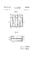
FIG. 9 is a top plan view of several primary packages according to the embodiment of FIG. 1, packed together in a secondary package of this invention, with the top of the secondary package removed for convenience in viewing.
FIG. 10 is a view partly in section and partly in elevation taken along the line of 1010 of FIG. 9 and showing the cover of the secondary container in phantom.
Referring to FIGS. 1-8 of the drawings, there is shown a primary package according to this invention which comprises a frangible tube 11 closed at the bottom and having a neck 12 defining an open mouth 13 at the top. The top end of the tube 11 is closed by a resilient cap 14, having a plugging section 15 which fits tightly into the mouth 13 of the tube. The tube contains a sterile surgical suture 16 wrapped around a reel 17 of sterilizable sheet material having slits 18 therein to hold the suture on the reel. The neck 12 of the tube is reduced somewhat in diameter from the body 19 of the tube and presents a rim 21 of increased thickness immediately surrounding the mouth of the tube. Thus, a shallow annular groove 22 is provided between the rim 21 and the body 19 of the tube.
The plugging section 15 of the cap is in the form of a hollow cylinder open at the bottom and comprises a cylindrical wall 23 which is radially deformable inwardly from its natural position to allow the plugging section to adapt easily to and fit tightly within the mouth 13 of the tube. The cap 14 further comprises a cylindrical resilient skirt 25 attached to the plugging section of the cap by -a pivot section 26 molded integral therewith. The skirt 25 is invertible from a first at-rest position extending axially away from the plugging section 15, as shown in FIGS. 6-8, to a second position depending from the pivot section 26 and axially overlapping the neck of the tube, as shown in FIGS. 15. In its depending position, the skirt 25 grips the neck of the tube, particularly the outside surface of the rim 21 of the neck, immediately surrounding the mouth 13 of the container. To assure that positive gripping action occurs between the skirt 25 and the rim 21, the normal (undistended) inside diameter of the skirt in its depending position is less than the outside diameter of the rim 21. Thus, a double seal is provided in the container of this embodiment. The plugging section 15 forms a seal with the inside surface of the mouth 13, and the skirt 25 in its depend-ing position forms a seal with the outside surface of the rim 21 surrounding the mouth.
A tab 27 is molded integral with the skirt 25 of the cap to facilitate inverting the cap from its depending position to the extended position thereof, shown in FIGS. 68. This may be accomplished merely by pulling upwardly on the tab, as illustrated by the. arrows in FIGS. and 6.
To hold the cap in position on the neck 12 of the tube and to assure that the container is not tampered with or assumed to be sterile after it has been open and reclosed, a safety seal is provided in the form of a sleeve 28 of film-like material sealed around the lower edge of the skirt 25 in its depending position and over a portion of the tab 27, as shown most clearly in FIGS. 1-5. The sleeve 28 grips the bottom edge of the skirt 25 and pulls it into the annular groove 22 on the neck of the tube, thus assuring that the skirt is held tightly against the outer surface of the rim 2 1. In addition, the safety sleeve 28, itself, is now necked in, or reduced in diameter slightly, so that it cannot possibly be removed from the package by sliding it over the cap 14. This assures that the package can only be opened by breaking the safety sleeve 28, thereby giving a clear indication of whether or not it has been previously opened or tampered with. Preferably, the sleeve 28 is weakened in the area of the tab 27, such as by lines of perforations 29 at each side of the tab, so that the sleeve may be torn and removed easily and the skirt inverted when the tab is pulled upward against the sleeve.
In operation, the contents of the tube 11, preferably already in a reasonably sterile condition, are inserted in the tube and the tube and contents are then sterilized together to assure that the interior and all sealed-off portions of the container are sterilized. There are various ways this may be accomplished. For instance, if the tube is to be packaged wet, a sterilizing fluid such as a small amount of ethylene oxide in alcohol may be inserted in the tube with the contents, and the cap itself may be dipped in the same fluid prior to positioning it on the tube. The safety seal then is applied tightly around the lower edge of the skirt after the skirt has been snapped over the neck of the tube. The sterilizing fluid inside the tube 1 1 then sterilizes the inside surface of the tube V and its contents.
If on the other hand, the contents of the tube 11 are to be packaged dry, a wicking thread, not shown, may be arranged between the cap 14 and the neck of the tube so that after the cap is in position on the tube, the inside surface of the container and its contents may be sterilized by exposing the package to an atmosphere of ethylene oxide gas under suflicient pressure to cause the gas to enter the tube along the wick. After a sufficient sterilizing period, the wick is withdrawn from the tube and the safety seal 28 is applied to assure that sterility is maintained.
When it is desired to use the contents of the package, the exposed end of the tab 27 is gripped and pulled upwardly as shown in FIG. 5 to cause the safety seal 28 to tear through the perforations 29, and invert the skirt 25 of the cap, all in one upward motion of the tab. When the cap is inverted it may be removed easily from the tube by the fingers holding the tab without the necessity or likelihood of contacting the rim of the package. One finger may conveniently be placed within the cup, formed by the extended skirt 25, for this purpose.
The resilient cap 14 of the package of this invention may be formed from any suitable resilient material which will not contaminate the contents of the container and 4. which is capable of accomplishing the objects of the invention in the form indicated. Natural rubber has been found suitable for this purpose. Similarly, the safety seal sleeve 28 may be formed from any suitable material, such as cellulose film sold by E. I. du Pont de Nemours & Co. of Delaware, under the trademark Cel-O-Seal.
FIGS. 9-10 illustrate an embodiment of this invention wherein a plurality of primary packages, or tubes 11, according to the embodiment of FIG. 1, ten tubes to be exact, are packed together in a secondary container, or enclosure, in the form of a cardboard box comprising a rectangular bottom section 31 and a corresponding telescoping rectangular lid 32. The bottom section 31 of the box comprises opposed side walls 33 and opposed end walls 34, respectively spaced to accommodate the length of the tubes and the combined widths thereof. In the embodiment of FIG. 1, the outside diameter of the cap 14 in the second, or overlapping, position of the skirt 25, is greater than the overall outside diameter of the tube, itself. Thus, when a plurality of the containers of FIG, 1 are packaged together, as shown in FIGS. 9 and 10, with the containers arranged in parallel alignment with one another in such a way that the caps 14 of adjacent containers are located at opposite ends of the box and in contact with the tubes 11 of one another, the tubes themselves are held firmly in position in spaced relation from one another. In other words, each tube 11, be it formed of glass or some other frangible material, is only in contact with the resilient rubber caps 14 of adjacent tubes and, at the end of each row, with one side of the box itself; and cannot contact or rattle against the other tubes during shipment or handling. Thus, a shock-proof package is provided wherein the frangible tubes are prevented from cracking or breaking.
Having now described the invention in specific detail and exemplified the manner in which it may be carried into practice, it will be readily apparent to those skilled in the art that innumerable variations, applications, modifications and extensions of the basic principles involved may be made without departing from its spirit or scope.
Wherefore I claim:
1. An .interiorly sterilized package comprising a tube presenting a cylindrical neck at one end of the package, said neck having an open mouth and a cylinder-ical outside surface immediately surrounding said mouth, sterile contents inside said tube; a resilient cap closing said mouth; said cap comprising a plugging section fitting tightly into the mouth of the neck, a substantially cylindrical and resilient skirt, and a pivot section connecting one edge of said skirt with said plugging section, said skirt being invertible from a first at-rest position extending axially away from said plugging section beyond said neck to a second position depending from said pivot section and axially overlapping the neck of the tube in gripping contact with said neck over and beyond the cylindrical outside surface thereof and all around said cylindrical surface to maintain said surface sterile; and a safety sleeve sealed around the lower edge of the skirt and overlapping the surface of said tube below the skirt in the second position of the skirt to hold the skirt in this position and prevent the skirt from being inverted without tearing the sleeve; said resilient cap further com-prising a pull tab integral with and depending from said resilient skirt to a position below the lower edge of said sleeve in the second position of the skirt for simultaneously tearing the safety sleeve and inverting the skirt by pulling upward on the tab; said plugging section sealing off the mouth of said tube, and said skirt in its second position covering said neck around its cylindrical mouth to assure that the contents of the package are maintained sterile prior to removal of the cap from said tube and that a sterile zone is provided surrounding said mouth to avoid contaminating the sterile contents of the package upon removal of said contents from the tube, and said 'safety sleeve assuring that the sterile zone is maintained and providing a tamper proof featu-re since the skirt cannot be inverted to remove the cap without tearing the sleeve, whereby the package may be opened easily merely by pulling on the tab to simultaneously tear the safety sleeve and invert the skirt to .allow removal of the cap from the tube.
2. A sterile package according to claim 1, wherein the plugging section is in the form of a hollow cylinder open at the bottom and comprises a cylindrical wall which is radially deformable to allow the plugging section to adapt to and fit tightly within said mouth.
3. A sterile package according to claim 1, where the safety sleeve is weakened in the area of the tab so that the sleeve may be torn and removed easily and the skirt inverted by pulling the tab upward against the sleeve.
4. A sterile package according to claim 1, wherein the safety sleeve constricts the ski-rt and has an inner diameter less than the outside diameter of the cap between the sleeve and the top end of the cap.
References Cited by the Examiner UNITED STATES PATENTS 2,074,477 3/1937 Kondolf 206-65 2,261,875 11/1941 Dunn 2154s 2,643,764 6/1953 Riall 206-633 2,801,741 8/1957 Harknessetal 206 63.3 10 3,074,578 1/1963 Hester 215 41 FOREIGN PATENTS 568,892 4/ 1945 Great Britain.
15 THERON E. CONDON, Primary Examiner.
GEORGE O. RALSTON, Examiner.
Claims (1)
1. AN INTERIORLY STERILIZED PACKAGE COMPRISING A TUBE PRESENTING A CYLINDRICAL NECK AT ONE END OF THE PACKAGE, SAID NECK HAVING AN OPEN MOUTH AND A CYLINDRICAL OUTSIDE SURFACE IMMEDIATELY SURROUNDING SAID MOUTH, STERILE CONTENTS INSIDE SAID TUBE; A RESILIENT CAP CLOSING SAID MOUTH; SAID CAP COMPRISING A PLUGGING SECTION FITTING TIGHTLY INTO THE MOUTH OF THE NECK, A SUBSTANTIALLY CYLINDRICAL AND RESILIENT SKIRT, AND A PIVOT SECTION CONNECTING ONE EDGE OF SAID SKIRT WITH SAID PLUGGING SECTION, SAID SKIRT BEING INVERTIBLE FROM A FIRST AT-REST POSITION EXTENDING AXIALLY AWAY FROM SAID PLUGGING SECTION BEYOND SAID NECK TO A SECOND POSITION DEPENDING FROM SAID PIVOT SECTION AND AXIALLY OVERLAPPING THE NECK OF THE TUBE IN GRIPPING CONTACT WITH SAID NECK OVER AND BEYOND THE CYLINDRICAL OUTSIDE SURFACE THEREOF AND ALL AROUND SAID CYLINDRICAL SURFACE TO MAINTAIN SAID SURFACE STERILE; AND A SAFETY SLEEVE SEALED AROUND THE LOWER EDGE OF THE SKIRT AND OVERLAPPING THE SURFACE OF SAID TUBE BELOW THE SKIRT IN THE SECOND POSITION OF THE SKIRT TO HOLD THE SKIRT IN THIS POSITION AND PREVENT THE SKIRT FROM BEING INVERTED WITHOUT TEARING THE SLEEVE; SAID RESILIENT CAP FURTHER COMPRISING A PULL TAB INTEGRAL WITH AND DEPENDING FROM SAID RESILIENT SKIRT TO A POSITION BELOW THE LOWER EDGE OF SAID SLEEVE IN THE SECOND POSITION OF THE SKIRT FOR SIMULTANEOUSLY TEARING THE SAFETY SLEEVE AND INVERTING THE SKIRT BY PULLING UPWARD ON THE TAB; SAID PLUGGING SECTION SEALING OFF THE MOUTH OF SAID TUBE, AND SAID SKIRT IN ITS SECOND POSITION COVERING SAID NECK AROUND ITS CYLINDRICAL MOUTH TO ASSURE THAT THE CONTENTS OF THE PACKAGE ARE MAINTAINED STERILE PRIOR TO REMOVAL OF THE CAP FROM SAID TUBE AND THAT A STERILE ZONE IS PROVIDED SURROUNDING SAID MOUTH TO AVOID CONTAMINATING THE STERILE CONTENTS OF THE PACKAGE UPON REMOVAL OF SAID CONTENTS FROM THE TUBE, AND SAID SAFETY SLEEVE ASSURING THAT THE STERILE ZONE IS MAINTAINED AND PROVIDING A TAMPER PROOF FEATURE SINCE THE SKIRT CANNOT BE INVERTED TO REMOVE THE CAP WITHOUT TEARING THE SLEEVE, WHEREBY THE PACKAGE MAY BE OPENED EASILY MERELY BY PULLING ON THE TAB TO SIMULTANEOUSLY TEAR THE SAFETY SLEEVE AND INVERT THE SKIRT TO ALLOW REMOVAL OF THE CAP FROM THE TUBE.
Priority Applications (2)
| Application Number | Priority Date | Filing Date | Title |
|---|---|---|---|
| US367844A US3241663A (en) | 1964-05-15 | 1964-05-15 | Surgical package |
| BE663751D BE663751A (en) | 1964-05-15 | 1965-05-11 |
Applications Claiming Priority (1)
| Application Number | Priority Date | Filing Date | Title |
|---|---|---|---|
| US367844A US3241663A (en) | 1964-05-15 | 1964-05-15 | Surgical package |
Publications (1)
| Publication Number | Publication Date |
|---|---|
| US3241663A true US3241663A (en) | 1966-03-22 |
Family
ID=23448867
Family Applications (1)
| Application Number | Title | Priority Date | Filing Date |
|---|---|---|---|
| US367844A Expired - Lifetime US3241663A (en) | 1964-05-15 | 1964-05-15 | Surgical package |
Country Status (2)
| Country | Link |
|---|---|
| US (1) | US3241663A (en) |
| BE (1) | BE663751A (en) |
Cited By (8)
| Publication number | Priority date | Publication date | Assignee | Title |
|---|---|---|---|---|
| US3989045A (en) * | 1972-09-29 | 1976-11-02 | Eck William F Van | Hypodermic syringe |
| US4094429A (en) * | 1976-07-26 | 1978-06-13 | Urbin Matthew C | Stopper for test tube, and the like |
| US4573980A (en) * | 1983-09-16 | 1986-03-04 | Baxter Travenol Laboratories, Inc. | Port protector |
| US5088995A (en) * | 1990-06-22 | 1992-02-18 | Baxter International Inc. | Port and closure assembly including a resealing injection site for a container |
| US20050155659A1 (en) * | 2004-01-20 | 2005-07-21 | Rick Rahimzadeh | Reversible dual size plumbing end cap |
| US20070023434A1 (en) * | 2003-08-27 | 2007-02-01 | Sang-Kee Kim | Container cover |
| US8864725B2 (en) | 2009-03-17 | 2014-10-21 | Baxter Corporation Englewood | Hazardous drug handling system, apparatus and method |
| US11426856B2 (en) * | 2018-08-03 | 2022-08-30 | The Stanley Works Israel Ltd. | Convertible sawhorse and worktable |
Citations (6)
| Publication number | Priority date | Publication date | Assignee | Title |
|---|---|---|---|---|
| US2074477A (en) * | 1932-09-01 | 1937-03-23 | Southern Kraft Corp | Carton and blank for forming the same |
| US2261875A (en) * | 1937-06-03 | 1941-11-04 | Sylvania Ind Corp | Article and method of making the same |
| GB568892A (en) * | 1943-04-05 | 1945-04-25 | William Simon Freeman | Improvements in or relating to closures for containers |
| US2643764A (en) * | 1949-05-13 | 1953-06-30 | Davis & Geck Inc | Rectangular package of surgical articles in sterilizing liquid |
| US2801741A (en) * | 1954-08-16 | 1957-08-06 | C Dewitt Lukens Surgical Mfg C | Sterile container and ligature package |
| US3074578A (en) * | 1956-12-26 | 1963-01-22 | Dwight H Hester | Container closures |
-
1964
- 1964-05-15 US US367844A patent/US3241663A/en not_active Expired - Lifetime
-
1965
- 1965-05-11 BE BE663751D patent/BE663751A/xx unknown
Patent Citations (6)
| Publication number | Priority date | Publication date | Assignee | Title |
|---|---|---|---|---|
| US2074477A (en) * | 1932-09-01 | 1937-03-23 | Southern Kraft Corp | Carton and blank for forming the same |
| US2261875A (en) * | 1937-06-03 | 1941-11-04 | Sylvania Ind Corp | Article and method of making the same |
| GB568892A (en) * | 1943-04-05 | 1945-04-25 | William Simon Freeman | Improvements in or relating to closures for containers |
| US2643764A (en) * | 1949-05-13 | 1953-06-30 | Davis & Geck Inc | Rectangular package of surgical articles in sterilizing liquid |
| US2801741A (en) * | 1954-08-16 | 1957-08-06 | C Dewitt Lukens Surgical Mfg C | Sterile container and ligature package |
| US3074578A (en) * | 1956-12-26 | 1963-01-22 | Dwight H Hester | Container closures |
Cited By (10)
| Publication number | Priority date | Publication date | Assignee | Title |
|---|---|---|---|---|
| US3989045A (en) * | 1972-09-29 | 1976-11-02 | Eck William F Van | Hypodermic syringe |
| US4094429A (en) * | 1976-07-26 | 1978-06-13 | Urbin Matthew C | Stopper for test tube, and the like |
| US4573980A (en) * | 1983-09-16 | 1986-03-04 | Baxter Travenol Laboratories, Inc. | Port protector |
| US5088995A (en) * | 1990-06-22 | 1992-02-18 | Baxter International Inc. | Port and closure assembly including a resealing injection site for a container |
| US20070023434A1 (en) * | 2003-08-27 | 2007-02-01 | Sang-Kee Kim | Container cover |
| US8678212B2 (en) * | 2003-08-27 | 2014-03-25 | Sunrise Kitchen Co., Ltd. | Container and container cover for sealing the container opening |
| US20050155659A1 (en) * | 2004-01-20 | 2005-07-21 | Rick Rahimzadeh | Reversible dual size plumbing end cap |
| US6935380B2 (en) * | 2004-01-20 | 2005-08-30 | California Plumbing Products, Inc. | Reversible dual size plumbing end cap |
| US8864725B2 (en) | 2009-03-17 | 2014-10-21 | Baxter Corporation Englewood | Hazardous drug handling system, apparatus and method |
| US11426856B2 (en) * | 2018-08-03 | 2022-08-30 | The Stanley Works Israel Ltd. | Convertible sawhorse and worktable |
Also Published As
| Publication number | Publication date |
|---|---|
| BE663751A (en) | 1965-11-12 |
Similar Documents
| Publication | Publication Date | Title |
|---|---|---|
| US2771218A (en) | Closure assembly | |
| JP3565920B2 (en) | Sterile packaging | |
| US3301393A (en) | Suture package | |
| US3826059A (en) | Method of packaging radioactive materials | |
| US3403776A (en) | Sterile surgical package | |
| US3342319A (en) | Rigid tubular syringe package | |
| JPH10503151A (en) | Cartonless packaging system | |
| US3203545A (en) | Sterile article package and method of making the same | |
| US4253459A (en) | Additive transfer unit with stabilized sealing means | |
| US3241663A (en) | Surgical package | |
| CA2178771C (en) | Prefill syringe | |
| GB1580307A (en) | Airtight container | |
| US2855933A (en) | Fluid receptacle | |
| US3770155A (en) | Dually sealable, non-leaking vial for shipping radioactive materials | |
| US20210077242A1 (en) | Protective container for sterilized medical implants | |
| JPH03503501A (en) | Closure and spout assembly | |
| US4200100A (en) | Additive transfer unit with piercing member having a penetratable protective tip | |
| US2965225A (en) | Suture package | |
| US3096904A (en) | Sealed plastic containers | |
| US2628910A (en) | Methods and devices for merchandising and dispensing liquid infant food | |
| US4562932A (en) | Cap closure for a container with pharmaceutical contents | |
| US1344664A (en) | Packaging pulverulent materials | |
| US2549039A (en) | Surgical package | |
| US3443711A (en) | Vacuum-indicating two-part tamper-proof closure and combination | |
| GB2193193A (en) | Closure for a container |