US3095926A - Apparatus for recovering objects in a well - Google Patents
Apparatus for recovering objects in a well Download PDFInfo
- Publication number
- US3095926A US3095926A US758829A US75882958A US3095926A US 3095926 A US3095926 A US 3095926A US 758829 A US758829 A US 758829A US 75882958 A US75882958 A US 75882958A US 3095926 A US3095926 A US 3095926A
- Authority
- US
- United States
- Prior art keywords
- mandrel
- washover pipe
- slips
- well
- slip
- Prior art date
- Legal status (The legal status is an assumption and is not a legal conclusion. Google has not performed a legal analysis and makes no representation as to the accuracy of the status listed.)
- Expired - Lifetime
Links
- 239000012530 fluid Substances 0.000 claims description 23
- 230000006872 improvement Effects 0.000 claims description 8
- 238000011084 recovery Methods 0.000 claims description 6
- 241000251468 Actinopterygii Species 0.000 description 45
- 238000005553 drilling Methods 0.000 description 7
- 238000005520 cutting process Methods 0.000 description 4
- 230000000881 depressing effect Effects 0.000 description 4
- 238000004891 communication Methods 0.000 description 3
- 238000010276 construction Methods 0.000 description 3
- 239000000463 material Substances 0.000 description 3
- 238000010008 shearing Methods 0.000 description 3
- 230000035882 stress Effects 0.000 description 3
- 230000006835 compression Effects 0.000 description 2
- 238000007906 compression Methods 0.000 description 2
- 230000004048 modification Effects 0.000 description 2
- 238000012986 modification Methods 0.000 description 2
- 238000005406 washing Methods 0.000 description 2
- 230000009471 action Effects 0.000 description 1
- 230000032683 aging Effects 0.000 description 1
- 230000000712 assembly Effects 0.000 description 1
- 238000000429 assembly Methods 0.000 description 1
- 150000001768 cations Chemical class 0.000 description 1
- 230000000295 complement effect Effects 0.000 description 1
- 238000004519 manufacturing process Methods 0.000 description 1
- 239000002184 metal Substances 0.000 description 1
- 238000012856 packing Methods 0.000 description 1
- 239000003208 petroleum Substances 0.000 description 1
- 230000008707 rearrangement Effects 0.000 description 1
Images


Classifications
-
- E—FIXED CONSTRUCTIONS
- E21—EARTH DRILLING; MINING
- E21B—EARTH DRILLING, e.g. DEEP DRILLING; OBTAINING OIL, GAS, WATER, SOLUBLE OR MELTABLE MATERIALS OR A SLURRY OF MINERALS FROM WELLS
- E21B31/00—Fishing for or freeing objects in boreholes or wells
- E21B31/12—Grappling tools, e.g. tongs or grabs
- E21B31/16—Grappling tools, e.g. tongs or grabs combined with cutting or destroying means
-
- E—FIXED CONSTRUCTIONS
- E21—EARTH DRILLING; MINING
- E21B—EARTH DRILLING, e.g. DEEP DRILLING; OBTAINING OIL, GAS, WATER, SOLUBLE OR MELTABLE MATERIALS OR A SLURRY OF MINERALS FROM WELLS
- E21B29/00—Cutting or destroying pipes, packers, plugs, or wire lines, located in boreholes or wells, e.g. cutting of damaged pipes, of windows; Deforming of pipes in boreholes or wells; Reconditioning of well casings while in the ground
-
- E—FIXED CONSTRUCTIONS
- E21—EARTH DRILLING; MINING
- E21B—EARTH DRILLING, e.g. DEEP DRILLING; OBTAINING OIL, GAS, WATER, SOLUBLE OR MELTABLE MATERIALS OR A SLURRY OF MINERALS FROM WELLS
- E21B31/00—Fishing for or freeing objects in boreholes or wells
- E21B31/12—Grappling tools, e.g. tongs or grabs
- E21B31/20—Grappling tools, e.g. tongs or grabs gripping internally, e.g. fishing spears
Definitions
- Another object of the present invention is to provide such an apparatus including a mandrel within a washover pipe whereby longitudinal upward and downward forces and torque in either direction may be applied to the fish at any desired time and yet during any part of the operation the washover pipe may be freed from the mandrel for cutting over the fish and then re-engaged with the mandrel.
- a still further object of the present invention is to provide such an apparatus including a mandrel within a washover pipe with a wash passage within the mandrel whereby drilling fluid in the washover pipe is jetted into the vicinity of the lower end of the mandrel during the lowering of the apparatus into a well.
- a still further object of the present invention is to provide such a mandrel and washover pipe assembly which is exceedingly simple to construct, operate, and maintain and which is dependable in use.
- FIGURE 1 is a side view, partially sectional, of the apparatus being lowered into a cased well bore
- FIGURE 2 is a view similar to FIGURE 1 illustrating the apparatus after it has engaged the fish and the shearable connecting means between the mandrel and washover pipe has been sheared,
- FIGURE 3 is a View similar to FIGURE 1 illustrating the washover operation
- FIGURE 4 is a view similar to FIGURE 1 illustrating the removal of the apparatus and fish from the cased well bore
- FIGURE 5 is a view similar to FIGURE 1 illustrating the apparatus of the present invention in position for disengaging it from a fish that cannot be removed,
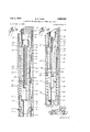
- FIGURE 6-A is an enlarged elevation, partially sectional, of the upper portion of the apparatus of the present invention, in position to be lowered into a well,
- FIGURE 6B is a continuation of FIGURE 6-A
- FIGURE 6-C is a continuation of FIGURE 6-B
- FIGURE 7 is an enlarged fragmentary view of the J-slot in-the mandrel
- FIGURE 8 is a view along the line 8-8 of FIGURE 6-A,
- FIGURE 9 is an enlarged sectional elevation of the catcher assembly of a modified form of invention with the catcher assembly in released position
- FIGURE 10 is a view similar to FIGURE 9 with the catcher assembly in engaged position.
- the invention includes the elongated washover pipe 10 adapted to be moved in a well, the elongated mandrel 12 loosely fitting within the washover pipe 16, and engaging means secured to the lower end of the mandrel 12 for engaging the stuck object in the well, such engaging means being here illustrated as the spear 14.
- the washover pipe 10 is made up of different sections threadedly connected together such as the sections 16, 18, and 20 respectively. Additional sections are secured above section 16, beginning at the threaded connection 22, to give sufficient length of washover pipe It) .to carry out the particular washover operation desired.
- a conventional cutting shoe 24 At the lower end of the washover pipe 10 is provided a conventional cutting shoe 24 here illustrated as being a roughened lower end of the washover pipe 10 of wear resistant metal. The foregoing construction is conventional and of itself does not constitute the present invention.
- the elongated mandrel 12 includes at its upper end, in the form illustrated in FIGURES 1 through 8, an enlarged diameter portion 26 closely but slidably fitted by an annular ring 28 made into the washover pipe 10.
- the mandrel 12 when in the position illustrated in the FIGURES 1 and 6-A through 6-B is releasably secured in position in the washover pipe 10 by the releasable connecting means of shear pins 32 passing through the washover pipe 10 into the enlarged diameter portion 26.
- the internal diameter or the washover pipe 1% at its annular ring 28 is slightly greater than the external diameter of the enlarged diameter portion 26 of the mandrel 12 and all other portions of the mandrel 12 and the spear 14 below the ring 28 so that when the pins 32 are sheared the washover pipe 10 may move downwardly with respect to the mandrel 12.
- a tapered shoulder 33 on the lower side of the ring 28 prevents the ring 28 from catching on shoulders on the mandrel 12 when the washover pipe 10 is moved downwardly with respect to the mandrel 12 as later explained.
- the mandrel 12 is made up of a plurality of sections including the J-sub 34 which carries the enlarged diameter portion 26, and the extension sub 36 threadedly secured to the lower end of the J-sub 34 (see FIGURE 6B).
- This extension sub 36 may be of any desired length to give the mandrel 12 the length desired for a purpose later herein explained.
- Threadedly secured to the lower end of the extension sub 36 is the drain sub 38 to the lower end of which is threadedly secured the safety joint 40 (see FIGURE 6-C).
- suitable packing such as the O-ring 30 is provided in the enlarged diameter portion 26 at the annular ring 28.
- the mandrel 12 carries a longitudinal fluid passageway from the upper end of the mandrel 12 to the drain sub 38 with fluid communication being established between the fluid passageway 42 and the exterior of the mandrel 12 at the port 44 so that drilling fiuid under pressure in the washover pipe 111 above the mandrel 12 will be forced from the mandrel 12 in the proximity of the spear 14 regardless of the length of the extension sub 36.
- the safety joint 4% is provided in the event the spear 14 cannot be released from the fish 43 here illustrated as a packer lodged in the casing 45.
- the safety joint 40 here illustrated includes the pin member 46 threadedly secured at its upper end 48 to the drain sub 33. Below its upper end 48 the pin member 46 is reduced in diameter at the shoulder 49 to form the reduced diameter portion 56 which extends to the lower end of the pin member 46 and closely fits into the box member 52 forming the lower portion of the safety joint 40.
- J-slots 53 Formed in the reduced diameter portion 56 of the pin member 46 are a pair of J-slots 53, one only being shown, each including a first generally vertical slot 54 having an opening at the lower end of the pin member 46, a transverse slot 56 communicating with the upper end of the first vertical slot 54, and a second vertical slot 58 communicating with the transverse slot 56 and extending both above and below the transverse slot 56 with the second vertical slot 58 being closed at its upper and lower ends.
- lug 60 Slidably received in this J-slot 53 is the lug 60 carried by the box member 52 of the safety joint 40.
- the safety joint 40 is held in its assembled position as illustrated in FlGURE 6-C by shear pins 62 passing through the box and pin members 52 and 46 respectively.
- the pin member 46 When the safety joint 40 is to be operated, that is to separate the pin member 46 from the box member 52, the pin member 46 is pulled upwardly, as will be explained later, shearing the shear pins 62 allowing the pin member 46 to move upwardly until the lug 60 is at the lower end of the second vertical slot 58. The pin member 46 is then moved downwardly and torqued to left as viewed in FIGURE 6-C until the lug 60 is in line with the transverse slot 56 whereupon the pin member 46 is rotated until the first vertical slot 54 is in line with the lug 6t Thereupon upward movement of the pin member 46 will allow the pin member 46 to be removed from the box member 52. by pulling the vertical slot 54 past the lug 60.
- the engaging means secured to the lower end of the mandrel 12 for engaging the fish may be of any type that engages the fish upon a downward movement, an upward movement, a torque, or any combination thereof and which is released upon a downward movement or a torque or both.
- the particular engaging means here illustrated is a spear 14 which is described in Patent No. 1,776,989
- this particular spear 14 has an upper body 63 threadedly secured to the lower end of the mandrel 12 at the safety joint 40.
- a spear mandrel 65 on which is slidably mounted a cage 66 provided with slips 64 expanded by the slip expander 68 near the lower end of the spear mandrel 65.
- a bowspring 70 provides friction between the cage 66 and the internal wall of a fish 43.
- FIGURES 6A and 7 there is illustrated the means by which the spear 14 may be torqued in either direction and stressed or moved longitudinally in either direction.
- Formed in the enlarged portion 27 of the mandrel 12 and below its upper end are a pair of J-slots 76 each provided with a first vertical slot 78 opened at the lower end of the enlarged portion 27, a transverse slot 89 communicating with the first vertical slot 78, and a second vertical slot 32 parallel to the first vertical slot 78 and communicating with the transverse leg 89 with the second vertical slot 82 being closed at its lower end 64.
- Formed in the interior wall of the washover pipe 16 are a pair of inwardly projecting lugs 36 adapted to be slidably received in the J-slots 76. How- 'of cuttings and other material.
- the internal diameter of the washover pipe 10 between these lugs 86 is less than the external diameter of the enlarged portion 27 of the mandrel 10 so that downward movement of the enlarged portion 27 of the mandrel 12 past the lugs 86 is permissible only to the extent that the lugs 86 move within the J-slots 76.
- the desired amount of washover pipe 19 below the enlarged diameter portion 26 of the mandrel 12 is lowered into the well with the upper end of the last section being held above the surface of the earth.
- the spear 14, the safety joint 40, the drain sub 38 and the desired length of the extension sub 36 are made up and this part of the mandrel 12 is lowered into the washover pipe 113 until the upper end of the extension sub 36 extends slightly above the upper end of the washover pipe 10 projecting from the well.
- the J-sub of the mandrel 12. is placed in the next section of washover pipe 10, il-
- FIGURE 6-A illustrating in FIGURE 6-A as section 16, in which the annular ring 28 is located.
- the shear pins 32 are inserted to releasably secure the J-sub 34 to the section 16 of the washover pipe 11
- the section 16 of the washover pipe 151 with the J-sub 34 of the mandrel 12 in it is lifted into position over the upper end of the extension sub 36 extending upwardly from the portion of the washover pipe 11) extending from the well and the J-sub 34 is then threadedly secured to the extension sub 36.
- the section 16 of the washover pipe 10 is then threadedly secured to the upper end of the washover pipe 10 extending from the well and the washover pipe 10 lowered into the well with additional sections being added to make up the necessary length of washover pipe 10.
- the upper end of the washover pipe 11 (not shown) is then connected to an operating string of pipe and lowered into the well in the position shown in FIGURE 1.
- the washover pipe 10 is freed from the mandrel 12 for washing over operations.
- the washover pipe 10 is then rotated and lowered by the operating string of pipe cutting downwardly around the fish 43 as illustrated in FIGURE 3 until the fish 43 is freed and can be removed.
- a length of extension sub 36 is chosen so that as the washover pipe 10 lowers after the mandrel 12 has been fixed in the fish 43 the lugs 86 will not reach the fish 43 before it is freed.
- the lugs 86 should not be in line with the bottom end of the first vertical slots 78 of the J-slots 76 the lugs 86 will bear against the shoulder 87 at the lower end of the enlarged diameter portion 26 of the mandrel 12 and support the mandrel 12 as the washover pipe 10 is removed from the well.
- the mandrel 12, and the spear 14 may be removed from the well by manipulation of the washover pipe 10 by the string of operating pipe so that the lugs 86 are moved upwardly in the first vertical slots 78 of the J-slots 76 as is shown in FIGURE 4, rotating the washover pipe 10 so that the lugs 86 move through the transverse legs 80, and then moving the washover pipe 10 downwardly until the lugs 86 are at the lower end 84 of the second vertical slots 32 as illustrated in FIGURE 5.
- FIGURES 9 and 10* there is illustrated a modification in which the mandrel 12a includes at its upper end a catcher assembly adapted to releasably secure the mandrel 12a to the washover pipe 10 when the fish 43 is freed without the necessity of raising the mandrel to the position illustrated in FIGURE 4.
- the form of apparatus is identical to that illustrated in FIGURES 1 through 8.
- the mandrel 12-a includes an elongated slip expander stem threadedly secured at 101 in axial alignment to a stem sub 102 which is in turn threadedly secured at 103 to the enlarged diameter portion 26-01 of the mandrel 12a.
- the slip expander stem 100 is provided with an axial cylinder 104 normally open at its upper end to the interior of the washover pipe 10 as illustrated in FIGURE 10.
- the fluid passageway 42-11 extending through the mandrel 12a communicates with the lower end of the cylinder 104 through the enlarged counterbored portion 106.
- a preferably cup shaped piston 108 Slidably mounted in the cylinder 104 is a preferably cup shaped piston 108 made integral with the lower end of which is a hollow piston rod 110 slidably received in the counterbored portion 106 of the fluid passageway 42a.
- the mandrel 12-a is internally threaded at to hold the externally threaded piston depressing plug 107, shown in dotted lines, while the apparatus is being assembled as will be later explained. During use of the apparatus the plug 107 is removed. Downward movement of this piston 100 is limited by contact of the lower surface 112 of the piston 108 with the lower end 114 of the cylinder 104.
- a port 116 is provided at the lower end of the cylinder 104 for escape of fluid below the piston 108.
- the upper end of the slip expander stern 100 has an external diameter loosely fitting the interior of the washover pipe 10. Below the cylinder 1% the remainder of slip expander stem 100 is provided with a reduced diamgage the washover pipe 10 and each is provided on its underneath surface with a tapered portion 134 complementary to and adapted to ride over the slip expander 122.
- the slips 128 are retracted in the position illustrated in FIGURE 9 when not in contact with the slip expander 122 and do not engage the washover pipe 10 until the slip assembly 124 is moved upwardly causing the slipheads 130 to ride over the slip expander r122 moving the slipheads 130 outwardly into engagement with the washover pipe 10 as illustrated in FIGURE 10.
- the slip assembly 124 and slip expander 122 are of conventional construction and no further description of them is necessary.
- the upper end of the stem sub 192 forms an upwardly facing shoulder 14% and the lower end of the collar 126 forms a downwardly facing shoulder 142 between which shoulders and around the slip expander stem 1% is a compression coil spring 144 urging the slip assembly 124 upwardly toward the slip expander 122 thus tending to set the slips 128 as illustrated in FIGURE 1-0.
- the J-sub 34 and all parts of the mandrel 12-4: below it and the spear 14 are secured to gether and into the washover pipe as previously described.
- the slip expander stem 10! is then secured to the stem sub 102 and the stem sub 1&2 is then threadedly secured to the enlarged diameter portion 26-;1 which is near the upper end of the section 16 of the washover pipe v10 so that the slip heads 13% are above the section 16 of the washover pipe 10. Because the coil spring 144 will be holding the slip assembly 1214- in an upward position expanding the slips 126 the next section of the washover pipe 10 will not pass over the slipheads 130.
- the piston depressing plug 107 is engaged in the threads 105 at the top of the cylinder 1% and screwed downwardly depressing the piston 108 and retracting the slips 128.
- a short section 22 of washover pipe 10 is lowered over the upper end of the mandrel 12-a and made up to the section 16.
- the depressing plug 107 is then removed freeing the piston 1G8 causing the slips 128 to set.
- the washover pipe 10 is lowered into the well with additional sections being added to makeup the necessary length.
- the upper end of the washover pipe (not shown) is then connected to an operating string of pipe and lowered into the well.
- shear pins 32 While it is preferable to use shear pins 32 with the modified mandrel 12-11 these shear pins may be omitted. If this is done the slips 128 are allowed to set and releasably secure the mandrel 12-a to the washover pipe 10 during lowering of the apparatus into the well and the securing of the spear 14 to the fish 43. This is done by keeping the drilling fluid pressure on the piston 10S below that necessary to compress the spring 144. When the spear 14 is engaged in the fish 43 the slips 1-28 are released by increasing the pump pressure and setting a 5% down on the washover pipe allowing the washover operations to take place'as previously described.
- an elongated washover pipe adapted to be moved in a well
- an elongated mandrel in said washover pipe engaging means connected to the lower end of the mandrel adapted to engage the object in the well
- said mandrel including an enlarged diameter portion
- releasable connecting means releasably securing the mandrel in the washover pipe
- a first J-slot in the enlarged diameter portion of the mandrel below its upper end
- a lug on the inner wall of the washover pipe adapted to be slidably received in said first J-slot
- a second J-slot in the mandrel below the enlarged diameter portion of said mandrel and a lug connected to said engaging means and adapted to be slidably received in said second .l-slot
- shearable means releasably securing the engaging means to the mandrel.
- an apparatus for recovering lodged objects in a well having an elongated washover pipe adapted to be moved in a well, an elongated mandrel in said washover pipe, said mandrel including an enlarged diameter portion, and engaging means connected to the lower end of the mandrel adapted to engage the object in the well, said engaging means having upwardly directed slips so constructed and arranged so as to engage said object while under an upwards stress, the improvement comprising, a first J-slot in the enlarged diameter portion of the mandrel below its upper end, a first lug on the inner wall of the washover pipe adapted to be slidably received in said J-slot, first shearable means releasably securing the mandrel in the washover pipe, a second J-slot in the mandrel below the enlarged diameter portion, a second lug connected to the engaging means and adapted to be slidably received in said second J-slot, and a second shearable means releas
- an apparatus for recovery of objects in a well bore said apparatus including a washover pipe, a mandrel movable in the washover pipe, and engaging means connected to the lower end of the mandrel adapted to engage the object in the well, the improvement comprising, an open ended cylinder at the upper end of the mandrel, a piston slidably mounted in the cylinder, a slip assembly slidably secured to the mandrel, said slip assembly including slips, said mandrel including a vertical slot adjacent the slip assembly, said 'mandrel being tapered adjacent its upper end to form a slip expander adapted to expand the slips into engagement with the washover pipe upon relative movement of the slips towards the slip expander and to release the slips upon relative movement of the slips away from the slip expander, spring means urging the slip assembly toward the slip expander, a rigid connection secured between the piston and the slip assembly through the vertical slot whereby on appli cation of fluid pressure on the piston the slip assembly is moved in one direction retracting the
- said apparatus including a washover pipe, a mandrel movable in the washover pipe, and en aging means con nected to the lower end of the mandrel adapted to engage the object in the welLthe improvement comprising, an open ended cylinder at the upper end of the mandrel, a piston slidably mounted in the cylinder, a slip assembly slidably secured to the mandrel, said slip assembly ineluding slips, said mandrel including an opening in communication with said open ended cylinder and including a vertical slot adjacent the slip assembly, said mandrel being tapered adjacent its upper end to form a slip expander adapted to expand the slips into engagement with the washover pipe upon relative movement of the slips towards the slip expander and to release the slips upon relative movement of the slips away from the slip expander, spring means urging the slip assembly toward the slip expander, a piston rod secured to the piston and slidably movable in the mand
- An apparatus for recovery of objects lodged in the well bore comprising, an elongated washover pipe adapted to be moved in the well, an elongated mandrel in said washover pipe, said mandrel including an enlarged diameter portion, shearable means securing the mandrel in the washover pipe, at least one J-slot in the enlarged diameter portion of the mandrel below its upper end, said J-slot including a first vertical slot open at the lower end of the enlarged diameter portion, a transverse slot communicating with the first vertical slot, and a second vertical slot communicating with the transverse slot and enclosed at its lower end, an open ended cylinder at the upper end of the mandrel, a piston slidably received in the cylinder, a slip assembly slidably secured to the mandrel, said slip assembly including slips, said mandrel being tapered adjacent its upper end to form a slip expander and adapted to expand the slips into engagement with the washover pipe upon relative movement of the slips toward the slip expand
- the invention of claim 6 including :a fluid passageway extending longitudinally through the mandrel, the piston rod, and the .piston communicating with the washover pipe at the upper end of the mandrel and approximate the lower end of the mandrel.
Description
y 2, 1963 G. E. RUSH 3,095,926
APPARATUS FOR RECOVERING OBJECTS IN A WELL Filed Sept. 3, 1958 5 Sheets-Sheet 1 f. Hus/7 /ZZZ K ,wmw
ATTOR/VfYJ July 2, 1963 G. E. RUSH 3,095,926
APPARATUS FOR RECOVERING OBJECTS IN A WELL Filed Sept. 3, 1958 5 Sheets-Sheet 4 f I/ZM E f Gear 6 E. RuJ/z 7 INVENTQ.
July 2, 1963 G. E. RUSH 3,095,926
APPARATUS FOR RECOVERING OBJECTS IN A WELL Gear 6* E. fPuJ/i y INVENTOR.
ATTORNEYS United States Patent Ofitice 3,0fi5,926 Patented July 2, 1963 3,11%,926 APPARATUS FGR RECOVERING OBJECTS) IN A WELL George E. Rush, Odessa, Tex assignor to Houston Oil Field Material Company, Inc. Houston, Tex a corporation of Delaware Filed Sept. 3, 1958, Ser. No. 758,829 7 Claims. (Cl. 166-55) This invention relates to an apparatus for recovering objects lodged in a well and more particularly to an apparatus by which the lodged object is engaged while being cut around to loosen it.
In the drilling of petroleum wells and during the production from such wells various pieces of pipe and other material occasionally become stuck in the well and have to be removed by what is commonly known in the trade as fishing operations with the stuck object commonly referred to as a fish. In one type of fishing operation a washover pipe of larger diameter than the stuck object is lowered to cut around the fish and free it so that the fish may be either removed by another apparatus lowered into the well to engage the freed fish or by a fish engaging means carried with the washover pipe. It is to an improved apparatus of the latter type that the present invention is directed.
It is a general object of the present invention to provide an apparatus for recovering objects in the well which apparatus will free the fish and remove it from the well without the necessity of separately removing any of the apparatus from the well, which allows an upward pull to be placed on the fish at any desired time, which is releasable from the stuck fish at any time, and which permits circulation of drilling fluid through the apparatus.
Another object of the present invention is to provide such an apparatus including a mandrel within a washover pipe whereby longitudinal upward and downward forces and torque in either direction may be applied to the fish at any desired time and yet during any part of the operation the washover pipe may be freed from the mandrel for cutting over the fish and then re-engaged with the mandrel.
A still further object of the present invention is to provide such an apparatus including a mandrel within a washover pipe with a wash passage within the mandrel whereby drilling fluid in the washover pipe is jetted into the vicinity of the lower end of the mandrel during the lowering of the apparatus into a well.
A still further object of the present invention is to provide such a mandrel and washover pipe assembly which is exceedingly simple to construct, operate, and maintain and which is dependable in use.
Other and further objects, features and advantages of the present invention will appear from the description of the presently preferred example, which is given for the purpose of disclosure and which is taken in conjunction with the accompanying drawings where like character references designate like parts throughout the several views, and where,
FIGURE 1 is a side view, partially sectional, of the apparatus being lowered into a cased well bore,
FIGURE 2 is a view similar to FIGURE 1 illustrating the apparatus after it has engaged the fish and the shearable connecting means between the mandrel and washover pipe has been sheared,
FIGURE 3 is a View similar to FIGURE 1 illustrating the washover operation,
FIGURE 4 is a view similar to FIGURE 1 illustrating the removal of the apparatus and fish from the cased well bore,
FIGURE 5 is a view similar to FIGURE 1 illustrating the apparatus of the present invention in position for disengaging it from a fish that cannot be removed,
FIGURE 6-A is an enlarged elevation, partially sectional, of the upper portion of the apparatus of the present invention, in position to be lowered into a well,
FIGURE 6B is a continuation of FIGURE 6-A,
FIGURE 6-C is a continuation of FIGURE 6-B,
FIGURE 7 is an enlarged fragmentary view of the J-slot in-the mandrel,
FIGURE 8 is a view along the line 8-8 of FIGURE 6-A,
FIGURE 9 is an enlarged sectional elevation of the catcher assembly of a modified form of invention with the catcher assembly in released position, and
FIGURE 10 is a view similar to FIGURE 9 with the catcher assembly in engaged position.
Referring now to the drawings, and particularly to FIGURE 1, the invention includes the elongated washover pipe 10 adapted to be moved in a well, the elongated mandrel 12 loosely fitting within the washover pipe 16, and engaging means secured to the lower end of the mandrel 12 for engaging the stuck object in the well, such engaging means being here illustrated as the spear 14.
Referring to FIGURES l and 6-A through 6-C the washover pipe 10 is made up of different sections threadedly connected together such as the sections 16, 18, and 20 respectively. Additional sections are secured above section 16, beginning at the threaded connection 22, to give sufficient length of washover pipe It) .to carry out the particular washover operation desired. At the lower end of the washover pipe 10 is provided a conventional cutting shoe 24 here illustrated as being a roughened lower end of the washover pipe 10 of wear resistant metal. The foregoing construction is conventional and of itself does not constitute the present invention.
The elongated mandrel 12 includes at its upper end, in the form illustrated in FIGURES 1 through 8, an enlarged diameter portion 26 closely but slidably fitted by an annular ring 28 made into the washover pipe 10. The mandrel 12 when in the position illustrated in the FIGURES 1 and 6-A through 6-B is releasably secured in position in the washover pipe 10 by the releasable connecting means of shear pins 32 passing through the washover pipe 10 into the enlarged diameter portion 26. The internal diameter or the washover pipe 1% at its annular ring 28 is slightly greater than the external diameter of the enlarged diameter portion 26 of the mandrel 12 and all other portions of the mandrel 12 and the spear 14 below the ring 28 so that when the pins 32 are sheared the washover pipe 10 may move downwardly with respect to the mandrel 12. A tapered shoulder 33 on the lower side of the ring 28 prevents the ring 28 from catching on shoulders on the mandrel 12 when the washover pipe 10 is moved downwardly with respect to the mandrel 12 as later explained. For ease of construction and adjustability of length the mandrel 12 is made up of a plurality of sections including the J-sub 34 which carries the enlarged diameter portion 26, and the extension sub 36 threadedly secured to the lower end of the J-sub 34 (see FIGURE 6B). This extension sub 36 may be of any desired length to give the mandrel 12 the length desired for a purpose later herein explained. Threadedly secured to the lower end of the extension sub 36 is the drain sub 38 to the lower end of which is threadedly secured the safety joint 40 (see FIGURE 6-C).
To prevent fluid from passing between the mandrel 12 and the inner wall of the washover pipe 10 before the shear pins 32 are sheared, suitable packing such as the O-ring 30 is provided in the enlarged diameter portion 26 at the annular ring 28. As illustrated in FIG- URES 1, 6-A and 6-B the mandrel 12 carries a longitudinal fluid passageway from the upper end of the mandrel 12 to the drain sub 38 with fluid communication being established between the fluid passageway 42 and the exterior of the mandrel 12 at the port 44 so that drilling fiuid under pressure in the washover pipe 111 above the mandrel 12 will be forced from the mandrel 12 in the proximity of the spear 14 regardless of the length of the extension sub 36.
The safety joint 4% is provided in the event the spear 14 cannot be released from the fish 43 here illustrated as a packer lodged in the casing 45. The safety joint 40 here illustrated includes the pin member 46 threadedly secured at its upper end 48 to the drain sub 33. Below its upper end 48 the pin member 46 is reduced in diameter at the shoulder 49 to form the reduced diameter portion 56 which extends to the lower end of the pin member 46 and closely fits into the box member 52 forming the lower portion of the safety joint 40. Formed in the reduced diameter portion 56 of the pin member 46 are a pair of J-slots 53, one only being shown, each including a first generally vertical slot 54 having an opening at the lower end of the pin member 46, a transverse slot 56 communicating with the upper end of the first vertical slot 54, and a second vertical slot 58 communicating with the transverse slot 56 and extending both above and below the transverse slot 56 with the second vertical slot 58 being closed at its upper and lower ends. Slidably received in this J-slot 53 is the lug 60 carried by the box member 52 of the safety joint 40. The safety joint 40 is held in its assembled position as illustrated in FlGURE 6-C by shear pins 62 passing through the box and pin members 52 and 46 respectively.
When the safety joint 40 is to be operated, that is to separate the pin member 46 from the box member 52, the pin member 46 is pulled upwardly, as will be explained later, shearing the shear pins 62 allowing the pin member 46 to move upwardly until the lug 60 is at the lower end of the second vertical slot 58. The pin member 46 is then moved downwardly and torqued to left as viewed in FIGURE 6-C until the lug 60 is in line with the transverse slot 56 whereupon the pin member 46 is rotated until the first vertical slot 54 is in line with the lug 6t Thereupon upward movement of the pin member 46 will allow the pin member 46 to be removed from the box member 52. by pulling the vertical slot 54 past the lug 60.
The engaging means secured to the lower end of the mandrel 12 for engaging the fish may be of any type that engages the fish upon a downward movement, an upward movement, a torque, or any combination thereof and which is released upon a downward movement or a torque or both. The particular engaging means here illustrated is a spear 14 which is described in Patent No. 1,776,989
issued September 30, 1930 to A. C. Bainbridge et al. for a Collapsible Rotary Spear. As illustrated in FIGURES 1, 2 and 6-C this particular spear 14 has an upper body 63 threadedly secured to the lower end of the mandrel 12 at the safety joint 40. Depending from this upper body 63 is a spear mandrel 65 on which is slidably mounted a cage 66 provided with slips 64 expanded by the slip expander 68 near the lower end of the spear mandrel 65. A bowspring 70 provides friction between the cage 66 and the internal wall of a fish 43. When the spear 14 is being lowered before engagement with the fish 43 the cage 66 is held (by structure not here shown) against the upper body 63 and spear 14 being inserted into the fish 43 as illustrated in FlGURE 2 the friction of the bowspring 70 against the inner wall of the fish 43 allows the cage 66 to be unlocked on torqueing the spear 14'. Upward movement of the mandrel 12 moves the slip expander 68 upwardly relative to the cage 66 which is held stationary by the bowspring 70 expanding the slips 64 -onthe slip expander 68 of the spear mandrel 65 thereby causing the slips '64 to grip the fish 43. Setting down -on the mandrel 12 moves the spear mandrel 65 downwardly releasing the slips 64 and reverse torqueing of the mandrel 12 locks the cage 66 to the upper body 63 of the spear 14 in position for removal of the spear 14 from the fish 43.
No further description of this particular spear 14 is necessary as it is fully illustrated in said Patent No. 1,776,989 issued to A. G. Bainbridge et al. and such spear 14 as such does not constitute the present invention.
Referring now to FIGURES 6A and 7 there is illustrated the means by which the spear 14 may be torqued in either direction and stressed or moved longitudinally in either direction. Formed in the enlarged portion 27 of the mandrel 12 and below its upper end are a pair of J-slots 76 each provided with a first vertical slot 78 opened at the lower end of the enlarged portion 27, a transverse slot 89 communicating with the first vertical slot 78, and a second vertical slot 32 parallel to the first vertical slot 78 and communicating with the transverse leg 89 with the second vertical slot 82 being closed at its lower end 64. Formed in the interior wall of the washover pipe 16 are a pair of inwardly projecting lugs 36 adapted to be slidably received in the J-slots 76. How- 'of cuttings and other material.
ever, the internal diameter of the washover pipe 10 between these lugs 86 is less than the external diameter of the enlarged portion 27 of the mandrel 10 so that downward movement of the enlarged portion 27 of the mandrel 12 past the lugs 86 is permissible only to the extent that the lugs 86 move within the J-slots 76.
In operation, the desired amount of washover pipe 19 below the enlarged diameter portion 26 of the mandrel 12 is lowered into the well with the upper end of the last section being held above the surface of the earth. The spear 14, the safety joint 40, the drain sub 38 and the desired length of the extension sub 36 are made up and this part of the mandrel 12 is lowered into the washover pipe 113 until the upper end of the extension sub 36 extends slightly above the upper end of the washover pipe 10 projecting from the well. The J-sub of the mandrel 12. is placed in the next section of washover pipe 10, il-
lustrated in FIGURE 6-A as section 16, in which the annular ring 28 is located. The shear pins 32 are inserted to releasably secure the J-sub 34 to the section 16 of the washover pipe 11 The section 16 of the washover pipe 151 with the J-sub 34 of the mandrel 12 in it is lifted into position over the upper end of the extension sub 36 extending upwardly from the portion of the washover pipe 11) extending from the well and the J-sub 34 is then threadedly secured to the extension sub 36. The section 16 of the washover pipe 10 is then threadedly secured to the upper end of the washover pipe 10 extending from the well and the washover pipe 10 lowered into the well with additional sections being added to make up the necessary length of washover pipe 10. The upper end of the washover pipe 11 (not shown) is then connected to an operating string of pipe and lowered into the well in the position shown in FIGURE 1.
When the spear 14 is lowered sutficiently to enter the open end of the upstanding fish 43, here shown as a packer lodged in casing 46, torque is placed on the spear 14 by rotating the string of operating pipe which rotates the washover pipe 19, and, through the shear pins 32, the mandrel 12, causing rotation of the upper body 63 of the spear 14 with respect to the cage 66 because of the friction of the bowspring 70. This releases the cage 66 of the spear 14 and an upward movement on the mandrel 12 by pulling upwardly on the washover pipe 16 moves the mandrel 65 of the spear 14 upwardly setting the slips 64 causing the spear 14 to grip the fish 43. Further upward stress placed on the washover pipe 10 shears the shear pins 32 placing the assembly in the position illustrated in FIGURE 2. During these lowering and setting operations drill fluid in the washover pipe 11 passes downwardly through the wash passage 42 and jets out the port 44- near the spear 14 clearing it After the shear pins 32 are sheared some of the drilling fluid in the washover pipe above the mandrel 12 will pass around the outside of the mandrel 12 as the O-ring 30 will no longer be at the annular ring 28 of the washover pipe 10.
After shearing the pins 32 the washover pipe 10 is freed from the mandrel 12 for washing over operations. The washover pipe 10 is then rotated and lowered by the operating string of pipe cutting downwardly around the fish 43 as illustrated in FIGURE 3 until the fish 43 is freed and can be removed. In normal washing over operations it is desired to cut as closely as possible around the fish 43 and thus there is not sufiicient room between the fish 43 and the lugs 86 on the internal walls of the washover pipe 10 to pass around the fish 43. Thus, a length of extension sub 36 is chosen so that as the washover pipe 10 lowers after the mandrel 12 has been fixed in the fish 43 the lugs 86 will not reach the fish 43 before it is freed.
Upon the fish 43 being freed it will either fall carrying the mandrel 12 with it until the lugs 86 passing upwardly in the first vertical slot 78 of the J-slot 76 strike the upper end of the first vertical slot '78 or if the fish 43 does not fall the washover pipe 10 may be raised until this occurs as illustrated in FIGURE 4. Thereafter upon the washover pipe 10 being pulled upwardly by the operating string the fish 43 is lifted out of the well. If at the time the fish 43 falls or the washover pipe 10 is raised the lugs 86 should not be in line with the bottom end of the first vertical slots 78 of the J-slots 76 the lugs 86 will bear against the shoulder 87 at the lower end of the enlarged diameter portion 26 of the mandrel 12 and support the mandrel 12 as the washover pipe 10 is removed from the well.
If, as illustrated in FIGURE 5, the fish 43 cannot be dislodged then the washover pipe 10, the mandrel 12, and the spear 14 may be removed from the well by manipulation of the washover pipe 10 by the string of operating pipe so that the lugs 86 are moved upwardly in the first vertical slots 78 of the J-slots 76 as is shown in FIGURE 4, rotating the washover pipe 10 so that the lugs 86 move through the transverse legs 80, and then moving the washover pipe 10 downwardly until the lugs 86 are at the lower end 84 of the second vertical slots 32 as illustrated in FIGURE 5. Further downward movement of the washover pipe 10 will then force the lugs 86 against the closed lower ends 84 of the second vertical slots 82 moving the mandrel 12 and spear mandrel 65 downwardly so that the slip expander 68 of the spear 14 no longer bears against the slips 64. Torqueing the washover pipe 10 forces the lugs 86 to bear against the sides of the second vertical slots 82 transmitting torque through the mandrel 12 into the upper body 63 of the spear 14 looking the spear 14 in the retracted position illustrated in FIGURE 6-C so that the spear 14, mandrel 12, and washover pipe 10 may be removed from the well by pulling upwardly on the washover pipe 10 causing the lugs 86 to rise to the top of the second vertical slots 82 and support the mandrel 12.
In the event the spear 14 cannot be released from the fish 43 then the mandrel 12 above the safety joint 40 and the washover pipe 10 may be removed from the well by releasing the safety joint 40. An upward strain on the washover pipe 10 and consequently the mandrel 12 through the lugs 86 will shear the shear pins 62 of the safety joint 40 which shear pins 62 require a greater stress to shear than the shear pins 32 in the washover pipe 10 so that the shear pins 62 in the safety joint 40 will not inadvertently shear ahead of the shear pins 32. Once the shear pins 62 are sheared and the washover pipe 10 manipulated until the lugs 86 are in the second vertical slots 82 of the J-slots 76, downward movement of the washover pipe 10 will force the mandrel 12 downwardly through the action of the lugs 86 at the lower end 34 of the second vertical slots 82 until the transverse leg 56 of the J-slot 53 in the safety joint 40 is aligned with the lug 60 whereupon rotation of the mandrel 12 by the washover pipe 10 will move the first vertical .slot 5'4 of the J-slot 53 of safety joint 40 in line with the lug 60 so that upward movement of the mandrel 12 by pulling upwardly on the washover pipe 10 will clear the lug 60 from the pin member 46 of the safety joint 40 and allow the pin member 46 to be pulled upwardly with the mandrel 12 leaving the box member 52 of the safety joint 40 in the hole.
Referring now to FIGURES 9 and 10* there is illustrated a modification in which the mandrel 12a includes at its upper end a catcher assembly adapted to releasably secure the mandrel 12a to the washover pipe 10 when the fish 43 is freed without the necessity of raising the mandrel to the position illustrated in FIGURE 4. Other than the inclusion of this catcher assembly in the upper end of the mandrel 12-a the form of apparatus is identical to that illustrated in FIGURES 1 through 8.
In this modification the mandrel 12-a includes an elongated slip expander stem threadedly secured at 101 in axial alignment to a stem sub 102 which is in turn threadedly secured at 103 to the enlarged diameter portion 26-01 of the mandrel 12a. At its upper end the slip expander stem 100 is provided with an axial cylinder 104 normally open at its upper end to the interior of the washover pipe 10 as illustrated in FIGURE 10. The fluid passageway 42-11 extending through the mandrel 12a communicates with the lower end of the cylinder 104 through the enlarged counterbored portion 106. Slidably mounted in the cylinder 104 is a preferably cup shaped piston 108 made integral with the lower end of which is a hollow piston rod 110 slidably received in the counterbored portion 106 of the fluid passageway 42a. At the upper end of the cylinder 104 the mandrel 12-a is internally threaded at to hold the externally threaded piston depressing plug 107, shown in dotted lines, while the apparatus is being assembled as will be later explained. During use of the apparatus the plug 107 is removed. Downward movement of this piston 100 is limited by contact of the lower surface 112 of the piston 108 with the lower end 114 of the cylinder 104. A port 116 is provided at the lower end of the cylinder 104 for escape of fluid below the piston 108.
The upper end of the slip expander stern 100 has an external diameter loosely fitting the interior of the washover pipe 10. Below the cylinder 1% the remainder of slip expander stem 100 is provided with a reduced diamgage the washover pipe 10 and each is provided on its underneath surface with a tapered portion 134 complementary to and adapted to ride over the slip expander 122. As thus constructed the slips 128 are retracted in the position illustrated in FIGURE 9 when not in contact with the slip expander 122 and do not engage the washover pipe 10 until the slip assembly 124 is moved upwardly causing the slipheads 130 to ride over the slip expander r122 moving the slipheads 130 outwardly into engagement with the washover pipe 10 as illustrated in FIGURE 10. The slip assembly 124 and slip expander 122 are of conventional construction and no further description of them is necessary.
Provided through the wall of the slip expander stem 100 are longitudinal slots 136 in each of which is vertically movable a pin 138 securing the slip assembly 124 to the piston rod whereby vertical movement of the piston 1G8 and piston rod 110 is imparted to the slip assem bly 124.
The upper end of the stem sub 192 forms an upwardly facing shoulder 14% and the lower end of the collar 126 forms a downwardly facing shoulder 142 between which shoulders and around the slip expander stem 1% is a compression coil spring 144 urging the slip assembly 124 upwardly toward the slip expander 122 thus tending to set the slips 128 as illustrated in FIGURE 1-0.
In operation of the modified form of device illustrated in FIGURES 9 and 10 the J-sub 34 and all parts of the mandrel 12-4: below it and the spear 14 are secured to gether and into the washover pipe as previously described. The slip expander stem 10! is then secured to the stem sub 102 and the stem sub 1&2 is then threadedly secured to the enlarged diameter portion 26-;1 which is near the upper end of the section 16 of the washover pipe v10 so that the slip heads 13% are above the section 16 of the washover pipe 10. Because the coil spring 144 will be holding the slip assembly 1214- in an upward position expanding the slips 126 the next section of the washover pipe 10 will not pass over the slipheads 130. The piston depressing plug 107 is engaged in the threads 105 at the top of the cylinder 1% and screwed downwardly depressing the piston 108 and retracting the slips 128. A short section 22 of washover pipe 10 is lowered over the upper end of the mandrel 12-a and made up to the section 16. The depressing plug 107 is then removed freeing the piston 1G8 causing the slips 128 to set. The washover pipe 10 is lowered into the well with additional sections being added to makeup the necessary length. The upper end of the washover pipe (not shown) is then connected to an operating string of pipe and lowered into the well.
Thereafter, during all lowering and manipulation of the apparatus, pressure is applied from pumps at the surface through drilling fluid against the upper end of the mandrel 12-a. A portion of this fluid circulates through the hollow piston rod 110 and longitudinal passage 42-01 in the mandrel 12a and a portion of the fluid pressure acts upon the piston 108 moving the piston i108 and piston rod 1-10 downwardly, overcoming the compression of the spring 144, moving the slip assembly 124- downwardly from the slip expander 122, and retracting the slips 128 so that relative movement between the mandrel 12-1: and the washover pipe 10 may occur as previously described in the operation of the form of the device illustrated in FIGURES 1 through 8. Upon the fish "43 being .freed as previously described it can be withdrawn from the hole without lifting the washover pipe 10 relative to it and thus exposing it. This is done by reducing the pump pressure on the fluid in the washover pipe 10 which will reduce the force of the piston 10%, and hence the slip assembly 124, on the coil spring 144 allowing the coil spring 14-4, to urge the slip assembly 124i upwardly setting the slips and engaging the mandrel 12-0! with the washover pipe 10. Thereafter merely lifting the washover pipe 10 will remove the mandrel 12-41, the spear 14, and the fish 43.
In the event that the fish 43 is not fireed or in the event that the fish 43 is not freed and also the spear 14 cannot be released from the fish 43 then the application of fluid pressure and setting down on the washover pipe 10 will retract the slips 128 and allow the device to bemanipulated as described with reference to FIGURES 1 through 8.
While it is preferable to use shear pins 32 with the modified mandrel 12-11 these shear pins may be omitted. If this is done the slips 128 are allowed to set and releasably secure the mandrel 12-a to the washover pipe 10 during lowering of the apparatus into the well and the securing of the spear 14 to the fish 43. This is done by keeping the drilling fluid pressure on the piston 10S below that necessary to compress the spring 144. When the spear 14 is engaged in the fish 43 the slips 1-28 are released by increasing the pump pressure and setting a 5% down on the washover pipe allowing the washover operations to take place'as previously described.
The present invention, therefore, is well suited to carry out the objects and attain the advantages mentioned as well as others inherent therein. Changes in details and rearrangements of parts will suggest themselves to those skilled in the art and accordingly, it is desired to be limited only by the spirit of the invention as defined by the scope or" the appended claims.
What is claimed is:
l. In an apparatus for recovery of objects lodged in a well the improvement comprising, an elongated washover pipe adapted to be moved in a well, an elongated mandrel in said washover pipe, engaging means connected to the lower end of the mandrel adapted to engage the object in the well, said mandrel including an enlarged diameter portion, releasable connecting means releasably securing the mandrel in the washover pipe, a first J-slot in the enlarged diameter portion of the mandrel below its upper end, a lug on the inner wall of the washover pipe adapted to be slidably received in said first J-slot, a second J-slot in the mandrel below the enlarged diameter portion of said mandrel, and a lug connected to said engaging means and adapted to be slidably received in said second .l-slot, and shearable means releasably securing the engaging means to the mandrel.
2. In an apparatus for recovering lodged objects in a well having an elongated washover pipe adapted to be moved in a well, an elongated mandrel in said washover pipe, said mandrel including an enlarged diameter portion, and engaging means connected to the lower end of the mandrel adapted to engage the object in the well, said engaging means having upwardly directed slips so constructed and arranged so as to engage said object while under an upwards stress, the improvement comprising, a first J-slot in the enlarged diameter portion of the mandrel below its upper end, a first lug on the inner wall of the washover pipe adapted to be slidably received in said J-slot, first shearable means releasably securing the mandrel in the washover pipe, a second J-slot in the mandrel below the enlarged diameter portion, a second lug connected to the engaging means and adapted to be slidably received in said second J-slot, and a second shearable means releasably securing the engaging means to the mandrel, said second shearable means having a higher shearing strength than said first shearable means.
3. In an apparatus for recovery of objects in a well bore, said apparatus including a washover pipe, a mandrel movable in the washover pipe, and engaging means connected to the lower end of the mandrel adapted to engage the object in the well, the improvement comprising, an open ended cylinder at the upper end of the mandrel, a piston slidably mounted in the cylinder, a slip assembly slidably secured to the mandrel, said slip assembly including slips, said mandrel including a vertical slot adjacent the slip assembly, said 'mandrel being tapered adjacent its upper end to form a slip expander adapted to expand the slips into engagement with the washover pipe upon relative movement of the slips towards the slip expander and to release the slips upon relative movement of the slips away from the slip expander, spring means urging the slip assembly toward the slip expander, a rigid connection secured between the piston and the slip assembly through the vertical slot whereby on appli cation of fluid pressure on the piston the slip assembly is moved in one direction retracting the slips.
4. In an apparatus for recovery of objects in a well bore said apparatus including a washover pipe, a mandrel movable in the washover pipe, and en aging means con nected to the lower end of the mandrel adapted to engage the object in the welLthe improvement comprising, an open ended cylinder at the upper end of the mandrel, a piston slidably mounted in the cylinder, a slip assembly slidably secured to the mandrel, said slip assembly ineluding slips, said mandrel including an opening in communication with said open ended cylinder and including a vertical slot adjacent the slip assembly, said mandrel being tapered adjacent its upper end to form a slip expander adapted to expand the slips into engagement with the washover pipe upon relative movement of the slips towards the slip expander and to release the slips upon relative movement of the slips away from the slip expander, spring means urging the slip assembly toward the slip expander, a piston rod secured to the piston and slidably movable in the mandrel opening, and a pin connecting the piston rod to the slip assembly through the vertical slot whereby application of fluid pressure to the piston moves the piston and slip assembly in a direction retracting the slips.
5. The improvement of claim 4 including a fluid passageway in the mandrel communicating with a fluid passageway in the piston and piston rod.
6. An apparatus for recovery of objects lodged in the well bore the improvement comprising, an elongated washover pipe adapted to be moved in the well, an elongated mandrel in said washover pipe, said mandrel including an enlarged diameter portion, shearable means securing the mandrel in the washover pipe, at least one J-slot in the enlarged diameter portion of the mandrel below its upper end, said J-slot including a first vertical slot open at the lower end of the enlarged diameter portion, a transverse slot communicating with the first vertical slot, and a second vertical slot communicating with the transverse slot and enclosed at its lower end, an open ended cylinder at the upper end of the mandrel, a piston slidably received in the cylinder, a slip assembly slidably secured to the mandrel, said slip assembly including slips, said mandrel being tapered adjacent its upper end to form a slip expander and adapted to expand the slips into engagement with the washover pipe upon relative movement of the slips toward the slip expander and to release the slips upon relative movement of the slips away from the slip expander, spring means urging the slip assembly toward the slip expander, said mandrel including an opening in communication with the open ended cylinder and including a vertical slot through the mandrel adjacent the slip assembly, a piston rod secured to the piston slidably received in the mandrel opening, a pin connecting the piston rod to the slip assembly through the vertical slot, and engaging means secured to the lower end of the mandrel adapted to engage the object in the Well.
7. The invention of claim 6 including :a fluid passageway extending longitudinally through the mandrel, the piston rod, and the .piston communicating with the washover pipe at the upper end of the mandrel and approximate the lower end of the mandrel.
References Cited in the file of this patent UNITED STATES PATENTS 2,327,503 Coberly Aug. 24, 1943 2,650,664 Sorensen Sept. 1, 1953 2,762,438 Naylor Sept. 11, 1956 2,804,151 Le Bus Aug. 27, 1957 2,804,927 Hall Sept. 3, 1957 2,817,555 Le Bus Dec. 24, 1957 2,832,423 Hall Apr. 29, 1958 2,869,644 Brown Jan. 20, 1959
Claims (2)
1. IN AN APPARATUS FOR RECOVERY OF OBJECTS LODGED IN A WELL THE IMPROVEMENT COMPRISING, AN ELONGATED WASHOVER PIPE ADAPTED TO BE MOVED IN A WELL, AN ELONGATED MANDREL IN SAID WASHOVER PIPE, ENGAGING MEANS CONNECTED TO THE LOWER END OF THE MANDREL ADAPTED TO ENGAGED THE OBJECT IN THE WELL, SAID MANDREL INCLUDING AN ENLARGED DIAMETER PORTION, RELEASABLE CONNECTING MEANS RELEASABLY SECURING THE MANDREL IN THE WASHOVER PIPE, A FIRST J-SLOT IN THE ENLARGED DIAMETER PORTION OF THE MANDREL BELOW ITS UPPER END, A LUG ON THE INNER WALL OF THE WASHOVER PIPE ADAPTED TO BE SLIDABLY RECEIVED IN SAID FIRST J-SLOT, A SECOND J-SLOT IN THE MANDREL BELOW THE ENLARGED DIAMETER PORTION OF SAID MANDREL, AND A LUG CONNECTED TO SAID ENGAGING MEANS AND ADAPTED TO BE SLIDABLY RECEIVED IN SAID SECOND J-SLOT, AND SHEARABLE MEANS RELEASABLY SECURING THE ENGAGING MEANS TO THE MANDREL.
3. IN AN APPARATUS FOR RECOVERY OF OBJECTS IN A WELL BORE, SAID APPARATUS INCLUDING A WASHOVER PIPE, A MANDREL MOVABLE IN THE WASHOVER PIPE, AND ENGAGING MEANS CONNECTED TO THE LOWER END OF THE MANDREL ADAPTED TO ENGAGE THE OBJECT IN THE WELL, THE IMPROVEMENT COMPRISING, AN OPEN ENDED CYLINDER AT THE UPPER END OF THE MANDREL, A PISTON SLIDABLY MOUNTED IN THE CYLINDER, A SLIP ASSEMBLY SLIDABLY SECURED TO THE MANDREL, SAID SLIP ASSEMBLY INCLUDING SLIPS, SAID MANDREL INCLUDING A VERTICAL SLOT ADJACENT THE SLIP ASSEMBLY, SAID MANDREL BEING TAPERED ADJACENT ITS UPPER END TO FORM A SLIP EXPANDER ADAPTED TO EXPAND THE SLIPS INTO ENGAGEMENT WITH THE WASHOVER PIPE UPON RELATIVE MOVEMENT OF THE SLIPS TOWARDS THE SLIP EXPANDER AND TO RELEASE THE SLIPS UPON RELATIVE MOVEMENT OF THE SLIPS AWAY FROM THE SLIP EXPANDER, SPRING MEANS URGING THE SLIP ASSEMBLY TOWARD THE SLIP EXPANDER, A RIGID CONNECTION SECURED BETWEEN THE PISTON AND THE SLIP ASSEMBLY THROUGH THE VERTICAL SLOT WHEREBY ON APPLICATION OF FLUID PRESSURE ON THE PISTON THE SLIP ASSEMBLY IS MOVED IN ONE DIRECTION RETRACTING THE SLIPS.
Priority Applications (1)
| Application Number | Priority Date | Filing Date | Title |
|---|---|---|---|
| US758829A US3095926A (en) | 1958-09-03 | 1958-09-03 | Apparatus for recovering objects in a well |
Applications Claiming Priority (1)
| Application Number | Priority Date | Filing Date | Title |
|---|---|---|---|
| US758829A US3095926A (en) | 1958-09-03 | 1958-09-03 | Apparatus for recovering objects in a well |
Publications (1)
| Publication Number | Publication Date |
|---|---|
| US3095926A true US3095926A (en) | 1963-07-02 |
Family
ID=25053272
Family Applications (1)
| Application Number | Title | Priority Date | Filing Date |
|---|---|---|---|
| US758829A Expired - Lifetime US3095926A (en) | 1958-09-03 | 1958-09-03 | Apparatus for recovering objects in a well |
Country Status (1)
| Country | Link |
|---|---|
| US (1) | US3095926A (en) |
Cited By (19)
| Publication number | Priority date | Publication date | Assignee | Title |
|---|---|---|---|---|
| US4254983A (en) * | 1979-09-19 | 1981-03-10 | Halliburton Company | Retriever tool |
| WO1983002641A1 (en) * | 1982-01-27 | 1983-08-04 | Steinkamp, Manfred | Oil well packer retriever |
| US4453756A (en) * | 1982-02-25 | 1984-06-12 | Texaco Inc. | Wireline fishing tool |
| EP0185466A1 (en) * | 1984-11-27 | 1986-06-25 | Smith International, Inc. | Packer mill |
| EP0212957A2 (en) * | 1985-08-19 | 1987-03-04 | Smith International, Inc. | Packer mill |
| US5074361A (en) * | 1990-05-24 | 1991-12-24 | Halliburton Company | Retrieving tool and method |
| US5456312A (en) * | 1986-01-06 | 1995-10-10 | Baker Hughes Incorporated | Downhole milling tool |
| US5605366A (en) * | 1994-11-23 | 1997-02-25 | Weatherford/Lamb, Inc. | External pulling tool and method of operation |
| US5639135A (en) * | 1994-11-23 | 1997-06-17 | Enterra Oil Field Rental | Fishing tool and method of operation |
| WO1998046855A1 (en) * | 1997-04-11 | 1998-10-22 | Weatherford/Lamb, Inc. | Apparatus for removing an item from a wellbore |
| US5887925A (en) * | 1996-01-17 | 1999-03-30 | The Cavins Corporation | Combined washover and retrieval device |
| EP1502001A2 (en) * | 2002-05-06 | 2005-02-02 | National-Oilwell, L.P. | Packer retriever |
| US20080053656A1 (en) * | 2005-05-12 | 2008-03-06 | Baker Hughes Incorporated | Casing Patch Overshot |
| US20100206579A1 (en) * | 2009-02-19 | 2010-08-19 | Schlumberger Technology Corporation | Fail as is mechanism and method |
| US9303501B2 (en) | 2001-11-19 | 2016-04-05 | Packers Plus Energy Services Inc. | Method and apparatus for wellbore fluid treatment |
| US10030474B2 (en) | 2008-04-29 | 2018-07-24 | Packers Plus Energy Services Inc. | Downhole sub with hydraulically actuable sleeve valve |
| US10053957B2 (en) | 2002-08-21 | 2018-08-21 | Packers Plus Energy Services Inc. | Method and apparatus for wellbore fluid treatment |
| US20230313624A1 (en) * | 2022-03-29 | 2023-10-05 | Saudi Arabian Oil Company | Sand flushing above blanking plug |
| US20230417115A1 (en) * | 2022-06-24 | 2023-12-28 | Halliburton Energy Services, Inc. | Resettable Telescoping Plug Retrieving Tool |
Citations (8)
| Publication number | Priority date | Publication date | Assignee | Title |
|---|---|---|---|---|
| US2327503A (en) * | 1940-08-02 | 1943-08-24 | Roko Corp | Well pump construction |
| US2650664A (en) * | 1951-04-23 | 1953-09-01 | Lee S Sorensen | Oil tool |
| US2762438A (en) * | 1954-06-01 | 1956-09-11 | Cecil A Naylor | Wash-over spear apparatus |
| US2804151A (en) * | 1953-11-23 | 1957-08-27 | Wash Overshot And Spear Engine | Drill collar retrieving mechanism |
| US2804927A (en) * | 1952-02-20 | 1957-09-03 | Noble H Hall | Apparatus for removing stuck pipe from well bores |
| US2817555A (en) * | 1953-03-12 | 1957-12-24 | Wash Overshot And Spear Engine | Method and system of retrieving stuck pipe joints in well bores |
| US2832423A (en) * | 1954-06-01 | 1958-04-29 | Noble H Hall | Apparatus for removing stuck pipe from well bores |
| US2869644A (en) * | 1955-05-31 | 1959-01-20 | Cicero C Brown | Washover tool for use in wells |
-
1958
- 1958-09-03 US US758829A patent/US3095926A/en not_active Expired - Lifetime
Patent Citations (8)
| Publication number | Priority date | Publication date | Assignee | Title |
|---|---|---|---|---|
| US2327503A (en) * | 1940-08-02 | 1943-08-24 | Roko Corp | Well pump construction |
| US2650664A (en) * | 1951-04-23 | 1953-09-01 | Lee S Sorensen | Oil tool |
| US2804927A (en) * | 1952-02-20 | 1957-09-03 | Noble H Hall | Apparatus for removing stuck pipe from well bores |
| US2817555A (en) * | 1953-03-12 | 1957-12-24 | Wash Overshot And Spear Engine | Method and system of retrieving stuck pipe joints in well bores |
| US2804151A (en) * | 1953-11-23 | 1957-08-27 | Wash Overshot And Spear Engine | Drill collar retrieving mechanism |
| US2762438A (en) * | 1954-06-01 | 1956-09-11 | Cecil A Naylor | Wash-over spear apparatus |
| US2832423A (en) * | 1954-06-01 | 1958-04-29 | Noble H Hall | Apparatus for removing stuck pipe from well bores |
| US2869644A (en) * | 1955-05-31 | 1959-01-20 | Cicero C Brown | Washover tool for use in wells |
Cited By (38)
| Publication number | Priority date | Publication date | Assignee | Title |
|---|---|---|---|---|
| US4254983A (en) * | 1979-09-19 | 1981-03-10 | Halliburton Company | Retriever tool |
| DE3019708A1 (en) * | 1979-09-19 | 1981-04-02 | Halliburton Co., Duncan, Okla. | TOOL TO RECOVER EQUIPMENT FROM A HOLE |
| WO1983002641A1 (en) * | 1982-01-27 | 1983-08-04 | Steinkamp, Manfred | Oil well packer retriever |
| EP0086582A1 (en) * | 1982-01-27 | 1983-08-24 | The Red Baron (Oil Tools Rental) Limited | Oil well packer retriever |
| US4453756A (en) * | 1982-02-25 | 1984-06-12 | Texaco Inc. | Wireline fishing tool |
| EP0185466A1 (en) * | 1984-11-27 | 1986-06-25 | Smith International, Inc. | Packer mill |
| US4616721A (en) * | 1984-11-27 | 1986-10-14 | Smith International, Inc. | Packer Mill |
| EP0212957A2 (en) * | 1985-08-19 | 1987-03-04 | Smith International, Inc. | Packer mill |
| US4696502A (en) * | 1985-08-19 | 1987-09-29 | Smith International | Dual string packer mill |
| EP0212957A3 (en) * | 1985-08-19 | 1989-03-22 | Smith International, Inc. | Packer mill |
| US5899268A (en) * | 1986-01-06 | 1999-05-04 | Baker Hughes Incorporated | Downhole milling tool |
| US5456312A (en) * | 1986-01-06 | 1995-10-10 | Baker Hughes Incorporated | Downhole milling tool |
| US5810079A (en) * | 1986-01-06 | 1998-09-22 | Baker Hughes Incorporated | Downhole milling tool |
| US5074361A (en) * | 1990-05-24 | 1991-12-24 | Halliburton Company | Retrieving tool and method |
| US5605366A (en) * | 1994-11-23 | 1997-02-25 | Weatherford/Lamb, Inc. | External pulling tool and method of operation |
| US5639135A (en) * | 1994-11-23 | 1997-06-17 | Enterra Oil Field Rental | Fishing tool and method of operation |
| US5887925A (en) * | 1996-01-17 | 1999-03-30 | The Cavins Corporation | Combined washover and retrieval device |
| WO1998046855A1 (en) * | 1997-04-11 | 1998-10-22 | Weatherford/Lamb, Inc. | Apparatus for removing an item from a wellbore |
| US5881816A (en) * | 1997-04-11 | 1999-03-16 | Weatherford/Lamb, Inc. | Packer mill |
| US10822936B2 (en) | 2001-11-19 | 2020-11-03 | Packers Plus Energy Services Inc. | Method and apparatus for wellbore fluid treatment |
| US10087734B2 (en) | 2001-11-19 | 2018-10-02 | Packers Plus Energy Services Inc. | Method and apparatus for wellbore fluid treatment |
| US9303501B2 (en) | 2001-11-19 | 2016-04-05 | Packers Plus Energy Services Inc. | Method and apparatus for wellbore fluid treatment |
| US9366123B2 (en) | 2001-11-19 | 2016-06-14 | Packers Plus Energy Services Inc. | Method and apparatus for wellbore fluid treatment |
| US9963962B2 (en) | 2001-11-19 | 2018-05-08 | Packers Plus Energy Services Inc. | Method and apparatus for wellbore fluid treatment |
| EP1502001A4 (en) * | 2002-05-06 | 2006-04-26 | Nat Oilwell Lp | Packer retriever |
| EP1502001A2 (en) * | 2002-05-06 | 2005-02-02 | National-Oilwell, L.P. | Packer retriever |
| US10053957B2 (en) | 2002-08-21 | 2018-08-21 | Packers Plus Energy Services Inc. | Method and apparatus for wellbore fluid treatment |
| US10487624B2 (en) | 2002-08-21 | 2019-11-26 | Packers Plus Energy Services Inc. | Method and apparatus for wellbore fluid treatment |
| US20080053656A1 (en) * | 2005-05-12 | 2008-03-06 | Baker Hughes Incorporated | Casing Patch Overshot |
| US7562714B2 (en) * | 2005-05-12 | 2009-07-21 | Baker Hughes Incorporated | Casing patch overshot |
| US10030474B2 (en) | 2008-04-29 | 2018-07-24 | Packers Plus Energy Services Inc. | Downhole sub with hydraulically actuable sleeve valve |
| US10704362B2 (en) | 2008-04-29 | 2020-07-07 | Packers Plus Energy Services Inc. | Downhole sub with hydraulically actuable sleeve valve |
| US8256518B2 (en) | 2009-02-19 | 2012-09-04 | Schlumberger Technology Corporation | Fail as is mechanism and method |
| WO2010096361A1 (en) * | 2009-02-19 | 2010-08-26 | Schlumberger Canada Limited | Fail as is mechanism and method |
| US20100206579A1 (en) * | 2009-02-19 | 2010-08-19 | Schlumberger Technology Corporation | Fail as is mechanism and method |
| US20230313624A1 (en) * | 2022-03-29 | 2023-10-05 | Saudi Arabian Oil Company | Sand flushing above blanking plug |
| US20230417115A1 (en) * | 2022-06-24 | 2023-12-28 | Halliburton Energy Services, Inc. | Resettable Telescoping Plug Retrieving Tool |
| US11933125B2 (en) * | 2022-06-24 | 2024-03-19 | Halliburton Energy Services, Inc. | Resettable telescoping plug retrieving tool |
Similar Documents
| Publication | Publication Date | Title |
|---|---|---|
| US3095926A (en) | Apparatus for recovering objects in a well | |
| US2647727A (en) | Pipe releasing means | |
| US4805699A (en) | Method and apparatus for setting, unsetting, and retrieving a packer or bridge plug from a subterranean well | |
| US4708208A (en) | Method and apparatus for setting, unsetting, and retrieving a packer from a subterranean well | |
| US4869325A (en) | Method and apparatus for setting, unsetting, and retrieving a packer or bridge plug from a subterranean well | |
| US5197547A (en) | Wireline set packer tool arrangement | |
| US2647008A (en) | Retrieving arrangement for well drilling operations | |
| US4162691A (en) | Tubular valve device | |
| US4984636A (en) | Geothermal wellhead repair unit | |
| US6527048B1 (en) | Hydraulically actuated downhole coupler system, especially for combination washover/fishing tool assemblies | |
| US2912273A (en) | Pipe engaging tool | |
| US5040600A (en) | Geothermal wellhead repair unit | |
| US2947362A (en) | Fishing tool | |
| US5791712A (en) | Spear fishing tool | |
| US3108637A (en) | Packer retrieving tool | |
| US2217986A (en) | Well pipe plug | |
| US3082831A (en) | Combined wash-over and well tubing retriever apparatus | |
| US3020958A (en) | Well tool | |
| US2935130A (en) | Method of and apparatus for opening plugged pipe in a well bore | |
| US2965183A (en) | Fishing tool apparatus for well bores | |
| US11629569B2 (en) | System and method for moving stuck objects in a well | |
| US2816613A (en) | Well tubing stop | |
| US3070170A (en) | Ball latch wash-over spear apparatus | |
| US2865454A (en) | Oil well fishing apparatus and method | |
| US3131765A (en) | Convertible well packer and bridge plug |