US3036282A - Co-axial switch - Google Patents
Co-axial switch Download PDFInfo
- Publication number
- US3036282A US3036282A US3149A US314960A US3036282A US 3036282 A US3036282 A US 3036282A US 3149 A US3149 A US 3149A US 314960 A US314960 A US 314960A US 3036282 A US3036282 A US 3036282A
- Authority
- US
- United States
- Prior art keywords
- switch
- reed
- axial
- plunger
- conducting
- Prior art date
- Legal status (The legal status is an assumption and is not a legal conclusion. Google has not performed a legal analysis and makes no representation as to the accuracy of the status listed.)
- Expired - Lifetime
Links
Images
Classifications
-
- H—ELECTRICITY
- H01—ELECTRIC ELEMENTS
- H01P—WAVEGUIDES; RESONATORS, LINES, OR OTHER DEVICES OF THE WAVEGUIDE TYPE
- H01P1/00—Auxiliary devices
- H01P1/10—Auxiliary devices for switching or interrupting
- H01P1/12—Auxiliary devices for switching or interrupting by mechanical chopper
- H01P1/125—Coaxial switches
Definitions
- Co-axial switches are well-known in the art and find wide use in high frequency systems. In the design of such switches, it is extremely important that any discontinuities introduced into the co-axial line by the switching components be minimized to avoid possible reflections or loss of power when the switch is in its on position. On the other hand, when the switch is in its off position it is desirable to maximize isolation of the disconnected lines.
- co-axial switches are subject to rugged environmental conditions particularly when employed in missiles. To insure reliability, it is therefore essential that the switching components be capa ble of withstanding shocks, vibrations, high g loading, and the like.
- filters are sometimes employed for limiting the frequencies passed to a receiver. The use of such filters minimizes the possibilities of successful jamming of the signal by unauthorized parties. Filters however, constitute additional components in the high frequency system and in cases where weight and space are important, it would be advantageous to combine the desired filtering action with the co-axial switches themselves.
- Another object is to provide a co-axial switch in which a straight through connection for the inner conductors is elfected when the switch is in the on position whereby minimum power loss occurs across the switch.
- Still another important object is to provide a switch in which only a given frequency band is passed through the switch when in the on position to the end that the switch itself serves the dual function of both a switch and filter.
- a conducting body receiving input and output co-axial connectors in opposite ends, the outer conductors of the connector being connected through the body and the inner conductors being axially aligned and terminating in opposing contacts within the interior of the body.
- a flexible conducting reed is secured at one end to one of the inner contacts and biased laterally so that its free end engages the outer conductor of the other of the contacts. In this position, the switch is in its oil condition and the one contact to which the reed is connected is grounded thereby providing excellent isolation.
- An actuating means extends laterally into the body between the connectors to engage the reed and is arranged to move into the body when actuated to urge the free end of the reed into contact with the other of the inner conductors to effect the desired straight through co-axial connection.
- the actuating means itself includes a plunger incorporating a conducting portion having a length corresponding to an odd multiple of a quarter wave length of the mean wave length of the electro-magnetic energy.
- a plunger incorporating a conducting portion having a length corresponding to an odd multiple of a quarter wave length of the mean wave length of the electro-magnetic energy.
- the plunger may be actuated by electro-magnetic coils so that remote operation of the switch can take place.
- the conducting portion of the plunger also serves to complete the magnetic circuit with respect to the coils.
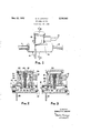
- FIGURE 1 is an overall perspective view of the co-axial switch.
- FIGURE 2 is a cross section taken in the direction of the arrows 2-2 of FIGURE 1 showing the switching components in the oil position;
- FIGURE 3 is a view similar to FIGURE 2 showing the switching components in the on position.
- FIGURE 1 there are shown co-axial line connections 10 and 11 passing into opposite sides of a body member 12.
- 'Ilhe body 12 includes a conducting material which electrically connects the outer conductors of the lines 10 and 11.
- a switch component arranged to be actuated by a suitable mechanism within a housing 13. Remote operation of the switch can be effected by passing a signal into a pair of leads 14 passing to the housing 13 as shown.
- the switch body 12 also includes a mounting bracket 15.
- a flexible conducting reed 18 within the body has one end secured as at 19 to the contact 16. The free end of the reed 18 in turn is arranged to engage a flat contacting surface 20 on the other contact 17 when actuated to connect the inner conductors together.
- the preferred means for actuating the reed 18 from the open position shown in FIGURE 2 to the closed or bridging condition shown in FIGURE 3 comprises a laterally extending plunger 21 terminating at its upper end in a plate 22 including magnetic material and 'provided with a conducting surface engaging the top cover plate 23 of the housing 13 when in the position shown in FIGURE 2.
- the plunger and top end plate 22 are normally held in the position shown by a biasing spring 24. Movement of the plunger is effected by electromagnetic coils 25 surrounding a magnetic core 26 serving as a guide for the plunger itself.
- the plate 22 functions as an armature to complete the magnetic circuit when pulled downwardly.
- the electrical conductors 14 connect to the coils 25 so that the same can be energized to operate the switch from a remote location.
- the flexible reed 18 is biased to the position shown in FIGURE 2 so that its free end engages the outer condue-tor of the co-axial connection 11 as at 27.
- the connection between the inner-conductors is broken and .one of the inner-conductors such as 16 is thetleads 14 to the electro-magnetic coils which pullthe plate 22 downwardly to move the plunger 21 against the reed 18.
- This action will then move the free end of the reed onto the flat contact surface 20 of the contact end of the inner conductor 17 as shown in FIGURE 3.
- a straight through connection is efiected between the inner conductors whereby discontinuities in the geometry of the co-axial lines are minimiZed.
- the preferred embodiment of the switch also includes a stub foreitecting a filtering operation when the switch is in its on position.
- This stub comprises a conductor v28 disposed within the plunger 21 and having its lower end arranged to make electrical contact with the reed 18 as at 29.
- the upper end of the plunger 28 in turn electrically connects to the top plate 22.
- the length of the conducting portion between the point of contact 29 and plate 22 is made equal to one quarter of the mean op erating wave length of the electro-magnetic energy to be passed by the switch.
- the used the flexible reed enables a straight throughconnection to be effected'when the switch is in the on position so that proper impedan'ce'matching and minimum reflections are realized.
- the reed itself is of extremely small mass. This'feature coupled with the fact that thefree 7 noted that the desired filtering action is accomplished by the plunger structure itself so that the one moving component of the actuating structure serves a dual purpose.
- a switch for high frequency electromagnetic energy comprising: a switch body having input and output coaxial connectors in opposite ends, the outer conductors of said connectors being axially aligned and connecting to said body and the inner conductors of said connectors being axially aligned and terminating within saidbody in opposed spaced contacts; a conducting reed disposed between said connectors and adapted upon movement to electrically connect said contacts; an actuating means extending laterally into said body between said connectors, said actuating means including: a plunger; electro-magnetic coils surrounding said plunger, one end of said plunger engaging said conducting reed; and a plate of magnetic material secured to the other end of said plunger for effecting inward movement thereof uponenergization of said coils-to move said reed to connect said contacts and effect a'straight-through co-axial connection, said plunger including a conducting portion in electrical contact with said reed at one end and said plate at its other end, said plate having a conducting surface which engages said body
Description
y 1962 D. H. LANCTOT 3,036,282
CO-AXIAL SWITCH Filed Jan. 18, 1960 FIG. 2 FIG. 3
N VEN TOP DONALD H. LANC'I'OT United States Patent 3,036,282 (IO-AXIAL SWITCH Donald H. Lanctot, Malibu, Calif, assignor to Don-Lan Electronics, Inc, a corporation of California Filed Jan. 18, 1960, Ser. No. 3,149 1 Claim. (Cl. 333--97) This invention relates generally to co-axial switches and more particularly to an improved switch for connection in co-axial lines carrying high frequency electromagnetic energy.
Co-axial switches are well-known in the art and find wide use in high frequency systems. In the design of such switches, it is extremely important that any discontinuities introduced into the co-axial line by the switching components be minimized to avoid possible reflections or loss of power when the switch is in its on position. On the other hand, when the switch is in its off position it is desirable to maximize isolation of the disconnected lines.
In many present day applications, co-axial switches are subject to rugged environmental conditions particularly when employed in missiles. To insure reliability, it is therefore essential that the switching components be capa ble of withstanding shocks, vibrations, high g loading, and the like. In addition, filters are sometimes employed for limiting the frequencies passed to a receiver. The use of such filters minimizes the possibilities of successful jamming of the signal by unauthorized parties. Filters however, constitute additional components in the high frequency system and in cases where weight and space are important, it would be advantageous to combine the desired filtering action with the co-axial switches themselves.
With all of the foregoing in mind, it is a primary object of the present invention to provide an improved coaxial switch for connecting and disconnecting co-axial lines carrying high frequency electro-magnetic energy incorporating the above-noted desirable features.
More particularly, it is an object to provide an improved co-axial switch which employs moving parts of extremely small mass so that the switch can withstand normally encountered shocks, vibrations, and high g loading without loss of reliability.
Another object is to provide a co-axial switch in which a straight through connection for the inner conductors is elfected when the switch is in the on position whereby minimum power loss occurs across the switch.
Still another important object is to provide a switch in which only a given frequency band is passed through the switch when in the on position to the end that the switch itself serves the dual function of both a switch and filter.
Briefly, these and many other objects and advantages of this invention are attained by providing a conducting body receiving input and output co-axial connectors in opposite ends, the outer conductors of the connector being connected through the body and the inner conductors being axially aligned and terminating in opposing contacts within the interior of the body. A flexible conducting reed is secured at one end to one of the inner contacts and biased laterally so that its free end engages the outer conductor of the other of the contacts. In this position, the switch is in its oil condition and the one contact to which the reed is connected is grounded thereby providing excellent isolation. An actuating means extends laterally into the body between the connectors to engage the reed and is arranged to move into the body when actuated to urge the free end of the reed into contact with the other of the inner conductors to effect the desired straight through co-axial connection.
The actuating means itself includes a plunger incorporating a conducting portion having a length corresponding to an odd multiple of a quarter wave length of the mean wave length of the electro-magnetic energy. When the actuating means and switch reed are in the on position, one end of the conducting portion of the plunger engages the reed and the other end spaced at the odd multiple of a quarter wave length engages the body portion of the switch itself so that a. quarter wave stub is provided. Electromagnetic energy of wave lengths different from the quarter wave length defined by the length of the stub will be attenuated whereas electro-magnetic energy of proper wave length defined by the dimensioning of the stub, will pass through the switch, the stub itself appearing as an open circuit.
The plunger may be actuated by electro-magnetic coils so that remote operation of the switch can take place. In this case, the conducting portion of the plunger also serves to complete the magnetic circuit with respect to the coils.
A better understanding of the invention will be had by referring to a preferred embodiment thereof as illustrated in the accompanying drawings in which:
FIGURE 1 is an overall perspective view of the co-axial switch.
FIGURE 2 is a cross section taken in the direction of the arrows 2-2 of FIGURE 1 showing the switching components in the oil position; and,
FIGURE 3 is a view similar to FIGURE 2 showing the switching components in the on position.
Referring first to FIGURE 1, there are shown co-axial line connections 10 and 11 passing into opposite sides of a body member 12. 'Ilhe body 12 includes a conducting material which electrically connects the outer conductors of the lines 10 and 11. Within the interior of the body 12 there is provided a switch component arranged to be actuated by a suitable mechanism within a housing 13. Remote operation of the switch can be effected by passing a signal into a pair of leads 14 passing to the housing 13 as shown. The switch body 12 also includes a mounting bracket 15.
Referring now to FIGURES 2 and 3, it will be noted that the inner conductors of the co-axial lines 10 and 11 terminate in opposed axially spaced contact ends 16 and 17 respectively. A flexible conducting reed 18 within the body has one end secured as at 19 to the contact 16. The free end of the reed 18 in turn is arranged to engage a flat contacting surface 20 on the other contact 17 when actuated to connect the inner conductors together.
The preferred means for actuating the reed 18 from the open position shown in FIGURE 2 to the closed or bridging condition shown in FIGURE 3 comprises a laterally extending plunger 21 terminating at its upper end in a plate 22 including magnetic material and 'provided with a conducting surface engaging the top cover plate 23 of the housing 13 when in the position shown in FIGURE 2. The plunger and top end plate 22 are normally held in the position shown by a biasing spring 24. Movement of the plunger is effected by electromagnetic coils 25 surrounding a magnetic core 26 serving as a guide for the plunger itself. The plate 22 functions as an armature to complete the magnetic circuit when pulled downwardly. As shown in FIGURE 2, the electrical conductors 14 connect to the coils 25 so that the same can be energized to operate the switch from a remote location.
The flexible reed 18 is biased to the position shown in FIGURE 2 so that its free end engages the outer condue-tor of the co-axial connection 11 as at 27. Thus when the switch is in the off position as shown in FIGURE 2, the connection between the inner-conductors is broken and .one of the inner-conductors such as 16 is thetleads 14 to the electro-magnetic coils which pullthe plate 22 downwardly to move the plunger 21 against the reed 18. This action will then move the free end of the reed onto the flat contact surface 20 of the contact end of the inner conductor 17 as shown in FIGURE 3. In this position, it will be noted that a straight through connection is efiected between the inner conductors whereby discontinuities in the geometry of the co-axial lines are minimiZed.-
a When it is desired to open the switch, the signal is removed from the conductors 14- thereby permitting the spring 24 to return the plate 22 and plunger to the position shown in FIGURE 2. The resilient nature of the reed in turn will then move its free end back to the grounded position shown in FIGURE 2.
The preferred embodiment of the switch also includes a stub foreitecting a filtering operation when the switch is in its on position. This stub comprises a conductor v28 disposed within the plunger 21 and having its lower end arranged to make electrical contact with the reed 18 as at 29. The upper end of the plunger 28 in turn electrically connects to the top plate 22. The length of the conducting portion between the point of contact 29 and plate 22 is made equal to one quarter of the mean op erating wave length of the electro-magnetic energy to be passed by the switch. a When the switch is in'thefoft position as shown in FIGURE '2, the conductor 28 within everal advantages accrue from the foregoing described construction. As-already' mentioned, the used the flexible reed enables a straight throughconnection to be effected'when the switch is in the on position so that proper impedan'ce'matching and minimum reflections are realized. In addition, the reed itself is of extremely small mass. This'feature coupled with the fact that thefree 7 noted that the desired filtering action is accomplished by the plunger structure itself so that the one moving component of the actuating structure serves a dual purpose.
Modifications that fall clearly within the scope and spirit of this invention will occur to those skilled in the art. The co-axial switch is therefore not to be thought of as limited to the particular embodiment set forth merely for illustrative purposes.
What is claimed is:
A switch for high frequency electromagnetic energy, comprising: a switch body having input and output coaxial connectors in opposite ends, the outer conductors of said connectors being axially aligned and connecting to said body and the inner conductors of said connectors being axially aligned and terminating within saidbody in opposed spaced contacts; a conducting reed disposed between said connectors and adapted upon movement to electrically connect said contacts; an actuating means extending laterally into said body between said connectors, said actuating means including: a plunger; electro-magnetic coils surrounding said plunger, one end of said plunger engaging said conducting reed; and a plate of magnetic material secured to the other end of said plunger for effecting inward movement thereof uponenergization of said coils-to move said reed to connect said contacts and effect a'straight-through co-axial connection, said plunger including a conducting portion in electrical contact with said reed at one end and said plate at its other end, said plate having a conducting surface which engages said body when said coils are energized and said plate is moved, said conducting portion of said plunger having a length equal to an odd multiple of the quarter wave length of the mean wave length'of said electro-rnagnetic energy, whereby said plunger electrically connects said reed to said body when said straight-through co-axial' connection-is effected to provide a quarter wave length filtering stub.
References Cited in the file of this patent
Priority Applications (1)
| Application Number | Priority Date | Filing Date | Title |
|---|---|---|---|
| US3149A US3036282A (en) | 1960-01-18 | 1960-01-18 | Co-axial switch |
Applications Claiming Priority (1)
| Application Number | Priority Date | Filing Date | Title |
|---|---|---|---|
| US3149A US3036282A (en) | 1960-01-18 | 1960-01-18 | Co-axial switch |
Publications (1)
| Publication Number | Publication Date |
|---|---|
| US3036282A true US3036282A (en) | 1962-05-22 |
Family
ID=21704415
Family Applications (1)
| Application Number | Title | Priority Date | Filing Date |
|---|---|---|---|
| US3149A Expired - Lifetime US3036282A (en) | 1960-01-18 | 1960-01-18 | Co-axial switch |
Country Status (1)
| Country | Link |
|---|---|
| US (1) | US3036282A (en) |
Cited By (7)
| Publication number | Priority date | Publication date | Assignee | Title |
|---|---|---|---|---|
| US4074099A (en) * | 1976-12-27 | 1978-02-14 | The United States Of America As Represented By The Secretary Of The Navy | Coaxial, polarity-reversing switch |
| US4652840A (en) * | 1984-07-20 | 1987-03-24 | Nec Corporation | Ultrahigh-frequency switch |
| WO1987007437A1 (en) * | 1986-05-28 | 1987-12-03 | F L Jennings Division Of F L Industries, Inc. | High frequency electrical switch |
| US4782313A (en) * | 1988-01-12 | 1988-11-01 | General Electric Company | Transmission line shorting switch |
| EP0361638A2 (en) * | 1988-09-28 | 1990-04-04 | Com Dev Ltd. | Microwave C-switches and S-switches |
| US5207318A (en) * | 1991-07-29 | 1993-05-04 | Dynatech Microwave Technology, Inc. | Plunger switch |
| US5491315A (en) * | 1993-09-07 | 1996-02-13 | Raychem Corporation | Switching device with slidable switch |
Citations (7)
| Publication number | Priority date | Publication date | Assignee | Title |
|---|---|---|---|---|
| US2510299A (en) * | 1945-01-01 | 1950-06-06 | Bell Telephone Labor Inc | Pulse-echo testing system |
| US2662142A (en) * | 1950-11-03 | 1953-12-08 | Nelson Jessie Ann | Coaxial-line switch |
| FR1174469A (en) * | 1957-05-03 | 1959-03-11 | Radiall Sa | Coaxial relay or switch for coaxial lines controlled by relay |
| US2911498A (en) * | 1958-01-17 | 1959-11-03 | Cons Electronics Ind | Coaxial relay |
| US2926318A (en) * | 1956-06-26 | 1960-02-23 | Electronic Specialty Co | Miniature co-axial switch |
| US2938176A (en) * | 1958-03-31 | 1960-05-24 | Ryan Aeronautical Co | Electronic antenna scanning switch |
| US2941164A (en) * | 1957-01-18 | 1960-06-14 | Electronic Specialty Co | Manual co-axial switch |
-
1960
- 1960-01-18 US US3149A patent/US3036282A/en not_active Expired - Lifetime
Patent Citations (7)
| Publication number | Priority date | Publication date | Assignee | Title |
|---|---|---|---|---|
| US2510299A (en) * | 1945-01-01 | 1950-06-06 | Bell Telephone Labor Inc | Pulse-echo testing system |
| US2662142A (en) * | 1950-11-03 | 1953-12-08 | Nelson Jessie Ann | Coaxial-line switch |
| US2926318A (en) * | 1956-06-26 | 1960-02-23 | Electronic Specialty Co | Miniature co-axial switch |
| US2941164A (en) * | 1957-01-18 | 1960-06-14 | Electronic Specialty Co | Manual co-axial switch |
| FR1174469A (en) * | 1957-05-03 | 1959-03-11 | Radiall Sa | Coaxial relay or switch for coaxial lines controlled by relay |
| US2911498A (en) * | 1958-01-17 | 1959-11-03 | Cons Electronics Ind | Coaxial relay |
| US2938176A (en) * | 1958-03-31 | 1960-05-24 | Ryan Aeronautical Co | Electronic antenna scanning switch |
Cited By (9)
| Publication number | Priority date | Publication date | Assignee | Title |
|---|---|---|---|---|
| US4074099A (en) * | 1976-12-27 | 1978-02-14 | The United States Of America As Represented By The Secretary Of The Navy | Coaxial, polarity-reversing switch |
| US4652840A (en) * | 1984-07-20 | 1987-03-24 | Nec Corporation | Ultrahigh-frequency switch |
| WO1987007437A1 (en) * | 1986-05-28 | 1987-12-03 | F L Jennings Division Of F L Industries, Inc. | High frequency electrical switch |
| US4749967A (en) * | 1986-05-28 | 1988-06-07 | F L Jennings Division Of F L Industries, Inc. | High frequency electrical switch |
| US4782313A (en) * | 1988-01-12 | 1988-11-01 | General Electric Company | Transmission line shorting switch |
| EP0361638A2 (en) * | 1988-09-28 | 1990-04-04 | Com Dev Ltd. | Microwave C-switches and S-switches |
| EP0361638A3 (en) * | 1988-09-28 | 1991-10-02 | Com Dev Ltd. | Microwave c-switches and s-switches |
| US5207318A (en) * | 1991-07-29 | 1993-05-04 | Dynatech Microwave Technology, Inc. | Plunger switch |
| US5491315A (en) * | 1993-09-07 | 1996-02-13 | Raychem Corporation | Switching device with slidable switch |
Similar Documents
| Publication | Publication Date | Title |
|---|---|---|
| US3873785A (en) | Electrical connector | |
| US5702262A (en) | Connector assembly | |
| US4862182A (en) | Antenna for a portable radiotelephone | |
| US2498907A (en) | Radio frequency shielded switch | |
| US3036282A (en) | Co-axial switch | |
| US3019402A (en) | Step attenuator | |
| US3739306A (en) | Microwave coaxial switch | |
| EP0869584A1 (en) | Coaxial connector for switching antennas | |
| US3319194A (en) | Variable attenuator employing internal switching | |
| US3374449A (en) | Coaxial switch | |
| US2388049A (en) | Attenuator | |
| US3289112A (en) | Strip transmission line ferrite filterlimiter having a ferrite sphere positioned beneath overlapping conductors | |
| US3088081A (en) | Coaxial switch having improved crosstalk characteristics | |
| US3414849A (en) | Radio frequency coaxial switches | |
| US3831114A (en) | Encapsulated microstrip circulator with mode elimination means | |
| US3184693A (en) | Liquid displacement electric circuit forming device | |
| US2640115A (en) | Electrical switch | |
| US2642495A (en) | Coaxial transmission line switch | |
| US3141943A (en) | Co-axial switch | |
| US3993970A (en) | Coaxial cable switch | |
| US3614683A (en) | Multiple-contact glass-sealed dry reed switching device | |
| US3087129A (en) | Centerless coaxial connector | |
| US6429758B1 (en) | Miniature electromechanical switch | |
| US3114887A (en) | High frequency coaxial switch employing strip-line techniques | |
| US2842637A (en) | Microstrip switch |