US2995016A - Separation or partial separation of components of a liquid medium - Google Patents
Separation or partial separation of components of a liquid medium Download PDFInfo
- Publication number
- US2995016A US2995016A US790651A US79065159A US2995016A US 2995016 A US2995016 A US 2995016A US 790651 A US790651 A US 790651A US 79065159 A US79065159 A US 79065159A US 2995016 A US2995016 A US 2995016A
- Authority
- US
- United States
- Prior art keywords
- cylinder
- separation
- solid
- components
- liquid
- Prior art date
- Legal status (The legal status is an assumption and is not a legal conclusion. Google has not performed a legal analysis and makes no representation as to the accuracy of the status listed.)
- Expired - Lifetime
Links
Images


Classifications
-
- C—CHEMISTRY; METALLURGY
- C02—TREATMENT OF WATER, WASTE WATER, SEWAGE, OR SLUDGE
- C02F—TREATMENT OF WATER, WASTE WATER, SEWAGE, OR SLUDGE
- C02F1/00—Treatment of water, waste water, or sewage
- C02F1/22—Treatment of water, waste water, or sewage by freezing
-
- A—HUMAN NECESSITIES
- A23—FOODS OR FOODSTUFFS; TREATMENT THEREOF, NOT COVERED BY OTHER CLASSES
- A23L—FOODS, FOODSTUFFS, OR NON-ALCOHOLIC BEVERAGES, NOT COVERED BY SUBCLASSES A21D OR A23B-A23J; THEIR PREPARATION OR TREATMENT, e.g. COOKING, MODIFICATION OF NUTRITIVE QUALITIES, PHYSICAL TREATMENT; PRESERVATION OF FOODS OR FOODSTUFFS, IN GENERAL
- A23L2/00—Non-alcoholic beverages; Dry compositions or concentrates therefor; Their preparation
- A23L2/02—Non-alcoholic beverages; Dry compositions or concentrates therefor; Their preparation containing fruit or vegetable juices
- A23L2/08—Concentrating or drying of juices
- A23L2/12—Concentrating or drying of juices by freezing
-
- B—PERFORMING OPERATIONS; TRANSPORTING
- B01—PHYSICAL OR CHEMICAL PROCESSES OR APPARATUS IN GENERAL
- B01D—SEPARATION
- B01D9/00—Crystallisation
- B01D9/0004—Crystallisation cooling by heat exchange
- B01D9/0013—Crystallisation cooling by heat exchange by indirect heat exchange
-
- B—PERFORMING OPERATIONS; TRANSPORTING
- B01—PHYSICAL OR CHEMICAL PROCESSES OR APPARATUS IN GENERAL
- B01D—SEPARATION
- B01D9/00—Crystallisation
- B01D9/004—Fractional crystallisation; Fractionating or rectifying columns
Definitions
- This invention relates to the separation or partial separation of components of a liquid medium.
- a process for the separation or partial separation of components of a liquid medium comprises feeding the liquid mixture into a movable duct, cooling a portion of the liquid to form a solid phase carried by the duct, moving the duct to raise the solid phase relative to the liquid phase, warming a suitable portion of the solid to cause the solid to liquefy and the melt to descend by gravity to a cooler region where it again partially solidifies whilst the mother liquors have passed along the duct, so that the separated or partially separated components are moved towards opposite ends of the duct, and withdrawing the separated fractions.
- the process of the invention is applicable to liquid mixtures of all types, including suspensions and emulsions.
- the process can be used to separate mixtures of cresols, to purify salt water or to concentrate fruit juices.
- FIGURE 1 is a section of one form of apparatus
- FIGURE 2 is a section along the line II-II in FIG. 1;
- FIGURE 3 is a detail of an apparatus similar to that shown in FIG. 1;
- FIGURE 4 is a section of a modification of the apparatus shown in FIG. 1;
- FIGURE 5 is a section along the line V-V in FIG. 4;
- FIGURE 6 is a detail of part of a modification of the apparatus of FIGS. 4 and 5;
- FIGURE 7 is a section of another form of apparatus
- FIGURE 8 is a section along the line VIII-VIII in FIG. 7;
- FIGURE 9 is a section of a modified form of the apparatus shown in FIGS. 7 and 8;
- FIGURE 10 is a sectional plan of a further form of apparatus
- FIGURE 11 is a sectional elevation of the apparatus shown in FIG. 10.
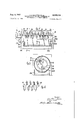
- FIGURES l and 2 consists of a horizontally disposed hollow cylinder 1 which has a helical thread 2 on its inner surface.
- the cylinder is closed by annular insulated end plates 3 each of which has a flange extending along the cylinder to insulate the end compartment.
- the cylinder is rotated by engagement of a collar'4 on the inner. edge of the end plates 3 with friction drive wheels 5 carried by a shaft 6 driven at one end by a motor 7.
- the shaft 6 is mounted at its other end on a support member 8 and the motor 7 is mounted on a plate 9 carried by a second support member 10. Axial movement of the cylinder 1 is prevented by flanges 11 on the drive wheels 5.
- the liquid mixture to be separated is introduced into the centre of the cylinder 1 through the space in the end Patented Aug. 8, 1961 wall 3 by a feed pipe 12.
- the level of the liquid 13 in the cylinder 1 is controlled by a constant level device which comprises a float 14 which operates the valve 15 in the feed pipe 12.
- the separated fractions are removed from opposite ends of the cylinder 1 through outlet tubes 16 and by pumps 17 and 170.
- the lower part of the cylinder 1 dips into a refrigerating bath 18 so that solid material 19 is formed and adheres to the wall of the cylinder 1.
- the level of the refrigerant 20 in the refrigerating bath 18 is preferably above the level of the liquid 13 in the cylinder 1, as shown in FIGS. 1 and 2.
- the solid material 19 adhering to the walls of the cylinder is carried as the cylinder 1 rotates past a heating element 21 which is positioned past top dead centre in the direction of rotation and which extends along the length of the cylinder 1 completely.
- the solid 19 is completely melted there and runs forward under gravity following the thread 2 into the cooled portion of the cylinder.
- the solid material just to the left of one of the blades 2 moves through more than and is then melted, it will flow down the wall under the influence of gravity on the right hand side of the spiral whereas, in the meanwhile, the still liquid phase has been transferred one step to the right, so that the melted substance will mix with the liquid in the preceding section.
- the gravitational forces thus cause a liquid phase enriched in higher melting fraction to move along the thread (to the right, FIG. 1) whereas the correspondingly depleted liquid phase is moved in the opposite direction (to the left, FIG. 1) by rotation of the thread.
- the cylinder 1 may be driven intermittently or continuously.
- the speed of rotation and the method of driving it clearly depend to some extent on the freezing characteristics of the particular liquid mixture being separated.
- The, heating element 21 may be heated electrically or with steam which-ever is convenient. In some cases it may be dispensed with as the solid formed will melt at room temperature. Similarly the cooling bath 18 may be unnecessary in certain cases.
- FIG. 3 shows a cylinder 1a for use in the apparatus of FIG. 1 which has of melting the solids can be used however, for example, in i the apparatus shown in FIGS. 4 and 5 a spiral 24 consisting of a set of blades arranged helically on the-shaft 23 is used.
- the radius of the spiral 24 is less than the radius of the cylinder 1b and it is positioned so that it intermeshes with the thread 212 on the cylinder 1b at a point past top dead centre.
- the pitch of the spiral 24 is half that of the thread 2b and it is rotated by the motor 7b through the gears in the box 25 at an angular velocity twice that of the cylinder 1b to prevent the spiral 24 from moving out of the cylinder 1b. Because of the difference in radii and in the number of turns of the two spirals the peripheral speed of the cyl inder 1b will in general diifer from that of the spiral 24 and so that the wall f the cylinder 1b will scrape over the blades of the spiral 24. The solid is thus brought into contact with the heated spiral 24 for sufficiently long time to melt it.
- the blades of the spiral 24 have the shape shown in FIG. 6, as this is more efiicient.
- the forni shown in FIGS. 4 and 5 is shown for clarity of the drawings.
- the liquid mixture is fed into an internally threaded cylinder 10 containing a hollow coil 26 through which refrigerant passes. Both the coil 26 and the cylinder 10 are rotated by shafts feeding means and means. for withdrawing the separated components are similar to those shown in FIGS. 1 and 2.
- the embodiment shown in H6. 9 is generally similar to that shown in FIGS. 7 and 8'.
- the efiiciency of the apparatus is increased by increasing the number ofturns of the refrigeratedcoil 26d with consequential increase in the speed of its rotationrelative to the speed of the outer cylinder 10'.
- the cylinder 1d and the coil 26d anchored to the support member 8d by a spring 31. The.
- scraper 28d is suitably shaped so that melted solid will collect in it and flow forward to the compartment in the outer cylinder 1d next to the compartment in which the solid was formed.
- a scraper 28d, V or U shaped in cross-section which is deeper at one end than the other and having holes spaced at intervals corresponding to the pitch of the outer spiral 1d is suitable.
- the rack and pinion mechanism causes the scraper 28d to move across three turns of the refrigerated coil 26d during one revolution of the outer cylinder 10? against the action of the spring 31. At the end of each revolution of the outer cylinder 1d the scraper 28d is reciprocated by the spring 31. This mechanism ensures that the solid formed on the coil in one compartment of the cylinder is movedforward into the next compartment on melting.
- the refrigerated coil 2&3 or. 28d may be such that the flat outer surface only is refrigerated and the width of the flat portions of the coil 280 may be about-equal to the pitch of the outer spirally.
- FIG. 10 Another further form of apparatus is shown in FIG. 10. It comprises a trough 50 which, is divided by; triangular partitions 51 into a zig-zag track 52.
- the apparatus is tilted in different directions by rods 53a, b, c, and d which are reciprocated by hydraulic or other actuators 61a, b, c, and d so as to bring different parts of the channel 52 in to tilt the trough both longi tudinally and transversely so as to heated zones, or cooled zones, and also to allow liquid portions of material tofiow in any desired direction along the zig-zag, path 52;
- the means of operation is closely related to that; of the rotating cylinder. Essentially some solid is frozen by dipping one edge of the trough 50 into a coolingbath 54 (rods 53a and b short, andd long), the trough50,
- the next stage consists in bringing the other edge of; the. trough Shinto the refrigerating bat-h 54- (rodsz53'aand b 4 sidered above thereby completing the cycle.
- the sequence is repeated in a continuous manner.
- the separated fractions are withdrawn through pipes 59 and 60 at each end of the track 52 and the liquid mixture is fed into the track 52 near the centre of the trough 50;
- a certain amountof conservation of latent heat, as in adistillation column, can be achievedin the operation long, 0 and d shortland then suitably tilting the trough so that the mother liquors and melted solid flow. alongthe track in the same opposed. directions as before.
- heater 56 is used to melt the solid formed at thisstage.
- the trough SO- is restored to the original position conof all modifications if a temperature gradient is arranged in such a manner that partial melting of the solid phase occursduring its upward progress. This results in some reflux and liquid-solid equilibration and hence increased efficiency of separation without (in principle) additional heat input;
- a process for the separation or partial separation of components of a liquid medium which comprises feeding the liquid mixture into a movable and regularly winding duct, cooling a surface in contact with the'liquid to form an adhering solid phase, moving the duct to alter the relative levels of portions of the duct, simultaneously raising the solid phase relative to the liquid phase, warmi-ng a suitable portion of the solid to cause the solid phase to liquefy and the melt to flow by gravity to a cooler region of the duct where it again partially solidifies at positions along the duct diifering from those in which the solid phase was first formed, movement of the duct causing the mother liquors to pass along the duct so-that the separated or partially separated components are moved towards opposite ends of the duct withoutbeing brought into contact with freshly introduced liquid mixture and withdrawing the separated fractions.
Description
Aug. 8, 19 1 x. R. BEATTlE ET AL 2,995,016
SEPARATION OR PARTIAL SEPARATION OF COMPONENTS OF A LIQUID MEDIUM Filed Feb. 2, 1959 5 Sheets-Sheet 1 In ventors M M 9/ Attorfey;
1951 l. R. BEATTIE ET AL 2,995,016
SEPARATION OR PARTIAL SEPARATION OF COMPONENTS OF A LIQUID MEDIUM Filed Feb. 2, 1959 5 Sheets-Sheet 2 F 25 86 l/eb 23 2/701) Inventors I. R. BEATTIE ET AL SEPARATION OR PARTIAL SEPARATION OF COMPONENTS OF A IIQUID MEDIUM Aug. 8, 1961 5 Sheets-Sheet 3 Filed Feb. 2, 1959 In veniors Jaw fdzzzz 2221/7/25 V [ac 6 a A/ A ttorney:
Aug. 8, 1961 1. R. BEATTIE ET AL 2,995,016
SEPARATION OR PARTIAL SEPARATION OF COMPONENTS OF A LIQUID MEDIUM Filed Feb. 2, 1959 s Sheets-Sheet 4 In venton Aug. 8, 1961 I. R. BEATTIE ET AL 2,995,016
SEPARATION OR PARTIAL SEPARATION OF COMPONENTS OF A LIQUID MEDIUM Filed. Feb. 2, 1959 s Sheets-$heet 5 54 liq/Q 5 5/ lnventon United States Patent 2,995,016 SEPARATION 0R PA RTIAL SEPARATION OF COMPONENTS OF A LIQUID MEDIUM Ian Robert Beattie, 19B Cliff Parade, Leigh-on-Sea, England, and Victor Gold, 7 Manor Gardens, South Croydon, England Filed Feb. 2, 1959, Ser. No. 790,651 Claims priority, application Great Britain Feb. 6, 195
6 Claims. (Cl. 62-58) This invention relates to the separation or partial separation of components of a liquid medium.
It is well known that liquid mixtures may be separated by fractional crystallisation. However, heretofore such methods have been generally cumbersome, time consuming or inefiicient. This invention is particularly directed to a convenient process whereby multiple or fractional crystallisations may be carried out continuously, on either a large or a small scale.
According to the invention, a process for the separation or partial separation of components of a liquid medium comprises feeding the liquid mixture into a movable duct, cooling a portion of the liquid to form a solid phase carried by the duct, moving the duct to raise the solid phase relative to the liquid phase, warming a suitable portion of the solid to cause the solid to liquefy and the melt to descend by gravity to a cooler region where it again partially solidifies whilst the mother liquors have passed along the duct, so that the separated or partially separated components are moved towards opposite ends of the duct, and withdrawing the separated fractions.
The process of the invention is applicable to liquid mixtures of all types, including suspensions and emulsions. For example the process can be used to separate mixtures of cresols, to purify salt water or to concentrate fruit juices.
Various forms of apparatus can be used to carry out the process of the invention. Some examples of these are shown in the accompanying drawings in which:
FIGURE 1 is a section of one form of apparatus;
FIGURE 2 is a section along the line II-II in FIG. 1;
FIGURE 3 is a detail of an apparatus similar to that shown in FIG. 1;
FIGURE 4 is a section of a modification of the apparatus shown in FIG. 1;
FIGURE 5 is a section along the line V-V in FIG. 4;
FIGURE 6 is a detail of part of a modification of the apparatus of FIGS. 4 and 5;
FIGURE 7 is a section of another form of apparatus;
FIGURE 8 is a section along the line VIII-VIII in FIG. 7;
FIGURE 9 is a section of a modified form of the apparatus shown in FIGS. 7 and 8;
FIGURE 10 is a sectional plan of a further form of apparatus;
FIGURE 11 is a sectional elevation of the apparatus shown in FIG. 10.
The form of apparatus shown in FIGURES l and 2 consists of a horizontally disposed hollow cylinder 1 which has a helical thread 2 on its inner surface. The cylinder is closed by annular insulated end plates 3 each of which has a flange extending along the cylinder to insulate the end compartment. The cylinder is rotated by engagement of a collar'4 on the inner. edge of the end plates 3 with friction drive wheels 5 carried by a shaft 6 driven at one end by a motor 7. The shaft 6 is mounted at its other end on a support member 8 and the motor 7 is mounted on a plate 9 carried by a second support member 10. Axial movement of the cylinder 1 is prevented by flanges 11 on the drive wheels 5.
The liquid mixture to be separated is introduced into the centre of the cylinder 1 through the space in the end Patented Aug. 8, 1961 wall 3 by a feed pipe 12. The level of the liquid 13 in the cylinder 1 is controlled by a constant level device which comprises a float 14 which operates the valve 15 in the feed pipe 12. The separated fractions are removed from opposite ends of the cylinder 1 through outlet tubes 16 and by pumps 17 and 170. The lower part of the cylinder 1 dips into a refrigerating bath 18 so that solid material 19 is formed and adheres to the wall of the cylinder 1. The level of the refrigerant 20 in the refrigerating bath 18 is preferably above the level of the liquid 13 in the cylinder 1, as shown in FIGS. 1 and 2.
The solid material 19 adhering to the walls of the cylinder is carried as the cylinder 1 rotates past a heating element 21 which is positioned past top dead centre in the direction of rotation and which extends along the length of the cylinder 1 completely. The solid 19 is completely melted there and runs forward under gravity following the thread 2 into the cooled portion of the cylinder. For example, when the solid material just to the left of one of the blades 2 moves through more than and is then melted, it will flow down the wall under the influence of gravity on the right hand side of the spiral whereas, in the meanwhile, the still liquid phase has been transferred one step to the right, so that the melted substance will mix with the liquid in the preceding section. The gravitational forces thus cause a liquid phase enriched in higher melting fraction to move along the thread (to the right, FIG. 1) whereas the correspondingly depleted liquid phase is moved in the opposite direction (to the left, FIG. 1) by rotation of the thread.
The cylinder 1 may be driven intermittently or continuously. The speed of rotation and the method of driving it clearly depend to some extent on the freezing characteristics of the particular liquid mixture being separated.
The, heating element 21 may be heated electrically or with steam which-ever is convenient. In some cases it may be dispensed with as the solid formed will melt at room temperature. Similarly the cooling bath 18 may be unnecessary in certain cases.
Various modifications of the apparatus shown in FIGS. 1 and 2 may be made. Multistart threads may be used instead of a single start thread. Thus FIG. 3 shows a cylinder 1a for use in the apparatus of FIG. 1 which has of melting the solids can be used however, for example, in i the apparatus shown in FIGS. 4 and 5 a spiral 24 consisting of a set of blades arranged helically on the-shaft 23 is used. The radius of the spiral 24 is less than the radius of the cylinder 1b and it is positioned so that it intermeshes with the thread 212 on the cylinder 1b at a point past top dead centre. In the apparatus shown the pitch of the spiral 24 is half that of the thread 2b and it is rotated by the motor 7b through the gears in the box 25 at an angular velocity twice that of the cylinder 1b to prevent the spiral 24 from moving out of the cylinder 1b. Because of the difference in radii and in the number of turns of the two spirals the peripheral speed of the cyl inder 1b will in general diifer from that of the spiral 24 and so that the wall f the cylinder 1b will scrape over the blades of the spiral 24. The solid is thus brought into contact with the heated spiral 24 for sufficiently long time to melt it.
:Preferably the blades of the spiral 24 have the shape shown in FIG. 6, as this is more efiicient. The forni shown in FIGS. 4 and 5 is shown for clarity of the drawings.
In the apparatus shown in FIGS. 7 and 8, the liquid mixture is fed into an internally threaded cylinder 10 containing a hollow coil 26 through which refrigerant passes. Both the coil 26 and the cylinder 10 are rotated by shafts feeding means and means. for withdrawing the separated components are similar to those shown in FIGS. 1 and 2. The embodiment shown in H6. 9 is generally similar to that shown in FIGS. 7 and 8'. However, the efiiciency of the apparatus is increased by increasing the number ofturns of the refrigeratedcoil 26d with consequential increase in the speed of its rotationrelative to the speed of the outer cylinder 10'. The cylinder 1d and the coil 26d anchored to the support member 8d by a spring 31. The.
scraper 28d is suitably shaped so that melted solid will collect in it and flow forward to the compartment in the outer cylinder 1d next to the compartment in which the solid was formed. A scraper 28d, V or U shaped in cross-section which is deeper at one end than the other and having holes spaced at intervals corresponding to the pitch of the outer spiral 1d is suitable. The rack and pinion mechanism causes the scraper 28d to move across three turns of the refrigerated coil 26d during one revolution of the outer cylinder 10? against the action of the spring 31. At the end of each revolution of the outer cylinder 1d the scraper 28d is reciprocated by the spring 31. This mechanism ensures that the solid formed on the coil in one compartment of the cylinder is movedforward into the next compartment on melting.
The refrigerated coil 2&3 or. 28d may be such that the flat outer surface only is refrigerated and the width of the flat portions of the coil 280 may be about-equal to the pitch of the outer spirally.
Another further form of apparatus is shown in FIG. 10. It comprises a trough 50 which, is divided by; triangular partitions 51 into a zig-zag track 52.
The apparatus is tilted in different directions by rods 53a, b, c, and d which are reciprocated by hydraulic or other actuators 61a, b, c, and d so as to bring different parts of the channel 52 in to tilt the trough both longi tudinally and transversely so as to heated zones, or cooled zones, and also to allow liquid portions of material tofiow in any desired direction along the zig-zag, path 52;
The means of operation is closely related to that; of the rotating cylinder. Essentially some solid is frozen by dipping one edge of the trough 50 into a coolingbath 54 (rods 53a and b short, andd long), the trough50,
is then tilted diagonally, downwardly towards the upper left, FIG. 10, sothat the mother liquors fiow awayrfrom the solid in the required direction (rod 530 short along b and a! intermediate), the trough 5.0 is'tipped in another direction (diagonally downwardly towards the upper right, FIG. and the frozen material warmedv by a heater. 55;
so that it melts and runs down inthe opposite direction,
along the zigzag path 52 to that taken by the mother liquors (rods 53d short b long a and 0 intermediate). The next stage consists in bringing the other edge of; the. trough Shinto the refrigerating bat-h 54- (rodsz53'aand b 4 sidered above thereby completing the cycle. The sequence is repeated in a continuous manner.
The separated fractions are withdrawn through pipes 59 and 60 at each end of the track 52 and the liquid mixture is fed into the track 52 near the centre of the trough 50;
A certain amountof conservation of latent heat, as in adistillation column, can be achievedin the operation long, 0 and d shortland then suitably tilting the trough so that the mother liquors and melted solid flow. alongthe track in the same opposed. directions as before. The
We claim:
1. A process for the separation or partial separation of components of a liquid medium, which comprises feeding the liquid mixture into a movable and regularly winding duct, cooling a surface in contact with the'liquid to form an adhering solid phase, moving the duct to alter the relative levels of portions of the duct, simultaneously raising the solid phase relative to the liquid phase, warmi-ng a suitable portion of the solid to cause the solid phase to liquefy and the melt to flow by gravity to a cooler region of the duct where it again partially solidifies at positions along the duct diifering from those in which the solid phase was first formed, movement of the duct causing the mother liquors to pass along the duct so-that the separated or partially separated components are moved towards opposite ends of the duct withoutbeing brought into contact with freshly introduced liquid mixture and withdrawing the separated fractions.
2. A-processas claimed in claim 1, in which the solid passesthrough a temperature gradient so that refluxing occurs as thesolid is raised.
3. A'process as claimed in claim 1, in which the liquid mixture is fed into a cylinder having an internalthreacl,
such that it contacts the cylinder walls at. a point past,
top dead center.
5. A process as claimed in claim 3, inwhich thesolid phase .forms onthe surface of a refrigerated, coil inside the internally. threaded cylinder rotated at a ratecorrelated to that of the cylinder and solid is removedfromthe refrigeratedcoil byv a heatedscraper.
6. A, process as claimed inclaim 1, in which the liquid mixture is fed into a zig-zag track, which is tilted, such that. solidlis formed when: either edge of the; track is. at its lowest position, and melted at; its highest. position, the; track being alternately tilted} diagonally in opposite directions so that the mother liquors and meltedsolid are caused to flow in opposite; directions along the zigzag track.
, References Cited in the file of this patent UNITED STATES PATENTS 1,868,406 Bonath July 19, 1932 1,931,347 Gay Oct. :17, 1933 1,999,712 Zorn Apr. 30, 1935 2,552,524 Cunningham May 15, 1951. 2,603,667 Pankratz July 15, 1952 2,617;273 Findlay Nov. 11, 1952 2,942,429 Van Dolahet a1; June 28, 1960
Applications Claiming Priority (1)
| Application Number | Priority Date | Filing Date | Title |
|---|---|---|---|
| GB2995016X | 1958-02-06 |
Publications (1)
| Publication Number | Publication Date |
|---|---|
| US2995016A true US2995016A (en) | 1961-08-08 |
Family
ID=10919388
Family Applications (1)
| Application Number | Title | Priority Date | Filing Date |
|---|---|---|---|
| US790651A Expired - Lifetime US2995016A (en) | 1958-02-06 | 1959-02-02 | Separation or partial separation of components of a liquid medium |
Country Status (2)
| Country | Link |
|---|---|
| US (1) | US2995016A (en) |
| FR (1) | FR1220220A (en) |
Cited By (6)
| Publication number | Priority date | Publication date | Assignee | Title |
|---|---|---|---|---|
| US3254500A (en) * | 1962-10-23 | 1966-06-07 | Independence Foundation | Freeze-refining apparatus |
| US3338064A (en) * | 1961-11-24 | 1967-08-29 | Blaw Knox Co | Ice melting system |
| US3543531A (en) * | 1967-05-08 | 1970-12-01 | Clyde C Adams | Freeze refining apparatus |
| US5186019A (en) * | 1990-05-31 | 1993-02-16 | Messer Griesheim Gmbh | Device to freeze free-flowing and pourable substances |
| US20140166238A1 (en) * | 2011-08-11 | 2014-06-19 | Nestec S.A. | Liquid-cryogen injection cooling devices and methods for using same |
| WO2017016659A1 (en) * | 2015-07-29 | 2017-02-02 | Heitmann Torsten | Crystallizer or reactor and method for continuously growing crystals or continuously managing a reaction |
Families Citing this family (3)
| Publication number | Priority date | Publication date | Assignee | Title |
|---|---|---|---|---|
| US4809519A (en) * | 1988-04-18 | 1989-03-07 | Cheng Chen Yen | Methods and apparatuses for conducting solid-liquid-vapor multiple phase transformation operations |
| AU642054B2 (en) * | 1990-11-27 | 1993-10-07 | Gebruder Sulzer Aktiengesellschaft | Device for substance separation from a liquid mixture by crystallization |
| DE4041670C1 (en) * | 1990-12-22 | 1992-07-30 | Santrade Ltd., Luzern, Ch |
Citations (7)
| Publication number | Priority date | Publication date | Assignee | Title |
|---|---|---|---|---|
| US1868406A (en) * | 1928-10-11 | 1932-07-19 | Werkspoor Nv | Apparatus for the heat treatment of sugar solutions either completely or partly crystallized |
| US1931347A (en) * | 1932-01-13 | 1933-10-17 | Norman H Gay | Apparatus for preparing potable water |
| US1999712A (en) * | 1931-06-30 | 1935-04-30 | Low Temperature Proc Company | Method of treatment and concentration of liquids by freezing |
| US2552524A (en) * | 1948-07-01 | 1951-05-15 | Commonweatlth Engineering Comp | Apparatus for extracting liquid to form a concentrate |
| US2603667A (en) * | 1950-01-26 | 1952-07-15 | Phillips Petroleum Co | Fractional crystallization |
| US2617273A (en) * | 1949-04-25 | 1952-11-11 | Phillips Petroleum Co | Continuous crystallization apparatus and process |
| US2942429A (en) * | 1957-04-29 | 1960-06-28 | Swift & Co | Poultry chilling |
-
1959
- 1959-02-02 US US790651A patent/US2995016A/en not_active Expired - Lifetime
- 1959-02-06 FR FR786031A patent/FR1220220A/en not_active Expired
Patent Citations (7)
| Publication number | Priority date | Publication date | Assignee | Title |
|---|---|---|---|---|
| US1868406A (en) * | 1928-10-11 | 1932-07-19 | Werkspoor Nv | Apparatus for the heat treatment of sugar solutions either completely or partly crystallized |
| US1999712A (en) * | 1931-06-30 | 1935-04-30 | Low Temperature Proc Company | Method of treatment and concentration of liquids by freezing |
| US1931347A (en) * | 1932-01-13 | 1933-10-17 | Norman H Gay | Apparatus for preparing potable water |
| US2552524A (en) * | 1948-07-01 | 1951-05-15 | Commonweatlth Engineering Comp | Apparatus for extracting liquid to form a concentrate |
| US2617273A (en) * | 1949-04-25 | 1952-11-11 | Phillips Petroleum Co | Continuous crystallization apparatus and process |
| US2603667A (en) * | 1950-01-26 | 1952-07-15 | Phillips Petroleum Co | Fractional crystallization |
| US2942429A (en) * | 1957-04-29 | 1960-06-28 | Swift & Co | Poultry chilling |
Cited By (9)
| Publication number | Priority date | Publication date | Assignee | Title |
|---|---|---|---|---|
| US3338064A (en) * | 1961-11-24 | 1967-08-29 | Blaw Knox Co | Ice melting system |
| US3254500A (en) * | 1962-10-23 | 1966-06-07 | Independence Foundation | Freeze-refining apparatus |
| US3543531A (en) * | 1967-05-08 | 1970-12-01 | Clyde C Adams | Freeze refining apparatus |
| US5186019A (en) * | 1990-05-31 | 1993-02-16 | Messer Griesheim Gmbh | Device to freeze free-flowing and pourable substances |
| US20140166238A1 (en) * | 2011-08-11 | 2014-06-19 | Nestec S.A. | Liquid-cryogen injection cooling devices and methods for using same |
| US9746250B2 (en) * | 2011-08-11 | 2017-08-29 | Nestec S.A. | Liquid-cryogen injection cooling devices and methods for using same |
| WO2017016659A1 (en) * | 2015-07-29 | 2017-02-02 | Heitmann Torsten | Crystallizer or reactor and method for continuously growing crystals or continuously managing a reaction |
| US20190009189A1 (en) * | 2015-07-29 | 2019-01-10 | Torsten Heitmann | Crystallizer or reactor and method for continuously growing crystals or continuously managing a reaction |
| US10661198B2 (en) * | 2015-07-29 | 2020-05-26 | Torsten Heitmann | Crystallizer or reactor and method for continuously growing crystals or continuously managing a reaction |
Also Published As
| Publication number | Publication date |
|---|---|
| FR1220220A (en) | 1960-05-23 |
Similar Documents
| Publication | Publication Date | Title |
|---|---|---|
| US2617273A (en) | Continuous crystallization apparatus and process | |
| US2995016A (en) | Separation or partial separation of components of a liquid medium | |
| US2066431A (en) | Ice making apparatus | |
| US2585244A (en) | Thermal diffusion apparatus | |
| US2229000A (en) | Refrigerating apparatus | |
| US2150792A (en) | Beverage display and mixing machine | |
| US3907682A (en) | Purification of industrial waste water | |
| US2349451A (en) | Freezing of liquids | |
| US2874199A (en) | Fractional crystallization process and apparatus | |
| US3681932A (en) | Crystallization column | |
| US2228999A (en) | Art of freezing food products | |
| US2894997A (en) | Fractional crystallization process and apparatus | |
| US2823242A (en) | Process and apparatus for crystal purification and separation | |
| US1936575A (en) | Method of and apparatus for making chip ice | |
| US3254506A (en) | Carbon dioxide freezing apparatus and method | |
| US1459024A (en) | Herman louis hartburg | |
| US2705407A (en) | Sea water fractionation | |
| US3829293A (en) | Crystallization apparatus | |
| US3092673A (en) | Method and apparatus for crystal purification | |
| US1968031A (en) | Apparatus for and method of separating suspended solids from liquids by sedimentation or settling | |
| US2826045A (en) | Freezing apparatus | |
| US2614403A (en) | Mold freezing apparatus | |
| US2945903A (en) | Fractional crystallization process and apparatus | |
| US1769087A (en) | Freezing apparatus | |
| US4202859A (en) | Crystallizer |