US2899208A - Wallsteiner - Google Patents
Wallsteiner Download PDFInfo
- Publication number
- US2899208A US2899208A US2899208DA US2899208A US 2899208 A US2899208 A US 2899208A US 2899208D A US2899208D A US 2899208DA US 2899208 A US2899208 A US 2899208A
- Authority
- US
- United States
- Prior art keywords
- struts
- net
- frame
- ball
- strut
- Prior art date
- Legal status (The legal status is an assumption and is not a legal conclusion. Google has not performed a legal analysis and makes no representation as to the accuracy of the status listed.)
- Expired - Lifetime
Links
- XEEYBQQBJWHFJM-UHFFFAOYSA-N iron Chemical compound [Fe] XEEYBQQBJWHFJM-UHFFFAOYSA-N 0.000 description 32
- 238000010276 construction Methods 0.000 description 26
- 229910052742 iron Inorganic materials 0.000 description 16
- 239000000725 suspension Substances 0.000 description 16
- 239000000463 material Substances 0.000 description 10
- 238000010586 diagram Methods 0.000 description 6
- 210000001503 Joints Anatomy 0.000 description 4
- XEEYBQQBJWHFJM-FTXFMUIASA-N iron-51 Chemical compound [51Fe] XEEYBQQBJWHFJM-FTXFMUIASA-N 0.000 description 4
- 230000004048 modification Effects 0.000 description 4
- 238000006011 modification reaction Methods 0.000 description 4
- 240000000218 Cannabis sativa Species 0.000 description 2
- 240000004282 Grewia occidentalis Species 0.000 description 2
- 229910000746 Structural steel Inorganic materials 0.000 description 2
- 238000004873 anchoring Methods 0.000 description 2
- 239000000470 constituent Substances 0.000 description 2
- 239000004744 fabric Substances 0.000 description 2
- 101700082223 how Proteins 0.000 description 2
- 235000000396 iron Nutrition 0.000 description 2
- 238000000034 method Methods 0.000 description 2
- 229920003245 polyoctenamer Polymers 0.000 description 2
- 238000004642 transportation engineering Methods 0.000 description 2
- 238000003466 welding Methods 0.000 description 2
Images


Classifications
-
- A—HUMAN NECESSITIES
- A63—SPORTS; GAMES; AMUSEMENTS
- A63B—APPARATUS FOR PHYSICAL TRAINING, GYMNASTICS, SWIMMING, CLIMBING, OR FENCING; BALL GAMES; TRAINING EQUIPMENT
- A63B63/00—Targets or goals for ball games
-
- A—HUMAN NECESSITIES
- A63—SPORTS; GAMES; AMUSEMENTS
- A63B—APPARATUS FOR PHYSICAL TRAINING, GYMNASTICS, SWIMMING, CLIMBING, OR FENCING; BALL GAMES; TRAINING EQUIPMENT
- A63B63/00—Targets or goals for ball games
- A63B2063/001—Targets or goals with ball-returning means
Definitions
- the present invention relates to a training device. More in particular the present invention relates to a training device for golf and similar sports and games involving the hitting of a ball or a similar object towards a goal or target.
- the present invention comprising a first, adjustable stretch net and a second net mounted directly in front of the first net on the side facing the player.
- the second net consists of various net portions.
- a second net is mounted, consisting of various small net portions, arranged in various heights and partly overlapping each other towards the front side. They are preferably suspended at the top edge only and are not connected with each other. These nets are connected by means of a frame construction installed behind the nets and outside of the area in which these net portions are suspended; the frame is connected to the slanted ball returning area which extends underneath the nets.
- Figure 1 is a perspective front view of the training device of the invention
- Figure 2 is a side elevational view of the training device
- Figure 3 is a side elevational view of the upper portion of the device shown in Figure 2;
- Figure 4 is a front view of the device wherein the ball return portion is folded upwardly
- Figure 5 is a side view of the device of Figure 4 with the ball return portion in play position;
- Figure 6 is a side view and shows the upper portion of the device as shown in Figure 5;
- Figure 7 is a detailed view of a strut connection of the device of the invention.
- Figure 8 is a detailed view, partly in section of a strut connection of the device.
- Figure 9 is another detailed view, partly in section of a strut connection of the device.
- Figure 10 is still another detailed view, partly in section of a strut connection of the device.
- Figure 11 is a further detailed view, partly in section of a strut connection of the device.
- Figure 12 is an elevational front view of another embodiment of the frame construction of the device of the invention.
- Figure 13 is a side view of the embodiment of the frame construction shown in Figure 12;
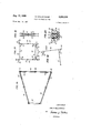
- Figure 14 is a top view of the frame construction of the ball returning element of the device of the invention.
- Figure 15 is a front view of a strut used for assembling the frame construction of the device of the invention.
- Figure 16 is a cross sectional view of a strut used for assembling the frame construction of the device of the invention.
- Figure 17 is a diagram of the frame construction shown in Figure 12;
- Figure 18 is another diagram of the side elevational view of the frame construction as shown in Figure 13;
- Figure 19 is a further diagram of the folded frame construction of the present invention.
- Figure 20 is a cross sectional view of the completely folded frame construction of the device of the invention.
- the ball training equipment is erected by means of a frame construction; its main constituent parts are 'two vertical struts 20 and 22 and two horizontal stru'ts'Zl and 23, as well as struts 24, attached at the upper points of intersection of strut 21 with struts 20 and 22, respectively, and.
- the horizontal bottom strut 23 supports a ball return surface 25 and the horizontal top strut 21 carried a main net 26, with its various connected further net portions, as specified in the following.
- the main net 26 is loosely suspended from the top strut 21. Those of its surface areas which are projecting outwardly of the lateral struts 20 and '22 are connected with the ends of strut 24.
- the main net 26 is also fastened with its bottom end to the ball return surface 25.
- a catch net 27 constituting a canopy is stretched.
- This catch net 27 has its lower edge fastened to the front side of main net 26.
- the tension of this catch net laterally, can be changed by rotating struts 24 about their pivotal connection with the vertical struts 20 and 22.
- top catch net 27 has its lower edge connected to the top of the main net and the catch net portions 28, 29 and 30, which are of varying heights, are suspended at only their top edge from the front face of the main net but are independent of each other.
- additional net portions may be added.
- Figure 2 indicates as an example, how these net portions are fastened with their top edge to main net 26 and how their bottom edges are hanging free, overlapping each other. It may be sufficient to fasten the net portions at the upper side corners.
- a continuous target tape 31 is installed in front or behind main net 26 in the vertical center from top to bottom. It is provided with marks, i.e. with letters or numbers; there is, however, also the possibility of dividing the target tape into several short sections, one for each net portion 28, 29 and 30, whereby the marking of the individual sections will subsequently follow towards the top.
- Another characteristic of the present invention is, that all rebounding surfaces in the area of net 26 and the net portions 28, 29 and 30 fastened thereto, are eliminated since all parts of the frame 20, 22, 21 and 23, 24 are located behind net 26 and net portions 28, 29 and 30. Therefore, a ball strongly hitting the net will bulge the net at the impacted spot, but will never touch the frame.
- the ball return surface 25 may comprise cloth, netting or elastic or hard material, and is provided with lateral roll-off edges 41. It reaches below the lowest part of net portion 30.
- the rear edge of the ball return surface is fastened stretchably to the horizontal bottom cross strut 23, supporting struts'33 and cross brace 32, and can be released.
- the ball return surface 25 extends forwardly onto a mat 34, where its lateral support struts 33 are connected by means of the cross brace 32, which enables stretching of the entire returner opposite to the frame.
- the mat is provided with a tee. This mat has several exchangeable surfaces, designed as a substitute for the lawn surface of a fairway and/or the rough (high grass).
- the frame should further meet the requirement of being capable of folding so as to form a small bundle
- All tubular frame struts 20 and 23 can be folded by means of a hinge 35 being installed in the middle of their length, allowing for the folding, so that they can be laid alongside of each other.
- a flat iron 36 is fixed for this purpose to the upper part of the tube, as shown in Figures 7 and 8, for the hinge of vertical strut 20.
- the flat iron will be enclosed by a forked link 37, mounted to the lower part of the tube, whereby parts 36 and 37 are hingedly connected by means of a pivot 38.
- This joint connection is secured by a security pin, inserted into hole 39 drilled through both parts 36 and 37, opposite pivot 38.
- tubular strut After removing this pin (not indicated in the drawings) the upper half of tubular strut (see left part of Figure 8) can be folded down alongside the bottom half of tubular strut.
- Pivot 38 for the hinge as shown in Fig ure 8 is eccentrically arranged, so as to allow for a close arrangement of both halves of the strut.
- struts 21 and 23 can be folded down to one half of their length by means of similar hinges 35.
- Vertical struts 20 and 22 are also divided a second time and at their separated ends provided with threads 40 and 40' of opposite direction. These ends are screwed into a threaded sleeve 42, joining the same and allowing for an adjustment of their length.
- the upper horizontal strut 21 is welded to the vertical struts 20 and 22, as indicated in Figure 10.
- This connection is provided with a disc 43 with a projecting catch 44.
- a turnable bushing 45 bear the slightly upwardly slanted strut.
- On its lower edge the bushing is provided with several notches which are engageable with the catch 44 to lock the bushing in position.
- a spring 46 located between the top of the bushing and a buffer of a screw-bolt permanently presses the bushing 45 downward- 1y.
- the supporting struts 33 of the ball return surface 25 are firmly connected with the horizontal bottom frame strut 23, as indicated in Figure 11.
- the struts themselves as well as the oonnecting front strut 32 are also provided with a hinge 35 in the middle of their length, so
- Figures 12 and 20 refer to another, very practical em bodiment and illustrate the folding-up of the frame.
- the example shows, as indicated in Figure 4, that the ball return surface 25 is tilted upwardly, the struts 24 are turned to the inside and then the upper frame half is folded down along the XX, and then again along the axis YY, thereby reducing the size of the frame to one quarter of its original size.
- FIG. 12 thru 20 provides a bundle of struts after being folded, which can be placed in the bag.
- the horizontal frame struts 21 and 23 and the supporting struts 33 of the ball returner are provided with hinges in their respective centers to make a folding possible.
- the vertical struts 20 and 22 consist of sections and can be stuck together at their joints.
- the suspension struts 24 are hinged to the point of intersection of struts 20 and 22 with the upper cross strut 21 and are kept in correct slanting position by struts 55.
- the horizontal bottom strut 23 is also hinged to the vertical struts 20 and 22.
- Connecting struts 56 are connected with horizontal struts 21 and 23 through a pivot and their free, forked ends can be connected with the vertical struts by means of slots in adequate height, and a pin so that the position illustrated in Figure 12 is received. Also the supporting struts 33 of the ball returner can be connected to the bottom ends of the vertical frame struts and 22 by means of such hinged connecting struts 57.
- the already mentioned additional connecting struts 55, 56 and 57 are of semi-cylindrical design or consist of channel iron and have, at least on a part of their length, such an inside diameter, that upon folding of the frame and when they are placed towards the frame strut bearing the pivot, these connecting struts will clasp around the frame strut in the provided length.
- the ball return surface 25, firmly attached to the frame elements 20 through 23 would interfere with this folding procedure; therefore it is removable.
- bushings have been provided on vertical struts 20 and 22, into which the ends of the supporting struts 33 of the ball returner can be placed and fastened by pins. After being drawn out of bushings, the struts can be folded at their hinges 35 and thereby will amount to half of their original length only.
- the front cross strut 32 can in this construction be drawn out and is shaped, for example, as a flat iron.
- the frame elements 20 through 23 can also be arranged slightly obliquely towards the front, in which case the footings 49 will be provided with sockets slightly deviating from the vertical line for the bottom ends of struts 20 and 22'.
- This design may be of advantage, because the catch net portions 28, 29 and 30, as described in previous paragraphs, suspended in various heights, are suspended isolatedly from the main net 26 and therefore can more easily and more completely bulge and wrap around the ball.
- the previously described roll-01f edges for the ball return surface can be of various designs.
- such edges can consist of loops standing upright and sewn on, into which a flat iron can be inserted.
- a ball-driving cage comprising a supporting frame having a pair of spaced forwardly inclined vertical struts interconnected adjacent the ends thereof by horizontal struts, a main net attached to the upper of said horizontal struts and spaced forwardly of said vertical struts, said main net having portions extending outwardly and forwardly of said frame, means on the top of said supporting frame diverging upwardly and forwardly of said frame for supporting said outwardly extending portions of said main net, a catch net suspended from said sup porting means and having its lower edge fastened to the front side of said main net, said catch net further comprising a plurality of net portions being suspended by their top edges from the front side of said main net, said net portions being arranged at various heights with the bottom parts of each of said net portions ovenlapping the next following lower portion, and a ball-return surface inclined downwardly from the lower end of said main net and extending forwardly thereof.
- a ball-driving cage as claimed in claim 1 with said supporting means comprising a pair of suspension struts, a pair of rotatable bushings on the upper ends of each of said vertical struts and provided with slots in the bottom faces thereof, one of said pair of suspension struts extending outwardly from each of said pair of bushings, a disc on the upper end of each of said vertical struts beneath said bushings, and a spring on each vertical strut urging said bushings against said discs, said catch net being suspended from said pair of suspension struts so as to form a canopy, said suspension struts also supporting said main net.
- a ball-driving cage as claimed in claim 1 with the struts comprising said supporting frame being provided in their respective central portions with hinge means whereby said frame can be folded up.
- each of said struts comprising said supporting frame being fork-shaped at one end and ending in a flat iron on the other end, said fiat iron and said fork being provided with holes of equal dimension, said fork engaging said flat iron, said fork and flat iron being secured by a security-pin bolt entering said holes.
- a ball-driving cage as described in claim 1, said sloped ball-return surface comprising a frame and a cover of elastic material, said cover being stretchably fastened upon said frame.
- said sloped ball-return surface comprising a frame and a cover of elastic material, said cover being fastened upon said frame, said frame being composed of a cross brace and a pair of hinged connecting struts, said connecting struts connecting said frame of said ball-return surface to said supporting frame supporting said nets, said supporting frame further comprising a pair of supporting struts and four propping struts, said supporting struts being hingedly fastened to the upper end of said vertical struts and supporting said suspension struts, said propping struts being fastened to the four corners of said frame construction so as to reinforce the structure of the same.
Landscapes
- Health & Medical Sciences (AREA)
- General Health & Medical Sciences (AREA)
- Physical Education & Sports Medicine (AREA)
- Handcart (AREA)
Description
Aug. 11, 1959 E. WALLSTEINER GOLF TRAINING DEVICE 4 SheetsSheet 1 Filed Jan. 14, 1957 //vv/v70R [WALD WALLSTE/NER A f/arneys Aug. 11, 1959 E. WALLSTEINER I GOLF TRAINING DEVICE 4 Sheets-Sheet 2 Filed Jan. 14, 1957 //v v/v 70R EWALD WALLSTEl/VER Arlo meys 1959 E. WALLSTEINER 2,899,208
GOLF TRAINING DEVICE 4 'SheetsSheet 3 Filed Jan. 14, 195'? l/WfA/TOR EPWILD WALLSTE/NER A Hameys Aug. 11, 1959 E. WALLSTEINER 2,899,208 GOLF TRAINING DEVICE Filed Jan. 14. 1957 4 Sheets-Sheet 4' ,4 Nor/rays a tun The present invention relates to a training device. More in particular the present invention relates to a training device for golf and similar sports and games involving the hitting of a ball or a similar object towards a goal or target.
The practice of golf or similar ball driving activities cannot always be carried out on the requisite playground. It is therefore known in the art to construct various training facilities purportedly suitable for exercising golf and similar sports and games indoors. It is thus known to construct devices consisting of a catch net adjustably stretched transversely to the tee and having lateral and oblique edges set towards the front and to equip these devices with a ball returning element inclined towards the tee. All these known facilities are, however, unsatisfactory and suifer from a number of disadvantages. The ideal training device must enable the player to execute the most forceful strokes on a very small space and even in a small corner of a room. The shots to be executed with an ideal training device must be carried out in exactly the same manner as on the outdoor practice field.
In the known devices, the hard stroke, performed at such a short distance will inevitably drive the ball against the net with such a force that the ball will rebound regardless of the fact whether the net is tensioned or resilient. In addition, all known training devices have several hard and unelastic areas upon the surface of the net or at the edges of the latter. If the ball is hit against one of these unelastic areas it will rebound with such vigor that the player may be hit by the ball and may be accordingly seriously hurt. Even a thorough padding of the conventional training devices has proved to be incapable of eliminating this danger.
It is therefore necessary to design the net of a training device in which the aforementioned disadvantages are to be avoided in such a manner that the net will entirely absorb and thereby eradicate the kinetic energy of the ball. Once this has been done, the ball will fall softly back to the floor. In addition, the fastening of the net must be devised in such a manner that any unelastic spots or edges causing the ball to rebound with vigor are entirely eliminated.
It is the general object of the present invention to provide for a training device for practising golf and similar sports and games wherein the practising conditions correspond to the conditions prevailing in practising the respective activity on the actual playground.
It is a particular object of the present invention to provide for a training device for practising golf and similar sports and games with which the most forceful and vigorous strokes can be practised.
It is another object of the present invention to provide for a training device for practising golf and similar sports and games with which the respective activity can be practised with a very small available space.
It is a further object of the present invention to provide for a training device for practising golf and similar sports and games with which the respective activity can be practised without endangering the practising person or any other person in the vicinity of the latter.
It is still another object of the present invention to provide for a training device for practising golf and similar sports and games which can be easily folded and transported.
These objects are achieved and the disadvantages adhering to the known training devices are avoided by the present invention comprising a first, adjustable stretch net and a second net mounted directly in front of the first net on the side facing the player. The second net consists of various net portions.
Directly in front of the adjustable, stretched net, on the side facing the player, a second net is mounted, consisting of various small net portions, arranged in various heights and partly overlapping each other towards the front side. They are preferably suspended at the top edge only and are not connected with each other. These nets are connected by means of a frame construction installed behind the nets and outside of the area in which these net portions are suspended; the frame is connected to the slanted ball returning area which extends underneath the nets.
If the net is constructed in the manner described above, every ball hit towards the main net must on its way be caught by one of the suspended net portions; there it becomes entangled, a fact which is essential to the functioning of the device of the present invention. 7
The present invention will be better understood upon the following detailed description of the accompanying drawings, wherein Figure 1 is a perspective front view of the training device of the invention;
Figure 2 is a side elevational view of the training device;
Figure 3 is a side elevational view of the upper portion of the device shown in Figure 2;
Figure 4 is a front view of the device wherein the ball return portion is folded upwardly;
Figure 5 is a side view of the device of Figure 4 with the ball return portion in play position;
Figure 6 is a side view and shows the upper portion of the device as shown in Figure 5;
Figure 7 is a detailed view of a strut connection of the device of the invention;
Figure 8 is a detailed view, partly in section of a strut connection of the device;
Figure 9 is another detailed view, partly in section of a strut connection of the device;
Figure 10 is still another detailed view, partly in section of a strut connection of the device;
Figure 11 is a further detailed view, partly in section of a strut connection of the device;
Figure 12 is an elevational front view of another embodiment of the frame construction of the device of the invention;
Figure 13 is a side view of the embodiment of the frame construction shown in Figure 12;
Figure 14 is a top view of the frame construction of the ball returning element of the device of the invention;
Figure 15 is a front view of a strut used for assembling the frame construction of the device of the invention;
Figure 16 is a cross sectional view of a strut used for assembling the frame construction of the device of the invention;
Figure 17 is a diagram of the frame construction shown in Figure 12;
Figure 18 is another diagram of the side elevational view of the frame construction as shown in Figure 13;
Figure 19 is a further diagram of the folded frame construction of the present invention;
Figure 20 is a cross sectional view of the completely folded frame construction of the device of the invention,
Referring now to the drawings somewhat more in particular the ball training equipment according to the invention is erected by means of a frame construction; its main constituent parts are 'two vertical struts 20 and 22 and two horizontal stru'ts'Zl and 23, as well as struts 24, attached at the upper points of intersection of strut 21 with struts 20 and 22, respectively, and.
which extend in upward direction and towards the front of the training device. The horizontal bottom strut 23 supports a ball return surface 25 and the horizontal top strut 21 carried a main net 26, with its various connected further net portions, as specified in the following. The main net 26 is loosely suspended from the top strut 21. Those of its surface areas which are projecting outwardly of the lateral struts 20 and '22 are connected with the ends of strut 24. The main net 26 is also fastened with its bottom end to the ball return surface 25.
Connected to the top ends of suspension struts 24 in front of the main net 26, a catch net 27 constituting a canopy is stretched. This catch net 27 has its lower edge fastened to the front side of main net 26. The tension of this catch net, laterally, can be changed by rotating struts 24 about their pivotal connection with the vertical struts 20 and 22.
It is a particular feature of this invention that the top catch net 27 has its lower edge connected to the top of the main net and the catch net portions 28, 29 and 30, which are of varying heights, are suspended at only their top edge from the front face of the main net but are independent of each other. Depending upon the height of net 26, additional net portions may be added. Figure 2 indicates as an example, how these net portions are fastened with their top edge to main net 26 and how their bottom edges are hanging free, overlapping each other. It may be sufficient to fasten the net portions at the upper side corners.
A continuous target tape 31 is installed in front or behind main net 26 in the vertical center from top to bottom. It is provided with marks, i.e. with letters or numbers; there is, however, also the possibility of dividing the target tape into several short sections, one for each net portion 28, 29 and 30, whereby the marking of the individual sections will subsequently follow towards the top.
Another characteristic of the present invention is, that all rebounding surfaces in the area of net 26 and the net portions 28, 29 and 30 fastened thereto, are eliminated since all parts of the frame 20, 22, 21 and 23, 24 are located behind net 26 and net portions 28, 29 and 30. Therefore, a ball strongly hitting the net will bulge the net at the impacted spot, but will never touch the frame.
The ball return surface 25 may comprise cloth, netting or elastic or hard material, and is provided with lateral roll-off edges 41. It reaches below the lowest part of net portion 30. The rear edge of the ball return surface is fastened stretchably to the horizontal bottom cross strut 23, supporting struts'33 and cross brace 32, and can be released. The ball return surface 25 extends forwardly onto a mat 34, where its lateral support struts 33 are connected by means of the cross brace 32, which enables stretching of the entire returner opposite to the frame. The mat is provided with a tee. This mat has several exchangeable surfaces, designed as a substitute for the lawn surface of a fairway and/or the rough (high grass).
The frame should further meet the requirement of being capable of folding so as to form a small bundle,
requiring little space only; therefore the various frame struts can only partly be welded together. They should not be constructed so as to be taken apart, because this tion. This can be achieved in different ways. One of the possibilities is shown in Figures 4 thru 11 of the accompanying drawings. a
All tubular frame struts 20 and 23 can be folded by means of a hinge 35 being installed in the middle of their length, allowing for the folding, so that they can be laid alongside of each other. A flat iron 36 is fixed for this purpose to the upper part of the tube, as shown in Figures 7 and 8, for the hinge of vertical strut 20. The flat iron will be enclosed by a forked link 37, mounted to the lower part of the tube, whereby parts 36 and 37 are hingedly connected by means of a pivot 38. This joint connection is secured by a security pin, inserted into hole 39 drilled through both parts 36 and 37, opposite pivot 38. After removing this pin (not indicated in the drawings) the upper half of tubular strut (see left part of Figure 8) can be folded down alongside the bottom half of tubular strut. Pivot 38 for the hinge, as shown in Fig ure 8 is eccentrically arranged, so as to allow for a close arrangement of both halves of the strut. In the same manner struts 21 and 23 can be folded down to one half of their length by means of similar hinges 35. Vertical struts 20 and 22 are also divided a second time and at their separated ends provided with threads 40 and 40' of opposite direction. These ends are screwed into a threaded sleeve 42, joining the same and allowing for an adjustment of their length.
The upper horizontal strut 21 is welded to the vertical struts 20 and 22, as indicated in Figure 10. This connection is provided with a disc 43 with a projecting catch 44. On this disc a turnable bushing 45 bear the slightly upwardly slanted strut. On its lower edge the bushing is provided with several notches which are engageable with the catch 44 to lock the bushing in position. A spring 46 located between the top of the bushing and a buffer of a screw-bolt permanently presses the bushing 45 downward- 1y. By means of this snapping catch connection not only the oblique position of the struts 24, pointing in outward direction can be changed and adjusted, but the same can also be turned towards the inside and there be secured, as shown by the dotted lines in Figure 4.
The lower free ends of vertical struts 20 and 22 are either set into slots in the floor or rest in footings 49, attached to the floor by means of screws. Said struts, as shown in Figure 5 in dotted lines, can be provided with supports 50, pointing backward, by which means anchoring to a wall can be effected, if necessary.
The supporting struts 33 of the ball return surface 25 are firmly connected with the horizontal bottom frame strut 23, as indicated in Figure 11. The struts themselves as well as the oonnecting front strut 32 are also provided with a hinge 35 in the middle of their length, so
that they can likewise be folded and laid alongside of each other. The connection of the bottom frame strut 23 with the vertical frame struts 20 and 22 will best be effected as shown in Figure 11, i.e. by welding an angular iron 51 onto struts 20 and 22 in adequate height, the rectangularly bent-off free end of which is provided with a slot or hole, serving as a catch for pivot 52, installed at the ends of tube 23, upon the outside of which a screwnut 53 may be fastened and which, when tightened on both sides of cross strut 23, will firmly connect it with the angular iron 51 and thereby also with both vertical struts '20 and 22. Provided the supporting struts 33 run towards each other in front, as indicated in Figure 6, the complete frame will have an approximate three-point support through footings 49 and cross strut 32, which provide a firm and stable footing.
Figures 12 and 20 refer to another, very practical em bodiment and illustrate the folding-up of the frame.
The example shows, as indicated in Figure 4, that the ball return surface 25 is tilted upwardly, the struts 24 are turned to the inside and then the upper frame half is folded down along the XX, and then again along the axis YY, thereby reducing the size of the frame to one quarter of its original size.
The example shown in Figures 12 thru 20 provides a bundle of struts after being folded, which can be placed in the bag. Here also the horizontal frame struts 21 and 23 and the supporting struts 33 of the ball returner are provided with hinges in their respective centers to make a folding possible. The vertical struts 20 and 22 consist of sections and can be stuck together at their joints. The suspension struts 24 are hinged to the point of intersection of struts 20 and 22 with the upper cross strut 21 and are kept in correct slanting position by struts 55. The horizontal bottom strut 23 is also hinged to the vertical struts 20 and 22. Connecting struts 56, the design of which is indicated in Figures and 16, are connected with horizontal struts 21 and 23 through a pivot and their free, forked ends can be connected with the vertical struts by means of slots in adequate height, and a pin so that the position illustrated in Figure 12 is received. Also the supporting struts 33 of the ball returner can be connected to the bottom ends of the vertical frame struts and 22 by means of such hinged connecting struts 57. The above mentioned struts 55, 56 and 57 will at their connecting points be unfastened for transportation, so that the suspension struts 24 will be hinged downwards; connecting irons 56 will be arranged alongside of horizontal struts 21 and 23 and the latter will then fold their hinges 35 in such manner that the top hinge is located at the bottom, the bottom hinge located on top, thereby resulting in the position illustrated in Figure 14. Then the vertical struts are taken apart at their joints 58 and both halves of the frame are placed side by side, whereby a bundle is obtained containing all tubular struts of the frame structure held closely together, as illustrated in Figure 20. The entire material can then be stored and transported in a bag (indicated by dotted lines).
The already mentioned additional connecting struts 55, 56 and 57 are of semi-cylindrical design or consist of channel iron and have, at least on a part of their length, such an inside diameter, that upon folding of the frame and when they are placed towards the frame strut bearing the pivot, these connecting struts will clasp around the frame strut in the provided length.
The ball return surface 25, firmly attached to the frame elements 20 through 23 would interfere with this folding procedure; therefore it is removable. For this purpose bushings have been provided on vertical struts 20 and 22, into which the ends of the supporting struts 33 of the ball returner can be placed and fastened by pins. After being drawn out of bushings, the struts can be folded at their hinges 35 and thereby will amount to half of their original length only. The front cross strut 32 can in this construction be drawn out and is shaped, for example, as a flat iron.
As illustrated in Figure 13 the frame elements 20 through 23 can also be arranged slightly obliquely towards the front, in which case the footings 49 will be provided with sockets slightly deviating from the vertical line for the bottom ends of struts 20 and 22'. This design may be of advantage, because the catch net portions 28, 29 and 30, as described in previous paragraphs, suspended in various heights, are suspended isolatedly from the main net 26 and therefore can more easily and more completely bulge and wrap around the ball.
The previously described roll-01f edges for the ball return surface can be of various designs. In case elastic material is used for the ball return surface 25, such edges can consist of loops standing upright and sewn on, into which a flat iron can be inserted.
It will be understood that this invention is susceptible to modification in order to adapt it to different usages and conditions, and, accordingly, it is desired to compre- 6 hend such modifications this invention as may fall within the scope of the appended claims.
What I claim is:
1. A ball-driving cage comprising a supporting frame having a pair of spaced forwardly inclined vertical struts interconnected adjacent the ends thereof by horizontal struts, a main net attached to the upper of said horizontal struts and spaced forwardly of said vertical struts, said main net having portions extending outwardly and forwardly of said frame, means on the top of said supporting frame diverging upwardly and forwardly of said frame for supporting said outwardly extending portions of said main net, a catch net suspended from said sup porting means and having its lower edge fastened to the front side of said main net, said catch net further comprising a plurality of net portions being suspended by their top edges from the front side of said main net, said net portions being arranged at various heights with the bottom parts of each of said net portions ovenlapping the next following lower portion, and a ball-return surface inclined downwardly from the lower end of said main net and extending forwardly thereof.
2. A ball-driving cage as claimed in claim 1 with said main net being adjustably stretchable laterally thereof.
3. A ball-driving cage as claimed in claim 1 with said supporting means comprising a pair of suspension struts, a pair of rotatable bushings on the upper ends of each of said vertical struts and provided with slots in the bottom faces thereof, one of said pair of suspension struts extending outwardly from each of said pair of bushings, a disc on the upper end of each of said vertical struts beneath said bushings, and a spring on each vertical strut urging said bushings against said discs, said catch net being suspended from said pair of suspension struts so as to form a canopy, said suspension struts also supporting said main net.
4. A ball-driving cage as claimed in claim 1 with the struts comprising said supporting frame being provided in their respective central portions with hinge means whereby said frame can be folded up.
5. A ball-driving cage as described in claim 4, with each of said struts comprising said supporting frame being fork-shaped at one end and ending in a flat iron on the other end, said fiat iron and said fork being provided with holes of equal dimension, said fork engaging said flat iron, said fork and flat iron being secured by a security-pin bolt entering said holes.
6. A ball-driving cage as described in claim 1, said sloped ball-return surface comprising a frame and a cover of elastic material, said cover being stretchably fastened upon said frame.
7. A ball-driving cage as described in claim 4, said sloped ball-return surface comprising a frame and a cover of elastic material, said cover being fastened upon said frame, said frame being composed of a cross brace and a pair of hinged connecting struts, said connecting struts connecting said frame of said ball-return surface to said supporting frame supporting said nets, said supporting frame further comprising a pair of supporting struts and four propping struts, said supporting struts being hingedly fastened to the upper end of said vertical struts and supporting said suspension struts, said propping struts being fastened to the four corners of said frame construction so as to reinforce the structure of the same.
References Cited in the file of this patent UNITED STATES PATENTS 1,407,109 Winkley Feb. 21, 1922 1,540,670 Vidmer June 2, 1925 2,123,195 Middleton July 12, 1938
Publications (1)
| Publication Number | Publication Date |
|---|---|
| US2899208A true US2899208A (en) | 1959-08-11 |
Family
ID=3448034
Family Applications (1)
| Application Number | Title | Priority Date | Filing Date |
|---|---|---|---|
| US2899208D Expired - Lifetime US2899208A (en) | Wallsteiner |
Country Status (1)
| Country | Link |
|---|---|
| US (1) | US2899208A (en) |
Cited By (25)
| Publication number | Priority date | Publication date | Assignee | Title |
|---|---|---|---|---|
| US3100115A (en) * | 1961-05-11 | 1963-08-06 | James C Breneman | Portable backstop for arrows |
| US3218070A (en) * | 1960-03-22 | 1965-11-16 | Rae Crowther Co | Foldable football practice apparatus |
| US3455554A (en) * | 1965-10-19 | 1969-07-15 | Hamlin Products Inc | Air gun shot arresting target |
| US3989246A (en) * | 1973-12-14 | 1976-11-02 | Brown Alvin I | Tennis practice system |
| US4243221A (en) * | 1976-08-24 | 1981-01-06 | Ferreira Godinho Manuel | Training device for practicing the service in tennis |
| US4286786A (en) * | 1978-05-18 | 1981-09-01 | Papadopoulos Andreas T | Soccer training goal |
| US4615528A (en) * | 1985-02-08 | 1986-10-07 | York Henry A | Soccer training device |
| US4723780A (en) * | 1986-10-16 | 1988-02-09 | Vinzetta Jerry P | Golf practice device |
| US5108102A (en) * | 1990-09-28 | 1992-04-28 | Neil Logan | Golf ball drive practice device |
| US5251885A (en) * | 1990-09-28 | 1993-10-12 | Neil Logan | Golf ball drive practice device |
| FR2716809A1 (en) * | 1994-03-02 | 1995-09-08 | Bosc Emmanuel | Net to stop arrow used in archery |
| US6319145B1 (en) | 1997-12-08 | 2001-11-20 | Terry J. Coughlan | Game element retrieval |
| US20030125121A1 (en) * | 2001-12-27 | 2003-07-03 | Rhee Yong Su | Golf short game training, practice and contest game kit |
| US20040038759A1 (en) * | 2002-08-23 | 2004-02-26 | Kuzia Stanley J. | Free-standing partitioned goal and process of using the goal |
| US6793594B1 (en) | 2003-03-27 | 2004-09-21 | Athletic Training Equipment Company, Inc. | Sports practice net |
| US6889982B1 (en) * | 2001-07-05 | 2005-05-10 | Bolo Usa | Indoor/outdoor game |
| WO2005097272A1 (en) * | 2004-04-07 | 2005-10-20 | Harry Henry Joseph Wright | Apparatus for practicing golf |
| US20060030755A1 (en) * | 2000-10-19 | 2006-02-09 | Applied Medical Resources Corporation | Surgical access apparatus and method |
| US20060199658A1 (en) * | 2004-03-05 | 2006-09-07 | Leonard Willie B | Multi-pocket golf net assembly with multiple target sheath configurations |
| US20070132187A1 (en) * | 2005-12-09 | 2007-06-14 | George Byram | Paintball targeting system |
| US20080023916A1 (en) * | 2006-07-28 | 2008-01-31 | Remillard Martin E | Paintball deflection and collection apparatus |
| US8216083B1 (en) | 2010-10-29 | 2012-07-10 | Masucci G Thomas | Golf practice apparatus |
| US20130035173A1 (en) * | 2011-04-22 | 2013-02-07 | Joseph Yosup Lee | Apparatus and method for catching a golf ball |
| US9573033B2 (en) | 2012-10-15 | 2017-02-21 | Scott T. Surbrook | Returning goal system |
| US10335660B1 (en) * | 2017-07-04 | 2019-07-02 | Rosario Pizzirusso | Ball return device |
Citations (3)
| Publication number | Priority date | Publication date | Assignee | Title |
|---|---|---|---|---|
| US1407109A (en) * | 1919-10-25 | 1922-02-21 | Erastus E Winkley | Golf apparatus |
| US1540670A (en) * | 1925-06-02 | jdhdvhj | ||
| US2123195A (en) * | 1932-11-07 | 1938-07-12 | William V Middleton | Game apparatus |
-
0
- US US2899208D patent/US2899208A/en not_active Expired - Lifetime
Patent Citations (3)
| Publication number | Priority date | Publication date | Assignee | Title |
|---|---|---|---|---|
| US1540670A (en) * | 1925-06-02 | jdhdvhj | ||
| US1407109A (en) * | 1919-10-25 | 1922-02-21 | Erastus E Winkley | Golf apparatus |
| US2123195A (en) * | 1932-11-07 | 1938-07-12 | William V Middleton | Game apparatus |
Cited By (34)
| Publication number | Priority date | Publication date | Assignee | Title |
|---|---|---|---|---|
| US3218070A (en) * | 1960-03-22 | 1965-11-16 | Rae Crowther Co | Foldable football practice apparatus |
| US3100115A (en) * | 1961-05-11 | 1963-08-06 | James C Breneman | Portable backstop for arrows |
| US3455554A (en) * | 1965-10-19 | 1969-07-15 | Hamlin Products Inc | Air gun shot arresting target |
| US3989246A (en) * | 1973-12-14 | 1976-11-02 | Brown Alvin I | Tennis practice system |
| US4243221A (en) * | 1976-08-24 | 1981-01-06 | Ferreira Godinho Manuel | Training device for practicing the service in tennis |
| US4286786A (en) * | 1978-05-18 | 1981-09-01 | Papadopoulos Andreas T | Soccer training goal |
| US4615528A (en) * | 1985-02-08 | 1986-10-07 | York Henry A | Soccer training device |
| US4723780A (en) * | 1986-10-16 | 1988-02-09 | Vinzetta Jerry P | Golf practice device |
| US5108102A (en) * | 1990-09-28 | 1992-04-28 | Neil Logan | Golf ball drive practice device |
| US5251885A (en) * | 1990-09-28 | 1993-10-12 | Neil Logan | Golf ball drive practice device |
| FR2716809A1 (en) * | 1994-03-02 | 1995-09-08 | Bosc Emmanuel | Net to stop arrow used in archery |
| US6319145B1 (en) | 1997-12-08 | 2001-11-20 | Terry J. Coughlan | Game element retrieval |
| US20060030755A1 (en) * | 2000-10-19 | 2006-02-09 | Applied Medical Resources Corporation | Surgical access apparatus and method |
| US6889982B1 (en) * | 2001-07-05 | 2005-05-10 | Bolo Usa | Indoor/outdoor game |
| US20030125121A1 (en) * | 2001-12-27 | 2003-07-03 | Rhee Yong Su | Golf short game training, practice and contest game kit |
| US6905418B2 (en) * | 2001-12-27 | 2005-06-14 | Yong Su Rhee | Golf short game training, practice and contest game kit |
| US6811501B2 (en) * | 2002-08-23 | 2004-11-02 | International Bullseye Sports Association, Llc | Free-standing partitioned goal and process of using the goal |
| US20040038759A1 (en) * | 2002-08-23 | 2004-02-26 | Kuzia Stanley J. | Free-standing partitioned goal and process of using the goal |
| US20040191738A1 (en) * | 2003-03-27 | 2004-09-30 | Eugene Grant | Sports practice net |
| US6793594B1 (en) | 2003-03-27 | 2004-09-21 | Athletic Training Equipment Company, Inc. | Sports practice net |
| US20060199658A1 (en) * | 2004-03-05 | 2006-09-07 | Leonard Willie B | Multi-pocket golf net assembly with multiple target sheath configurations |
| WO2005097272A1 (en) * | 2004-04-07 | 2005-10-20 | Harry Henry Joseph Wright | Apparatus for practicing golf |
| US7494128B2 (en) * | 2005-12-09 | 2009-02-24 | George Byram | Paintball targeting system |
| US20080023154A1 (en) * | 2005-12-09 | 2008-01-31 | George Byram | Paintball Targeting System |
| US20070132187A1 (en) * | 2005-12-09 | 2007-06-14 | George Byram | Paintball targeting system |
| US7980561B2 (en) | 2005-12-09 | 2011-07-19 | George Byram | Paintball targeting system |
| US8469365B2 (en) | 2005-12-09 | 2013-06-25 | George Byram | Paintball targeting system |
| US20080023916A1 (en) * | 2006-07-28 | 2008-01-31 | Remillard Martin E | Paintball deflection and collection apparatus |
| US8216083B1 (en) | 2010-10-29 | 2012-07-10 | Masucci G Thomas | Golf practice apparatus |
| US20130035173A1 (en) * | 2011-04-22 | 2013-02-07 | Joseph Yosup Lee | Apparatus and method for catching a golf ball |
| US8876619B2 (en) * | 2011-04-22 | 2014-11-04 | Joseph Yosup Lee | Apparatus and method for catching a golf ball |
| US9399162B2 (en) | 2011-04-22 | 2016-07-26 | Joseph Yosup Lee | Apparatus and method of catching a golf ball |
| US9573033B2 (en) | 2012-10-15 | 2017-02-21 | Scott T. Surbrook | Returning goal system |
| US10335660B1 (en) * | 2017-07-04 | 2019-07-02 | Rosario Pizzirusso | Ball return device |
Similar Documents
| Publication | Publication Date | Title |
|---|---|---|
| US2899208A (en) | Wallsteiner | |
| US8900074B1 (en) | Reconfigurable sports training device | |
| US3602504A (en) | Ball training and game device | |
| US3836144A (en) | Portable projectile return apparatus | |
| US5562288A (en) | Portable elastic sports goal | |
| US4068846A (en) | Place-kicking football receiving target | |
| US3752476A (en) | Projectile return apparatus | |
| US5558338A (en) | Game assembly for multiple sports usage | |
| US6659892B2 (en) | Kickback training goal | |
| US9682300B2 (en) | Sports practicing system and method | |
| US5823885A (en) | Portable personal driving range and all purpose sporting net | |
| US4750744A (en) | Golf practice apparatus | |
| US4160549A (en) | Tennis serve training and practice device | |
| US4674744A (en) | Batting practice assembly | |
| US5007638A (en) | Pitchback device for athletic practice | |
| US5054791A (en) | Background shield for soccer practice | |
| US6659893B1 (en) | Volleyball training apparatus | |
| AU2017207451B2 (en) | Ball return device and system | |
| WO1993001866A1 (en) | Net support structure | |
| US8100784B2 (en) | Lacrosse goal extension net | |
| US20130040762A1 (en) | Tennis, golf and basketball training device having an adjustable hoop | |
| US4533138A (en) | Multiple sport training device | |
| US5553863A (en) | Flexible two-sided multiple-sport goal | |
| US3540734A (en) | Golfing target | |
| US11819747B2 (en) | Rebounding device for sports ball |