US2852257A - Work handling apparatus - Google Patents
Work handling apparatus Download PDFInfo
- Publication number
- US2852257A US2852257A US539173A US53917355A US2852257A US 2852257 A US2852257 A US 2852257A US 539173 A US539173 A US 539173A US 53917355 A US53917355 A US 53917355A US 2852257 A US2852257 A US 2852257A
- Authority
- US
- United States
- Prior art keywords
- jaw
- clip
- conveyor
- pivot
- Prior art date
- Legal status (The legal status is an assumption and is not a legal conclusion. Google has not performed a legal analysis and makes no representation as to the accuracy of the status listed.)
- Expired - Lifetime
Links
Images

Classifications
-
- B—PERFORMING OPERATIONS; TRANSPORTING
- B41—PRINTING; LINING MACHINES; TYPEWRITERS; STAMPS
- B41F—PRINTING MACHINES OR PRESSES
- B41F23/00—Devices for treating the surfaces of sheets, webs, or other articles in connection with printing
- B41F23/04—Devices for treating the surfaces of sheets, webs, or other articles in connection with printing by heat drying, by cooling, by applying powders
- B41F23/044—Drying sheets, e.g. between two printing stations
- B41F23/0443—Drying sheets, e.g. between two printing stations after printing
- B41F23/0446—Wicket conveyors
Definitions
- This invention relates to work handling apparatus, particularly an apparatus for handling wet prints as delivered from a printing machine.
- An object of the invention is to provide for handling prints of the above character in a manner so as to materially reduce the distance of travel of the prints to provide for the drying thereof.
- Another object of the invention is to provide for handling prints of the above character in a manner so as to materially increase the number of prints which may be handled for a certain length of conveyor.
- Another object of the invention is to provide an apparatus of the above character having work gripping clips which will be so constructed as to be moved to open position by the work and self-closing on the work when in a certain position.
- Another object of the invention is to provide in an apparatus of the above character a conveyor having work gripping clips which may be readily secured in position on a conveyor without the use of bolts, screws, rivets, and like fastening means.
- a more specific object is to provide a conveyor in which the work-engaging clips are pressed steel stamping.
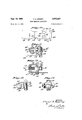
- Figure 1 is a view partially in section of an apparatus for handling wet prints, showing one embodiment of the invention
- Figure 2 is a side elevational view of one of the clips of Figure 1 shown attached to a link of the conveyor chain;
- Figure 3 is a similar view and showing the relation of the print releasing mechanism with the cam for operating the same;.
- Figure 4 is a plan view of a portion of the conveyor of Figure 1, showing the clip of Figure 2 attached thereto;
- Figure 8 is a perspective view of a roller forming part' of the gate release mechanism
- Figure 9 is a perspective view of a fastener employed for securing a clip to the conveyor chain
- Figure 10 is a plan view of a sheet metal stamping from which the body of the clip of Figure 6 may be made;
- Figure 11 is a side elevational view of a modified clip
- Figure 12 is a plan view of the clip of Figure 11;
- Figure 13 is a side elevational view of a further modified clip.
- Figure 14 is a front end view of the clip of Figure 13.
- the apparatus includes a roller chain type conveyor which carries a plurality of equally spaced print gripping elements which are arranged to be moved to open relation by the action ofthe prints inserted therein and self-closing on the prints.
- the work is discharged from the printing machine on to a belt conveyor which is caused to travel at greater speed than the' speed of delivery of the print from the printing area of the printing machine.
- the greater speed of the belt con-' veyor will impart a propelling-like action to the print toward a registered print-gripping element or clip for the leading edge thereof to strike the gate of'the clip with a sutficient force to move and push past the same.
- the gate will drop by gravity to engage the print and hold the same against Withdrawal.
- the belt conveyor which is mounted for swinging movement will swing downwardly and the chain conveyor willmove a distance to clear the print from the belt conveyor and move a clip carrying link in position to register a clip or clips with the belt conveyor upon its return to print receiving position.
- the print last lodged in a clip or clips will be moved in a suspended relation at the lower stretch of the chain conveyor to the location of print discharge.
- the print-carryingclips may be opened by gravity action to release the print and/or the clips.
- the apparatus is particularly adapted to be used in connection with a screen-printing machine wherein the speed of the machine is dependent to a great degree upon the speed at which the prints may be removed from the printing machine.
- the clips 11 each comprise a sheet metal U-shape body (see Figure ,6) having a fixed jaw 13 and an oppositely disposed arm or channel section 14 which are integrally joined by a flat bridge 15.
- the corners at the junction of the bridge 15 with the jaw 13 and section 14 are reinforced with ribs or fillets 16 which are raised from the stock of the body.
- the inner edges 17 of side walls 18 of the channel section engage against the inner side of bridge 15.
- the side walls are pierced with aligned openings 19 and aligned openings 20.
- a depressionll is provided on the inner side of the jaw 13.
- the body of the clip is preferably made of a metal stamping and may be fabricated from a sheet metal blank 22 shown in Figure 10, which may be first bent along brokenlines 23 into 3 channel section 14 and then bent at the portions enclosed between the broken lines 24 and 25 into a U-shape.
- each clip is. made of a plurality of sheet metal stampings and comprise a plurality of side-by-side flat plates or gates 27 which are positionedbetween the. channel side-walls 18 and are rockably mounted for free movementon a pivot 28 which. is supported and secured in the openings :19.
- the work or print-engaging edge of each gate extends on a curvature which is serrated at 29, and the upper outer edge adjacent the pivot 28 is notchedto form an abutment 30.
- a gate tripping or release mechanism 31 comprises a wire bent int-othe form shown in Figure 7 to pro vide a pivot section 32 which is journalled in openings'2tl, a section which extends from opening 20on a downward slant and bent at right angles at 33 to extend across the abutments .30and thence at right angles to provide an operating arm34 extending along the opposite side wall 18, said arm being provided with an arcuate out of-line portion 35 to provide a clearance for the end portion of 32 which projects beyond the adjacent side 18.
- a split tubular cylinder 36 (see Figure 8) embraces the section 33 and is adaptedto engage abutments .30.
- the gate engaged portion of the print will tend to be deformed into recess 21 and provide for a more secure grip by the gates on the print.
- the clips 11 are attached to the chains 37 of the con-' veyor 12 by means of fiat metal bars 38 (see Figure 4) which 'are rectangular in-cross section and extend crosswise from one chain 37 to the other chain 37.
- the barreceiving links have ears 40 to which the ends of the bars are attached by rivets 41 or other suitable fastener.
- the bars 38 are equally spaced along the chains, and the number or distance of spacing between bars is dependent upon the characteristic of the work. In the present instance the bars are shown (in Figure 1) uniformly spaced apart. This particular spacing is, however, merely illustrative and may be greater or less depending upon specific condition, such as speed of printing machine, length of print, type of paper, and other peculiarities of the art.
- the bridge 15 is positioned in abutting relation against the bar 38 and is secured in place by a clamp fastener 42 (see Figure 9).
- the fastener is in the form of a rectangular fiat plate 43 made of sheet metal and has a pair of hook-like lugs 44 at one longitudinal edge and a similar pair but initially unbent lugs 45 at the other longitudinal edge.
- the clamp 42 is positioned against the side of the bar opposite the clip with the bent lugs 44 extending over the bar into engagement with the bridge 15 of the clip.
- the unbent lugs 45 are then bent over and into firm engagement with the 4. said bridge 15, the lugs 44 being additionally squeezed into firm engagement with the bridge 15.
- FIGS 11 and 12 I have shown a modified construction of clip which comprises a body 46 providing a relatively stationary jaw 47 and effectively a channel section comprising, spaced arms 48, and lugs 49 which are attached directly by rivets 50 to the ears 40 of the clip-receiving links of the chains 37.
- a plurality of gates 51 are positioned between the arms 48 and are rockably supported on a pivot 52 fixed to said arms. The pivot is likewise positioned at a location forward of the point of engagement of the gates 51 with the jaw. The gates form the movablejaw and are gravity urged into engagement with the jaw 47.
- the gate tripping mechanism 31' is substantially similar to that previously described having a pivot section 32 which is j-ournalled in openings 20 with a section extending therefrom along the side of one arm 48, then bentat right angles at 33 to extend across the upper edge of the gates which .provides an abutment forward of the pivot 52, then bent at right angles to provide an operating arm'34' extending along and beyond the clip. It will be apparent from Figure 11 that in moving arm 34' upwardly about pivot 32, the section 33' will engage and swing gates 51 to open position.
- the movable jaw of the'clip is a sphere 53 held between a fixed jaw 54 and channel section or spaced arms 55 converging outwardly toward each other.
- the jaw 54 provides the stationary jaw of the clamp, and the channel section 55 has a top and side flanges or walls 56 to retain the ball 53 captive within the clip body but providing sufficient clearance forfree movement of said ball .53..
- the above clip is made of a metal stampingandprovided with spaced lugs 57 to be fastened by rivets 58 tothe cars 40 of the links of chains 37.
- the conveyor chains 37 ( Figure 1) are trained at one end thereof over idler sprocket gears 59 and at the other end over driven sprocket gears (not shown ⁇ .
- the drive will be necessarily intermittent and coordinated with the timing of the printing machine to index a clip-carrying link in register to receive a print from the conveyor 10.
- the drive may be conventional and include at Geneva motion mechanism. of known form.
- the conveyor 10 is caused to move sufiiciently fast so that upon the print being free of the printing mechanism (not shown), it will be advanced or propelled toward the properly registered clips 11 with a sufiicient force or momentum for its leading edge to strike the gates 27 and swing the same to pass thereby.
- the gates 27 under action of gravity will swing into engagement with the print and hold the same against the jaw 13.
- the conveyor 10 which is swingably mounted is caused to be swung downwardly to a position indicated in broken lines a distance sufficient to clear the print from the conveyor 10.
- the'spacing between bars 38 is dependent upon the characteristic of the work and amount of travel of the clips 11 about sprocket 59 'to clear a print from conveyor 10.
- the movement of the conveyor 12 to clear the print from the conveyor 10 will move the next in line clip in position to receiveaprint from the conveyor 10 which hasbeen-located in print loading position.
- the prints will be carried by the lower stretch of the chains 37 to the delivery end of conveyor 12 to be released therefrom by means of a cam'block 68 (see Figure 3) which is at a position adjacent the lower stretch of chains in-the path of movement of the arm 34 of the gate release mechanism 31.
- the arm 34 will be swung by-the cam 60'to swing roller 36 in a counter-clockwise direction to swing gates 27 out of engagement with the print-held thereby.
- a print and the like gripping clip comprising a U-shaped body having a stationary jaw and a channel section disposed opposite said jaw in spaced relation therewith, a plurality of flat plates having print gripping edges thereon, said plates being pivotally mounted side by side on said channel between the walls thereof and each having an abutment at the outer edge thereof adjacent the pivot thereof, said plates normally extending into engagement with said jaw, and a release mechanism pivoted on said channel section and having a part extending from said pivot across said abutments and an operating handle movable to swing said part about said pivot into engagement with said abutments to move said plates out of engagement with said jaw.
- a conveyor for handling wet prints as delivered from a printing machine comprising spaced flexible members, a bar extending laterally from one flexible member to the other and secured thereto, a print gripping clip carried by said bar, said clip having a bridge abutting against said bar, a clamp plate for securing said clip to said bar, said clamp plate engaging the opposite side of the bar and having fastening lugs extending over said bar into engagement with said bridge.
- a conveyor for handling wet prints as delivered from a printing machine comprising an endless flexible member, a print gripping clip carried by said flexible member, said clip having a U-shaped body provided with a stationary jaw and a channel section disposed opposite said jaw in spaced relation therewith, said channel section and said jaw being connected by a flat bridge, a movable jaw carried within said channel section, said movable jaw having the larger portion of its mass located at a position inwardly of the outer end of said channel section, said movable jaw being movable to print gripping relation with said stationary jaw by gravity action in one position of the clip, and means extending from said flexible member into abutting relation with said bridge, and fastening means for securing said first means and said bridge to each other and a release mechanism pivoted on said channel section and having a part extending from said pivot across said movable jaw to engage and swing said movable jaw and a handle to move said part and swing the movable jaw away from the fixed jaw.
- a print and the like gripping clip comprising a U-shaped body having a stationary jaw and a channel section disposed opposite said jaw in spaced relation therewith, a movable jaw carried within said channel section, said movable jaw having the larger portion of its mass located at a position inwardly of the outer ends of said channel section, said movable jaw being movable into print gripping relation with said stationary jaw by gravity action in one position of the clip a release mechanism pivoted on said channel section and having a part extending from said pivot across said movable jaw to engage and swing said movable jaw and a handle to move said part and swing the movable jaw away from the fixed jaw.
- a print and the like gripping clip comprising a U-shaped body providing a stationary jaw and an arm opposite said jaw spaced therefrom, a movable jaw pivoted on said arm for rockable movement toward said movable jaw to grip a print between said jaws, a release mechanism pivoted on said arm and having a part extending for engagement with said movable jaw and a handle to move said part to swing the movable jaw out of engagement with said fixed jaw.
- a print and the like gripping clip comprising a U-shaped body providing a stationary jaw and an arm opposite said jaw spaced therefrom, a movable jaw pivoted on said arm for rockable movement toward said fixed jaw to grip a print between said jaws, a release mechanism pivoted on said arm on an axis parallel to the pivot of said movable jaw and having a part extending from said pivot across said movable jaw, said movable jaw having an abutment at the outer edge thereof adjacent its pivot for engagement with said part and a handle to move said part to swing the movable jaw out of engagement with said fixed jaw.
- a print and the like gripping clip according to claim 5 wherein said jaw and arm are made from a single piece of sheet metal and said jaw and arm are joined by a flat bridge forming corners at the junctions of the bridge with the channel section and jaw, said corners being provided with reinforcing fillets raised from the stock at said corners.
Description
Sept. 16, 1958 i P. A. SPERRY 2,852,257 j WORK HANDLING APPARATUS Filed Oct. 7, 1955 2 Sheets-Sheet l INVENTOR. Pa 14/ 045/9617 y HTTORNEYs.
Sept. 16, 1958 P. A. SPERRY 2,352,257
' WORK HANDLING APPARATUS Filed Oct. 7, 1955 2 Sheets-Sheet 2 IN V EN TOR.
A T 'TORNEYS.
United States Patent WORK HANDLING APPARATUS Paul A. Sperry, New Haven, Conn.
Application October 7, 1955, Serial No. 539,173
a 8 Claims. (Cl. 27179) This invention relates to work handling apparatus, particularly an apparatus for handling wet prints as delivered from a printing machine.
This application is a continuation in part of an application filed August 4, 1953, Serial No. 372,367, now Patent No. 2,788,210, issued April 9, 1957.
In certain type printing, as for example screen printing, individual sheets are printed and discharged from the printing area of the machine with the ink in a wet condition. Heretofore, the usual practice was to deliver the wet sheets or prints end to end on a traveling endless belt conveyor of a length to permit the prints to dry while moving from one end of the conveyor to the other. The length of the belt for any particular speed of travel thereof is predetermined by the time required for the prints to dry. Thus, as the speed of the printing machine is increased, the length of the belt must likewise be increased so as to provide the time element required for drying the prints. The length of the belt is for practical reasons limited, which as a consequence limits the speed at which the printing machine may be operated.
An object of the invention is to provide for handling prints of the above character in a manner so as to materially reduce the distance of travel of the prints to provide for the drying thereof.
Another object of the invention is to provide for handling prints of the above character in a manner so as to materially increase the number of prints which may be handled for a certain length of conveyor.
Another object of the invention is to provide an apparatus of the above character having work gripping clips which will be so constructed as to be moved to open position by the work and self-closing on the work when in a certain position.
Another object of the invention is to provide in an apparatus of the above character a conveyor having work gripping clips which may be readily secured in position on a conveyor without the use of bolts, screws, rivets, and like fastening means.
A more specific object is to provide a conveyor in which the work-engaging clips are pressed steel stamping.
With these and other objects in view, the invention consists of certain novel features of construction as will be more fully described and particularly pointed out in the appended claims.
In the accompanying drawings:
Figure 1 is a view partially in section of an apparatus for handling wet prints, showing one embodiment of the invention;
Figure 2 is a side elevational view of one of the clips of Figure 1 shown attached to a link of the conveyor chain;
Figure 3 is a similar view and showing the relation of the print releasing mechanism with the cam for operating the same;.
Figure 4 is a plan view of a portion of the conveyor of Figure 1, showing the clip of Figure 2 attached thereto;
ice
nism;
Figure 8 is a perspective view of a roller forming part' of the gate release mechanism;
Figure 9 is a perspective view of a fastener employed for securing a clip to the conveyor chain;
Figure 10 is a plan view of a sheet metal stamping from which the body of the clip of Figure 6 may be made;
Figure 11 is a side elevational view of a modified clip;
Figure 12 is a plan view of the clip of Figure 11;
Figure 13 is a side elevational view of a further modified clip; and
Figure 14 is a front end view of the clip of Figure 13.
The apparatus according to the invention includes a roller chain type conveyor which carries a plurality of equally spaced print gripping elements which are arranged to be moved to open relation by the action ofthe prints inserted therein and self-closing on the prints. The work is discharged from the printing machine on to a belt conveyor which is caused to travel at greater speed than the' speed of delivery of the print from the printing area of the printing machine. Upon the release of the print from the printing mechanism, the greater speed of the belt con-' veyor will impart a propelling-like action to the print toward a registered print-gripping element or clip for the leading edge thereof to strike the gate of'the clip with a sutficient force to move and push past the same. The gate will drop by gravity to engage the print and hold the same against Withdrawal. Upon the clip being engaged with the print, the belt conveyor which is mounted for swinging movement will swing downwardly and the chain conveyor willmove a distance to clear the print from the belt conveyor and move a clip carrying link in position to register a clip or clips with the belt conveyor upon its return to print receiving position. The print last lodged in a clip or clips will be moved in a suspended relation at the lower stretch of the chain conveyor to the location of print discharge. The print-carryingclips may be opened by gravity action to release the print and/or the clips.
may be moved to open position by a clip-opening mechanism. The apparatus is particularly adapted to be used in connection with a screen-printing machine wherein the speed of the machine is dependent to a great degree upon the speed at which the prints may be removed from the printing machine.
Referring to the drawings, particularly Figure 1, the
The clips 11 each comprise a sheet metal U-shape body (see Figure ,6) having a fixed jaw 13 and an oppositely disposed arm or channel section 14 which are integrally joined by a flat bridge 15. The corners at the junction of the bridge 15 with the jaw 13 and section 14 are reinforced with ribs or fillets 16 which are raised from the stock of the body. The inner edges 17 of side walls 18 of the channel section engage against the inner side of bridge 15. The side walls are pierced with aligned openings 19 and aligned openings 20. A depressionll is provided on the inner side of the jaw 13. The body of the clip is preferably made of a metal stamping and may be fabricated from a sheet metal blank 22 shown in Figure 10, which may be first bent along brokenlines 23 into 3 channel section 14 and then bent at the portions enclosed between the broken lines 24 and 25 into a U-shape.
The movable jaw 26 (see Figures 2 and 4) of each clip is. made of a plurality of sheet metal stampings and comprise a plurality of side-by-side flat plates or gates 27 which are positionedbetween the. channel side-walls 18 and are rockably mounted for free movementon a pivot 28 which. is supported and secured in the openings :19. The work or print-engaging edge of each gate extends on a curvature which is serrated at 29, and the upper outer edge adjacent the pivot 28 is notchedto form an abutment 30. A gate tripping or release mechanism 31 comprises a wire bent int-othe form shown in Figure 7 to pro vide a pivot section 32 which is journalled in openings'2tl, a section which extends from opening 20on a downward slant and bent at right angles at 33 to extend across the abutments .30and thence at right angles to provide an operating arm34 extending along the opposite side wall 18, said arm being provided with an arcuate out of-line portion 35 to provide a clearance for the end portion of 32 which projects beyond the adjacent side 18. A split tubular cylinder 36 (see Figure 8) embraces the section 33 and is adaptedto engage abutments .30.
Referring to Figure 2, it will be seen that swinging the 1 arm 34 upwardly about pivot 32 will swing roller 36 in a counter-clockwise direction and swing gates 27 in the same direction to open position.
Referring to Figures 1 and 2, it will be seen that-in the horizontal position of the clips 11, the center of gravity will be located inwardly of pivot 28 which will cause the freely pivoted gates 27 to be moved by gravity action in clockwise direction into engagement with the jaw 13. The pivot 28 is at a locationforward of the location of engagement of the gates 27 with thejaw 13 and the distance from-the serrated edge 29 to the pivot 28 is much greater than the spacing between the said pivot 28 and jaw'13. Thus,.a pull on a print P caused by the weight thereof suspended at the position indicated 11' will tend to move the gates into further engagement with the print. An advantage is bad in providing individual gates 27 in that each gate will have full engagement with the print even though the same may present an irregular surface. The serrated edge. also provides a firmer gripping engage ment, particularly on smooth calendered surfaces. der conditions wherein the print is a thin-sheet of paper, the gate engaged portion of the print will tend to be deformed into recess 21 and provide for a more secure grip by the gates on the print.
The clips 11 are attached to the chains 37 of the con-' veyor 12 by means of fiat metal bars 38 (see Figure 4) which 'are rectangular in-cross section and extend crosswise from one chain 37 to the other chain 37. The barreceiving links have ears 40 to which the ends of the bars are attached by rivets 41 or other suitable fastener. The bars 38 are equally spaced along the chains, and the number or distance of spacing between bars is dependent upon the characteristic of the work. In the present instance the bars are shown (in Figure 1) uniformly spaced apart. This particular spacing is, however, merely illustrative and may be greater or less depending upon specific condition, such as speed of printing machine, length of print, type of paper, and other peculiarities of the art.
There may be a single clip 11 or a plurality of clips 11 carried by each bar 38. The bridge 15 is positioned in abutting relation against the bar 38 and is secured in place by a clamp fastener 42 (see Figure 9). The fastener is in the form of a rectangular fiat plate 43 made of sheet metal and has a pair of hook-like lugs 44 at one longitudinal edge and a similar pair but initially unbent lugs 45 at the other longitudinal edge. The clamp 42 is positioned against the side of the bar opposite the clip with the bent lugs 44 extending over the bar into engagement with the bridge 15 of the clip. The unbent lugs 45 are then bent over and into firm engagement with the 4. said bridge 15, the lugs 44 being additionally squeezed into firm engagement with the bridge 15.
In Figures 11 and 12 I have shown a modified construction of clip which comprises a body 46 providing a relatively stationary jaw 47 and effectively a channel section comprising, spaced arms 48, and lugs 49 which are attached directly by rivets 50 to the ears 40 of the clip-receiving links of the chains 37. A plurality of gates 51 are positioned between the arms 48 and are rockably supported on a pivot 52 fixed to said arms. The pivot is likewise positioned at a location forward of the point of engagement of the gates 51 with the jaw. The gates form the movablejaw and are gravity urged into engagement with the jaw 47. The gate tripping mechanism 31' is substantially similar to that previously described having a pivot section 32 which is j-ournalled in openings 20 with a section extending therefrom along the side of one arm 48, then bentat right angles at 33 to extend across the upper edge of the gates which .provides an abutment forward of the pivot 52, then bent at right angles to provide an operating arm'34' extending along and beyond the clip. It will be apparent from Figure 11 that in moving arm 34' upwardly about pivot 32, the section 33' will engage and swing gates 51 to open position.
In Figures 13 and 14 I have shown a further modifi-.
cation of clip wherein the closing and opening action of the gripper elements of the clip are gravity operated. The movable jaw of the'clipis a sphere 53 held between a fixed jaw 54 and channel section or spaced arms 55 converging outwardly toward each other. The jaw 54 provides the stationary jaw of the clamp, and the channel section 55 has a top and side flanges or walls 56 to retain the ball 53 captive within the clip body but providing sufficient clearance forfree movement of said ball .53..
The above clip is made of a metal stampingandprovided with spaced lugs 57 to be fastened by rivets 58 tothe cars 40 of the links of chains 37.
The conveyor chains 37 (Figure 1) are trained at one end thereof over idler sprocket gears 59 and at the other end over driven sprocket gears (not shown}. The drive will be necessarily intermittent and coordinated with the timing of the printing machine to index a clip-carrying link in register to receive a print from the conveyor 10. The drive may be conventional and include at Geneva motion mechanism. of known form. The conveyor 10 is caused to move sufiiciently fast so that upon the print being free of the printing mechanism (not shown), it will be advanced or propelled toward the properly registered clips 11 with a sufiicient force or momentum for its leading edge to strike the gates 27 and swing the same to pass thereby. The gates 27 under action of gravity will swing into engagement with the print and hold the same against the jaw 13. After the print has been moved and gripped by the clips 11, the conveyor 10 which is swingably mounted is caused to be swung downwardly to a position indicated in broken lines a distance sufficient to clear the print from the conveyor 10. As previously mentioned, the'spacing between bars 38 is dependent upon the characteristic of the work and amount of travel of the clips 11 about sprocket 59 'to clear a print from conveyor 10. The movement of the conveyor 12 to clear the print from the conveyor 10 will move the next in line clip in position to receiveaprint from the conveyor 10 which hasbeen-located in print loading position. The prints will be carried by the lower stretch of the chains 37 to the delivery end of conveyor 12 to be released therefrom by means of a cam'block 68 (see Figure 3) which is at a position adjacent the lower stretch of chains in-the path of movement of the arm 34 of the gate release mechanism 31. The arm 34 will be swung by-the cam 60'to swing roller 36 in a counter-clockwise direction to swing gates 27 out of engagement with the print-held thereby.
When the conveyor-12'is'equippediwiththe clipsof Figures 13 and 14, the above action of loading a print will be substantially the same as above described. The sphere or ball 53 which now becomes the gate will, however, be moved to open position by the action of gravity. This will be readily apparent in that a 90 turn of the link about the sprocket at the delivery end of the conveyor 12 will reverse the angle of slant of jaw 54 with respect to the horizontal and cause ball 53 to move inwardly to open relation.
I claim:
1. A print and the like gripping clip comprising a U-shaped body having a stationary jaw and a channel section disposed opposite said jaw in spaced relation therewith, a plurality of flat plates having print gripping edges thereon, said plates being pivotally mounted side by side on said channel between the walls thereof and each having an abutment at the outer edge thereof adjacent the pivot thereof, said plates normally extending into engagement with said jaw, and a release mechanism pivoted on said channel section and having a part extending from said pivot across said abutments and an operating handle movable to swing said part about said pivot into engagement with said abutments to move said plates out of engagement with said jaw.
2. A conveyor for handling wet prints as delivered from a printing machine comprising spaced flexible members, a bar extending laterally from one flexible member to the other and secured thereto, a print gripping clip carried by said bar, said clip having a bridge abutting against said bar, a clamp plate for securing said clip to said bar, said clamp plate engaging the opposite side of the bar and having fastening lugs extending over said bar into engagement with said bridge.
3. A conveyor for handling wet prints as delivered from a printing machine comprising an endless flexible member, a print gripping clip carried by said flexible member, said clip having a U-shaped body provided with a stationary jaw and a channel section disposed opposite said jaw in spaced relation therewith, said channel section and said jaw being connected by a flat bridge, a movable jaw carried within said channel section, said movable jaw having the larger portion of its mass located at a position inwardly of the outer end of said channel section, said movable jaw being movable to print gripping relation with said stationary jaw by gravity action in one position of the clip, and means extending from said flexible member into abutting relation with said bridge, and fastening means for securing said first means and said bridge to each other and a release mechanism pivoted on said channel section and having a part extending from said pivot across said movable jaw to engage and swing said movable jaw and a handle to move said part and swing the movable jaw away from the fixed jaw.
4. A print and the like gripping clip comprising a U-shaped body having a stationary jaw and a channel section disposed opposite said jaw in spaced relation therewith, a movable jaw carried within said channel section, said movable jaw having the larger portion of its mass located at a position inwardly of the outer ends of said channel section, said movable jaw being movable into print gripping relation with said stationary jaw by gravity action in one position of the clip a release mechanism pivoted on said channel section and having a part extending from said pivot across said movable jaw to engage and swing said movable jaw and a handle to move said part and swing the movable jaw away from the fixed jaw.
5. A print and the like gripping clip comprising a U-shaped body providing a stationary jaw and an arm opposite said jaw spaced therefrom, a movable jaw pivoted on said arm for rockable movement toward said movable jaw to grip a print between said jaws, a release mechanism pivoted on said arm and having a part extending for engagement with said movable jaw and a handle to move said part to swing the movable jaw out of engagement with said fixed jaw.
6. A print and the like gripping clip comprising a U-shaped body providing a stationary jaw and an arm opposite said jaw spaced therefrom, a movable jaw pivoted on said arm for rockable movement toward said fixed jaw to grip a print between said jaws, a release mechanism pivoted on said arm on an axis parallel to the pivot of said movable jaw and having a part extending from said pivot across said movable jaw, said movable jaw having an abutment at the outer edge thereof adjacent its pivot for engagement with said part and a handle to move said part to swing the movable jaw out of engagement with said fixed jaw.
7. A print and the like gripping clip according to claim 5 wherein said jaw and arm are made from a single piece of sheet metal and said jaw and arm are joined by a flat bridge forming corners at the junctions of the bridge with the channel section and jaw, said corners being provided with reinforcing fillets raised from the stock at said corners.
8. A print and the like gripping clip as in claim 5 wherein the part engaging the movable jaw is provided with a cylinder for engagement with said jaw.
References Cited in the file of this patent UNITED STATES PATENTS 614,925 Boulard Nov. 29, 1898 1,043,447 Malocsay Nov. 5, 1912 1,423,952 McCracken July 25, 1922 2,262,631 Belluche Nov. 11, 1941 2,551,060 Simmons May 1, 1951
Priority Applications (1)
| Application Number | Priority Date | Filing Date | Title |
|---|---|---|---|
| US539173A US2852257A (en) | 1955-10-07 | 1955-10-07 | Work handling apparatus |
Applications Claiming Priority (1)
| Application Number | Priority Date | Filing Date | Title |
|---|---|---|---|
| US539173A US2852257A (en) | 1955-10-07 | 1955-10-07 | Work handling apparatus |
Publications (1)
| Publication Number | Publication Date |
|---|---|
| US2852257A true US2852257A (en) | 1958-09-16 |
Family
ID=24150105
Family Applications (1)
| Application Number | Title | Priority Date | Filing Date |
|---|---|---|---|
| US539173A Expired - Lifetime US2852257A (en) | 1955-10-07 | 1955-10-07 | Work handling apparatus |
Country Status (1)
| Country | Link |
|---|---|
| US (1) | US2852257A (en) |
Cited By (3)
| Publication number | Priority date | Publication date | Assignee | Title |
|---|---|---|---|---|
| US3960264A (en) * | 1975-01-28 | 1976-06-01 | Burroughs Corporation | Item transport apparatus |
| US4817780A (en) * | 1984-07-23 | 1989-04-04 | Davidsson Mats I | Means for securing objects |
| US20080164185A1 (en) * | 2004-12-07 | 2008-07-10 | Stemmle Denis J | Clamp for Mixed Mail Sorter |
Citations (5)
| Publication number | Priority date | Publication date | Assignee | Title |
|---|---|---|---|---|
| US614925A (en) * | 1898-11-29 | Machine for baking matches | ||
| US1043447A (en) * | 1911-06-09 | 1912-11-05 | William Steiner Sons & Company | Drier for gummed sheets. |
| US1423952A (en) * | 1921-06-09 | 1922-07-25 | Us Playing Card Co | Paper-conveying mechanism |
| US2262631A (en) * | 1940-09-14 | 1941-11-11 | Frank R Belluche | Sheet conveyer |
| US2551060A (en) * | 1946-11-06 | 1951-05-01 | Simmons E Glen | Chain carriage sheet feed rotary printing press |
-
1955
- 1955-10-07 US US539173A patent/US2852257A/en not_active Expired - Lifetime
Patent Citations (5)
| Publication number | Priority date | Publication date | Assignee | Title |
|---|---|---|---|---|
| US614925A (en) * | 1898-11-29 | Machine for baking matches | ||
| US1043447A (en) * | 1911-06-09 | 1912-11-05 | William Steiner Sons & Company | Drier for gummed sheets. |
| US1423952A (en) * | 1921-06-09 | 1922-07-25 | Us Playing Card Co | Paper-conveying mechanism |
| US2262631A (en) * | 1940-09-14 | 1941-11-11 | Frank R Belluche | Sheet conveyer |
| US2551060A (en) * | 1946-11-06 | 1951-05-01 | Simmons E Glen | Chain carriage sheet feed rotary printing press |
Cited By (11)
| Publication number | Priority date | Publication date | Assignee | Title |
|---|---|---|---|---|
| US3960264A (en) * | 1975-01-28 | 1976-06-01 | Burroughs Corporation | Item transport apparatus |
| US4817780A (en) * | 1984-07-23 | 1989-04-04 | Davidsson Mats I | Means for securing objects |
| US4830174A (en) * | 1984-07-23 | 1989-05-16 | Davidsson Mats I | Device for securing objects |
| US20080164185A1 (en) * | 2004-12-07 | 2008-07-10 | Stemmle Denis J | Clamp for Mixed Mail Sorter |
| US20080230449A1 (en) * | 2004-12-07 | 2008-09-25 | Stemmle Denis J | System and Method for Full Escort Mixed Mail Sorter Using Mail Clamps |
| US20090005900A1 (en) * | 2004-12-07 | 2009-01-01 | Stemmle Denis J | Method and System for Gps Augmentation of Mail Carrier Efficiency |
| US7928336B2 (en) | 2004-12-07 | 2011-04-19 | Lockheed Martin Corporation | Clamp for mixed mail sorter |
| US20110095154A1 (en) * | 2004-12-07 | 2011-04-28 | Lockheed Martin Corporation | Clamp for mixed mail sorter |
| US8022329B2 (en) | 2004-12-07 | 2011-09-20 | Lockheed Martin Corporation | System and method for full escort mixed mail sorter using mail clamps |
| US8143548B2 (en) | 2004-12-07 | 2012-03-27 | Lockheed Martin Corporation | Clamp for mixed mail sorter |
| US8326450B2 (en) | 2004-12-07 | 2012-12-04 | Lockheed Martin Corporation | Method and system for GPS augmentation of mail carrier efficiency |
Similar Documents
| Publication | Publication Date | Title |
|---|---|---|
| US4905818A (en) | Single gripper conveyor system | |
| US3960264A (en) | Item transport apparatus | |
| US3125369A (en) | copping | |
| EP0311782A3 (en) | Speed change mechanism for a lever-propelled bicycle | |
| US4530433A (en) | Bottle-holder pincers forming a link in a conveyor chain | |
| GB2048203A (en) | Document Collating and Envelope Stuffing Apparatus | |
| GB1185606A (en) | Improvements in or relating to Conveyer Apparatus | |
| NO153886B (en) | DEVICE FOR TRANSPORTING CONTINUOUSLY SUBJECTED PAPER PAPER PRODUCTS. | |
| SE450248B (en) | FLAT FOREMAL TRANSPORT DEVICE SPECIAL PRINTED PRODUCTS | |
| US4779717A (en) | Method and apparatus for gripping, conveying and releasing printed products | |
| US2852257A (en) | Work handling apparatus | |
| US3390875A (en) | Coupon feeder | |
| RU2003616C1 (en) | Device for conveying flexible flat articles | |
| GB1370117A (en) | Conveying apparatus including chains carrying grippers for conveying plastics sheeting in automatic thermo-forming machine or the like | |
| US4474366A (en) | Article stacking machine | |
| SU663294A3 (en) | Device for transporting cascade flow press product | |
| US2355697A (en) | Sheet delivery mechanism | |
| JPH0369771B2 (en) | ||
| US3999646A (en) | Cylindrical belt conveyor system | |
| US3388905A (en) | Sheet feeding means having register means for underlapping feed | |
| US2884244A (en) | Machine for stacking hides | |
| US2701077A (en) | Magazine | |
| JP2622724B2 (en) | Method and apparatus for processing products sent by offset overlap knitting | |
| US3523686A (en) | Method and apparatus for stacking sheet material | |
| US2991998A (en) | Sheet delivery apparatus |