US2820249A - Apparatus for coating articles with multi-layer linings - Google Patents
Apparatus for coating articles with multi-layer linings Download PDFInfo
- Publication number
- US2820249A US2820249A US384479A US38447953A US2820249A US 2820249 A US2820249 A US 2820249A US 384479 A US384479 A US 384479A US 38447953 A US38447953 A US 38447953A US 2820249 A US2820249 A US 2820249A
- Authority
- US
- United States
- Prior art keywords
- conduits
- layer
- pipe
- coating
- lining
- Prior art date
- Legal status (The legal status is an assumption and is not a legal conclusion. Google has not performed a legal analysis and makes no representation as to the accuracy of the status listed.)
- Expired - Lifetime
Links
Images

Classifications
-
- B—PERFORMING OPERATIONS; TRANSPORTING
- B05—SPRAYING OR ATOMISING IN GENERAL; APPLYING FLUENT MATERIALS TO SURFACES, IN GENERAL
- B05D—PROCESSES FOR APPLYING FLUENT MATERIALS TO SURFACES, IN GENERAL
- B05D7/00—Processes, other than flocking, specially adapted for applying liquids or other fluent materials to particular surfaces or for applying particular liquids or other fluent materials
- B05D7/14—Processes, other than flocking, specially adapted for applying liquids or other fluent materials to particular surfaces or for applying particular liquids or other fluent materials to metal, e.g. car bodies
- B05D7/146—Processes, other than flocking, specially adapted for applying liquids or other fluent materials to particular surfaces or for applying particular liquids or other fluent materials to metal, e.g. car bodies to metallic pipes or tubes
-
- B—PERFORMING OPERATIONS; TRANSPORTING
- B05—SPRAYING OR ATOMISING IN GENERAL; APPLYING FLUENT MATERIALS TO SURFACES, IN GENERAL
- B05C—APPARATUS FOR APPLYING FLUENT MATERIALS TO SURFACES, IN GENERAL
- B05C5/00—Apparatus in which liquid or other fluent material is projected, poured or allowed to flow on to the surface of the work
- B05C5/02—Apparatus in which liquid or other fluent material is projected, poured or allowed to flow on to the surface of the work the liquid or other fluent material being discharged through an outlet orifice by pressure, e.g. from an outlet device in contact or almost in contact, with the work
- B05C5/0241—Apparatus in which liquid or other fluent material is projected, poured or allowed to flow on to the surface of the work the liquid or other fluent material being discharged through an outlet orifice by pressure, e.g. from an outlet device in contact or almost in contact, with the work for applying liquid or other fluent material to elongated work, e.g. wires, cables, tubes
-
- B—PERFORMING OPERATIONS; TRANSPORTING
- B05—SPRAYING OR ATOMISING IN GENERAL; APPLYING FLUENT MATERIALS TO SURFACES, IN GENERAL
- B05D—PROCESSES FOR APPLYING FLUENT MATERIALS TO SURFACES, IN GENERAL
- B05D1/00—Processes for applying liquids or other fluent materials
- B05D1/26—Processes for applying liquids or other fluent materials performed by applying the liquid or other fluent material from an outlet device in contact with, or almost in contact with, the surface
- B05D1/265—Extrusion coatings
-
- B—PERFORMING OPERATIONS; TRANSPORTING
- B05—SPRAYING OR ATOMISING IN GENERAL; APPLYING FLUENT MATERIALS TO SURFACES, IN GENERAL
- B05D—PROCESSES FOR APPLYING FLUENT MATERIALS TO SURFACES, IN GENERAL
- B05D7/00—Processes, other than flocking, specially adapted for applying liquids or other fluent materials to particular surfaces or for applying particular liquids or other fluent materials
- B05D7/50—Multilayers
- B05D7/52—Two layers
- B05D7/54—No clear coat specified
-
- B—PERFORMING OPERATIONS; TRANSPORTING
- B21—MECHANICAL METAL-WORKING WITHOUT ESSENTIALLY REMOVING MATERIAL; PUNCHING METAL
- B21C—MANUFACTURE OF METAL SHEETS, WIRE, RODS, TUBES OR PROFILES, OTHERWISE THAN BY ROLLING; AUXILIARY OPERATIONS USED IN CONNECTION WITH METAL-WORKING WITHOUT ESSENTIALLY REMOVING MATERIAL
- B21C23/00—Extruding metal; Impact extrusion
- B21C23/22—Making metal-coated products; Making products from two or more metals
-
- B—PERFORMING OPERATIONS; TRANSPORTING
- B29—WORKING OF PLASTICS; WORKING OF SUBSTANCES IN A PLASTIC STATE IN GENERAL
- B29C—SHAPING OR JOINING OF PLASTICS; SHAPING OF MATERIAL IN A PLASTIC STATE, NOT OTHERWISE PROVIDED FOR; AFTER-TREATMENT OF THE SHAPED PRODUCTS, e.g. REPAIRING
- B29C48/00—Extrusion moulding, i.e. expressing the moulding material through a die or nozzle which imparts the desired form; Apparatus therefor
- B29C48/03—Extrusion moulding, i.e. expressing the moulding material through a die or nozzle which imparts the desired form; Apparatus therefor characterised by the shape of the extruded material at extrusion
- B29C48/09—Articles with cross-sections having partially or fully enclosed cavities, e.g. pipes or channels
-
- B—PERFORMING OPERATIONS; TRANSPORTING
- B29—WORKING OF PLASTICS; WORKING OF SUBSTANCES IN A PLASTIC STATE IN GENERAL
- B29C—SHAPING OR JOINING OF PLASTICS; SHAPING OF MATERIAL IN A PLASTIC STATE, NOT OTHERWISE PROVIDED FOR; AFTER-TREATMENT OF THE SHAPED PRODUCTS, e.g. REPAIRING
- B29C48/00—Extrusion moulding, i.e. expressing the moulding material through a die or nozzle which imparts the desired form; Apparatus therefor
- B29C48/15—Extrusion moulding, i.e. expressing the moulding material through a die or nozzle which imparts the desired form; Apparatus therefor incorporating preformed parts or layers, e.g. extrusion moulding around inserts
- B29C48/151—Coating hollow articles
-
- B—PERFORMING OPERATIONS; TRANSPORTING
- B29—WORKING OF PLASTICS; WORKING OF SUBSTANCES IN A PLASTIC STATE IN GENERAL
- B29C—SHAPING OR JOINING OF PLASTICS; SHAPING OF MATERIAL IN A PLASTIC STATE, NOT OTHERWISE PROVIDED FOR; AFTER-TREATMENT OF THE SHAPED PRODUCTS, e.g. REPAIRING
- B29C48/00—Extrusion moulding, i.e. expressing the moulding material through a die or nozzle which imparts the desired form; Apparatus therefor
- B29C48/16—Articles comprising two or more components, e.g. co-extruded layers
- B29C48/18—Articles comprising two or more components, e.g. co-extruded layers the components being layers
- B29C48/21—Articles comprising two or more components, e.g. co-extruded layers the components being layers the layers being joined at their surfaces
-
- B—PERFORMING OPERATIONS; TRANSPORTING
- B29—WORKING OF PLASTICS; WORKING OF SUBSTANCES IN A PLASTIC STATE IN GENERAL
- B29C—SHAPING OR JOINING OF PLASTICS; SHAPING OF MATERIAL IN A PLASTIC STATE, NOT OTHERWISE PROVIDED FOR; AFTER-TREATMENT OF THE SHAPED PRODUCTS, e.g. REPAIRING
- B29C48/00—Extrusion moulding, i.e. expressing the moulding material through a die or nozzle which imparts the desired form; Apparatus therefor
- B29C48/25—Component parts, details or accessories; Auxiliary operations
- B29C48/30—Extrusion nozzles or dies
- B29C48/32—Extrusion nozzles or dies with annular openings, e.g. for forming tubular articles
- B29C48/335—Multiple annular extrusion nozzles in coaxial arrangement, e.g. for making multi-layered tubular articles
- B29C48/336—Multiple annular extrusion nozzles in coaxial arrangement, e.g. for making multi-layered tubular articles the components merging one by one down streams in the die
- B29C48/3363—Multiple annular extrusion nozzles in coaxial arrangement, e.g. for making multi-layered tubular articles the components merging one by one down streams in the die using a layered die, e.g. stacked discs
-
- B—PERFORMING OPERATIONS; TRANSPORTING
- B29—WORKING OF PLASTICS; WORKING OF SUBSTANCES IN A PLASTIC STATE IN GENERAL
- B29C—SHAPING OR JOINING OF PLASTICS; SHAPING OF MATERIAL IN A PLASTIC STATE, NOT OTHERWISE PROVIDED FOR; AFTER-TREATMENT OF THE SHAPED PRODUCTS, e.g. REPAIRING
- B29C48/00—Extrusion moulding, i.e. expressing the moulding material through a die or nozzle which imparts the desired form; Apparatus therefor
- B29C48/25—Component parts, details or accessories; Auxiliary operations
- B29C48/30—Extrusion nozzles or dies
- B29C48/32—Extrusion nozzles or dies with annular openings, e.g. for forming tubular articles
- B29C48/34—Cross-head annular extrusion nozzles, i.e. for simultaneously receiving moulding material and the preform to be coated
-
- B—PERFORMING OPERATIONS; TRANSPORTING
- B29—WORKING OF PLASTICS; WORKING OF SUBSTANCES IN A PLASTIC STATE IN GENERAL
- B29C—SHAPING OR JOINING OF PLASTICS; SHAPING OF MATERIAL IN A PLASTIC STATE, NOT OTHERWISE PROVIDED FOR; AFTER-TREATMENT OF THE SHAPED PRODUCTS, e.g. REPAIRING
- B29C48/00—Extrusion moulding, i.e. expressing the moulding material through a die or nozzle which imparts the desired form; Apparatus therefor
- B29C48/25—Component parts, details or accessories; Auxiliary operations
- B29C48/36—Means for plasticising or homogenising the moulding material or forcing it through the nozzle or die
- B29C48/50—Details of extruders
- B29C48/695—Flow dividers, e.g. breaker plates
- B29C48/70—Flow dividers, e.g. breaker plates comprising means for dividing, distributing and recombining melt flows
-
- B—PERFORMING OPERATIONS; TRANSPORTING
- B32—LAYERED PRODUCTS
- B32B—LAYERED PRODUCTS, i.e. PRODUCTS BUILT-UP OF STRATA OF FLAT OR NON-FLAT, e.g. CELLULAR OR HONEYCOMB, FORM
- B32B15/00—Layered products comprising a layer of metal
- B32B15/04—Layered products comprising a layer of metal comprising metal as the main or only constituent of a layer, which is next to another layer of the same or of a different material
- B32B15/08—Layered products comprising a layer of metal comprising metal as the main or only constituent of a layer, which is next to another layer of the same or of a different material of synthetic resin
-
- F—MECHANICAL ENGINEERING; LIGHTING; HEATING; WEAPONS; BLASTING
- F16—ENGINEERING ELEMENTS AND UNITS; GENERAL MEASURES FOR PRODUCING AND MAINTAINING EFFECTIVE FUNCTIONING OF MACHINES OR INSTALLATIONS; THERMAL INSULATION IN GENERAL
- F16L—PIPES; JOINTS OR FITTINGS FOR PIPES; SUPPORTS FOR PIPES, CABLES OR PROTECTIVE TUBING; MEANS FOR THERMAL INSULATION IN GENERAL
- F16L39/00—Joints or fittings for double-walled or multi-channel pipes or pipe assemblies
-
- F—MECHANICAL ENGINEERING; LIGHTING; HEATING; WEAPONS; BLASTING
- F16—ENGINEERING ELEMENTS AND UNITS; GENERAL MEASURES FOR PRODUCING AND MAINTAINING EFFECTIVE FUNCTIONING OF MACHINES OR INSTALLATIONS; THERMAL INSULATION IN GENERAL
- F16L—PIPES; JOINTS OR FITTINGS FOR PIPES; SUPPORTS FOR PIPES, CABLES OR PROTECTIVE TUBING; MEANS FOR THERMAL INSULATION IN GENERAL
- F16L58/00—Protection of pipes or pipe fittings against corrosion or incrustation
- F16L58/02—Protection of pipes or pipe fittings against corrosion or incrustation by means of internal or external coatings
-
- Y—GENERAL TAGGING OF NEW TECHNOLOGICAL DEVELOPMENTS; GENERAL TAGGING OF CROSS-SECTIONAL TECHNOLOGIES SPANNING OVER SEVERAL SECTIONS OF THE IPC; TECHNICAL SUBJECTS COVERED BY FORMER USPC CROSS-REFERENCE ART COLLECTIONS [XRACs] AND DIGESTS
- Y10—TECHNICAL SUBJECTS COVERED BY FORMER USPC
- Y10S—TECHNICAL SUBJECTS COVERED BY FORMER USPC CROSS-REFERENCE ART COLLECTIONS [XRACs] AND DIGESTS
- Y10S118/00—Coating apparatus
- Y10S118/11—Pipe and tube outside
Definitions
- a further known protection against stray currents consists of laying the metal pipes in cement ducts further protected on the outside or inside by layers of materials opposing the access of stray currents. This method, which has heretofore afforded the best results, is very expensive.
- the polyvinyl resin layer has been produced by direct winding about the pipe and welding of the abutting edges, or by extruding the thermoplastic material on the .pipe so as to uniformly deposit the material on the outer pipe surface.
- the process according to this invention solves the prob lem of coating pipes by adopting a multilayer lining, each layer having special properties, so that the lining as a whole actually meets all requirements.
- the invention further provides an apparatus for coating the pipe by one step in a simple and inexpensive manner.
- each layer may be made of a material properly meeting a given requirement.
- a; layer of a material of high electric resistance may be combined with a layer of high mechanical strength, so as to obtain a unit which fully meets operating conditions.
- a lining results which is excellent from the standpoint of insulation, though it hardly resists abrasion, because the super: ficial hardness of polyethylene resin is limited.
- a coating of polyvinyl resin worked Without the addition of plasticizers an outer layer is obtained which for a very great strength against abrasion.
- the pipe protected by the two coating layers is fully satisfactory.
- the two-layer lining makes up for any discontinuity in the layer in direct contact with the pipe. This safely avoids any access of moisture and stray currents to the pipe.
- a multilayer lining can be obtained on a metal article by one step.
- the lining on the article is of uniform thickness, even if the surface of the article is not smooth or even.
- the apparatus serves for coating pipes of uneven outer surface or pipes previously coated by a previous process and slightly corroded.
- the process and apparatus according to this invention can be employed for the continuous coating of pipes of any diameter.
- the basic principle of the process consists of extruding the thermoplastic material through a continuous slot fed from openings uniformly distributed over the periphery of the slot.
- the slot opens on a surface approximatelycoaxial with the surface of the article to be coated, which is fed along the axis of the surface, extrusion of the thermoplastic material being effected in a direction normal to the surface of the article to be coated.
- the distribution of the opening feeding the continuous annular slot is such as to produce a uniform lining.
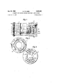
- Figure 1 is a diagrammatical axial section of a first embodiment of the apparatus
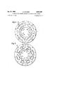
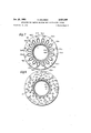
- FIGS 2 to 7 show the elements of the apparatus shown in Figure 1;
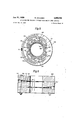
- Figure 8 shows an element of a further embodiment of the apparatus
- Figure 9 is a diagrammatic axial section thereof.
- Figure 10 is a diagrammatic axial section of a further embodiment
- Figure 11 shows a pipe provided with an extension for obtaining a thermoplastic two-layer section exceeding in diameter the diameter of the pipe lining.
- Figure 1 shows on the right in a conventional manner the successive conduits for delivering the two thermoplastic materials adapted to form the two layers of the lining, and on the left the mechanical connections for holding the head elements together.
- the material forming the inner layer of the lining enters the head of the apparatus through the supply opening A ( Figure 2) from an extrusion press, under a pressure such that the material reaches the annular slot R. From the connection A the material flows along the two circular conduits m1 and 102 ( Figure 2), reachingconduits 103 and 104 bored in the element 2 feeding the two circular conduits 105, 106 bored in the element 3 (Figstill ure- 3 -Atthe ends 'of 'the i'ast mentioned 'co'n'duit'sfour Patented Jan. 21, 1958 vertical conduits 107, 108, 109, 110 feed four circular conduits 111, 112, 113, 114 ( Figure 4).
- the supply conduits 147, 148 (thirty-two in number in all) leading to the annular slot R are arranged so as to afford a uniform delivery of the material throughout the length of the slot, the resistance opposing the flow of the material from the extrusion press to the conduits 147, 148 being the same throughout the conduits.
- the material issuing from the annular slot R in a direction normal to the inner surface forms a layer practically of uniform thickness on the pipe which is fed along the axis of the apparatus.
- Delivery of the second material forming the inner layer of the lining from the extrusion press to the annu lar slot T is effected as shown on the drawings in a manner similar to the delivery of the first material.
- the material fiows through the element 5 along the vertical bores 131a, Idfia- ( Figures 1 and 6) bored in'the'element 5, and through conduits 131b, 14Gb to the opening 147a, 148a feeding the annular slot T.
- a basic feature of the invention consists in the fact that the bore of the conduit into which the annular slots open is considerably larger than the outer diameter of the pipe 'to be coated, whereby articles having an uneven outer surface, more. particularly articles having an end socket can be successfully coated.
- the apparatus just described is maintained at the desired temperatures from the outside by heating means denoted in Figure l by 35, 36, 37.
- the heating means may consist of electric resistances or jackets for the circulation of liquid or steam at suitable temperature.
- apparatus has been described merely by way of example and apparatus can be designed in which the individual annular conduits are fed through a larger number of supply openings. In this manner, the thickness of the pipe lining may be kept uniform even as the pipe diameter increases. It is possible to increase the number of supply conduits to the annular slots by increasing the number of elements composing the apparatus.
- the apparatus may be adapted by obvious modifications for making linings comprising more than two layers.
- the pipe to be coated is fed along the axis of the apparatus by means not shown on the drawing. It is possible to vary the thickness of the lining simply by varying the rate of feed of the pipe along the axis. It is further possible to vary the ratio between the thickness of the two layers of the lining simply by varying the ratio between the delivery of the two presses extruding the different coating materials.
- the possibility of varying the rate of feed of the pipe along the axis is of considerable importance, inasmuch as it is then possible to deposit on the pipe portion of larger diameter a coating lay-er equalling in thickness the layer deposited on the remaining pipe portion. it is sufiicient for the purpose to conveniently reduce the rate of feed at the socket end.
- Figures 8 and 9 show an apparatus based on the principle of arranging the successive delivery conduits for the thermoplastic material in two opposite elements.
- I 201 which contains half the system of delivery conduits for the second material, to intermediate element 202 containing in its two opposed faces the other halves of the two systems of delivery conduits.
- the delivery conduits are provided with the same reference numerals as the corresponding delivery conduits of the machine shown in Figures 1 to 7.
- a quite obvious modification of this second embodiment of the machine consists in subdividing the intermediate element into two elements, one of which contains half the delivery network for the first thermoplastic material, while the other contains half the delivery network for the second thermoplastic material.
- FIG 10 is a diagrammatical axial sectional view of a third embodiment of the apparatus according to this invention.
- the apparatus comprises two superposed elements, in one of which the delivery of the first thermoplastic material is eliected in a quite similar manner as in the apparatus illustrated in Figures 1 to 7, while in apparatus then comprises but three elements, of which the top element 209 contains one half of the system of delivery conduits for the first material, to lower element is very strong against abrasion.
- the material adapted to form the outer protecting layer is delivered.
- the three embodiments of the apparatus according to this invention arebased on the same theoretical principle but solve in practice different problems.
- the first apparatus solves the problem of coating middle-sized pipes
- the second embodiment serves for coating small diameter pipes
- the third embodiment is more particularly suitable for coating large diameter pipes.
- coated articles of a special character can be obtained.
- the slot, through which the material forming the outer layer issues it will be sufficient to limit the slot, through which the material forming the outer layer issues, to a plurality of discontinuous sections conforming with the desired strips on the outside of the pipe.
- These strips can take helical shape by combining with the feed of the pipe along the apparatus axis a rotation of the pipe about its axis.
- the pitch of the helix depends in this case upon the ratio between the rate of feed of the pipe along the axis of the apparatus and the rotational speed of the pipe.
- the apparatus according to this invention permits of providing the ends of the coated pipe with a tubular section of two-layer thermoplastic material exceeding in diameter the pipe lining.
- a cylindrical disassemblable member M is fitted ( Figure 11) on the end of the pipe L, the member M being larger in diameter than the pipe.
- the section M is likewise coated with a two-layer lining. Since the member M is disassemblable, it can be easily removed from the two-layer lining, which is then cut along the connecting line between the two linings differing in diameter.
- the section of two-layer protecting tube of larger diameter is used for protecting joints between two pipe sections according to a special technique which is described in a copending application.
- a very advantageous combination for protecting pipes against wandering currents comprises an inner polyethylene layer and an outer layer of polyvinyl chloride.
- the polyethylene layer has a high insulating power, while the polyvinyl chloride layer
- Further advantageous combinations result from the use of a layer of high insulating power with an outer layer of nylon which is highly abrasion-resistant.
- the various elements of the machine are held together by means of bolts seated in holes 151 bored in the apparatus elements.
- the contact surface of the various component parts of the apparatus are shaped and machined to avoid escape of material under pressure between the machine elements.
- Apparatus for coating with plastic material articles comprising a plurality of discs each having a central bore, said discs being connected together with their central bores in axial alignment to define a tubular body, through the central bore of which the article to be coated can be advanced, a branched conduit system in said tubular body comprising axially spaced annular slots opening at the inner wall of said tubular body shaped to direct the synthetic material in a direction normal to the surface of the article to be coated, each of said slots being out between two contiguous discs, sets of arcuate conduits for supplying synthetic material to each of said slots, said conduits being defined by mating grooves in the contiguous faces of said discs and terminating in end bores for connecting the arcuate conduits between pairs of successive discs, and wherein said conduits in any horizontal plane forming a part of one said conduit system are approximately of equal length whereby a system of branching conduits is obtained through which the slots may be uniformly supplied with the plastic material.
- Apparatus for coating elongated articles such as pipes and tubes with a plastic material comprising a tubular body through which a tube may be advanced, said body defining a plurality of annular radially directed extrusion slots opening in axially spaced relationship on the inner tubular surface of the body, said body further defining an inlet opening for the material and a conduit system associated with each of the slots for supplying the material thereto, each said system comprising a set of pairs of conduits radially opening within the slot, a further peripheral set of pairs of conduits with the conduits of each pair branching to form each a pair of conduits of the said first named set, and at least one further set of conduits connecting the pairs of said second set to the said inlet opening, and wherein the conduits of any single set are of approximately the same length.
Description
1958 i R. COLOMBO 2,820,249
APPARATUS FOR COATING ARTICLES WITH MULTI-LAYER LININGS Filed 001;. e, 1953 I 5 Sheets-Shet 1 Fig. 7
Jan. 21, 1958- R. COLOMBO I 2,820,249
APPARATUS FOR COATING ARTICLES WITH MULTI-LAYER LININGS Filed 001. s,' 1ss e 5 Sheets-Sheet 2 Jan. 21, 1958 R. COLOMBO 2,820,249
APPARATUS FOR COATING ARTICLES WITH MULTI-LAYER LININGS Filed Oct. 6. 1952; 5 Shets-Sheet s Jan. 21, 1958 IR. COLOMBO 2,820,249
' APPARATUS FOR comma ARTICLES WITH MULTI-LAYER LININGS Filed 001;. 6,- 1953 5 Sheets-Sheet 4 KAT 1958 R. COLOMBO 2,820,249
APPARATUS FOR COATING ARTICLES WITH MULTI-LAYER LININGS Filed Oct. 6, 1953 5 Sheets-Sheet 5 Fig. 70
APPARATUS non conrnso ARTICLES Murrr-rarnnrnsmcs Roberto Colombo, Turin, Italy, assignor to S. A. S.
Lavorazione Mater-lie Plastiche (L. M. P.) di M. I Colombo d; S, Turin, Italy Application October 6, 1953,Serial No. 384,479
Claims priority, application Italy October 8, 1952 7 Claims. (Cl. 18-13) It is known that iron and steel articles, and more particularly tubes and pipes for conveying liquids or gas which are buried in the ground at various depths, are subject to corrosion for various reasons such as the effect of stray currents in the ground and electrolysis processes due to these currents. This corrosion leads to the perforating of the pipings through which liquids or gases conveyed thereby are dispersed.
The problem of protecting pipes embedded in the ground is at present of especially great interest in connection with ducts or pipe lines conveying natural gas, such as methane, inasmuch as, while pressure rates of coke gas in gas mains are very low, the gas pressure for methane and the like reaches considerable values.
Protection of pipes against stray currents Was taken care of heretofore by coating the pipes with linings made from tar layers or layers of tar admixed with jute and glass wool. Special paints have also been employed. The chief drawback of these types of protection resides in the fact that they can be injured during transport and laying on account of the low strength against wear and shock of the lining.
A further known protection against stray currents consists of laying the metal pipes in cement ducts further protected on the outside or inside by layers of materials opposing the access of stray currents. This method, which has heretofore afforded the best results, is very expensive.
The requirements which should be met by the protecting lining are chiefly as follows:
(1) High electric resistance;
(2) High strength against shock and wear in order to avoid injuries during transport and laying.
It has been rather difiicult in practice to find material's meeting both requirements.
It has further been attempted to solve the problem of coating pipes by employing synthetic resin linings. A decided improvement was reached by the winding around metallic pipes plates of vinyl resins and welding the plates along a pipe generatrix. Thepolyvinyl resin plates are unattached by acids and reduce the action of stray currents on the pipe. Moreover, they insulate the pipe from the ground preventing rusting thereof. Polyvinyl chloride sufiers, however, from the drawback of an insuflicient electric resistance, which is variable with moisture content.
The polyvinyl resin layer has been produced by direct winding about the pipe and welding of the abutting edges, or by extruding the thermoplastic material on the .pipe so as to uniformly deposit the material on the outer pipe surface.
The process according to this invention solves the prob lem of coating pipes by adopting a multilayer lining, each layer having special properties, so that the lining as a whole actually meets all requirements. The invention further provides an apparatus for coating the pipe by one step in a simple and inexpensive manner.
With the process according to this invention, each layer may be made of a material properly meeting a given requirement. For instance, a; layer of a material of high electric resistance may be combined with a layer of high mechanical strength, so as to obtain a unit which fully meets operating conditions. For instance, by coating an iron pipe with a layer of polyethylene resin, a lining results which is excellent from the standpoint of insulation, though it hardly resists abrasion, because the super: ficial hardness of polyethylene resin is limited. By superposing on this first layer a coating of polyvinyl resin worked Without the addition of plasticizers, an outer layer is obtained which for a very great strength against abrasion. The pipe protected by the two coating layers is fully satisfactory.
The two-layer lining makes up for any discontinuity in the layer in direct contact with the pipe. This safely avoids any access of moisture and stray currents to the pipe.
With the apparatus according to this invention a multilayer lining can be obtained on a metal article by one step. The lining on the article is of uniform thickness, even if the surface of the article is not smooth or even. The apparatus serves for coating pipes of uneven outer surface or pipes previously coated by a previous process and slightly corroded.
The process and apparatus according to this invention can be employed for the continuous coating of pipes of any diameter.
The basic principle of the process consists of extruding the thermoplastic material through a continuous slot fed from openings uniformly distributed over the periphery of the slot. The slot opens on a surface approximatelycoaxial with the surface of the article to be coated, which is fed along the axis of the surface, extrusion of the thermoplastic material being effected in a direction normal to the surface of the article to be coated. The distribution of the opening feeding the continuous annular slot is such as to produce a uniform lining. With this object in view, besides arranging the supply openings at the corners of a regular polygon, care is taken that the load loss occurring in flow of the material from the extrusion press to the individual supply openings is the same at all the openings, whereby the delivery of the openings is uniform throughout the same.
Figure 1 is a diagrammatical axial section of a first embodiment of the apparatus;
Figures 2 to 7 show the elements of the apparatus shown in Figure 1;
Figure 8 shows an element of a further embodiment of the apparatus;
Figure 9 is a diagrammatic axial section thereof;
Figure 10 is a diagrammatic axial section of a further embodiment;
Figure 11 shows a pipe provided with an extension for obtaining a thermoplastic two-layer section exceeding in diameter the diameter of the pipe lining.
Figure 1 shows on the right in a conventional manner the successive conduits for delivering the two thermoplastic materials adapted to form the two layers of the lining, and on the left the mechanical connections for holding the head elements together.
The material forming the inner layer of the lining enters the head of the apparatus through the supply opening A (Figure 2) from an extrusion press, under a pressure such that the material reaches the annular slot R. From the connection A the material flows along the two circular conduits m1 and 102 (Figure 2), reachingconduits 103 and 104 bored in the element 2 feeding the two circular conduits 105, 106 bored in the element 3 (Figstill ure- 3 -Atthe ends 'of 'the i'ast mentioned 'co'n'duit'sfour Patented Jan. 21, 1958 vertical conduits 107, 108, 109, 110 feed four circular conduits 111, 112, 113, 114 (Figure 4). These four conduits end by the eight vertical conduits 115, 116, 117, 118, 119, 120, 121, 122 bored in the element 4 and feed ing in turn eight circular conduits 123, 124, 125, 126, 127, 128, 129, 130. Each of these conduits feeds at both ends two vertical conduits, sixteen vertical conduits 131, 146 (Figure 5) in all each of which feeds in turn two distinct conduits 147, 148 (Figure 6) merging into each other at the annular slot cut in the inner surface of the apparatus. The supply conduits 147, 148 (thirty-two in number in all) leading to the annular slot R are arranged so as to afford a uniform delivery of the material throughout the length of the slot, the resistance opposing the flow of the material from the extrusion press to the conduits 147, 148 being the same throughout the conduits.
In this manner, the material issuing from the annular slot R in a direction normal to the inner surface forms a layer practically of uniform thickness on the pipe which is fed along the axis of the apparatus.
Delivery of the second material forming the inner layer of the lining from the extrusion press to the annu lar slot T is effected as shown on the drawings in a manner similar to the delivery of the first material. The material fiows through the element 5 along the vertical bores 131a, Idfia- (Figures 1 and 6) bored in'the'element 5, and through conduits 131b, 14Gb to the opening 147a, 148a feeding the annular slot T.
A basic feature of the invention consists in the fact that the bore of the conduit into which the annular slots open is considerably larger than the outer diameter of the pipe 'to be coated, whereby articles having an uneven outer surface, more. particularly articles having an end socket can be successfully coated.
The apparatus just described is maintained at the desired temperatures from the outside by heating means denoted in Figure l by 35, 36, 37. The heating means may consist of electric resistances or jackets for the circulation of liquid or steam at suitable temperature.
It will be understood that the apparatus has been described merely by way of example and apparatus can be designed in which the individual annular conduits are fed through a larger number of supply openings. In this manner, the thickness of the pipe lining may be kept uniform even as the pipe diameter increases. It is possible to increase the number of supply conduits to the annular slots by increasing the number of elements composing the apparatus.
The apparatus may be adapted by obvious modifications for making linings comprising more than two layers.
The pipe to be coated is fed along the axis of the apparatus by means not shown on the drawing. It is possible to vary the thickness of the lining simply by varying the rate of feed of the pipe along the axis. It is further possible to vary the ratio between the thickness of the two layers of the lining simply by varying the ratio between the delivery of the two presses extruding the different coating materials. When coating pipes with end sockets, the possibility of varying the rate of feed of the pipe along the axis is of considerable importance, inasmuch as it is then possible to deposit on the pipe portion of larger diameter a coating lay-er equalling in thickness the layer deposited on the remaining pipe portion. it is sufiicient for the purpose to conveniently reduce the rate of feed at the socket end.
I The apparatus for coating the pipe with two distinct protecting layers can be carried out other than just described.
Figures 8 and 9 show an apparatus based on the principle of arranging the successive delivery conduits for the thermoplastic material in two opposite elements. The
I 201 which contains half the system of delivery conduits for the second material, to intermediate element 202 containing in its two opposed faces the other halves of the two systems of delivery conduits. In the figures, the delivery conduits are provided with the same reference numerals as the corresponding delivery conduits of the machine shown in Figures 1 to 7.
A quite obvious modification of this second embodiment of the machine consists in subdividing the intermediate element into two elements, one of which contains half the delivery network for the first thermoplastic material, while the other contains half the delivery network for the second thermoplastic material.
Figure 10 is a diagrammatical axial sectional view of a third embodiment of the apparatus according to this invention. The apparatus comprises two superposed elements, in one of which the delivery of the first thermoplastic material is eliected in a quite similar manner as in the apparatus illustrated in Figures 1 to 7, while in apparatus then comprises but three elements, of which the top element 209 contains one half of the system of delivery conduits for the first material, to lower element is very strong against abrasion.
the second half of the apparatus the material adapted to form the outer protecting layer is delivered.
The three embodiments of the apparatus according to this invention arebased on the same theoretical principle but solve in practice different problems. The first apparatus solves the problem of coating middle-sized pipes, the second embodiment serves for coating small diameter pipes, and the third embodiment is more particularly suitable for coating large diameter pipes.
By making obvious modifications to the apparatus described above, coated articles of a special character can be obtained. When an article having a striped outer lining is desired, it will be sufficient to limit the slot, through which the material forming the outer layer issues, to a plurality of discontinuous sections conforming with the desired strips on the outside of the pipe. These strips can take helical shape by combining with the feed of the pipe along the apparatus axis a rotation of the pipe about its axis. The pitch of the helix depends in this case upon the ratio between the rate of feed of the pipe along the axis of the apparatus and the rotational speed of the pipe.
The apparatus according to this invention, the bore of which exceeds the outer diameter of the coated pipe, permits of providing the ends of the coated pipe with a tubular section of two-layer thermoplastic material exceeding in diameter the pipe lining. With this object in view, a cylindrical disassemblable member M is fitted (Figure 11) on the end of the pipe L, the member M being larger in diameter than the pipe. By feeding the pipe the axis of the machine, the section M is likewise coated with a two-layer lining. Since the member M is disassemblable, it can be easily removed from the two-layer lining, which is then cut along the connecting line between the two linings differing in diameter. The section of two-layer protecting tube of larger diameter is used for protecting joints between two pipe sections according to a special technique which is described in a copending application.
The materials used for coating the pipe can be of widely different types. A very advantageous combination for protecting pipes against wandering currents comprises an inner polyethylene layer and an outer layer of polyvinyl chloride. The polyethylene layer has a high insulating power, while the polyvinyl chloride layer Further advantageous combinations result from the use of a layer of high insulating power with an outer layer of nylon which is highly abrasion-resistant.
In the field of pipes with a three-layer lining, highly satisfactory results have been obtained by an inner tar layer, an intermediate polyethylene layer and an outer polyvinyl chloride layer.
The various elements of the machine are held together by means of bolts seated in holes 151 bored in the apparatus elements. The contact surface of the various component parts of the apparatus are shaped and machined to avoid escape of material under pressure between the machine elements.
What I claim is:
1. Apparatus for coating with plastic material articles, more particularly tubes and pipes, comprising a plurality of discs each having a central bore, said discs being connected together with their central bores in axial alignment to define a tubular body, through the central bore of which the article to be coated can be advanced, a branched conduit system in said tubular body comprising axially spaced annular slots opening at the inner wall of said tubular body shaped to direct the synthetic material in a direction normal to the surface of the article to be coated, each of said slots being out between two contiguous discs, sets of arcuate conduits for supplying synthetic material to each of said slots, said conduits being defined by mating grooves in the contiguous faces of said discs and terminating in end bores for connecting the arcuate conduits between pairs of successive discs, and wherein said conduits in any horizontal plane forming a part of one said conduit system are approximately of equal length whereby a system of branching conduits is obtained through which the slots may be uniformly supplied with the plastic material.
2. Apparatus as claimed in claim 1, in which the cen tral bore in the tubular body is cylindrical and is appreciably larger in diameter than the tube to be coated, so as to permit of coating variable diameter tubes.
3. Apparatus as claimed in claim 1, in which the arcuate conduits and the connecting bores for said conduits are arranged with their axes situated on co-axial cylindrical surfaces.
4. Apparatus as claimed in claim 1, in which the arcuate conduits and connecting bores for said conduits are arranged on parallel cross planes extending through the extrusion slots.
5. Apparatus as claimed in claim 1, in which the arcuate conduits in any one horizontal plane and the connecting bores for the latter said conduits are arranged with their axes on the same cylindrical surface.
6. Apparatus for coating elongated articles such as pipes and tubes with a plastic material comprising a tubular body through which a tube may be advanced, said body defining a plurality of annular radially directed extrusion slots opening in axially spaced relationship on the inner tubular surface of the body, said body further defining an inlet opening for the material and a conduit system associated with each of the slots for supplying the material thereto, each said system comprising a set of pairs of conduits radially opening within the slot, a further peripheral set of pairs of conduits with the conduits of each pair branching to form each a pair of conduits of the said first named set, and at least one further set of conduits connecting the pairs of said second set to the said inlet opening, and wherein the conduits of any single set are of approximately the same length.
7. Apparatus as claimed in claim 6, wherein the inner diameter of the tubular body is substantially larger than the diameter of the article.
References Cited in the file of this patent UNITED STATES PATENTS 876,755 Webb Ian. 14, 1908 1,859,901 Trebes May 24, 1932 2,154,333 Kampfer Apr. 11, 1939 2,175,125 Mack et al. Oct. 3, 1939 2,340,326 Horrigan Feb. 1, 1944 2,447,420 Moore Aug. 17, 1948 2,501,690 Prendergast Mar. 28, 1950 2,563,397 Colombo Aug. 7, 1951 2,607,712 Sturken Aug. 19, 1952 2,646,822 Ferguson July 28, 1953 2,688,767 Gray et al. Sept. 14, 1954 2,730,762 Ballard Jan. 17, 1956 2,734,224 Winstead Feb. 14, 1956 FOREIGN PATENTS 613,635 Great Britain Dec. 1, 1948
Applications Claiming Priority (1)
| Application Number | Priority Date | Filing Date | Title |
|---|---|---|---|
| IT2820249X | 1952-10-08 |
Publications (1)
| Publication Number | Publication Date |
|---|---|
| US2820249A true US2820249A (en) | 1958-01-21 |
Family
ID=11436033
Family Applications (1)
| Application Number | Title | Priority Date | Filing Date |
|---|---|---|---|
| US384479A Expired - Lifetime US2820249A (en) | 1952-10-08 | 1953-10-06 | Apparatus for coating articles with multi-layer linings |
Country Status (2)
| Country | Link |
|---|---|
| US (1) | US2820249A (en) |
| CH (1) | CH315684A (en) |
Cited By (44)
| Publication number | Priority date | Publication date | Assignee | Title |
|---|---|---|---|---|
| US3038201A (en) * | 1955-12-21 | 1962-06-12 | Multiple Extrusions Inc | Multiple tube extrusion apparatus and method |
| US3308503A (en) * | 1963-03-22 | 1967-03-14 | Textile & Chemical Res Company | Mixing device for spinnerettes |
| US3308508A (en) * | 1964-10-02 | 1967-03-14 | Dow Chemical Co | Die |
| US3315306A (en) * | 1965-10-15 | 1967-04-25 | Dow Chemical Co | Apparatus for the production of multilayer film |
| US3320636A (en) * | 1965-09-20 | 1967-05-23 | Nat Distillers Chem Corp | Multi-ply flow diverter for thermoplastic materials |
| US3327349A (en) * | 1965-08-30 | 1967-06-27 | Dow Chemical Co | Extrusion adaptor |
| US3334382A (en) * | 1965-08-30 | 1967-08-08 | Dow Chemical Co | Extrusion adapter |
| US3337914A (en) * | 1966-01-03 | 1967-08-29 | Nat Distillers Chem Corp | Stacked extrusion die |
| US3343215A (en) * | 1965-04-23 | 1967-09-26 | Barmag Barmer Maschf | Deflecting extruder head |
| US3355765A (en) * | 1965-09-02 | 1967-12-05 | Borg Warner | Pelletizing machine |
| US3418687A (en) * | 1966-10-24 | 1968-12-31 | Du Pont | Extruding apparatus |
| DE2939399A1 (en) * | 1978-10-10 | 1980-04-30 | Kendall & Co | METHOD FOR COATING TUBES AND TUBES OBTAINED THEREOF |
| EP0024220A1 (en) * | 1979-08-21 | 1981-02-25 | Ollivier, Jean | Process for manufacturing a tube composed of a metal and plastics material, and apparatus for carrying out this process |
| US4370186A (en) * | 1980-12-19 | 1983-01-25 | Nadia Nicoll, Societe A Responsabilite Limitee | Method for manufacturing a metal-plastics composite tube and apparatus for carrying out said method |
| US4403934A (en) * | 1980-02-29 | 1983-09-13 | Ole-Bendt Rasmussen | Coextrusion die |
| EP0091235A2 (en) * | 1982-04-03 | 1983-10-12 | Polyolefine Fibres & Engineering Company Limited | Improvements in or relating to die heads for extruding plastics materials |
| FR2625941A1 (en) * | 1988-01-14 | 1989-07-21 | Mcneil Akron Repiquet Sarl | Head for continuous extrusion or coextrusion with multiple annular orifices |
| US4871413A (en) * | 1985-02-21 | 1989-10-03 | Ashinori Industry Co., Ltd. | Apparatus for manufacturing tubular lining material |
| WO1990011880A1 (en) * | 1989-04-01 | 1990-10-18 | Erich Beck | An extrusion tool to shape viscous compounds |
| EP0419983A1 (en) * | 1989-09-26 | 1991-04-03 | Haka Ag Fabrik Für Kunststoffprodukte | Extrusion head for multi-layered extrudates |
| FR2674180A1 (en) * | 1991-03-22 | 1992-09-25 | Reifenhaeuser Masch | DIE HEAD FOR THE EXTRUSION OF PREFORMS IN THE FORM OF FLEXIBLE PIPES OR TUBES OF THERMOPLASTIFIED MATERIAL. |
| EP0542272A1 (en) * | 1991-11-14 | 1993-05-19 | CROMPTON & KNOWLES CORPORATION | Spiral fed multi-layer tubular die |
| WO1994008774A1 (en) * | 1992-10-17 | 1994-04-28 | Krupp Bellaform Maschinenbau Gmbh | Process and spray head for producing and/or coating extruded sections |
| WO1996033856A1 (en) * | 1995-04-24 | 1996-10-31 | Black Clawson Sano Inc. | Extrusion die |
| US5672303A (en) * | 1992-10-17 | 1997-09-30 | Bellaform Extrusionstechnik Gmbh | Process and extruding head for the manufacture and/or coating of extruding profiles |
| WO1998017459A1 (en) * | 1996-10-22 | 1998-04-30 | Schirmer Henry G | Modular disk coextrusion die |
| US6000926A (en) * | 1996-10-22 | 1999-12-14 | Schirmer; Henry G. | Modular disk coextrusion die |
| US6660086B1 (en) | 2000-03-06 | 2003-12-09 | Innovative Coatings, Inc. | Method and apparatus for extruding a coating upon a substrate surface |
| US20050266109A1 (en) * | 2003-01-27 | 2005-12-01 | Scimed Life Systems, Inc., A Delaware Corporation | Multilayer balloon catheter |
| US20070020475A1 (en) * | 2005-07-21 | 2007-01-25 | Prince Kendall W | Primed substrate and method for making the same |
| EP1916087A1 (en) | 2006-10-26 | 2008-04-30 | Drossbach GmbH & Co. KG | Device for applying plastic to a workpiece |
| WO2013082061A1 (en) * | 2011-11-29 | 2013-06-06 | Corning Incorporated | Apparatus and method for skinning articles |
| CN103348418A (en) * | 2011-02-10 | 2013-10-09 | 株式会社自动网络技术研究所 | Wire harness, method for producing wire harness, and apparatus for producing wire harness |
| US8870561B2 (en) | 2012-03-16 | 2014-10-28 | Bbs Corporation | Layer sequence repeater module for a modular disk co-extrusion die and products thereof |
| US20150105896A1 (en) * | 2011-11-29 | 2015-04-16 | Corning Incorporated | Process for axial skinning apparatus |
| US9289795B2 (en) | 2008-07-01 | 2016-03-22 | Precision Coating Innovations, Llc | Pressurization coating systems, methods, and apparatuses |
| US9616457B2 (en) | 2012-04-30 | 2017-04-11 | Innovative Coatings, Inc. | Pressurization coating systems, methods, and apparatuses |
| US10611051B2 (en) | 2013-10-15 | 2020-04-07 | Corning Incorporated | Systems and methods for skinning articles |
| US10744675B2 (en) | 2014-03-18 | 2020-08-18 | Corning Incorporated | Skinning of ceramic honeycomb bodies |
| US11090853B2 (en) | 2019-06-14 | 2021-08-17 | Bbs Corporation | Modular disk coextrusion die with opposing disk arrangement |
| US11173642B1 (en) | 2021-04-09 | 2021-11-16 | Bbs Corporation | Blown film coextrusion line with polygonal extruder arrangement |
| US11220035B2 (en) | 2019-06-14 | 2022-01-11 | Henry G. Schirmer | Complex films made from modular disk coextrusion die with opposing disk arrangement |
| US11338490B1 (en) | 2021-04-09 | 2022-05-24 | Bbs Corporation | Blown film coextrusion line with polygonal extruder arrangement |
| US11511474B1 (en) | 2021-05-17 | 2022-11-29 | Henry G. Schirmer | Modular disk coextrusion die with melt channeling disk |
Families Citing this family (2)
| Publication number | Priority date | Publication date | Assignee | Title |
|---|---|---|---|---|
| DE1246337B (en) * | 1960-10-05 | 1967-08-03 | G S T Ges Fuer Selbsttaetige T | Block-shaped pressure medium line system made of rigid and elastic plates |
| DE1650066B1 (en) * | 1967-10-24 | 1971-09-09 | Edmund Kutscher | LINKAGE SYSTEM FOR HYDRAULIC OR PNEUMATIC CIRCUITS |
Citations (14)
| Publication number | Priority date | Publication date | Assignee | Title |
|---|---|---|---|---|
| US876755A (en) * | 1907-03-26 | 1908-01-14 | Arthur H Hyde | Wire-coating machine. |
| US1859901A (en) * | 1929-09-11 | 1932-05-24 | Bell Telephone Labor Inc | Extruding apparatus |
| US2154333A (en) * | 1936-04-23 | 1939-04-11 | Kampfer Adolf | Process for extruding plastic masses onto sheets |
| US2175125A (en) * | 1937-06-15 | 1939-10-03 | Reynolds Res Corp | Method for forming films and film coatings |
| US2340326A (en) * | 1942-05-18 | 1944-02-01 | Lewis Perrault | Apparatus for covering pipe |
| US2447420A (en) * | 1945-09-29 | 1948-08-17 | Moore & Co Samuel | Plastic coated article |
| GB613635A (en) * | 1945-06-23 | 1948-12-01 | Jean Delorme | Improvements in the production of articles from multi-coloured plastic materials by extrusion |
| US2501690A (en) * | 1947-12-09 | 1950-03-28 | Carter Products Corp | Method and apparatus for making multiple layer plastic conduits |
| US2563397A (en) * | 1951-08-07 | Apparatus foe manufacturing tubes | ||
| US2607712A (en) * | 1952-01-28 | 1952-08-19 | Frank W Egan & Company | Extrusion coating machine |
| US2646822A (en) * | 1949-12-31 | 1953-07-28 | Presstite Engineering Company | Plastic-coated pipe and pipe fitting |
| US2688767A (en) * | 1950-12-06 | 1954-09-14 | Western Electric Co | Apparatus for continuously making vulcanized articles |
| US2730762A (en) * | 1953-04-21 | 1956-01-17 | American Viscose Corp | Apparatus for the continuous fabrication of reinforced tubing |
| US2734224A (en) * | 1956-02-14 | winstead |
-
1953
- 1953-10-01 CH CH315684D patent/CH315684A/en unknown
- 1953-10-06 US US384479A patent/US2820249A/en not_active Expired - Lifetime
Patent Citations (14)
| Publication number | Priority date | Publication date | Assignee | Title |
|---|---|---|---|---|
| US2563397A (en) * | 1951-08-07 | Apparatus foe manufacturing tubes | ||
| US2734224A (en) * | 1956-02-14 | winstead | ||
| US876755A (en) * | 1907-03-26 | 1908-01-14 | Arthur H Hyde | Wire-coating machine. |
| US1859901A (en) * | 1929-09-11 | 1932-05-24 | Bell Telephone Labor Inc | Extruding apparatus |
| US2154333A (en) * | 1936-04-23 | 1939-04-11 | Kampfer Adolf | Process for extruding plastic masses onto sheets |
| US2175125A (en) * | 1937-06-15 | 1939-10-03 | Reynolds Res Corp | Method for forming films and film coatings |
| US2340326A (en) * | 1942-05-18 | 1944-02-01 | Lewis Perrault | Apparatus for covering pipe |
| GB613635A (en) * | 1945-06-23 | 1948-12-01 | Jean Delorme | Improvements in the production of articles from multi-coloured plastic materials by extrusion |
| US2447420A (en) * | 1945-09-29 | 1948-08-17 | Moore & Co Samuel | Plastic coated article |
| US2501690A (en) * | 1947-12-09 | 1950-03-28 | Carter Products Corp | Method and apparatus for making multiple layer plastic conduits |
| US2646822A (en) * | 1949-12-31 | 1953-07-28 | Presstite Engineering Company | Plastic-coated pipe and pipe fitting |
| US2688767A (en) * | 1950-12-06 | 1954-09-14 | Western Electric Co | Apparatus for continuously making vulcanized articles |
| US2607712A (en) * | 1952-01-28 | 1952-08-19 | Frank W Egan & Company | Extrusion coating machine |
| US2730762A (en) * | 1953-04-21 | 1956-01-17 | American Viscose Corp | Apparatus for the continuous fabrication of reinforced tubing |
Cited By (72)
| Publication number | Priority date | Publication date | Assignee | Title |
|---|---|---|---|---|
| US3038201A (en) * | 1955-12-21 | 1962-06-12 | Multiple Extrusions Inc | Multiple tube extrusion apparatus and method |
| US3308503A (en) * | 1963-03-22 | 1967-03-14 | Textile & Chemical Res Company | Mixing device for spinnerettes |
| US3308508A (en) * | 1964-10-02 | 1967-03-14 | Dow Chemical Co | Die |
| US3343215A (en) * | 1965-04-23 | 1967-09-26 | Barmag Barmer Maschf | Deflecting extruder head |
| US3334382A (en) * | 1965-08-30 | 1967-08-08 | Dow Chemical Co | Extrusion adapter |
| US3327349A (en) * | 1965-08-30 | 1967-06-27 | Dow Chemical Co | Extrusion adaptor |
| US3355765A (en) * | 1965-09-02 | 1967-12-05 | Borg Warner | Pelletizing machine |
| US3320636A (en) * | 1965-09-20 | 1967-05-23 | Nat Distillers Chem Corp | Multi-ply flow diverter for thermoplastic materials |
| US3315306A (en) * | 1965-10-15 | 1967-04-25 | Dow Chemical Co | Apparatus for the production of multilayer film |
| US3337914A (en) * | 1966-01-03 | 1967-08-29 | Nat Distillers Chem Corp | Stacked extrusion die |
| US3418687A (en) * | 1966-10-24 | 1968-12-31 | Du Pont | Extruding apparatus |
| DE2939399A1 (en) * | 1978-10-10 | 1980-04-30 | Kendall & Co | METHOD FOR COATING TUBES AND TUBES OBTAINED THEREOF |
| US4211595A (en) * | 1978-10-10 | 1980-07-08 | The Kendall Company | Method of coating pipe |
| EP0024220A1 (en) * | 1979-08-21 | 1981-02-25 | Ollivier, Jean | Process for manufacturing a tube composed of a metal and plastics material, and apparatus for carrying out this process |
| FR2463673A1 (en) * | 1979-08-21 | 1981-02-27 | Ollivier Jean | PROCESS FOR MANUFACTURING A METAL-PLASTIC COMPOSITE TUBE AND APPARATUS FOR IMPLEMENTING IT |
| EP0092188A2 (en) * | 1980-02-29 | 1983-10-26 | RASMUSSEN, Ole-Bendt | Coextrusion die |
| US4403934A (en) * | 1980-02-29 | 1983-09-13 | Ole-Bendt Rasmussen | Coextrusion die |
| US4492549A (en) * | 1980-02-29 | 1985-01-08 | Ole-Bendt Rasmussen Rasmussen | Coextrusion die |
| EP0092188A3 (en) * | 1980-02-29 | 1985-10-02 | Ole-Bendt Rasmussen | Coextrusion die |
| US4370186A (en) * | 1980-12-19 | 1983-01-25 | Nadia Nicoll, Societe A Responsabilite Limitee | Method for manufacturing a metal-plastics composite tube and apparatus for carrying out said method |
| EP0091235A2 (en) * | 1982-04-03 | 1983-10-12 | Polyolefine Fibres & Engineering Company Limited | Improvements in or relating to die heads for extruding plastics materials |
| EP0091235A3 (en) * | 1982-04-03 | 1984-10-17 | Polyolefine Fibres & Engineering Company Limited | Improvements in or relating to die heads for extruding plastics materials |
| US4871413A (en) * | 1985-02-21 | 1989-10-03 | Ashinori Industry Co., Ltd. | Apparatus for manufacturing tubular lining material |
| FR2625941A1 (en) * | 1988-01-14 | 1989-07-21 | Mcneil Akron Repiquet Sarl | Head for continuous extrusion or coextrusion with multiple annular orifices |
| JPH03501712A (en) * | 1989-04-01 | 1991-04-18 | ベツク,エリツヒ | Injection molding equipment for semi-fluid materials |
| WO1990011880A1 (en) * | 1989-04-01 | 1990-10-18 | Erich Beck | An extrusion tool to shape viscous compounds |
| EP0419983A1 (en) * | 1989-09-26 | 1991-04-03 | Haka Ag Fabrik Für Kunststoffprodukte | Extrusion head for multi-layered extrudates |
| FR2674180A1 (en) * | 1991-03-22 | 1992-09-25 | Reifenhaeuser Masch | DIE HEAD FOR THE EXTRUSION OF PREFORMS IN THE FORM OF FLEXIBLE PIPES OR TUBES OF THERMOPLASTIFIED MATERIAL. |
| US5208048A (en) * | 1991-03-22 | 1993-05-04 | Reifenhauser Gmbh & Co. Maschinenfabrik | Extrusion head for tubular strands of thermoplastified synthetic resin material |
| EP0542272A1 (en) * | 1991-11-14 | 1993-05-19 | CROMPTON & KNOWLES CORPORATION | Spiral fed multi-layer tubular die |
| WO1994008774A1 (en) * | 1992-10-17 | 1994-04-28 | Krupp Bellaform Maschinenbau Gmbh | Process and spray head for producing and/or coating extruded sections |
| US5672303A (en) * | 1992-10-17 | 1997-09-30 | Bellaform Extrusionstechnik Gmbh | Process and extruding head for the manufacture and/or coating of extruding profiles |
| WO1996033856A1 (en) * | 1995-04-24 | 1996-10-31 | Black Clawson Sano Inc. | Extrusion die |
| US5716650A (en) * | 1995-04-24 | 1998-02-10 | Black Clawson Sano Inc. | Multilayer modular extrusion die |
| WO1998017459A1 (en) * | 1996-10-22 | 1998-04-30 | Schirmer Henry G | Modular disk coextrusion die |
| US6000926A (en) * | 1996-10-22 | 1999-12-14 | Schirmer; Henry G. | Modular disk coextrusion die |
| US6660086B1 (en) | 2000-03-06 | 2003-12-09 | Innovative Coatings, Inc. | Method and apparatus for extruding a coating upon a substrate surface |
| US20040109946A1 (en) * | 2000-03-06 | 2004-06-10 | Prince Kendall W. | Method and apparatus for extruding a coating upon a substrate surface |
| US7374795B2 (en) | 2000-03-06 | 2008-05-20 | Innovative Coatings Inc. | Method for extruding a coating upon a substrate surface |
| US20080314312A1 (en) * | 2000-03-06 | 2008-12-25 | Prince Kendall W | Method and apparatus for extruding a coating upon a substrate surface |
| US8113143B2 (en) | 2000-03-06 | 2012-02-14 | Prince Kendall W | Method and apparatus for extruding a coating upon a substrate surface |
| US20050266109A1 (en) * | 2003-01-27 | 2005-12-01 | Scimed Life Systems, Inc., A Delaware Corporation | Multilayer balloon catheter |
| US20080145469A1 (en) * | 2003-01-27 | 2008-06-19 | Boston Scientific Scimed, Inc. | Extrusion apparatus for making multilayer articles |
| US7713047B2 (en) | 2003-01-27 | 2010-05-11 | Boston Scientific Scimed, Inc. | Extrusion apparatus for making multilayer articles |
| US20070020475A1 (en) * | 2005-07-21 | 2007-01-25 | Prince Kendall W | Primed substrate and method for making the same |
| EP1916087A1 (en) | 2006-10-26 | 2008-04-30 | Drossbach GmbH & Co. KG | Device for applying plastic to a workpiece |
| US20080127890A1 (en) * | 2006-10-26 | 2008-06-05 | Johann Karl | Device for applying plastic to a workpiece |
| US10576491B2 (en) | 2008-07-01 | 2020-03-03 | Precision Coating Innovations, Llc | Pressurization coating systems, methods, and apparatuses |
| US9289795B2 (en) | 2008-07-01 | 2016-03-22 | Precision Coating Innovations, Llc | Pressurization coating systems, methods, and apparatuses |
| US20140290572A1 (en) * | 2011-02-10 | 2014-10-02 | Autonetwork Technologies, Ltd. | Wire harness, wire harness manufacturing method and wire harness manufacturing apparatus |
| CN103348418A (en) * | 2011-02-10 | 2013-10-09 | 株式会社自动网络技术研究所 | Wire harness, method for producing wire harness, and apparatus for producing wire harness |
| US9653197B2 (en) | 2011-02-10 | 2017-05-16 | Autonetwork Technologies, Ltd. | Wire harness, wire harness manufacturing method and wire harness manufacturing apparatus |
| US9613732B2 (en) | 2011-02-10 | 2017-04-04 | Autonetworks Technologies, Ltd. | Wire harness, wire harness manufacturing method and wire harness manufacturing apparatus |
| US9378871B2 (en) * | 2011-02-10 | 2016-06-28 | Autonetworks Technologies, Ltd. | Wire harness, wire harness manufacturing method and wire harness manufacturing apparatus |
| US9803523B2 (en) * | 2011-11-29 | 2017-10-31 | Corning Incorporated | Process for axial skinning apparatus |
| WO2013082061A1 (en) * | 2011-11-29 | 2013-06-06 | Corning Incorporated | Apparatus and method for skinning articles |
| US20150105896A1 (en) * | 2011-11-29 | 2015-04-16 | Corning Incorporated | Process for axial skinning apparatus |
| US10634025B2 (en) | 2011-11-29 | 2020-04-28 | Corning Incorporated | Apparatus and method for skinning articles |
| CN104220178A (en) * | 2011-11-29 | 2014-12-17 | 康宁股份有限公司 | Apparatus and method for skinning articles |
| US9670809B2 (en) | 2011-11-29 | 2017-06-06 | Corning Incorporated | Apparatus and method for skinning articles |
| US9132578B2 (en) | 2011-11-29 | 2015-09-15 | Corning Incorporated | Apparatus and method for skinning articles |
| US10611129B2 (en) | 2012-03-16 | 2020-04-07 | Renolit Nederland BV | Method for making multilayer coextruded films using a layer sequence repeater module |
| US8870561B2 (en) | 2012-03-16 | 2014-10-28 | Bbs Corporation | Layer sequence repeater module for a modular disk co-extrusion die and products thereof |
| US9616457B2 (en) | 2012-04-30 | 2017-04-11 | Innovative Coatings, Inc. | Pressurization coating systems, methods, and apparatuses |
| US10611051B2 (en) | 2013-10-15 | 2020-04-07 | Corning Incorporated | Systems and methods for skinning articles |
| US10744675B2 (en) | 2014-03-18 | 2020-08-18 | Corning Incorporated | Skinning of ceramic honeycomb bodies |
| US11090853B2 (en) | 2019-06-14 | 2021-08-17 | Bbs Corporation | Modular disk coextrusion die with opposing disk arrangement |
| US11220035B2 (en) | 2019-06-14 | 2022-01-11 | Henry G. Schirmer | Complex films made from modular disk coextrusion die with opposing disk arrangement |
| US11173642B1 (en) | 2021-04-09 | 2021-11-16 | Bbs Corporation | Blown film coextrusion line with polygonal extruder arrangement |
| US11338490B1 (en) | 2021-04-09 | 2022-05-24 | Bbs Corporation | Blown film coextrusion line with polygonal extruder arrangement |
| US11440233B1 (en) | 2021-04-09 | 2022-09-13 | Bbs Corporation | Blown film coextrusion line with polygonal extruder arrangement |
| US11511474B1 (en) | 2021-05-17 | 2022-11-29 | Henry G. Schirmer | Modular disk coextrusion die with melt channeling disk |
Also Published As
| Publication number | Publication date |
|---|---|
| CH315684A (en) | 1956-08-31 |
Similar Documents
| Publication | Publication Date | Title |
|---|---|---|
| US2820249A (en) | Apparatus for coating articles with multi-layer linings | |
| CN105221859B (en) | Fiber-reinforced thermal-insulation thermoplastic composite pipe and preparation method thereof | |
| US3335758A (en) | Plastic-lined conduit | |
| AU2012373352B2 (en) | Metal-containing polymeric reinforced pipe, method for manufacturing same and pipeline produced using said pipe | |
| EP0142482B1 (en) | Method and apparatus for continuously extruding single-wall ribbed conduits of plastics or other mouldable material | |
| EP0017501A1 (en) | A method of and apparatus for extruding plastics products | |
| US3483896A (en) | Composite reinforced plastic pipe | |
| US2632205A (en) | Method and apparatus for making lined tubing | |
| US3281897A (en) | Extruded plastic tubing | |
| JPH09225059A (en) | Fluid conduit system and its manufacture | |
| US4783299A (en) | Method and apparatus for extrusion of plastic pipes with composite walls | |
| KR100482387B1 (en) | Multi-layered fluid conduit and its manufacturing method | |
| EP0123917B1 (en) | Method and apparatus for extruding thermosetting resins | |
| WO1992003275A1 (en) | Coextrusion method and apparatus | |
| US2353951A (en) | Method of applying surface finish to pipe | |
| CA1158535A (en) | Method for making helically wound surface-coating tubes, and apparatus for carrying out this method | |
| US1933212A (en) | Tubing machine | |
| US2941915A (en) | Method of making reinforced composite pipe | |
| US3734662A (en) | Flat film plastic extrusion apparatus | |
| US3242528A (en) | Fluid beds and heating or cooling articles thereby | |
| CN114193805B (en) | Forming equipment of continuous fiber reinforced composite pipe | |
| DK156886B (en) | An extruder | |
| GB2242645A (en) | Controlling extrusion pressure around an annular nozzle of a multilayer parison extrusion die | |
| CN1221086A (en) | Structure and making method for compound reinforced tube waved by super high molecular weight polythene | |
| CN204493923U (en) | A kind of nonmetal continuous companion's thermal recovery oil composite pipe |