US2662687A - Centrifugal separator for cold milk products and the like - Google Patents
Centrifugal separator for cold milk products and the like Download PDFInfo
- Publication number
- US2662687A US2662687A US153408A US15340850A US2662687A US 2662687 A US2662687 A US 2662687A US 153408 A US153408 A US 153408A US 15340850 A US15340850 A US 15340850A US 2662687 A US2662687 A US 2662687A
- Authority
- US
- United States
- Prior art keywords
- bowl
- discs
- feed
- cream
- free space
- Prior art date
- Legal status (The legal status is an assumption and is not a legal conclusion. Google has not performed a legal analysis and makes no representation as to the accuracy of the status listed.)
- Expired - Lifetime
Links
Images

Classifications
-
- B—PERFORMING OPERATIONS; TRANSPORTING
- B04—CENTRIFUGAL APPARATUS OR MACHINES FOR CARRYING-OUT PHYSICAL OR CHEMICAL PROCESSES
- B04B—CENTRIFUGES
- B04B1/00—Centrifuges with rotary bowls provided with solid jackets for separating predominantly liquid mixtures with or without solid particles
- B04B1/04—Centrifuges with rotary bowls provided with solid jackets for separating predominantly liquid mixtures with or without solid particles with inserted separating walls
- B04B1/08—Centrifuges with rotary bowls provided with solid jackets for separating predominantly liquid mixtures with or without solid particles with inserted separating walls of conical shape
-
- B—PERFORMING OPERATIONS; TRANSPORTING
- B04—CENTRIFUGAL APPARATUS OR MACHINES FOR CARRYING-OUT PHYSICAL OR CHEMICAL PROCESSES
- B04B—CENTRIFUGES
- B04B11/00—Feeding, charging, or discharging bowls
- B04B11/06—Arrangement of distributors or collectors in centrifuges
Definitions
- This invention relates to centrifuges for separating liquids according to their relative specific gravities, and it has for its principal object the provision of an improved centrifuge adapted especially for the continuous separation of cream from whole milk at low temperature.
- the whole milk can be separated continuously at a temperature within the range of 40 F. to 50 and the inherent tendency of the highly viscous separated cream component to clog the bow overcome or, at least, greatly reduced.
- A. centrifuge made according to the invention comprises a stack of conical discs located in the separating chamber of a rotatable centrifugal bowl and forming thin separating spaces between the discs.
- the discs have central holes, and the bowl chamber has within the edges of these holes a free space which provides unobstructed C0i'llmunicaticn inwardly from the discs toward the rotation axi of the bowl.
- means are provided outside this free space which engage the discs and term a driving connection between the bowl and the discs.
- the milk product is fed to the separating chamber through an axial feed pipe having an air-tight connection with the bowl, the milk product being delivered from the feed pipe through a feed passage leading to the disc stack at a region spaced outwardly from the free space within the discs.
- the separated light component or cream is displaced inwardly from the discs into the free space, where it passes without obstruction into a central outlet passage leading from one end of this free space.
- the skim milk or heavy component separated between the discs passes to the outer part of the bowl and then into a second outlet passage.
- a stationary discharge pipe outside the bowl cornmunicates with the central or cream outlet passage, and an air-tight seal is provided between the discharge pipe and the bowl to form a closed path from the free space within the discs through the central outlet passage to the discharge pipe.
- the skim milk outlet passage also communicates through an air-tight seal with a second stationary discharge pipe outside the bowl.
- the separated cream can be discharged from the bowl under pressure without clogging it, even when the separated cream component is at relatively low temperature and has a high viscosity.
- the sealed connections with the bowl for the feed and the discharge enable the use of a relatively high pressure at the inlet side of the bowl, and because of the absence of the usual tubular shaft, disc support, or other obstruction at the inner edges of the discs, the relatively high pressure feed of the milk product is made eifective to force the separated cream from the bowl in a continuous stream.
- the milk product is fed from the feed pipe into a feed chamber formed by a hollow nave in the bowl, and a hollow tube extends into the inner part of the feed chamber to form a feed passage leading to a set of distributing holes in the discs located some distance outwardly from the free inner edges of the discs.
- the milk product is delivered to the disc spaces substantially free of turbulence.
- the discs are preferably centered in the bowl by radial wings extending inwardly from the bowl periphery and engaging the outer edges of the discs, the latter having notches for receiving the inner edge or one of he wings to provide the driving connection be tween the bowl and the disc stack.
- the wings may be formed with openings to permit circulation of the separated skim milk in the outer part or the bowl, in the vicinity of the outlet passage for the skim milk.
- the free space within the discs surrounds a tapered axial shaft which supplements the high feed pressure in discharging the viscous cream through the free space.
- FIG. 1 is a vertical sectional view of a preferred form of the new centrifuge
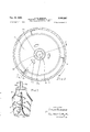
- Fig. 2 is a horizontal sectional view on the line 22 in Fig. l.
- Fig. 3 is a vertical sectional view or part or a modified form of the bowl.
- the centrifuge coznprises a bowl shell lil which supports a central hollow nave H and is, in turn, centrally supported on and rotated by a hollow spindle l2.
- a nut 3 Within the nave ii is a nut 3 for securing the bowl to the spindle.
- a bowl top it is secured to the upper part of the shell by a coupling ring l5 and forms a bowl neck I la.
- a stack of conical discs I? is mounted the separating chamber of the bowl, the discs being separated by the usual caulks (not shown) to form thin separating spaces between the discs. It will be understood that the discs are spaced closely together, although for the purpose of clarity I have omitted some of the discs in Fig. l of the drawings.
- the discs have central holes Ha, the edges of which define a free central space in a separating chamber of the bowl. That is, the central space i8 provides unobstructed communication between the rotation axis of the bowl and the discs i'i. Since the inner edges of the discs are free, I provide outside the central space it means for centering the discs in the howl and driving them at the same speed as the bowl.
- Such means comprise circumferentially spaced wings i9 welded or otherwise secured to the bowl periphery.
- the wings extend radially inward into engagement with the outer edges of the discs, which are formed with notches i'lb for receiving the inner edge of one of the wings is and thereby form a driving connection between the bowl and the disc stack.
- the whole milk is fed into a central passage !2a in the spindle E2.
- the upper portion of the spindle is tapered and fits closely in the bottom of the bowl.
- the spindle serves as an axial feed pipe having an air-tight connection with the bowl.
- the whole milk is delivered under pressure into the lower end of the spindle from a fixed pipe through a conventional sealed connection (not shown) such as that illustrated in Lindgren Patent No. 1,901,461. From the hoilow spindle E2, the whole milk passes through openings 83a in the nut i3 into a feed chamber Ha formed by the nave H.
- Hollow tubes 26 extend from the wall of the nave into the inner part of the feed chamber i la and form feed passages leading upward and outward to vertically aligned distributing holes I 'ie in the discs, these holes being located a short distance outward from the central free space 18.
- a top disc 22 forming a 4 central outlet passage 22a leading upward through an inner neck 2% from thecentral free space it.
- the central neck or tube 221) of the top disc extends upward into a stationary head 23 mounted on the frame of the centrifuge, and it communicates with a stationary discharge pipe 2-1 secured to the head.
- a stationary discharge pipe 2-1 secured to the head.
- an air-tight seal comprising rubber rings or packings 25 closely surrounding the tube 2213 and held within the stationary head 23. In this way, a closed path is provided for the separated cream from the upper end of the free central space it through the central outlet passage 22a to the discharge pipe 24.
- the top disc 22 forms with the bowl top M a number of passages 25 extending inwardly and upwardly from the outer zone of the separating chamber at the region of the outer edges or the discs 11.
- the passages 26, which may be sepa rated from each other by wings on one of the members l4 and 22, extend between the tube 22d and the neck Ma, the passages opening into a space 23a in the head 23.
- the space communicates with a fixed discharge pipe 2? for the skim milk or heavy component.
- Between the discharge pipe 21 and the bowl is an air tight seal comprising the rings 25 above the space 230. and a rubber packing or ring 28 below this space.
- the ring 28 closely surrounds the neck M a and is secured between the head 23 and the stationar cover 29.
- a nut 30 is threaded centrally in the upper part of the nave It and serves to assist in the removal, as a unit, of the stack of discs ll from the bowl.
- a hook may be inserted through the central free space it; within the disc stack to grasp the underside of the nut or the nut may be removed and a lifting tool thi ed in its place.
- the closed oath previously des' rated cream is displace, free space it within the disc stack.
- feed pressure is effective to force or viscous cream upwardly into thro cream path leading to discharge .ic cream flow.
- a cenl: feed passage may formed it of the nave ii and nut so t i; the l ad pressure will cause a relatively small amount 0 the feed to enter dire tly into the of th free central space iii with a jet -t to assist It will be understood that accordng to invention the centrifugal separation of cold in (or other products in which the separated li 5 pipes to the bowl and the free central space 18 Within the disc stack.
- the disc-supporting wings 19 may be formed with holes 19a near the outlet passages 23, for circulation of the skim milk component. Also, the rate of discharge of separated cream may be con-- trolled by a valve system in pipe 24, as disclosed in Hapgood Patent No. 2,160,140.
- the free space 35a within the discs does not extend inwardly as far as the rotation axis of the bowl, as in the previously described form. Instead, the free space 18a surrounds as axial upwardly-tapered shaft 32 of small diameter which is supported by and rotates with the nave II.
- the shaft 32 is secured to the top of the nave (in place of the nut 30 illustrated in Figs. 1 and 2) and extends upwardly toward the outlet passage 22a throughout most of the vertical extent of the free space 18a.
- a wing 32a of the Archimedes screw type is secured to the periphery of shaft 32 and spirals upwardly around shaft in the same direction as the rotation of the bowl.
- the wing 32a acts to force the cream upwardly toward the discharge passage 22a and thereby supplement the feed pressure in expelling the cream from the bowl.
- a rotatable centrifugal bowl having a separating chamber, a stack of conical discs in the chamber forming thin separating spaces between the discs, the discs having central holes and the bowl chamber having within the edges of said holes a free space providing unobstructed communication inwardly from said edges toward the rotation axis of the bowl, said free inner space extending continuously through the disc stack and continuously around said edges, means outside said free space engaging the discs and forming a driving connection between the bowl and the discs, an axial feed pipe having an air-tight connection with the bowl, the bowl having a feed passage communicating with said pipe for leading the feed to the disc stack at a region spaced outwardly from said free space, the bowl also having a central light component outlet passage leading from one end of said free space and a heavy component outlet passage leading from the outer part of the separating chamber, a stationary discharge pipe outside the bowl and communicating with the central outlet passage, and an air-tight seal between the discharge pipe and the bowl to
- said disc engaging means include a wing extending generally radially from the outer edges of the discs to the bowl periphery and engaged in peripheral notches in the discs to form said driving connection.
- the bowl also has a feed chamber between the feedpipe and said feed passage, and a hollow tube extending into the inner part of the feed chamber and forming said feed passage.
- Th combination according to claim 1 comprising also a hollow nave in the bowl forming a feed chamber between the feed pipe and the feed passage, the nave having a narrow central top opening forming a jet feed passage leading directly into the lower end of said free space, said central outlet passage leading from the upper end of said free space.
Description
Dec. 15, 1953 Filed April 1 1950 oss 2,662,687
H. M. SPR CENTRIFUGAL SEPARATOR FOR COLD MILK PRODUCTS AND THE LIKE 2 Sheets-Sheet l \/E /\1 TOP HUBER T M $1 2066 ATTORNE .s
De c. 15, 1953 sp oss 2,662,687
CENTRIFUGAL SEPARATOR FOR COLD MILK PRODUCTS AND THE LIKE Filed April 1, 1950 2 Sheets-Sheet 2 N VE N TOP HUBER T118320 15's ATTORNEYS Patented Dec. 15, 1953 UNITED srATss CENTRIFUGAL SEPARATOR FOR COLD MILK PRODUCTS AND THE LIKE ELTENT OFFICE Application April 1, 1950, Serial No. 153,408
6 Claims. (Cl. 233=-21) This invention relates to centrifuges for separating liquids according to their relative specific gravities, and it has for its principal object the provision of an improved centrifuge adapted especially for the continuous separation of cream from whole milk at low temperature.
It has long been the general and accepted practice in dairy plants to heat milk, immediately prior to centrifugal separation, to a temperature of 90 TEE-92 F. Within this temperature range, the viscosity of the separated cream is sufficiently low to permit its exit from the centrifugal bowl without clogging due to buttering, a phenomenon well known in the art of separating whole milk into its cream and skim milk COillponents.
The disadvantages of milk separation within this usual and somewhat elevated temperature range are two-fold. There is the added expense for the heating equipment itself and its operation to maintain the milk at the prescribed tem perature, and there is a resulting loss of casein from the skim milk. Since some casein in the form of colloidal calcium caseinate begins to precipitate and be centrifugally separable from the whole milk at a temperature of 70 F., any heating beyond this point results in an increasing loss in valuable casein lay-products manufactured from the separated skim milk. This loss occurs because the casein is separated as a solid and collects on the bowl wall together with other separated impurity solids. When the bowl is cleaned, the separated solids are thrown away.
With the centrifuge of the present invention, the whole milk can be separated continuously at a temperature within the range of 40 F. to 50 and the inherent tendency of the highly viscous separated cream component to clog the bow overcome or, at least, greatly reduced.
A. centrifuge made according to the invention comprises a stack of conical discs located in the separating chamber of a rotatable centrifugal bowl and forming thin separating spaces between the discs. The discs have central holes, and the bowl chamber has within the edges of these holes a free space which provides unobstructed C0i'llmunicaticn inwardly from the discs toward the rotation axi of the bowl. In order to rotate the discs at the same speed as the bowl, means are provided outside this free space which engage the discs and term a driving connection between the bowl and the discs. The milk product is fed to the separating chamber through an axial feed pipe having an air-tight connection with the bowl, the milk product being delivered from the feed pipe through a feed passage leading to the disc stack at a region spaced outwardly from the free space within the discs. The separated light component or cream is displaced inwardly from the discs into the free space, where it passes without obstruction into a central outlet passage leading from one end of this free space. The skim milk or heavy component separated between the discs passes to the outer part of the bowl and then into a second outlet passage. A stationary discharge pipe outside the bowl cornmunicates with the central or cream outlet passage, and an air-tight seal is provided between the discharge pipe and the bowl to form a closed path from the free space within the discs through the central outlet passage to the discharge pipe. Preferably, the skim milk outlet passage also communicates through an air-tight seal with a second stationary discharge pipe outside the bowl.
By virtue of this combination of air-tight connections with the bowl for the feed and discharge and the free space within the inner edges of the discs, the separated cream can be discharged from the bowl under pressure without clogging it, even when the separated cream component is at relatively low temperature and has a high viscosity. The sealed connections with the bowl for the feed and the discharge enable the use of a relatively high pressure at the inlet side of the bowl, and because of the absence of the usual tubular shaft, disc support, or other obstruction at the inner edges of the discs, the relatively high pressure feed of the milk product is made eifective to force the separated cream from the bowl in a continuous stream. In some cases, it is advantageous to provide a branch feed passage leading from the feed pipe directly to the free space within the discs, at the end of this space opposite the central discharge outlet for the cream component, so that some of the milk prodnot is forced under pressure into the free space with a jet action to facilitate further the dis charge of the viscous cream.
In the preferred construction, the milk product is fed from the feed pipe into a feed chamber formed by a hollow nave in the bowl, and a hollow tube extends into the inner part of the feed chamber to form a feed passage leading to a set of distributing holes in the discs located some distance outwardly from the free inner edges of the discs. In this way, the milk product is delivered to the disc spaces substantially free of turbulence. Also, the discs are preferably centered in the bowl by radial wings extending inwardly from the bowl periphery and engaging the outer edges of the discs, the latter having notches for receiving the inner edge or one of he wings to provide the driving connection be tween the bowl and the disc stack. The wings may be formed with openings to permit circulation of the separated skim milk in the outer part or the bowl, in the vicinity of the outlet passage for the skim milk.
In one form of the new centrifuge, the free space within the discs surrounds a tapered axial shaft which supplements the high feed pressure in discharging the viscous cream through the free space.
For a better understanding or the invention reference may be had to the accompanying drawings, in which Fig. 1 is a vertical sectional view of a preferred form of the new centrifuge;
Fig. 2 is a horizontal sectional view on the line 22 in Fig. l, and
Fig. 3 is a vertical sectional view or part or a modified form of the bowl.
Referring to the drawings, the centrifuge coznprises a bowl shell lil which supports a central hollow nave H and is, in turn, centrally supported on and rotated by a hollow spindle l2. Within the nave ii is a nut 3 for securing the bowl to the spindle. A bowl top it is secured to the upper part of the shell by a coupling ring l5 and forms a bowl neck I la.
A stack of conical discs I? is mounted the separating chamber of the bowl, the discs being separated by the usual caulks (not shown) to form thin separating spaces between the discs. It will be understood that the discs are spaced closely together, although for the purpose of clarity I have omitted some of the discs in Fig. l of the drawings. The discs have central holes Ha, the edges of which define a free central space in a separating chamber of the bowl. That is, the central space i8 provides unobstructed communication between the rotation axis of the bowl and the discs i'i. Since the inner edges of the discs are free, I provide outside the central space it means for centering the discs in the howl and driving them at the same speed as the bowl. Such means, as shown, comprise circumferentially spaced wings i9 welded or otherwise secured to the bowl periphery. The wings extend radially inward into engagement with the outer edges of the discs, which are formed with notches i'lb for receiving the inner edge of one of the wings is and thereby form a driving connection between the bowl and the disc stack.
The whole milk is fed into a central passage !2a in the spindle E2. The upper portion of the spindle is tapered and fits closely in the bottom of the bowl. Thus, the spindle serves as an axial feed pipe having an air-tight connection with the bowl. The whole milk is delivered under pressure into the lower end of the spindle from a fixed pipe through a conventional sealed connection (not shown) such as that illustrated in Lindgren Patent No. 1,901,461. From the hoilow spindle E2, the whole milk passes through openings 83a in the nut i3 into a feed chamber Ha formed by the nave H. Hollow tubes 26 extend from the wall of the nave into the inner part of the feed chamber i la and form feed passages leading upward and outward to vertically aligned distributing holes I 'ie in the discs, these holes being located a short distance outward from the central free space 18.
Above the discs I! is a top disc 22 forming a 4 central outlet passage 22a leading upward through an inner neck 2% from thecentral free space it. The central neck or tube 221) of the top disc extends upward into a stationary head 23 mounted on the frame of the centrifuge, and it communicates with a stationary discharge pipe 2-1 secured to the head. Between the discharge pipe 24 and the bowl is an air-tight seal comprising rubber rings or packings 25 closely surrounding the tube 2213 and held within the stationary head 23. In this way, a closed path is provided for the separated cream from the upper end of the free central space it through the central outlet passage 22a to the discharge pipe 24.
The top disc 22 forms with the bowl top M a number of passages 25 extending inwardly and upwardly from the outer zone of the separating chamber at the region of the outer edges or the discs 11. The passages 26, which may be sepa rated from each other by wings on one of the members l4 and 22, extend between the tube 22d and the neck Ma, the passages opening into a space 23a in the head 23. The space communicates with a fixed discharge pipe 2? for the skim milk or heavy component. Between the discharge pipe 21 and the bowl is an air tight seal comprising the rings 25 above the space 230. and a rubber packing or ring 28 below this space. The ring 28 closely surrounds the neck M a and is secured between the head 23 and the stationar cover 29. Thus, a closed path for discharging the separated skim milk is provided from the outer part of the separating chamber through passages 26, head 23 and discharge pipe 2?, and this path is sealed from the discharge path for the cream.
A nut 30 is threaded centrally in the upper part of the nave It and serves to assist in the removal, as a unit, of the stack of discs ll from the bowl. When the bowl is opened fOr cleaning, by removing the top i i, a hook may be inserted through the central free space it; within the disc stack to grasp the underside of the nut or the nut may be removed and a lifting tool thi ed in its place.
the closed oath previously des' rated cream is displace, free space it within the disc stack.
feed pressure is effective to force or viscous cream upwardly into thro cream path leading to discharge .ic cream flow. If desired, a cenl: feed passage may formed it of the nave ii and nut so t i; the l ad pressure will cause a relatively small amount 0 the feed to enter dire tly into the of th free central space iii with a jet -t to assist It will be understood that accordng to invention the centrifugal separation of cold in (or other products in which the separated li 5 pipes to the bowl and the free central space 18 Within the disc stack. By centering and driving the discs from the outside, instead of from the inside as in conventional designs, the highly vis- 'cous cream is forced through the central part of the bowl by the feed pump without contacting any rotating part in the space it, which would tend to agitate the cream and impede the action of the feed pressure in discharging it. It will be noted that the inner flange of each disc 1? is in a horizontal plane and presents an unbroken surface to the flow of the cream component.
The disc-supporting wings 19 may be formed with holes 19a near the outlet passages 23, for circulation of the skim milk component. Also, the rate of discharge of separated cream may be con-- trolled by a valve system in pipe 24, as disclosed in Hapgood Patent No. 2,160,140.
In the modified form of the bowl illustrated in Fig. 3, the free space 35a within the discs does not extend inwardly as far as the rotation axis of the bowl, as in the previously described form. Instead, the free space 18a surrounds as axial upwardly-tapered shaft 32 of small diameter which is supported by and rotates with the nave II. The shaft 32 is secured to the top of the nave (in place of the nut 30 illustrated in Figs. 1 and 2) and extends upwardly toward the outlet passage 22a throughout most of the vertical extent of the free space 18a. A wing 32a of the Archimedes screw type is secured to the periphery of shaft 32 and spirals upwardly around shaft in the same direction as the rotation of the bowl. Thus, since the cream in the free space 18:; rotates at a higher angular speed than the bowl, due to run-ahead between the cream and the bowl, the wing 32a acts to force the cream upwardly toward the discharge passage 22a and thereby supplement the feed pressure in expelling the cream from the bowl.
While I prefer the use of the helical wing 320. on the shaft 32, this wing can be eliminated if desired. The upward taper of the shaft 32, in conjunction with the high feed pressure, serves in itself to facilitate discharge of the cream from the free space Hm.
I claim:
1. In an air-tight centrifuge, the combination of a rotatable centrifugal bowl having a separating chamber, a stack of conical discs in the chamber forming thin separating spaces between the discs, the discs having central holes and the bowl chamber having within the edges of said holes a free space providing unobstructed communication inwardly from said edges toward the rotation axis of the bowl, said free inner space extending continuously through the disc stack and continuously around said edges, means outside said free space engaging the discs and forming a driving connection between the bowl and the discs, an axial feed pipe having an air-tight connection with the bowl, the bowl having a feed passage communicating with said pipe for leading the feed to the disc stack at a region spaced outwardly from said free space, the bowl also having a central light component outlet passage leading from one end of said free space and a heavy component outlet passage leading from the outer part of the separating chamber, a stationary discharge pipe outside the bowl and communicating with the central outlet passage, and an air-tight seal between the discharge pipe and the bowl to provide a closed path from said free space through the central outlet passage to the discharge pipe.
2. The combination according to claim 1, in which said disc engaging means include a wing extending generally radially from the outer edges of the discs to the bowl periphery and engaged in peripheral notches in the discs to form said driving connection.
3. The combination according to claim 1, in which the bowl also has a narrow branch feed passage communicating with the feed pipe and forming a jet leading directly to the end of said free space opposite the central outlet.
4. The combination according to claim 1, in which the bowl also has a feed chamber between the feedpipe and said feed passage, and a hollow tube extending into the inner part of the feed chamber and forming said feed passage.
5. Th combination according to claim 1, comprising also a hollow nave in the bowl forming a feed chamber between the feed pipe and the feed passage, the nave having a narrow central top opening forming a jet feed passage leading directly into the lower end of said free space, said central outlet passage leading from the upper end of said free space.
6. The combination according to claim 1, in which said free space extends inwardly from the discs to the rotation axis of the bowl.
HUBERT M. SPROSS.
References Cited in the file of this patent UNITED STATES PATENTS Number Name Date 547,404 Springer Oct. 1, 1895 1,422,856 Hapgood July 18, 1922 1,427,486 Lindgren Aug. 29, 1922 1,916,870 Strezynski July 4, 1933 1,945,336 Strezynski Jan. 30, 1934 2,002,954 Lindgren May 28, 1935 2,089,043 Svensto Aug. 3, 1937 2,089,122 Jones -2 Aug. 3, 1937 2,173,580 Fawcett Sept. 19, 1939 2,222,727 Stigen Nov. 26, 1940 FOREIGN PATENTS Number Country Date 476,823 Great Britain Dec. 16, 1937
Priority Applications (2)
| Application Number | Priority Date | Filing Date | Title |
|---|---|---|---|
| US153408A US2662687A (en) | 1950-04-01 | 1950-04-01 | Centrifugal separator for cold milk products and the like |
| US313462A US2668008A (en) | 1950-04-01 | 1952-10-07 | Centrifugal separator for cold milk products and the like |
Applications Claiming Priority (1)
| Application Number | Priority Date | Filing Date | Title |
|---|---|---|---|
| US153408A US2662687A (en) | 1950-04-01 | 1950-04-01 | Centrifugal separator for cold milk products and the like |
Publications (1)
| Publication Number | Publication Date |
|---|---|
| US2662687A true US2662687A (en) | 1953-12-15 |
Family
ID=22547102
Family Applications (1)
| Application Number | Title | Priority Date | Filing Date |
|---|---|---|---|
| US153408A Expired - Lifetime US2662687A (en) | 1950-04-01 | 1950-04-01 | Centrifugal separator for cold milk products and the like |
Country Status (1)
| Country | Link |
|---|---|
| US (1) | US2662687A (en) |
Cited By (17)
| Publication number | Priority date | Publication date | Assignee | Title |
|---|---|---|---|---|
| US2717119A (en) * | 1951-11-03 | 1955-09-06 | Sharples Corp | Centrifugal separator |
| US4285462A (en) * | 1979-01-09 | 1981-08-25 | Robatel S.L.P.I. | Centrifuges with hydraulic controls |
| US4692136A (en) * | 1985-10-11 | 1987-09-08 | Cardiovascular Systems Inc. | Centrifuge |
| US4718888A (en) * | 1986-03-10 | 1988-01-12 | Cardiovascular Systems, Inc. | Centrifuge bowl mount |
| US4795419A (en) * | 1985-10-11 | 1989-01-03 | Kardiothor, Inc. | Centrifuge |
| AU592598B2 (en) * | 1985-10-11 | 1990-01-18 | Cobe Laboratories Inc. | Centrifuge |
| EP0363120A2 (en) * | 1988-10-07 | 1990-04-11 | Baxter International Inc. | Centrifugal fluid processing system and method |
| US4936821A (en) * | 1986-11-05 | 1990-06-26 | Frau S.P.A. | Centrifugal separator with rotating seals on the fixed upper head |
| US4936820A (en) * | 1988-10-07 | 1990-06-26 | Baxter International Inc. | High volume centrifugal fluid processing system and method for cultured cell suspensions and the like |
| US5006103A (en) * | 1977-08-12 | 1991-04-09 | Baxter International Inc. | Disposable container for a centrifuge |
| US5078671A (en) * | 1988-10-07 | 1992-01-07 | Baxter International Inc. | Centrifugal fluid processing system and method |
| US5217426A (en) * | 1977-08-12 | 1993-06-08 | Baxter International Inc. | Combination disposable plastic blood receiving container and blood component centrifuge |
| US5217427A (en) * | 1977-08-12 | 1993-06-08 | Baxter International Inc. | Centrifuge assembly |
| US5571068A (en) * | 1977-08-12 | 1996-11-05 | Baxter International Inc. | Centrifuge assembly |
| US6533713B1 (en) * | 1998-08-20 | 2003-03-18 | Alfa Laval Ab | Entraining device for a centrifugal separator |
| DE102004042888A1 (en) * | 2004-09-04 | 2006-03-23 | Westfalia Separator Ag | Self-draining separator with disc package |
| US20110212821A1 (en) * | 2008-05-13 | 2011-09-01 | Gea Westfalia Separator Gmbh | Centrifuge having a drum provided with a separator disk package |
Citations (11)
| Publication number | Priority date | Publication date | Assignee | Title |
|---|---|---|---|---|
| US547404A (en) * | 1895-10-01 | Thomas ii | ||
| US1422856A (en) * | 1922-07-18 | Centrifugal machine | ||
| US1427486A (en) * | 1922-05-24 | 1922-08-29 | Separator Ab | Supporting strip for conical liner plates in the bowl of centrifugal separators |
| US1916870A (en) * | 1931-06-25 | 1933-07-04 | Laval Separator Co De | Centrifucal bowl |
| US1945336A (en) * | 1930-08-01 | 1934-01-30 | Laval Separator Co De | Centrifugal separator bowl |
| US2002954A (en) * | 1930-12-15 | 1935-05-28 | Laval Separator Co De | Centrifugal separator |
| US2089122A (en) * | 1934-11-03 | 1937-08-03 | Sharples Specialty Co | Apparatus for separating wax from oil |
| US2089043A (en) * | 1935-01-09 | 1937-08-03 | Laval Separator Co De | Process of purifying fruit juices |
| GB476823A (en) * | 1935-09-06 | 1937-12-16 | Bergedorfer Eisenwerk Ag | Improvements in centrifugal separators |
| US2173580A (en) * | 1936-02-21 | 1939-09-19 | Fawcett Harold William | Centrifugal separator |
| US2222727A (en) * | 1937-11-12 | 1940-11-26 | Laval Separator Co De | Process of effecting clean skimming in separating milk from cream and in centrifuges for practicing such method |
-
1950
- 1950-04-01 US US153408A patent/US2662687A/en not_active Expired - Lifetime
Patent Citations (11)
| Publication number | Priority date | Publication date | Assignee | Title |
|---|---|---|---|---|
| US547404A (en) * | 1895-10-01 | Thomas ii | ||
| US1422856A (en) * | 1922-07-18 | Centrifugal machine | ||
| US1427486A (en) * | 1922-05-24 | 1922-08-29 | Separator Ab | Supporting strip for conical liner plates in the bowl of centrifugal separators |
| US1945336A (en) * | 1930-08-01 | 1934-01-30 | Laval Separator Co De | Centrifugal separator bowl |
| US2002954A (en) * | 1930-12-15 | 1935-05-28 | Laval Separator Co De | Centrifugal separator |
| US1916870A (en) * | 1931-06-25 | 1933-07-04 | Laval Separator Co De | Centrifucal bowl |
| US2089122A (en) * | 1934-11-03 | 1937-08-03 | Sharples Specialty Co | Apparatus for separating wax from oil |
| US2089043A (en) * | 1935-01-09 | 1937-08-03 | Laval Separator Co De | Process of purifying fruit juices |
| GB476823A (en) * | 1935-09-06 | 1937-12-16 | Bergedorfer Eisenwerk Ag | Improvements in centrifugal separators |
| US2173580A (en) * | 1936-02-21 | 1939-09-19 | Fawcett Harold William | Centrifugal separator |
| US2222727A (en) * | 1937-11-12 | 1940-11-26 | Laval Separator Co De | Process of effecting clean skimming in separating milk from cream and in centrifuges for practicing such method |
Cited By (21)
| Publication number | Priority date | Publication date | Assignee | Title |
|---|---|---|---|---|
| US2717119A (en) * | 1951-11-03 | 1955-09-06 | Sharples Corp | Centrifugal separator |
| US5759147A (en) * | 1977-08-12 | 1998-06-02 | Baxter International Inc. | Blood separation chamber |
| US5217426A (en) * | 1977-08-12 | 1993-06-08 | Baxter International Inc. | Combination disposable plastic blood receiving container and blood component centrifuge |
| US5006103A (en) * | 1977-08-12 | 1991-04-09 | Baxter International Inc. | Disposable container for a centrifuge |
| US5571068A (en) * | 1977-08-12 | 1996-11-05 | Baxter International Inc. | Centrifuge assembly |
| US5217427A (en) * | 1977-08-12 | 1993-06-08 | Baxter International Inc. | Centrifuge assembly |
| US4285462A (en) * | 1979-01-09 | 1981-08-25 | Robatel S.L.P.I. | Centrifuges with hydraulic controls |
| US4795419A (en) * | 1985-10-11 | 1989-01-03 | Kardiothor, Inc. | Centrifuge |
| AU592598B2 (en) * | 1985-10-11 | 1990-01-18 | Cobe Laboratories Inc. | Centrifuge |
| US4692136A (en) * | 1985-10-11 | 1987-09-08 | Cardiovascular Systems Inc. | Centrifuge |
| US4718888A (en) * | 1986-03-10 | 1988-01-12 | Cardiovascular Systems, Inc. | Centrifuge bowl mount |
| US4936821A (en) * | 1986-11-05 | 1990-06-26 | Frau S.P.A. | Centrifugal separator with rotating seals on the fixed upper head |
| EP0363120A2 (en) * | 1988-10-07 | 1990-04-11 | Baxter International Inc. | Centrifugal fluid processing system and method |
| US4936820A (en) * | 1988-10-07 | 1990-06-26 | Baxter International Inc. | High volume centrifugal fluid processing system and method for cultured cell suspensions and the like |
| US5078671A (en) * | 1988-10-07 | 1992-01-07 | Baxter International Inc. | Centrifugal fluid processing system and method |
| EP0363120A3 (en) * | 1988-10-07 | 1991-01-23 | Baxter International Inc. | Centrifugal fluid processing system and method |
| US6533713B1 (en) * | 1998-08-20 | 2003-03-18 | Alfa Laval Ab | Entraining device for a centrifugal separator |
| US20070270298A1 (en) * | 2004-09-04 | 2007-11-22 | Westfalia Separator Ag | Self-dumping separator with a disk stack |
| DE102004042888A1 (en) * | 2004-09-04 | 2006-03-23 | Westfalia Separator Ag | Self-draining separator with disc package |
| US8734311B2 (en) * | 2008-05-13 | 2014-05-27 | Gea Westfalia Separator Gmbh | Centrifuge having tubular elements on an outside circumference of a disk package |
| US20110212821A1 (en) * | 2008-05-13 | 2011-09-01 | Gea Westfalia Separator Gmbh | Centrifuge having a drum provided with a separator disk package |
Similar Documents
| Publication | Publication Date | Title |
|---|---|---|
| US2662687A (en) | Centrifugal separator for cold milk products and the like | |
| EP0221723B1 (en) | Centrifuge rotor inlet device | |
| US4015773A (en) | Centrifuge for separating solids from liquids | |
| US2628021A (en) | Centrifuge with auxiliary feed arrangement | |
| US10894259B2 (en) | Separator with a double-conical centrifuging chamber | |
| US2500100A (en) | Centrifugal bowl | |
| US3777972A (en) | Sludge centrifuge | |
| US2668008A (en) | Centrifugal separator for cold milk products and the like | |
| US2478992A (en) | Centrifugal bowl | |
| US2958461A (en) | Centrifuge machine | |
| US3924804A (en) | Centrifuge for the separation of mixtures of liquids | |
| US3129175A (en) | Centrifuges | |
| US2645415A (en) | Centrifugal bowl | |
| US3199681A (en) | Centrifuge | |
| US2485209A (en) | Centrifuge with primary and secondary zones of separation and process therefor | |
| US2717119A (en) | Centrifugal separator | |
| SE459159B (en) | Centrifugal separator with fatigue organ | |
| US3250462A (en) | Method and apparatus for sludge concentration by centrifugation | |
| US690883A (en) | Centrifugal liquid-separator. | |
| US4065393A (en) | Conical centrifuge with continuous action | |
| US1482229A (en) | Machine fob | |
| US2294468A (en) | Centrifugal separator | |
| US1916870A (en) | Centrifucal bowl | |
| US1113005A (en) | Cream-separator. | |
| US2629547A (en) | Power washing centrifugal separator |