US2630532A - Directed beam antenna system - Google Patents
Directed beam antenna system Download PDFInfo
- Publication number
- US2630532A US2630532A US34433A US3443348A US2630532A US 2630532 A US2630532 A US 2630532A US 34433 A US34433 A US 34433A US 3443348 A US3443348 A US 3443348A US 2630532 A US2630532 A US 2630532A
- Authority
- US
- United States
- Prior art keywords
- reflector
- dipole
- antenna system
- conductor
- axis
- Prior art date
- Legal status (The legal status is an assumption and is not a legal conclusion. Google has not performed a legal analysis and makes no representation as to the accuracy of the status listed.)
- Expired - Lifetime
Links
Images
Classifications
-
- H—ELECTRICITY
- H01—ELECTRIC ELEMENTS
- H01Q—ANTENNAS, i.e. RADIO AERIALS
- H01Q3/00—Arrangements for changing or varying the orientation or the shape of the directional pattern of the waves radiated from an antenna or antenna system
- H01Q3/12—Arrangements for changing or varying the orientation or the shape of the directional pattern of the waves radiated from an antenna or antenna system using mechanical relative movement between primary active elements and secondary devices of antennas or antenna systems
- H01Q3/16—Arrangements for changing or varying the orientation or the shape of the directional pattern of the waves radiated from an antenna or antenna system using mechanical relative movement between primary active elements and secondary devices of antennas or antenna systems for varying relative position of primary active element and a reflecting device
- H01Q3/18—Arrangements for changing or varying the orientation or the shape of the directional pattern of the waves radiated from an antenna or antenna system using mechanical relative movement between primary active elements and secondary devices of antennas or antenna systems for varying relative position of primary active element and a reflecting device wherein the primary active element is movable and the reflecting device is fixed
Definitions
- This invention relates to directed beam antenna systems for developing a periodically changing radiation pattern, and more particularly to the mechanical construction of such antenna systems.
- a method frequently employed in radar for the exact location of a reflecting object is to transmit a radar beam which varies in amplitude according to a club-shaped pattern, and to impart a circular motion to the axis or maximum amplitude line of the beam, whereby the oscillations reflected back from the object are modulated in amplitude according to its position in space.
- the rotation of the radiation pattern is produced by corresponding rotation of a dipole placed eccentrically in the reflector mirror in the neighborhood of the focal point.
- the point of heaviest radiation of the dipole thereby moves in a circle of which the center is the focal point of the reflector, but the arrangements for the conduction of current to the rotating dipole were not entirely satisfactory.
- the periodically changing polarization of the emitted beam of rays of course possesses a rotation corresponding to the dipole rotation. In the guiding of flying objects having, for instance, a dipole as the receiving antenna system, this rotation causes an undesirable additional amplitude modulation of the reception energy, since the direction of the receiving field strength changes periodically in relation to the position of the dipole.
- This additional periodic amplitude modulation causes a deceptive periodically changing error in the indicated position of the flying body which may lead to false course corrections.
- the rotating polarization of the receiving field strength is a drawback since the reflecting object, from its geometric form, has polarization-dependent reflection properties.
- Objects of the present invention are to provide directed beam antenna systems which develop a periodically changing radiation pattern without, however, necessitating a rotation of the radiating antenna or a reversal of antenna currents.
- Objects are to provide directed beam antenna systems including a parabolic reflector, a dipole located in the neighborhood of the focal point of the reflector and supported from the apex of the reflector by a concentric conductor or coaxial line, and mechanism for translating the center of the dipole along a path about the focal point of the reflector without, however, ro-
- Figs. 3 and 4 are fragmentary sectional views of alternative concentric conductor constructions for supporting the dipole for translation along a circular or an elliptical path about the focal point of the reflector.
Description
March 3, 1953 G. GUANELLA DIRECTED BEAM ANTENNA SYSTEM Filed June 22, 1948 Patented Mar. 3, 1953 DIRECTED BEAM ANTENNA SYSTEM Gustav Guanella, Zurich, Switzerland, assignor to Patelhold Patentverwertungs- & Electro- Holding A.-G., Glarus, Switzerland Application June 22, 1948, Serial No. 34,433 In Switzerland July 14, 1947 6 Claims.
This invention relates to directed beam antenna systems for developing a periodically changing radiation pattern, and more particularly to the mechanical construction of such antenna systems.
A method frequently employed in radar for the exact location of a reflecting object is to transmit a radar beam which varies in amplitude according to a club-shaped pattern, and to impart a circular motion to the axis or maximum amplitude line of the beam, whereby the oscillations reflected back from the object are modulated in amplitude according to its position in space.
i In the best known devices, the rotation of the radiation pattern is produced by corresponding rotation of a dipole placed eccentrically in the reflector mirror in the neighborhood of the focal point. The point of heaviest radiation of the dipole thereby moves in a circle of which the center is the focal point of the reflector, but the arrangements for the conduction of current to the rotating dipole were not entirely satisfactory. Furthermore, the periodically changing polarization of the emitted beam of rays of course possesses a rotation corresponding to the dipole rotation. In the guiding of flying objects having, for instance, a dipole as the receiving antenna system, this rotation causes an undesirable additional amplitude modulation of the reception energy, since the direction of the receiving field strength changes periodically in relation to the position of the dipole. This additional periodic amplitude modulation causes a deceptive periodically changing error in the indicated position of the flying body which may lead to false course corrections. In radar instruments, likewise, the rotating polarization of the receiving field strength is a drawback since the reflecting object, from its geometric form, has polarization-dependent reflection properties.
There are also devices in which a periodic pattern variation is imposed upon a constantly polarized beam of rays by a periodic reversing of different individual rays of a composite antenna system. The reversing, which is generally done by capacitive methods, presents considerable difficulties, however, and this method and apparatus have not been entirely satisfactory.
Objects of the present invention are to provide directed beam antenna systems which develop a periodically changing radiation pattern without, however, necessitating a rotation of the radiating antenna or a reversal of antenna currents. Objects are to provide directed beam antenna systems including a parabolic reflector, a dipole located in the neighborhood of the focal point of the reflector and supported from the apex of the reflector by a concentric conductor or coaxial line, and mechanism for translating the center of the dipole along a path about the focal point of the reflector without, however, ro-
tating the dipole about the axis of the reflector.
These and other objects and the advantages of the invention will be apparent from the following specification when taken with the accompanying drawings in which:
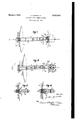
Figs. 1 and 2 are fragmentary sectional views, on planes through the axis of the reflector, of two directed beam antenna systems constituting different embodiments of the invention; and
Figs. 3 and 4 are fragmentary sectional views of alternative concentric conductor constructions for supporting the dipole for translation along a circular or an elliptical path about the focal point of the reflector.
In the drawings, the reference numeral l identifies a parabolic metal reflector having an axis of symmetry yy through the apex X and the focal point Z of the reflector. A concentric conductor comprising an outer cylinder 2 and central rod 3 passes through the apex section of and is rigidly secured to the reflector i. The concentric conductor extends beyond the focal point Z and supports the sections 4, '5 of a dipole antenna substantially in a plane transverse to the reflector axis and passing through the focal point, the dipole section 4 which is secured to the central conductor 3 extending through an opening 6 in the outer conductor 2. A secondary reflect-or or rod I is secured diametrically across the outer end of the outer conductor 2 in the plane of the dipole 4, 5, and projects radially from the conductor 2 by approximately the same amount as the dipole. A shaft 8 is secured to and projects axially from the end of the outer conductor 2, the shaft being journalled in a ball-bearing 9 mounted eccentrically in a cam disk ID on the shaft of a motor Ii. The axis of the motor shaft coincides with the reflector axis y-y, and the motor is supported on a strap or skeleton frame l2 which is secured to the reflector l The concentric conductor 2, 3 is resilient and its inner end is firmly anchored to the reflector i by a relatively heavy plate 13.
The dipole antenna 4, 5 is not rotated about its electrical center during use of the antenna system, but rotation of cam disk H] by motor il effects a displacement of the electrical center of the dipole along a circular path of radiu 1' about the focal point Z. The polarization of the electromagnetic waves reflected from reflector I is not substantially afiected but the axis or line of maximum radiation rotates about the apex X of the reflector I by a small angle determined by the eccentricity r 0f the dipole antenna 4, 5 with respect to the reflector axis yy. The period of circular translatory movements depends upon the motor speed, and the mass of the moving antenna system is preferably compensated by counterweighting the cam disk Ill, a illustrated, diametrically opposite the axis of-the ball bearing 9 for quiet operation and uniform loadingot the hearing. The load on the ball bearing 9 may be materially reduced or compensated by operating the motor l l at a speed dependent upon the resiliency or natural period of oscillation of the resilient concentric conductor 2, 3. In place of the circular path of displacement of the dipole antenna 9, 5, an elliptical path may be developed by guiding the shaft 8, or the ball bearing 9, in a radial slot in the cam disk 10.
The described arrangement of the motor H beyond the focal point Z may affect the radiation pattern, but this action can be eliminated by a construction, as shown in Fig. 2, in which the motor l l is located at the rear of the reflector l. The concentric conductor which support the dipole antenna 3, takes. the form of a resilient tube 2 having a reflector disk 7 mounted on its outer end, and a central tubular conductor 3' within whicha resilient shaft [4 is journalled. Shaft I4 is rotated by a motor 5 1 supported from the mounting plate 13 by a sleeve l5, and the outer end of shaft i4 is secured to a stub shaft l6 carrying an eccentric mass or weight 17 and journalled in ball bearings 93 secured to the reflector disk 5'. the concentric conductor 2', 8 extends through an opening in the motor-mounting sleeve and into the interior of the outer concentric conductor 2'.
Rotation of shaft 44 and the off-center mass l7 develops a circular wobbling travel of the outer end of the coaxial conductors 2, 3 which support the dipole'antenna it, 5, and the speed of motor H preferably is so related to the mass and resiliency of the antenna system that me- 1 chanical resonance results, thereby reducing the power required for flexing of the conductor to move the dipole center along a circular path having its center on the axis of the reflector.
In place of the resilient conductors of Figs.
1 and 2; the mechanical assembly which permits translation of the center of the dipole assembly may include universal joints I9 and 28, respectively, see Fig. 3, in the outer conductor 2a and inner conductor 3a of the coaxial line supporting the dipole antenna. Alternatively, as shown in Fig. 4, the'outer conductor 2?) may be provided with circumferential corrugation 20 adjacent the reflector l to increase the flexibility of the antennasystem. The universal joint or flexible section of the concentric conductor may be located at the rear of the reflector I when the latter has a central opening permitting the movement of the concentric conductor.
It will be apparent that there is considerable latitude in the design and construction of directed beam antenna systems embodying the invention, and that various modifications of the described embodiments fall within the spirit and scope of the invention a set forth in the following claims.
I claim:
1. A directed beam antenna system comprising a stationary parabolic reflector having an axis of symmetry, a resilient concentric conductor having a portion extending through the apex of the reflector and coaxial with said axis of symmetry, means rigidly anchoring said portion of the concentric conductor to said reflector, a dipole supported by said concentric conductor substantially in a plane transverse to said axis and passing through the focal point of said reflector, the outer end of the outer member of said concentric conductor projecting beyond said dipole, and means for displacing the maximum A coupling loop l8 for energizing amplitude axis of the radiated beam at constant speed about and at a constant angle with respect to said axis of symmetry of the reflector; said beam displacing mean comprising a motor having a shaft coaxial with said axis of symmetry, path defining means secured to the motor shaft and rotatable thereby, and means coupling said outer end of the outer concentric conductor to said path-defining means at a point displaced from the axis of symmetry of said reflector, whereby through the flexing of said resilient concentric conductor the electrical center of said dipole i displaced along a path encircling the focal point of the reflector.
2. A directed beam antenna system as recited in claim 1, wherein said beam-displacing means includes means for displacing the electrical center of the dipole along a circular path having a center substantially at the focal point of the reflector.
3. A directed beam antenna system as recited in claim 1, wherein the outer member of said concentric conductor is provided with circumferential corrugations adjacent the apex of said reflector to increase the flexibility thereof.
4. A directed beam antenna system as recited in claim 1, wherein said motor is located beyond the focal point of said reflector, as viewed from the apex thereof; and said path defining means comprises a cam disk on said motor shaft, and said coupling means comprises means journalling the outer end of said outer concentric conductor member on and eccentrically of said cam disk.
5. A directed beam antenna system as recited in claim 4, wherein said cam disk includes a counterweight portion at the side of the motor shaft opposite said journalling means.
6. A directed beam antenna system as recited in claim 1, wherein said motor is located at the rear of said reflector and its shaft is resilient, the inner concentric conductor is tubular and said motor shaft extends through the same to project beyond said concentric conductor; said path-determining means is an off-center weight secured to the projecting end of said shaft; and said coupling means comprises a bearingfor the shaft and rigidly supported by said end of the outer concentric conductor member.
GUSTAV GUAN ELLA.
REFERENCES CITED The following references are of record in the file of this patent:
UNITED STATES PATENTS Number Name Date 403,997 Griflin May 28, 1889 1,548,958 Sperry Aug. 11, 1925 1,918,358 Walton July 18, 1933 2,082,347 Leib June 1, 1937 2,410,666 Leck Nov. 5, 1946 2,412,867 Briggs et a1. Dec. 17, 1946 2,420,007 Olden May 6, 1947 2,457,562 Karleen Dec. 28, 1948 2,464,394 Herzlinger Mar. 15, 1949 2,478,913 Goldberg Aug. 16, 1949 2,498,056 Werner Feb. 21, 1950 2,509,283 Wolf May 30, 1950 2,587,995 Griggs Mar. 4, 1952 FOREIGN PATENTS Number Country Date 581,570 Great Britain Oct. 17, 1946 595,349 Great Britain 1 Dec. 3, 1947
Applications Claiming Priority (1)
| Application Number | Priority Date | Filing Date | Title |
|---|---|---|---|
| CH2630532X | 1947-07-14 |
Publications (1)
| Publication Number | Publication Date |
|---|---|
| US2630532A true US2630532A (en) | 1953-03-03 |
Family
ID=4570666
Family Applications (1)
| Application Number | Title | Priority Date | Filing Date |
|---|---|---|---|
| US34433A Expired - Lifetime US2630532A (en) | 1947-07-14 | 1948-06-22 | Directed beam antenna system |
Country Status (1)
| Country | Link |
|---|---|
| US (1) | US2630532A (en) |
Cited By (5)
| Publication number | Priority date | Publication date | Assignee | Title |
|---|---|---|---|---|
| US2741746A (en) * | 1951-10-24 | 1956-04-10 | John C Rankin | High frequency attenuating device |
| DE1000472B (en) * | 1953-09-19 | 1957-01-10 | Iapatelholdia Patentverwertung | Antenna system in which the radiating element moves on a circular path |
| US2864083A (en) * | 1954-04-22 | 1958-12-09 | Sanders Associates Inc | Directional antenna with conical scanning |
| US3312975A (en) * | 1963-08-20 | 1967-04-04 | Sylvania Electric Prod | Antenna nutation mechanism with polarization control |
| US20070019743A1 (en) * | 2002-10-01 | 2007-01-25 | Avocent Corporation | Video compression encoder |
Citations (15)
| Publication number | Priority date | Publication date | Assignee | Title |
|---|---|---|---|---|
| US403997A (en) * | 1889-05-28 | griffin | ||
| US1548958A (en) * | 1921-05-04 | 1925-08-11 | Elmer A Sperry | Aviation beacon |
| US1918358A (en) * | 1931-02-19 | 1933-07-18 | Walton George William | Scanning device for television and the like |
| US2082347A (en) * | 1932-11-29 | 1937-06-01 | Telefunken Gmbh | Radio direction system |
| GB581570A (en) * | 1943-02-15 | 1946-10-17 | Edward Cecil Cork | Improvements in radiation projection systems |
| US2410666A (en) * | 1941-06-14 | 1946-11-05 | Rca Corp | Orienting mechanism for pulse echo systems |
| US2412867A (en) * | 1943-11-10 | 1946-12-17 | Westinghouse Electric Corp | Search system for radio locators |
| US2420007A (en) * | 1944-09-30 | 1947-05-06 | Rca Corp | Flexible joint for waveguides |
| GB595349A (en) * | 1941-11-01 | 1947-12-03 | British Thomson Houston Co Ltd | Improved means for effecting the displacement of an object in a circular path |
| US2457562A (en) * | 1945-07-09 | 1948-12-28 | Bell Telephone Labor Inc | Antenna drive mechanism |
| US2464394A (en) * | 1946-06-26 | 1949-03-15 | Rca Corp | Nutating mechanism |
| US2478913A (en) * | 1944-02-07 | 1949-08-16 | Stromberg Carlson Co | Dipole antenna |
| US2498056A (en) * | 1946-12-20 | 1950-02-21 | Frank D Werner | Nutator |
| US2509283A (en) * | 1945-10-25 | 1950-05-30 | Rca Corp | Directive antenna system |
| US2587995A (en) * | 1943-10-05 | 1952-03-04 | Us Navy | System for guiding airplanes in flight |
-
1948
- 1948-06-22 US US34433A patent/US2630532A/en not_active Expired - Lifetime
Patent Citations (15)
| Publication number | Priority date | Publication date | Assignee | Title |
|---|---|---|---|---|
| US403997A (en) * | 1889-05-28 | griffin | ||
| US1548958A (en) * | 1921-05-04 | 1925-08-11 | Elmer A Sperry | Aviation beacon |
| US1918358A (en) * | 1931-02-19 | 1933-07-18 | Walton George William | Scanning device for television and the like |
| US2082347A (en) * | 1932-11-29 | 1937-06-01 | Telefunken Gmbh | Radio direction system |
| US2410666A (en) * | 1941-06-14 | 1946-11-05 | Rca Corp | Orienting mechanism for pulse echo systems |
| GB595349A (en) * | 1941-11-01 | 1947-12-03 | British Thomson Houston Co Ltd | Improved means for effecting the displacement of an object in a circular path |
| GB581570A (en) * | 1943-02-15 | 1946-10-17 | Edward Cecil Cork | Improvements in radiation projection systems |
| US2587995A (en) * | 1943-10-05 | 1952-03-04 | Us Navy | System for guiding airplanes in flight |
| US2412867A (en) * | 1943-11-10 | 1946-12-17 | Westinghouse Electric Corp | Search system for radio locators |
| US2478913A (en) * | 1944-02-07 | 1949-08-16 | Stromberg Carlson Co | Dipole antenna |
| US2420007A (en) * | 1944-09-30 | 1947-05-06 | Rca Corp | Flexible joint for waveguides |
| US2457562A (en) * | 1945-07-09 | 1948-12-28 | Bell Telephone Labor Inc | Antenna drive mechanism |
| US2509283A (en) * | 1945-10-25 | 1950-05-30 | Rca Corp | Directive antenna system |
| US2464394A (en) * | 1946-06-26 | 1949-03-15 | Rca Corp | Nutating mechanism |
| US2498056A (en) * | 1946-12-20 | 1950-02-21 | Frank D Werner | Nutator |
Cited By (5)
| Publication number | Priority date | Publication date | Assignee | Title |
|---|---|---|---|---|
| US2741746A (en) * | 1951-10-24 | 1956-04-10 | John C Rankin | High frequency attenuating device |
| DE1000472B (en) * | 1953-09-19 | 1957-01-10 | Iapatelholdia Patentverwertung | Antenna system in which the radiating element moves on a circular path |
| US2864083A (en) * | 1954-04-22 | 1958-12-09 | Sanders Associates Inc | Directional antenna with conical scanning |
| US3312975A (en) * | 1963-08-20 | 1967-04-04 | Sylvania Electric Prod | Antenna nutation mechanism with polarization control |
| US20070019743A1 (en) * | 2002-10-01 | 2007-01-25 | Avocent Corporation | Video compression encoder |
Similar Documents
| Publication | Publication Date | Title |
|---|---|---|
| US2412867A (en) | Search system for radio locators | |
| US3845483A (en) | Antenna system | |
| US2410827A (en) | Scanning device | |
| US2630532A (en) | Directed beam antenna system | |
| US2574376A (en) | Antenna scanner | |
| US2617029A (en) | Nutating antenna | |
| US3790943A (en) | Radio frequency antenna system | |
| US3176301A (en) | Plural horns at focus of parabolic reflector with shields to reduce spillover and side lobes | |
| US4844198A (en) | Plane wave focusing lens | |
| US2571129A (en) | Scanning antenna system | |
| US2446436A (en) | Beam antenna system | |
| US3745582A (en) | Dual reflector antenna capable of steering radiated beams | |
| US3641577A (en) | Scanning antenna having a spherical main reflector with moveable subreflector | |
| US2646508A (en) | Nutating antenna | |
| TW405279B (en) | Antenna for communicating with low earth orbit satellite | |
| US4041500A (en) | Line scan radar antenna using a single motor | |
| US2539657A (en) | Parabolic antenna system for radio locators | |
| US3307183A (en) | Conical scan radar system and antenna | |
| US3888562A (en) | Oscillating scanner | |
| JP3172123B2 (en) | Antenna device | |
| US2520945A (en) | Wave transmission apparatus | |
| JP2686288B2 (en) | Antenna device | |
| US3086205A (en) | Ring scanning antenna adapted for flush mounting | |
| US3312975A (en) | Antenna nutation mechanism with polarization control | |
| US3064258A (en) | Directive antenna scanning and tracking device and applications thereof |