US2614058A - Methods of forming reinforced hollow plastic articles - Google Patents
Methods of forming reinforced hollow plastic articles Download PDFInfo
- Publication number
- US2614058A US2614058A US30934A US3093448A US2614058A US 2614058 A US2614058 A US 2614058A US 30934 A US30934 A US 30934A US 3093448 A US3093448 A US 3093448A US 2614058 A US2614058 A US 2614058A
- Authority
- US
- United States
- Prior art keywords
- resin
- mandrel
- tubing
- reinforcement
- tube
- Prior art date
- Legal status (The legal status is an assumption and is not a legal conclusion. Google has not performed a legal analysis and makes no representation as to the accuracy of the status listed.)
- Expired - Lifetime
Links
Images


Classifications
-
- B—PERFORMING OPERATIONS; TRANSPORTING
- B29—WORKING OF PLASTICS; WORKING OF SUBSTANCES IN A PLASTIC STATE IN GENERAL
- B29C—SHAPING OR JOINING OF PLASTICS; SHAPING OF MATERIAL IN A PLASTIC STATE, NOT OTHERWISE PROVIDED FOR; AFTER-TREATMENT OF THE SHAPED PRODUCTS, e.g. REPAIRING
- B29C70/00—Shaping composites, i.e. plastics material comprising reinforcements, fillers or preformed parts, e.g. inserts
- B29C70/04—Shaping composites, i.e. plastics material comprising reinforcements, fillers or preformed parts, e.g. inserts comprising reinforcements only, e.g. self-reinforcing plastics
- B29C70/28—Shaping operations therefor
- B29C70/30—Shaping by lay-up, i.e. applying fibres, tape or broadsheet on a mould, former or core; Shaping by spray-up, i.e. spraying of fibres on a mould, former or core
- B29C70/32—Shaping by lay-up, i.e. applying fibres, tape or broadsheet on a mould, former or core; Shaping by spray-up, i.e. spraying of fibres on a mould, former or core on a rotating mould, former or core
- B29C70/323—Shaping by lay-up, i.e. applying fibres, tape or broadsheet on a mould, former or core; Shaping by spray-up, i.e. spraying of fibres on a mould, former or core on a rotating mould, former or core on the inner surface of a rotating mould
- B29C70/326—Shaping by lay-up, i.e. applying fibres, tape or broadsheet on a mould, former or core; Shaping by spray-up, i.e. spraying of fibres on a mould, former or core on a rotating mould, former or core on the inner surface of a rotating mould by rotating the mould around its axis of symmetry
-
- Y—GENERAL TAGGING OF NEW TECHNOLOGICAL DEVELOPMENTS; GENERAL TAGGING OF CROSS-SECTIONAL TECHNOLOGIES SPANNING OVER SEVERAL SECTIONS OF THE IPC; TECHNICAL SUBJECTS COVERED BY FORMER USPC CROSS-REFERENCE ART COLLECTIONS [XRACs] AND DIGESTS
- Y10—TECHNICAL SUBJECTS COVERED BY FORMER USPC
- Y10S—TECHNICAL SUBJECTS COVERED BY FORMER USPC CROSS-REFERENCE ART COLLECTIONS [XRACs] AND DIGESTS
- Y10S138/00—Pipes and tubular conduits
- Y10S138/02—Glass fiber
-
- Y—GENERAL TAGGING OF NEW TECHNOLOGICAL DEVELOPMENTS; GENERAL TAGGING OF CROSS-SECTIONAL TECHNOLOGIES SPANNING OVER SEVERAL SECTIONS OF THE IPC; TECHNICAL SUBJECTS COVERED BY FORMER USPC CROSS-REFERENCE ART COLLECTIONS [XRACs] AND DIGESTS
- Y10—TECHNICAL SUBJECTS COVERED BY FORMER USPC
- Y10S—TECHNICAL SUBJECTS COVERED BY FORMER USPC CROSS-REFERENCE ART COLLECTIONS [XRACs] AND DIGESTS
- Y10S220/00—Receptacles
- Y10S220/23—Fiberglass
-
- Y—GENERAL TAGGING OF NEW TECHNOLOGICAL DEVELOPMENTS; GENERAL TAGGING OF CROSS-SECTIONAL TECHNOLOGIES SPANNING OVER SEVERAL SECTIONS OF THE IPC; TECHNICAL SUBJECTS COVERED BY FORMER USPC CROSS-REFERENCE ART COLLECTIONS [XRACs] AND DIGESTS
- Y10—TECHNICAL SUBJECTS COVERED BY FORMER USPC
- Y10S—TECHNICAL SUBJECTS COVERED BY FORMER USPC CROSS-REFERENCE ART COLLECTIONS [XRACs] AND DIGESTS
- Y10S264/00—Plastic and nonmetallic article shaping or treating: processes
- Y10S264/53—Processes of using glass filter in molding process
-
- Y—GENERAL TAGGING OF NEW TECHNOLOGICAL DEVELOPMENTS; GENERAL TAGGING OF CROSS-SECTIONAL TECHNOLOGIES SPANNING OVER SEVERAL SECTIONS OF THE IPC; TECHNICAL SUBJECTS COVERED BY FORMER USPC CROSS-REFERENCE ART COLLECTIONS [XRACs] AND DIGESTS
- Y10—TECHNICAL SUBJECTS COVERED BY FORMER USPC
- Y10S—TECHNICAL SUBJECTS COVERED BY FORMER USPC CROSS-REFERENCE ART COLLECTIONS [XRACs] AND DIGESTS
- Y10S273/00—Amusement devices: games
- Y10S273/07—Glass fiber
-
- Y—GENERAL TAGGING OF NEW TECHNOLOGICAL DEVELOPMENTS; GENERAL TAGGING OF CROSS-SECTIONAL TECHNOLOGIES SPANNING OVER SEVERAL SECTIONS OF THE IPC; TECHNICAL SUBJECTS COVERED BY FORMER USPC CROSS-REFERENCE ART COLLECTIONS [XRACs] AND DIGESTS
- Y10—TECHNICAL SUBJECTS COVERED BY FORMER USPC
- Y10T—TECHNICAL SUBJECTS COVERED BY FORMER US CLASSIFICATION
- Y10T29/00—Metal working
- Y10T29/49—Method of mechanical manufacture
- Y10T29/49826—Assembling or joining
- Y10T29/49863—Assembling or joining with prestressing of part
- Y10T29/49874—Prestressing rod, filament or strand
Definitions
- My invention relates to methods of forming reinforced hollow plastic articles. More specifically, it relates to reinforced plastic tubing and method of making the same, although it is not limited to tubing.
- Cotton fabric and paper have been used for years to reinforce tubes of phenolic resins. However, here again the reinforcement is first treated with the resin after which the reinforcement is convolutely wound on a mandrel to form a laminated wall structure. This structure has all of the disadvantages pointed out above in connection with the glass cloth reinforced tubing.
- One of the objects of my invention is to provide reinforced plastic tubing which is so formed that it will be non-porous and of high structural strength.
- Another object of my invention is to provide reinforced plastic tubing wherein the wall of the tubing is composed of reinforcing filaments which are embedded in the plastic material in such a manner that both the inside and, outside of the tubing has a relatively smooth and con-v tinuous plastic surface which is non-porous.
- Another object of my invention is to provide plastic tubing of the type indicated in the preterial.
- Still another object of my invention is to provide a simple, effective and economical method for making reinforced plastic tubing of the type indicated above, such method being adaptable to large scale commercial production of the tubing.
- a further object of my invention is to provide a method of forming reinforced plastic tubing which is of such a nature that the reinforcement may be incorporated with the resin in the built-up wall structure in such a manner as to preclude the trapping of air therein and which, consequently, results in the production of tubing free of porosity which promotes leakage and stress concentrations.
- An additional object of my invention is to provide a method of forming reinforced plastic tubing wherein the reinforcement in the form of filaments is incorporated with the resin in a built-up wall structure in the form of an interweaving pattern or mat of random fiber orientation thereby resulting in the elimination of layer orientation and, consequently, eliminating the tendency towards delamination.
- the tubing or other hollow article of my invention is composed of plastic reinforced with filaments of suitable ma- I have found that polyester resins are the most suitable for use in making my article and I prefer to use glass yarns as the filament.
- I may employ other polymerizing resins, such as polyethylene or the'copolymer of vinylidine chloride and vinyl chloride.
- I may employ cotton yarn, wool yarn, thin metal wire, or any other suitable filament material.
- this filament material should be sufiiciently pliable that it can be traversed on a mandrel in'an interweaving pattern or be formed into a mat composed of spaced loosely-related fibers.
- the tubing of my invention is produced by a method which in general comprises building up gradually the tubing wall by using a suitable reinforcement and resin of the type indicated.
- the wall of the tubing is being built-up, the uncured liquid resin is forced through and around the reinforcement material, forcing air towards a surface of the tubing, until sufficient wall structure has been built-up, at which time all of the air will have been removed or will appear as bubbles on the tubing surface which can then be removed by breaking so as to eliminate substantially all air.
- a mandrel is selected and is completely covered with a coating of the resin material to be used in forming the article.
- This material is applied to the mandrel in the form of an uncured liquid which will adhere to the mandrel in the form of a tacky coating or film which will completely cover the mandrel in considerable thickness.
- the filament reinforcing material is then applied to the mandrel in the form of a fine strand or band of fibers or in the form of a loose mat of fibers which is wound on the plastic-coated mandrel.
- the reinforcing is applied as a fine strand or band, it is wound helically on the mandrel, the mandrel being traversed a number of times but a sufi'icient lead being used to ensure that the adjacent convolutions of strand or band are spaced from each other.
- the reinforcing is applied as a loosely-Woven mat of fibers, it is convolutely wound on the mandrel.
- the individual filaments of the reinforcing material are spaced apart sufhciently to permit the plastic material, which coats the mandrel, to seep or ooze out through the interstices between the filaments, forcing all air ahead of it and eventually emerging to the outer surface of the wall being built-up and forming a continuous coating'of resin on such outer surface. It will be apparent that as the reinforcing material is wound on the mandrel and the plastic is squeezed through the interstices, all air will be forced ahead of the resin material. Thus, a wall structure will be built-up which will be non-porous and free of air cells.
- the mandrel may or may not be removed. In some instances, it may be desirable to use a hollow mandrel which will not be removed and will serve as a reinforcing liner. However, if the built-up tubing is removed from the mandrel, it will be apparent that there will also be a continuous coating of resin on the inner surface of the tubing.
- the tubing may be built up by a centrifugal method.
- a preform of filaments of suitable reinforcing material is first produced.
- This preform will be of suitable shape, for example, tubular.
- the preform is then placed in a suitable mold, for example, a metal tube which is heated. Then the mold is rotated at moderately high speeds and the resin is supplied to the interior thereof. Centrifugal force created by rotation of the mold will force the uncured resin outwardly through and around the strands of the reinforcement preform. This will cause the air to be forced or worked inwardly to the inner surface of the tube being built-up where it will be eliminated.
- the tubing is then removed fromthe mold and will have an extremely smooth outer surface and a relatively smooth inner surface, both comprising continuous coatings of resin.
- the tubing built-up by either form of my method is next subjected to a suitable drying or heating operation which causes curing of the resin.
- the resulting article will be composed of a suitable wall thickness of completely cured resin having filaments of suitable reinforcement embedded therein and arranged either in an interwoven pattern of strands of reinforcement or as a mat composed of random oriented fibers. In either case, the filaments will be separated from each other in all directions with cured resin material being disposed therebetween and producing an adherent mass.
- the mandrel-winding method is preferred for forming tubing with an extremely smooth inner surface While the centrifugal method is preferred for forming tubes with an extremely smooth outer surface.
- Figure 1 illustrates a mandrel upon which tubing may be formed according to my invention, the mandrel being mounted for rotation.
- Figure 2 is a view showing how the uncured resin in liquid form may be applied to the mandrel.
- Figure 3 is a transverse section taken along line 3-3 of Figure 2 through the mandrel showing the coating or resin carried thereby.
- Figure 4 is a view showing how the reinforcing strand is spirally wound on the rotating mandrel.
- Figure 5 is a longitudinal sectional view taken through the mandrel of Figure 4 along line 55 illustrating how the resin is forced out between the convolutions of reinforcement as the reinforcement is wound on the mandrel.
- Figure 6 illustrates how a solvent may be applied to the outer surface of the partially completed article on the mandrel to ensure that a continuous smooth film or coating of resin is produced on the outermost surface of such article.
- Figure 7 is a view similar to Figure 5 but illustrating the condition of the partially completed article after the treatment indicated in Figure 6.
- Figure 8 illustrates how a protecting covering in the form of a band helically wound on the outer surface of the article may be applied to such article preparatory to curing the article.
- Figure 9 illustrates the curing operation.
- Figure 10 illustrates the completed cured article and indicates that the mandrel is removed therefrom.
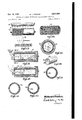
- Figure 11 is a perspective view of a portion of the completed tubing.
- Figure 12 illustrates a of a metal tube which is to serve as a liner for the completed tubing, the outer surface of the metal tube being roughened to cause the subsequently built-up wall structure to adhere thereto.
- Figure 13 is an elevational view, partly broken away, showing the metal tube with the reinforced plastic covering.
- Figure 14 is an enlarged transverse section of the article shown in Figure 13.
- Figure 15 illustrates a completely formed tube of thermoplastic material adapted to serve as a liner for the subsequently built-up wall produced according to my invention.
- Figure 16 shows the tube of Figure 15 with a solid mandrel inserted therein to reinforce the plastic tube during subsequent operations.
- Figure 17 illustrates the tube of Figure 16 with a reinforced plastic covering thereon which mandrel in the form has been built-up according to my invention and shows the mandrel being. removed.
- Figure 18. is: an. enlarged. transverse sectional view through an. article of the type shown in Figure 17'.
- Figure 19 illustrates. another method of form. ing a reinforced tube, the tube comprising a plastic liner bonded to an outer reinforced plastic wall structure built-up according to. my invention.
- Figure 20 is an enlarged transverse sectional view through. an article formed as illustrated in. Figure 19.
- Figure 21 is a view showing how a reinforcing mat may be convolutely wound on a mandrel previously coated with. the uncured resin.
- Figure 22 is a sectional view along line 22-22 of. Figure 21 illustrating how the uncured resin coating on. the mandrel. is forced out. through the mat.
- Figure. 23 is a view" illustrating how a strand of reinforcing may e wound on the mandrel with. the covering built-up as in Figures. 21 and 22.
- Figure 24 is .a perspective view of a. section. of tubing produceclaccording to Figures 21,. 22. and 2.3.
- Figure 25- illustrates how a preform. of reinforcement may be formed for use in the centrifugal form of my method of producing thetubing.
- Figure 26 is a perspective view of the preform.
- Figure 27 illustrates thev preform. in the: mold with resin. being supplied. to the. interior thereof.
- Figure 28 is a transverse sectional view taken along line 2828 of Figure 27.
- Figure, 29 is a perspective view of a portion of the article which has been produced by the centrifugal method.
- Figure 30 is a view similar to Figure 27 but illustrating how the built-up plastic tubing may be provided. with a previously formed; tubular cover.
- Figure 31 is an end view illustrating the article produced according to Figure 30 with a metal cover.
- Figure 32 is a similar view but. showing the article with a plastic cover.
- Figure 33 is a similar view but showing the article with a diiferent arrangement of plastic cover.
- Mandrel l which is mounted for rotation on a suitable spindle lathe 2 or other suitable apparatus for rotating the mandrel.
- the mandrel I may be either hollow or solid and may be formed of metal or other suitable material which will not adhere to the built-up reinforced plastic wall which will be formed thereon subsequently or which maybe lubricated to prevent such adherence.
- the reinforcement may be any suitable material in the form of a strand or narrow band.
- the reinforcement is illustrated as a strand 5 which is unwound from a spool 6.
- the strand 5 is helically wound on the resin-coated. mandrel, the spool 6 being suitably movedaxial-- 1y of the mandrel so that the mandrel will be traversed several times in winding the strand thereon.
- any suitable selected lead may be used in obtaining the desired angular relationship of the reinforcing strand relative to the axis of the mandrel.
- the lead or angular relationship employed will depend somewhat upon the purpose for which the tubeis to be used. Obviously, the lead may be such that maximum bursting, strength or maximum bending strength is obtained in the tube.
- the resin is initially applied to the mandrel. preferably in a thickness of about TLG' inch.
- the mandrel. may be rotated at such a speed that the resin will not be thrown off to any considerable extent.- This will depend somewhat upon the diameter of the mandrel and the viscosity of the resin.
- the strand 5 may be composed of filaments. to which have been given little or no twist, or it may be. a band or strip of strands to each of which have been added little or no twist.
- resin forces between the filaments of the strands, forcing air ahead of it.
- the resin will also be forced outwardly-around the strands.
- the viscosity of the resin should be such as to permit this.
- additional resin is preferably added, for example by the trough 3, to keep the thickness of the resin outside the reinforcement substantially the same as the thick-- ness of the original coating.
- the flowable resin is forced outwardly through the strand and between the adjacent convolutions of the reinforcement.
- the air'in. the resin is forced ahead of the strand and outwardly through the resin. Consequently, any air bubbles will be formed at the extreme outer surface of the reinforced coatingand will subsequently burst or be wiped off.
- the next step is to apply suitable diluent on the outer surface of the.
- a polyester res-in for the coating and if this type of resin is employed, I prefer to use monomeric styrene as the thinner. I preferably use monomeric styrene although I may use d1- allyl phthalate or divinyl benzene in ethyl vinyl benzene. Not much of the thinned resin itself remains with the resin reinforcement built-up wall, but since monomeric styrene and the other diluents mentioned copolymerize with the resin, no special effort is required to remove this styrene-containin resin. In some cases, if a sufficiently thin resin is applied to the mandrel, no bubbles are formed at the surface of the built-up coating and it is not necessary to use a thinner for the resin.
- Winding the reinforcement strand on the mandrel develops considerable pressure and, therefore, effectively forces the air outwardly through the resin coating.
- the mandrel if hollow, should be of sufficient wall strength or be strengthened with a plug to resist this pressure.
- the viscosity of the resin depends somewhat upon the size of the mandrel and the speed at which it is rotated and the lead used in winding the strand on the mandrel, as previously indicated, is dependent somewhat upon the purpose for which the tubing is to be used. For example, a high pressure tubing would have the reinforcement essentially circumferentially while a low pressure tube, carrying a heavy liquid and supported only at long intervals, could have the reinforcement extending essentially longitudinally. I have used angles of lead of from one degree to sixty degrees with success.
- any suitable traversing mechanism may be used for applying the strand of reinforcement to the mandrel.
- I have illustrated that the mandrel is rotated. However, it is possible to hold the mandrel stationary and to rotate a reinforcement-carrying head about the mandrel in order to wind the reinforcement thereon. This latter procedure would be desirable if the mandrel is a tube which it is desirable to heat internally by steam or other heating medium to cure or partially cure the resin as the reinforcement is bein wound thereon or after it is completely wound thereon.
- the build-up of resin and reinforcement may, if desired, be surfaced with a convolute winding of cellophane, and subsequently cured by the application of heat. Or, the resin may be cured with no protective covering if the mandrel is continuously rotated to counteract the tendency of the resin to flow downward during early stages of cure.
- any other suitable material can be employed since the purpose of the strip is to prevent gravitation of the' resin during the curing operation.
- the mandrel wrapped in this manner may be positioned in an oven 9, as shown in Figure 9, where it may :be subjected to a heating operation at a suitable temperature and for a suitable period of time to completely cure the resin.
- a suitable temperature for example, if a polyester resin is used, I may employ a temperature of from 200 F. to 275 F. for periods ranging from 5 minutes to 1 hour.
- the cellophane strip is now removed from the article and the mandrel I may also be removed.
- the resulting tubing is illustrated in Figure 11.
- This tubing will consist of a body I0 of cured resin having reinforcement H embedded therein in the form of file.- ments which are spaced from each other in all directions and arranged in an interwoven pattern, as distinguished from definite layers which tend to separate.
- the mandrel may be desirable to retain the mandrel within the reinforced plastic tube in some instances.
- the surface thereof is roughened suitably, as indicated at l3.
- the reinforced plastic covering I4 is formed in exactly the same manner as before.
- the reinforced plastic covering I4 is formed in exactly the same manner as before.
- r mandrel is not removed from the completed article but, in fact, forms a part of the completed article.
- Such article is illustrated in Figure 14 and will include the outer reinforced plastic covering I4, which is equivalent to the article of Figure 11, in covering relationship to the interior liner or metal tube [2.
- thermoplastic tubing of various types for conducting certain chemicals due to the high chemical resistance of such material. They may also have electrical uses. However, this type of tubing does not have the necessary structural strength particularly at elevated temperatures.
- Such tubing can be reinforced according to my invention.
- a tube l5 of thermoplastic resin as shown in Figure 15, may receive a wood dowel or mandrel IE to maintain its shape during the subsequent steps of my method.
- a built-up reinforced plastic covering 11 is formed on the tube I5 in exactly the same manner as the covering [4 of Figure 14 is formed.
- the mandrel l 6 is removed and the resulting article or tubing will consist of the inner liner l5 of a thermoplastic material reinforced by an outer built-up reinforced layer H.
- FIGs 19 and 20 I have illustrated a somewhat similar process of forming reinforced plastic tubing with the exception that the two layers, similar to the layers 15 and I! of Figure 18, are caused to chemically react with each other to produce a completely welded joint I8, as shown in Figure 20.
- I start with a tube 19 which is formed by applying a coating of a suitable resin, such as a polyester resin, and then partially polymerize such resin by the use of infra-red heating lamps 20 or by any other suitable means.
- the polyester resin coating is jelled by heat from the lamps and at this time polymerization is substantially 15 to 20 per cent complete.
- a reinforced plastic covering 21 is then built-up in the manner previously described on the partially cured coating 19.
- the finished article as shown in Figure 20, will consist of a lining IQ of a polyester resin and a covering 2
- FIGs 21 to 23 I illustrate another method of making reinforced plastic tubing according to my invention.
- This reinforcement may be a loosely woven mat 22 of glass fibers.
- This mat may be formed of glass fibers bonded with :a resin which provides little tensile strength. Consequently, I wind this mat convolutely on the mandrel which has been coated with resin in the manner previously described As the mat is wound on the mandrel, the resin is forced outwardly through the fiber bundles and through the interstices thereof, forcing the air ahead of the resin so as to force any air bubbles to the surface of the resin coating. Additional resin may be added to the mandrel during the winding operation. As indicated in Figure 22, the mat will be embedded .in the resin and will be completely covered by a coating 23 of the resin.
- next step is to wind a strand a of suitable material over the resin embedded mat in the same manner as discussed with reference to Figure 4.
- the built-up tubing may then be treated by curing in the manner previously described and the article of Figure 24 will result.
- This article will consist of the filaments of the mat 22 and the overlying reinforcing 5a both of which are embedded in the resin material 23.
- the mandrel-winding form of my method described above will produce tubing with an extremely smooth inner surface which will be next to the mandrel during the formation thereof.
- the centrifugal form of my method, now to be described, will produce tubing with an extremely smooth outer surface.
- a typical polyester resin in monomeric form has a specific gravity of 1.13.
- the same resin cured has a specific gravity of 1.22.
- Bulk glass of the composition used to make glass fibers has a specific gravity of 2.54.
- the specific gravity is somewhat lower, possibly as low as 2.4.
- the individual filaments are not used alone, but rather as bundles. Some air is trapped between the individual filaments so that the bundles have an apparent specific gravity less than 2.4. The presence of twist in these bundles (i. e. yarn) reduces the voids between the filaments and increases the apparent specific gravity.
- a pretreatment may sometimes be used to advan- 10 tage to increase the apparent specific gravity to a usable value.
- Styrene is a liquid of low viscosity and low surface tension. It effectively enters these bundles of glass fibers, wetting out these glass rods, and by displacing the-air in the fiber bundles increases the apparent specific gravity. The small quantity of styrene remaining with and in the fiber bundles is not harmful as it co-polymerizes with the polyester 'resin.
- Minimum angular velocity is that above which this rolling does not occur. This appears to be about to 300 R. P. M. for a 3 tube. Higher speeds would be used to more effectively force the reinforcement toward and to displace air near the outer surface with resin.
- This method provides a tube-whose outer surface fairly well duplicates the inner surface of the mold, while variations in wall thickness show up as irregularities on the inner surface.
- the reinforcement may be yarn, which may be preformed by winding on a mandrel with a suitable traverse mechanism to provide the desired angular fiber distribution and with a suitable build-up to provide the desired wall thickness.
- a temporary adhesive such as is provided by using small quantities of butyl methacrylate in solvent, will provide sufficient strength to remove the preform from the mandrel'and place it in the mold.
- the outside of the build-up is made slightly under the I. D. of the mold. As the preform rotates, the butyl methacrylate is softened by the polyester resin. The preform expands against the mold by reducing slightly the angularity of the yarn.
- the reinforcement may be in the form of- This, too, may be preformed by wrap-- fabric. ping on a mandrel, and again small quantities of a temporary adhesive, such as butyl methacrylate, may be used to bind the preform for transferral to the mold.
- a temporary adhesive such as butyl methacrylate
- Glass fiber mat may be wrapped on a mandrel or it may be placed directly inside the mold.
- each ply should be slightly longer than the length required for one revolution.
- Some of the mats have a low apparent specific gravity, and the necessary pretreating may be done in the mold by adding styrene and rotating. After pretreating, the excess styrene may be drained off through a tap in an end plug or cap. The speed may be resumed and the polyester resin added.
- a cylindrical preform of glass fibers may be made with equipment similar to that used to preform rabbit fur for hats. Glass fibers, dispersed in air, would be drawn or allowed to settle down into a two-piece, perforated preforming mold. Suction outward through the perforated sides hold the fibers against the preforming mold. Distribution of the fibers along the perforated surface is influenced by the air flow through the screen at any point. This in turn, is influenced by the amount of perforation and by the build-up of fibers already accumulated. A temporary adhesive is added to facilitate transferral to the mold, where it is densified with styrene and handled much as the mat preforms.
- the essentials for molding by this method are a tube and a mechanism for rotating it.
- One end may be capped or plugged completely, care being taken when a cap is used that there is no overhang or plastic between the cap and the end of the tube as much as overhang would complicate removal of the cured reinforced plastic part from the mold.
- the other end should be partially open, preferably an annular cap which seals the outer area of the tube. After the reinforcement is placed in the mold, the cap is placed on the remaining open end, and with the assembly rotating, resin is added through a hol in the cap.
- FIG 25 I illustrate one way in which a preform may be produced for use in the centrifugal form of my method.
- the preform (Figure 26) may be of tubular or other form and may be produced by winding the strand 26 on a mandrel 21 and at the same time dropping a small amount of temporary adhesive thereon from a trough 28.
- the preform 25 will then be placed in the mold 29 which is shown in Figure 27.
- One end of this mold will be closed by a removable cap 30 which has a central inlet opening 3
- the preform 25 is placed in the mold 29 and the mold is rotated at the same time that resin is supplied thereto.
- the resin will be forced out through the preform, as shown in Figure 28, and the air will be forced inwardly and be eliminated.
- the tube 32 may be removed from the mold and will appear as in Figure 29, having an extremely smooth outer surface 33 and a relatively smooth inner surface 34 at which surface the air is eliminated.
- a metal tube 35 may first be placed in the mold and then the preform will be inserted in the tube 35.
- the tube 35 preferably will have a rough inner surface and the built-up tube will adhere thereto.
- the resulting article as shown in Figure 31, will comprise the outer metal cover 35 and the inner built-up tube 32a.
- the cover may be metal, it may be a previously formed tube 35a of thermoplastic resin as shown in Figure 32, similar to tube I5 of Figure 18. Or it may be a partially polymerized resin tube 352), shown in Figure 33, which is chemically bonded to the built-up tube 32b.
- the tube 35b will be like the tubular liner 19 of Figure 20.
- the reinforcement is in the form of filaments embedded in the plastic material and spaced from each other in all directions.
- the filaments are not exposed at either surface of the wall of the article but each of said surfaces is a continuous smooth coating of plastic.
- the article is so formed that it is non-porous and of high structural strength.
- the method which I provide for making this article is very simple and is of such a nature that the reinforcement is combined with the resin without trapping air in the built-up wall. Furthermore, the method is such that the filament is incorporated with the resin in the built-up wall structure in the form of an interweaving pattern or mat of random fiber orientation which eliminates layer orientation.
- the method of forming a hollow plastic article comprising coating a support with an uncured resin in fiowable condition, applying reinforcement in the form of filaments to the coated support and spacing the filaments from each other sufficiently so that as they are applied to the support the resin of the coating will seep out through the spaces between the filaments and force the air ahead of it, and then curing the resin of the article so formed.
- the method of forming tubing which comprises coating a mandrel with an uncured resin which is in fiowable condition, winding reinforcement in the form of filaments on the coated mandrel and spacing the filaments from each other sufiiciently so that as the reinforcement is wound on the mandrel the resin of the coating will seep out through the spaces between the filaments and force the air ahead of it, and then curing the resin of the tube so formed.
- mandrel is in the form of a metal tube upon which the tubing is formed and which remains within the tubing as a reinforcement therefor.
- a method according to claim 3 wherein a tube of thermoplastic material is applied to the mandrel and is partially polymerized and then the tubing is built-up on the mandreL-the partially polymerized tube and the built-up tubing then being completely polymerized during the curing operation to form a unitary structure.
Description
Oct 1952 R. J. FRANCIS 58 METHODS OF FORMING REINFORCED HOLLOW PLASTIC ARTICLES Filed June 5, 1948 3 Sheets-Sheet l IN V EN TOR.
FicbardJ-fivncii.
BY army; 7y- +4A AITOAWEYS R. J. FRANCIS 2,614,058
METHODS OF FORMING REINFORCED HOLLOW PLASTIC ARTICLES Oct. 14, 1952 3 Sheets-Sheet 2 Filed June 3, 1948 IIIIVIIIIIIIIIIIIIIIIII:
INVENTOR. icltatd-Lfiuncis.
' BY w MWJM J 71 12 ATTORNEYS Oct. 14, 1952 R. J. FRANCIS 2,614,058
METHODS OF FORMING REINFORCED HOLLOW PLASTIC ARTICLES Filed June 3, 1948 I5 Sheets-Sheet 3 INVENTOR. fluflarddfi'allcls.
BY a ed; W W
Arrow/gm 9' mm "m" Q. 0.0m... WM MM Illlllllllllllllllllllllllllzll- W: WW. Iii-0,030:
\lllllllllllllllllll I I o H 0 Patented Oct. 14, 1952 UNITED STATES PATENT OFFICE METHODS OF FORMING REINFORCED HOLLOW PLASTIC ARTICLES 11 Claims.
My invention relates to methods of forming reinforced hollow plastic articles. More specifically, it relates to reinforced plastic tubing and method of making the same, although it is not limited to tubing.
Reinforced plastic tubing is now being made and used. However, this prior art plastic tubing has certain undesirable characteristics. Prior art plastic tubing does not have suflicient structural strength for all purposes and quite often is porous which makes it unsuitable for certain uses such as for conducting fiuids and especially fluids under pressure. The most common type of reinforced plastic tubing now in use is made from a suitable resin, such as a polyester resin, reinforced with a cloth formed of glass yarn. The resin is applied to the cloth by first passing the cloth through the uncured resin in liquid form. To produce the tubing, the cloth is convolutely wound on a suitable mandrel in overlapping layers to build up a wall structure. After the tubing is formed in this manner, it is subjected to elevated temperatures which cure the resin. In winding the plastic-coated cloth on the mandrel, air is invariably trapped in the reinforcement as it is built up into a wall structure. This results in the formation of cells or holes in the wall during the forming and curing operations, thereby decreasing the strength of the final tubing and sometimes making it porous, so that the tubing will not be suitable for all uses. Also, because the cloth type reinforcement is used, it is well oriented into definite layers and is, therefore, susceptible to delamination.
Cotton fabric and paper have been used for years to reinforce tubes of phenolic resins. However, here again the reinforcement is first treated with the resin after which the reinforcement is convolutely wound on a mandrel to form a laminated wall structure. This structure has all of the disadvantages pointed out above in connection with the glass cloth reinforced tubing.
One of the objects of my invention is to provide reinforced plastic tubing which is so formed that it will be non-porous and of high structural strength.
Another object of my invention is to provide reinforced plastic tubing wherein the wall of the tubing is composed of reinforcing filaments which are embedded in the plastic material in such a manner that both the inside and, outside of the tubing has a relatively smooth and con-v tinuous plastic surface which is non-porous.
Another object of my invention is to provide plastic tubing of the type indicated in the preterial.
ceding paragraph of such a nature that the re-- inforcement contained within the plastic material is not oriented into definite layers which tend to separate, but, on the other hand, is arranged in an interwoven'pattern so that the various filaments are separated from each other in all directions by the plastic material and there are not definite layers which tend to separate.
Still another object of my invention is to provide a simple, effective and economical method for making reinforced plastic tubing of the type indicated above, such method being adaptable to large scale commercial production of the tubing.
A further object of my invention is to provide a method of forming reinforced plastic tubing which is of such a nature that the reinforcement may be incorporated with the resin in the built-up wall structure in such a manner as to preclude the trapping of air therein and which, consequently, results in the production of tubing free of porosity which promotes leakage and stress concentrations.
An additional object of my invention is to provide a method of forming reinforced plastic tubing wherein the reinforcement in the form of filaments is incorporated with the resin in a built-up wall structure in the form of an interweaving pattern or mat of random fiber orientation thereby resulting in the elimination of layer orientation and, consequently, eliminating the tendency towards delamination.
fVarious other objects will be apparent hereina ter.
The tubing or other hollow article of my invention, as previously indicated, is composed of plastic reinforced with filaments of suitable ma- I have found that polyester resins are the most suitable for use in making my article and I prefer to use glass yarns as the filament. However, although I prefer to use unsaturated polyester resins, I may employ other polymerizing resins, such as polyethylene or the'copolymer of vinylidine chloride and vinyl chloride. Instead of using glass yarns as the filaments, I may employ cotton yarn, wool yarn, thin metal wire, or any other suitable filament material. However. this filament material should be sufiiciently pliable that it can be traversed on a mandrel in'an interweaving pattern or be formed into a mat composed of spaced loosely-related fibers.
The tubing of my invention is produced by a method which in general comprises building up gradually the tubing wall by using a suitable reinforcement and resin of the type indicated. As
the wall of the tubing is being built-up, the uncured liquid resin is forced through and around the reinforcement material, forcing air towards a surface of the tubing, until sufficient wall structure has been built-up, at which time all of the air will have been removed or will appear as bubbles on the tubing surface which can then be removed by breaking so as to eliminate substantially all air.
In producing the tubing according to one form of my process, a mandrel is selected and is completely covered with a coating of the resin material to be used in forming the article. This material is applied to the mandrel in the form of an uncured liquid which will adhere to the mandrel in the form of a tacky coating or film which will completely cover the mandrel in considerable thickness. The filament reinforcing material is then applied to the mandrel in the form of a fine strand or band of fibers or in the form of a loose mat of fibers which is wound on the plastic-coated mandrel. If the reinforcing is applied as a fine strand or band, it is wound helically on the mandrel, the mandrel being traversed a number of times but a sufi'icient lead being used to ensure that the adjacent convolutions of strand or band are spaced from each other. On the other hand, if the reinforcing is applied as a loosely-Woven mat of fibers, it is convolutely wound on the mandrel. In either case, the individual filaments of the reinforcing material are spaced apart sufhciently to permit the plastic material, which coats the mandrel, to seep or ooze out through the interstices between the filaments, forcing all air ahead of it and eventually emerging to the outer surface of the wall being built-up and forming a continuous coating'of resin on such outer surface. It will be apparent that as the reinforcing material is wound on the mandrel and the plastic is squeezed through the interstices, all air will be forced ahead of the resin material. Thus, a wall structure will be built-up which will be non-porous and free of air cells.
After the wall structure of the tubing or other hollow article is built-up in the manner indicated above, the mandrel may or may not be removed. In some instances, it may be desirable to use a hollow mandrel which will not be removed and will serve as a reinforcing liner. However, if the built-up tubing is removed from the mandrel, it will be apparent that there will also be a continuous coating of resin on the inner surface of the tubing.
According to another form of my process the tubing may be built up by a centrifugal method. With this method, a preform of filaments of suitable reinforcing material is first produced. This preform will be of suitable shape, for example, tubular. The preform is then placed in a suitable mold, for example, a metal tube which is heated. Then the mold is rotated at moderately high speeds and the resin is supplied to the interior thereof. Centrifugal force created by rotation of the mold will force the uncured resin outwardly through and around the strands of the reinforcement preform. This will cause the air to be forced or worked inwardly to the inner surface of the tube being built-up where it will be eliminated. The tubing is then removed fromthe mold and will have an extremely smooth outer surface and a relatively smooth inner surface, both comprising continuous coatings of resin.
The tubing built-up by either form of my method is next subjected to a suitable drying or heating operation which causes curing of the resin. The resulting article will be composed of a suitable wall thickness of completely cured resin having filaments of suitable reinforcement embedded therein and arranged either in an interwoven pattern of strands of reinforcement or as a mat composed of random oriented fibers. In either case, the filaments will be separated from each other in all directions with cured resin material being disposed therebetween and producing an adherent mass. The mandrel-winding method is preferred for forming tubing with an extremely smooth inner surface While the centrifugal method is preferred for forming tubes with an extremely smooth outer surface.
In the accompanying drawings, I have illustrated diagrammatically the manner in which my method may be performed and I have also illustrated the resulting products of such method. In these drawings:
Figure 1 illustrates a mandrel upon which tubing may be formed according to my invention, the mandrel being mounted for rotation.
Figure 2 is a view showing how the uncured resin in liquid form may be applied to the mandrel.
Figure 3 is a transverse section taken along line 3-3 of Figure 2 through the mandrel showing the coating or resin carried thereby.
Figure 4 is a view showing how the reinforcing strand is spirally wound on the rotating mandrel.
Figure 5 is a longitudinal sectional view taken through the mandrel of Figure 4 along line 55 illustrating how the resin is forced out between the convolutions of reinforcement as the reinforcement is wound on the mandrel.
Figure 6 illustrates how a solvent may be applied to the outer surface of the partially completed article on the mandrel to ensure that a continuous smooth film or coating of resin is produced on the outermost surface of such article.
Figure 7 is a view similar to Figure 5 but illustrating the condition of the partially completed article after the treatment indicated in Figure 6.
Figure 8 illustrates how a protecting covering in the form of a band helically wound on the outer surface of the article may be applied to such article preparatory to curing the article.
Figure 9 illustrates the curing operation.
Figure 10 illustrates the completed cured article and indicates that the mandrel is removed therefrom.
Figure 11 is a perspective view of a portion of the completed tubing.
Figure 12 illustrates a of a metal tube which is to serve as a liner for the completed tubing, the outer surface of the metal tube being roughened to cause the subsequently built-up wall structure to adhere thereto.
Figure 13 is an elevational view, partly broken away, showing the metal tube with the reinforced plastic covering.
Figure 14 is an enlarged transverse section of the article shown in Figure 13.
Figure 15 illustrates a completely formed tube of thermoplastic material adapted to serve as a liner for the subsequently built-up wall produced according to my invention.
Figure 16 shows the tube of Figure 15 with a solid mandrel inserted therein to reinforce the plastic tube during subsequent operations.
Figure 17 illustrates the tube of Figure 16 with a reinforced plastic covering thereon which mandrel in the form has been built-up according to my invention and shows the mandrel being. removed.
Figure 18. is: an. enlarged. transverse sectional view through an. article of the type shown in Figure 17'.
Figure 19 illustrates. another method of form. ing a reinforced tube, the tube comprising a plastic liner bonded to an outer reinforced plastic wall structure built-up according to. my invention.
Figure 20 is an enlarged transverse sectional view through. an article formed as illustrated in. Figure 19.
Figure 21 is a view showing how a reinforcing mat may be convolutely wound on a mandrel previously coated with. the uncured resin.
Figure 22 is a sectional view along line 22-22 of. Figure 21 illustrating how the uncured resin coating on. the mandrel. is forced out. through the mat.
Figure. 23 is a view" illustrating how a strand of reinforcing may e wound on the mandrel with. the covering built-up as in Figures. 21 and 22.
Figure 24 is .a perspective view of a. section. of tubing produceclaccording to Figures 21,. 22. and 2.3.
Figure 25- illustrates how a preform. of reinforcement may be formed for use in the centrifugal form of my method of producing thetubing.
Figure 26 is a perspective view of the preform.
Figure 27 illustrates thev preform. in the: mold with resin. being supplied. to the. interior thereof. Figure 28 is a transverse sectional view taken along line 2828 of Figure 27.
Figure, 29 is a perspective view of a portion of the article which has been produced by the centrifugal method.
Figure 30 is a view similar to Figure 27 but illustrating how the built-up plastic tubing may be provided. with a previously formed; tubular cover.
Figure 31 is an end view illustrating the article produced according to Figure 30 with a metal cover.
Figure 32 is a similar view but. showing the article with a plastic cover.
Figure 33 is a similar view but showing the article with a diiferent arrangement of plastic cover.
I have illustrated in the drawings several ways in which my process may be performed. Figures 1 to 24, inclusive, illustrate the mandrel-winding; r
form of my method. while Figures 25 to. 33, inelusive, illustrate the centrifugal form of my method.
In Figure 1, I have illustrated a mandrel l which is mounted for rotation on a suitable spindle lathe 2 or other suitable apparatus for rotating the mandrel. The mandrel I may be either hollow or solid and may be formed of metal or other suitable material which will not adhere to the built-up reinforced plastic wall which will be formed thereon subsequently or which maybe lubricated to prevent such adherence.
As illustrated in Figure 2., the uncured resin,
in liquid form, is applied to the surface. of the This may be accomplished in any mandrel. suitable way but I illustrate a trough 3 with an elongated discharge slot which extends substantially the full length of the mandrel. This trough will contain the uncured resin and it will be allowed. to discharge slowly onto the mandrel while the mandrel is rotated. As. indicated in Figure 3, a substantially continuous. thick coating 4 of the resin will be applied to the mandrel I. This coating will be relatively viscous and tacky so that it will adhere to the mandrel but still will be flowable so that it can be forced outwardly between the reinforcement as His subsequently applied to the mandrel.
The next step is to apply the reinforcement. to the resin-coated mandrel and. this step is. illustrated in Figure 4. As previously indicated, the reinforcement may be any suitable material in the form of a strand or narrow band. In Figure 4, the reinforcement is illustrated asa strand 5 which is unwound from a spool 6. The strand 5 is helically wound on the resin-coated. mandrel, the spool 6 being suitably movedaxial-- 1y of the mandrel so that the mandrel will be traversed several times in winding the strand thereon. In winding the strand on the mandrel, any suitable selected lead may be used in obtaining the desired angular relationship of the reinforcing strand relative to the axis of the mandrel. The lead or angular relationship employed will depend somewhat upon the purpose for which the tubeis to be used. Obviously, the lead may be such that maximum bursting, strength or maximum bending strength is obtained in the tube.
The resin is initially applied to the mandrel. preferably in a thickness of about TLG' inch. In winding the strand 5 on the mandrel, the mandrel. may be rotated at such a speed that the resin will not be thrown off to any considerable extent.- This will depend somewhat upon the diameter of the mandrel and the viscosity of the resin.
The strand 5 may be composed of filaments. to which have been given little or no twist, or it may be. a band or strip of strands to each of which have been added little or no twist. As this is wound on the resin-covered mandrel, resin forces between the filaments of the strands, forcing air ahead of it. Of course, the resin will also be forced outwardly-around the strands. As previously indicated, the viscosity of the resin should be such as to permit this. During the winding of the strand 5 on the mandrel, additional resin is preferably added, for example by the trough 3, to keep the thickness of the resin outside the reinforcement substantially the same as the thick-- ness of the original coating. FOr example, it is preferable to keep a coating of about inch of resin outside the reinforcement. As indicatedin Figure 5, as the strand reinforcement 5 is wound on the mandrel I, the flowable resin is forced outwardly through the strand and between the adjacent convolutions of the reinforcement. As the strand is wound on the mandrel and be comes embedded in the resin coating, the air'in. the resin is forced ahead of the strand and outwardly through the resin. Consequently, any air bubbles will be formed at the extreme outer surface of the reinforced coatingand will subsequently burst or be wiped off. As indicated in Figure 6, the next step is to apply suitable diluent on the outer surface of the.
reinforced resin coating to eliminate any air-bublbles formed during the winding operation and to produce a smooth outer surface. This diluent may be brushed on the rotating mandrel or applied in any other suitable manner. It reduces the viscosity, and possibly the surface tension, or the uncured resin. 'As previously indicated, I
prefer to use a polyester res-in for the coating and if this type of resin is employed, I prefer to use monomeric styrene as the thinner. I preferably use monomeric styrene although I may use d1- allyl phthalate or divinyl benzene in ethyl vinyl benzene. Not much of the thinned resin itself remains with the resin reinforcement built-up wall, but since monomeric styrene and the other diluents mentioned copolymerize with the resin, no special effort is required to remove this styrene-containin resin. In some cases, if a sufficiently thin resin is applied to the mandrel, no bubbles are formed at the surface of the built-up coating and it is not necessary to use a thinner for the resin.
This procedure will result in a non-porous built-up plastic wall of suitable thickness which has an outer continuous coating 1 of resin. For example, I have found that it is possible to make tubing in this manner in built-up wall thicknesses ranging from s; of an inch to inch. However, it is possible to make tubing of greater thicknesses.
Winding the reinforcement strand on the mandrel develops considerable pressure and, therefore, effectively forces the air outwardly through the resin coating. The mandrel, if hollow, should be of sufficient wall strength or be strengthened with a plug to resist this pressure. The viscosity of the resin depends somewhat upon the size of the mandrel and the speed at which it is rotated and the lead used in winding the strand on the mandrel, as previously indicated, is dependent somewhat upon the purpose for which the tubing is to be used. For example, a high pressure tubing would have the reinforcement essentially circumferentially while a low pressure tube, carrying a heavy liquid and supported only at long intervals, could have the reinforcement extending essentially longitudinally. I have used angles of lead of from one degree to sixty degrees with success.
Any suitable traversing mechanism may be used for applying the strand of reinforcement to the mandrel. In Figure 4, I have illustrated that the mandrel is rotated. However, it is possible to hold the mandrel stationary and to rotate a reinforcement-carrying head about the mandrel in order to wind the reinforcement thereon. This latter procedure would be desirable if the mandrel is a tube which it is desirable to heat internally by steam or other heating medium to cure or partially cure the resin as the reinforcement is bein wound thereon or after it is completely wound thereon.
When the reinforced plastic wall has been builtup to the condition illustrated in Figure 7, it is necessary to thoroughly cure the resin of the wall. This may be accomplished in various ways, for example, as mentioned above, by internally heating the mandrel either during or after completion of the winding operation.
The build-up of resin and reinforcement may, if desired, be surfaced with a convolute winding of cellophane, and subsequently cured by the application of heat. Or, the resin may be cured with no protective covering if the mandrel is continuously rotated to counteract the tendency of the resin to flow downward during early stages of cure. I
In Figures 8 and 9, I have illustrated a strip 8 of cellophane or other suitable material helically wound on the partially completed tubing in overlapping convolutions. A slight tension on the cellophane strip will force the excess resin ahead of the strip as it is being wound on the mandrel,
so that most of the excess resin will be removed from the mandrel. Instead of using cellophane strip or tape, any other suitable material can be employed since the purpose of the strip is to prevent gravitation of the' resin during the curing operation. The mandrel wrapped in this manner may be positioned in an oven 9, as shown in Figure 9, where it may :be subjected to a heating operation at a suitable temperature and for a suitable period of time to completely cure the resin. For example, if a polyester resin is used, I may employ a temperature of from 200 F. to 275 F. for periods ranging from 5 minutes to 1 hour.
As indicated in Figure 10, the cellophane strip is now removed from the article and the mandrel I may also be removed. The resulting tubing is illustrated in Figure 11. This tubing will consist of a body I0 of cured resin having reinforcement H embedded therein in the form of file.- ments which are spaced from each other in all directions and arranged in an interwoven pattern, as distinguished from definite layers which tend to separate.
As previously indicated, it may be desirable to retain the mandrel within the reinforced plastic tube in some instances. For example, it may be desirable to apply a built-up reinforced plastic wall as a covering to a metal tube l2 shown in Figure 12. In order to ensure that the built-up covering will adhere to the hollow mandrel or metal tube, the surface thereof is roughened suitably, as indicated at l3. Then the reinforced plastic covering I4 is formed in exactly the same manner as before. However, in this instance, the
r mandrel is not removed from the completed article but, in fact, forms a part of the completed article. Such article is illustrated in Figure 14 and will include the outer reinforced plastic covering I4, which is equivalent to the article of Figure 11, in covering relationship to the interior liner or metal tube [2.
It has been the custom to use thermoplastic tubing of various types for conducting certain chemicals due to the high chemical resistance of such material. They may also have electrical uses. However, this type of tubing does not have the necessary structural strength particularly at elevated temperatures. Such tubing can be reinforced according to my invention. For example, a tube l5 of thermoplastic resin, as shown in Figure 15, may receive a wood dowel or mandrel IE to maintain its shape during the subsequent steps of my method. Then, as shown in Figures 17 and 18, a built-up reinforced plastic covering 11 is formed on the tube I5 in exactly the same manner as the covering [4 of Figure 14 is formed. As shown in Figure 17, the mandrel l 6 is removed and the resulting article or tubing will consist of the inner liner l5 of a thermoplastic material reinforced by an outer built-up reinforced layer H.
In Figures 19 and 20, I have illustrated a somewhat similar process of forming reinforced plastic tubing with the exception that the two layers, similar to the layers 15 and I! of Figure 18, are caused to chemically react with each other to produce a completely welded joint I8, as shown in Figure 20. To accomplish this, as shown in Figure 19, I start with a tube 19 which is formed by applying a coating of a suitable resin, such as a polyester resin, and then partially polymerize such resin by the use of infra-red heating lamps 20 or by any other suitable means. The polyester resin coating is jelled by heat from the lamps and at this time polymerization is substantially 15 to 20 per cent complete. A reinforced plastic covering 21 is then built-up in the manner previously described on the partially cured coating 19. The entire article is then subjected to heat from the infra-red lamps or other suitable means to completely polymerize the lining I9 and the covering 2! to integrally join such layers along the joint l8. Thus, the finished article, as shown in Figure 20, will consist of a lining IQ of a polyester resin and a covering 2| of reinforced polyester resin.
In Figures 21 to 23, I illustrate another method of making reinforced plastic tubing according to my invention. In this instance, I use a different type of reinforcement. This reinforcement may be a loosely woven mat 22 of glass fibers. This mat may be formed of glass fibers bonded with :a resin which provides little tensile strength. Consequently, I wind this mat convolutely on the mandrel which has been coated with resin in the manner previously described As the mat is wound on the mandrel, the resin is forced outwardly through the fiber bundles and through the interstices thereof, forcing the air ahead of the resin so as to force any air bubbles to the surface of the resin coating. Additional resin may be added to the mandrel during the winding operation. As indicated in Figure 22, the mat will be embedded .in the resin and will be completely covered by a coating 23 of the resin. The
next step is to wind a strand a of suitable material over the resin embedded mat in the same manner as discussed with reference to Figure 4. The built-up tubing may then be treated by curing in the manner previously described and the article of Figure 24 will result. This article will consist of the filaments of the mat 22 and the overlying reinforcing 5a both of which are embedded in the resin material 23.
The mandrel-winding form of my method described above, will produce tubing with an extremely smooth inner surface which will be next to the mandrel during the formation thereof. The centrifugal form of my method, now to be described, will produce tubing with an extremely smooth outer surface.
I have made reinforced plastic tubing from polyester resin and glass fibers by placing the resin and a preform of glass fibers in a metal tube and rotating at moderately high speeds while heat is applied to the outer surface of the metal mold.
Success of this centrifugal operation hinges on the fact that the specific gravity of the reinforcement is higher than the specific gravity of the resin. Glass fiber has been used successfully. Wire would also meet the requirements.
A typical polyester resin in monomeric form has a specific gravity of 1.13. The same resin cured has a specific gravity of 1.22. Bulk glass of the composition used to make glass fibers has a specific gravity of 2.54. In fiber form it is believed that the specific gravity is somewhat lower, possibly as low as 2.4. For reinforcing plastics the individual filaments (diameter about 0.003 to 0.004") are not used alone, but rather as bundles. Some air is trapped between the individual filaments so that the bundles have an apparent specific gravity less than 2.4. The presence of twist in these bundles (i. e. yarn) reduces the voids between the filaments and increases the apparent specific gravity.
When the glass fibers are present as loose bundles, with a low apparent specific gravity, a pretreatment may sometimes be used to advan- 10 tage to increase the apparent specific gravity to a usable value. Styrene is a liquid of low viscosity and low surface tension. It effectively enters these bundles of glass fibers, wetting out these glass rods, and by displacing the-air in the fiber bundles increases the apparent specific gravity. The small quantity of styrene remaining with and in the fiber bundles is not harmful as it co-polymerizes with the polyester 'resin.
Angular velocities of 500 to 1,000 B. P. M. .have been used with tubes of 3 diameter. Higher speeds would more effectively force the reinforcement out against the mold and'would more effectively displace air near the outer surface of the reinforced plastic with resin. Higher angular velocities increase the necessity of proper distribution of resin and reinforcement to achieve the proper dynamic balance. At low speeds there is a tendency for the resin and reinforcement to roll in the tube. In some cases the reinforcement may actually roll up into balls. Obviously the reinforcement is not effective if it is rolled up into a series of balls or cylinders around the 1 periphery of the tube. The fibers to be effective should be incorporated in the resin approximately parallel to the outer surface of the tube.
Minimum angular velocity is that above which this rolling does not occur. This appears to be about to 300 R. P. M. for a 3 tube. Higher speeds would be used to more effectively force the reinforcement toward and to displace air near the outer surface with resin.
Because of the loose attachment between the s mold and the resin and reinforcement, starting speeds somewhat slower than that attained with a direct drive are indicated, with 10 to 30 seconds being consumed in getting up to full speed.
This method provides a tube-whose outer surface fairly well duplicates the inner surface of the mold, while variations in wall thickness show up as irregularities on the inner surface.
The reinforcement may be yarn, which may be preformed by winding on a mandrel with a suitable traverse mechanism to provide the desired angular fiber distribution and with a suitable build-up to provide the desired wall thickness. A temporary adhesive, such as is provided by using small quantities of butyl methacrylate in solvent, will provide sufficient strength to remove the preform from the mandrel'and place it in the mold. The outside of the build-up is made slightly under the I. D. of the mold. As the preform rotates, the butyl methacrylate is softened by the polyester resin. The preform expands against the mold by reducing slightly the angularity of the yarn. For this expansion to occur in longer lengths, it is necessary in making the preform to traverse back and forth over a rela-' tively short distance (say 6"), while moving the traversing mechanism along the length of the preforming mandrel (possibly several feet long) If the build-up so requires, the traverse may be moved back and forth several times along the" length of the preforming mandrel.
The reinforcement may be in the form of- This, too, may be preformed by wrap-- fabric. ping on a mandrel, and again small quantities of a temporary adhesive, such as butyl methacrylate, may be used to bind the preform for transferral to the mold. When the wall thickness is such that several layers of fabric are required, it is desirable to have several pieces of fabric,
each piece being no longer than the length needed for one revolution plus a slight lap. This 11 arrangement will allow a slightly undersize preform to expand in the mold.
Glass fiber mat may be wrapped on a mandrel or it may be placed directly inside the mold. Here again if several plies are required to provide the necessary wall thickness, each ply should be slightly longer than the length required for one revolution. Some of the mats have a low apparent specific gravity, and the necessary pretreating may be done in the mold by adding styrene and rotating. After pretreating, the excess styrene may be drained off through a tap in an end plug or cap. The speed may be resumed and the polyester resin added.
A cylindrical preform of glass fibers may be made with equipment similar to that used to preform rabbit fur for hats. Glass fibers, dispersed in air, would be drawn or allowed to settle down into a two-piece, perforated preforming mold. Suction outward through the perforated sides hold the fibers against the preforming mold. Distribution of the fibers along the perforated surface is influenced by the air flow through the screen at any point. This in turn, is influenced by the amount of perforation and by the build-up of fibers already accumulated. A temporary adhesive is added to facilitate transferral to the mold, where it is densified with styrene and handled much as the mat preforms.
The essentials for molding by this method are a tube and a mechanism for rotating it. One end may be capped or plugged completely, care being taken when a cap is used that there is no overhang or plastic between the cap and the end of the tube as much as overhang would complicate removal of the cured reinforced plastic part from the mold. The other end should be partially open, preferably an annular cap which seals the outer area of the tube. After the reinforcement is placed in the mold, the cap is placed on the remaining open end, and with the assembly rotating, resin is added through a hol in the cap.
In Figure 25, I illustrate one way in which a preform may be produced for use in the centrifugal form of my method. The preform (Figure 26) may be of tubular or other form and may be produced by winding the strand 26 on a mandrel 21 and at the same time dropping a small amount of temporary adhesive thereon from a trough 28. The preform 25 will then be placed in the mold 29 which is shown in Figure 27. One end of this mold will be closed by a removable cap 30 which has a central inlet opening 3|. Resin will be supplied to the interior of the mold through a tube 3| a extending inwardly through the opening 3 I.
The preform 25 is placed in the mold 29 and the mold is rotated at the same time that resin is supplied thereto. The resin will be forced out through the preform, as shown in Figure 28, and the air will be forced inwardly and be eliminated. When the wall has been built-up to the desired extent, the tube 32 may be removed from the mold and will appear as in Figure 29, having an extremely smooth outer surface 33 and a relatively smooth inner surface 34 at which surface the air is eliminated.
Sometimes it is desirable to reinforce the builtup tubing with a previously formed tubular cover. For example, as shown in Figure 30, a metal tube 35 may first be placed in the mold and then the preform will be inserted in the tube 35. The tube 35 preferably will have a rough inner surface and the built-up tube will adhere thereto.
12 The resulting article, as shown in Figure 31, will comprise the outer metal cover 35 and the inner built-up tube 32a.
Instead of the cover being metal, it may be a previously formed tube 35a of thermoplastic resin as shown in Figure 32, similar to tube I5 of Figure 18. Or it may be a partially polymerized resin tube 352), shown in Figure 33, which is chemically bonded to the built-up tube 32b. The tube 35b will be like the tubular liner 19 of Figure 20.
It will be apparent from the above description that I have provided a reinforced hollow plastic article having a number of advantages. The reinforcement is in the form of filaments embedded in the plastic material and spaced from each other in all directions. The filaments are not exposed at either surface of the wall of the article but each of said surfaces is a continuous smooth coating of plastic. The article is so formed that it is non-porous and of high structural strength. The method which I provide for making this article is very simple and is of such a nature that the reinforcement is combined with the resin without trapping air in the built-up wall. Furthermore, the method is such that the filament is incorporated with the resin in the built-up wall structure in the form of an interweaving pattern or mat of random fiber orientation which eliminates layer orientation.
Various other advantages will be apparent from the preceding description, the drawings and the following claims.
Having thus described my invention, what I claim is:
1. The method of forming a hollow plastic article comprising coating a support with an uncured resin in fiowable condition, applying reinforcement in the form of filaments to the coated support and spacing the filaments from each other sufficiently so that as they are applied to the support the resin of the coating will seep out through the spaces between the filaments and force the air ahead of it, and then curing the resin of the article so formed.
2. The method of claim 1 which includes coating the support with the uncured resin in sufficient amount to form a continuous coating of resin on the outer surface of the article to completely cover said filaments.
3. The method of forming tubing which comprises coating a mandrel with an uncured resin which is in fiowable condition, winding reinforcement in the form of filaments on the coated mandrel and spacing the filaments from each other sufiiciently so that as the reinforcement is wound on the mandrel the resin of the coating will seep out through the spaces between the filaments and force the air ahead of it, and then curing the resin of the tube so formed.
4. The method of claim 3 which includes coating the mandrel with the uncured resin in sufficient amount to form a continuous coating of resin on the outer surface of the tubing to completely cover said filaments.
5. A method according to claim 4 wherein the tubing is wrapped with a covering before being cured.
6. A method according to claim 3 wherein the mandrel is removed after the curing operation.
7. A method according to claim 3 wherein the mandrel is in the form of a metal tube upon which the tubing is formed and which remains within the tubing as a reinforcement therefor.
8. A method according to claim 3 wherein a 13 tube of thermoplastic material is first applied to the mandrel and then the tubing is formed thereon.
9. A method according to claim 3 wherein a tube of thermoplastic material is applied to the mandrel and is partially polymerized and then the tubing is built-up on the mandreL-the partially polymerized tube and the built-up tubing then being completely polymerized during the curing operation to form a unitary structure.
10. A method according to claim 3 wherein the reinforcement is in the form of a strand helically wound on the mandrel with a sufficient lead to space the convolutions thereof.
11. A method according to claim 3 wherein the reinforcement is applied as a mat of spaced fibers and then as a strand which is wound aroundthe resin-embedded mat with a suflicient lead to space the convolutions thereof.
RICHARD J. FRANCIS.
14 REFERENCES CITED The following references are of record in the file of this patent:
UNITED STATES PATENTS Number Name Date 1,161,756 Wolever Nov. 23, 1915 1,302,744 Whitford May 6, 1919 1,304,694 Marquette May 27, 1919 1,310,715 Rose et a1 July 22, 1919 1,458,931 Frederick June 19,1923 1,668,763 Dickson May 8, 1928 2,029,048 Atwood Jan. 1, 1936 2,255,887 Katz Sept. 16, 1941 2,260,282 Grint Oct. 28, 1941 2,265,226 Clewell et a1 Dec. 9, 1941 2,349,549 Hardman et al. May 23, 1944 2,389,725 Gillis et a1 Nov. 27, 1945 2,455,362 Garrett Dec. 7, 1948 2,467,999 Stephens Apr. 19, 1949 2,470,599 Billmeyer May 17, 1949 2,552,599 Stout May 15, 1951
Claims (1)
1. THE METHOD OF FORMING A HOLLOW PLASTIC ARTICLE COMPRISING COATING A SUPPORT WITH AN UNCURED RESIN IN FLOWABLE CONDITION, APPLYING REINFORCEMENT IN THE FORM OF FILAMENTS TO THE COATED SUPPORT AND SPACING THE FILAMENTS FROM EACH OTHER SUFFICIENTLY SO THAT AS THEY ARE APPLIED TO THE SUPPORT THE RESIN OF THE COATING WILL SEEP OUT THROUGH THE SPACES BETWEEN THE FILAMENTS AND FORCE THE AIR AHEAD OF IT, AND THEN CURING THE RESIN OF THE ARTICLE SO FORMED.
Priority Applications (1)
| Application Number | Priority Date | Filing Date | Title |
|---|---|---|---|
| US30934A US2614058A (en) | 1948-06-03 | 1948-06-03 | Methods of forming reinforced hollow plastic articles |
Applications Claiming Priority (1)
| Application Number | Priority Date | Filing Date | Title |
|---|---|---|---|
| US30934A US2614058A (en) | 1948-06-03 | 1948-06-03 | Methods of forming reinforced hollow plastic articles |
Publications (1)
| Publication Number | Publication Date |
|---|---|
| US2614058A true US2614058A (en) | 1952-10-14 |
Family
ID=21856767
Family Applications (1)
| Application Number | Title | Priority Date | Filing Date |
|---|---|---|---|
| US30934A Expired - Lifetime US2614058A (en) | 1948-06-03 | 1948-06-03 | Methods of forming reinforced hollow plastic articles |
Country Status (1)
| Country | Link |
|---|---|
| US (1) | US2614058A (en) |
Cited By (160)
| Publication number | Priority date | Publication date | Assignee | Title |
|---|---|---|---|---|
| US2695256A (en) * | 1952-11-12 | 1954-11-23 | Carl A Strand | Lightweight bathtub and production thereof |
| US2706497A (en) * | 1952-03-24 | 1955-04-19 | Samuel M Shobert | Fluid conducting plastic impregnated tubing |
| US2731067A (en) * | 1950-11-20 | 1956-01-17 | East Coast Aeronautics Inc | Method and apparatus for making fiber glass pipe |
| US2739917A (en) * | 1953-12-08 | 1956-03-27 | Culligan Inc | Method of making closed fluid pressure containers |
| US2742931A (en) * | 1956-04-24 | De ganahl | ||
| US2747616A (en) * | 1951-07-07 | 1956-05-29 | Ganahl Carl De | Pipe structure |
| US2748830A (en) * | 1953-01-14 | 1956-06-05 | American Fixture Inc | Method and apparatus for making spiral wound synthetic piping and tubing |
| US2760549A (en) * | 1953-01-14 | 1956-08-28 | Korrect Way Corp | Method and apparatus for making highpressure non-metallic tubing |
| US2763003A (en) * | 1953-07-01 | 1956-09-11 | Edward F Harris | Helical antenna construction |
| US2766160A (en) * | 1951-12-16 | 1956-10-09 | Bentov Itzhak | Method of making laminated plastic tubing |
| US2767741A (en) * | 1953-11-23 | 1956-10-23 | Boston Woven Hose & Rubber Co | Forming tube for glass yarn |
| US2773287A (en) * | 1952-07-14 | 1956-12-11 | William H Stout | Method of manufacturing plastic pipe |
| US2783174A (en) * | 1953-05-20 | 1957-02-26 | Minnesota Mining & Mfg | Process for producing fibrous tubes |
| US2785442A (en) * | 1952-01-04 | 1957-03-19 | H D Boggs Company Ltd | Method of making a reinforced hollow cylindrical article |
| US2790464A (en) * | 1953-02-13 | 1957-04-30 | Gustin Bacon Mfg Co | Insulated duct |
| US2791241A (en) * | 1954-07-06 | 1957-05-07 | Smith Corp A O | Fiber reinforced tubular article |
| US2804095A (en) * | 1953-05-04 | 1957-08-27 | Schauenburg Hans Georg | Air ducts for mines and the like |
| US2808097A (en) * | 1954-07-12 | 1957-10-01 | Smith Corp A O | Apparatus for fabricating a fiber reinforced storage structure |
| US2814329A (en) * | 1956-02-01 | 1957-11-26 | Philip N Sitton | Method and apparatus for making the wall portion of a septic tank |
| US2815043A (en) * | 1955-03-29 | 1957-12-03 | Ganahl De | Plastic pipe and method of making same |
| US2822175A (en) * | 1954-11-04 | 1958-02-04 | Woolley Mfg Company | Golf club shaft |
| US2824033A (en) * | 1955-03-01 | 1958-02-18 | Donaldson Chase | Process of manufacturing composite pipe |
| US2843153A (en) * | 1953-08-17 | 1958-07-15 | Richard E Young | Filament wound hollow elements and methods for making same |
| US2845379A (en) * | 1953-09-09 | 1958-07-29 | Chrysler Corp | Method of making a template |
| US2847786A (en) * | 1955-02-07 | 1958-08-19 | Olin Mathieson | Composite firearm barrel comprising glass fibers |
| US2849049A (en) * | 1956-05-16 | 1958-08-26 | Firestone Tire & Rubber Co | Method of forming an endless tire tread and sidewall portion on a carcass band and product thereof |
| US2857932A (en) * | 1955-07-20 | 1958-10-28 | Westinghouse Electric Corp | Composite high strength tubular structure |
| US2859151A (en) * | 1953-09-03 | 1958-11-04 | Reflin Co | Method and apparatus for the centrifugal casting of fiber-reinforced plastic pipe |
| US2858875A (en) * | 1955-07-06 | 1958-11-04 | Aero Nautical Boat Shop Inc | Method and apparatus for producing structural elements of glass fiber reinforced plastics |
| US2862541A (en) * | 1954-04-19 | 1958-12-02 | Fmc Corp | Method of and apparatus for making fiber reinforced plastic pipe |
| US2873226A (en) * | 1954-02-11 | 1959-02-10 | Distillers Co Yeast Ltd | Method of making glass reinforced plastic articles |
| US2928764A (en) * | 1954-01-15 | 1960-03-15 | H D Boggs Company Ltd | Thread casting method |
| US2938566A (en) * | 1956-04-26 | 1960-05-31 | Ohio Commw Eng Co | Apparatus for forming solid structural members of glass fiber reinforced resin |
| US2941915A (en) * | 1954-12-28 | 1960-06-21 | Fred W Manning | Method of making reinforced composite pipe |
| DE1086880B (en) * | 1957-04-06 | 1960-08-11 | Wilhelm Herm Mueller & Co K G | Process for the production of endless flat or toothed belts from meltable plastic with tension inserts |
| US2969840A (en) * | 1957-04-10 | 1961-01-31 | Ranney Method Water Supplies I | Plastic well screen and wells utilizing the screens and method of operation |
| DE1104171B (en) * | 1955-04-09 | 1961-04-06 | Cie De Pont A Mousson S A | Tubular, centrifugally cast body made of heat-hardenable plastic |
| US2990855A (en) * | 1957-11-19 | 1961-07-04 | Clarence L Sipler | Tubular conduits |
| US2995781A (en) * | 1957-11-19 | 1961-08-15 | Clarence L Sipler | Method of making tubular conduits |
| US3000308A (en) * | 1956-03-07 | 1961-09-19 | William E Land | High explosive composition |
| US3002534A (en) * | 1956-10-29 | 1961-10-03 | Reinhold Engineering & Plastic | Reinforced thermoplastics |
| US3006410A (en) * | 1955-08-31 | 1961-10-31 | Ferla Irma | Machines for producing reinforced plastic pipes |
| US3006402A (en) * | 1955-08-31 | 1961-10-31 | Ferla Irma | Apparatus for forming glass reinforced plastic pipe |
| US3022802A (en) * | 1954-11-08 | 1962-02-27 | Harvey M Lewis | Reenforced hollow circular plastic objects |
| DE1125150B (en) * | 1956-09-27 | 1962-03-08 | Mannesmann Ag | Method of lining pipes with layers of plastic |
| DE1125151B (en) * | 1955-04-12 | 1962-03-08 | Christian Stoehr | Hollow bodies, in particular hair curlers, and process for its production |
| US3029475A (en) * | 1958-12-29 | 1962-04-17 | Owens Corning Fiberglass Corp | Method for admixing reinforcing materials and viscous liquid materials |
| US3031099A (en) * | 1953-06-19 | 1962-04-24 | White Sewing Machine Corp | Pressure vessel and method of making the same |
| US3032842A (en) * | 1958-12-15 | 1962-05-08 | Dow Chemical Co | Method of making a fusible metallic core with woven fiber sleeve |
| US3033557A (en) * | 1957-06-19 | 1962-05-08 | Gen Motors Corp | Pneumatic containers and method and apparatus for making the same |
| US3037244A (en) * | 1954-01-21 | 1962-06-05 | H D Boggs Company Ltd | Apparatus for casting of tubular articles |
| US3046170A (en) * | 1954-06-01 | 1962-07-24 | Union Carbide Corp | Laminates of metal plated glass fibers and methods of making same |
| DE1138533B (en) * | 1954-09-28 | 1962-10-25 | Youngstown Sheet And Tube Co | Device for manufacturing a plastic pipe by centrifugal casting |
| US3068134A (en) * | 1954-04-26 | 1962-12-11 | Fmc Corp | Method of making composite plastic pipe of reinforcing glass fibers |
| US3080893A (en) * | 1956-06-29 | 1963-03-12 | Minnesota Mining & Mfg | Reinforced rigid plastic pipe |
| US3082140A (en) * | 1957-08-05 | 1963-03-19 | Pirelli | Method and machine for forming annular bands |
| US3084087A (en) * | 1960-04-27 | 1963-04-02 | Weil | Method of making a frameless lamp shade of resin-impregnated glass fiber |
| US3084088A (en) * | 1958-12-15 | 1963-04-02 | Perma Tubes Ltd | Method of forming a bituminous coated glass fiber pipe |
| US3093532A (en) * | 1958-07-30 | 1963-06-11 | Owens Corning Fiberglass Corp | Apparatus for forming tubular insulating bodies of fibrous structure |
| DE1159698B (en) * | 1960-08-20 | 1963-12-19 | Aerojet General Co | Openwork plastic container, in particular ignition container for liquid or solid rocket propellants and method of manufacturing the container |
| US3115988A (en) * | 1960-01-21 | 1963-12-31 | Studebaker Corp | Laminated wall structure for a nose cone and method of making same |
| DE1161005B (en) * | 1956-11-02 | 1964-01-09 | Polymatic Patentverwertungs G | Process for the production of one-piece, self-contained frames, in particular window or door frames |
| US3121446A (en) * | 1956-02-17 | 1964-02-18 | Patent & Licensing Corp | Nonweeping, noncorrosive pipe |
| US3124001A (en) * | 1964-03-10 | Pressure vessel | ||
| US3125478A (en) * | 1959-10-16 | 1964-03-17 | Method of making plastic tubular members of | |
| US3127910A (en) * | 1954-06-30 | 1964-04-07 | Columbia Products Co | Hollow glass fiber shaft |
| US3143451A (en) * | 1959-10-16 | 1964-08-04 | Babbitt Pipe Company Inc | Method of making a multi-ply plastic tubular article |
| US3150219A (en) * | 1959-08-25 | 1964-09-22 | Schmidt William Karl | Process of making plastic pipes |
| US3152392A (en) * | 1956-05-07 | 1964-10-13 | British Insulated Callenders | Method of attaching fittings to rods or tubes of resin-bonded glass fiber |
| US3154451A (en) * | 1958-12-02 | 1964-10-27 | Angus George Co Ltd | Production of reinforced endless rubber belts or bands |
| DE1183235B (en) * | 1960-03-17 | 1964-12-10 | Jacques Muller | Reinforced pipe and process for its manufacture |
| DE1184938B (en) * | 1956-10-08 | 1965-01-07 | Apollo Carlon Pipe Company | Mandrel for the continuous production of reinforced plastic pipes by winding fiber strips |
| US3177902A (en) * | 1957-12-11 | 1965-04-13 | Rubenstein David | Reinforced pipe and method of making |
| US3190315A (en) * | 1962-09-10 | 1965-06-22 | Goodyear Tire & Rubber | Hose |
| US3194158A (en) * | 1958-03-26 | 1965-07-13 | Jr James T Paul | Explosive weapon casing and method of making same |
| DE1198049B (en) * | 1958-09-15 | 1965-08-05 | Dr Phil Carl Burk | Process for the production of hollow bodies made of plastic and containing reinforcing inserts |
| US3200023A (en) * | 1961-05-09 | 1965-08-10 | Fmc Corp | Method of making a reinforced plastic pipe fitting |
| US3206056A (en) * | 1960-12-09 | 1965-09-14 | Philips Corp | Glass cathode-ray tube for the reproduction of images |
| US3215576A (en) * | 1962-12-11 | 1965-11-02 | Ozark Reconditioning Company | Method of making containers of bonded fiberglass |
| US3221819A (en) * | 1964-05-01 | 1965-12-07 | Richard E Dickinson | Well screen |
| DE1208872B (en) * | 1962-08-22 | 1966-01-13 | Karl Heinz Walter | Device for the continuous production of pipes made of thermoplastics |
| US3250661A (en) * | 1958-02-18 | 1966-05-10 | Avco Mfg Corp | Reinforced material and method of making the same |
| US3283196A (en) * | 1965-02-04 | 1966-11-01 | Westinghouse Electric Corp | Expulsion lightning arrester |
| DE1229548B (en) * | 1964-05-08 | 1966-12-01 | Windmoeller & Hoelscher | Format cylinder for printing machines and process for its production |
| US3289371A (en) * | 1961-09-01 | 1966-12-06 | Owens Corning Fiberglass Corp | Reinforced composites and method for producing the same |
| US3294609A (en) * | 1960-10-17 | 1966-12-27 | Albin M Hancik | Method of making a laminated plastic tube |
| US3298308A (en) * | 1960-11-11 | 1967-01-17 | Aerojet General Co | Composite casing for fragmentationtype explosive weapon and method of forming same |
| US3301727A (en) * | 1964-09-28 | 1967-01-31 | Ohio Brass Co | Method of making hollow insulating booms |
| US3309762A (en) * | 1963-03-08 | 1967-03-21 | Harper Ind Inc | Method for making molded sandwich tubular septic tanks and other molded tubular articles |
| US3335903A (en) * | 1964-02-28 | 1967-08-15 | Standard Oil Co | Plastic tanks |
| US3338271A (en) * | 1963-09-30 | 1967-08-29 | Owens Corning Fiberglass Corp | Impervious tubular wall |
| US3363918A (en) * | 1965-05-27 | 1968-01-16 | Garlock Inc | Reinforced expansion joint |
| US3379591A (en) * | 1961-06-22 | 1968-04-23 | Richard C. Bradley | Filament winding of tubular articles with incorporation of cut lengths of roving during winding |
| DE1275281B (en) * | 1961-12-07 | 1968-08-14 | Thomas Engel | Process and device for the production of molded parts, hollow bodies and containers from thermoplastics |
| US3399092A (en) * | 1964-12-17 | 1968-08-27 | Commercial Filters Corp | Process of making impregnated filter tubes |
| US3412891A (en) * | 1964-08-06 | 1968-11-26 | Owens Corning Fiberglass Corp | Fluid-handling wall structure |
| US3446385A (en) * | 1966-08-05 | 1969-05-27 | Koppers Co Inc | Filament wound reinforced pressure vessel |
| US3449188A (en) * | 1965-08-18 | 1969-06-10 | Ozark Reconditioning Co | Method and apparatus for producing molded hollow articles |
| US3451112A (en) * | 1966-12-07 | 1969-06-24 | Bingham Co Samuel | Rubber covered steel mill rollers |
| US3468346A (en) * | 1966-03-01 | 1969-09-23 | American Cyanamid Co | Pipe fittings having an inner thermoplastic surface and an outer thermoset surface |
| US3514238A (en) * | 1968-09-16 | 1970-05-26 | Black & Decker Mfg Co | Cylinder for fluid pump motor and the like and method of making |
| US3520747A (en) * | 1965-10-29 | 1970-07-14 | Mccreary Tire & Rubber Co | Method of making structural members of layers of corrosion resistant coatings and fibrous material |
| US3533668A (en) * | 1968-02-19 | 1970-10-13 | Plas Steel Products Inc | Reinforced plastic bearing and method for fabricating same |
| US3646651A (en) * | 1965-10-29 | 1972-03-07 | Mccreary Tire & Rubber Co | Abrasion and corrosion resistant composite structural materials and the like |
| US3654002A (en) * | 1968-07-05 | 1972-04-04 | Structural Fibers | Fiber preform and method and apparatus for making same |
| US3661294A (en) * | 1970-08-10 | 1972-05-09 | Owens Corning Fiberglass Corp | Retaining wall for fluids and method for production |
| US3737963A (en) * | 1970-02-07 | 1973-06-12 | Windel Fa Hermann | Roller construction |
| US3742985A (en) * | 1967-01-31 | 1973-07-03 | Chemstress Ind Inc | Reinforced pipe |
| US3794081A (en) * | 1972-05-05 | 1974-02-26 | Smith Inland A O | Fiber reinforced tubular article having abrasion resistant liner |
| DE2422648A1 (en) * | 1973-05-21 | 1974-12-12 | Owens Corning Fiberglass Corp | WALL CONSTRUCTION FROM SEVERAL COMPONENTS |
| US3874972A (en) * | 1967-07-05 | 1975-04-01 | Mancar Trust | Process for the manufacture of improved reinforced glass pipes and other articles |
| US3907004A (en) * | 1972-06-22 | 1975-09-23 | Bridgestone Tire Co Ltd | Light and rigid fiber glass reinforced plastic composite pipes |
| JPS50127972A (en) * | 1974-03-29 | 1975-10-08 | ||
| US3947305A (en) * | 1973-01-22 | 1976-03-30 | The Standard Oil Company | Building a lamination of fiberglass reinforced polyester resin on a rotating mandrel |
| US3948292A (en) * | 1972-12-08 | 1976-04-06 | Hitachi Shipbuilding And Engineering Co., Ltd. | Laminated composite pipe |
| US3965235A (en) * | 1973-01-08 | 1976-06-22 | White Charles S | Method of making a low friction bushing |
| US3973596A (en) * | 1973-08-20 | 1976-08-10 | Walker Grant W | Tubular member and process of forming a tubular member |
| US4075048A (en) * | 1975-10-31 | 1978-02-21 | Owens-Corning Fiberglas Corporation | Method for producing a bead for a pneumatic tire |
| DE2750642A1 (en) * | 1977-05-04 | 1978-11-09 | Gomma Ivg Ind Veneta | METHOD AND DEVICE FOR MANUFACTURING TUBES EXISTING FROM ELASTOMERIC VULCANIZABLE MATERIAL, IN PARTICULAR WITH REINFORCED OR. NOT REINFORCED STRUCTURE |
| US4165765A (en) * | 1976-06-17 | 1979-08-28 | Owens-Corning Fiberglas Corporation | Glass fiber reinforced thermosetting resin pipe wall construction |
| US4205420A (en) * | 1978-03-22 | 1980-06-03 | Repwell Associates, Inc. | Process for making a bent metal tube having a metal-ceramic liner |
| US4243075A (en) * | 1979-02-02 | 1981-01-06 | Clow Corporation | Composite pipe |
| EP0029093A1 (en) * | 1979-11-17 | 1981-05-27 | Felten & Guilleaume Energietechnik GmbH | Fibre-reinforced plastic drive shaft with end parts secured by winding |
| DE3011358A1 (en) * | 1980-03-25 | 1981-10-01 | Audi Nsu Auto Union Ag, 7107 Neckarsulm | Crankshaft esp. for automobile engine - has tubular plastics core fibre reinforced sleeve bearing rings and end cones |
| EP0038555A1 (en) * | 1980-04-21 | 1981-10-28 | Sekisui Kagaku Kogyo Kabushiki Kaisha | Mold for molding a sleeve-equipped reinforced plastic tubular body, and method for handling the mold |
| US4499039A (en) * | 1981-12-29 | 1985-02-12 | Berg Arthur H | Method for making plastic article with fibrous reinforcement |
| US4602722A (en) * | 1985-03-25 | 1986-07-29 | Ives Frank E | Leak-resistant fiberglass tank and method of making the same |
| US4660738A (en) * | 1985-03-25 | 1987-04-28 | Ives Frank E | Leak-resistant fiberglass tank and method of making the same |
| DE3618962A1 (en) * | 1986-06-05 | 1987-12-10 | Adolf Prof Dipl Ing Voss | Process and device for producing high-strength hollow articles using rovings and binders |
| US4772230A (en) * | 1981-12-29 | 1988-09-20 | Cooper Industries, Inc. | Plastic plugs and receptacles reinforced with cured resin coated glass cloth |
| US4983240A (en) * | 1987-09-11 | 1991-01-08 | Kamatics Corporation | Method of making a flanged braided bearing |
| US5218810A (en) * | 1992-02-25 | 1993-06-15 | Hexcel Corporation | Fabric reinforced concrete columns |
| US5320702A (en) * | 1990-07-18 | 1994-06-14 | J.M. Voith Gmbh | Apparatus for manufacturing a press blanket |
| US5334124A (en) * | 1991-02-27 | 1994-08-02 | Nippon Oil Co., Ltd. | Guide rolls |
| US5383994A (en) * | 1990-05-24 | 1995-01-24 | Shea; Lawrence E. | Method for making a double wall fire proof duct |
| US5518564A (en) * | 1992-02-17 | 1996-05-21 | Aerospatiale Societe Nationale Industrielle | Method to embody a complex structural piece by wire or strip contact placing |
| US5609811A (en) * | 1994-04-22 | 1997-03-11 | Tamfelt Corp. | Method for manufacturing an endless reinforced elastomeric press belt |
| US5772938A (en) * | 1996-05-10 | 1998-06-30 | Sharp; Bruce R. | Composite storage tank having double wall characteristics |
| US5897476A (en) * | 1994-08-04 | 1999-04-27 | Valmet Corporation | Variable-crown roll loaded by means of shoes |
| DE19939689A1 (en) * | 1999-08-17 | 2001-05-31 | Siebe Automotive Deutschland Gmbh | Hydraulic line for vehicles, now made more rapidly than ever before |
| DE10014357A1 (en) * | 1999-08-20 | 2001-10-04 | Siebe Automotive Deutschland Gmbh | Hydraulic hose for vehicles, comprises a plastic outer layer, an inner polyamide layer, and an intermediate reinforcing fibre layer. |
| US6458231B1 (en) * | 1999-03-17 | 2002-10-01 | The United States Of America As Represented By The Secretary Of The Air Force | Method of making microtubes with axially variable geometries |
| EP1333052A1 (en) | 2002-02-04 | 2003-08-06 | EMS-Chemie AG | Hydraulic conduits with high barrier amorphous polyamide-clay nanocomposite |
| US20040103976A1 (en) * | 2002-02-19 | 2004-06-03 | Mario Busshoff | Thin-walled reinforced sleeve with integral compressible layer |
| US6793754B1 (en) * | 1999-07-28 | 2004-09-21 | Advanced Materials Corporation | Covered roll having an under-layer formed of resin infused densely packed fibers that provides increased strength and adhesion properties |
| US20070010791A1 (en) * | 2005-07-07 | 2007-01-11 | Bristol-Myers Squibb Company | Valve for inflatable chamber of medical device |
| US20070187415A1 (en) * | 2006-02-14 | 2007-08-16 | D Silva Sean | Glass fiber reinforced gas cylinder |
| EP1942296A1 (en) | 2006-12-22 | 2008-07-09 | Ems-Chemie Ag | Hydraulic line, in particular coupling line and method for its production |
| EP2154401A2 (en) * | 2008-07-17 | 2010-02-17 | Hobas Engineering GmbH | Reinforced plastic fibre pipe |
| US20100294776A1 (en) * | 2009-05-19 | 2010-11-25 | Qiang Liu | High pressure storage device and method |
| WO2013023281A1 (en) * | 2011-08-12 | 2013-02-21 | Joseph Ouellette | Composite article curing |
| WO2013154480A1 (en) * | 2012-04-13 | 2013-10-17 | Atlas Copco Industrial Technique Ab | Failure safety device in a tool holding arm |
| US20130340922A1 (en) * | 2010-08-23 | 2013-12-26 | Hon Hai Precision Industry Co., Ltd. | Method for making carbon nanotube composite hollow structure |
| DE102013003505A1 (en) * | 2013-03-04 | 2014-09-04 | Thyssenkrupp Electrolysis Gmbh | Method for producing a pipe |
| CN104441683A (en) * | 2014-12-12 | 2015-03-25 | 国网辽宁省电力有限公司大连供电公司 | Manufacturing method of insulating cylinder and pipe fitting made from fiber composite material |
| US20150102037A1 (en) * | 2011-12-05 | 2015-04-16 | Francesco Nettis | Single-layer composite pressure vessel |
| US20150136300A1 (en) * | 2012-07-04 | 2015-05-21 | Nomaguchi Incorporation | Method for producing a formed article comprised of a fiber |
| ES2703439A1 (en) * | 2018-12-20 | 2019-03-08 | Univ Madrid Politecnica | METHOD OF REINFORCEMENT OF STRUCTURAL ELEMENTS WITH TEXTILES OF HIGH MECHANICAL PERFORMANCES (Machine-translation by Google Translate, not legally binding) |
| US20190226219A1 (en) * | 2018-01-19 | 2019-07-25 | Titcomb Brothers Manufacturing, Inc. | Loop tie for concrete forming panel systems |
| US11242690B2 (en) * | 2018-01-19 | 2022-02-08 | Titcomb Brothers Manufacturing, Inc. | Loop tie for concrete forming panel systems |
Citations (16)
| Publication number | Priority date | Publication date | Assignee | Title |
|---|---|---|---|---|
| US1161756A (en) * | 1913-08-18 | 1915-11-23 | Ideal Roller Company | Process of manufacturing rollers. |
| US1302744A (en) * | 1917-09-11 | 1919-05-06 | Wilbur W Whitford | Pipe construction. |
| US1304694A (en) * | 1919-05-27 | Process for making strand fabric | ||
| US1310715A (en) * | 1919-07-22 | And gtjstave monrath | ||
| US1458931A (en) * | 1918-11-04 | 1923-06-19 | Westinghouse Electric & Mfg Co | Method of forming annular bodies |
| US1668763A (en) * | 1926-06-19 | 1928-05-08 | Ideal Roller & Mfg Co Inc | Process for making blankets for printing machines |
| US2029048A (en) * | 1934-07-31 | 1936-01-28 | Harry N Atwood | Tubular structural unit and method of making the same |
| US2255887A (en) * | 1939-06-29 | 1941-09-16 | Katz Morris | Paper rod and the method of constructing the same |
| US2260282A (en) * | 1936-10-30 | 1941-10-28 | Grint William Horace | Production of flexible tubes and pipes |
| US2265226A (en) * | 1936-10-17 | 1941-12-09 | Du Pont | Cast resins having integral sheen |
| US2349549A (en) * | 1941-04-24 | 1944-05-23 | Herbert V Hardman | Method of making depolymerized rubber articles |
| US2389725A (en) * | 1941-05-31 | 1945-11-27 | Western Electric Co | Method of and apparatus for applying material to advancing cores |
| US2455362A (en) * | 1947-07-01 | 1948-12-07 | Armstrong Cork Co | Method of making textile fiber drafting aprons |
| US2467999A (en) * | 1944-06-23 | 1949-04-19 | Gustin Bacon Mfg Co | Composite pipe |
| US2470599A (en) * | 1941-07-31 | 1949-05-17 | Armstrong Cork Co | Long draft apron |
| US2552599A (en) * | 1947-01-08 | 1951-05-15 | William H Stout | Conduit pipe |
-
1948
- 1948-06-03 US US30934A patent/US2614058A/en not_active Expired - Lifetime
Patent Citations (16)
| Publication number | Priority date | Publication date | Assignee | Title |
|---|---|---|---|---|
| US1304694A (en) * | 1919-05-27 | Process for making strand fabric | ||
| US1310715A (en) * | 1919-07-22 | And gtjstave monrath | ||
| US1161756A (en) * | 1913-08-18 | 1915-11-23 | Ideal Roller Company | Process of manufacturing rollers. |
| US1302744A (en) * | 1917-09-11 | 1919-05-06 | Wilbur W Whitford | Pipe construction. |
| US1458931A (en) * | 1918-11-04 | 1923-06-19 | Westinghouse Electric & Mfg Co | Method of forming annular bodies |
| US1668763A (en) * | 1926-06-19 | 1928-05-08 | Ideal Roller & Mfg Co Inc | Process for making blankets for printing machines |
| US2029048A (en) * | 1934-07-31 | 1936-01-28 | Harry N Atwood | Tubular structural unit and method of making the same |
| US2265226A (en) * | 1936-10-17 | 1941-12-09 | Du Pont | Cast resins having integral sheen |
| US2260282A (en) * | 1936-10-30 | 1941-10-28 | Grint William Horace | Production of flexible tubes and pipes |
| US2255887A (en) * | 1939-06-29 | 1941-09-16 | Katz Morris | Paper rod and the method of constructing the same |
| US2349549A (en) * | 1941-04-24 | 1944-05-23 | Herbert V Hardman | Method of making depolymerized rubber articles |
| US2389725A (en) * | 1941-05-31 | 1945-11-27 | Western Electric Co | Method of and apparatus for applying material to advancing cores |
| US2470599A (en) * | 1941-07-31 | 1949-05-17 | Armstrong Cork Co | Long draft apron |
| US2467999A (en) * | 1944-06-23 | 1949-04-19 | Gustin Bacon Mfg Co | Composite pipe |
| US2552599A (en) * | 1947-01-08 | 1951-05-15 | William H Stout | Conduit pipe |
| US2455362A (en) * | 1947-07-01 | 1948-12-07 | Armstrong Cork Co | Method of making textile fiber drafting aprons |
Cited By (175)
| Publication number | Priority date | Publication date | Assignee | Title |
|---|---|---|---|---|
| US2742931A (en) * | 1956-04-24 | De ganahl | ||
| US3124001A (en) * | 1964-03-10 | Pressure vessel | ||
| US2731067A (en) * | 1950-11-20 | 1956-01-17 | East Coast Aeronautics Inc | Method and apparatus for making fiber glass pipe |
| US2747616A (en) * | 1951-07-07 | 1956-05-29 | Ganahl Carl De | Pipe structure |
| US2766160A (en) * | 1951-12-16 | 1956-10-09 | Bentov Itzhak | Method of making laminated plastic tubing |
| US2785442A (en) * | 1952-01-04 | 1957-03-19 | H D Boggs Company Ltd | Method of making a reinforced hollow cylindrical article |
| US2706497A (en) * | 1952-03-24 | 1955-04-19 | Samuel M Shobert | Fluid conducting plastic impregnated tubing |
| US2773287A (en) * | 1952-07-14 | 1956-12-11 | William H Stout | Method of manufacturing plastic pipe |
| US2695256A (en) * | 1952-11-12 | 1954-11-23 | Carl A Strand | Lightweight bathtub and production thereof |
| US2760549A (en) * | 1953-01-14 | 1956-08-28 | Korrect Way Corp | Method and apparatus for making highpressure non-metallic tubing |
| US2748830A (en) * | 1953-01-14 | 1956-06-05 | American Fixture Inc | Method and apparatus for making spiral wound synthetic piping and tubing |
| US2790464A (en) * | 1953-02-13 | 1957-04-30 | Gustin Bacon Mfg Co | Insulated duct |
| US2804095A (en) * | 1953-05-04 | 1957-08-27 | Schauenburg Hans Georg | Air ducts for mines and the like |
| US2783174A (en) * | 1953-05-20 | 1957-02-26 | Minnesota Mining & Mfg | Process for producing fibrous tubes |
| US3031099A (en) * | 1953-06-19 | 1962-04-24 | White Sewing Machine Corp | Pressure vessel and method of making the same |
| US2763003A (en) * | 1953-07-01 | 1956-09-11 | Edward F Harris | Helical antenna construction |
| US2843153A (en) * | 1953-08-17 | 1958-07-15 | Richard E Young | Filament wound hollow elements and methods for making same |
| US2859151A (en) * | 1953-09-03 | 1958-11-04 | Reflin Co | Method and apparatus for the centrifugal casting of fiber-reinforced plastic pipe |
| US2845379A (en) * | 1953-09-09 | 1958-07-29 | Chrysler Corp | Method of making a template |
| US2767741A (en) * | 1953-11-23 | 1956-10-23 | Boston Woven Hose & Rubber Co | Forming tube for glass yarn |
| US2739917A (en) * | 1953-12-08 | 1956-03-27 | Culligan Inc | Method of making closed fluid pressure containers |
| US2928764A (en) * | 1954-01-15 | 1960-03-15 | H D Boggs Company Ltd | Thread casting method |
| US3037244A (en) * | 1954-01-21 | 1962-06-05 | H D Boggs Company Ltd | Apparatus for casting of tubular articles |
| US2873226A (en) * | 1954-02-11 | 1959-02-10 | Distillers Co Yeast Ltd | Method of making glass reinforced plastic articles |
| US2862541A (en) * | 1954-04-19 | 1958-12-02 | Fmc Corp | Method of and apparatus for making fiber reinforced plastic pipe |
| US3068134A (en) * | 1954-04-26 | 1962-12-11 | Fmc Corp | Method of making composite plastic pipe of reinforcing glass fibers |
| US3046170A (en) * | 1954-06-01 | 1962-07-24 | Union Carbide Corp | Laminates of metal plated glass fibers and methods of making same |
| US3127910A (en) * | 1954-06-30 | 1964-04-07 | Columbia Products Co | Hollow glass fiber shaft |
| US2791241A (en) * | 1954-07-06 | 1957-05-07 | Smith Corp A O | Fiber reinforced tubular article |
| US2808097A (en) * | 1954-07-12 | 1957-10-01 | Smith Corp A O | Apparatus for fabricating a fiber reinforced storage structure |
| DE1138533B (en) * | 1954-09-28 | 1962-10-25 | Youngstown Sheet And Tube Co | Device for manufacturing a plastic pipe by centrifugal casting |
| US2822175A (en) * | 1954-11-04 | 1958-02-04 | Woolley Mfg Company | Golf club shaft |
| US3022802A (en) * | 1954-11-08 | 1962-02-27 | Harvey M Lewis | Reenforced hollow circular plastic objects |
| US2941915A (en) * | 1954-12-28 | 1960-06-21 | Fred W Manning | Method of making reinforced composite pipe |
| US2847786A (en) * | 1955-02-07 | 1958-08-19 | Olin Mathieson | Composite firearm barrel comprising glass fibers |
| US2824033A (en) * | 1955-03-01 | 1958-02-18 | Donaldson Chase | Process of manufacturing composite pipe |
| US2815043A (en) * | 1955-03-29 | 1957-12-03 | Ganahl De | Plastic pipe and method of making same |
| DE1104171B (en) * | 1955-04-09 | 1961-04-06 | Cie De Pont A Mousson S A | Tubular, centrifugally cast body made of heat-hardenable plastic |
| DE1125151B (en) * | 1955-04-12 | 1962-03-08 | Christian Stoehr | Hollow bodies, in particular hair curlers, and process for its production |
| US2858875A (en) * | 1955-07-06 | 1958-11-04 | Aero Nautical Boat Shop Inc | Method and apparatus for producing structural elements of glass fiber reinforced plastics |
| US2857932A (en) * | 1955-07-20 | 1958-10-28 | Westinghouse Electric Corp | Composite high strength tubular structure |
| US3006410A (en) * | 1955-08-31 | 1961-10-31 | Ferla Irma | Machines for producing reinforced plastic pipes |
| US3006402A (en) * | 1955-08-31 | 1961-10-31 | Ferla Irma | Apparatus for forming glass reinforced plastic pipe |
| US2814329A (en) * | 1956-02-01 | 1957-11-26 | Philip N Sitton | Method and apparatus for making the wall portion of a septic tank |
| US3121446A (en) * | 1956-02-17 | 1964-02-18 | Patent & Licensing Corp | Nonweeping, noncorrosive pipe |
| US3000308A (en) * | 1956-03-07 | 1961-09-19 | William E Land | High explosive composition |
| US2938566A (en) * | 1956-04-26 | 1960-05-31 | Ohio Commw Eng Co | Apparatus for forming solid structural members of glass fiber reinforced resin |
| US3152392A (en) * | 1956-05-07 | 1964-10-13 | British Insulated Callenders | Method of attaching fittings to rods or tubes of resin-bonded glass fiber |
| US2849049A (en) * | 1956-05-16 | 1958-08-26 | Firestone Tire & Rubber Co | Method of forming an endless tire tread and sidewall portion on a carcass band and product thereof |
| US3080893A (en) * | 1956-06-29 | 1963-03-12 | Minnesota Mining & Mfg | Reinforced rigid plastic pipe |
| DE1125150B (en) * | 1956-09-27 | 1962-03-08 | Mannesmann Ag | Method of lining pipes with layers of plastic |
| DE1184938B (en) * | 1956-10-08 | 1965-01-07 | Apollo Carlon Pipe Company | Mandrel for the continuous production of reinforced plastic pipes by winding fiber strips |
| US3002534A (en) * | 1956-10-29 | 1961-10-03 | Reinhold Engineering & Plastic | Reinforced thermoplastics |
| DE1161005B (en) * | 1956-11-02 | 1964-01-09 | Polymatic Patentverwertungs G | Process for the production of one-piece, self-contained frames, in particular window or door frames |
| DE1086880B (en) * | 1957-04-06 | 1960-08-11 | Wilhelm Herm Mueller & Co K G | Process for the production of endless flat or toothed belts from meltable plastic with tension inserts |
| US2969840A (en) * | 1957-04-10 | 1961-01-31 | Ranney Method Water Supplies I | Plastic well screen and wells utilizing the screens and method of operation |
| US3033557A (en) * | 1957-06-19 | 1962-05-08 | Gen Motors Corp | Pneumatic containers and method and apparatus for making the same |
| US3082140A (en) * | 1957-08-05 | 1963-03-19 | Pirelli | Method and machine for forming annular bands |
| US2990855A (en) * | 1957-11-19 | 1961-07-04 | Clarence L Sipler | Tubular conduits |
| US2995781A (en) * | 1957-11-19 | 1961-08-15 | Clarence L Sipler | Method of making tubular conduits |
| US3177902A (en) * | 1957-12-11 | 1965-04-13 | Rubenstein David | Reinforced pipe and method of making |
| US3250661A (en) * | 1958-02-18 | 1966-05-10 | Avco Mfg Corp | Reinforced material and method of making the same |
| US3194158A (en) * | 1958-03-26 | 1965-07-13 | Jr James T Paul | Explosive weapon casing and method of making same |
| US3093532A (en) * | 1958-07-30 | 1963-06-11 | Owens Corning Fiberglass Corp | Apparatus for forming tubular insulating bodies of fibrous structure |
| DE1198049B (en) * | 1958-09-15 | 1965-08-05 | Dr Phil Carl Burk | Process for the production of hollow bodies made of plastic and containing reinforcing inserts |
| US3154451A (en) * | 1958-12-02 | 1964-10-27 | Angus George Co Ltd | Production of reinforced endless rubber belts or bands |
| US3084088A (en) * | 1958-12-15 | 1963-04-02 | Perma Tubes Ltd | Method of forming a bituminous coated glass fiber pipe |
| US3032842A (en) * | 1958-12-15 | 1962-05-08 | Dow Chemical Co | Method of making a fusible metallic core with woven fiber sleeve |
| US3029475A (en) * | 1958-12-29 | 1962-04-17 | Owens Corning Fiberglass Corp | Method for admixing reinforcing materials and viscous liquid materials |
| US3150219A (en) * | 1959-08-25 | 1964-09-22 | Schmidt William Karl | Process of making plastic pipes |
| US3143451A (en) * | 1959-10-16 | 1964-08-04 | Babbitt Pipe Company Inc | Method of making a multi-ply plastic tubular article |
| US3125478A (en) * | 1959-10-16 | 1964-03-17 | Method of making plastic tubular members of | |
| US3115988A (en) * | 1960-01-21 | 1963-12-31 | Studebaker Corp | Laminated wall structure for a nose cone and method of making same |
| DE1183235B (en) * | 1960-03-17 | 1964-12-10 | Jacques Muller | Reinforced pipe and process for its manufacture |
| US3084087A (en) * | 1960-04-27 | 1963-04-02 | Weil | Method of making a frameless lamp shade of resin-impregnated glass fiber |
| DE1159698B (en) * | 1960-08-20 | 1963-12-19 | Aerojet General Co | Openwork plastic container, in particular ignition container for liquid or solid rocket propellants and method of manufacturing the container |
| US3294609A (en) * | 1960-10-17 | 1966-12-27 | Albin M Hancik | Method of making a laminated plastic tube |
| US3298308A (en) * | 1960-11-11 | 1967-01-17 | Aerojet General Co | Composite casing for fragmentationtype explosive weapon and method of forming same |
| US3206056A (en) * | 1960-12-09 | 1965-09-14 | Philips Corp | Glass cathode-ray tube for the reproduction of images |
| US3200023A (en) * | 1961-05-09 | 1965-08-10 | Fmc Corp | Method of making a reinforced plastic pipe fitting |
| US3379591A (en) * | 1961-06-22 | 1968-04-23 | Richard C. Bradley | Filament winding of tubular articles with incorporation of cut lengths of roving during winding |
| US3289371A (en) * | 1961-09-01 | 1966-12-06 | Owens Corning Fiberglass Corp | Reinforced composites and method for producing the same |
| DE1275281B (en) * | 1961-12-07 | 1968-08-14 | Thomas Engel | Process and device for the production of molded parts, hollow bodies and containers from thermoplastics |
| DE1208872B (en) * | 1962-08-22 | 1966-01-13 | Karl Heinz Walter | Device for the continuous production of pipes made of thermoplastics |
| US3190315A (en) * | 1962-09-10 | 1965-06-22 | Goodyear Tire & Rubber | Hose |
| US3215576A (en) * | 1962-12-11 | 1965-11-02 | Ozark Reconditioning Company | Method of making containers of bonded fiberglass |
| US3309762A (en) * | 1963-03-08 | 1967-03-21 | Harper Ind Inc | Method for making molded sandwich tubular septic tanks and other molded tubular articles |
| US3338271A (en) * | 1963-09-30 | 1967-08-29 | Owens Corning Fiberglass Corp | Impervious tubular wall |
| US3335903A (en) * | 1964-02-28 | 1967-08-15 | Standard Oil Co | Plastic tanks |
| US3221819A (en) * | 1964-05-01 | 1965-12-07 | Richard E Dickinson | Well screen |
| DE1229548B (en) * | 1964-05-08 | 1966-12-01 | Windmoeller & Hoelscher | Format cylinder for printing machines and process for its production |
| US3412891A (en) * | 1964-08-06 | 1968-11-26 | Owens Corning Fiberglass Corp | Fluid-handling wall structure |
| US3301727A (en) * | 1964-09-28 | 1967-01-31 | Ohio Brass Co | Method of making hollow insulating booms |
| US3399092A (en) * | 1964-12-17 | 1968-08-27 | Commercial Filters Corp | Process of making impregnated filter tubes |
| US3283196A (en) * | 1965-02-04 | 1966-11-01 | Westinghouse Electric Corp | Expulsion lightning arrester |
| US3363918A (en) * | 1965-05-27 | 1968-01-16 | Garlock Inc | Reinforced expansion joint |
| US3449188A (en) * | 1965-08-18 | 1969-06-10 | Ozark Reconditioning Co | Method and apparatus for producing molded hollow articles |
| US3520747A (en) * | 1965-10-29 | 1970-07-14 | Mccreary Tire & Rubber Co | Method of making structural members of layers of corrosion resistant coatings and fibrous material |
| US3646651A (en) * | 1965-10-29 | 1972-03-07 | Mccreary Tire & Rubber Co | Abrasion and corrosion resistant composite structural materials and the like |
| US3468346A (en) * | 1966-03-01 | 1969-09-23 | American Cyanamid Co | Pipe fittings having an inner thermoplastic surface and an outer thermoset surface |
| US3446385A (en) * | 1966-08-05 | 1969-05-27 | Koppers Co Inc | Filament wound reinforced pressure vessel |
| US3451112A (en) * | 1966-12-07 | 1969-06-24 | Bingham Co Samuel | Rubber covered steel mill rollers |
| US3742985A (en) * | 1967-01-31 | 1973-07-03 | Chemstress Ind Inc | Reinforced pipe |
| US3874972A (en) * | 1967-07-05 | 1975-04-01 | Mancar Trust | Process for the manufacture of improved reinforced glass pipes and other articles |
| US3533668A (en) * | 1968-02-19 | 1970-10-13 | Plas Steel Products Inc | Reinforced plastic bearing and method for fabricating same |
| US3654002A (en) * | 1968-07-05 | 1972-04-04 | Structural Fibers | Fiber preform and method and apparatus for making same |
| US3514238A (en) * | 1968-09-16 | 1970-05-26 | Black & Decker Mfg Co | Cylinder for fluid pump motor and the like and method of making |
| US3737963A (en) * | 1970-02-07 | 1973-06-12 | Windel Fa Hermann | Roller construction |
| US3661294A (en) * | 1970-08-10 | 1972-05-09 | Owens Corning Fiberglass Corp | Retaining wall for fluids and method for production |
| US3794081A (en) * | 1972-05-05 | 1974-02-26 | Smith Inland A O | Fiber reinforced tubular article having abrasion resistant liner |
| US3907004A (en) * | 1972-06-22 | 1975-09-23 | Bridgestone Tire Co Ltd | Light and rigid fiber glass reinforced plastic composite pipes |
| US3948292A (en) * | 1972-12-08 | 1976-04-06 | Hitachi Shipbuilding And Engineering Co., Ltd. | Laminated composite pipe |
| US3965235A (en) * | 1973-01-08 | 1976-06-22 | White Charles S | Method of making a low friction bushing |
| US3947305A (en) * | 1973-01-22 | 1976-03-30 | The Standard Oil Company | Building a lamination of fiberglass reinforced polyester resin on a rotating mandrel |
| DE2422648A1 (en) * | 1973-05-21 | 1974-12-12 | Owens Corning Fiberglass Corp | WALL CONSTRUCTION FROM SEVERAL COMPONENTS |
| US3973596A (en) * | 1973-08-20 | 1976-08-10 | Walker Grant W | Tubular member and process of forming a tubular member |
| JPS50127972A (en) * | 1974-03-29 | 1975-10-08 | ||
| US4075048A (en) * | 1975-10-31 | 1978-02-21 | Owens-Corning Fiberglas Corporation | Method for producing a bead for a pneumatic tire |
| US4165765A (en) * | 1976-06-17 | 1979-08-28 | Owens-Corning Fiberglas Corporation | Glass fiber reinforced thermosetting resin pipe wall construction |
| DE2750642A1 (en) * | 1977-05-04 | 1978-11-09 | Gomma Ivg Ind Veneta | METHOD AND DEVICE FOR MANUFACTURING TUBES EXISTING FROM ELASTOMERIC VULCANIZABLE MATERIAL, IN PARTICULAR WITH REINFORCED OR. NOT REINFORCED STRUCTURE |
| US4205420A (en) * | 1978-03-22 | 1980-06-03 | Repwell Associates, Inc. | Process for making a bent metal tube having a metal-ceramic liner |
| US4243075A (en) * | 1979-02-02 | 1981-01-06 | Clow Corporation | Composite pipe |
| EP0029093A1 (en) * | 1979-11-17 | 1981-05-27 | Felten & Guilleaume Energietechnik GmbH | Fibre-reinforced plastic drive shaft with end parts secured by winding |
| DE3011358A1 (en) * | 1980-03-25 | 1981-10-01 | Audi Nsu Auto Union Ag, 7107 Neckarsulm | Crankshaft esp. for automobile engine - has tubular plastics core fibre reinforced sleeve bearing rings and end cones |
| EP0038555A1 (en) * | 1980-04-21 | 1981-10-28 | Sekisui Kagaku Kogyo Kabushiki Kaisha | Mold for molding a sleeve-equipped reinforced plastic tubular body, and method for handling the mold |
| US4499039A (en) * | 1981-12-29 | 1985-02-12 | Berg Arthur H | Method for making plastic article with fibrous reinforcement |
| US4772230A (en) * | 1981-12-29 | 1988-09-20 | Cooper Industries, Inc. | Plastic plugs and receptacles reinforced with cured resin coated glass cloth |
| US4602722A (en) * | 1985-03-25 | 1986-07-29 | Ives Frank E | Leak-resistant fiberglass tank and method of making the same |
| US4660738A (en) * | 1985-03-25 | 1987-04-28 | Ives Frank E | Leak-resistant fiberglass tank and method of making the same |
| DE3618962A1 (en) * | 1986-06-05 | 1987-12-10 | Adolf Prof Dipl Ing Voss | Process and device for producing high-strength hollow articles using rovings and binders |
| US4983240A (en) * | 1987-09-11 | 1991-01-08 | Kamatics Corporation | Method of making a flanged braided bearing |
| US5383994A (en) * | 1990-05-24 | 1995-01-24 | Shea; Lawrence E. | Method for making a double wall fire proof duct |
| US5320702A (en) * | 1990-07-18 | 1994-06-14 | J.M. Voith Gmbh | Apparatus for manufacturing a press blanket |
| US5334124A (en) * | 1991-02-27 | 1994-08-02 | Nippon Oil Co., Ltd. | Guide rolls |
| US5518564A (en) * | 1992-02-17 | 1996-05-21 | Aerospatiale Societe Nationale Industrielle | Method to embody a complex structural piece by wire or strip contact placing |
| US5218810A (en) * | 1992-02-25 | 1993-06-15 | Hexcel Corporation | Fabric reinforced concrete columns |
| WO1993018245A1 (en) * | 1992-02-25 | 1993-09-16 | Hexcel Corporation | Fabric reinforced concrete columns |
| US5609811A (en) * | 1994-04-22 | 1997-03-11 | Tamfelt Corp. | Method for manufacturing an endless reinforced elastomeric press belt |
| US5897476A (en) * | 1994-08-04 | 1999-04-27 | Valmet Corporation | Variable-crown roll loaded by means of shoes |
| US5772938A (en) * | 1996-05-10 | 1998-06-30 | Sharp; Bruce R. | Composite storage tank having double wall characteristics |
| US6458231B1 (en) * | 1999-03-17 | 2002-10-01 | The United States Of America As Represented By The Secretary Of The Air Force | Method of making microtubes with axially variable geometries |
| US6793754B1 (en) * | 1999-07-28 | 2004-09-21 | Advanced Materials Corporation | Covered roll having an under-layer formed of resin infused densely packed fibers that provides increased strength and adhesion properties |
| DE19939689A1 (en) * | 1999-08-17 | 2001-05-31 | Siebe Automotive Deutschland Gmbh | Hydraulic line for vehicles, now made more rapidly than ever before |
| DE19939689C2 (en) * | 1999-08-17 | 2002-06-06 | Cooper Standard Automotive D | Hydraulic line for motor vehicles |
| DE10014357A1 (en) * | 1999-08-20 | 2001-10-04 | Siebe Automotive Deutschland Gmbh | Hydraulic hose for vehicles, comprises a plastic outer layer, an inner polyamide layer, and an intermediate reinforcing fibre layer. |
| DE10014357C2 (en) * | 1999-08-20 | 2003-10-23 | Cooper Standard Automotive D | Hydraulic line for motor vehicles |
| EP1333052A1 (en) | 2002-02-04 | 2003-08-06 | EMS-Chemie AG | Hydraulic conduits with high barrier amorphous polyamide-clay nanocomposite |
| DE10204395A1 (en) * | 2002-02-04 | 2003-09-18 | Ems Chemie Ag | Hydraulic line and method for manufacturing a hydraulic line |
| DE10204395B4 (en) * | 2002-02-04 | 2004-01-29 | Ems-Chemie Ag | Hydraulic line and method for manufacturing a hydraulic line |
| US20040103976A1 (en) * | 2002-02-19 | 2004-06-03 | Mario Busshoff | Thin-walled reinforced sleeve with integral compressible layer |
| US7285177B2 (en) * | 2002-02-19 | 2007-10-23 | Day International, Inc. | Thin-walled reinforced sleeve with integral compressible layer |
| US20070010791A1 (en) * | 2005-07-07 | 2007-01-11 | Bristol-Myers Squibb Company | Valve for inflatable chamber of medical device |
| US20070187415A1 (en) * | 2006-02-14 | 2007-08-16 | D Silva Sean | Glass fiber reinforced gas cylinder |
| EP1942296A1 (en) | 2006-12-22 | 2008-07-09 | Ems-Chemie Ag | Hydraulic line, in particular coupling line and method for its production |
| EP2154401A2 (en) * | 2008-07-17 | 2010-02-17 | Hobas Engineering GmbH | Reinforced plastic fibre pipe |
| EP2154401A3 (en) * | 2008-07-17 | 2013-10-23 | Hobas Engineering GmbH | Reinforced plastic fibre pipe |
| US20100294776A1 (en) * | 2009-05-19 | 2010-11-25 | Qiang Liu | High pressure storage device and method |
| US8517206B2 (en) * | 2009-05-19 | 2013-08-27 | Quantum Fuel Systems Technologies Worldwide Inc. | High pressure storage vessel |
| US20130340922A1 (en) * | 2010-08-23 | 2013-12-26 | Hon Hai Precision Industry Co., Ltd. | Method for making carbon nanotube composite hollow structure |
| US9242443B2 (en) * | 2010-08-23 | 2016-01-26 | Tsinghua University | Method for making carbon nanotube composite hollow structure |
| WO2013023281A1 (en) * | 2011-08-12 | 2013-02-21 | Joseph Ouellette | Composite article curing |
| US20150102037A1 (en) * | 2011-12-05 | 2015-04-16 | Francesco Nettis | Single-layer composite pressure vessel |
| EP2836337A4 (en) * | 2012-04-13 | 2016-08-31 | Atlas Copco Ind Tech Ab | Failure safety device in a tool holding arm |
| WO2013154480A1 (en) * | 2012-04-13 | 2013-10-17 | Atlas Copco Industrial Technique Ab | Failure safety device in a tool holding arm |
| US20150136300A1 (en) * | 2012-07-04 | 2015-05-21 | Nomaguchi Incorporation | Method for producing a formed article comprised of a fiber |
| US9259881B2 (en) * | 2012-07-04 | 2016-02-16 | Nomaguchi Incorporation | Method for producing a formed article comprised of a fiber |
| DE102013003505A1 (en) * | 2013-03-04 | 2014-09-04 | Thyssenkrupp Electrolysis Gmbh | Method for producing a pipe |
| DE102013003505B4 (en) | 2013-03-04 | 2021-08-12 | Thyssenkrupp Uhde Chlorine Engineers Gmbh | Method of making a pipe |
| CN104441683A (en) * | 2014-12-12 | 2015-03-25 | 国网辽宁省电力有限公司大连供电公司 | Manufacturing method of insulating cylinder and pipe fitting made from fiber composite material |
| US20190226219A1 (en) * | 2018-01-19 | 2019-07-25 | Titcomb Brothers Manufacturing, Inc. | Loop tie for concrete forming panel systems |
| US10907365B2 (en) * | 2018-01-19 | 2021-02-02 | Titcomb Brothers Manufacturing, Inc. | Loop tie for concrete forming panel systems |
| US11242690B2 (en) * | 2018-01-19 | 2022-02-08 | Titcomb Brothers Manufacturing, Inc. | Loop tie for concrete forming panel systems |
| US11572701B2 (en) * | 2018-01-19 | 2023-02-07 | Titcomb Brothers Manufacturing, Inc. | Loop tie for concrete forming panel systems |
| US20230323685A1 (en) * | 2018-01-19 | 2023-10-12 | Titcomb Brothers Manufacturing, Inc. | Loop tie for concrete forming panel systems |
| ES2703439A1 (en) * | 2018-12-20 | 2019-03-08 | Univ Madrid Politecnica | METHOD OF REINFORCEMENT OF STRUCTURAL ELEMENTS WITH TEXTILES OF HIGH MECHANICAL PERFORMANCES (Machine-translation by Google Translate, not legally binding) |
Similar Documents
| Publication | Publication Date | Title |
|---|---|---|
| US2614058A (en) | Methods of forming reinforced hollow plastic articles | |
| US2785442A (en) | Method of making a reinforced hollow cylindrical article | |
| US3579402A (en) | Method and apparatus for producing filament reinforced tubular products on a continuous basis | |
| US2783174A (en) | Process for producing fibrous tubes | |
| US4010054A (en) | Thermoplastic filament winding process | |
| US2969812A (en) | Pipe structure | |
| US2824033A (en) | Process of manufacturing composite pipe | |
| US3470051A (en) | Formation of reinforced plastic rods and tubes | |
| US2979431A (en) | Method and apparatus of producing re-enforced thermoplastic bodies | |
| US2723705A (en) | Method and apparatus for making reinforced plastic laminates | |
| US3769127A (en) | Method and apparatus for producing filament reinforced tubular products on a continuous basis | |
| US2714414A (en) | Fabrication of pipe from glass fiber and plastic material | |
| US2814313A (en) | Manufacture of pipe | |
| US3068133A (en) | Method of and apparatus for manufacturing a reinforced plastic product | |
| US2854031A (en) | Plastic tubing | |
| US3231442A (en) | Method and apparatus for forming glass-reinforced resin pipe | |
| US4026747A (en) | Composite tubing | |
| US3457963A (en) | Article and method of bonding reinforced rings to tubular articles | |
| US4444700A (en) | Method for manufacturing reinforced hose | |
| US3248272A (en) | Method of making extensible flexible hose | |
| US3697348A (en) | Method of making gaskets | |
| ES354465A1 (en) | Composite reinforced plastic pipe | |
| US3673028A (en) | Glass fiber container and method of construction | |
| US3565741A (en) | Reinforced synthetic resin products | |
| US2803576A (en) | Method of forming fiber reinforced fabrics |