US2248348A - Wall construction - Google Patents
Wall construction Download PDFInfo
- Publication number
- US2248348A US2248348A US308985A US30898539A US2248348A US 2248348 A US2248348 A US 2248348A US 308985 A US308985 A US 308985A US 30898539 A US30898539 A US 30898539A US 2248348 A US2248348 A US 2248348A
- Authority
- US
- United States
- Prior art keywords
- wall
- plates
- anchor
- channel
- sheets
- Prior art date
- Legal status (The legal status is an assumption and is not a legal conclusion. Google has not performed a legal analysis and makes no representation as to the accuracy of the status listed.)
- Expired - Lifetime
Links
Images

Classifications
-
- E—FIXED CONSTRUCTIONS
- E04—BUILDING
- E04B—GENERAL BUILDING CONSTRUCTIONS; WALLS, e.g. PARTITIONS; ROOFS; FLOORS; CEILINGS; INSULATION OR OTHER PROTECTION OF BUILDINGS
- E04B2/00—Walls, e.g. partitions, for buildings; Wall construction with regard to insulation; Connections specially adapted to walls
- E04B2/02—Walls, e.g. partitions, for buildings; Wall construction with regard to insulation; Connections specially adapted to walls built-up from layers of building elements
- E04B2/28—Walls having cavities between, but not in, the elements; Walls of elements each consisting of two or more parts kept in distance by means of spacers, all parts being solid
- E04B2/30—Walls having cavities between, but not in, the elements; Walls of elements each consisting of two or more parts kept in distance by means of spacers, all parts being solid using elements having specially designed means for stabilising the position; Spacers for cavity walls
Definitions
- Thisinvention relates to ⁇ wall construction consistingof rectangular blocks adaptedltobe-laid in' structionthat all partsv may be .handled con.4
- . 'Ihe invention includes deadzairspace or insulation for the inner side of the'wall, .and includes other features of advantage as will. be hereafter mentioned.
- the invention consists 'of-the. new and useful construction, combination and. lar.-
- Numerals I3 -and I4 indicate anchor-nuts for the-'respective outer and inner slabs orv side-4 plat.e's,the1 anchor-nut for the inner side-platel extending completely' therethrough.
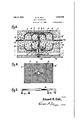
- Numeralllv indicates strips or sheets oiA wiremeslr which: are embedded-'in the side-plates, each havingendPportions I5. which. extend into the area between the side-plates, and at It are indi- In the drawings which illustrate one embodiment of the invention, Fig. 1 is a vertical section on line I-I of Fig. 3, said View showing a pair of blocks, partly broken away, being added to show a lower horizontal course for a wall.
- Fig. 2 is a sectional View showing spacing-means for maintaining the slabs or side-plates of a wall block in relatively parallel position.
- Fig. 3 is a View of a block in longitudinal section on line 3--3 of Fig. 1 to clearly show stabilizing devices for a Wall block.
- Fig. 4 is a view in side elevation showing the use of wire-mesh for reinforcement purposes and Fig. 5 is a side view of a tool for temporary use in supporting the slabs or side-plates in parallel position.
- Each block consists of a pair of rectangular slabs or side-plates, the outer side-plate being indicated at II and the inner plate indicated at I2, the rectangular area between the plates being utilized for reinforcements.
- cated anchor-members made of Wire-mesh or otl'ier. ⁇ foraminous. material, partly embedded. in the,side1platesf and secured by use of fasteners I1, to members. I5, .these members l5 having. end portions which. also. extend. into. the area between thexside-plates. .These sheets.
- Numerals 22 indicate upright reinforcing rods and at 23 are indicated horizontal reinforcing rods, these stabilizing elements being disposed between the side-plates for the several courses of a wall, the number of these elements 22 and 23, and their spacing depending upon thickness and height of the Wall.
- Numeral 24 indicates a filler for the areas between the side-plates, and this ller and also the slabs or side-plates may consist of concrete or other suitable material.
- the anchor-nuts I3 and I4 are disposed midway between the ends of the side-plates, and each anchor-nut I4 is threaded for receiving a supporting-bolt 25 Which projects outwardly of the side-plate I2 for receiving and supporting a bearing-block 26, these bearing-blocks being adapted to support an inner plastered Wall 21 or metallic lath for a wall and to provide airinsulation space 28.
- Numeral 29 indicates a tool for temporary use of an operator when disposing the side-plates in parallel position.
- the upright stabilizing rods 22 may first be placed in position.
- the recesses above mentioned may receive the locking elements 2
- the tool 29 may then be used, the pairs of prongs 3D at the ends of the tool being disposed stridingly, and the length of the tool corresponding to the thickness of the building block.
- (Fig. 4) indicates apertures form-ed in the wire-mesh of members I5 and I6 for receiving the anchor-nut I3 and I4.
- wire-mesh between the side-plates of one block may extend to an adjacent block, and when the areas between the sideplates of the blocks have been lled With adhesive material, each block at its ends will be secured,
Description
July 8, 1941. E. M. HALL 2,248,348
WALL CONSTRUCTION Filed Dec. 15, 1939 2 Sheets-Sheet 1 l .1. a1 aa ai s iw. mv @f ,U
'U 1&0 W i0 la {'152" I I E Edward M.Halu,
#W J ,ZW
`2 Sheets-.sheer g ;:.MHALL.
WALL CONSTRUCTION Filed Dec. 15, i939 ooo o QUDO a,
Edward M.Hu #M attorneg Patented July 8, 1941 UNITED STAT-ESS Nr.1? Q'FFIQE aziasw u WALL' .CONSTEUGTIO*N-I E'dwa'rdM'. Hall, 0malia,',Nb r. ApplicationiDecember. 13, 1939, Serial No. 308,985
' 3' Claims.
Thisinvention relates to `wall construction consistingof rectangular blocks adaptedltobe-laid in' structionthat all partsv may be .handled con.4
veniently by a` single operator who mayfornilthe blocks completely at the time they. are laid4 in the wall', this being an. advantage since a plastic: concrete ller is used for eachzblockf, and-thereby hardening oi each block ispermitted: while: building each course.
. 'Ihe invention includes deadzairspace or insulation for the inner side of the'wall, .and includes other features of advantage as will. be hereafter mentioned. The invention consists 'of-the. new and useful construction, combination and. lar.-
rangement of parts asy described: and. claimed` herein, and as illustrated inv the accompanying. drawings, it. being understood that changes may.
be madeV in form, size, proportions and minor details of construction, said changes being within the scope of the invention as claimed.
Numerals I3 -and I4 indicate anchor-nuts for the-'respective outer and inner slabs orv side-4 plat.e's,the1 anchor-nut for the inner side-platel extending completely' therethrough. Numeralllv indicates strips or sheets oiA wiremeslr which: are embedded-'in the side-plates, each havingendPportions I5. which. extend into the area between the side-plates, and at It are indi- In the drawings which illustrate one embodiment of the invention, Fig. 1 is a vertical section on line I-I of Fig. 3, said View showing a pair of blocks, partly broken away, being added to show a lower horizontal course for a wall. Fig. 2 is a sectional View showing spacing-means for maintaining the slabs or side-plates of a wall block in relatively parallel position.
Fig. 3 is a View of a block in longitudinal section on line 3--3 of Fig. 1 to clearly show stabilizing devices for a Wall block.
Fig. 4 is a view in side elevation showing the use of wire-mesh for reinforcement purposes and Fig. 5 is a side view of a tool for temporary use in supporting the slabs or side-plates in parallel position.
The invention is shown and described in connection with rectangular blocks III adapted to be disposed one upon another in horizontal courses,
the proportions or size for the blocks depending upon the height of the walls to be built and use or occupancy of the building.
Each block consists of a pair of rectangular slabs or side-plates, the outer side-plate being indicated at II and the inner plate indicated at I2, the rectangular area between the plates being utilized for reinforcements.
cated anchor-members. made of Wire-mesh or otl'ier.` foraminous. material, partly embedded. in the,side1platesf and secured by use of fasteners I1, to members. I5, .these members l5 having. end portions which. also. extend. into. the area between thexside-plates. .These sheets. |15- and IS. are mounted; mdwayfbetween their ends,y upon the anchor-units.
Numeralsil38-in'dicate .eye-bolts adapted to be threaded in the :anchor-nuts, and at I9 is indicated a spacing-bar having projections at its ends. for engaging in the apertures of the eye-bolts.
Cof-operating; devices,V suchv as recesses .2@ formjed in: the.horizontal?v edgesvof the side-plates andz suitable locking elements 2 I therein, are' employed. The recesses of an upperblock are dis- -posed -in'register w-ithqthe; recesses of a lower blockgandgbyruse;ofmembers.2| the blocks of the several courses may be maintained in vertical alignment.
Numeral 24 indicates a filler for the areas between the side-plates, and this ller and also the slabs or side-plates may consist of concrete or other suitable material.
The anchor-nuts I3 and I4 are disposed midway between the ends of the side-plates, and each anchor-nut I4 is threaded for receiving a supporting-bolt 25 Which projects outwardly of the side-plate I2 for receiving and supporting a bearing-block 26, these bearing-blocks being adapted to support an inner plastered Wall 21 or metallic lath for a wall and to provide airinsulation space 28.
The side-plates being thus supported by use of ythe tool, it is obvious that the eye-bolts may be rotated for suitable adjustments in the anchornuts, and the spacing-bar When placed in operative position will maintain the side-plates relatively parallel. The tool when removed will permit a horizontal reinforcing rod to be placed in position, and the adhesive ller may then be poured or deposited, and thereafter will become hardened for holding the parts in rmly connected condition as a unit.
Numeral 3| (Fig. 4) indicates apertures form-ed in the wire-mesh of members I5 and I6 for receiving the anchor-nut I3 and I4.
Among some of the advantages to be derived by use of the invention it may be stated that the costly wall forms usually employed are not required. Also all expensive wall finishing may be dispensed with, and the outer slab or side-plate of each block may be nished before the block is used, and may be provided with any selected color, texture or surface treatment.
It is obvious that the wire-mesh between the side-plates of one block may extend to an adjacent block, and when the areas between the sideplates of the blocks have been lled With adhesive material, each block at its ends will be secured,
on account of this construction, with the ends of blocks adjacent thereto. Since labor of only ordinary skill is required, the use of the invention will be an advantage as an expense-saving feature.
I claim as my invention:
1. In wall construction, concrete slabs laid in horizontal courses providing an outer and an inner Wall-section and a channel between said wall-sections, anchor-nuts disposed opposite to each other embedded in the wall-sections and extending to the channel, eye-bolts threaded in the anchor-nuts, spacing-bars spanning the channel and mounted in the eye-bolts, sheets of Wire mesh mounted on the anchor-nuts each having a part embedded in a wall-section and having an end-portion extending into said channel, and concrete material in said channel for embedding therein the spacing-bars and end-portions of said sheets of Wire mesh.
2. In Wall construction, concrete slabs laid in horizontal courses providing an outer and an inner wall-section and a channel between said wall-sections, horizontal stabilizing-rods midway between the Wall-sections, vertical stabilizingrods in the channel intersecting the horizontal stabilizing-rods, anchor-nuts arranged opposite to each other in pairs and embedded in the wallsections, eye-bolts threaded in the anchor-nuts, spacing-bars disposed transversely of the channel and mounted in the eye-bolts, sheets of Wire mesh arranged in opposed pairs, the sheets of each pair being riveted to each other and mounted on an anchor-nut and having parts embedded in a Wall-section and having relatively spaced end-portions extending into the channel, and a concrete iller in the channel for embedding therein the said reinforcing-rods, portions of the eye-bolts, the spacing-bars and said end-portions of wire mesh sheets. V
3. In Wall construction, rectangular, concrete slabs laid one upon another providing a pair of relatively spaced, parallel side-sections and an intermediate channel, pairs of opposed anchornuts in the side-sections, eye-bolts-threaded on the anchor-nuts and extending into the channel, spacing-bars each spanning the channel and de tachably mounted on the eye-bolts of a pair of opposed anchor-nuts, sheets of wire mesh secured to each other in pairs and provided withA apertures for receiving the anchor-nuts therein, the sheets of each pair having parts embedded in the side-sections and having end-portions disposed in spaced relation in the channel, and concrete material in said channel for embedding therein the eye-bolts, said spacing-bars and the spaced end-portions of said sheets of wire mesh.
EDWARD M. HALL.
Priority Applications (1)
| Application Number | Priority Date | Filing Date | Title |
|---|---|---|---|
| US308985A US2248348A (en) | 1939-12-13 | 1939-12-13 | Wall construction |
Applications Claiming Priority (1)
| Application Number | Priority Date | Filing Date | Title |
|---|---|---|---|
| US308985A US2248348A (en) | 1939-12-13 | 1939-12-13 | Wall construction |
Publications (1)
| Publication Number | Publication Date |
|---|---|
| US2248348A true US2248348A (en) | 1941-07-08 |
Family
ID=23196179
Family Applications (1)
| Application Number | Title | Priority Date | Filing Date |
|---|---|---|---|
| US308985A Expired - Lifetime US2248348A (en) | 1939-12-13 | 1939-12-13 | Wall construction |
Country Status (1)
| Country | Link |
|---|---|
| US (1) | US2248348A (en) |
Cited By (20)
| Publication number | Priority date | Publication date | Assignee | Title |
|---|---|---|---|---|
| US2633735A (en) * | 1948-04-02 | 1953-04-07 | John A Dondero | Building construction |
| US2658379A (en) * | 1947-03-03 | 1953-11-10 | Allen Frank Richard | Portable brick wall |
| US2715829A (en) * | 1948-09-23 | 1955-08-23 | Gunther K E Kleeberg | Building unit of spaced concrete walls |
| US3277626A (en) * | 1963-10-17 | 1966-10-11 | Dur O Wal National Inc | Double shank adjustable wall tie |
| US3292336A (en) * | 1963-10-17 | 1966-12-20 | Dur O Wal National Inc | Reversible wall tie |
| US3300939A (en) * | 1963-10-17 | 1967-01-31 | Dur O Wal National Inc | Combination adjustable tie and joint reinforcement for wall constructions |
| US3676967A (en) * | 1970-07-01 | 1972-07-18 | Augustus Frati | Forms for concrete wall construction |
| EP0693597A1 (en) * | 1994-07-18 | 1996-01-24 | Plastedil S.A. | Modular dowel assembly for fixing a lining element to a panel of an expanded plastic material and structural element incorporating said assembly |
| US5809725A (en) * | 1995-07-18 | 1998-09-22 | Plastedil S.A. | Sectional nog structure for fastening a covering element to a foamed plastic slab and construction element incorporating said structure |
| US5887401A (en) * | 1997-07-24 | 1999-03-30 | Eco-Block Llc | Concrete form system |
| US6170220B1 (en) | 1998-01-16 | 2001-01-09 | James Daniel Moore, Jr. | Insulated concrete form |
| US6314697B1 (en) | 1998-10-26 | 2001-11-13 | James D. Moore, Jr. | Concrete form system connector link and method |
| US6318040B1 (en) | 1999-10-25 | 2001-11-20 | James D. Moore, Jr. | Concrete form system and method |
| US6336301B1 (en) | 1998-11-05 | 2002-01-08 | James D. Moore, Jr. | Concrete form system ledge assembly and method |
| US6438918B2 (en) | 1998-01-16 | 2002-08-27 | Eco-Block | Latching system for components used in forming concrete structures |
| US6481178B2 (en) | 1998-01-16 | 2002-11-19 | Eco-Block, Llc | Tilt-up wall |
| US20030167713A1 (en) * | 2000-05-26 | 2003-09-11 | Yost Louis L. | Corner assemblies for concrete form panels |
| US20050108963A1 (en) * | 2002-12-02 | 2005-05-26 | Wostal Terry K. | Collapsible concrete forms |
| US20070278038A1 (en) * | 2006-05-30 | 2007-12-06 | Logan Wade Archer | Method and apparatus for securing a scaffold to a building |
| US9333672B1 (en) | 2015-04-09 | 2016-05-10 | S.G.L. Gavish Yizum U'vnia, Ltd. | Hardenable material structure construction apparatus and method |
-
1939
- 1939-12-13 US US308985A patent/US2248348A/en not_active Expired - Lifetime
Cited By (26)
| Publication number | Priority date | Publication date | Assignee | Title |
|---|---|---|---|---|
| US2658379A (en) * | 1947-03-03 | 1953-11-10 | Allen Frank Richard | Portable brick wall |
| US2633735A (en) * | 1948-04-02 | 1953-04-07 | John A Dondero | Building construction |
| US2715829A (en) * | 1948-09-23 | 1955-08-23 | Gunther K E Kleeberg | Building unit of spaced concrete walls |
| US3277626A (en) * | 1963-10-17 | 1966-10-11 | Dur O Wal National Inc | Double shank adjustable wall tie |
| US3292336A (en) * | 1963-10-17 | 1966-12-20 | Dur O Wal National Inc | Reversible wall tie |
| US3300939A (en) * | 1963-10-17 | 1967-01-31 | Dur O Wal National Inc | Combination adjustable tie and joint reinforcement for wall constructions |
| US3676967A (en) * | 1970-07-01 | 1972-07-18 | Augustus Frati | Forms for concrete wall construction |
| EP0693597A1 (en) * | 1994-07-18 | 1996-01-24 | Plastedil S.A. | Modular dowel assembly for fixing a lining element to a panel of an expanded plastic material and structural element incorporating said assembly |
| US5809725A (en) * | 1995-07-18 | 1998-09-22 | Plastedil S.A. | Sectional nog structure for fastening a covering element to a foamed plastic slab and construction element incorporating said structure |
| US5887401A (en) * | 1997-07-24 | 1999-03-30 | Eco-Block Llc | Concrete form system |
| US6609340B2 (en) | 1998-01-16 | 2003-08-26 | Eco-Block, Llc | Concrete structures and methods of forming the same using extenders |
| US6526713B2 (en) | 1998-01-16 | 2003-03-04 | Eco-Block, Llc | Concrete structure |
| US6170220B1 (en) | 1998-01-16 | 2001-01-09 | James Daniel Moore, Jr. | Insulated concrete form |
| US6481178B2 (en) | 1998-01-16 | 2002-11-19 | Eco-Block, Llc | Tilt-up wall |
| US6363683B1 (en) | 1998-01-16 | 2002-04-02 | James Daniel Moore, Jr. | Insulated concrete form |
| US6438918B2 (en) | 1998-01-16 | 2002-08-27 | Eco-Block | Latching system for components used in forming concrete structures |
| US6314697B1 (en) | 1998-10-26 | 2001-11-13 | James D. Moore, Jr. | Concrete form system connector link and method |
| US6336301B1 (en) | 1998-11-05 | 2002-01-08 | James D. Moore, Jr. | Concrete form system ledge assembly and method |
| US6318040B1 (en) | 1999-10-25 | 2001-11-20 | James D. Moore, Jr. | Concrete form system and method |
| US20030167713A1 (en) * | 2000-05-26 | 2003-09-11 | Yost Louis L. | Corner assemblies for concrete form panels |
| US6826880B2 (en) * | 2000-05-26 | 2004-12-07 | Louis L. Yost | Corner assemblies for concrete form panels |
| US20050108963A1 (en) * | 2002-12-02 | 2005-05-26 | Wostal Terry K. | Collapsible concrete forms |
| US7347029B2 (en) | 2002-12-02 | 2008-03-25 | Wostal Terry K | Collapsible concrete forms |
| US20070278038A1 (en) * | 2006-05-30 | 2007-12-06 | Logan Wade Archer | Method and apparatus for securing a scaffold to a building |
| US8316992B2 (en) * | 2006-05-30 | 2012-11-27 | Logan Wade Archer | Method and apparatus for securing a scaffold to a building |
| US9333672B1 (en) | 2015-04-09 | 2016-05-10 | S.G.L. Gavish Yizum U'vnia, Ltd. | Hardenable material structure construction apparatus and method |
Similar Documents
| Publication | Publication Date | Title |
|---|---|---|
| US2248348A (en) | Wall construction | |
| US2316819A (en) | Wall structure | |
| US2306107A (en) | Form for molding building members | |
| US2057732A (en) | Mold for casting a supporting ledge for brick veneer | |
| US1784271A (en) | Conduit and method of constructing the same | |
| US2096629A (en) | Construction of roofs, floors, ceilings, and the like | |
| US2250020A (en) | Molding apparatus | |
| US2776559A (en) | Block wall | |
| US1911957A (en) | Spacer for reenforcement rods | |
| US1700512A (en) | Method and apparatus for constructing building units | |
| US1951421A (en) | Wall structure | |
| US940463A (en) | Mold. | |
| US2098929A (en) | Block or slab molding means and method | |
| US2154390A (en) | Concrete slab construction | |
| US2185860A (en) | Shuttering device for the building of ferroconcrete structures | |
| US1725239A (en) | Support for concrete reenforcements | |
| US2275738A (en) | Form for molding concrete walls or columns | |
| US1527551A (en) | Concrete construction | |
| US1193484A (en) | blleet | |
| US2186097A (en) | Adjustable form for sectional concrete burial vaults | |
| US1220915A (en) | Reinforced concrete construction. | |
| US2107334A (en) | Partition | |
| US3223378A (en) | Reinforced concrete structures having formwork embedded therein | |
| US2659123A (en) | Apparatus for making concrete elements | |
| US2527035A (en) | Concrete roof |