US2217153A - Apparatus for drying - Google Patents
Apparatus for drying Download PDFInfo
- Publication number
- US2217153A US2217153A US133344A US13334437A US2217153A US 2217153 A US2217153 A US 2217153A US 133344 A US133344 A US 133344A US 13334437 A US13334437 A US 13334437A US 2217153 A US2217153 A US 2217153A
- Authority
- US
- United States
- Prior art keywords
- switch
- tumbler
- drying
- arm
- motor
- Prior art date
- Legal status (The legal status is an assumption and is not a legal conclusion. Google has not performed a legal analysis and makes no representation as to the accuracy of the status listed.)
- Expired - Lifetime
Links
Images


Classifications
-
- F—MECHANICAL ENGINEERING; LIGHTING; HEATING; WEAPONS; BLASTING
- F26—DRYING
- F26B—DRYING SOLID MATERIALS OR OBJECTS BY REMOVING LIQUID THEREFROM
- F26B11/00—Machines or apparatus for drying solid materials or objects with movement which is non-progressive
- F26B11/18—Machines or apparatus for drying solid materials or objects with movement which is non-progressive on or in moving dishes, trays, pans, or other mainly-open receptacles
- F26B11/181—Machines or apparatus for drying solid materials or objects with movement which is non-progressive on or in moving dishes, trays, pans, or other mainly-open receptacles the receptacle being a foraminous, perforated or open-structured drum or drum-like container, e.g. rotating around a substantially horizontal or vertical axis; the receptacle being multiple perforated drums, e.g. in superimposed arrangement
-
- F—MECHANICAL ENGINEERING; LIGHTING; HEATING; WEAPONS; BLASTING
- F26—DRYING
- F26B—DRYING SOLID MATERIALS OR OBJECTS BY REMOVING LIQUID THEREFROM
- F26B21/00—Arrangements or duct systems, e.g. in combination with pallet boxes, for supplying and controlling air or gases for drying solid materials or objects
- F26B21/06—Controlling, e.g. regulating, parameters of gas supply
- F26B21/10—Temperature; Pressure
Definitions
- This invention relates to apparatus useful in dry cleaning, and more particularly to drying materials which have previously been treated with an inflammable cleaning solvent.
- Dry cleaning processes may-be broadly classified in two categories, viz.: those employing (1) inflammable solvents, such as benzine, gasoline, cleaners naphtha, Stoddard solvent, and the hydrogenation products of naphthalene -tetralin and decalin; (2) the chlorinated hydrocarbon products such as carbon tetrachloride and tetrachloethylene.
- inflammable solvents such as benzine, gasoline, cleaners naphtha, Stoddard solvent, and the hydrogenation products of naphthalene -tetralin and decalin
- chlorinated hydrocarbon products such as carbon tetrachloride and tetrachloethylene.
- Stoddard solvent a mixture of petroleum distillates, having a flash point in the neighborhood of F., has had a wide use in dry cleaning processes, but since its flash point is within the range of possible workroom temperatures, its use, and similarly, the use of solvents of lower flash point, has been penalized in-the sense that various statutes, ordinances, and rulings of fire insurance rate-setting boards have required dry cleaning operations involving the use of such inflammable solvents to be carried on in separate ordetached buildings of special construction.
- Dry cleaning according to the open batch system usually includes handling a batch of clothing or other articles in successive stages, as follows: The batch is first treated in a washing machine, preferably of the horizontal cylinder type, by agitation in intimate contact with the solvent for a period of sufficient duration to accomplish the desired degree of cleansing. It.
- a further object of' the invention is to provide improved control mechanism and safety devices which are automatic in operation. More specifically, it is an aim of the present invention to maintain at all times safe temperatures within the apparatus in relation to the flash point of the solvent contained in the materials treated and in relation to the vapor concentration during the various stages of the drying cycle.
- Fig. 1 is a front elevation of a drying tumbler embodying features of the present invention
- Fig. 2 is a right side elevation thereof
- Fig. 3 is a left side elevation thereof 9
- Fig. 4 is a back elevation of the tumbler
- Fig. 5 is a cross-section taken on line 5--5 of Fig. 4;
- Fig. 6 is an enlarged sectional detail of the cylinder construction on line 66 of Fig. 5;
- Fig. 7 is a top plan view of the rear portion of the tumbler showing the location of certain of the operating and control devices;
- Fig. 8 shows on a larger scale the upper portion of the tumbler, and the control mechanism in the same position it occupies in Fig. 3, the shell door being in open position;
- Fig. 9 is a view similar to Fig. 8 showing the control mechanism in a different position and the shell door closed;
- Fig. 10 is a view of certain elements of the control mechanism in positions different from those occupied by the same elements in Figs. 3, 8, and 9;
- Fig. 10A is a view showing the control elements of Fig. 10 in still different positions;
- Figs. 11 and 12 are respectively back and side elevations, on an enlarged scale, of the belt pulley and belt shifting header assembly
- Figs. 13 and 14 are respectively elevations of mechanically and electrically actuated switch mechanisms which become effective at different stages of the drying cycle to control certain phases of that cycle;
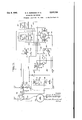
- Fig. 15 is a wiring diagram pertaining to the apparatus and'devices shown in the preceding figures.
- Fig. 16 is a somewhat diagrammatic view of a half-turn motor and circuit-maintaining switch therefor;
- Fig. 17 is a somewhat diagrammatic view of a timing device
- the apparatus and controls therefor may be modified to suit the special conditions under which dry cleaning takes place. Having in mind the facts: that the treatment of the clothes in the drying tumbler is first conducted at a temperature predetermined in relation to the flash point of the particular solvent used in the preceding steps of the dry cleaning process, and that the length of this preliminary drying stage is determined by test as sufficient to dry the clothing to a degree making it possible and safe thereafter to submit the clothing in the drying tumbler to highest heat, in order rapidly to complete the drying of the clothes and effect efficient deodorization thereof, it will be evident that in the case of a solvent having a flash point substantially above any possible workroom temperature the heat during the preliminary heating period may with safety be maintained at a temperature well above that of the workroom but substantially below the flash point of the particular solvent used.
- Drying apparatus for a solvent of this nature will include heating means and heat and time controls, adapted to heat the air entering the tumbler to the desired low heat drying temperature and maintain that temperature long enough to accomplish the desired degree of drying.
- the apparatus and controls will be of a character to render possible holding the temperature of the air in the drying tumbler during the low heat drying period not only below the flash point of the solvent, but also, if necessary, below the temperature of the workroom.
- dampers are connected in predetermined relationship by means of an adjustable rod 23, the length of the rod and its 'mode of attachment to the two dampers being such that whenever one of said dampers is open the other will be closed.
- the operation of the dampers is automatic and is controlled by means of a half-tum motor P, the crank pin P of which is connected by means of an adjustable connecting rod 24 to the crank arm 25 mounted upon the shaft 2
- the heater box I4 is divided into two compartments l4 and I4 by means of a vertical partition 26 which extends downwardly from the top plate of the coil box to within a short distance of the bottom of the coil box. Thus the two coil box compartments communicate at their lower ends adjacent the lower air inlet I6. Located in the compartment I4 is a steam coil 21 and in the compartment I4 is a steam coil 26. Air from the inner compartment I4 is led to the top of the tumbler and admitted to the tumbler drum through an opening 29 in the inner shell I2. The outlet from the cylindrical drum chamber is through an opening 30 at the bottom of the shell l2, opposite the opening 29.
- This outlet 30 forms a passage for the air into the lower part of the tumbler housing beneath the drum chamber, where there is located a rotary fan 3
- the outlet of the fan housing 33 is at 34 projecting through the rear wall of the tumbler housing near the bottom thereof.
- the fan 3! is driven by a direct connected motor 35 and serves to draw air through the air inlet l5 over both coils 28 and 27, or through air inlet l6 over the inner coil 21 only, thence by way of the air inlet 29, down through the drum chamber, and by way of outlet 30 into the lower part of the tumbler housing, whence the air is exhausted to the atmosphere, preferably outside of the building in which the tumbler is installed.
- the coil box In order that heat shall not be transferred from the coil box to the-tumbler drum otherwise than by the heated air drawn through the drum, the coil box should be well insulated from the drying space within the tumbler. It is therefore desirable to insulate the coil box, as by means of an adequate heat-insulating medium, as indicated at l5l in Fig. 5.
- the steam connections to and from the independently connected coils 21 and 28 may best be understood by reference to Figs. 1, 2, 4 and 7.
- Live steam is brought to a fitting 36 which connects with a cross fitting 3! having connections to the upper ends of both the inner and outer steam coils 21 and 28.
- Connection from the fitting 36 to the cross fitting 31 is made through a main steam line 39 and a branch steam line 49..
- a shutoff valve 4i operated automatically by means of a lever 42 suitably connected to a crank arm 43 fastened upon the damper-operating shaft 21.
- the operation of the valve 44 is controlled by the temperature of the air at the top of the tumbler before it has access to the tumbler drum containing the materials being dried.
- Steam coils 21 and 28 are connected at their lower ends by .means of pipes 21 and 28 to the steam return pipe I53.
- the tumbler drum H is journaled in bearings 46 mounted on brackets 41 secured to the side plates of the tumbler housing.
- the jack shaft 56 carries a tight pulley 54 and a pair of loose pulleys 55, 56.
- the header worm 51 which has a pin-and-slot connection with the hub of the loose pulley 56 so as to be driven thereby.
- Mounted upon the header bracket 53 in coaxial relation to the shaft 50 is a header arm assembly comprising the support 58, to which is pivotally connected the belt shifter fork 59.
- the header arm assembly includes a worm gear 60 on support 58 meshing with the worm 51, and a reciprocating slide shaft 6i, slidably and rotatably mounted at the upper end of the support 58 in a block 62. Projecting from the block 52 parallel to the shaft 6! is a guide rod 63. A weighted pin or header fall 64 secured to and extending at right angles to the slide shaft 6!
- This shifter sleeve carries a forked arm 69 cooperating with the guide rod 63 to prevent the shifter sleeve 61 from rocking about the axis of the shaft 6
- This shifter sleeve carries a shifter arm Ill extendingin opposite directions above the belt pulleys and provided with belt guide blocks H, 12, each equipped with a belt guide l3.' The belt guides are so disposed that belt on to the tight pulley will effect a reversal.
- belts l4 and I5 connect with a suitable line shaft (not shown).
- auxiliary air inlet 18 communicating directly with the air outside the tumbler housing and serving as a vent when the fan is not running.
- This air inlet 18 may be closed by means of a vent damper l9 pivotally mounted upon arms 88 which themselves are rotatably mounted upon brackets 8I secured to the housing.
- the rock shaft 82 which supports the arm 88 carries a crank arm 83 connected by means of a link 84 to one end of a counterbalanced lever 85 pivotally supported at 86 upon the tumbler housing.
- the weight lever 85 has mounted at its free end a counterweight 88, the tendency of which is to maintain the vent damper 19 always in' an open position.
- this damper is associated with other automatic control mechanism.
- the means for shifting the header-fall into or out of engagement to cause belt drive of the tight pulley on the jack shaft comprises an operating lever 89 which, with other operating parts, is mounted upon a cast bed-plate 98 bolted to the side sheet of the tumbler housing.
- the operating lever 89 is pinned to a shaft 9
- a roller 92 Attached to one end of the operating lever is a roller 92 adapted, when the lever 89 is thrown to engage the belt-shifting header-fall in operating position, to come in contact with a camming arm 93, moving said arm 93 to shift a switch A, the purpose of which will be explained hereinafter.
- crank arm 94 Pinned to the shaft 9
- a branch arm 96 of crank arm 96 is con- The operation of nected by an adjustable link 98 to a gear segment 99 rotatably mounted on a pin I88 fixed to a casting I8I which is adjustably mounted on the side of the tumbler housing toward the rear of said housing relative to the position of the bed-plate 98.
- the gear segment 99 meshes with teeth cut on a rotating sleeve I82 rotatably mounted on a pin I83 carried by the bed-plate I8I (see Fig. 4).
- the rotatable sleeve I82 surrounds an extension of the reciprocating slide shaft 8
- is provided at the end nearest the tumbler with a pin I84 which projects through a longitudinal slot I85 in the sleeve I82.
- This motion of the gear segment causes rotation of the sleeve I82 and because of the engagement of the pin I84 with a side of the slot I85 produces rotation of the shaft 6
- Safety devices associated with mechanical control mechanism There will now be described means connected with this operating mechanism for preventing the opening of the shell door I3 when the beltshifting header is engaged and also for preventing any actuation of the operating mechanism to start rotation of the drum when the shell door is open. There will also be described means associated with this operating mechanism for controlling the operation of the vent damper 19 in association with magnetic means adapted to open the vent damper 19 in case of failure of current to the fan motor 35.
- crank arm 96 is provided with another branch arm 96 which serves to form an interlock between the operating lever 89 and the shell door I3.
- the latter is equipped with an abutment casting I86 so shaped and disposed that the shell door can be opened only when the operating lever 89 is in its forward or headerdisengaging position, as will be clearly understood by comparing the positions of the parts in Figs. 8 and 9.
- the abutment I88 prevents rearward movement of the branch arm 96 and thus rearward movement of operating lever 89, when the tumbler door stands in open position and, reversely, the said arm 96 opposes movement of the abutment member 9 I88 should an attempt be made to open the door I3 while the operating lever 89 stands in its 75 rearward position, as shown in Fig. 9.
- the starting lever 89 be-put in engagement position unless current is being supplied to the fan motor, it follows that the dryer cylinder can not be set in operation until after the fan is started.
- the crank arm 96 is also provided with a third branch arm 96 which carries pivotally mounted thereon a latch member I01, the movement of which is restrained in one direction by means of a spring I08 attached at one end to the latch member I01 and at the other end to a fixed pin I09.
- This latch member I01 normally stands in interlocking engagement (see Figs. 8 and 9) with a coacting projection IIO formed upon a slide block III, which is constrained to a straightline motion by three rollers H2 mounted upon the bed-plate 90.
- Attached to the slide block III is a spring housing II3 which by means of a spring H4, a bolt H5, and a link IIB connects the slide block III with a crank arm II1, pinned to the vent damper shaft 82.
- a solenoid H8 to the core oi'which is attached a weight II9 of sufilcient mass to cause the immediate descent of the solenoid core whenever excitation ceases.
- this solenoid is energized under normal working conditions immediately after the closing of a magnetic starter, indicated in the drawings by the letters MS, whose position on the tumbler housing is substantially as disclosed in Figs. 1 and 3.
- a trigger I15 lying in back of the bell crank I22 At one end this trigger is provided with a detent hook I15 adapted to engage the projection IIO on slide III- when the slide is drawn down to the position shown in Fig. 9 by the latch member I01, as above described.
- the slide will thus be held in its lower position by the trigger even though the operating lever 89 be thrown to its header disengaged position, as is clearly shown in Fig. 10A, which shows the latch member I01 in its raised position and the trigger I15 interlocked with the slide projection IIO.
- Trigger I15 tends always to follow up any movement of the bell crank I22 in a counterclockwise direction by reason of its weighted end I11. However, when the bell crank I22 is moved in a clockwise direction by the dropping of the solenoid core, the trigger is also swung in the same direction under the compulsion of an adjustable abutment bolt I18 carried by the bell crank.
- the movement of the bell crank I22 in response to the dropping of the solenoid weight is to the position shown in Fig. 10 where the upper arm of the bell crank moves under the projecting surface I26 of the latch member I01 and so serves as a strut to prevent the operating lever 89 from being moved to its header-engaged position until current has been restored and the solenoid re-energized.
- the operating lever 89 is in header-disengaged position and slide III in its lower position (damper 19 closed and held in place by trigger I15 as in Fig. 10A) the movement of the bell crank I22 in response I to the dropping of the solenoid weight will swing the bell crank in a clockwise direction and cause the trigger I15 to release the slide projection.
- Fig. 6 is a section taken on line 6-6 of Fig. 5 and shows the junction of the cylinder head I28 with the cylindrical portion of the drum.
- the drum is equipped with a sliding door I29 having atits lateral edges slide strips I30 slidably mounted in the guideway formed between the cylinder band I3I and an inner band I32. These bands are separated by a filler strip I33. Between the inner band I32 and the outwardly turned flange I34 of the head I28 there is disposed an annular canvas strip I35. All of these parts are held together by a circumferential row of bolts I36 and nuts I31.
- Such an annular strip of canvas I35 is provided at each end of the drum. They engage the tumbler housing at the ends of the drum and thus prevent bypassing of the heated air around the ends of the drum.
- felt wipers I38 are used (see Fig. 5) which extend longitudinally of the periphery of the drum diametrically opposite one another, their outer edges engaging the interior of the cylindrical shell I2.
- the magnetic starter MS has been mentioned, as have the half-turn motor P and the singlepole, double-throw switch A operated by the hand-operating lever 89.
- a single-pole, doublethrow switch B which is operated by the halfturn motor concurrently with the operation by said motor of the air dampers to the coil box and the steam valve 4
- the half-turn motor operates first to terminate the low heat period of operation, and operates again to terminatethe high heat period of operation. After its second operation the half-turn motor will have returned to its initial position and be in condition to control the operations of 'a succeeding drying cycle.
- the electrical connections to the half-turn motor are completed at the end of the low heat period through the operation of a low heat timer designated LHT, and the said second operation to terminate the high heat period is controlled by a high heat timer designated HHT.
- the half-turn motor P will be seen to be a single phase motor of the squirrel cage type, comprising a stator and rotor.
- the stator winding is connected between one side of a power line and a commutator ring P3 forming part of a control switch for the motor.
- This switch comprises a brush P2 rotated in synchronism with the rotor of the half-turn motor, the mechanical connection between the brush shaft and the rotor shaft being indicated by the reference character PI5.
- An outer commutator concentric with P3 comprises four alternating short and long segments P4, P5, P6, and P1. Segments P5 and P1 are, in fact, integral, being connected by the members P8 and P9.
- segments P4, P5, P6 and P1 are successively connected under predetermined conditions of tumbler operation and at predetermined intervals of time with the other side of the abovementioned power line.
- the connections to the short segments P4 and P8 are completed respecother half revolution is initiated.
- the brush P2 rides off of P4 or P6 onto P5 or P1
- the excitation of the motor for the remainder of the respective half-turn is maintained through those segments.
- the motor will stop when its brush rides off of P5 or P1 onto the short segments P6 or P4.
- Timers LHT and HHT control respectively switches C and D in the half-turn motor circuits.
- a spring I tends normally to hold the disk I15 out of engagement with the disks I14 and I18 when the magnet TI is unexcited.
- Shaft I19 drives a timing disk I8I which may be calibrated to indicate minutes.
- Rotatable with the timing disk I8I is a hand I82 which may be adjustably positioned with respect to a zero position on the dial by means of knurled nut I83.
- a lug I84 At the end of the hand I82 is a lug I84, adapted at the zero position to engage a coacting lug I carried by an arm I86 rotatable with the switch arm I10 about the axis I81, against the tension of the spring I12.
- the timing hand will be set back from the zero position on the dial a distance determined by the number of minutes for which the timer is desired to function.
- the motor starts to rotate and'the magnet this is done the friction disk I15 is drawn out ofengagement with disks I14 and I18 by the spring I80.
- Spring I88 then returns the timing dial and hand to their original positions and spring I12 returns the .switch arm I10 into contact with switch contact I1I.
- the parts are reset to function all over again when next the switch B is closed.
- the wiring diagram also shows a green signal lamp marked Green and a red signal lamp marked Red. serves to operate the switch H, a magnetic contactor J which serves to operate the switch M,
- thermostatic control switch F the bulb for operating which is indicated at I39 in Fig. 7 where it is shown disposed in the air passage leading to the top of the tumbler cylinder in a position opposite the thermostat bulb 45.
- the bulb I39 is connected to the switch F by means of flexible tubing I40.
- the thermostatic control of the switch F should be such that the switch will'close when the temperature in the air passage falls to or below the temperature setting of the thermostatic valve 44. It will be understood that both the thermostatic switch F and the thermostatic valve 44 are controlled by the temperature of the air entering the tumbler drum.
- LI and L2 indicate respectively the two sides of a power line entering the magnetic starter MS.
- the line LI is connected by the switch contact arm AI in the upper position of that arm through switch contacts A2 and A3 to the starting switch of the magnetic switch MS. This connection only obtains when the machine starting lever 89 stands in its forward or disengaged position.
- the momentary closing of the starting switch indicated on the drawings by the word Start, completes a circuit through the normally closed stop switch, indicated by the word Stop, through the magnet coil I4I of the magnetic starter. The energizing of this coil closes the main circuit contactors I42, I43 and I44, and
- a magnetic contactor G which ately starts the tumbler fan in operation, and since at this time the tumbler vent damper 19 is open, atmospheric air is-drawn in at the top of the tumbler through the tumbler cylinder and Some air will also be drawn through the open lower rear damper 20, over the inner steam coil 21, the latter being at this time under the control of the thermostatic valve 44, into the' tumbler drum chamber. Should, forany reason, the fan motor not start, thermal elements in the magnetic starter, indicated at land I41, will heat up and; after a few seconds of-this abnormal condition, throw the main switch to open position. It will be noted that the line L2 has a branch L2A which is closed by the switch contact I48, and also that a branch line LIA takes 01!
- the switch F is normally held in open position at temperatures above the selected temperature at which the apparatus is to operate during the low heat period, as, for instance, F. If, at the beginning of a cycle, the temperature stands below or at 140 F., the switch F will be closed and a circuit will be completed from LIA through switch contact K, through the coil of the mag netic contactor J and back to the line L2A. Thus, the magnetic contactor will be energized and drawing up its core will complete circuits respectively by means of switch contacts MI and M2 from line LIA through magnetic contactor J and solenoid I I8. Thus, the solenoid will become energized and by the raising of its core open the circuit through the switch K, the magnetic switch J, M thereafter being maintained by current flowing through the switch contact M and its connections.
- Switch K (see Fig. 3) is mounted upon the tumbler housing adjacent the solenoid II8. Its interior contact member, not shown, is operably associated with an exterior arm KI, normally biased, as by a spring K2, to hold the switch K in open position whenever permitted to act through the energization of the solenoid II8. Upon de-energization of the solenoid, the dropping ofthe weight H8 produces movement of the arm KI to close the switch K.
- switch 0 in the low heat timer will be closed, thus connecting the halfturn motor commutator segment P4 with the line LI, and as at this time the half-tum motor switch arm or brush P2 occupies the position shown in Fig. 15, the circuit will be completed through the half-turn motor to the line L2A. Further, when the half-turn motor is thus conditioned the lower air damper 28 will be open, the upper damper I9 closed, and the steam valve M will also be closed, steam being admitted to the steam coils through the thermostatic valve 44.
- the energization of the half-turn motor starts it upon its first half revolution, requiring a short period of perhaps thirty seconds for completion. After approximately one-tenth of this half revo lution, or after an interval of' three seconds has elapsed, the brush P2 moves off segment P4 on to segment P5, and thus becomes connected directly with line LIA. For the rest of its half revolution the motor is energized from LIA through the motor coils back to L2A. At the end of the half revolution the brush moves off segment P5 on to segment P6 which at this time is not connected with line LI, The half-turn motor accordingly stops after making its half turn.
- each half rotation of the half-turn motor changes the position of the parts of the switch B.
- This may be best understood by reference to Figs. 7 and 13.
- a cam PI 8 Upon one end of the shaft of the half-turn motor P there is a cam PI 8.
- a roller B8 carried by a rocker arm B'I mounted upon a rock shaft B8 rides on this cam, rocking the rock shaft first in one direction and then back again during succeeding half revolutions of the half-turn motor.
- This rocking movement acting through an arm B9 depresses or permits to rise a switch plunger BI I. It is thought unnecessary to show the interior arrangement of the switch contacts, which have been designated BI, B2, B3, B4, and B5, in the wiring diagram.
- switch D is closed completing a circuit through I55 to contact P6 of the half-turn motor which is energized and makes a second half revolution back to its original position, This movement reverses the air intake dampers I9 and 20, and closes the steam valve 4I, so that steam now can only be admitted to the steam coils through the thermostatic valve 44.
- the time setting of the high heat timer is determined by the 3 period necessary completely to dry and deodorize the load.
- the second half revolution of the half-turn motor shifts the contact member BI of switch B, breaks the circuit between B2 and B3 and reconnects contacts B4 and B5.
- the high heat timer is de-energized and returns to zero position and the red light is cut out of circuit.
- the temperature of the air passing through the tumbler may be carried well above 200 F., because by this time only a small amount of solvent remains in the clothing and it is thus impossible to develop an explosive mixture in the dryer;
- Cooling period of ope ation Under some conditions the cycle of operations might terminate here, but it has been found in practice that the time usually consumed to unload and reload the tumbler is insufiicient to cool the tumbler to a temperature below the flash point of the solvent, that is, the temperature established for the low heat period. It has been found desirable,. therefore, in order to secure complete safety, to introduce a cooling period im-- mediately succeeding the high heat period in order that the temperature of the air entering the dryer may reduce to the temperature setting of the thermostatic valve 44.
Description
Oct. 8, 1940. e. E. BOWDOIN ET AL 2,217,153
APPARATUS FOR mums Original Filed Oct. 12, 1935 '12 Sheets-Sheet 1 START STOP inventors geozye E. Baum oil: VlB ZZZL'am Strobrid 6- (It omega G. E. aownom ET A 2,217,153
APPARATUS FGR DRYING I Original Filed 00 12, 1935 12 Sheets-Sheet 2 Oct. 8. 1940. G. E. BOWDOIN Er AL 2,217,153
APPARKTUS FOR. DRYING Original Filed 00th. 12., 193.5 12 Shae tsSheet 3 Oct. 8, 1940. e. E. Bowoom ET AL I 2,217,153
APPARATUS-FOR DRYING ofi iaal Filed Oct. 12, 1935 1.2 sh ts-sheet 4 5 Snnentors gem-ye 1L. BowgKoin VVL'ZZL'arrL Strobriclje BY Chm-news i 1940- G. E. BOWDOIN ET AL 2,217,153'
APPARATUS FOR DRYING riginal Filed Oct. 12, 1935 1a Sheets-Sheet.- s
William Strobriolye BY @kflh QUMMQ I"/ M 1940- G. E. BOWDOIN 5T M. 2,217,153
APPARATUS FOR DRYING Original- Filed Oct. 12-, 1935 I 12 Sheets-Sheet 6 mentors Qeorgc/e E. Bowoloin William. Sirobrzldye BY 14 010%; QM rAL WM/ C(tt megs 1940- v e. E. sownom ET AL 2,217,153
APPARATUS FOR 1mm Original Filed on. 12; 1935 12 Sheets-Shut 7 3110mm: Qeorye E. Bowdoin William ,Stroridge BY 963%, (L-z; hw
" attorneys Oct. 8, 1940. G Bowpom 1- AL 2,217,153
APPARATUS FOR DRYING Original Filed Oct. 12. 1935 12 Sheets-Sheet 8 Snvvniors Qua/'90 ['1 jjolpdoirz W1 Mam St ramdye (I like, [Layne (iilamcvs =0 8. 1940. G. a-s'ownom ET M. 2,211,15
APPARATUS FOR DRYING Qrlginal Filed Oct. 12, 1935 12 Sheefs-Shot 9 3nnentors eorye E. Bowdoirz Gttornegs WZ'ZZiam Strobri 0d. 194-0. e. E. sowoom s-r AL 2,217,153
APPARATUS Fug pause Ofiginal Filed Oct 12 1935- 12 Sheets-Sheet 10 Talia.
l'mnentors Qeorge [9 Bowd'oin W dlc'arrz Strobridye Gttornegs Oct. 8, 1940. e. E. aowoom ET AL APPARATUS Foa minus 12 Shee ts-Sheet 11 Original Filed Oct. 12, 1935 Zsnnentors ,Qeozye E. Bowdaiw Willicun sfl'oridje BY 3 M Dam 7746 1044 (Itfomegs Oct. 8,1940. e. E. aownom El" AL 2,217,153
APPARATUS FOR DRYING Original Filed 001;. 12, 1935 12 Sheets-Sheet 12 Tail-5.
HlGi i HEAT TIMER Smaentow ear 6 E. Bowdoin Gttornegs Patented Oct 8,
UNITED STATES APPARATUS FOR DRYING George E. Bowdoin, New York, and William Strobridge, Syracuse, N. Y., assignors to United StatesHoflman Machinery Corporation, Ne York, N. Y., a corporation of Delaware Original application October 12, 1935; Serial No.
12 Claims.
This invention 'relates to apparatus useful in dry cleaning, and more particularly to drying materials which have previously been treated with an inflammable cleaning solvent.
This application is a division of application Serial No. 44,724 filed in the United States Patent Oflice October 12, 1935, now matured into Patent No. 2,142,042, issued Dec. 2'7, 1938.
Dry cleaning processes may-be broadly classified in two categories, viz.: those employing (1) inflammable solvents, such as benzine, gasoline, cleaners naphtha, Stoddard solvent, and the hydrogenation products of naphthalene -tetralin and decalin; (2) the chlorinated hydrocarbon products such as carbon tetrachloride and tetrachloethylene. The high cost and extremely volatile nature of the latter group of solvents render them unsuitable for dry cleaning in large installations, except in closed systems. These and other disadvantages would be deterrent of their use for dry cleaning purposes, were it not for safety conditions due to their non-inflammable nature. On the other hand, the fact that the petroleum distillates and hydrogenation products of the first group are all explosive at some degree of air-vapor concentration and temperature has heretofore greatly offset the many advantages which are otherwise assured by their use.
For many years Stoddard solvent, a mixture of petroleum distillates, having a flash point in the neighborhood of F., has had a wide use in dry cleaning processes, but since its flash point is within the range of possible workroom temperatures, its use, and similarly, the use of solvents of lower flash point, has been penalized in-the sense that various statutes, ordinances, and rulings of fire insurance rate-setting boards have required dry cleaning operations involving the use of such inflammable solvents to be carried on in separate ordetached buildings of special construction.
Dry cleaning according to the open batch system usually includes handling a batch of clothing or other articles in successive stages, as follows: The batch is first treated in a washing machine, preferably of the horizontal cylinder type, by agitation in intimate contact with the solvent for a period of sufficient duration to accomplish the desired degree of cleansing. It.
apparatus where it is dried and deodorized in a drum.
. that safety demands.
Divided and this application March'27, 1937, Serial No. 133,344
rotary drum through which heated air is drawn. The air is ordinarily heated by a set of.steam coils over which the air passes on its way to the It will be understood that danger of explosion in the washer is extremely remote, since in such apparatus the air is not heated and attains such a high degree of solvent saturation that ignition is practically impossible under any likely conditions of operation. It is to be noted, however, that precautions are usually taken to prevent static electrical discharges. The operation of the centrifugal extractor is also substantially free from explosion risk.
The chief point of danger lies in the drying apparatus, for here, according to usual practice, highly heated air is brought into contact with the solvent under conditions likely to foster the accumulation of an explosive mixture. past, it has been known to attempt to remedy this danger by drawing the heated air rapidly through the dryer in the hope of keeping the airvapor mixture below explosive concentration. But such methods as have been developed on this principle, although perhaps in some cases operative to reduce the danger somewhat, are in many respects defective and cannot be depended upon to lower the risk to the degree For example, soon after the beginning of the drying operation, while the clothing still. contains an appreciable quantity of solvent, the highly heated air might take up sufficient vapor to produce, if only for a briefperiod, an explosive mixture at or above the flash point of the solvent.
To a lesser degree, the danger inherent in the use of solvents having flash points commensurate with room temperatures is also present in the use of the hydrogenation solvents above mentioned. Hydronaphthalenes are now produced commercially by certain German processes, and otherwise, which not only ofier superior solvent qualities, but which range in flash point from about F. to F. with boiling.
points covering the range fromabout 365 F.
, to around 420 F. It is also possible today to purchase at a reasonable cost hydrocarbon distillation products of excellent solvent quality, having a flash point close to 140 F. and a distillation range from 350 F. to 410 F. The advantages due to the superior solvent qualities and relatively high flash point of such solvents In the' are somewhat offset by their higher boiling j points (relative to the low flash point solvents hereinbefore discussed) necessitating as they do higher temperatures for accomplishing the complete drying and deodorization of the dry cleaned goods within an economically short period of time.
Having in mind the great demand existing for accomplishing with safety dry cleaning the drying operations with the employment of solvents having the characteristics of any or all of the inflammable solvents hereinbefore mentioned, it is an object of the present invention to provide suitable apparatus for attaining this purpose. It is a further object of this invention to provide drying apparatus in which the materials to be dried are first subjected to a flow of air maintained at a safe temperature relatively to the flash point of the solvent used in the preceding washing operation to remove the greater part of said solvent, then subjected to a flow of air at a temperature or temperatures considerably higher than the said flash point, and, finally, subjected again to a flow of air at a safe temperature relatively to flash point to cool and complete the deodorization of the said materials and bring the temperature within the dryer down to a point where the cycle of operation may immediately be repeated with safety.
A further object of' the invention is to provide improved control mechanism and safety devices which are automatic in operation. More specifically, it is an aim of the present invention to maintain at all times safe temperatures within the apparatus in relation to the flash point of the solvent contained in the materials treated and in relation to the vapor concentration during the various stages of the drying cycle.
Further objects of the invention are in part obvious and in part will be pointed out hereinafter.
The invention accordingly consists in the features of construction, combinations of elements, and arrangement of parts, as will be hereinafter described, and the scope of the application of which will be indicated in the following claims.
In the accompanying drawings, in which is shown a preferred embodiment of the invention capable of use in carrying out the purposes above mentioned:
Fig. 1 is a front elevation of a drying tumbler embodying features of the present invention;
Fig. 2 is a right side elevation thereof;
Fig. 3 is a left side elevation thereof 9 Fig. 4 is a back elevation of the tumbler;
Fig. 5 is a cross-section taken on line 5--5 of Fig. 4;
Fig. 6 is an enlarged sectional detail of the cylinder construction on line 66 of Fig. 5;
Fig. 7 is a top plan view of the rear portion of the tumbler showing the location of certain of the operating and control devices;
Fig. 8 shows on a larger scale the upper portion of the tumbler, and the control mechanism in the same position it occupies in Fig. 3, the shell door being in open position; I
Fig. 9 is a view similar to Fig. 8 showing the control mechanism in a different position and the shell door closed;
Fig. 10 is a view of certain elements of the control mechanism in positions different from those occupied by the same elements in Figs. 3, 8, and 9;
Fig. 10A is a view showing the control elements of Fig. 10 in still different positions;
Figs. 11 and 12 are respectively back and side elevations, on an enlarged scale, of the belt pulley and belt shifting header assembly;
Figs. 13 and 14 are respectively elevations of mechanically and electrically actuated switch mechanisms which become effective at different stages of the drying cycle to control certain phases of that cycle;
Fig. 15 is a wiring diagram pertaining to the apparatus and'devices shown in the preceding figures;
Fig. 16 is a somewhat diagrammatic view of a half-turn motor and circuit-maintaining switch therefor;
Fig. 17 is a somewhat diagrammatic view of a timing device;
Similar reference characters refer to similar parts throughout the various views of the drawmgs.
It will be seen from the foregoing that in carrying out the general purposes of this invention, the apparatus and controls therefor may be modified to suit the special conditions under which dry cleaning takes place. Having in mind the facts: that the treatment of the clothes in the drying tumbler is first conducted at a temperature predetermined in relation to the flash point of the particular solvent used in the preceding steps of the dry cleaning process, and that the length of this preliminary drying stage is determined by test as sufficient to dry the clothing to a degree making it possible and safe thereafter to submit the clothing in the drying tumbler to highest heat, in order rapidly to complete the drying of the clothes and effect efficient deodorization thereof, it will be evident that in the case of a solvent having a flash point substantially above any possible workroom temperature the heat during the preliminary heating period may with safety be maintained at a temperature well above that of the workroom but substantially below the flash point of the particular solvent used. Under such conditions, there can be no danger of explosion taking place within the tumbler. Drying apparatus for a solvent of this nature will include heating means and heat and time controls, adapted to heat the air entering the tumbler to the desired low heat drying temperature and maintain that temperature long enough to accomplish the desired degree of drying.
Under other conditions, as when the solvent used for dry cleaning has a flash point below or substantially at workroom temperatures, the principles of the process remain the same, but the apparatus and controls will be of a character to render possible holding the temperature of the air in the drying tumbler during the low heat drying period not only below the flash point of the solvent, but also, if necessary, below the temperature of the workroom.
To meet the conditions of the first case, one form of apparatus will now be described, although it is obvious that other forms of apparatus may be designed to carry out the principles of the invention.
Description of apparatus front of the tumbler housing completing the enclosure. To the rear of the drum chamber is formed a rectangular coil box I 4, connected with the atmosphere through the rear plate of the housing by means of two air inlets I and I6, the inlet l5 'ving access of air to the upper portion of the co box and the inlet l6 at a point near the bottom of the coil box. These two inlets are equipped respectively with rectangular air intake nozzles l1 and I8 adapted to be opened or closed to the atmosphere by means of-dampers l9 and 20. The damper I9 is rotatablymounted upon a shaft 2| and similarly the damper 20 is rotatably mounted upon a shaft 22. These dampers are connected in predetermined relationship by means of an adjustable rod 23, the length of the rod and its 'mode of attachment to the two dampers being such that whenever one of said dampers is open the other will be closed. The operation of the dampers is automatic and is controlled by means of a half-tum motor P, the crank pin P of which is connected by means of an adjustable connecting rod 24 to the crank arm 25 mounted upon the shaft 2| of the upper damper.
The heater The coil box I4 is divided into two compartments l4 and I4 by means of a vertical partition 26 which extends downwardly from the top plate of the coil box to within a short distance of the bottom of the coil box. Thus the two coil box compartments communicate at their lower ends adjacent the lower air inlet I6. Located in the compartment I4 is a steam coil 21 and in the compartment I4 is a steam coil 26. Air from the inner compartment I4 is led to the top of the tumbler and admitted to the tumbler drum through an opening 29 in the inner shell I2. The outlet from the cylindrical drum chamber is through an opening 30 at the bottom of the shell l2, opposite the opening 29. This outlet 30 forms a passage for the air into the lower part of the tumbler housing beneath the drum chamber, where there is located a rotary fan 3| to which air is admitted from the lower part of the housing through an inlet 32 formed -in the fan housing 33. The outlet of the fan housing 33 is at 34 projecting through the rear wall of the tumbler housing near the bottom thereof.
' The fan 3! is driven by a direct connected motor 35 and serves to draw air through the air inlet l5 over both coils 28 and 27, or through air inlet l6 over the inner coil 21 only, thence by way of the air inlet 29, down through the drum chamber, and by way of outlet 30 into the lower part of the tumbler housing, whence the air is exhausted to the atmosphere, preferably outside of the building in which the tumbler is installed.
In order that heat shall not be transferred from the coil box to the-tumbler drum otherwise than by the heated air drawn through the drum, the coil box should be well insulated from the drying space within the tumbler. It is therefore desirable to insulate the coil box, as by means of an adequate heat-insulating medium, as indicated at l5l in Fig. 5.
The steam connections to and from the independently connected coils 21 and 28 may best be understood by reference to Figs. 1, 2, 4 and 7. Live steam is brought to a fitting 36 which connects with a cross fitting 3! having connections to the upper ends of both the inner and outer steam coils 21 and 28. Connection from the fitting 36 to the cross fitting 31 is made through a main steam line 39 and a branch steam line 49.. In the main steam line 39 is disposed a shutoff valve 4i operated automatically by means of a lever 42 suitably connected to a crank arm 43 fastened upon the damper-operating shaft 21.
Thus the steam through the main line to both coils is controlled by operation of the half-turn motor P. In by-pass or branch line 40 there-is installed a thermostatically controlled valve 44,
the diaphragm chamber 44 of which is connected by means of flexible tubing 44 to the bulb 45 located in the air space at the top of the tumbler between the outer and the circular inner shell. Thus the operation of the valve 44 is controlled by the temperature of the air at the top of the tumbler before it has access to the tumbler drum containing the materials being dried. Steam coils 21 and 28 are connected at their lower ends by .means of pipes 21 and 28 to the steam return pipe I53. The tumbler drum H is journaled in bearings 46 mounted on brackets 41 secured to the side plates of the tumbler housing.
Cylinder drive Upon the drum shaft H is mounted a spur gear 48 driven by a pinion 49 mounted upon a jack shaft 50 forming part of a pulley and belt shifting header assembly, for a better understanding of which reference is made to Figs. 11 and 12 in which the jack shaft 50 is shown to be rotatably mounted in a pair of bearings 5i, 52 carried by a header bracket or arm 53. This bracket is bolted to the side of the tumbler housing. The jack shaft 56 carries a tight pulley 54 and a pair of loose pulleys 55, 56. Also loosely mounted upon the shaft 50 is the header worm 51 which has a pin-and-slot connection with the hub of the loose pulley 56 so as to be driven thereby. Mounted upon the header bracket 53 in coaxial relation to the shaft 50 is a header arm assembly comprising the support 58, to which is pivotally connected the belt shifter fork 59.
The header arm assembly includes a worm gear 60 on support 58 meshing with the worm 51, and a reciprocating slide shaft 6i, slidably and rotatably mounted at the upper end of the support 58 in a block 62. Projecting from the block 52 parallel to the shaft 6! is a guide rod 63. A weighted pin or header fall 64 secured to and extending at right angles to the slide shaft 6! shifts with the slide shaft about its axis so that the pin 64 may engage the notch 65 formed in the upper end of the shifter fork 59 when the ,pin 64 is swung in one direction to a horizontal position, and when swung in the opposite direction to a horizontal position will be free of the shifter fork 59, but will engage one or the other of the beveled surfaces 66 formed on the block 62 and ride down to a neutral position. Near the end of the slide shaft 6i which is nearest the tumbler housing is a shifter sleeve 6'! loosely mounted upon the said slide shaft, but held against endwise movement by means of cotter pins 68. This shifter sleeve carries a forked arm 69 cooperating with the guide rod 63 to prevent the shifter sleeve 61 from rocking about the axis of the shaft 6|. This shifter sleeve carries a shifter arm Ill extendingin opposite directions above the belt pulleys and provided with belt guide blocks H, 12, each equipped with a belt guide l3.' The belt guides are so disposed that belt on to the tight pulley will effect a reversal.
of the rotation of the tumbler drum. It will be understood that belts l4 and I5 connect with a suitable line shaft (not shown).
The operation of the header assembly will now be briefly described. It will be'noted that since the worm 51 is driven by the loose pulley 58 it will always rotate in the same direction irrespective of the location of the belts with respect to the tight pulley. Thus, also, the worm wheel 68 will rotate constantly in one direction. This wheel drives a crank pin 16 slidable up and down in a slot 11 provided for that purpose in the shifter fork 59. Thus rotation of the loose pulley produces constant oscillation of the shifter fork at a slow rate of speed. When the pin 64 does not engage the notch 65 in the upper end of the shifter fork no motion will be transmitted to the belt guides, but when the pin 64 engages the notch 65, it will cause the slide shaft 6| to reciprocate slowly. This action will periodically shift the driving belts and reverse operation of the tumbler drum. No claim is made to this headerconstruction per se, but, as will be seen hereinafter, it is associated with other control mechanism to insure safe operation of the apparatus.
Safety air inlet At the top of the tumbler housing there is provided an auxiliary air inlet 18 communicating directly with the air outside the tumbler housing and serving as a vent when the fan is not running. This air inlet 18 may be closed by means of a vent damper l9 pivotally mounted upon arms 88 which themselves are rotatably mounted upon brackets 8I secured to the housing. The rock shaft 82 which supports the arm 88 carries a crank arm 83 connected by means of a link 84 to one end of a counterbalanced lever 85 pivotally supported at 86 upon the tumbler housing. The weight lever 85 has mounted at its free end a counterweight 88, the tendency of which is to maintain the vent damper 19 always in' an open position. this damper, as will be hereinafter disclosed, is associated with other automatic control mechanism.
Mechanical control mechanism Referring again to the drawings, mechanical means for setting the tumbler in operation to begin the drying cycle will now be described. It will be noted that in Fig. 8 the vent damper I9 is open, the tumbler shell door I3 is also open, and that the belt-shifting header-fall 64 occupies its disengaged position as in Fig.- 3, so that the drum is at rest. The means for shifting the header-fall into or out of engagement to cause belt drive of the tight pulley on the jack shaft comprises an operating lever 89 which, with other operating parts, is mounted upon a cast bed-plate 98 bolted to the side sheet of the tumbler housing. The operating lever 89 is pinned to a shaft 9| rotatable in a bearing-forming part of the said bed-plate casting. Attached to one end of the operating lever is a roller 92 adapted, when the lever 89 is thrown to engage the belt-shifting header-fall in operating position, to come in contact with a camming arm 93, moving said arm 93 to shift a switch A, the purpose of which will be explained hereinafter.
Pinned to the shaft 9| in proper angular relation to the lever 88 is an arm 94, connected by a link 95 to a crank arm 98 which is free to turn about a shaft 91 mounted in bed-plate casting 98. A branch arm 96 of crank arm 96 is con- The operation of nected by an adjustable link 98 to a gear segment 99 rotatably mounted on a pin I88 fixed to a casting I8I which is adjustably mounted on the side of the tumbler housing toward the rear of said housing relative to the position of the bed-plate 98. The gear segment 99 meshes with teeth cut on a rotating sleeve I82 rotatably mounted on a pin I83 carried by the bed-plate I8I (see Fig. 4). The rotatable sleeve I82 surrounds an extension of the reciprocating slide shaft 8| of the header assembly hereinbefore described. This extended shaft 6| is provided at the end nearest the tumbler with a pin I84 which projects through a longitudinal slot I85 in the sleeve I82. It is obvious, therefore, that when the operating lever 89 is thrown toward the center of the tumbler to the position shown in Fig. 9, the toggle composed of the members 94, 95 straightens out and causes rotation of the crank arm 96 about its axis of rotation, causing the branch arm 96 to assume the position shown in Fig. 9, thus rocking the gear segment 99 toward the front of the tumbler.
This motion of the gear segment causes rotation of the sleeve I82 and because of the engagement of the pin I84 with a side of the slot I85 produces rotation of the shaft 6| in a counterclockwise direction, as looked at in Figs. 8 and 9, throwing the weighted header pin or fall 64 from the position shown in Fig. 8 to that shown in r Fig. 9, where it will engage the slot 65 in the header fork 59, thus, by reason of the slow reciprocation of the shaft 6i, shifting one or the other of the driving belts on to the tight pulley 54 and causing rotation of the tumbler drum through pinion 49 and gear 48. It should be noted at this point that straightening the toggle 94, 95 looks the operatin lever in the engaged position of the belt-shifting header, thus insuring that the tumbler drum drive will continue until the starting lever 89 is returned to its forward or disengaged position.
Safety devices associated with mechanical control mechanism There will now be described means connected with this operating mechanism for preventing the opening of the shell door I3 when the beltshifting header is engaged and also for preventing any actuation of the operating mechanism to start rotation of the drum when the shell door is open. There will also be described means associated with this operating mechanism for controlling the operation of the vent damper 19 in association with magnetic means adapted to open the vent damper 19 in case of failure of current to the fan motor 35.
Referring to the drawings, it will be seen that the crank arm 96 is provided with another branch arm 96 which serves to form an interlock between the operating lever 89 and the shell door I3. The latter is equipped with an abutment casting I86 so shaped and disposed that the shell door can be opened only when the operating lever 89 is in its forward or headerdisengaging position, as will be clearly understood by comparing the positions of the parts in Figs. 8 and 9. It will be seen that the abutment I88 prevents rearward movement of the branch arm 96 and thus rearward movement of operating lever 89, when the tumbler door stands in open position and, reversely, the said arm 96 opposes movement of the abutment member 9 I88 should an attempt be made to open the door I3 while the operating lever 89 stands in its 75 rearward position, as shown in Fig. 9. Now, since, as will be shown hereinafter, it is impossible that the starting lever 89 be-put in engagement position unless current is being supplied to the fan motor, it follows that the dryer cylinder can not be set in operation until after the fan is started. The crank arm 96 is also provided with a third branch arm 96 which carries pivotally mounted thereon a latch member I01, the movement of which is restrained in one direction by means of a spring I08 attached at one end to the latch member I01 and at the other end to a fixed pin I09. This latch member I01 normally stands in interlocking engagement (see Figs. 8 and 9) with a coacting projection IIO formed upon a slide block III, which is constrained to a straightline motion by three rollers H2 mounted upon the bed-plate 90. Attached to the slide block III is a spring housing II3 which by means of a spring H4, a bolt H5, and a link IIB connects the slide block III with a crank arm II1, pinned to the vent damper shaft 82.
Obviously, then, when the operating lever 89 is thrown to the header-engaged position, as in Fig. 9, it causes a rotation of branch arm 95 of crank arm 96, thus moving the latch member I01 from the position shown in Fig. 8 to that shown in Fig. 9. Thus, the slide block ill is drawn down and through its spring connection with the crank II1, the vent damper 19 is drawn down to cover the vent opening 18, the extra travel of the parts needed to insure proper seating of this damper spring IIB.
Safety device-Operable upon failure of electric energy Also supported upon the bed-plate 90 is a solenoid H8 to the core oi'which is attached a weight II9 of sufilcient mass to cause the immediate descent of the solenoid core whenever excitation ceases. As will be more fully explained in connection with the wiring diagram shown in Fig. 15, this solenoid is energized under normal working conditions immediately after the closing of a magnetic starter, indicated in the drawings by the letters MS, whose position on the tumbler housing is substantially as disclosed in Figs. 1 and 3. It should be explained at this time that operation of the magnetic starter, among other things, starts the tumbler fan rotating; and that the solenoid II8 remains energized as long as the main switch in the magnetic starter remains closed or so long as failure of current in the fan circuit does not occur. Below the weight IIS is a lever I20 pivoted on the pin I09 hereinbefore mentioned. One end of this lever is connected by means of a link I2I to a bell crank lever I22 turning freely about a pin I23. The throw of the bell crank lever I22 is limited by the adjustment screws I24 and I25. In Figs. 8 and 9, the solenoid core and parts coaeting therewith are shown in the normal po-' sition they would occupy-during the operating cycle while the solenoid is energized. Should current fail at any time during the operating cycle the solenoid IIB will become de-energized, dropping its core and permitting the weight II9 to fall upon the free end of the lever I20, turning the lever I20 to the position shown in Fig..
10, in moving to which position movement of the cell crank I22 is effected to the position also shown in Fig. 10. Referring to Figs. 8, 9, 10,
and 10A. it will be noticed that also pivoted on being taken up through the pin I23 there is provided a trigger I15 lying in back of the bell crank I22. At one end this trigger is provided with a detent hook I15 adapted to engage the projection IIO on slide III- when the slide is drawn down to the position shown in Fig. 9 by the latch member I01, as above described. The slide will thus be held in its lower position by the trigger even though the operating lever 89 be thrown to its header disengaged position, as is clearly shown in Fig. 10A, which shows the latch member I01 in its raised position and the trigger I15 interlocked with the slide projection IIO. Trigger I15 tends always to follow up any movement of the bell crank I22 in a counterclockwise direction by reason of its weighted end I11. However, when the bell crank I22 is moved in a clockwise direction by the dropping of the solenoid core, the trigger is also swung in the same direction under the compulsion of an adjustable abutment bolt I18 carried by the bell crank.
If failure of current occurs when the operating lever 89 occupies its header-engaged position, as in Fig. 9, the upper arm of the bell crank lever I22 will strike the latch member I01, driving it and consequently trigger I15 out of engagement with. the slide block projection IIO, thus permitting the slide block to move up-. ward under the reaction of the' sprin'g H4 and the effect of the counterweight 08. Therefore, if the tumbler has been in operating condition when failure of current occurs the vent damper on top of the tumbler will be automatically opened. Should the failure of current occur when the operating lever 89 is in the headerdisengaged position and slide III in its upper position, as in Fig. 10, the movement of the bell crank I22 in response to the dropping of the solenoid weight is to the position shown in Fig. 10 where the upper arm of the bell crank moves under the projecting surface I26 of the latch member I01 and so serves as a strut to prevent the operating lever 89 from being moved to its header-engaged position until current has been restored and the solenoid re-energized. Again, should current failure occur when the operating lever 89 is in header-disengaged position and slide III in its lower position (damper 19 closed and held in place by trigger I15 as in Fig. 10A) the movement of the bell crank I22 in response I to the dropping of the solenoid weight will swing the bell crank in a clockwise direction and cause the trigger I15 to release the slide projection. The slide will now assume its upper position, as in Fig. 10, opening the damper, and the upper arm of the bell crank will pass under the latch I26 to serve as a strut to prevent downward movement of latch member I01 and hence the manipulation of lever 89 to header-engaged position until current to the fan has again been restored. Thus, irrespective of the period in the drying cycle that such current failure may occur, the drying tumbler will be'put out of operation and/ or held out of operation until after current isfonce more made to flow in the fan circuit. The bell cranklever I22 is held in its normal rearward position by means of a spring I21. It will be seen as we proceed with the description of the wiring diagram in what manner the fan is energized concurrently with excitation of the solenoid and so becomes operative before operating lever 09 can be moved away from its header-disengaged position.
Before going further with the operating mechanism, attention is called to a detail of construction illustrated in Fig. 6. Fig. 6 is a section taken on line 6-6 of Fig. 5 and shows the junction of the cylinder head I28 with the cylindrical portion of the drum. The drum is equipped with a sliding door I29 having atits lateral edges slide strips I30 slidably mounted in the guideway formed between the cylinder band I3I and an inner band I32. These bands are separated by a filler strip I33. Between the inner band I32 and the outwardly turned flange I34 of the head I28 there is disposed an annular canvas strip I35. All of these parts are held together by a circumferential row of bolts I36 and nuts I31. Such an annular strip of canvas I35 is provided at each end of the drum. They engage the tumbler housing at the ends of the drum and thus prevent bypassing of the heated air around the ends of the drum. To prevent by-passingof air around the circumference of the drum, felt wipers I38 are used (see Fig. 5) which extend longitudinally of the periphery of the drum diametrically opposite one another, their outer edges engaging the interior of the cylindrical shell I2.
The operation of the apparatus disclosed in Figs. 1 to 15 hereinbefore described will presently be made plain by reference to the wiring diagram of Fig. 15. For the purposes of this description of the mode of operation, it will be assumed that a solvent has been employed in the pre-dryer stages of the dry cleaning operation having a flash point slightly above 140 F., the temperature selectedfor carrying out the low heat stage of the dryer operation during which from 60% to 70% of the solvent remaining in the clothes after centrifugal extraction is evaporated and driven off from the batch in the dryer drum. A high heat period and a cooling period have been mentioned and have been found to be advantageous in carrying out the principles of the invention, but it should be borne in mind that variations of these stages of operation may be made without departing from the scope of the invention, since a more important feature of the invention resides in drying wholly or in part at a safe temperature relatively to the flash point of the solvent used. Referring to Fig. 15, there will be found various control devices such as electrically operated timers, signal lamps, magnetic switch contactors, and certain other switches not hereinbefore mentioned.
The magnetic starter MS has been mentioned, as have the half-turn motor P and the singlepole, double-throw switch A operated by the hand-operating lever 89. In addition to these control elements there is a single-pole, doublethrow switch B which is operated by the halfturn motor concurrently with the operation by said motor of the air dampers to the coil box and the steam valve 4|. It will be understood that the half-turn motor operates first to terminate the low heat period of operation, and operates again to terminatethe high heat period of operation. After its second operation the half-turn motor will have returned to its initial position and be in condition to control the operations of 'a succeeding drying cycle. The electrical connections to the half-turn motor are completed at the end of the low heat period through the operation of a low heat timer designated LHT, and the said second operation to terminate the high heat period is controlled by a high heat timer designated HHT.
Half-turn motor Referring to Fig. 16, the half-turn motor P will be seen to be a single phase motor of the squirrel cage type, comprising a stator and rotor. The stator winding is connected between one side of a power line and a commutator ring P3 forming part of a control switch for the motor. This switch comprises a brush P2 rotated in synchronism with the rotor of the half-turn motor, the mechanical connection between the brush shaft and the rotor shaft being indicated by the reference character PI5. An outer commutator concentric with P3 comprises four alternating short and long segments P4, P5, P6, and P1. Segments P5 and P1 are, in fact, integral, being connected by the members P8 and P9. As will appear more clearly-later, segments P4, P5, P6 and P1 are successively connected under predetermined conditions of tumbler operation and at predetermined intervals of time with the other side of the abovementioned power line. The connections to the short segments P4 and P8 are completed respecother half revolution is initiated. As soon as the brush P2 rides off of P4 or P6 onto P5 or P1, the excitation of the motor for the remainder of the respective half-turn is maintained through those segments. The motor will stop when its brush rides off of P5 or P1 onto the short segments P6 or P4.
'The timers Timers LHT and HHT control respectively switches C and D in the half-turn motor circuits.
through a movable switch member I10 normally held in engagement with a fixed contact I1I by means of a spring I12. The shunt motor circuit will thus normally energize the motor whenever a switch B in line LI is closed. The rotor of the motor is connected by means of suitable gearing I13 with a friction disk I14 adapted to be engaged by and to drive a friction disk I15. Disk I15 is fixed upon a shaft I16 forming an extension of the reciprocatory armature I11 of a magnet TI which is connected in a circuit shunting the motor T2. When switch B is closed magnet TI is energized and moves the friction disk I15 into mutual operative engagement with the disk I14 and a friction disk I18 fixed upon a shaft I19. A spring I tends normally to hold the disk I15 out of engagement with the disks I14 and I18 when the magnet TI is unexcited. Shaft I19 drives a timing disk I8I which may be calibrated to indicate minutes. Rotatable with the timing disk I8I is a hand I82 which may be adjustably positioned with respect to a zero position on the dial by means of knurled nut I83. At the end of the hand I82 is a lug I84, adapted at the zero position to engage a coacting lug I carried by an arm I86 rotatable with the switch arm I10 about the axis I81, against the tension of the spring I12. Moving the switch arm about its axis will break the motor circuit at HI and make a connection between the line LI and a conductor (in this figure designated LIP) which leads to the halfturn motor. This conductor corresponds with either wire I52 or wire- I55 of Fig. 15, depending upon whether the timer occupies the LHT or HHT position.
The timing hand will be set back from the zero position on the dial a distance determined by the number of minutes for which the timer is desired to function. In operation, when switch B is closed, the motor starts to rotate and'the magnet this is done the friction disk I15 is drawn out ofengagement with disks I14 and I18 by the spring I80. Spring I88 then returns the timing dial and hand to their original positions and spring I12 returns the .switch arm I10 into contact with switch contact I1I. Thus the parts are reset to function all over again when next the switch B is closed.
Wiring diagram The wiring diagram also shows a green signal lamp marked Green and a red signal lamp marked Red. serves to operate the switch H, a magnetic contactor J which serves to operate the switch M,
and a switch K, which under certain conditions serves to complete a circuit through the magnetic contactor J, are shown on Figs. 3 and 15 of the drawings. There is also shown a thermostatic control switch F, the bulb for operating which is indicated at I39 in Fig. 7 where it is shown disposed in the air passage leading to the top of the tumbler cylinder in a position opposite the thermostat bulb 45. The bulb I39 is connected to the switch F by means of flexible tubing I40. The thermostatic control of the switch F should be such that the switch will'close when the temperature in the air passage falls to or below the temperature setting of the thermostatic valve 44. It will be understood that both the thermostatic switch F and the thermostatic valve 44 are controlled by the temperature of the air entering the tumbler drum.
Referring to the wiring diagram, LI and L2 indicate respectively the two sides of a power line entering the magnetic starter MS. It will be seen that the line LI is connected by the switch contact arm AI in the upper position of that arm through switch contacts A2 and A3 to the starting switch of the magnetic switch MS. This connection only obtains when the machine starting lever 89 stands in its forward or disengaged position. The momentary closing of the starting switch, indicated on the drawings by the word Start, completes a circuit through the normally closed stop switch, indicated by the word Stop, through the magnet coil I4I of the magnetic starter. The energizing of this coil closes the main circuit contactors I42, I43 and I44, and
as soon as these main circuit contactors come to closed-circuit position the circuit through the magnet coil I4I is maintained by meansof a bridge member I45 which completes a circuit shunting the contacts A2, A3 of switch A and the Start" switch, the maintaining circuit then being made from LI through the bridge member I45, the Stop switch and the magnet coil I 4| back to line L2.
The closing of contacts I42 and I44 completes a circuit through the fan motor which immedidischarged outof-doors.
A magnetic contactor G which ately starts the tumbler fan in operation, and since at this time the tumbler vent damper 19 is open, atmospheric air is-drawn in at the top of the tumbler through the tumbler cylinder and Some air will also be drawn through the open lower rear damper 20, over the inner steam coil 21, the latter being at this time under the control of the thermostatic valve 44, into the' tumbler drum chamber. Should, forany reason, the fan motor not start, thermal elements in the magnetic starter, indicated at land I41, will heat up and; after a few seconds of-this abnormal condition, throw the main switch to open position. It will be noted that the line L2 has a branch L2A which is closed by the switch contact I48, and also that a branch line LIA takes 01! from line LI at a point beyond switch contact I44. Thus, we have a circuit LI, L2 through the fan motor and a circuit LIA, MA in shunt therewith, adapted to supply current to the various control devices hereinbefore mentioned. It will be understood that as soon as the main switch of the magnetic starter closes, the line LIA becomes alive through one branch as far as the commutator segment P1 of the half-turn motor and through another branch as far as the thermostatic switch F.
The switch F is normally held in open position at temperatures above the selected temperature at which the apparatus is to operate during the low heat period, as, for instance, F. If, at the beginning of a cycle, the temperature stands below or at 140 F., the switch F will be closed and a circuit will be completed from LIA through switch contact K, through the coil of the mag netic contactor J and back to the line L2A. Thus, the magnetic contactor will be energized and drawing up its core will complete circuits respectively by means of switch contacts MI and M2 from line LIA through magnetic contactor J and solenoid I I8. Thus, the solenoid will become energized and by the raising of its core open the circuit through the switch K, the magnetic switch J, M thereafter being maintained by current flowing through the switch contact M and its connections. Switch K (see Fig. 3) is mounted upon the tumbler housing adjacent the solenoid II8. Its interior contact member, not shown, is operably associated with an exterior arm KI, normally biased, as by a spring K2, to hold the switch K in open position whenever permitted to act through the energization of the solenoid II8. Upon de-energization of the solenoid, the dropping ofthe weight H8 produces movement of the arm KI to close the switch K.
It will be .remembered that with the solenoid IIB de-energized the vent damper 19 stands in open position and an interlock is maintained between the bell crank I22 and latch member I01, preventing operation of the belt-shifter operating lever 89. However, upon energization of solenoid coil II8, the weight H9 is removed from engagement with the lever I20 releasing the belt-shifter mechanism for hand actuation.
Low heat period of operation Now, upon the operator throwing the hand lever 89 to its rearward or header-engaging position, as shown in Fig. 9, one of the driving belts is shifted to the tight pulley on the jack shaft and the tumbler drum rotates. At the same time the vent damper at the top of the tumbler is closed. Also, the throw of operating lever 89-shifts the position of the switch A so that the movable switch contact AI bridges the contacts A4, A5 and, since contact A4 is permanently connected to the line LI, a live circuit is established through contacts A4, A5 of switch A, and contacts B4, B5 of switch B, the switch contact BI being at this time in its lower position, through a line I48 including switch member H of magnetic contactor G, H to the low heat timer LHT. From line I48 a circuit is completed through the magnet TI of the timer back to a line I49 connecting with the line LZA. The circuit is alsocompleted from line I48 through the motor T2 of the timer and line I49 to L2A. Thus, the low heat timer is set in operation concurrently with the throwing of the operating lever 89.
Now, as will be more fully explained hereinafter, after a predetermined number of minuteshas elapsed from the making of the contact A4 and A5 in switch A, switch 0 in the low heat timer will be closed, thus connecting the halfturn motor commutator segment P4 with the line LI, and as at this time the half-tum motor switch arm or brush P2 occupies the position shown in Fig. 15, the circuit will be completed through the half-turn motor to the line L2A. Further, when the half-turn motor is thus conditioned the lower air damper 28 will be open, the upper damper I9 closed, and the steam valve M will also be closed, steam being admitted to the steam coils through the thermostatic valve 44. The energization of the half-turn motor starts it upon its first half revolution, requiring a short period of perhaps thirty seconds for completion. After approximately one-tenth of this half revo lution, or after an interval of' three seconds has elapsed, the brush P2 moves off segment P4 on to segment P5, and thus becomes connected directly with line LIA. For the rest of its half revolution the motor is energized from LIA through the motor coils back to L2A. At the end of the half revolution the brush moves off segment P5 on to segment P6 which at this time is not connected with line LI, The half-turn motor accordingly stops after making its half turn.
High heat period of operation When the half-turn motor thus makes its half revolution it starts the high heat period of the drying cycle by switching the air intake dampers so that air instead of being admitted through the lower air inlet I8 is admitted through the upper inlet I'I. Thus, air is drawn through'the coil box over both coils. Also, the heating coils which up to this time have been under the control of the thermostatic valve 44 now receive their steam directly through the mechanically-operated valve M in the main steam line, and thus will receive full steam. The thermostatic valve will be closed by the higher temperature obtaining during this period, but its function is not needed after the opening of the valve 4I.
As mentioned above, each half rotation of the half-turn motor changes the position of the parts of the switch B. This may be best understood by reference to Figs. 7 and 13. Upon one end of the shaft of the half-turn motor P there is a cam PI 8. A roller B8 carried by a rocker arm B'I mounted upon a rock shaft B8 rides on this cam, rocking the rock shaft first in one direction and then back again during succeeding half revolutions of the half-turn motor. This rocking movement acting through an arm B9 depresses or permits to rise a switch plunger BI I. It is thought unnecessary to show the interior arrangement of the switch contacts, which have been designated BI, B2, B3, B4, and B5, in the wiring diagram. It will be sufllcient to note that in the position of the switch parts during the low heat period, as shown by the solid lines in Fig. 13, the movable switch contact BI connects with the fixed contacts B4, B5, while in the position of the arm indicated by dash-and-dot lines the member BI bridges contacts B2, B3. When the half-turn motor operated to change from the low heat to the high heat period, it operated switch B to break contacts B4, B5, and make contacts B2, B3. When the live circuit through these contacts was broken the magnet in the low heat timer was de-energized and through spring reaction, as above described, the timer was automatically reset to zero, ready for the beginning of another cycle of operation.
When the half-turn motor thus makes its first half revolution, starting the high heat period of drying, a circuit is completed by way of B2, B3 through the red lamp, giving a visual indication that the tumbler is in the high heat phase of operation. At the same time, current flows through wire I50, through the magnet TI and 'motor T2 of the high heat timer HHT and through wire I49, starting the high heat timer to control the period of high heat operation. After a time, the determination of which has been established by tests, has elapsed, switch D is closed completing a circuit through I55 to contact P6 of the half-turn motor which is energized and makes a second half revolution back to its original position, This movement reverses the air intake dampers I9 and 20, and closes the steam valve 4I, so that steam now can only be admitted to the steam coils through the thermostatic valve 44. The time setting of the high heat timer is determined by the 3 period necessary completely to dry and deodorize the load.
The second half revolution of the half-turn motor shifts the contact member BI of switch B, breaks the circuit between B2 and B3 and reconnects contacts B4 and B5. Thus, the high heat timer is de-energized and returns to zero position and the red light is cut out of circuit.
During the high heat period of operation, the temperature of the air passing through the tumbler may be carried well above 200 F., because by this time only a small amount of solvent remains in the clothing and it is thus impossible to develop an explosive mixture in the dryer;
Cooling period of ope ation Under some conditions the cycle of operations might terminate here, but it has been found in practice that the time usually consumed to unload and reload the tumbler is insufiicient to cool the tumbler to a temperature below the flash point of the solvent, that is, the temperature established for the low heat period. It has been found desirable,. therefore, in order to secure complete safety, to introduce a cooling period im-- mediately succeeding the high heat period in order that the temperature of the air entering the dryer may reduce to the temperature setting of the thermostatic valve 44.
The second half-turn of the half-turn motor, at the end of the high heat period, closes the switch E, as. will now be described. Projecting from the side of the cam PIO, as shown in Figs. 7 and 14, is a roller I56. In Fig. 14 the position of the roller with respect to the axis of the cam when the motor is in its high heat position, is shown. When the high heat timer closes-switch D in the timer, the half-turn motor operates from high heat to low heat position and cam PIO moving clockwise (as seen in Fig. 14) carries
Priority Applications (1)
| Application Number | Priority Date | Filing Date | Title |
|---|---|---|---|
| US133344A US2217153A (en) | 1935-10-12 | 1937-03-27 | Apparatus for drying |
Applications Claiming Priority (2)
| Application Number | Priority Date | Filing Date | Title |
|---|---|---|---|
| US44724A US2142042A (en) | 1935-10-12 | 1935-10-12 | Process for drying |
| US133344A US2217153A (en) | 1935-10-12 | 1937-03-27 | Apparatus for drying |
Publications (1)
| Publication Number | Publication Date |
|---|---|
| US2217153A true US2217153A (en) | 1940-10-08 |
Family
ID=26721924
Family Applications (1)
| Application Number | Title | Priority Date | Filing Date |
|---|---|---|---|
| US133344A Expired - Lifetime US2217153A (en) | 1935-10-12 | 1937-03-27 | Apparatus for drying |
Country Status (1)
| Country | Link |
|---|---|
| US (1) | US2217153A (en) |
Cited By (10)
| Publication number | Priority date | Publication date | Assignee | Title |
|---|---|---|---|---|
| US2470043A (en) * | 1942-04-15 | 1949-05-10 | Pantex Mfg Corp | Apparatus for drying having safety and sequence controls |
| US2570437A (en) * | 1945-10-03 | 1951-10-09 | Ellis Drier Company | Drying tumbler having operation sequence controls |
| US2595663A (en) * | 1949-02-01 | 1952-05-06 | American Laundry Mach Co | Delayed-action signal for damper control |
| US2639516A (en) * | 1949-02-04 | 1953-05-26 | American Laundry Mach Co | Dry cleaning apparatus |
| US2748496A (en) * | 1952-10-24 | 1956-06-05 | Thor Corp | Clothes dryer |
| US20060086001A1 (en) * | 2004-10-22 | 2006-04-27 | Lg Electronics Inc. | Washing machine combined with dryer |
| US20090126423A1 (en) * | 2007-11-21 | 2009-05-21 | Sang Hun Bae | Laundry treating apparatus |
| US8015726B2 (en) * | 2005-06-23 | 2011-09-13 | Whirlpool Corporation | Automatic clothes dryer |
| US20120192450A1 (en) * | 2011-02-01 | 2012-08-02 | Samsung Electronics Co., Ltd. | Washing machine, power management apparatus and method of controlling the same |
| US10723119B2 (en) * | 2017-03-17 | 2020-07-28 | Ricoh Company, Ltd. | Dryer, printer, and treatment liquid applicator |
-
1937
- 1937-03-27 US US133344A patent/US2217153A/en not_active Expired - Lifetime
Cited By (12)
| Publication number | Priority date | Publication date | Assignee | Title |
|---|---|---|---|---|
| US2470043A (en) * | 1942-04-15 | 1949-05-10 | Pantex Mfg Corp | Apparatus for drying having safety and sequence controls |
| US2570437A (en) * | 1945-10-03 | 1951-10-09 | Ellis Drier Company | Drying tumbler having operation sequence controls |
| US2595663A (en) * | 1949-02-01 | 1952-05-06 | American Laundry Mach Co | Delayed-action signal for damper control |
| US2639516A (en) * | 1949-02-04 | 1953-05-26 | American Laundry Mach Co | Dry cleaning apparatus |
| US2748496A (en) * | 1952-10-24 | 1956-06-05 | Thor Corp | Clothes dryer |
| US20060086001A1 (en) * | 2004-10-22 | 2006-04-27 | Lg Electronics Inc. | Washing machine combined with dryer |
| US8015726B2 (en) * | 2005-06-23 | 2011-09-13 | Whirlpool Corporation | Automatic clothes dryer |
| US20090126423A1 (en) * | 2007-11-21 | 2009-05-21 | Sang Hun Bae | Laundry treating apparatus |
| US8256136B2 (en) * | 2007-11-21 | 2012-09-04 | Lg Electronics Inc. | Laundry treating apparatus |
| US20120192450A1 (en) * | 2011-02-01 | 2012-08-02 | Samsung Electronics Co., Ltd. | Washing machine, power management apparatus and method of controlling the same |
| US8800164B2 (en) * | 2011-02-01 | 2014-08-12 | Samsung Electronics Co., Ltd. | Washing machine, power management apparatus and method of controlling the same |
| US10723119B2 (en) * | 2017-03-17 | 2020-07-28 | Ricoh Company, Ltd. | Dryer, printer, and treatment liquid applicator |
Similar Documents
| Publication | Publication Date | Title |
|---|---|---|
| US2397091A (en) | Drying machine | |
| US2217153A (en) | Apparatus for drying | |
| US2203422A (en) | Apparatus for drying | |
| US2389433A (en) | Heating, drying, and air conditioning apparatus | |
| US2643463A (en) | Laundry apparatus | |
| US3085415A (en) | Control system for automatic dry-cleaning machines | |
| US1786191A (en) | Controlling mechanism for drying tumblers | |
| US2470043A (en) | Apparatus for drying having safety and sequence controls | |
| US1675160A (en) | Apparatus for treating fabrics | |
| US2142042A (en) | Process for drying | |
| US2885789A (en) | Apparatus for drying fabrics | |
| US2356816A (en) | Laundry apparatus | |
| US2360915A (en) | Process and apparatus for drying | |
| US2775047A (en) | Drier control | |
| USRE20570E (en) | Cooking machine | |
| GB1025081A (en) | Dry-cleaning system | |
| US1323216A (en) | cornwall and c | |
| US2363467A (en) | Apparatus for drying | |
| US2654160A (en) | Variable time automatic clothes drier and control therefor | |
| US2717455A (en) | Drier control system | |
| US2461764A (en) | Control means for centrifugals | |
| US2333000A (en) | Explosion prevention control for dry-cleaning machines | |
| US2570437A (en) | Drying tumbler having operation sequence controls | |
| US2445516A (en) | Laundry drier | |
| US2887785A (en) | Control system for clothes dryers |