US2118913A - Power transmitting mechanism - Google Patents
Power transmitting mechanism Download PDFInfo
- Publication number
- US2118913A US2118913A US754571A US75457134A US2118913A US 2118913 A US2118913 A US 2118913A US 754571 A US754571 A US 754571A US 75457134 A US75457134 A US 75457134A US 2118913 A US2118913 A US 2118913A
- Authority
- US
- United States
- Prior art keywords
- clutch
- hub
- plates
- annulus
- clutch mechanism
- Prior art date
- Legal status (The legal status is an assumption and is not a legal conclusion. Google has not performed a legal analysis and makes no representation as to the accuracy of the status listed.)
- Expired - Lifetime
Links
Images

Classifications
-
- F—MECHANICAL ENGINEERING; LIGHTING; HEATING; WEAPONS; BLASTING
- F16—ENGINEERING ELEMENTS AND UNITS; GENERAL MEASURES FOR PRODUCING AND MAINTAINING EFFECTIVE FUNCTIONING OF MACHINES OR INSTALLATIONS; THERMAL INSULATION IN GENERAL
- F16D—COUPLINGS FOR TRANSMITTING ROTATION; CLUTCHES; BRAKES
- F16D13/00—Friction clutches
- F16D13/58—Details
- F16D13/60—Clutching elements
- F16D13/64—Clutch-plates; Clutch-lamellae
- F16D13/68—Attachments of plates or lamellae to their supports
- F16D13/686—Attachments of plates or lamellae to their supports with one or more intermediate members made of rubber or like material transmitting torque from the linings to the hub
Definitions
- This invention relates generally to power transmitting means and is more particularly directed to improvements in clutch mechanisms employed in connecting a driving element to one which is 5 to be driven therefrom, as, for example, in transmitting the torque from the crank-shaft of an engine in an automotive vehicle to the transmission drive shaft.
- the standard type of clutch mechanism employed in motor-vehicle construction embodies a plurality of so-called friction plates concentric with the gear-set drive shaft which are urged into frictional engagement by spring means, to coact with the engine fly-wheel 30 for delivering the torque of the engine crankshaft to the gear-set shaft, at the will of the vehicle operator.
- these clutch mechanisms while provision is made for the requisite yieldability of the cooperating elements longitudinally of the gear-set shaft, for moving the friction plates into and out of effective engagement, the entire assembly is subject to those detrimental forces which emanate from the rigid connection of the plates to the gear-set shaft, through their supporting hub splined thereto.
- Another important object of this invention is to provide a clutch mechanism, as aforesaid, where'- in the frictionally engageable surfaces are connected to the clutch hub by an elastic material, which will be more efficient in operation and more highly resistant to wear than existing constructions, embodying a yieldable connection between the plates and the hub, this objective being attained by a method and means of controlling the deformation of the elastic material to the path of rotation of the interconnected elements of the mechanism, thus not only preserving the resiliency of the material for a long period, but entirely eliminating the tendency to disintegration that is a direct result of uncontrolled deformation and the consequent loss of resiliency.
- a further object of my invention is to provide a clutch mechanism, possessing the herein set forth characteristics and advantages, wherein I employ means adapted to coact with the elastic connecting material, between the frictionally engageable surfaces and the clutch hub, under predetermined conditions in the functioning of the clutch mechanism to protect the elastic material against the imposition of excessive loads thereon, and the resultant impairment of its structure, such means, in conjunction with the control of the deformation of the material, making it possible to produce a clutch mechanism of the shockabsorbing type that will respond to the demands for greater durability of the assembly as a unit and less frequent overhauls and adjustments,
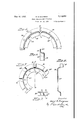
- Figure 1 is a sectional elevation of a clutch mechanism of the multiple disc type produced in conformity with my invention
- Figure 2 is a view in elevation of the hub sleeve l6 and its plate 8. a
- Figure 3 is a fragmentary plan view of one of the two rings of the cushioning unit
- Figure 4 is a sectional view on the line 4-4 of the preceding figure.
- Figure 5 is a fragmentary plan view of the smaller ring of the aforesaid cushioning unit.
- Figure 6 is a sectional view on the line 6'6 of Figure 5, and
- Figure 7 is a sectional view of portions of the two rings, showing the association of their re spective lugs.
- these plates 8 and 9 are rigid with their respective sleeves, as in clutch mechanisms of standard types, they are connected thereto by a yieldable or elastic medium, as rubber, or a rubber composition, whereby the plates will be capable of torsional movement relatively to the sleeves, within predetermined limits, as hereinafter set forth.
- the sleeve l6 embodies a preferably integral flange l6a,-having a serrated or toothed periphery, as at I61), the spacing of the teeth or projections and their dimensions de-' pending upon the duty to which 'the clutch mechanism is to be applied and production or other requirements.
- I provide a surrounding concentric annulus l8 formed with recesses or spaces lBa into which the teeth or projections lBb' of the flange protrude, the width of the recesses or spaces being greater than that of the teeth lfib, to provide for relative and conjoint rotative movement of the annulus and the hub sleeve l6, as and for the purposes hereinafter explained.
- This material which may be rubber or a product of similar characteristics, is a component of a structural element of the clutch mechanism which I shall term the cushioning unit.
- a collar 19 having an offset flange l9a is riveted to the flange I6a of the-sleeve l6, as at 23, and functions as a support for a mass of resilient material, as rubber, indicated at 2!, within which is embedded a series of cooperating non-yieldable elements, certain of which are rigid with the sleeve, while the others are fixed for rotative movement with the annulus la.
- the said elements, in the present showing take the form of circumferentially spaced lugs I91) and 30b, stamped out of the body portions of the rings 20 and 30 and disposed at a right angle thereto, as is clearly shown in Fi'gures' l, 6, and '7.
- the rings 20 and 30 are of different diameters, the smaller 39, embodying a flange 30d offset inwardly of the body portion and apertured at 30c for the reception of the aforesaid rivets23,
- the cushioning unit provides a yieldable or shock-absorbing coupling between the annulus 18, to which the clutch-plate is fixed for co-movement, and the hub sleeve Hi, the deformation of the rubber under load to dissipate therewithin the detrimental forces transmitted to the unit, being controlled to virtually confine it to the direction of torque.
- ! and the interposition of their lugs in the path along which the load forces are distributed contribute to this result, the lugs functioning as abutments upon which the rubber cushions under load.
- a more rugged and better wear-resisting construction is obtainable by conforming to existing practice, and without sacrificing those advantages which are inherent to the latter material.
- the cushioning unit functions to connect the plates and the hub for relative torsional movement, in response to torsional forces which, in the absence of such controlled movement, as has just been described, are communicated to and detrimentally affect the entire power line.
- the elastic material eliminates vibrations that are the product of sudden acceleration or deceleration of the engine or driving members, by providing for the relative movements between the plates and their supporting hub sleeves and acts to cushion the clutch mechanism assembly against mechanical and other shocks to which it is subject in the operation of a vehicle.
- the relative rotative or torsional movement of the plates and the hub sleeves, under the control of the elastic material, is limited to protect the material against rending forces, under overload conditions, by the engagement of the teeth [6b of the sleeve IE (or those of the corresponding sleeve IT) with the end-defining surfaces of the recesses in the cooperating annulus, the hub sleeve and the annulus rotating as a unit when the teeth are engaged in said recesses and establishing a positive connection between the plates and the hub of the mechanism.
- the degree of relative movement of the hub sleeve and associated annulus may be regulated by the size or width of the recesses in proportion to that of the teeth, the latter being freely movable within the recesses in response to the functioning of the elastic material under normal'load conditions.
- a clutch mechanism including a hub memher and a friction plate mounted for relative and conjoint movement, an annulus rigid with said hub member and provided with a toothed periphery, a surrounding ring rigid with said plate formed with recesses into which the teeth of said annulus are entered, the width of said recesses being greater than that of said teeth, whereby said annulus and said ring may function to connect said hub member and said plate only in response to rotative movement of one or the other thereof, and means separate from said annulus and said ring permanently yieldably connecting said hub member and said plate, said latter means including concentric metallic members respectively positively connected to the hub member and plate, one of said concentric members embodying circumferentially spaced abutments, and a mass of elastic material interposed between said concentric members and united thereto and to said abutments by vulcanization, said abutments being surrounded by said elastic material and functioning to limit deformation thereof in the direction of torque effective upon said and to said rings by vulcanization, said elastic material enveloping said lug
Description
May 311, 1938. B. B. BACHMAN 9 9 I 'POWER TRANSMITTING MECHANISM Filed Nov. 24, 1954 2 Sheets-Sheet l Patented May 31, 1938 UNlTED STATES new are in POWER TRANSMITTING MEGHANISM Application November 24, 1934, Serial No. 754,571
2 Claims.
This invention relates generally to power transmitting means and is more particularly directed to improvements in clutch mechanisms employed in connecting a driving element to one which is 5 to be driven therefrom, as, for example, in transmitting the torque from the crank-shaft of an engine in an automotive vehicle to the transmission drive shaft.
While my invention, as will become evident from the description thereof, possesses a wide range of utility in the machine art, as well as in the automotive and other fields, for the purposes of this disclosure, I have elected to treat it more or less specifically, as it may be applied in the construction and operation of motor-vehicles of the conventional design, in which the internal combustion engine is connected, at will, to the shaft of a change-speed gear set by the functioning of a clutch mechanism interposed in the power line, between the driving and driven elements. It will be understood, however, that this is merely illustrative and is not to be construed, in any sense, as a limitation of the scope of my invention.
As is well known, the standard type of clutch mechanism employed in motor-vehicle construction, embodies a plurality of so-called friction plates concentric with the gear-set drive shaft which are urged into frictional engagement by spring means, to coact with the engine fly-wheel 30 for delivering the torque of the engine crankshaft to the gear-set shaft, at the will of the vehicle operator. In these clutch mechanisms, while provision is made for the requisite yieldability of the cooperating elements longitudinally of the gear-set shaft, for moving the friction plates into and out of effective engagement, the entire assembly is subject to those detrimental forces which emanate from the rigid connection of the plates to the gear-set shaft, through their supporting hub splined thereto. Obviously, the torsional strains imposed upon the clutch mechanism, not only as the clutch plates are engaged, but in the acceleration and deceleration of the vehicle, under operating conditions, are communicated to the gear-set and through the propeller shaft to the rear end drive, so that the entire power line is afiected.
In the efforts to overcome the aforementioned disadvantages inherent to the standard types of 5 motor-vehicle clutch mechanisms, various expedients have been proposed, as, for example, by connecting the plates to the clutch hub, through the medium of a yieldable or elastic material, as rubber. However, none of these attempts to solve the problem has been entirely successful, for one reason or another. While the advantages of utilizing an elastic material to obtain the requisite angular yieldability between the clutch plates and the hub of the mechanism, for neutralizing the eifects of the torsional strains, are recognized, 5 no satisfactory method has been evolved for confining the rubber and protecting it against excessive loads, so that it will perform its intended function, without a degree of deformation that soon renders it susceptible to disintegration, with 10 a consequent rapid deterioration of the entire clutch assembly.
Therefore, it is the primary object of this invention to provide means for utilizing rubber or other elastic material for connecting the frictionl5 ally engageable surfaces, as the plates, of a clutch mechanism with the hub member of the assembly, whereby the previously described disadvantages that are inherent to existing constructions of the kind, will be eliminated in a simple, practical and economical manner.
Another important object of this invention is to provide a clutch mechanism, as aforesaid, where'- in the frictionally engageable surfaces are connected to the clutch hub by an elastic material, which will be more efficient in operation and more highly resistant to wear than existing constructions, embodying a yieldable connection between the plates and the hub, this objective being attained by a method and means of controlling the deformation of the elastic material to the path of rotation of the interconnected elements of the mechanism, thus not only preserving the resiliency of the material for a long period, but entirely eliminating the tendency to disintegration that is a direct result of uncontrolled deformation and the consequent loss of resiliency.
A further object of my invention is to provide a clutch mechanism, possessing the herein set forth characteristics and advantages, wherein I employ means adapted to coact with the elastic connecting material, between the frictionally engageable surfaces and the clutch hub, under predetermined conditions in the functioning of the clutch mechanism to protect the elastic material against the imposition of excessive loads thereon, and the resultant impairment of its structure, such means, in conjunction with the control of the deformation of the material, making it possible to produce a clutch mechanism of the shockabsorbing type that will respond to the demands for greater durability of the assembly as a unit and less frequent overhauls and adjustments,
More specifically, it is the object of this invention to provide a. clutch mechanism for motorvehicles for coupling the transmission drive shaft to the engine fly-wheel, wherein the torsional strains and other forces which detrimentally affect the clutch mechanism and the units of the entire power line to which they are communicated therethrough, in structures of the conventional design, are dissipated or absorbed within the clutch mechanism itself, by the controlled deformation of a resilient driving connection between the clutch plates and the hub splined to the transmission drive shaft in response to the initiation of such forces, the connection being relieved under excessive load conditions for the maintenance of its shock-absorbing effectiveness.
Other objectives, such as the elimination or dampening of noises incidental to looseness of parts, through wear and increased smoothness in operation, will become manifest as the description proceeds and I would have it clearly understood that I reserve unto myself all rights to the full range of equivalents, both in structure and in use, to which I may be entitled under my invention, in its broadest aspect,
In the accompanying drawings, I have shown a preferred embodiment of my invention in a clutch mechanism of a conventional or standard design of the so-called plate or disc-type. Obviously my invention may take other forms and may be incorporated in other clutch structures, within the scope of my invention, as defined by the appended claims.- a
In the drawings: 7
Figure 1 is a sectional elevation of a clutch mechanism of the multiple disc type produced in conformity with my invention,
Figure 2 is a view in elevation of the hub sleeve l6 and its plate 8. a
Figure 3 is a fragmentary plan view of one of the two rings of the cushioning unit,
Figure 4 is a sectional view on the line 4-4 of the preceding figure.
Figure 5 is a fragmentary plan view of the smaller ring of the aforesaid cushioning unit. I
Figure 6 is a sectional view on the line 6'6 of Figure 5, and
Figure 7 is a sectional view of portions of the two rings, showing the association of their re spective lugs.
Referring now to the drawings in detail, in which like characters of reference are employed to designate similar parts in the several views, the clutch mechanism, which is enclosed. in the usual housing 1, embodies the customary clutch plates 8 and 9, provided with facings Ba-8b and 9a9b and the coacting pressure plates 10 and H which are interconnected inwardly of their peripheries by suitable pins and cooperating springs (not shown) in radially spaced relation, for relative movement in a path parallel to the axis of the transmission drive shaft l2, mounted at its forward end in the usual pilot bearing H3, in response to the actuation of the clutch mechanism releasing means, generally indicated at l3, for rendering the clutch non-effective and in a counter direction to permit the aforesaid interconnecting springs to function to urge the clutch and pressure plates into close frictional associa= tion with each other and with the face of the fly-wheel l4 bolted, as at [5:1, to the customary flange 15b of the engine crank-shaft [5 (not shown), through the medium of the facing 8a of the clutch plate 8, to transmit the driving torque from the engine shaft to the transmission drive shaft. I
The components of the clutch mechanism just mission drive shaft I2, for movement longitudinally thereof, whereby the clutch and pressure plates may be actuated into and out of engagement, the clutch plate 8, as in existing clutch mechanisms being carried by the sleeve [6 while its counterpart 9 is supported from the sleeve l1. However, instead of these plates 8 and 9 being rigid with their respective sleeves, as in clutch mechanisms of standard types, they are connected thereto by a yieldable or elastic medium, as rubber, or a rubber composition, whereby the plates will be capable of torsional movement relatively to the sleeves, within predetermined limits, as hereinafter set forth.
Since the sleeves l6 and H and the manner in which the clutch plates 8 and 9 are respectively connected thereto for limited relative torsional or rotative movement, are identical, it is believed. that a detailed description of the sleeve l6 and the interconnection of the plate 8 therewith, will suffice for the purposes of this disclosure.
As will be observed, the sleeve l6 embodies a preferably integral flange l6a,-having a serrated or toothed periphery, as at I61), the spacing of the teeth or projections and their dimensions de-' pending upon the duty to which 'the clutch mechanism is to be applied and production or other requirements. In association with said flange lfia, I provide a surrounding concentric annulus l8 formed with recesses or spaces lBa into which the teeth or projections lBb' of the flange protrude, the width of the recesses or spaces being greater than that of the teeth lfib, to provide for relative and conjoint rotative movement of the annulus and the hub sleeve l6, as and for the purposes hereinafter explained.
The sleeve l6, through its aforesaid flange lGa, is also connected to the annulus l8, independently of the connection which may be established between these parts by the interengagement of the coacting surfaces of the teeth and recesses thereof, under predetermined conditions in the functioning of the clutch mechanism, by a mass of resilient or elastic material. This material, which may be rubber or a product of similar characteristics, is a component of a structural element of the clutch mechanism which I shall term the cushioning unit.
In the formation of this cushioning-unit, a collar 19 having an offset flange l9a is riveted to the flange I6a of the-sleeve l6, as at 23, and functions as a support for a mass of resilient material, as rubber, indicated at 2!, within which is embedded a series of cooperating non-yieldable elements, certain of which are rigid with the sleeve, while the others are fixed for rotative movement with the annulus la. The said elements, in the present showing take the form of circumferentially spaced lugs I91) and 30b, stamped out of the body portions of the rings 20 and 30 and disposed at a right angle thereto, as is clearly shown in Fi'gures' l, 6, and '7. As
will be noted, especially from Figuresi3 and 5,
the rings 20 and 30 are of different diameters, the smaller 39, embodying a flange 30d offset inwardly of the body portion and apertured at 30c for the reception of the aforesaid rivets23,
which function to anchor the collar I9 to the sleeve flange [6a, the cut-outs 3|, whereby the lugs 3% are formed being in the outer periphery of the ring body. In the larger ring, as will be observed, the cutouts for the formation of its lugs iSb are spaced along its inner periphery, this ring, likewise, being provided with an offset attaching flange 20a, apertured at 200, for the reception of the rivets 22, whereby it is made rigid with the annulus [8, these rivets also serving to secure the clutch plate 8 to said annulus for movement therewith.
When the rings 28 and 30 are assembled in concentric relation on the sleeve l6 and annulus [8, respectively, as described, their lugs Nb and 30b will be oppositely disposed in laterally spaced relation, as shown in Figure '7, or in any suitable variation of such arrangement, it being evident that the resilient material 2|, in which the lugs of the two rings are embedded completely encloses them and fills the spaces therebetween, so that, in effect, the rings 20 and 3!] and the collar IS, with the resilient material, which is united to said rings and collar by an appropriate vulcanization process form an integral structure, in which the two rings are relatively rotatable, within the elastic limits of the rubber within which their lugs are confined, as hereinafter pointed out.
From the construction described, it will be apparent that the cushioning unit provides a yieldable or shock-absorbing coupling between the annulus 18, to which the clutch-plate is fixed for co-movement, and the hub sleeve Hi, the deformation of the rubber under load to dissipate therewithin the detrimental forces transmitted to the unit, being controlled to virtually confine it to the direction of torque. It will be obvious that the formation of the rings 20 and 3|! and the interposition of their lugs in the path along which the load forces are distributed contribute to this result, the lugs functioning as abutments upon which the rubber cushions under load. Also, by the arrangement of the cooperating metallic components of the cushioning unit and their union with the elastic material, a more rugged and better wear-resisting construction is obtainable by conforming to existing practice, and without sacrificing those advantages which are inherent to the latter material.
In operation, the clutch and pressure plates of the two units of the mechanism are urged into frictional surface engagement, with the facing 8a of the plate 8 contacting the face of the flywheel M, as heretofore described, under the control of the operator, through the medium of the shifting means, indicated at l3. Now, as the plates are pressed into close association with each other and frictionally coupled to the flywheel, the efiort will be transmitted from the plates, through the cushioning unit to the hub sleeves and drive shaft of the transmission, the elastic material, cushioning upon the lugs 59b and b in the path of rotation of the clutch mechanism elements, to provide for the requisite relative torsional or rotative movement of the plates and hub sleeves, in a degree determined by the torsional forces developed in the application of the driving torque to the driven elements of the power line. In other words, the cushioning unit functions to connect the plates and the hub for relative torsional movement, in response to torsional forces which, in the absence of such controlled movement, as has just been described, are communicated to and detrimentally affect the entire power line. Obviously, the elastic material eliminates vibrations that are the product of sudden acceleration or deceleration of the engine or driving members, by providing for the relative movements between the plates and their supporting hub sleeves and acts to cushion the clutch mechanism assembly against mechanical and other shocks to which it is subject in the operation of a vehicle.' Further, by virtually confining the rubber, for deformation only within itself, it will be manifest that its capacity for absorption and dissipation of detrimental forces transmitted thereto will be greater than where it may yield in a multiplicity of directions or zones.
As will be understood, the relative rotative or torsional movement of the plates and the hub sleeves, under the control of the elastic material, is limited to protect the material against rending forces, under overload conditions, by the engagement of the teeth [6b of the sleeve IE (or those of the corresponding sleeve IT) with the end-defining surfaces of the recesses in the cooperating annulus, the hub sleeve and the annulus rotating as a unit when the teeth are engaged in said recesses and establishing a positive connection between the plates and the hub of the mechanism. The degree of relative movement of the hub sleeve and associated annulus, as will be evident, may be regulated by the size or width of the recesses in proportion to that of the teeth, the latter being freely movable within the recesses in response to the functioning of the elastic material under normal'load conditions.
While I have described my invention with reference to the specific showing, it will be clear that various departures from the structure illustrated may be made and that the method and means employed for connecting the plates for movement relatively to their supporting hub may be adapted to other types of clutch mechanisms or power transmitting media, within the spirit and scope of this disclosure.
I claim:
1. A clutch mechanism including a hub memher and a friction plate mounted for relative and conjoint movement, an annulus rigid with said hub member and provided with a toothed periphery, a surrounding ring rigid with said plate formed with recesses into which the teeth of said annulus are entered, the width of said recesses being greater than that of said teeth, whereby said annulus and said ring may function to connect said hub member and said plate only in response to rotative movement of one or the other thereof, and means separate from said annulus and said ring permanently yieldably connecting said hub member and said plate, said latter means including concentric metallic members respectively positively connected to the hub member and plate, one of said concentric members embodying circumferentially spaced abutments, and a mass of elastic material interposed between said concentric members and united thereto and to said abutments by vulcanization, said abutments being surrounded by said elastic material and functioning to limit deformation thereof in the direction of torque effective upon said and to said rings by vulcanization, said elastic material enveloping said lugs and forming a cushion therebetween and means on said hub member and said annulus to render said annulus and said hub member capable of limited relative rotative movement under the control of said elastic material and to interlock said hub memher and said annulus for conjoint rotative movement upon the completion of their relative limited rotative movement.
BENJAMIN B. BACHMAN.
Priority Applications (1)
| Application Number | Priority Date | Filing Date | Title |
|---|---|---|---|
| US754571A US2118913A (en) | 1934-11-24 | 1934-11-24 | Power transmitting mechanism |
Applications Claiming Priority (1)
| Application Number | Priority Date | Filing Date | Title |
|---|---|---|---|
| US754571A US2118913A (en) | 1934-11-24 | 1934-11-24 | Power transmitting mechanism |
Publications (1)
| Publication Number | Publication Date |
|---|---|
| US2118913A true US2118913A (en) | 1938-05-31 |
Family
ID=25035381
Family Applications (1)
| Application Number | Title | Priority Date | Filing Date |
|---|---|---|---|
| US754571A Expired - Lifetime US2118913A (en) | 1934-11-24 | 1934-11-24 | Power transmitting mechanism |
Country Status (1)
| Country | Link |
|---|---|
| US (1) | US2118913A (en) |
Cited By (10)
| Publication number | Priority date | Publication date | Assignee | Title |
|---|---|---|---|---|
| DE919335C (en) * | 1951-10-25 | 1954-10-18 | Pius Buchegger | Friction disc clutch for motor vehicles |
| DE1019186B (en) * | 1954-11-05 | 1957-11-07 | Fichtel & Sachs Ag | Friction disc clutch, especially for motor vehicles |
| US2892646A (en) * | 1954-07-26 | 1959-06-30 | Jabsco Pump Co | Impeller-shaft connection |
| US4485908A (en) * | 1982-06-09 | 1984-12-04 | Borg-Warner Corporation | Vibration damper with variable rate springs and damping friction |
| US4763767A (en) * | 1985-06-14 | 1988-08-16 | Valeo | Torsional damper device |
| US5653144A (en) * | 1993-02-09 | 1997-08-05 | Fenelon; Paul J. | Stress dissipation apparatus |
| US5692410A (en) * | 1993-02-09 | 1997-12-02 | Fenelon; Paul J. | Rotatable apparatus having a stress dissipation structure |
| US5956998A (en) * | 1996-06-06 | 1999-09-28 | Fenelon; Paul J. | Stress reduction gear and apparatus using same |
| US20040261273A1 (en) * | 2003-06-24 | 2004-12-30 | Griep David B. | Drive mechanism and power tool |
| US20050016001A1 (en) * | 2003-06-24 | 2005-01-27 | Milwaukee Electric Tool Corporation | Drive mechanism and power tool |
-
1934
- 1934-11-24 US US754571A patent/US2118913A/en not_active Expired - Lifetime
Cited By (11)
| Publication number | Priority date | Publication date | Assignee | Title |
|---|---|---|---|---|
| DE919335C (en) * | 1951-10-25 | 1954-10-18 | Pius Buchegger | Friction disc clutch for motor vehicles |
| US2892646A (en) * | 1954-07-26 | 1959-06-30 | Jabsco Pump Co | Impeller-shaft connection |
| DE1019186B (en) * | 1954-11-05 | 1957-11-07 | Fichtel & Sachs Ag | Friction disc clutch, especially for motor vehicles |
| US4485908A (en) * | 1982-06-09 | 1984-12-04 | Borg-Warner Corporation | Vibration damper with variable rate springs and damping friction |
| US4763767A (en) * | 1985-06-14 | 1988-08-16 | Valeo | Torsional damper device |
| US5653144A (en) * | 1993-02-09 | 1997-08-05 | Fenelon; Paul J. | Stress dissipation apparatus |
| US5692410A (en) * | 1993-02-09 | 1997-12-02 | Fenelon; Paul J. | Rotatable apparatus having a stress dissipation structure |
| US5943913A (en) * | 1993-02-09 | 1999-08-31 | Fenelon; Paul J. | Rotatable apparatus having a stress dissipation structure |
| US5956998A (en) * | 1996-06-06 | 1999-09-28 | Fenelon; Paul J. | Stress reduction gear and apparatus using same |
| US20040261273A1 (en) * | 2003-06-24 | 2004-12-30 | Griep David B. | Drive mechanism and power tool |
| US20050016001A1 (en) * | 2003-06-24 | 2005-01-27 | Milwaukee Electric Tool Corporation | Drive mechanism and power tool |
Similar Documents
| Publication | Publication Date | Title |
|---|---|---|
| US3101600A (en) | Vibration dampeners | |
| US4613029A (en) | Torsion damping device for an automobile clutch friction disc | |
| US2745268A (en) | Clutch driven plate | |
| US3556273A (en) | Clutch disc with vibration dampeners in series | |
| US2375909A (en) | Clutch | |
| US4095683A (en) | Diaphragm spring clutch | |
| US2158244A (en) | Clutch plate | |
| US2674863A (en) | Friction clutch plate | |
| US2885047A (en) | Clutch assembly | |
| US2118913A (en) | Power transmitting mechanism | |
| US3514974A (en) | Noise prevention device in torsional vibration | |
| US5169357A (en) | Torsion damping device, in particular for a clutch friction disc for a motor vehicle | |
| US2539387A (en) | Vehicle wheel drive | |
| US3331262A (en) | Differential gearing mechanism incorporating therein a resiliently preloaded clutch | |
| US3557923A (en) | Multiple disc clutch with cushioned engagement | |
| US2097627A (en) | Vibration dampener | |
| US2171908A (en) | Clutch | |
| US3236347A (en) | Friction clutch | |
| US3657935A (en) | Differential transmission | |
| US1967322A (en) | Clutch | |
| US2672226A (en) | Centrifugal clutch | |
| US4016962A (en) | Vibration resistant mechanical clutch | |
| US2899038A (en) | wellauer | |
| US2776556A (en) | Devices for the transmission of power from the engine of a motor vehicle to the driven wheels thereof | |
| US1753365A (en) | Flywheel |