US2091663A - Ultra high frequency transmitter - Google Patents
Ultra high frequency transmitter Download PDFInfo
- Publication number
- US2091663A US2091663A US67577A US6757736A US2091663A US 2091663 A US2091663 A US 2091663A US 67577 A US67577 A US 67577A US 6757736 A US6757736 A US 6757736A US 2091663 A US2091663 A US 2091663A
- Authority
- US
- United States
- Prior art keywords
- condenser
- capacitor
- high frequency
- ultra high
- frequency transmitter
- Prior art date
- Legal status (The legal status is an assumption and is not a legal conclusion. Google has not performed a legal analysis and makes no representation as to the accuracy of the status listed.)
- Expired - Lifetime
Links
Images
Classifications
-
- H—ELECTRICITY
- H03—ELECTRONIC CIRCUITRY
- H03C—MODULATION
- H03C5/00—Amplitude modulation and angle modulation produced simultaneously or at will by the same modulating signal
Definitions
- This invention relates to modulated: carrier wave transmitters and more particularly to modulated carrier wave transmitters of the kind comprising oscillatorsoperating upon the so-called Barkhausen-Kurz or Gill-Morell principle, i. e.
- a thermionic oscillator whose grid is maintained at a positive potential relative to the cathode and anode thereof so that electrons overshoot the grid, are retarded in the grid-anode space, change direction, return through the grid, change direction again and oscillate back and forth through the griduntil finally collected thereby.
- I Barkhausen-Kurz or Gill-Morell and like oscillators are commonly employed for the generation of, veryhigh frequency oscillations, e. g., for very short wave radio transmission.
- the usual practice is to take the oscillatory energy from the oscillating valve. or valves by means of a Lecher wire system or other tuned circuit and thus to transfer the's aid energy to the radiating dipole or other utilization device.
- Modulation of the oscillatory energy is usually effected by varying the oscillator anode or grid potential in accordance with the modulating impulses.
- One defect of the heretofore known arrangements is that variation in anode or grid potential (for modulation purposes) tends to'change the frequency generated since, as is well known, the frequency of the oscillations generated by a Barkhausen-Kurz or Gill-Morell oscillator depends upon the periodicity of the electron swing about the grid, which in turn depends largely upon the potentials applied.
- the object of the present invention is to avoid the above mentioned defect and to provide an improved modulator arrangement for a Barkhausen-Kurz or Gill-Morell type of oscillator wherein the frequency generated shall not be appreciably, if at all, affected by the applied modulating waves.
- a Lecher wire or other tuned circuit system associated with a Barkhausen-Kurz or Gill-Morell or like type of oscillator is shunted by a variable condenser and means are provided for varying the capacity of this condenser in dependence upon modulating potentials. In this way modulation is effected without substantially affecting the potentials ap-. plied to the oscillator electrodes. It will be appreciated that the effect of varying the shunt condenser in capacity in accordance with the modulation will be effectively to lengthen or shorten electrically the tuned. circuit or other Lecher wire system.
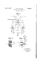
- Fig. 2 shows a detail of construction of one arrangement of a variable capacitor for use in the circuit of Fig. l, this'capacitor beingmagnetically controlled by modulating potentials; and Fig. 3 shows a different arrangement whereby the same capacitor of Fig. 1 may be varied by means of a dynamic actuator under control of modulating potentials.
- 7 Referring to Fig. 1, I show a Barkhausen-Kurz or Gill-Morell arrangement comprising two -;tri-
- odes I, 2 having their grids 3, 4, connected to the wires 5, 6, of a Lecher wire system, a nodal point 1 upon this system being connected to a suitable source 8 of positive potential so that the grids receive the necessary positive potentialthrough the tuned Lecher wire grid system.
- the anodes 9, I0, of the two valves are connected together through a choke II, the center point I2 of which is connected either to the cathode point or to a point of small negative or positive potential.
- Each anode is also connected to one wire I3 or Id of a pair of Lecher wires which constitute a tuned output circuit each wire of the pair being connected to one half of a radiating dipole I5;
- the two cathodes IB, H are each earthed at one end-and each is connectedatthe other end to one wire I8 or I9 of a tuned Lecher wire system whereby the cathode circuit also is tuned.
- Shunted between the wires of the anode Lecher wire system is a condenser 20 whose capacity is varied in dependence upon modulating potentials and modulation is efiected by varying this capacity. I, therefore, prefer to call this condenser 20 a modulatory capacitor.
- variable condenser 20 of Fig. 1 is constituted by the capacity between two electrode plates 2
- modulating potentials from a source not shown
- the coils 24 theeffective magnetic intensity thereof will vary as the magnetism due to the coils aids or opposes the permanent magnetism.
- the diaphragm-electrode 22 will move relative to the other electrode 2I of the condenser course, insulated from one another and the dielectric of the condenser thereby constituted may be air or some suitable solid di-electric as design requirements may dictate. Solid di-electric is indicated by the broken line.
- I r Fig. 3 shows another form of condenser suitable for use as the condenser 20 of Fig. 1.
- one (25) of two electrodes 25, 26, is fixed and translating modulating energy into mechanical vibrations and subjecting at least one of the electhe other (26) is mechanically attached, to ;the moving coil 21 of an electro-dynamic system resembling the electro-dynamics'ystemof a'moving coil loud-speaker or telephone; for example, as
- the moving electrode 26 may be attached through a suitable pivoted driving lever-28 and cone 29 to a cylindrical coil 21 interposed in the annular gap of a permanent or electro-magnet 30, modulating potentials from a source (not shown) being passedthrough this coil 21.
- variable condenser (not illustrated) which was experimentally employed in carrying out this invention
- the said condenser comprised two plates, one of which 30 was the diaphragm of an ordinary electrodynamic telephone ear piece and the other of which was constituted by a piece of metal foil about 2 ems. in area, the dielectric being constituted by a sheet of insulating material having a specific inductive capacity of about 2; The foil was stuck on the said sheet and the normal (unmodulated) capacity thus obtained was about '7 micro-micro-farads.
- An oscillatory system of the Barkhausen- Kurz type comprising a pair of electron discharge tubes having their output circuits disposed in a' push-pull arrangement, a variable capacitor shunted by an inductance connected across the output circuits of the respective tubes, a dipole antenna system havingeachradiating arm thereof connected to its respective side of the pushpull output circuit arrangement, and'means operable under control of modulating energy for varying the effective value of said capacitor.
- An oscillatory system comprising a pair of triode electron discharge tubes having their output circuits disposed in a push-pull arrangement
- means for polarizing the grids of said tubes highly? positive with respect to the cathodes means :for .caus'ingthe plates .ofsaid' tubes to actiasretard:electrodes, a capacitor'having one of its-electrodes constituted by a magnetically controlled diaphragm, said capacitor being shunted-byian inductance and-connected across the output circuits of the respective tubes, and a dipole antenna system having each radiating arm thereof connected to its respective side of the push pull arrangement.
- 551m oscillatory system comprising a pair of triode electron discharge tubes having their output circuits disposed in apush-pull arrangement, means for polarizing the grids of said tubes highly positive with respect to the cathodes, means for causing-the plates of said tubes to act as retard electrodes, a capacitor shunted by an inductance and connected across the output circuits of'the respective tubes, a dipole antenna system having each radiating arm thereof connected to its respective side of the push-pull arrangement, and means including an e'lectro magnetic structure' and a coil movable in the field.” thereof and mechanically linked to one of the electrodes of said capacitor for varying the capacitance thereof, thereby to modulate the output energy of said push-pull arrangement.
Description
Aug. 31, 1937. H. w. w. WALDEN ULTRA HIGH FREQUENCY TRANSMITTER Filed March 7, 1936 Modalatag Cafa'Ct i0/\1\Z 1 INVENTOR HARRY W144 WALOEA/ 4 gig ATTO R N EY Patented Aug. 31, 1937 PATENT orrlcsf ULTRA HIGH FREQUENCY TRANSMITTER Harry, William land, assignor Waterman Walden, London, Engto Radio Corporation of America, a'corporation of Delaware Application March 7,
Inv Great Britain 1936, Serial No. 67,577
March 11, 1935 s olaims. (01. 250-17) This invention relates to modulated: carrier wave transmitters and more particularly to modulated carrier wave transmitters of the kind comprising oscillatorsoperating upon the so-called Barkhausen-Kurz or Gill-Morell principle, i. e.
of the kind comprising a thermionic oscillator whose grid is maintained at a positive potential relative to the cathode and anode thereof so that electrons overshoot the grid, are retarded in the grid-anode space, change direction, return through the grid, change direction again and oscillate back and forth through the griduntil finally collected thereby. I Barkhausen-Kurz or Gill-Morell and like oscillators are commonly employed for the generation of, veryhigh frequency oscillations, e. g., for very short wave radio transmission. The usual practice is to take the oscillatory energy from the oscillating valve. or valves by means of a Lecher wire system or other tuned circuit and thus to transfer the's aid energy to the radiating dipole or other utilization device. Modulation of the oscillatory energy is usually effected by varying the oscillator anode or grid potential in accordance with the modulating impulses. One defect of the heretofore known arrangements is that variation in anode or grid potential (for modulation purposes) tends to'change the frequency generated since, as is well known, the frequency of the oscillations generated by a Barkhausen-Kurz or Gill-Morell oscillator depends upon the periodicity of the electron swing about the grid, which in turn depends largely upon the potentials applied.
The object of the present invention is to avoid the above mentioned defect and to provide an improved modulator arrangement for a Barkhausen-Kurz or Gill-Morell type of oscillator wherein the frequency generated shall not be appreciably, if at all, affected by the applied modulating waves.
According to this invention a Lecher wire or other tuned circuit system associated with a Barkhausen-Kurz or Gill-Morell or like type of oscillator is shunted by a variable condenser and means are provided for varying the capacity of this condenser in dependence upon modulating potentials. In this way modulation is effected without substantially affecting the potentials ap-. plied to the oscillator electrodes. It will be appreciated that the effect of varying the shunt condenser in capacity in accordance with the modulation will be effectively to lengthen or shorten electrically the tuned. circuit or other Lecher wire system.
The invention is illustrated in ing drawing, in which Figure 1 shows diagrammatically one embo'di-- ment;
the accompany- Fig. 2 shows a detail of construction of one arrangement of a variable capacitor for use in the circuit of Fig. l, this'capacitor beingmagnetically controlled by modulating potentials; and Fig. 3 shows a different arrangement whereby the same capacitor of Fig. 1 may be varied by means of a dynamic actuator under control of modulating potentials. 7 Referring to Fig. 1, I show a Barkhausen-Kurz or Gill-Morell arrangement comprising two -;tri-
odes I, 2, having their grids 3, 4, connected to the wires 5, 6, of a Lecher wire system, a nodal point 1 upon this system being connected to a suitable source 8 of positive potential so that the grids receive the necessary positive potentialthrough the tuned Lecher wire grid system. The anodes 9, I0, of the two valves are connected together through a choke II, the center point I2 of which is connected either to the cathode point or to a point of small negative or positive potential. Each anode is also connected to one wire I3 or Id of a pair of Lecher wires which constitute a tuned output circuit each wire of the pair being connected to one half of a radiating dipole I5; The two cathodes IB, H, are each earthed at one end-and each is connectedatthe other end to one wire I8 or I9 of a tuned Lecher wire system whereby the cathode circuit also is tuned. Shunted between the wires of the anode Lecher wire system is a condenser 20 whose capacity is varied in dependence upon modulating potentials and modulation is efiected by varying this capacity. I, therefore, prefer to call this condenser 20 a modulatory capacitor.
Various forms of variable capacity arrangements can be employed in carrying out this invention. For example, in one convenient form illustrated in Fig. 2 the variable condenser 20 of Fig. 1 is constituted by the capacity between two electrode plates 2|, 22, one (2|) of Which is fixed and the other (22) of which acts as a diaphragm with respect to a magnetic system consisting of a permanent magnet 23 having coils 24 wound thereon the poles of the magnet 23 being adjacent the diaphragm plate 22. When modulating potentials (from a source not shown) are applied to the coils 24 theeffective magnetic intensity thereof will vary as the magnetism due to the coils aids or opposes the permanent magnetism. As a result the diaphragm-electrode 22 will move relative to the other electrode 2I of the condenser course, insulated from one another and the dielectric of the condenser thereby constituted may be air or some suitable solid di-electric as design requirements may dictate. Solid di-electric is indicated by the broken line. I r Fig. 3 shows another form of condenser suitable for use as the condenser 20 of Fig. 1. Here one (25) of two electrodes 25, 26, is fixed and translating modulating energy into mechanical vibrations and subjecting at least one of the electhe other (26) is mechanically attached, to ;the moving coil 21 of an electro-dynamic system resembling the electro-dynamics'ystemof a'moving coil loud-speaker or telephone; for example, as
shown, the moving electrode 26 may be attached through a suitable pivoted driving lever-28 and cone 29 to a cylindrical coil 21 interposed in the annular gap of a permanent or electro-magnet 30, modulating potentials from a source (not shown) being passedthrough this coil 21. The
coil will accordingly vibrate electroedynamically just as does the moving coil of an electro-dynamic telephone and in this Way the capacity of the condenser 25-46 will be varied.
In an actual example of variable condenser (not illustrated) which was experimentally employed in carrying out this invention the said condenser comprised two plates, one of which 30 was the diaphragm of an ordinary electrodynamic telephone ear piece and the other of which was constituted by a piece of metal foil about 2 ems. in area, the dielectric being constituted by a sheet of insulating material having a specific inductive capacity of about 2; The foil was stuck on the said sheet and the normal (unmodulated) capacity thus obtained was about '7 micro-micro-farads.
I claim:
40 1. An oscillatory system of the Barkhausen- Kurz type comprising a pair of electron discharge tubes having their output circuits disposed in a' push-pull arrangement, a variable capacitor shunted by an inductance connected across the output circuits of the respective tubes, a dipole antenna system havingeachradiating arm thereof connected to its respective side of the pushpull output circuit arrangement, and'means operable under control of modulating energy for varying the effective value of said capacitor.
2. A system in accordance with claim I and having a Lecher-wire system interposed between the anodes of said tubes and the arms of said dipole antenna system.
3. The method of modulating the output en ergy from a Barkhausen-Kurz oscillator of the type having two electron discharge tubes Whose anodes are interconnected by a tuned circuit consisting of an inductance in shunt with a variable capacitor, which method comprises the steps of trodes of said capacitor to said vibrations thereby to vary the thickness of the dielectric between the capacitor electrodes and hence to vary the resonant conditions of said tuned circuit.
4. An oscillatory system comprising a pair of triode electron discharge tubes having their output circuits disposed in a push-pull arrangement,
means for polarizing the grids of said tubes highly? positive with respect to the cathodes, means :for .caus'ingthe plates .ofsaid' tubes to actiasretard:electrodes, a capacitor'having one of its-electrodes constituted by a magnetically controlled diaphragm, said capacitor being shunted-byian inductance and-connected across the output circuits of the respective tubes, and a dipole antenna system having each radiating arm thereof connected to its respective side of the push pull arrangement.
. 551m oscillatory system comprising a pair of triode electron discharge tubes having their output circuits disposed in apush-pull arrangement, means for polarizing the grids of said tubes highly positive with respect to the cathodes, means for causing-the plates of said tubes to act as retard electrodes, a capacitor shunted by an inductance and connected across the output circuits of'the respective tubes, a dipole antenna system having each radiating arm thereof connected to its respective side of the push-pull arrangement, and means including an e'lectro magnetic structure' and a coil movable in the field." thereof and mechanically linked to one of the electrodes of said capacitor for varying the capacitance thereof, thereby to modulate the output energy of said push-pull arrangement.
. -HA RRY- WILLIAM WATERMAN WALDEN.
Applications Claiming Priority (1)
| Application Number | Priority Date | Filing Date | Title |
|---|---|---|---|
| GB7567/35A GB451056A (en) | 1935-03-11 | 1935-03-11 | Improvements in or relating to modulated carrier wave transmitters |
Publications (1)
| Publication Number | Publication Date |
|---|---|
| US2091663A true US2091663A (en) | 1937-08-31 |
Family
ID=9835593
Family Applications (1)
| Application Number | Title | Priority Date | Filing Date |
|---|---|---|---|
| US67577A Expired - Lifetime US2091663A (en) | 1935-03-11 | 1936-03-07 | Ultra high frequency transmitter |
Country Status (2)
| Country | Link |
|---|---|
| US (1) | US2091663A (en) |
| GB (1) | GB451056A (en) |
Cited By (2)
| Publication number | Priority date | Publication date | Assignee | Title |
|---|---|---|---|---|
| US2588513A (en) * | 1949-06-10 | 1952-03-11 | Rca Corp | Electrostatic high-voltage generator |
| US4593412A (en) * | 1984-05-21 | 1986-06-03 | Multi-Elmac Company | Integrated oscillator antenna for low power, low harmonic radiation |
-
1935
- 1935-03-11 GB GB7567/35A patent/GB451056A/en not_active Expired
-
1936
- 1936-03-07 US US67577A patent/US2091663A/en not_active Expired - Lifetime
Cited By (2)
| Publication number | Priority date | Publication date | Assignee | Title |
|---|---|---|---|---|
| US2588513A (en) * | 1949-06-10 | 1952-03-11 | Rca Corp | Electrostatic high-voltage generator |
| US4593412A (en) * | 1984-05-21 | 1986-06-03 | Multi-Elmac Company | Integrated oscillator antenna for low power, low harmonic radiation |
Also Published As
| Publication number | Publication date |
|---|---|
| GB451056A (en) | 1936-07-29 |
Similar Documents
| Publication | Publication Date | Title |
|---|---|---|
| US2476162A (en) | High-frequency apparatus | |
| US2293151A (en) | Resonant cavity device | |
| US2092762A (en) | Variable condenser for modulation | |
| US2243202A (en) | Circuit for automatic frequency control | |
| US2091663A (en) | Ultra high frequency transmitter | |
| US2311491A (en) | Radio-acoustic apparatus | |
| US2288214A (en) | Radio system | |
| US2348585A (en) | Modulation system | |
| US2122495A (en) | Magnetron oscillator | |
| US2092069A (en) | Ultra-short wave radio system | |
| US2108830A (en) | Electron discharge apparatus | |
| US1615645A (en) | Combined wireless sending and receiving system | |
| US2247234A (en) | Electron beam tube circuits | |
| US1985683A (en) | Photo-oscillator-modulator system | |
| US2209541A (en) | Modulation system | |
| US2141292A (en) | Radio receiver | |
| US2142186A (en) | Magnetron modulation method | |
| GB483839A (en) | Improvements in or relating to magnetron electron discharge devices and arrangementsincorporating the same | |
| US1990216A (en) | Control of high frequency generators | |
| US2113225A (en) | Frequency controlled electronic oscillator | |
| US2219745A (en) | Magnetron modulator | |
| US2447492A (en) | Timing modulation | |
| US2127486A (en) | Phase modulation | |
| US2511106A (en) | Gas-filled cavity resonator | |
| US1901112A (en) | Signal transmitting means |