US20140327411A1 - Power factor correction algorithm for arbitrary input waveform - Google Patents
Power factor correction algorithm for arbitrary input waveform Download PDFInfo
- Publication number
- US20140327411A1 US20140327411A1 US13/887,210 US201313887210A US2014327411A1 US 20140327411 A1 US20140327411 A1 US 20140327411A1 US 201313887210 A US201313887210 A US 201313887210A US 2014327411 A1 US2014327411 A1 US 2014327411A1
- Authority
- US
- United States
- Prior art keywords
- input
- pfc
- circuit
- factor correction
- power factor
- Prior art date
- Legal status (The legal status is an assumption and is not a legal conclusion. Google has not performed a legal analysis and makes no representation as to the accuracy of the status listed.)
- Granted
Links
Images

Classifications
-
- H—ELECTRICITY
- H02—GENERATION; CONVERSION OR DISTRIBUTION OF ELECTRIC POWER
- H02M—APPARATUS FOR CONVERSION BETWEEN AC AND AC, BETWEEN AC AND DC, OR BETWEEN DC AND DC, AND FOR USE WITH MAINS OR SIMILAR POWER SUPPLY SYSTEMS; CONVERSION OF DC OR AC INPUT POWER INTO SURGE OUTPUT POWER; CONTROL OR REGULATION THEREOF
- H02M1/00—Details of apparatus for conversion
- H02M1/42—Circuits or arrangements for compensating for or adjusting power factor in converters or inverters
- H02M1/4208—Arrangements for improving power factor of AC input
- H02M1/4225—Arrangements for improving power factor of AC input using a non-isolated boost converter
-
- H—ELECTRICITY
- H02—GENERATION; CONVERSION OR DISTRIBUTION OF ELECTRIC POWER
- H02M—APPARATUS FOR CONVERSION BETWEEN AC AND AC, BETWEEN AC AND DC, OR BETWEEN DC AND DC, AND FOR USE WITH MAINS OR SIMILAR POWER SUPPLY SYSTEMS; CONVERSION OF DC OR AC INPUT POWER INTO SURGE OUTPUT POWER; CONTROL OR REGULATION THEREOF
- H02M1/00—Details of apparatus for conversion
- H02M1/42—Circuits or arrangements for compensating for or adjusting power factor in converters or inverters
-
- B—PERFORMING OPERATIONS; TRANSPORTING
- B64—AIRCRAFT; AVIATION; COSMONAUTICS
- B64F—GROUND OR AIRCRAFT-CARRIER-DECK INSTALLATIONS SPECIALLY ADAPTED FOR USE IN CONNECTION WITH AIRCRAFT; DESIGNING, MANUFACTURING, ASSEMBLING, CLEANING, MAINTAINING OR REPAIRING AIRCRAFT, NOT OTHERWISE PROVIDED FOR; HANDLING, TRANSPORTING, TESTING OR INSPECTING AIRCRAFT COMPONENTS, NOT OTHERWISE PROVIDED FOR
- B64F1/00—Ground or aircraft-carrier-deck installations
- B64F1/18—Visual or acoustic landing aids
- B64F1/20—Arrangement of optical beacons
- B64F1/205—Arrangement of optical beacons arranged underground, e.g. underground runway lighting units
-
- Y—GENERAL TAGGING OF NEW TECHNOLOGICAL DEVELOPMENTS; GENERAL TAGGING OF CROSS-SECTIONAL TECHNOLOGIES SPANNING OVER SEVERAL SECTIONS OF THE IPC; TECHNICAL SUBJECTS COVERED BY FORMER USPC CROSS-REFERENCE ART COLLECTIONS [XRACs] AND DIGESTS
- Y02—TECHNOLOGIES OR APPLICATIONS FOR MITIGATION OR ADAPTATION AGAINST CLIMATE CHANGE
- Y02B—CLIMATE CHANGE MITIGATION TECHNOLOGIES RELATED TO BUILDINGS, e.g. HOUSING, HOUSE APPLIANCES OR RELATED END-USER APPLICATIONS
- Y02B70/00—Technologies for an efficient end-user side electric power management and consumption
- Y02B70/10—Technologies improving the efficiency by using switched-mode power supplies [SMPS], i.e. efficient power electronics conversion e.g. power factor correction or reduction of losses in power supplies or efficient standby modes
Definitions
- the present disclosure relates generally to power factor correction. Specifically, the present disclosure relates to techniques for providing power factor correction for an arbitrary, periodic waveform source.
- Power factor correction is often used in electric power systems and between power sources and loads in order to synchronize the input current and the input voltage before it is delivered to the load. Power factor correction can provide many benefits to the electric power system and the load, such as prolonged life and energy efficiency.
- power factor correction circuitry is designed as voltage-based power factor correction. Such circuitry is used in constant voltage systems, and the input current waveform is made to match the input voltage waveform. Additionally, standard digital power factor correction methods utilize a 60 hertz sine wave as a reference to match the waveform of the input current to the input voltage.
- the existing infrastructure requires current based systems which require a constant current power source rather than a constant voltage power source.
- constant current systems are traditionally used because of the need for consistent brightness across the plurality of light fixtures coupled in series and being powered by the same power source.
- a constant current power supply can provide the same level of current to each of the light fixtures, it became the standard form of power distribution in the area of airfield lighting.
- lighting technology has become more sophisticated, the infrastructure has remained a current based system.
- power factor correction techniques used for voltage based systems which receive a constant voltage generally cannot be used for current based systems.
- many power sources do not supply a true sine wave input.
- series-switch regulators used in airfield lighting are non-sinusoidal power sources.
- Other examples include emergency generators which may produce a sine wave, but at a varying frequency, and certain power inverters may produce square waveforms.
- a power factor correction (PFC) circuit for arbitrary input waveforms includes a controller configured to receive an output signal from a PFC circuit and a reference signal. The controller compares the output signal and the reference signal and produces a feedback output, wherein the controller generates input reference data derived from an input source and multiplies the input reference data by the feedback output to produce a control signal.
- the input source is an arbitrary periodic waveform and the control signal controls and synchronizes an input signal to be in phase with the input source.
- a table method of controlling a power factor correction (PFC) circuit with arbitrary input waveforms includes sampling an input source at fixed intervals and storing the sampled values, dividing each sampled value by a cycle minimum to obtain a set of normalized values, and generating an input reference from the set of normalized values.
- the input reference is multiplied by a feedback controller output to obtain a control signal.
- the PFC circuit is controlled with the control signal, wherein the PFC circuit produces an input signal synchronized with the input source.
- an instantaneous method of controlling a power factor correction (PFC) circuit with arbitrary input waveforms includes sensing a first input power parameter, taking an instantaneous value of the first input power parameter at fixed intervals, and multiplying the instantaneous value of the first input power parameter by a feedback controller output to generate a control signal.
- the PFC circuit is controlled with the control signal, wherein a second input power parameter is synchronized with the first input power parameter.
- FIG. 1 illustrates a light fixture having a power factor correction circuit for arbitrary waveforms, in accordance with an example embodiment of the present disclosure
- FIG. 3 illustrates a diagram of a controller of the power factor correction circuit for arbitrary waveforms of FIG. 1 , in accordance with an example embodiment of the present disclosure
- FIG. 4 illustrates, a flow chart of a table record method of power factor correction for arbitrary waveforms, in accordance with an example embodiment of the present disclosure
- FIG. 5 illustrates a flow chart of an instantaneous normalized method of power factor correction for arbitrary waveforms, in accordance with an example embodiment of the present disclosure.
- the present disclosure refers to any one of the embodiments of the disclosure described herein and any equivalents. Furthermore, reference to various feature(s) of the “present disclosure” is not to suggest that ail embodiments must include the referenced feature(s).
- the present disclosure provides systems and methods of power factor correction for a power converter receiving an input having an arbitrary periodic waveform, operating on a constant current input source.
- the present disclosure describes a constant current power distribution system in the area of airfield lighting as an example application, but may be used with any other appropriate power distribution systems and loads operating on constant current or constant voltage input sources.
- the present disclosure provides a power factor correction circuit for systems receiving inputs having arbitrary waveforms.
- Arbitrary input waveforms as referenced herein refer either to non-sinusoidal waveforms or sinusoidal waveforms with irregular frequencies.
- the present disclosure provides a power factor correction circuit which applies an arbitrary waveform power factor correction algorithm to perform power factor correction of the arbitrary input waveform.
- the following discloses two example embodiments of the arbitrary waveform power factor correction algorithm and an example power factor correction circuit to be used With the algorithms for carrying out arbitrary waveform power factor correction.
- the disclosed power factor correction algorithms allow for high power factor correction on arbitrary waveform sources.
- the power factor correction circuit is used in an airfield lighting system which includes a plurality of individual light fixtures. Each of the light fixtures receives a constant current power supply from a central power source.
- each or a subset of the light fixtures includes the power factor correction circuit disclosed herein, which improves the energy efficiency of the light fixtures.
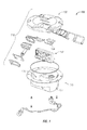
- FIG. 1 shows an exploded perspective view of a light fixture 100 in accordance with certain example embodiments.
- the light fixture 100 is an example of an airport runway and/or taxi way light fixture.
- the light fixture 100 of FIG. 1 includes a frame, a light source 104 , and a power supply 150 .
- the frame can include a cover 170 and optical housing 120 .
- the light fixture 100 further includes an optical housing assembly 110 .
- the optical housing assembly 110 includes the combination of one or more components associated with the mechanical structure and configuration of the optical housing 120 and other optical components, such as a body, lens, diffuser, connectors, and the like.
- the cover 170 includes at least one wall 177 that forms a cavity 174 . Inside of the cavity 174 can be positioned at least one or more light sources 104 and the power supply 150 .
- the cover 170 can include one or more features (e.g., ledges, apertures) that allow the various components disposed in the cavity 174 to fit and maintain electrical, mechanical, and/or thermal coupling with each other.
- the optical housing 120 protects the components disposed within the cavity 174 , and can also secure the light sources 104 and the other internal components 130 .
- the power supply 150 includes one or more circuits and electrical components configured to receive the constant current input from the central power source, condition the received current, and drive the light sources 104 .
- the power supply includes the power factor correction circuit disclosed herein, such that the input voltage is conditioned for power factor correction before it is supplied to the light sources 104 , thereby improving energy efficiency.
- the input current is an arbitrary periodic waveform rather than a pure sinusoid.
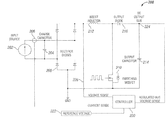
- FIG. 2 illustrates a schematic diagram of an example power factor correction (PFC) circuit 200 , in accordance with an example embodiment of the present disclosure.
- PFC power factor correction
- the PFC circuit 200 includes an input source 202 , an input charging capacitor 204 , a diode rectifier bridge 208 , an inductor 212 , a controller 220 , a switching device 210 , an output diode 216 , an output capacitor 214 , and a DC output bus 224 .
- the input source 202 provides a constant current power supply to the circuit 200 .
- the input source 202 is an arbitrary waveform.
- the input source 202 is directly coupled to the diode rectifier bridge 208 and the input charging capacitor 204 .
- the input current from the constant current input source 202 also charges the input charging capacitor 204 when the switching device 210 is off.
- the switch device 210 is a switching MOSFET.
- the switching device 210 is initially off. Thus, the input current from the constant current input source 202 charges the input charging capacitor 104 . As the input current charges the input charging capacitor 204 , a voltage rise occurs in the input charging capacitor 204 . When the voltage rises to a certain threshold level, the switching device 210 is switched on. In certain example embodiments, the threshold level is determined by a reference voltage 222 such that the voltage at the input charging capacitor is allowed to rise until it reaches the level of the reference voltage 222 . In certain example embodiments, the controller 220 provides the reference voltage 222 and also monitors a sensed voltage signal 226 of the voltage at the input charging capacitor 204 . The controller 220 also receives a sensed current signal 206 from the input current. The reference voltage has an amplitude indicative of the desired output power level. The controller 220 will be described in further detail below with respect to FIG. 3 .
- the switching device 210 When the voltage at the input charging capacitor 204 reaches the reference voltage 222 , the switching device 210 is switched on. When the switching device 210 is switched on, current is drained from the input charging capacitor 204 and the voltage drops accordingly. Thus, voltage at the input charging capacitor 204 rises when the switching device 210 is off and drops when the switching device 210 is on, creating a waveform which follows the duty cycle of the switching device 210 . During the time the switching device 210 is on, current rises in the inductor 212 . Thus, when the switching device 210 is switched off again, the inductor flies back and delivers energy, which is rectified by the output diode 216 , to the output capacitor 214 .
- the voltage at the output capacitor 214 is provided to a DC output bus 224 and configured to be delivered to a load.
- the switching device 210 switches at a high frequency (hundreds of kHz) according to a controlled duty cycle, the instantaneous voltage at the input charge capacitor 204 will match the reference voltage each cycle.
- an input voltage in which the waveform is matched to the waveform of the input current is created over time, despite the input current being an arbitrary waveform.
- the controller 220 does not necessarily monitor the input voltage 226 . Rather, the switching device is provided with a pulse width modulation signal shaped like a sine wave regardless of the input voltage, which forces the input voltage to take on a waveform as defined by the pulse width modulation signal.
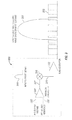
- FIG. 3 illustrates a diagrammatical representation of the controller 220 of FIG. 2 , in accordance with an example embodiment.
- the controller 220 includes a feedback controller 302 which receives, as inputs, a sense output voltage 303 from the DC output bus 224 and the reference voltage 222 .
- the controller 220 is a digital controller 220 having an analog to digital converter, which senses and samples digital values of the output voltage and input current.
- the value of the reference voltage 222 is typically selected according to the desired amount of power to be provided at the DC output bus 224 .
- the value of the sensed output voltage 303 is compared with the value of reference voltage 222 .
- the controller 220 illustrated in FIG. 3 and described above is provided as an example controller in the context of a constant-current PFC circuit. However, in certain other example embodiments of the present disclosure, the controller operates in a constant voltage PFC circuit in which the controller controls the constant voltage PFC circuit to shape the input current to be synchronized with the input voltage, thereby providing voltage-based power factor correction.
- the reference table 308 is derived from the input waveform 206 .
- the reference table 308 is derived from sampling the input waveform 308 through a “table record method”.
- the controller 220 initially acts as a standard controller to regulate the output voltage, providing a fixed duty cycle. During this time, the analog to digital converter in the controller 220 senses and stores digital values of the input current at fixed intervals.
- the input source is a constant voltage source
- the controller 220 initially regulates the input current with a fixed duty cycle. The controller 220 then senses and stores digital values of the input voltage at fixed intervals.
- the data is processed to create the reference table 308 .
- the sampled values are normalized by dividing each sampled value by the smallest value in the cycle, or cycle minimum, thereby generating the reference table 308 .
- the reference table 308 is multiplied by the feedback controller output 304 to generate a control signal 310 , which provides a duty cycle for controlling switching of the switching device 210 .
- the control signal 310 also varies in amplitude with the feedback controller output 304 .
- the reference table 308 is synchronized with the input source 206 either by peak or zero-crossing detection.
- the reference table 308 is updated periodically to account for changes in the shape or frequency of the input source 206 . Because the reference table 308 matches the arbitrary shape and frequency of the input source 206 waveform, a high power factor can be achieved.
- the input source 206 is a constant current input. In certain other example embodiments, the input source 206 is a constant voltage input.
- the reference table 308 is derived from the input source 206 through an “instantaneous normalized method”.
- the controller 220 instead of sampling a series of values of the input source 206 (i.e., input current for constant current, input voltage for constant voltage), the controller 220 stores only the maximum input source value for each cycle. Then, at a given intervals, such as at fixed intervals where control algorithms are processed, the instantaneous value of the input source 206 is divided by the cycle maximum. The result of which is immediately multiplied by the feedback controller output 304 to produce an appropriate duty cycle for power factor correction.
- the controller 220 further includes a pulse width modulation (PWM) generator 312 .
- the PWM generator 312 receives as input, the control signal 310 , and converts the control signal 310 into a pulse width modulation signal 316 .
- the pulse width modulation signal 316 is used to drive the switching device 210 ( FIG. 2 ).
- the duty cycle of the pulse width modulation signal 316 decreases to increase the input voltage 226
- the pulse modulation signal 316 increases to decrease the input voltage 226 .
- the input voltage waveform is matched to that of the input current 206 .
- the input current would be made to match the waveform of the input voltage.
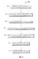
- FIG. 4 illustrates the table record method 400 of power factor correction for an arbitrary input waveform, in accordance with an example embodiment.
- the method 400 is embodied in an algorithm to be carried out by the controller 220 ( FIG. 3 ) of the PFC circuit 200 .
- the following description of the table record method 400 is described in the context of an example embodiment in which the input is a constant current source, and a matching input voltage waveform is to be generated.
- the table record method 400 is also used to generate an input current waveform synchronized with a constant voltage input.
- the method 400 includes regulating the output voltage of the PFC circuit 200 with an initial fixed duty cycle (step 402 ).
- the controller 220 then samples the input current at fixed intervals for a full cycle and stores the sampled values (step 404 ).
- the controller divides each stored value by the cycle minimum, of lowest stored value per cycle (step 406 ).
- the method 400 further includes populating the reference table 308 or an array with the results of step 406 (step 408 ).
- the reference table 308 is synchronized with the input current 206 either by peak or zero-current detection. In certain embodiments, the reference table 308 is also updated periodically to account for changes in the shape or frequency of the input current.
- the method also includes multiplying 306 the reference table 308 with the feedback controller output 304 , which includes instructions for maintaining a desired amplitude of the input voltage (step 410 ).
- the output of the multiplication is the control signal 310 .
- the method 400 further includes converting the control signal 310 into a corresponding pulse width modulation signal 316 (step 412 ).
- the pulse width modulation signal 316 is then used to control the switching device 210 ( FIG. 2 ) such that the input voltage 226 is synchronized with the input current 206 (step 414 ).
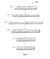
- FIG. 5 illustrates the instantaneous normalized method 500 of power factor correction for an arbitrary input waveform.
- the instantaneous normalized method 500 can also be used to generate an input current waveform synchronized with a constant voltage input.
- the instantaneous normalized method 500 includes regulating the output voltage of the PFC circuit 200 with an initial fixed duty cycle (step 502 ).
- the controller 220 senses the input current and records the normalized cycle maximum, or largest value in a cycle (step 504 ). Then, at determined intervals, the instantaneous value of the input current is divided by the normalized cycle maximum (step 506 ).
- step 506 is immediately multiplied by the feedback controller output 304 to generate a control signal 310 (step 508 ).
- the control signal 310 is converted into a pulse width modulation signal 316 (step 510 ).
- the pulse width modulation signal is then used to control the switching device 210 in order to generate an input voltage 226 that is synchronized with the input current 206 (step 512 ).
- the input voltage of a constant current power correction circuit is made to match and follow the phase of the constant current input current. Thus, power efficiency is improved.
Abstract
Description
- The present disclosure relates generally to power factor correction. Specifically, the present disclosure relates to techniques for providing power factor correction for an arbitrary, periodic waveform source.
- Power factor correction is often used in electric power systems and between power sources and loads in order to synchronize the input current and the input voltage before it is delivered to the load. Power factor correction can provide many benefits to the electric power system and the load, such as prolonged life and energy efficiency.
- Traditionally, power factor correction circuitry is designed as voltage-based power factor correction. Such circuitry is used in constant voltage systems, and the input current waveform is made to match the input voltage waveform. Additionally, standard digital power factor correction methods utilize a 60 hertz sine wave as a reference to match the waveform of the input current to the input voltage. However, in certain industries, such as airfield lighting, the existing infrastructure requires current based systems which require a constant current power source rather than a constant voltage power source. Specifically, in the area of airfield lighting, constant current systems are traditionally used because of the need for consistent brightness across the plurality of light fixtures coupled in series and being powered by the same power source. Because a constant current power supply can provide the same level of current to each of the light fixtures, it became the standard form of power distribution in the area of airfield lighting. Though lighting technology has become more sophisticated, the infrastructure has remained a current based system. However, power factor correction techniques used for voltage based systems which receive a constant voltage generally cannot be used for current based systems. Furthermore, in airfield lighting systems and other constant current or constant voltage systems, many power sources do not supply a true sine wave input. For example, series-switch regulators used in airfield lighting are non-sinusoidal power sources. Other examples include emergency generators which may produce a sine wave, but at a varying frequency, and certain power inverters may produce square waveforms. However, traditional sine-based power factor correction requires the input waveform to be substantially similar to a sine wave for good power factor correction. The same challenge exists for power factor correction of constant-voltage systems when the input voltage is not a regular sinusoidal waveform. Thus, power factor correction of non-sinusoidal constant voltage or constant current inputs using the traditional sine-based method is limited or less efficient.
- In an example embodiment of the present disclosure, a power factor correction (PFC) circuit for arbitrary input waveforms includes a controller configured to receive an output signal from a PFC circuit and a reference signal. The controller compares the output signal and the reference signal and produces a feedback output, wherein the controller generates input reference data derived from an input source and multiplies the input reference data by the feedback output to produce a control signal. The input source is an arbitrary periodic waveform and the control signal controls and synchronizes an input signal to be in phase with the input source.
- In another example embodiment of the present disclosure, a table method of controlling a power factor correction (PFC) circuit with arbitrary input waveforms includes sampling an input source at fixed intervals and storing the sampled values, dividing each sampled value by a cycle minimum to obtain a set of normalized values, and generating an input reference from the set of normalized values. The input reference is multiplied by a feedback controller output to obtain a control signal. The PFC circuit is controlled with the control signal, wherein the PFC circuit produces an input signal synchronized with the input source.
- In another example embodiment of the present disclosure, an instantaneous method of controlling a power factor correction (PFC) circuit with arbitrary input waveforms includes sensing a first input power parameter, taking an instantaneous value of the first input power parameter at fixed intervals, and multiplying the instantaneous value of the first input power parameter by a feedback controller output to generate a control signal. The PFC circuit is controlled with the control signal, wherein a second input power parameter is synchronized with the first input power parameter.
- For a more complete understanding of the disclosure and the advantages thereof, reference is now made to the following description, in conjunction with the accompanying figures briefly described as follows:
-
FIG. 1 illustrates a light fixture having a power factor correction circuit for arbitrary waveforms, in accordance with an example embodiment of the present disclosure; -
FIG. 2 illustrates a schematic diagram of a power factor correction circuit for arbitrary waveforms, in accordance with an example embodiment of the present disclosure; -
FIG. 3 illustrates a diagram of a controller of the power factor correction circuit for arbitrary waveforms ofFIG. 1 , in accordance with an example embodiment of the present disclosure; -
FIG. 4 illustrates, a flow chart of a table record method of power factor correction for arbitrary waveforms, in accordance with an example embodiment of the present disclosure; and -
FIG. 5 illustrates a flow chart of an instantaneous normalized method of power factor correction for arbitrary waveforms, in accordance with an example embodiment of the present disclosure. - The drawings illustrate only example embodiments of the disclosure and are therefore not to be considered limiting of its scope, as the disclosure may admit to other equally effective embodiments. The elements and features shown in the drawings are not necessarily to scale, emphasis instead being placed upon clearly illustrating the principles of example embodiments of the present disclosure. Additionally, certain dimensions may be exaggerated to help visually convey such principles.
- In the following paragraphs, the present disclosure will be described in further detail by way of examples with reference to the attached drawings. In the description, well known components, methods, and/or processing techniques are omitted or briefly described so as not to obscure the disclosure. As used herein, the “present disclosure” refers to any one of the embodiments of the disclosure described herein and any equivalents. Furthermore, reference to various feature(s) of the “present disclosure” is not to suggest that ail embodiments must include the referenced feature(s). The present disclosure provides systems and methods of power factor correction for a power converter receiving an input having an arbitrary periodic waveform, operating on a constant current input source. The present disclosure describes a constant current power distribution system in the area of airfield lighting as an example application, but may be used with any other appropriate power distribution systems and loads operating on constant current or constant voltage input sources.
- In certain example embodiments, the present disclosure provides a power factor correction circuit for systems receiving inputs having arbitrary waveforms. Arbitrary input waveforms as referenced herein refer either to non-sinusoidal waveforms or sinusoidal waveforms with irregular frequencies. The present disclosure provides a power factor correction circuit which applies an arbitrary waveform power factor correction algorithm to perform power factor correction of the arbitrary input waveform. The following discloses two example embodiments of the arbitrary waveform power factor correction algorithm and an example power factor correction circuit to be used With the algorithms for carrying out arbitrary waveform power factor correction. The disclosed power factor correction algorithms allow for high power factor correction on arbitrary waveform sources. In one example, the power factor correction circuit is used in an airfield lighting system which includes a plurality of individual light fixtures. Each of the light fixtures receives a constant current power supply from a central power source. In certain example embodiments, each or a subset of the light fixtures includes the power factor correction circuit disclosed herein, which improves the energy efficiency of the light fixtures.
-
FIG. 1 shows an exploded perspective view of alight fixture 100 in accordance with certain example embodiments. Referring now toFIG. 1 , thelight fixture 100 is an example of an airport runway and/or taxi way light fixture. Thelight fixture 100 ofFIG. 1 includes a frame, alight source 104, and apower supply 150. The frame can include acover 170 andoptical housing 120. Thelight fixture 100 further includes anoptical housing assembly 110. Theoptical housing assembly 110 includes the combination of one or more components associated with the mechanical structure and configuration of theoptical housing 120 and other optical components, such as a body, lens, diffuser, connectors, and the like. - In certain example embodiments, the
cover 170 includes at least onewall 177 that forms acavity 174. Inside of thecavity 174 can be positioned at least one or morelight sources 104 and thepower supply 150. Thecover 170 can include one or more features (e.g., ledges, apertures) that allow the various components disposed in thecavity 174 to fit and maintain electrical, mechanical, and/or thermal coupling with each other. Theoptical housing 120 protects the components disposed within thecavity 174, and can also secure thelight sources 104 and the other internal components 130. - The
power supply 150 includes one or more circuits and electrical components configured to receive the constant current input from the central power source, condition the received current, and drive thelight sources 104. In certain example embodiments, the power supply includes the power factor correction circuit disclosed herein, such that the input voltage is conditioned for power factor correction before it is supplied to thelight sources 104, thereby improving energy efficiency. In certain example embodiments, the input current is an arbitrary periodic waveform rather than a pure sinusoid. -
FIG. 2 illustrates a schematic diagram of an example power factor correction (PFC)circuit 200, in accordance with an example embodiment of the present disclosure. It should be noted that thePFC circuit 200 ofFIG. 2 is provided as an example only, and the techniques and methods provided in this disclosure can be implemented using many other PFC hardware and circuit configurations, including both constant current PFC circuits and constant voltage PFC circuits. - Referring to
FIG. 2 , in certain example embodiments, thePFC circuit 200 includes aninput source 202, aninput charging capacitor 204, adiode rectifier bridge 208, aninductor 212, acontroller 220, aswitching device 210, anoutput diode 216, anoutput capacitor 214, and aDC output bus 224. In an example embodiment, theinput source 202 provides a constant current power supply to thecircuit 200. In certain example embodiments, theinput source 202 is an arbitrary waveform. In certain example embodiments, theinput source 202 is directly coupled to thediode rectifier bridge 208 and theinput charging capacitor 204. Thus, the input current is rectified by thediode rectifier bridge 208. The input current from the constantcurrent input source 202 also charges theinput charging capacitor 204 when theswitching device 210 is off. In certain example embodiments, theswitch device 210 is a switching MOSFET. - In certain example embodiments, the
switching device 210 is initially off. Thus, the input current from the constantcurrent input source 202 charges theinput charging capacitor 104. As the input current charges theinput charging capacitor 204, a voltage rise occurs in theinput charging capacitor 204. When the voltage rises to a certain threshold level, theswitching device 210 is switched on. In certain example embodiments, the threshold level is determined by areference voltage 222 such that the voltage at the input charging capacitor is allowed to rise until it reaches the level of thereference voltage 222. In certain example embodiments, thecontroller 220 provides thereference voltage 222 and also monitors a sensedvoltage signal 226 of the voltage at theinput charging capacitor 204. Thecontroller 220 also receives a sensedcurrent signal 206 from the input current. The reference voltage has an amplitude indicative of the desired output power level. Thecontroller 220 will be described in further detail below with respect toFIG. 3 . - When the voltage at the
input charging capacitor 204 reaches thereference voltage 222, theswitching device 210 is switched on. When theswitching device 210 is switched on, current is drained from theinput charging capacitor 204 and the voltage drops accordingly. Thus, voltage at theinput charging capacitor 204 rises when theswitching device 210 is off and drops when theswitching device 210 is on, creating a waveform which follows the duty cycle of theswitching device 210. During the time theswitching device 210 is on, current rises in theinductor 212. Thus, when theswitching device 210 is switched off again, the inductor flies back and delivers energy, which is rectified by theoutput diode 216, to theoutput capacitor 214. The voltage at theoutput capacitor 214 is provided to aDC output bus 224 and configured to be delivered to a load. As theswitching device 210 switches at a high frequency (hundreds of kHz) according to a controlled duty cycle, the instantaneous voltage at theinput charge capacitor 204 will match the reference voltage each cycle. Thus, an input voltage in which the waveform is matched to the waveform of the input current is created over time, despite the input current being an arbitrary waveform. - In another example embodiment, the
controller 220 does not necessarily monitor theinput voltage 226. Rather, the switching device is provided with a pulse width modulation signal shaped like a sine wave regardless of the input voltage, which forces the input voltage to take on a waveform as defined by the pulse width modulation signal. -
FIG. 3 illustrates a diagrammatical representation of thecontroller 220 ofFIG. 2 , in accordance with an example embodiment. Thecontroller 220 includes afeedback controller 302 which receives, as inputs, asense output voltage 303 from theDC output bus 224 and thereference voltage 222. In certain example embodiments, thecontroller 220 is adigital controller 220 having an analog to digital converter, which senses and samples digital values of the output voltage and input current. The value of thereference voltage 222 is typically selected according to the desired amount of power to be provided at theDC output bus 224. The value of the sensedoutput voltage 303 is compared with the value ofreference voltage 222. If the value of the sensedoutput voltage 303 is below the value of thereference voltage 222, theoutput 304 of thefeedback controller 302 will increase. If the value of the sensedoutput voltage 303 is above the value of thereference voltage 222, theoutput 304 of thefeedback controller 302 will decrease. Theoutput 304 of thefeedback controller 302 is then multiplied 306 by an input waveform reference table 308 to generate acontrol signal 310 which includes input waveform data and desired amplitude data. Thecontroller 220 illustrated inFIG. 3 and described above is provided as an example controller in the context of a constant-current PFC circuit. However, in certain other example embodiments of the present disclosure, the controller operates in a constant voltage PFC circuit in which the controller controls the constant voltage PFC circuit to shape the input current to be synchronized with the input voltage, thereby providing voltage-based power factor correction. - In certain example embodiments, the reference table 308 is derived from the
input waveform 206. Specifically, in an example embodiment, the reference table 308 is derived from sampling theinput waveform 308 through a “table record method”. In the table record method, thecontroller 220 initially acts as a standard controller to regulate the output voltage, providing a fixed duty cycle. During this time, the analog to digital converter in thecontroller 220 senses and stores digital values of the input current at fixed intervals. In certain example embodiments, in which the input source is a constant voltage source, thecontroller 220 initially regulates the input current with a fixed duty cycle. Thecontroller 220 then senses and stores digital values of the input voltage at fixed intervals. Once a full cycle of input readings has been taken, the data is processed to create the reference table 308. Specifically, the sampled values are normalized by dividing each sampled value by the smallest value in the cycle, or cycle minimum, thereby generating the reference table 308. The reference table 308 is multiplied by thefeedback controller output 304 to generate acontrol signal 310, which provides a duty cycle for controlling switching of theswitching device 210. Thecontrol signal 310 also varies in amplitude with thefeedback controller output 304. In certain example embodiments, the reference table 308 is synchronized with theinput source 206 either by peak or zero-crossing detection. Additionally, in certain example embodiments, the reference table 308 is updated periodically to account for changes in the shape or frequency of theinput source 206. Because the reference table 308 matches the arbitrary shape and frequency of theinput source 206 waveform, a high power factor can be achieved. In certain example embodiments, theinput source 206 is a constant current input. In certain other example embodiments, theinput source 206 is a constant voltage input. - In another example embodiment, the reference table 308 is derived from the
input source 206 through an “instantaneous normalized method”. In the instantaneous normalized method, instead of sampling a series of values of the input source 206 (i.e., input current for constant current, input voltage for constant voltage), thecontroller 220 stores only the maximum input source value for each cycle. Then, at a given intervals, such as at fixed intervals where control algorithms are processed, the instantaneous value of theinput source 206 is divided by the cycle maximum. The result of which is immediately multiplied by thefeedback controller output 304 to produce an appropriate duty cycle for power factor correction. - In certain example embodiments, the
controller 220 further includes a pulse width modulation (PWM)generator 312. ThePWM generator 312 receives as input, thecontrol signal 310, and converts thecontrol signal 310 into a pulsewidth modulation signal 316. The pulsewidth modulation signal 316 is used to drive the switching device 210 (FIG. 2 ). In certain example embodiments, as in the example constant-current PFC circuit 200, the duty cycle of the pulsewidth modulation signal 316 decreases to increase theinput voltage 226, and thepulse modulation signal 316 increases to decrease theinput voltage 226. By using thePWM signal 316, which is derived from thecontrol signal 310, to control switching of theswitching device 210, the input voltage waveform is matched to that of the input current 206. For example, in a constant voltage system, the input current would be made to match the waveform of the input voltage. -
FIG. 4 illustrates thetable record method 400 of power factor correction for an arbitrary input waveform, in accordance with an example embodiment. In certain example embodiments, themethod 400 is embodied in an algorithm to be carried out by the controller 220 (FIG. 3 ) of thePFC circuit 200. The following description of thetable record method 400 is described in the context of an example embodiment in which the input is a constant current source, and a matching input voltage waveform is to be generated. However, in other example embodiments, thetable record method 400 is also used to generate an input current waveform synchronized with a constant voltage input. Referring toFIGS. 3 and 4 , in an example embodiment, themethod 400 includes regulating the output voltage of thePFC circuit 200 with an initial fixed duty cycle (step 402). Thecontroller 220 then samples the input current at fixed intervals for a full cycle and stores the sampled values (step 404). The controller divides each stored value by the cycle minimum, of lowest stored value per cycle (step 406). Themethod 400 further includes populating the reference table 308 or an array with the results of step 406 (step 408). The reference table 308 is synchronized with the input current 206 either by peak or zero-current detection. In certain embodiments, the reference table 308 is also updated periodically to account for changes in the shape or frequency of the input current. The method also includes multiplying 306 the reference table 308 with thefeedback controller output 304, which includes instructions for maintaining a desired amplitude of the input voltage (step 410). The output of the multiplication is thecontrol signal 310. Themethod 400 further includes converting thecontrol signal 310 into a corresponding pulse width modulation signal 316 (step 412). The pulsewidth modulation signal 316 is then used to control the switching device 210 (FIG. 2 ) such that theinput voltage 226 is synchronized with the input current 206 (step 414). -
FIG. 5 illustrates the instantaneous normalizedmethod 500 of power factor correction for an arbitrary input waveform. Again, the following example embodiment is based on a constant current system. However, in other example embodiments, the instantaneous normalizedmethod 500 can also be used to generate an input current waveform synchronized with a constant voltage input. Like thetable record method 400, the instantaneous normalizedmethod 500 includes regulating the output voltage of thePFC circuit 200 with an initial fixed duty cycle (step 502). Thecontroller 220 then senses the input current and records the normalized cycle maximum, or largest value in a cycle (step 504). Then, at determined intervals, the instantaneous value of the input current is divided by the normalized cycle maximum (step 506). The result ofstep 506 is immediately multiplied by thefeedback controller output 304 to generate a control signal 310 (step 508). In certain example embodiments, thecontrol signal 310 is converted into a pulse width modulation signal 316 (step 510). The pulse width modulation signal is then used to control theswitching device 210 in order to generate aninput voltage 226 that is synchronized with the input current 206 (step 512). With thetable record method 400 and the instantaneous normalizedmethod 500, the input voltage of a constant current power correction circuit is made to match and follow the phase of the constant current input current. Thus, power efficiency is improved. - The present disclosure provides techniques for power factor correction of arbitrary input sources. Although embodiments of the present disclosure have been described herein in detail, the descriptions are by way of example. The features of the disclosure described herein are representative and, in alternative embodiments, certain features and elements may be added or omitted. Additionally, modifications to aspects of the embodiments described herein may be made by those skilled in the art without departing from the spirit and scope of the present disclosure defined in the following claims, the scope of which are to be accorded the broadest interpretation so as to encompass modifications and equivalent structures.
Claims (20)
Priority Applications (4)
| Application Number | Priority Date | Filing Date | Title |
|---|---|---|---|
| US13/887,210 US9000736B2 (en) | 2013-05-03 | 2013-05-03 | Power factor correction algorithm for arbitrary input waveform |
| EP14791846.0A EP2992469B1 (en) | 2013-05-03 | 2014-04-30 | Power factor correction algorithm for arbitrary input waveform |
| PCT/US2014/036256 WO2014179503A1 (en) | 2013-05-03 | 2014-04-30 | Power factor correction algorithm for arbitrary input waveform |
| BR112015027694-6A BR112015027694B1 (en) | 2013-05-03 | 2014-04-30 | POWER FACTOR CORRECTION CIRCUIT, TAB METHOD FOR CONTROLLING A POWER FACTOR CORRECTION CIRCUIT AND INSTANT METHOD FOR CONTROLLING A POWER FACTOR CORRECTION CIRCUIT |
Applications Claiming Priority (1)
| Application Number | Priority Date | Filing Date | Title |
|---|---|---|---|
| US13/887,210 US9000736B2 (en) | 2013-05-03 | 2013-05-03 | Power factor correction algorithm for arbitrary input waveform |
Publications (2)
| Publication Number | Publication Date |
|---|---|
| US20140327411A1 true US20140327411A1 (en) | 2014-11-06 |
| US9000736B2 US9000736B2 (en) | 2015-04-07 |
Family
ID=51841120
Family Applications (1)
| Application Number | Title | Priority Date | Filing Date |
|---|---|---|---|
| US13/887,210 Active 2033-10-09 US9000736B2 (en) | 2013-05-03 | 2013-05-03 | Power factor correction algorithm for arbitrary input waveform |
Country Status (4)
| Country | Link |
|---|---|
| US (1) | US9000736B2 (en) |
| EP (1) | EP2992469B1 (en) |
| BR (1) | BR112015027694B1 (en) |
| WO (1) | WO2014179503A1 (en) |
Cited By (9)
| Publication number | Priority date | Publication date | Assignee | Title |
|---|---|---|---|---|
| US20140328096A1 (en) * | 2013-05-03 | 2014-11-06 | Traver Gumaer | Active power factor correction circuit for a constant current power converter |
| US9190901B2 (en) | 2013-05-03 | 2015-11-17 | Cooper Technologies Company | Bridgeless boost power factor correction circuit for constant current input |
| US20160079868A1 (en) * | 2014-09-11 | 2016-03-17 | Acbel Polytech Inc. | Power supply and method for compensating low-frequency output voltage ripple thereof |
| US9548794B2 (en) | 2013-05-03 | 2017-01-17 | Cooper Technologies Company | Power factor correction for constant current input with power line communication |
| US20170059139A1 (en) | 2015-08-26 | 2017-03-02 | Abl Ip Holding Llc | Led luminaire |
| US20180041120A1 (en) * | 2016-08-03 | 2018-02-08 | Schneider Electric It Corporation | High step down dc/dc converter |
| US20180254713A1 (en) * | 2015-09-18 | 2018-09-06 | The Esab Group Inc. | Printed circuit board arrangement for welding and cutting apparatus |
| US10251279B1 (en) | 2018-01-04 | 2019-04-02 | Abl Ip Holding Llc | Printed circuit board mounting with tabs |
| CN110291818A (en) * | 2016-12-15 | 2019-09-27 | 株式会社Ntt都科摩 | User terminal and wireless communications method |
Citations (14)
| Publication number | Priority date | Publication date | Assignee | Title |
|---|---|---|---|---|
| US5844399A (en) * | 1996-07-26 | 1998-12-01 | The University Of Toledo | Battery charger control system |
| US6177782B1 (en) * | 1997-12-09 | 2001-01-23 | Semiconductor Components Industries, Llc | Circuit and method of controlling a regulator with an output feedback signal and devoid of an input feedforward signal |
| US6657417B1 (en) * | 2002-05-31 | 2003-12-02 | Champion Microelectronic Corp. | Power factor correction with carrier control and input voltage sensing |
| US20070036212A1 (en) * | 2005-05-06 | 2007-02-15 | Silicon Laboratories Inc. | Digital Controller Based Power Factor Correction Circuit |
| US7394236B2 (en) * | 2005-03-18 | 2008-07-01 | Power-One, Inc. | Digital double-loop output voltage regulation |
| US7554310B2 (en) * | 2005-03-18 | 2009-06-30 | Power-One, Inc. | Digital double-loop output voltage regulation |
| US7723964B2 (en) * | 2004-12-15 | 2010-05-25 | Fujitsu General Limited | Power supply device |
| US7821237B2 (en) * | 2007-05-02 | 2010-10-26 | Cirrus Logic, Inc. | Power factor correction (PFC) controller and method using a finite state machine to adjust the duty cycle of a PWM control signal |
| US20110193494A1 (en) * | 2010-02-09 | 2011-08-11 | Power Integrations, Inc. | Integrated on-time extension for non-dissipative bleeding in a power supply |
| US8587970B2 (en) * | 2010-03-09 | 2013-11-19 | Murata Manufacturing Co., Ltd. | Isolated switching power supply apparatus including primary-side and secondary-side digital control circuits |
| US20130322139A1 (en) * | 2012-06-01 | 2013-12-05 | The University Of Hong Kong | Input ac voltage control bi-directional power converters |
| US20140078798A1 (en) * | 2010-12-24 | 2014-03-20 | Semiconductor Components Industries, Llc | Power factor controller and method |
| US20140328097A1 (en) * | 2013-05-03 | 2014-11-06 | Traver Gumaer | Bridgeless boost power factor correction circuit for constant current input |
| US20140328096A1 (en) * | 2013-05-03 | 2014-11-06 | Traver Gumaer | Active power factor correction circuit for a constant current power converter |
Family Cites Families (61)
| Publication number | Priority date | Publication date | Assignee | Title |
|---|---|---|---|---|
| US4386395A (en) | 1980-12-19 | 1983-05-31 | Webster Electric Company, Inc. | Power supply for electrostatic apparatus |
| US4683529A (en) | 1986-11-12 | 1987-07-28 | Zytec Corporation | Switching power supply with automatic power factor correction |
| US5019952A (en) | 1989-11-20 | 1991-05-28 | General Electric Company | AC to DC power conversion circuit with low harmonic distortion |
| US5367247A (en) | 1992-08-10 | 1994-11-22 | International Business Machines Corporation | Critically continuous boost converter |
| US5442539A (en) * | 1992-10-02 | 1995-08-15 | California Institute Of Technology | CuK DC-to-DC switching converter with input current shaping for unity power factor operation |
| KR100342457B1 (en) | 1994-02-10 | 2002-11-02 | 코닌클리케 필립스 일렉트로닉스 엔.브이. | High frequency ac/ac converter with power factor correction |
| US5568041A (en) | 1995-02-09 | 1996-10-22 | Magnetek, Inc. | Low-cost power factor correction circuit and method for electronic ballasts |
| DK0732797T3 (en) | 1995-03-16 | 2002-03-18 | Franklin Electric Co Inc | Power factor correction |
| DE69506098T2 (en) | 1995-07-31 | 1999-04-15 | Hewlett Packard Co | Switched-mode switching power supply with power factor correction |
| US5631550A (en) | 1996-04-25 | 1997-05-20 | Lockheed Martin Tactical Defense Systems | Digital control for active power factor correction |
| US5804950A (en) | 1996-06-20 | 1998-09-08 | Micro Linear Corporation | Input current modulation for power factor correction |
| KR100280639B1 (en) | 1998-05-22 | 2001-02-01 | 김덕중 | Power factor correction circuit |
| US6043633A (en) | 1998-06-05 | 2000-03-28 | Systel Development & Industries | Power factor correction method and apparatus |
| KR100595537B1 (en) | 1999-07-20 | 2006-07-03 | 엘지전자 주식회사 | The power factor control apparatus and method |
| US7088079B2 (en) | 2000-09-05 | 2006-08-08 | Minebea Co. Ltd. | Active power factor correction |
| US6906503B2 (en) | 2002-01-25 | 2005-06-14 | Precor Incorporated | Power supply controller for exercise equipment drive motor |
| US6909622B2 (en) | 2002-11-05 | 2005-06-21 | Da Feng Weng | Quasi active power factor correction circuit for switching power supply |
| ITMI20031315A1 (en) | 2003-06-27 | 2004-12-28 | St Microelectronics Srl | DEVICE FOR CORRECTION OF THE POWER FACTOR IN FORCED SWITCHING POWER SUPPLIES. |
| US7391630B2 (en) | 2003-10-24 | 2008-06-24 | Pf1, Inc. | Method and system for power factor correction using constant pulse proportional current |
| US7279868B2 (en) | 2004-03-12 | 2007-10-09 | Comarco Wireless Technologies, Inc. | Power factor correction circuits |
| US7180273B2 (en) | 2004-06-07 | 2007-02-20 | International Rectifier Corporation | Low switching frequency power factor correction circuit |
| US7551464B2 (en) | 2004-09-29 | 2009-06-23 | Weibin Chen | Current overloading proof switch power supply and its IC |
| US7205749B2 (en) | 2005-02-28 | 2007-04-17 | Texas Instruments Incorporated | Power line communication using power factor correction circuits |
| US7598717B2 (en) * | 2005-04-08 | 2009-10-06 | Northrop Grumman Corporation | Current-sourced power supplies |
| US7269038B2 (en) | 2005-09-12 | 2007-09-11 | Fairchild Semiconductor Corporation | Vrms and rectified current sense full-bridge synchronous-rectification integrated with PFC |
| US7323851B2 (en) | 2005-09-22 | 2008-01-29 | Artesyn Technologies, Inc. | Digital power factor correction controller and AC-to-DC power supply including same |
| CN101426811A (en) | 2006-04-21 | 2009-05-06 | 特朗斯吉恩股份有限公司 | Hpv-16-based papillomavirus vaccine |
| WO2008018095A1 (en) | 2006-08-07 | 2008-02-14 | Stmicroelectronics S.R.L. | Fixed-off-time power factor correction controller |
| US7889517B2 (en) | 2006-12-01 | 2011-02-15 | Flextronics International Usa, Inc. | Power system with power converters having an adaptive controller |
| US9197132B2 (en) | 2006-12-01 | 2015-11-24 | Flextronics International Usa, Inc. | Power converter with an adaptive controller and method of operating the same |
| US8076920B1 (en) | 2007-03-12 | 2011-12-13 | Cirrus Logic, Inc. | Switching power converter and control system |
| US7683595B2 (en) | 2007-04-10 | 2010-03-23 | Infineon Technologies Austria Ag | Method for actuation, and actuating circuit for a switch in a power factor correction circuit |
| US7919958B2 (en) | 2007-05-18 | 2011-04-05 | Texas Instruments Incorporated | Methods and apparatus for controlling a digital power supply |
| US8130522B2 (en) | 2007-06-15 | 2012-03-06 | The Regents Of The University Of Colorado, A Body Corporate | Digital power factor correction |
| US8102167B2 (en) | 2008-03-25 | 2012-01-24 | Microsemi Corporation | Phase-cut dimming circuit |
| US7746040B2 (en) | 2008-04-11 | 2010-06-29 | Flextronics Ap, Llc | AC to DC converter with power factor correction |
| US20110109283A1 (en) | 2008-06-06 | 2011-05-12 | Infineon Technologies Austria Ag | System and method for controlling a converter |
| US8279628B2 (en) | 2008-07-25 | 2012-10-02 | Cirrus Logic, Inc. | Audible noise suppression in a resonant switching power converter |
| KR101497062B1 (en) | 2008-07-25 | 2015-03-05 | 페어차일드코리아반도체 주식회사 | Switch controller, switch control method, and converter using the same |
| KR20110069828A (en) * | 2008-09-26 | 2011-06-23 | 엑슬런트 에너지 테크놀로지스, 엘엘씨 | Adaptive generation and control of arbitrary electrical waveforms in a grid-tied power conversion system |
| US8279630B2 (en) | 2008-10-14 | 2012-10-02 | Fairchild Semiconductor Corporation | Continuous conduction mode power factor correction circuit with reduced sensing requirements |
| JP5080424B2 (en) | 2008-11-10 | 2012-11-21 | 富士通テレコムネットワークス株式会社 | Power supply |
| JP5277952B2 (en) | 2008-12-25 | 2013-08-28 | 富士電機株式会社 | Switching power supply circuit |
| US8129958B2 (en) | 2009-03-25 | 2012-03-06 | Evergreen Micro Devices Co., Ltd. | Transition mode power factor correction device with built-in automatic total harmonic distortion reduction feature |
| US8094472B2 (en) | 2009-06-02 | 2012-01-10 | Rhymebus Corporation | Power factor correction converter capable of fast adjusting load |
| US8379421B2 (en) | 2009-06-10 | 2013-02-19 | Oita University | Power factor correction converter with parallel-connected converter sections |
| US8228046B2 (en) | 2009-06-16 | 2012-07-24 | American Power Conversion Corporation | Apparatus and method for operating an uninterruptible power supply |
| US8248145B2 (en) | 2009-06-30 | 2012-08-21 | Cirrus Logic, Inc. | Cascode configured switching using at least one low breakdown voltage internal, integrated circuit switch to control at least one high breakdown voltage external switch |
| TW201119504A (en) | 2009-08-18 | 2011-06-01 | Koninkl Philips Electronics Nv | Method and apparatus providing universal voltage input for solid state light fixtures |
| US20120106216A1 (en) | 2010-04-29 | 2012-05-03 | Victor Tzinker | Ac-dc converter with unity power factor |
| EP2387137B1 (en) | 2010-05-13 | 2013-07-17 | Nxp B.V. | An SMPS having a saftey arrangement, a method of operating a SMPS, and a controller therefor |
| GB201011081D0 (en) | 2010-07-01 | 2010-08-18 | Macfarlane Alistair | Improved semi resonant switching regulator, power factor control and LED lighting |
| US8829865B2 (en) | 2010-07-13 | 2014-09-09 | General Electric Company | Power factor correction efficiency improvement circuit, a converter employing the circuit and a method of manufacturing a converter |
| GB201012469D0 (en) * | 2010-07-26 | 2010-09-08 | Texas Instr Cork Ltd | Line current waveshaping |
| JP2012070490A (en) | 2010-09-21 | 2012-04-05 | Tdk Corp | Bridgeless power factor improvement converter |
| US8541990B2 (en) | 2010-11-23 | 2013-09-24 | Immense Advance Technology Corp. | Power conversion controller having a novel power factor correction mechanism using line voltage normalization |
| KR20120078947A (en) | 2011-01-03 | 2012-07-11 | 페어차일드코리아반도체 주식회사 | Switch control circuit, converter using the same, and switch controlling method |
| JP5289471B2 (en) | 2011-01-21 | 2013-09-11 | 三菱電機株式会社 | Light source lighting device and lighting device |
| CN102710118B (en) | 2012-06-28 | 2014-10-29 | 成都芯源系统有限公司 | Power factor correction circuit as well as control circuit and method thereof |
| US8937469B2 (en) | 2012-10-09 | 2015-01-20 | Delta-Q Technologies Corp. | Digital controller based detection methods for adaptive mixed conduction mode power factor correction circuit |
| US9548794B2 (en) | 2013-05-03 | 2017-01-17 | Cooper Technologies Company | Power factor correction for constant current input with power line communication |
-
2013
- 2013-05-03 US US13/887,210 patent/US9000736B2/en active Active
-
2014
- 2014-04-30 WO PCT/US2014/036256 patent/WO2014179503A1/en active Application Filing
- 2014-04-30 BR BR112015027694-6A patent/BR112015027694B1/en active IP Right Grant
- 2014-04-30 EP EP14791846.0A patent/EP2992469B1/en active Active
Patent Citations (15)
| Publication number | Priority date | Publication date | Assignee | Title |
|---|---|---|---|---|
| US5844399A (en) * | 1996-07-26 | 1998-12-01 | The University Of Toledo | Battery charger control system |
| US6177782B1 (en) * | 1997-12-09 | 2001-01-23 | Semiconductor Components Industries, Llc | Circuit and method of controlling a regulator with an output feedback signal and devoid of an input feedforward signal |
| US6657417B1 (en) * | 2002-05-31 | 2003-12-02 | Champion Microelectronic Corp. | Power factor correction with carrier control and input voltage sensing |
| US7723964B2 (en) * | 2004-12-15 | 2010-05-25 | Fujitsu General Limited | Power supply device |
| US7394236B2 (en) * | 2005-03-18 | 2008-07-01 | Power-One, Inc. | Digital double-loop output voltage regulation |
| US7554310B2 (en) * | 2005-03-18 | 2009-06-30 | Power-One, Inc. | Digital double-loop output voltage regulation |
| US20070036212A1 (en) * | 2005-05-06 | 2007-02-15 | Silicon Laboratories Inc. | Digital Controller Based Power Factor Correction Circuit |
| US7821237B2 (en) * | 2007-05-02 | 2010-10-26 | Cirrus Logic, Inc. | Power factor correction (PFC) controller and method using a finite state machine to adjust the duty cycle of a PWM control signal |
| US20110193494A1 (en) * | 2010-02-09 | 2011-08-11 | Power Integrations, Inc. | Integrated on-time extension for non-dissipative bleeding in a power supply |
| US20130320882A1 (en) * | 2010-02-09 | 2013-12-05 | Power Integrations, Inc. | Integrated on-time extension for non-dissipative bleeding in a power supply |
| US8587970B2 (en) * | 2010-03-09 | 2013-11-19 | Murata Manufacturing Co., Ltd. | Isolated switching power supply apparatus including primary-side and secondary-side digital control circuits |
| US20140078798A1 (en) * | 2010-12-24 | 2014-03-20 | Semiconductor Components Industries, Llc | Power factor controller and method |
| US20130322139A1 (en) * | 2012-06-01 | 2013-12-05 | The University Of Hong Kong | Input ac voltage control bi-directional power converters |
| US20140328097A1 (en) * | 2013-05-03 | 2014-11-06 | Traver Gumaer | Bridgeless boost power factor correction circuit for constant current input |
| US20140328096A1 (en) * | 2013-05-03 | 2014-11-06 | Traver Gumaer | Active power factor correction circuit for a constant current power converter |
Cited By (14)
| Publication number | Priority date | Publication date | Assignee | Title |
|---|---|---|---|---|
| US20140328096A1 (en) * | 2013-05-03 | 2014-11-06 | Traver Gumaer | Active power factor correction circuit for a constant current power converter |
| US9190901B2 (en) | 2013-05-03 | 2015-11-17 | Cooper Technologies Company | Bridgeless boost power factor correction circuit for constant current input |
| US9214855B2 (en) * | 2013-05-03 | 2015-12-15 | Cooper Technologies Company | Active power factor correction circuit for a constant current power converter |
| US9548794B2 (en) | 2013-05-03 | 2017-01-17 | Cooper Technologies Company | Power factor correction for constant current input with power line communication |
| US20160079868A1 (en) * | 2014-09-11 | 2016-03-17 | Acbel Polytech Inc. | Power supply and method for compensating low-frequency output voltage ripple thereof |
| US9425697B2 (en) * | 2014-09-11 | 2016-08-23 | Acbel Polytech Inc. | Power supply and method for compensating low-frequency output voltage ripple thereof |
| US20170059139A1 (en) | 2015-08-26 | 2017-03-02 | Abl Ip Holding Llc | Led luminaire |
| US10253956B2 (en) | 2015-08-26 | 2019-04-09 | Abl Ip Holding Llc | LED luminaire with mounting structure for LED circuit board |
| US20180254713A1 (en) * | 2015-09-18 | 2018-09-06 | The Esab Group Inc. | Printed circuit board arrangement for welding and cutting apparatus |
| US11081969B2 (en) * | 2015-09-18 | 2021-08-03 | The Esab Group Inc. | Printed circuit board arrangement for welding and cutting apparatus |
| US20180041120A1 (en) * | 2016-08-03 | 2018-02-08 | Schneider Electric It Corporation | High step down dc/dc converter |
| CN107689729A (en) * | 2016-08-03 | 2018-02-13 | 施耐德电气It公司 | High voltage-dropping type DC/DC converters |
| CN110291818A (en) * | 2016-12-15 | 2019-09-27 | 株式会社Ntt都科摩 | User terminal and wireless communications method |
| US10251279B1 (en) | 2018-01-04 | 2019-04-02 | Abl Ip Holding Llc | Printed circuit board mounting with tabs |
Also Published As
| Publication number | Publication date |
|---|---|
| BR112015027694A2 (en) | 2017-08-29 |
| WO2014179503A1 (en) | 2014-11-06 |
| EP2992469B1 (en) | 2021-06-02 |
| EP2992469A4 (en) | 2017-01-11 |
| US9000736B2 (en) | 2015-04-07 |
| BR112015027694B1 (en) | 2022-12-13 |
| EP2992469A1 (en) | 2016-03-09 |
Similar Documents
| Publication | Publication Date | Title |
|---|---|---|
| US9000736B2 (en) | Power factor correction algorithm for arbitrary input waveform | |
| US9190901B2 (en) | Bridgeless boost power factor correction circuit for constant current input | |
| CN102832836B (en) | Cascade boost and inverting buck converter with independent control | |
| US9214855B2 (en) | Active power factor correction circuit for a constant current power converter | |
| Zhang et al. | A primary-side control scheme for high-power-factor LED driver with TRIAC dimming capability | |
| JP6272323B2 (en) | Driver device and driving method for driving a load, specifically an optical unit, including controlling an input supply current to satisfy a predetermined condition | |
| EP3471513B1 (en) | Lighting system with power factor correction control data determined from a phase modulated signal | |
| EP2515611B1 (en) | Lighting device and illumination apparatus | |
| US7626342B2 (en) | High efficiency power controller for solid state lighting | |
| TW201325050A (en) | System and method of feed forward for boost converters with improved power factor and reduced energy storage | |
| TW201534039A (en) | Inverter apparatus and control method thereof | |
| EP2992398B1 (en) | Power factor correction for constant current input with power line communication | |
| US8853959B2 (en) | Method and system for avoiding flicker of SSL devices | |
| White et al. | An average current modulation method for single-stage LED drivers with high power factor and zero low-frequency current ripple | |
| Femia et al. | Light-to-light: PV-fed LED lighting systems | |
| EP3346804A1 (en) | Light-dimming device | |
| US10271391B2 (en) | Light emitting diode driver | |
| KR20170029999A (en) | LED Driver and Driving Method for Power Factor Correction | |
| KR101267957B1 (en) | Apparatus for control of led lamp | |
| CN104349544A (en) | LED driving apparatus and illuminating device | |
| JP6277792B2 (en) | Lighting device and lighting apparatus | |
| CN103052237A (en) | PWM (Pulse Width Modulation) dimming LED (Light-Emitting Diode) system | |
| US20150288295A1 (en) | Energy voltage regulator and control method applicable thereto | |
| US20210051783A1 (en) | Led driver and method of operating an led driver | |
| ES2682079B1 (en) | Ball head with lock |
Legal Events
| Date | Code | Title | Description |
|---|---|---|---|
| AS | Assignment |
Owner name: COOPER TECHNOLOGIES COMPANY, TEXAS Free format text: ASSIGNMENT OF ASSIGNORS INTEREST;ASSIGNOR:GUMAER, TRAVER;REEL/FRAME:031009/0738 Effective date: 20130730 |
|
| FEPP | Fee payment procedure |
Free format text: PAYOR NUMBER ASSIGNED (ORIGINAL EVENT CODE: ASPN); ENTITY STATUS OF PATENT OWNER: LARGE ENTITY |
|
| STCF | Information on status: patent grant |
Free format text: PATENTED CASE |
|
| MAFP | Maintenance fee payment |
Free format text: PAYMENT OF MAINTENANCE FEE, 4TH YEAR, LARGE ENTITY (ORIGINAL EVENT CODE: M1551); ENTITY STATUS OF PATENT OWNER: LARGE ENTITY Year of fee payment: 4 |
|
| AS | Assignment |
Owner name: EATON INTELLIGENT POWER LIMITED, IRELAND Free format text: ASSIGNMENT OF ASSIGNORS INTEREST;ASSIGNOR:COOPER TECHNOLOGIES COMPANY;REEL/FRAME:048207/0819 Effective date: 20171231 |
|
| AS | Assignment |
Owner name: EATON INTELLIGENT POWER LIMITED, IRELAND Free format text: CORRECTIVE ASSIGNMENT TO CORRECT THE COVER SHEET TO REMOVE APPLICATION NO. 15567271 PREVIOUSLY RECORDED ON REEL 048207 FRAME 0819. ASSIGNOR(S) HEREBY CONFIRMS THE ASSIGNMENT;ASSIGNOR:COOPER TECHNOLOGIES COMPANY;REEL/FRAME:048655/0114 Effective date: 20171231 |
|
| MAFP | Maintenance fee payment |
Free format text: PAYMENT OF MAINTENANCE FEE, 8TH YEAR, LARGE ENTITY (ORIGINAL EVENT CODE: M1552); ENTITY STATUS OF PATENT OWNER: LARGE ENTITY Year of fee payment: 8 |