US20140071237A1 - Image processing device and method thereof, and program - Google Patents
Image processing device and method thereof, and program Download PDFInfo
- Publication number
- US20140071237A1 US20140071237A1 US14/115,043 US201214115043A US2014071237A1 US 20140071237 A1 US20140071237 A1 US 20140071237A1 US 201214115043 A US201214115043 A US 201214115043A US 2014071237 A1 US2014071237 A1 US 2014071237A1
- Authority
- US
- United States
- Prior art keywords
- image
- viewpoint
- viewer
- viewpoints
- unit
- Prior art date
- Legal status (The legal status is an assumption and is not a legal conclusion. Google has not performed a legal analysis and makes no representation as to the accuracy of the status listed.)
- Abandoned
Links
Images


Classifications
-
- H04N13/047—
-
- H—ELECTRICITY
- H04—ELECTRIC COMMUNICATION TECHNIQUE
- H04N—PICTORIAL COMMUNICATION, e.g. TELEVISION
- H04N13/00—Stereoscopic video systems; Multi-view video systems; Details thereof
- H04N13/30—Image reproducers
- H04N13/366—Image reproducers using viewer tracking
- H04N13/368—Image reproducers using viewer tracking for two or more viewers
-
- H—ELECTRICITY
- H04—ELECTRIC COMMUNICATION TECHNIQUE
- H04N—PICTORIAL COMMUNICATION, e.g. TELEVISION
- H04N13/00—Stereoscopic video systems; Multi-view video systems; Details thereof
- H04N13/30—Image reproducers
- H04N13/302—Image reproducers for viewing without the aid of special glasses, i.e. using autostereoscopic displays
- H04N13/31—Image reproducers for viewing without the aid of special glasses, i.e. using autostereoscopic displays using parallax barriers
-
- H04N13/0409—
-
- H—ELECTRICITY
- H04—ELECTRIC COMMUNICATION TECHNIQUE
- H04N—PICTORIAL COMMUNICATION, e.g. TELEVISION
- H04N13/00—Stereoscopic video systems; Multi-view video systems; Details thereof
- H04N13/10—Processing, recording or transmission of stereoscopic or multi-view image signals
- H04N13/106—Processing image signals
- H04N13/111—Transformation of image signals corresponding to virtual viewpoints, e.g. spatial image interpolation
- H04N13/117—Transformation of image signals corresponding to virtual viewpoints, e.g. spatial image interpolation the virtual viewpoint locations being selected by the viewers or determined by viewer tracking
-
- H—ELECTRICITY
- H04—ELECTRIC COMMUNICATION TECHNIQUE
- H04N—PICTORIAL COMMUNICATION, e.g. TELEVISION
- H04N13/00—Stereoscopic video systems; Multi-view video systems; Details thereof
- H04N13/30—Image reproducers
- H04N13/349—Multi-view displays for displaying three or more geometrical viewpoints without viewer tracking
Definitions
- the present technology relates to an image processing device and method thereof, and a program, and particularly, to an image processing device and method thereof, and a program in which multi-viewpoint images can be viewed at an appropriate resolution corresponding to the number of viewers, when a glasses-free three-dimensional stereoscopic image with two viewpoints, which is an input image, is input.
- a parallax barrier system for example, refer to PTL 1
- a lenticular lens system for example, refer to PTL 2
- the present technology has been made in view of this situation, and particularly, is to enable viewing images from multiple viewpoints at the appropriate resolution corresponding to the number of viewers, when glasses-free three-dimensional stereoscopic image with two viewpoints as the input image is input.
- an apparatus which may include a hardware processor and a storage medium.
- the storage medium may be coupled to the processor, and may store instructions.
- the instructions When executed by the processor, the instructions may cause the apparatus to determine a number of viewers.
- the instructions may also cause the apparatus to calculate a number of viewpoints based on the number of viewers. Additionally, the instructions may cause the apparatus to generate a plurality of images corresponding to the viewpoints.
- the method may include determining a number of viewers.
- the method may also include calculating a number of viewpoints based on the number of viewers. Additionally, the method may include generating a plurality of images corresponding to the viewpoints.
- a non-transitory, computer-readable storage medium storing instructions.
- the instructions may cause an apparatus to determine a number of viewers.
- the instructions may also cause the apparatus to calculate a number of viewpoints based on the number of viewers.
- the instructions may cause the apparatus to generate a plurality of images corresponding to the viewpoints.
- FIG. 1 is a block diagram which shows a configuration example of a first embodiment of an image processing device to which the present technology is applied.
- FIG. 2 is a flowchart which describes display processing of a multi-viewpoint image according to the image processing device in FIG. 1 .
- FIG. 3 is a diagram which describes the display processing of the multi-viewpoint image.
- FIG. 4 is a diagram which describes a method of calculating the pitch of a slit of a parallax barrier.
- FIG. 5 is a block diagram which shows a configuration example of a second embodiment of the image processing device.
- FIG. 6 is a flowchart which describes a display processing of a multi-viewpoint image according to the image processing device in FIG. 5 .
- FIG. 7 is a diagram which describes the display processing of the multi-viewpoint image which corresponds to a position of a viewer.
- FIG. 8 is a diagram which describes a display example of the multi-viewpoint image which corresponds to the position of the viewer.
- FIG. 9 is a block diagram which shows a configuration example of a third embodiment of the image processing device.
- FIG. 10 is a flowchart which describes display processing of the multi-viewpoint image according to the image processing device in FIG. 9 .
- FIG. 11 is a diagram which describes a configuration example of a general-purpose personal computer.
- FIG. 1 shows a configuration example of a first embodiment of an image processing device to which the present technology is applied.
- the image processing device 11 in FIG. 1 displays an image which can be viewed as three-dimensional stereoscopic image using the naked eye with a predetermined parallax, which is an input image of a right eye image and left eye image, as a multi-viewpoint image at an appropriate resolution based on the number of viewers, and is a TV receiver, or the like.
- the image processing device 11 in FIG. 1 includes an imaging unit (i.e., a software module, a hardware module, or a combination of a software module and a hardware module) 21 , a face image detection unit 22 , a viewer number detection unit 23 , a required viewpoint number calculation unit 24 , a right eye image obtaining unit 25 - 1 , left eye image obtaining unit 25 - 2 , a multi-viewpoint image generation unit 26 , and a display unit 27 .
- an imaging unit i.e., a software module, a hardware module, or a combination of a software module and a hardware module
- the imaging unit 21 captures an image in the direction in which a viewer views an image which is displayed by the image processing device 11 (i.e., a viewer image), and supplies the image to the face image detection unit 22 .
- the face image detection unit 22 extracts information on facial contour of a human body, or eyes, ears, a nose, a mouth, or the like as organs, as a detectable feature amount from the supplied image, specifies as a rectangular face image, and supplies the specified face image to the viewer number detection unit 23 along with the captured image.
- the viewer number detection unit 23 obtains the number of obtained face images, detects this as the number of viewers, and supplies the information on the number of viewers as the detection result to the required viewpoint number calculation unit 24 , when the face image which is supplied from the face image detection unit 22 is obtained.
- the required viewpoint number calculation unit 24 calculates the number of required viewpoints which is required when configuring a multi-viewpoint image on the basis of the information on the number of viewers which is supplied from viewer number detection unit 23 , and supplies the number of required viewpoints to the multi-viewpoint image generation unit 26 , and the display unit 27 .
- the viewer is assumed to be present at a regular interval in the horizontal direction with respect to the displayed image.
- a left eye image and a right eye image are set, respectively, for each viewer.
- a second viewer who is present on the left side of the first viewer uses the left eye image of the first viewer as his own right eye image.
- a third viewer who is present on the right side of the first viewer uses the right eye image of the first viewer as his own left eye image. Accordingly, for example, when the viewers are three, the required number of viewpoints is four.
- the right eye image obtaining unit 25 - 1 , and the left eye image obtaining unit 25 - 2 respectively obtains the input right eye image and left eye image which are three-dimensional and stereoscopic, supplies the images to the multi-viewpoint image generation unit 26 .
- the multi-viewpoint image generation unit 26 generates a multi-viewpoint image from the input right eye image and left eye image which are supplied from the right eye image obtaining unit 25 - 1 , and the left eye image obtaining unit 25 - 2 , on the basis of the information on the number of required viewpoints which is supplied from the required viewpoint number calculation unit 24 , and supplies the image to the display unit 27 .
- the multi-viewpoint image generation unit 26 is configured by a two-viewpoint determination unit 41 , a two-viewpoint image output unit 42 , an N-viewpoint image generation unit 43 , and a selection output unit 44 .
- the two-viewpoint determination unit 41 determines whether or not the number of required viewpoints which is supplied from the required viewpoint number calculation unit 24 is two-viewpoints, and supplies the determination result to the selection output unit 44 .
- the two-viewpoint image output unit 42 supplies the right eye image and the left eye image, which are supplied from the right eye image obtaining unit 25 - 1 , and the left eye image obtaining unit 25 - 2 as are to the selection output unit 44 .
- the N-viewpoint image generation unit 43 generates images by the number of required viewpoints using an interpolation or extrapolation, by controlling an interpolation generation unit 43 a , using the right eye image and the left eye image (i.e., other images), which are supplied from the right eye image obtaining unit 25 - 1 , and the left eye image obtaining unit 25 - 2 , on the basis of the information on the number of required viewpoints which is supplied from the required viewpoint number calculation unit 24 , and supplies the image to the selection output unit 44 .
- the selection output unit 44 outputs the two-viewpoint image which is formed of the right eye image and the left eye image which are supplied from the two-viewpoint image output unit 42 to the display unit 27 as they are, when the number of required viewpoints is two, on the basis of the determination result which is supplied from the two-viewpoint determination unit 41 .
- the selection output unit 44 outputs the multi-viewpoint image which is generated by the N-viewpoint image generation unit 43 to the display unit 27 , on the basis of the determination result which is supplied from the two-viewpoint determination unit 41 .
- the display unit 27 controls a pitch (the gap) of a slit of a parallax barrier 63 , on the basis of the information on the number of required viewpoints which is supplied from the required viewpoint number calculation unit 24 , displays the two-viewpoint image which is supplied from the multi-viewpoint image generation unit 26 , or the multi-viewpoint image, and displays the multi-viewpoint image through the parallax barrier 63 .
- the display unit 27 includes a parallax barrier pitch calculation unit 61 , a parallax barrier pitch control unit 62 , the parallax barrier 63 , a display pixel array setting unit 64 , and a display 65 .
- the parallax barrier pitch calculation unit 61 calculates the slit with the pitch (the gap of slit) in the vertical direction in which light which is emitted from the display 65 is transmitted using the parallax barrier 63 , according to the number of required viewpoints which is calculated by the required viewpoint number calculation unit 24 , and supplies the pitch to the parallax barrier pitch control unit 62 .
- the parallax barrier pitch control unit 62 controls the operation of the parallax barrier 63 so as to configure the slit in the corresponding vertical direction, on the basis of the pitch (the gap of slit) of the parallax barrier which is calculated by the parallax barrier pitch calculation unit 61 .
- the parallax barrier 63 is formed of, for example, a liquid crystal panel or the like, and configures slits in the vertical direction at a pitch which is controlled by the parallax barrier pitch control unit 62 . More specifically, the parallax barrier 63 , for example, configures a shielding region with respect to a region other than a region which configures the vertical slit using liquid crystal, configures a parallax barrier by setting only the slit region as a light transmission region, and functions as the parallax barrier.
- the display pixel array setting unit 64 separates the generated multi-viewpoint image to slit shapes in a unit of pixel column, according to the number of required viewpoints which is supplied from the required viewpoint number calculation unit 24 , arranges the multi-viewpoint image with the slit shape in the reverse direction with respect to the line of sight direction, and displays on the display 65 .
- the display 65 is formed of a liquid crystal display (LCD), a plasma display, an organic EL, or the like, and displays an image by causing colors to be emitted using a pixel value which is supplied from the display pixel array setting unit 64 .
- step S 1 the imaging unit 21 captures an image in the direction in which the viewer is present, that is, in the direction facing the image which is displayed by the display unit 27 , and supplies the captured image to the face image detection unit 22 .
- step S 2 the face image detection unit 22 detects a rectangular face image by extracting a feature amount which is required when detecting the face image from the supplied image, and supplies the rectangular face image to the viewer number detection unit 23 along with the captured image.
- step S 3 the viewer number detection unit 23 detects the number of viewers on the basis of the number of the supplied face images, and supplies the detected information on the number of viewers to the required viewpoint number calculation unit 24 .
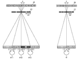
- the required viewpoint number calculation unit 24 calculates the number of required viewpoints N on the basis of the information on the number of viewers which is supplied from the viewer number detection unit 23 . That is, for example, when the number of viewers is one, as shown on the right in FIG. 3 , the number of required viewpoints is total of two-viewpoints of a left eye viewpoint L 1 of a viewer H 1 who is present at a position facing the display direction of the display 65 and the parallax barrier 63 , and a right eye viewpoint R 1 . In this case, it is necessary to have a viewpoint image A as the left eye image, and a viewpoint image B as the right eye image for each of the viewpoints L 1 and R 1 of the viewer H.
- the number of required viewpoints becomes the left eye viewpoints and the right eye viewpoints, respectively, of viewers H 11 to H 13 which are present at a position facing the display 65 and the parallax barrier 63 .
- the viewers H 11 to H 13 are assumed to be present at a regular interval on the face facing the display 65 and the parallax barrier 63 . That is, the viewpoints necessary for the viewer H 11 are the left eye viewpoint L 11 , and the right eye viewpoint R 11 .
- the viewpoints necessary for the viewer H 12 are the left eye viewpoint L 12 , and the right eye viewpoint R 12 .
- the viewpoints necessary for the viewer H 13 are the left eye viewpoint L 13 , and the right eye viewpoint R 13 . Accordingly, in this case, a viewpoint image A is necessary as the left eye image for the viewpoint L 11 of the viewer H 11 , and a viewpoint image B is necessary as the right eye image for the viewpoint R 11 of the viewer H 11 , and as the left eye image for the viewpoint L 12 of the viewer H 12 . In addition, a viewpoint image C is necessary as the right eye image for the viewpoint R 12 of the viewer H 12 , and as the left eye image for the viewpoint L 13 of the viewer H 13 , and viewpoint image D is necessary as the right eye image for the viewpoint R 13 of the viewer H 13 .
- the viewpoint R 11 as the right eye image of the viewer H 11 on the immediate left of the viewer H 12 , and the viewpoint L 12 as the left eye image of the viewer H 12 are the same as each other.
- the viewpoint L 12 as the left eye image of the viewer H 13 on the immediate right of the viewer H 12 , and the viewpoint R 12 as the right eye image of the viewer H 12 are the same as each other.
- the viewpoints of each viewer have a configuration in which the viewpoint of the left eye image is shared with the viewer who is present on the immediate right, and the right eye image is shared with the viewer who is present on the immediate left, respectively.
- all of A to D which are attached onto the display 65 denote the pixel array in which an image corresponding to the viewpoint images A to D are divided into slit shapes in the vertical direction in pixel units.
- the solid line is a light shielding region, and the gap thereof is the slit, and is the transmission region of light which is emitted from the display 65 .
- Q 2 and Q 4 of the parallax barrier 63 in FIG. 3 denote the pitch of the slit (gap) when the number of required viewpoints N are two and four, respectively.
- p denotes the pitch of the pixel (gap).
- step S 5 the two-viewpoint image output unit 42 of the multi-viewpoint image generation unit 26 outputs the right eye image which is supplied from the right eye image obtaining unit 25 - 1 , and the left eye image which is supplied from the left eye image obtaining unit 25 - 2 , as the two-viewpoint image as are to the selection output unit 44 .
- step S 6 the N-viewpoint image generation unit 43 of the multi-viewpoint image generation unit 26 generates an N-viewpoint image according to the number of required viewpoints from the right eye image which is supplied from the right eye image obtaining unit 25 - 1 , and the left eye image which is supplied from the left eye image obtaining unit 25 - 2 .
- the N-viewpoint image generation unit 43 outputs the generated N-viewpoint image to the selection output unit 44 .
- the N-viewpoint image generation unit 43 obtains the viewpoint images A and D, using the extrapolation of the viewpoint images B and C, respectively, since the viewpoint images B and C are the input two-viewpoint images, for example, when the number of required viewpoints is four, as shown on the left portion in FIG. 3 .
- the N-viewpoint image generation unit 43 generates images of new three types of viewpoints, using the interpolation in between the viewpoints A and B, B and C, and C and D, after generating the images of the viewpoints A to D as the four viewpoints.
- the horizontal resolution of each viewpoints image becomes 960 pixels in a case of the two-viewpoint image
- the horizontal resolution of each viewpoints image becomes 480 pixels in a case of the four-viewpoint image.
- the multi-viewpoint image is not formed unnecessarily according to the number of required viewpoints, it is possible to generate the viewpoints image with an appropriate horizontal resolution according to the number of required viewpoints.
- step S 7 the two-viewpoint determination unit 41 determines whether or not the number of required viewpoints N is two.
- step S 7 when the number of required viewpoints N is two in step S 8 , the two-viewpoint determination unit 41 supplies the fact that the number of required viewpoints N is two to the selection output unit 44 .
- the selection output unit 44 supplies the two-viewpoint image as the input image supplied from the two-viewpoint image output unit 42 to the display unit 27 as are, since the determination result supplied from the two-viewpoint determination unit 41 is the two-viewpoint image.
- step S 7 when the number of required viewpoints N is not two, the selection output unit 44 supplies the N-viewpoint image which is supplied from the N-viewpoint image generation unit 43 to the display unit 27 , in step S 9 .
- step S 10 the parallax barrier pitch calculation unit 61 of the display unit 27 calculates the pitch of the slit (gap) in the parallax barrier 63 according to the number of required viewpoints N, and supplies the calculation result to the parallax barrier pitch control unit 62 . More specifically, the pitch of the slit in the parallax barrier 63 is set so as to satisfy the relationship between the following expressions (1) and (2), by the display 65 shown in FIG. 4 , the parallax barrier 63 , and the respective viewpoints images of the viewers H 11 to H 13 .
- e denotes the distance between the left eye and right eye of each viewer
- p denotes a pitch between pixels (gap) of the display 65
- d denotes the distance from the parallax barrier 63 to a measurement position of the viewer
- g denotes the distance between the parallax barrier 63 (slit thereof: opening portion) and the display 65
- Q denotes the pitch of the slit (gap) of the parallax barrier 63
- N denotes the number of required viewpoints.
- the pitch Q of the slit of the parallax barrier is obtained by calculating the following expression (3).
- step S 11 the parallax barrier pitch control unit 62 controls a panel of the parallax barrier 63 , and sets so as to provide the slit at a pitch which is supplied from the parallax barrier pitch calculation unit 61 .
- the slit is set such that a slit is provided at the center portion, and the subsequent slit is provided at a pitch (gap) which is supplied from the parallax barrier pitch calculation unit 61 having the center slit as the reference.
- step S 12 the display pixel array setting unit 64 divides the two-viewpoint image, or the N-viewpoint image which is supplied from the selection output unit 44 into the slit shapes in the unit of pixel column as shown in FIG. 3 , arranges the pixel column so as to reverse the arrangement order in the transverse direction, and displays on the display 65 .
- the viewpoint images A to D are set from the left in FIG. 3 , at a position where the viewers H 11 to H 13 view, in the pixel column array on the display 65 , the image in the line of sight direction corresponding to the viewpoint images A to D which are divided into the slit shapes in the unit of pixel column is repeatedly arranged from images D to A in the order which is transversely reversed.
- the viewers H 11 to H 13 are able to view the three-dimensional stereoscopic image at any position, even when viewing the image displayed on the display unit 27 at different viewpoints, respectively. For this reason, when it is an image with a horizontal resolution of 1920 pixels, if the number of required viewpoints N is four, each viewpoint image becomes 480 pixels, and if the number of required viewpoints N is two, each viewpoint image becomes 960 pixels. That is, since the horizontal resolution with which each viewer views the image varies according to the number of viewers, it is possible to view the stereoscopic image of multi-viewpoints with the appropriate resolution according to the number of viewers.
- the N-viewpoint image is generated and displayed according to the number of required viewpoints which is set by the number of viewers from the two-viewpoint image as the input image, however, when the multi-viewpoint image which is different due to the viewpoint position is generated, the two-viewpoint image corresponding not only to the number of viewers, but to the position of the viewer may be selected and displayed.
- FIG. 5 is a configuration example of a second embodiment of an image processing device in which the two-viewpoint image corresponding not only to the number of viewers, but to the position of the viewer is generated and displayed.
- the image processing device 11 in FIG. 5 regarding the configuration with the same function as that of the image processing device 11 in FIG. 1 will be given with the same name and reference numerals, and descriptions thereof will be omitted.
- the difference from the image processing device 11 in FIG. 1 is that the image processing device 11 in FIG. 5 newly includes a viewer position detection unit 81 .
- an N-viewpoint image generation unit 91 and a selection output unit 92 are provided instead of the N-viewpoint image generation unit 43 and the selection output unit 44 .
- the viewer position detection unit 81 detects positions of a face image which is formed of a rectangular image supplied from a face image detection unit 22 , and a face image which is formed of a rectangular image, on the basis of the inside of the captured image, and detects this as the position of viewers.
- the viewer position detection unit 81 supplies the detected information on the position of viewers to the multi-viewpoint image generation unit 26 .
- the N-viewpoint image generation unit 91 of the multi-viewpoint image generation unit 26 generates a multi-viewpoint image using the right eye image and the left eye image of the two-viewpoint image which corresponds to the position of each viewer, on the basis of the position of the viewer supplied from the viewer position detection unit 81 , and the information on the number of required viewpoints N.
- the N-viewpoint image generation unit 91 supplies to a generated selection output unit 92 .
- the selection output unit 92 has the same basic function as that of the selection output unit 44 , however, outputs the two-viewpoint image which is supplied from a two-viewpoint image output unit 42 to the display unit 27 , only when it is determined as the two-viewpoints by a two-viewpoint determination unit 41 , and further, the viewer is present in the front with respect to the display unit 27 on the basis of the information on the position of the viewer.
- steps S 31 to S 34 , S 36 and, S 40 to S 45 in the flowchart in FIG. 6 are the same as that of steps S 1 to S 5 , and S 8 to S 12 which are described with reference to the flowchart in FIG. 2 , descriptions thereof will be omitted.
- the viewer position detection unit 81 detects the position of the viewer on the basis of the position of the face image in the image which is formed of a rectangular image supplied from the face image detection unit 22 , and supplies the information on the detected position of viewer to the multi-viewpoint image generation unit 26 .
- step S 36 the two-viewpoint image output unit 42 supplies the right eye image and the left eye image which are supplied from a right eye image obtaining unit 25 - 1 and left eye image obtaining unit 25 - 2 to the selection output unit 92 as are.
- step S 37 the N-viewpoint image generation unit 91 generates the two-viewpoint image which corresponds to the position of the viewer, on the basis of the information on the position of the viewer supplied from the viewer position detection unit 81 , and the number of required viewpoints N, and supplies the image to the selection output unit 44 .
- a cylindrical object B 1 with a description of “A” on the upper base, and with a description of “Ko, Sa, Si, Su, Se, So, and Ta” on the side thereof, counterclockwise when viewed from the upper base is displayed.
- the viewers H 11 to H 13 are viewing the object B 1 in the right-hand direction, the front direction, and the left-hand direction, respectively. That is, it matches the positional relationship where the viewers H 11 to H 13 are viewing the display 65 and the parallax barrier 63 , in FIG. 7 .
- the N-viewpoint image generation unit 91 generates a two-viewpoint image in which the object B 1 R on the right in FIG. 8 is stereoscopically viewed, when information on the viewer is supplied at a position where the display 65 and the parallax barrier 63 are viewed in the right-hand direction as the viewer H 11 shown on the left in FIG. 7 , by generating the viewpoint images of A and B shown in FIG. 7 from the two-viewpoint image as the input image using the extrapolation, and supplies to the selection output unit 92 .
- the N-viewpoint image generation unit 91 generates a two-viewpoint image in which the object B 1 C on the right in FIG. 8 is stereoscopically viewed, when information on the viewer is supplied at a position where the display 65 and the parallax barrier 63 are viewed in the front direction as the viewer H 12 shown at the center in FIG. 7 , by generating the viewpoint images of B and C shown in FIG. 7 from the two-viewpoint image as the input image using the extrapolation, and supplies to the selection output unit 92 .
- the N-viewpoint image generation unit 91 generates a two-viewpoint image in which the object B 1 L on the right in FIG. 8 is stereoscopically viewed, when information on the viewer is supplied at a position where the display 65 and the parallax barrier 63 are viewed in the left-hand direction as the viewer H 13 , by generating the viewpoint images of C and D shown in FIG. 7 from the two-viewpoint image as the input image using the extrapolation, and supplies to the selection output unit 92 .
- the object B 1 be viewed as shown in the object B 1 L in which the thick character “Su” which is viewed in the front is viewed as if it is shifted by being rotated to the left, when the object B 1 is viewed in the left-hand direction.
- step S 39 the selection output unit 92 determines whether or not the position of the viewer which is supplied from the viewer position detection unit 81 is the center position. For example, in the step S 39 , when the position of the viewer is the center position, the selection output unit 92 outputs the two-viewpoint image as the input image which is supplied from the two-viewpoint image output unit 42 to the display unit 27 as are, in step S 40 .
- step S 39 when the position of the viewer which is supplied from the viewer position detection unit 81 is not the center position, the selection output unit 92 outputs the N-viewpoint image which is supplied from the N-viewpoint image generation unit 91 to the display unit 27 , in step S 41 .
- the N-viewpoint image generation unit 91 is able to realize the appropriate three-dimensional stereoscopic view for each position of the plurality of viewers, by generating the required two-viewpoint image by the number of viewers at the position of each viewer.
- the multi-viewpoint image can be shared as much as possible when the plurality of viewers can share the multi-viewpoint image, and it is possible to reduce the necessary images as the multi-viewpoint image, degradation of the resolution can be suppressed.
- the multi-viewpoint image when the multi-viewpoint image is generated, it is possible to make the image be viewed as if the positional relationship with the object which is three-dimensionally stereoscopically viewed is also changed, by selecting and displaying the two-viewpoint image corresponding to the viewing position of the viewer with respect to the display 65 and the parallax barrier 63 .
- the example of using the parallax barrier has been described as a configuration of the parallax barrier, however, since the configuration of the parallax barrier may be set according to the number of required viewpoints, it is not limited to the parallax barrier, and may be the lenticular lens.
- FIG. 9 show a configuration example of a third embodiment of the image processing device 11 in which the lenticular lens is used.
- the same number and the same reference numerals are given to a configuration having the same function as that of the image processing device 11 in FIG. 1 , and descriptions thereof will be appropriately omitted.
- the difference from the image processing device 11 in FIG. 1 is that the image processing device 11 in FIG. 9 includes a lenticular lens pitch calculation unit 101 , a lenticular lens pitch control unit 102 , and a lenticular lens 103 instead of the parallax barrier pitch calculation unit 61 , the parallax barrier pitch control unit 62 , and the parallax barrier 63 .
- the lenticular lens 103 is used for the same purpose as the parallax barrier 63 , basically.
- the parallax barrier 63 configures the light shielding region, and configures the parallax barrier by dividing the light transmission region into slits, however, the lenticular lens 103 is configured by a liquid lens on which semi-circular unevenness is provided in the vertical direction. It has the same function as that of changing the pitch of the slit of the parallax barrier, by changing the pitch of the unevenness using a voltage supplied from the lenticular lens pitch control unit 102 .
- the lenticular lens pitch calculation unit 101 calculates the pitch (gap) of the unevenness of the lenticular lens 103 which corresponds to the pitch of the slit calculated by the parallax barrier pitch calculation unit 61 , and supplies the calculation result to the lenticular lens pitch control unit 102 .
- the lenticular lens pitch control unit 102 controls the uneven pitch of the lenticular lens 103 , by generating a corresponding voltage on the basis of the calculation result.
- step S 70 the lenticular lens pitch calculation unit 101 of the display unit 27 calculates the uneven pitch (gap) in the lenticular lens 103 , according to the number of required viewpoints N, and supplies the calculation result to the lenticular lens pitch control unit 102 .
- the calculation method corresponds to the above described expression (3), descriptions thereof will be omitted.
- step S 71 the lenticular lens pitch control unit 102 is set so as to provide the uneven portion at a pitch supplied from the lenticular lens pitch calculation unit 101 , by controlling an applied voltage of the lenticular lens 103 .
- the lenticular lens 103 has higher light intensity to be transmitted than the parallax barrier 63 , it is possible for the viewer to view bright stereoscopic image to that extent. Further, similarly to the image processing device 11 in FIG.
- the present technology it is possible to display the multi-viewpoint image with the appropriate resolution corresponding to the number of viewers.
- the above described series of processing can be executed using hardware, however, it can be executed using software, as well.
- a program configuring the software is installed to a computer built into dedicated hardware, or, for example, a general-purpose personal computer which can execute a variety of functions, by installing a variety of programs, or the like, from a recording medium.
- FIG. 11 shows a configuration example of a general-purpose personal computer.
- the personal computer includes a built-in CPU (Central Processing Unit (i.e., hardware processor) 1001 .
- the CPU 1001 is connected with an input/output interface 1005 through a bus 1004 .
- the bus 1004 is connected with a ROM (Read Only Memory (i.e., storage medium) 1002 and a RAM (Random Access Memory) 1003 .
- ROM Read Only Memory
- RAM Random Access Memory
- a magnetic disk including flexible disk
- an optical disc including CD-ROM (Compact Disc-Read Only Memory), and DVD (Digital Versatile Disc)
- a magneto-optical disc including MD (Mini Disc)
- a drive 1010 which reads and writes data with respect to a removable media 1011 such as semiconductor memory is connected to the input/output interface.
- the CPU 1001 executes various processing according to a program (i.e., instructions) stored in the ROM 1002 , or a variety of programs (i.e., instructions) which are read out from the magnetic disk, optical disc, magneto-optical disc, or the removable media 1011 such as the semiconductor memory (any of which constitutes a non-transitory, computer-readable storage medium), are installed in the storage unit 1008 , and are loaded to the RAM 1003 from the storage unit 1008 .
- the RAM 1003 appropriately stores data or the like, which is necessary when the CPU 1001 executes various processing.
- the step of describing a program which is recorded in a recording medium includes processing which is executed individually, or in parallel as well, even if they are not necessarily processed in time series, and it is needless to say to include processing which is performed in time series according to the described order.
- the present technology may have a configuration described below.
- An apparatus comprising:
- a storage medium coupled to the processor and storing instructions that, when executed by the processor, cause the apparatus to:
- the storage medium stores instructions that, when executed by the processor, cause the apparatus to generate the plurality of images by one of interpolating or extrapolating the plurality of images from other images.
Abstract
An apparatus may include a hardware processor and a storage medium. The storage medium may be coupled to the processor, and may store instructions. When executed by the processor, the instructions may cause the apparatus to determine a number of viewers. The instructions may also cause the apparatus to calculate a number of viewpoints based on the number of viewers. Additionally, the instructions may cause the apparatus to generate a plurality of images corresponding to the viewpoints.
Description
- The present technology relates to an image processing device and method thereof, and a program, and particularly, to an image processing device and method thereof, and a program in which multi-viewpoint images can be viewed at an appropriate resolution corresponding to the number of viewers, when a glasses-free three-dimensional stereoscopic image with two viewpoints, which is an input image, is input.
- As a glasses-free image display device in which stereoscopic images can be viewed without using special glasses, a parallax barrier system (for example, refer to PTL 1) or a lenticular lens system (for example, refer to PTL 2) is well known.
-
- PTL 1: PTL 1: Japanese Unexamined Patent Application Publication No. 7-5420
- PTL 2: Japanese Unexamined Patent Application Publication No. 5-49044
- Meanwhile, in both cases of the above described two-lens parallax barrier system, or the lenticular system, since pixels are divided into a right eye pixel and a left eye pixel, and display a right eye image and a left eye image respectively, the resolution thereof is halved. For this reason, when it is configured to be viewed from multiple viewpoints so as to correspond to the direction of view of more multiple viewers, the resolution thereof is further reduced.
- However, there may be a case where a single viewer views images with low resolution by enabling viewing from multiple viewpoints, for example, regardless of there being only one viewer, and when viewing from multiple viewpoints is not necessarily needed.
- The present technology has been made in view of this situation, and particularly, is to enable viewing images from multiple viewpoints at the appropriate resolution corresponding to the number of viewers, when glasses-free three-dimensional stereoscopic image with two viewpoints as the input image is input.
- There is disclosed an apparatus, which may include a hardware processor and a storage medium. The storage medium may be coupled to the processor, and may store instructions. When executed by the processor, the instructions may cause the apparatus to determine a number of viewers. The instructions may also cause the apparatus to calculate a number of viewpoints based on the number of viewers. Additionally, the instructions may cause the apparatus to generate a plurality of images corresponding to the viewpoints.
- There is also disclosed a method. The method may include determining a number of viewers. The method may also include calculating a number of viewpoints based on the number of viewers. Additionally, the method may include generating a plurality of images corresponding to the viewpoints.
- In addition, there is disclosed a non-transitory, computer-readable storage medium storing instructions. When executed by a processor, the instructions may cause an apparatus to determine a number of viewers. The instructions may also cause the apparatus to calculate a number of viewpoints based on the number of viewers. Additionally, the instructions may cause the apparatus to generate a plurality of images corresponding to the viewpoints.
-
FIG. 1 is a block diagram which shows a configuration example of a first embodiment of an image processing device to which the present technology is applied. -
FIG. 2 is a flowchart which describes display processing of a multi-viewpoint image according to the image processing device inFIG. 1 . -
FIG. 3 is a diagram which describes the display processing of the multi-viewpoint image. -
FIG. 4 is a diagram which describes a method of calculating the pitch of a slit of a parallax barrier. -
FIG. 5 is a block diagram which shows a configuration example of a second embodiment of the image processing device. -
FIG. 6 is a flowchart which describes a display processing of a multi-viewpoint image according to the image processing device inFIG. 5 . -
FIG. 7 is a diagram which describes the display processing of the multi-viewpoint image which corresponds to a position of a viewer. -
FIG. 8 is a diagram which describes a display example of the multi-viewpoint image which corresponds to the position of the viewer. -
FIG. 9 is a block diagram which shows a configuration example of a third embodiment of the image processing device. -
FIG. 10 is a flowchart which describes display processing of the multi-viewpoint image according to the image processing device inFIG. 9 . -
FIG. 11 is a diagram which describes a configuration example of a general-purpose personal computer. - Hereinafter, embodiments for embodying the present technology (hereinafter, referred to as “embodiment”) will be described. In addition, the description will be made in the following order.
- 1. First embodiment (an example where parallax barrier is used)
- 2. Second embodiment (an example where position information of viewer is used)
- 3. Third embodiment (an example where lenticular lens is used)
-
FIG. 1 shows a configuration example of a first embodiment of an image processing device to which the present technology is applied. Theimage processing device 11 inFIG. 1 displays an image which can be viewed as three-dimensional stereoscopic image using the naked eye with a predetermined parallax, which is an input image of a right eye image and left eye image, as a multi-viewpoint image at an appropriate resolution based on the number of viewers, and is a TV receiver, or the like. - The
image processing device 11 inFIG. 1 , includes an imaging unit (i.e., a software module, a hardware module, or a combination of a software module and a hardware module) 21, a faceimage detection unit 22, a viewernumber detection unit 23, a required viewpointnumber calculation unit 24, a right eye image obtaining unit 25-1, left eye image obtaining unit 25-2, a multi-viewpointimage generation unit 26, and adisplay unit 27. - The
imaging unit 21 captures an image in the direction in which a viewer views an image which is displayed by the image processing device 11 (i.e., a viewer image), and supplies the image to the faceimage detection unit 22. - The face
image detection unit 22 extracts information on facial contour of a human body, or eyes, ears, a nose, a mouth, or the like as organs, as a detectable feature amount from the supplied image, specifies as a rectangular face image, and supplies the specified face image to the viewernumber detection unit 23 along with the captured image. - The viewer
number detection unit 23 obtains the number of obtained face images, detects this as the number of viewers, and supplies the information on the number of viewers as the detection result to the required viewpointnumber calculation unit 24, when the face image which is supplied from the faceimage detection unit 22 is obtained. - The required viewpoint
number calculation unit 24 calculates the number of required viewpoints which is required when configuring a multi-viewpoint image on the basis of the information on the number of viewers which is supplied from viewernumber detection unit 23, and supplies the number of required viewpoints to the multi-viewpointimage generation unit 26, and thedisplay unit 27. The viewer is assumed to be present at a regular interval in the horizontal direction with respect to the displayed image. In addition, in order to make the viewer be able to view a three-dimensional stereoscopic image, a left eye image and a right eye image are set, respectively, for each viewer. In addition, a second viewer who is present on the left side of the first viewer uses the left eye image of the first viewer as his own right eye image. Further, similarly to this, a third viewer who is present on the right side of the first viewer uses the right eye image of the first viewer as his own left eye image. Accordingly, for example, when the viewers are three, the required number of viewpoints is four. - The right eye image obtaining unit 25-1, and the left eye image obtaining unit 25-2 respectively obtains the input right eye image and left eye image which are three-dimensional and stereoscopic, supplies the images to the multi-viewpoint
image generation unit 26. - The multi-viewpoint
image generation unit 26 generates a multi-viewpoint image from the input right eye image and left eye image which are supplied from the right eye image obtaining unit 25-1, and the left eye image obtaining unit 25-2, on the basis of the information on the number of required viewpoints which is supplied from the required viewpointnumber calculation unit 24, and supplies the image to thedisplay unit 27. - More specifically, the multi-viewpoint
image generation unit 26 is configured by a two-viewpoint determination unit 41, a two-viewpointimage output unit 42, an N-viewpointimage generation unit 43, and aselection output unit 44. The two-viewpoint determination unit 41 determines whether or not the number of required viewpoints which is supplied from the required viewpointnumber calculation unit 24 is two-viewpoints, and supplies the determination result to theselection output unit 44. The two-viewpointimage output unit 42 supplies the right eye image and the left eye image, which are supplied from the right eye image obtaining unit 25-1, and the left eye image obtaining unit 25-2 as are to theselection output unit 44. The N-viewpointimage generation unit 43 generates images by the number of required viewpoints using an interpolation or extrapolation, by controlling aninterpolation generation unit 43 a, using the right eye image and the left eye image (i.e., other images), which are supplied from the right eye image obtaining unit 25-1, and the left eye image obtaining unit 25-2, on the basis of the information on the number of required viewpoints which is supplied from the required viewpointnumber calculation unit 24, and supplies the image to theselection output unit 44. Theselection output unit 44 outputs the two-viewpoint image which is formed of the right eye image and the left eye image which are supplied from the two-viewpointimage output unit 42 to thedisplay unit 27 as they are, when the number of required viewpoints is two, on the basis of the determination result which is supplied from the two-viewpoint determination unit 41. On the other hand, when the number of required viewpoints is not two, theselection output unit 44 outputs the multi-viewpoint image which is generated by the N-viewpointimage generation unit 43 to thedisplay unit 27, on the basis of the determination result which is supplied from the two-viewpoint determination unit 41. - The
display unit 27 controls a pitch (the gap) of a slit of aparallax barrier 63, on the basis of the information on the number of required viewpoints which is supplied from the required viewpointnumber calculation unit 24, displays the two-viewpoint image which is supplied from the multi-viewpointimage generation unit 26, or the multi-viewpoint image, and displays the multi-viewpoint image through theparallax barrier 63. - More specifically, the
display unit 27 includes a parallax barrierpitch calculation unit 61, a parallax barrierpitch control unit 62, theparallax barrier 63, a display pixelarray setting unit 64, and adisplay 65. The parallax barrierpitch calculation unit 61 calculates the slit with the pitch (the gap of slit) in the vertical direction in which light which is emitted from thedisplay 65 is transmitted using theparallax barrier 63, according to the number of required viewpoints which is calculated by the required viewpointnumber calculation unit 24, and supplies the pitch to the parallax barrierpitch control unit 62. The parallax barrierpitch control unit 62 controls the operation of theparallax barrier 63 so as to configure the slit in the corresponding vertical direction, on the basis of the pitch (the gap of slit) of the parallax barrier which is calculated by the parallax barrierpitch calculation unit 61. - The
parallax barrier 63 is formed of, for example, a liquid crystal panel or the like, and configures slits in the vertical direction at a pitch which is controlled by the parallax barrierpitch control unit 62. More specifically, theparallax barrier 63, for example, configures a shielding region with respect to a region other than a region which configures the vertical slit using liquid crystal, configures a parallax barrier by setting only the slit region as a light transmission region, and functions as the parallax barrier. The display pixelarray setting unit 64 separates the generated multi-viewpoint image to slit shapes in a unit of pixel column, according to the number of required viewpoints which is supplied from the required viewpointnumber calculation unit 24, arranges the multi-viewpoint image with the slit shape in the reverse direction with respect to the line of sight direction, and displays on thedisplay 65. Thedisplay 65 is formed of a liquid crystal display (LCD), a plasma display, an organic EL, or the like, and displays an image by causing colors to be emitted using a pixel value which is supplied from the display pixelarray setting unit 64. - Subsequently, display processing of the multi-viewpoint image by an
image processing device 11 inFIG. 1 will be described with reference to the flowchart inFIG. 2 . - In step S1, the
imaging unit 21 captures an image in the direction in which the viewer is present, that is, in the direction facing the image which is displayed by thedisplay unit 27, and supplies the captured image to the faceimage detection unit 22. - In step S2, the face
image detection unit 22 detects a rectangular face image by extracting a feature amount which is required when detecting the face image from the supplied image, and supplies the rectangular face image to the viewernumber detection unit 23 along with the captured image. - In step S3, the viewer
number detection unit 23 detects the number of viewers on the basis of the number of the supplied face images, and supplies the detected information on the number of viewers to the required viewpointnumber calculation unit 24. - In step S4, the required viewpoint
number calculation unit 24 calculates the number of required viewpoints N on the basis of the information on the number of viewers which is supplied from the viewernumber detection unit 23. That is, for example, when the number of viewers is one, as shown on the right inFIG. 3 , the number of required viewpoints is total of two-viewpoints of a left eye viewpoint L1 of a viewer H1 who is present at a position facing the display direction of thedisplay 65 and theparallax barrier 63, and a right eye viewpoint R1. In this case, it is necessary to have a viewpoint image A as the left eye image, and a viewpoint image B as the right eye image for each of the viewpoints L1 and R1 of the viewer H. On the other hand, as shown on the left inFIG. 3 , when the number of viewers is three, the number of required viewpoints becomes the left eye viewpoints and the right eye viewpoints, respectively, of viewers H11 to H13 which are present at a position facing thedisplay 65 and theparallax barrier 63. Here, the viewers H11 to H13 are assumed to be present at a regular interval on the face facing thedisplay 65 and theparallax barrier 63. That is, the viewpoints necessary for the viewer H11 are the left eye viewpoint L11, and the right eye viewpoint R11. In addition, the viewpoints necessary for the viewer H12 are the left eye viewpoint L12, and the right eye viewpoint R12. Further, the viewpoints necessary for the viewer H13 are the left eye viewpoint L13, and the right eye viewpoint R13. Accordingly, in this case, a viewpoint image A is necessary as the left eye image for the viewpoint L11 of the viewer H11, and a viewpoint image B is necessary as the right eye image for the viewpoint R11 of the viewer H11, and as the left eye image for the viewpoint L12 of the viewer H12. In addition, a viewpoint image C is necessary as the right eye image for the viewpoint R12 of the viewer H12, and as the left eye image for the viewpoint L13 of the viewer H13, and viewpoint image D is necessary as the right eye image for the viewpoint R13 of the viewer H13. - That is, when considering the viewer H12 as a reference, the viewpoint R11 as the right eye image of the viewer H11 on the immediate left of the viewer H12, and the viewpoint L12 as the left eye image of the viewer H12 are the same as each other. In addition, the viewpoint L12 as the left eye image of the viewer H13 on the immediate right of the viewer H12, and the viewpoint R12 as the right eye image of the viewer H12 are the same as each other.
- As a result, when the number of viewers is three, the required number of viewpoints N becomes four. In addition, even when the number of viewers is different from this, the viewpoints of each viewer have a configuration in which the viewpoint of the left eye image is shared with the viewer who is present on the immediate right, and the right eye image is shared with the viewer who is present on the immediate left, respectively. In addition, in
FIG. 3 , all of A to D which are attached onto thedisplay 65 denote the pixel array in which an image corresponding to the viewpoint images A to D are divided into slit shapes in the vertical direction in pixel units. In addition, in theparallax barrier 63, the solid line is a light shielding region, and the gap thereof is the slit, and is the transmission region of light which is emitted from thedisplay 65. Further, Q2 and Q4 of theparallax barrier 63 inFIG. 3 denote the pitch of the slit (gap) when the number of required viewpoints N are two and four, respectively. In thedisplay 65, p denotes the pitch of the pixel (gap). - In step S5, the two-viewpoint
image output unit 42 of the multi-viewpointimage generation unit 26 outputs the right eye image which is supplied from the right eye image obtaining unit 25-1, and the left eye image which is supplied from the left eye image obtaining unit 25-2, as the two-viewpoint image as are to theselection output unit 44. - In step S6, the N-viewpoint
image generation unit 43 of the multi-viewpointimage generation unit 26 generates an N-viewpoint image according to the number of required viewpoints from the right eye image which is supplied from the right eye image obtaining unit 25-1, and the left eye image which is supplied from the left eye image obtaining unit 25-2. In addition, the N-viewpointimage generation unit 43 outputs the generated N-viewpoint image to theselection output unit 44. - More specifically, the N-viewpoint
image generation unit 43 obtains the viewpoint images A and D, using the extrapolation of the viewpoint images B and C, respectively, since the viewpoint images B and C are the input two-viewpoint images, for example, when the number of required viewpoints is four, as shown on the left portion inFIG. 3 . In addition, when the number of required viewpoints is three, as shown on the left portion inFIG. 3 , the N-viewpointimage generation unit 43 generates images of new three types of viewpoints, using the interpolation in between the viewpoints A and B, B and C, and C and D, after generating the images of the viewpoints A to D as the four viewpoints. In addition, when the horizontal resolution of the input image is 1920 pixels, the horizontal resolution of each viewpoints image becomes 960 pixels in a case of the two-viewpoint image, and further, the horizontal resolution of each viewpoints image becomes 480 pixels in a case of the four-viewpoint image. However, since the multi-viewpoint image is not formed unnecessarily according to the number of required viewpoints, it is possible to generate the viewpoints image with an appropriate horizontal resolution according to the number of required viewpoints. - In step S7, the two-
viewpoint determination unit 41 determines whether or not the number of required viewpoints N is two. In step S7, when the number of required viewpoints N is two in step S8, the two-viewpoint determination unit 41 supplies the fact that the number of required viewpoints N is two to theselection output unit 44. Theselection output unit 44 supplies the two-viewpoint image as the input image supplied from the two-viewpointimage output unit 42 to thedisplay unit 27 as are, since the determination result supplied from the two-viewpoint determination unit 41 is the two-viewpoint image. - On the other hand, in step S7, when the number of required viewpoints N is not two, the
selection output unit 44 supplies the N-viewpoint image which is supplied from the N-viewpointimage generation unit 43 to thedisplay unit 27, in step S9. - In step S10, the parallax barrier
pitch calculation unit 61 of thedisplay unit 27 calculates the pitch of the slit (gap) in theparallax barrier 63 according to the number of required viewpoints N, and supplies the calculation result to the parallax barrierpitch control unit 62. More specifically, the pitch of the slit in theparallax barrier 63 is set so as to satisfy the relationship between the following expressions (1) and (2), by thedisplay 65 shown inFIG. 4 , theparallax barrier 63, and the respective viewpoints images of the viewers H11 to H13. -
e:p=d:g (1) -
Q:d=N×p:(d+g) (2) - Here, e denotes the distance between the left eye and right eye of each viewer, and p denotes a pitch between pixels (gap) of the
display 65, d denotes the distance from theparallax barrier 63 to a measurement position of the viewer, and g denotes the distance between the parallax barrier 63 (slit thereof: opening portion) and thedisplay 65. In addition, Q denotes the pitch of the slit (gap) of theparallax barrier 63, and N denotes the number of required viewpoints. - As a result, the pitch Q of the slit of the parallax barrier is obtained by calculating the following expression (3).
-
Q=(d×N×p)/(d+g) (3) - In step S11, the parallax barrier
pitch control unit 62 controls a panel of theparallax barrier 63, and sets so as to provide the slit at a pitch which is supplied from the parallax barrierpitch calculation unit 61. At this time, in theparallax barrier 63, the slit is set such that a slit is provided at the center portion, and the subsequent slit is provided at a pitch (gap) which is supplied from the parallax barrierpitch calculation unit 61 having the center slit as the reference. - In step S12, the display pixel
array setting unit 64 divides the two-viewpoint image, or the N-viewpoint image which is supplied from theselection output unit 44 into the slit shapes in the unit of pixel column as shown inFIG. 3 , arranges the pixel column so as to reverse the arrangement order in the transverse direction, and displays on thedisplay 65. - That is, for example, as shown on the left in
FIG. 3 , when the viewpoint images A to D are set from the left inFIG. 3 , at a position where the viewers H11 to H13 view, in the pixel column array on thedisplay 65, the image in the line of sight direction corresponding to the viewpoint images A to D which are divided into the slit shapes in the unit of pixel column is repeatedly arranged from images D to A in the order which is transversely reversed. - According to the above described processing, the viewers H11 to H13 are able to view the three-dimensional stereoscopic image at any position, even when viewing the image displayed on the
display unit 27 at different viewpoints, respectively. For this reason, when it is an image with a horizontal resolution of 1920 pixels, if the number of required viewpoints N is four, each viewpoint image becomes 480 pixels, and if the number of required viewpoints N is two, each viewpoint image becomes 960 pixels. That is, since the horizontal resolution with which each viewer views the image varies according to the number of viewers, it is possible to view the stereoscopic image of multi-viewpoints with the appropriate resolution according to the number of viewers. - As described above, an example where the N-viewpoint image is generated and displayed according to the number of required viewpoints which is set by the number of viewers from the two-viewpoint image as the input image, however, when the multi-viewpoint image which is different due to the viewpoint position is generated, the two-viewpoint image corresponding not only to the number of viewers, but to the position of the viewer may be selected and displayed.
-
FIG. 5 is a configuration example of a second embodiment of an image processing device in which the two-viewpoint image corresponding not only to the number of viewers, but to the position of the viewer is generated and displayed. In addition, in theimage processing device 11 inFIG. 5 , regarding the configuration with the same function as that of theimage processing device 11 inFIG. 1 will be given with the same name and reference numerals, and descriptions thereof will be omitted. - That is, in the
image processing device 11 inFIG. 5 , the difference from theimage processing device 11 inFIG. 1 is that theimage processing device 11 inFIG. 5 newly includes a viewerposition detection unit 81. In addition, in a multi-viewpointimage generation unit 26, an N-viewpointimage generation unit 91 and aselection output unit 92 are provided instead of the N-viewpointimage generation unit 43 and theselection output unit 44. - The viewer
position detection unit 81 detects positions of a face image which is formed of a rectangular image supplied from a faceimage detection unit 22, and a face image which is formed of a rectangular image, on the basis of the inside of the captured image, and detects this as the position of viewers. The viewerposition detection unit 81 supplies the detected information on the position of viewers to the multi-viewpointimage generation unit 26. - The N-viewpoint
image generation unit 91 of the multi-viewpointimage generation unit 26 generates a multi-viewpoint image using the right eye image and the left eye image of the two-viewpoint image which corresponds to the position of each viewer, on the basis of the position of the viewer supplied from the viewerposition detection unit 81, and the information on the number of required viewpoints N. In addition, the N-viewpointimage generation unit 91 supplies to a generatedselection output unit 92. - The
selection output unit 92 has the same basic function as that of theselection output unit 44, however, outputs the two-viewpoint image which is supplied from a two-viewpointimage output unit 42 to thedisplay unit 27, only when it is determined as the two-viewpoints by a two-viewpoint determination unit 41, and further, the viewer is present in the front with respect to thedisplay unit 27 on the basis of the information on the position of the viewer. - Subsequently, display processing of the multi-viewpoint image by the
image processing device 11 inFIG. 5 will be described with reference to the flowchart inFIG. 6 . In addition, processing of steps S31 to S34, S36 and, S40 to S45 in the flowchart inFIG. 6 are the same as that of steps S1 to S5, and S8 to S12 which are described with reference to the flowchart inFIG. 2 , descriptions thereof will be omitted. - That is, when the number of required viewpoints is obtained by the processing of steps S31 to S34, in step S35, the viewer
position detection unit 81 detects the position of the viewer on the basis of the position of the face image in the image which is formed of a rectangular image supplied from the faceimage detection unit 22, and supplies the information on the detected position of viewer to the multi-viewpointimage generation unit 26. - In step S36, the two-viewpoint
image output unit 42 supplies the right eye image and the left eye image which are supplied from a right eye image obtaining unit 25-1 and left eye image obtaining unit 25-2 to theselection output unit 92 as are. - In step S37, the N-viewpoint
image generation unit 91 generates the two-viewpoint image which corresponds to the position of the viewer, on the basis of the information on the position of the viewer supplied from the viewerposition detection unit 81, and the number of required viewpoints N, and supplies the image to theselection output unit 44. - That is, when the viewer is one, for example, viewers H11 to H13 who are present on the left, at the center, and on the right in
FIG. 7 are viewing theparallax barrier 63 and thedisplay 65 in the different direction from each other, respectively. That is, the viewers H11 to H13 view theparallax barrier 63 and thedisplay 65 in the right-hand direction, the front direction, and the left-hand direction from their own position, respectively. It is assumed that a multi-viewpoint image is obtained in a multi-viewpoint image obtaining unit 82 at a position where thedisplay 65 and theparallax barrier 63 are present, in which, for example, as shown on the left inFIG. 8 , a cylindrical object B1 with a description of “A” on the upper base, and with a description of “Ko, Sa, Si, Su, Se, So, and Ta” on the side thereof, counterclockwise when viewed from the upper base is displayed. In this case, as shown on the left inFIG. 8 , the viewers H11 to H13 are viewing the object B1 in the right-hand direction, the front direction, and the left-hand direction, respectively. That is, it matches the positional relationship where the viewers H11 to H13 are viewing thedisplay 65 and theparallax barrier 63, inFIG. 7 . - Therefore, the N-viewpoint
image generation unit 91 generates a two-viewpoint image in which the object B1R on the right inFIG. 8 is stereoscopically viewed, when information on the viewer is supplied at a position where thedisplay 65 and theparallax barrier 63 are viewed in the right-hand direction as the viewer H11 shown on the left inFIG. 7 , by generating the viewpoint images of A and B shown inFIG. 7 from the two-viewpoint image as the input image using the extrapolation, and supplies to theselection output unit 92. - In addition, the N-viewpoint
image generation unit 91 generates a two-viewpoint image in which the object B1C on the right inFIG. 8 is stereoscopically viewed, when information on the viewer is supplied at a position where thedisplay 65 and theparallax barrier 63 are viewed in the front direction as the viewer H12 shown at the center inFIG. 7 , by generating the viewpoint images of B and C shown inFIG. 7 from the two-viewpoint image as the input image using the extrapolation, and supplies to theselection output unit 92. - In addition, the N-viewpoint
image generation unit 91 generates a two-viewpoint image in which the object B1L on the right inFIG. 8 is stereoscopically viewed, when information on the viewer is supplied at a position where thedisplay 65 and theparallax barrier 63 are viewed in the left-hand direction as the viewer H13, by generating the viewpoint images of C and D shown inFIG. 7 from the two-viewpoint image as the input image using the extrapolation, and supplies to theselection output unit 92. - For this reason, as shown in
FIG. 8 , for the viewer H11 who is viewing thedisplay 65 and theparallax barrier 63 in the right-hand direction, as in a case where the object B1 is viewed in the right-hand direction, it is possible make the object B1 be viewed as shown in the object B1R in which the thick character “Su” which is viewed in the front is viewed as if it is shifted by being rotated to the right, when the object B1 is viewed in the right-hand direction. In addition, for the viewer H12 who is viewing thedisplay 65 and theparallax barrier 63 in the front direction, as in a case where the object B1 is viewed in the front direction, it is possible make the thick character “Su” be viewed in the front as shown in the object B1C, when the object B1 is viewed in the front direction. Further, for the viewer H13 who is viewing thedisplay 65 and theparallax barrier 63 in the left-hand direction, as in a case where the object B1 is viewed in the left-hand direction, it is possible make the object B1 be viewed as shown in the object B1L in which the thick character “Su” which is viewed in the front is viewed as if it is shifted by being rotated to the left, when the object B1 is viewed in the left-hand direction. - In addition, in step S38, when the number of required viewpoints is two, in step S39, the
selection output unit 92 determines whether or not the position of the viewer which is supplied from the viewerposition detection unit 81 is the center position. For example, in the step S39, when the position of the viewer is the center position, theselection output unit 92 outputs the two-viewpoint image as the input image which is supplied from the two-viewpointimage output unit 42 to thedisplay unit 27 as are, in step S40. In addition, in step S39, when the position of the viewer which is supplied from the viewerposition detection unit 81 is not the center position, theselection output unit 92 outputs the N-viewpoint image which is supplied from the N-viewpointimage generation unit 91 to thedisplay unit 27, in step S41. - As a result, it is possible to realize the three-dimensional stereoscopic view corresponding to the direction in which the viewer is viewing, in the
display 65 and theparallax barrier 63. In addition, when the plurality of viewers are present at a separated position, the N-viewpointimage generation unit 91 is able to realize the appropriate three-dimensional stereoscopic view for each position of the plurality of viewers, by generating the required two-viewpoint image by the number of viewers at the position of each viewer. In this case, since the multi-viewpoint image can be shared as much as possible when the plurality of viewers can share the multi-viewpoint image, and it is possible to reduce the necessary images as the multi-viewpoint image, degradation of the resolution can be suppressed. - As described above, when the multi-viewpoint image is generated, it is possible to make the image be viewed as if the positional relationship with the object which is three-dimensionally stereoscopically viewed is also changed, by selecting and displaying the two-viewpoint image corresponding to the viewing position of the viewer with respect to the
display 65 and theparallax barrier 63. - As described above, the example of using the parallax barrier has been described as a configuration of the parallax barrier, however, since the configuration of the parallax barrier may be set according to the number of required viewpoints, it is not limited to the parallax barrier, and may be the lenticular lens.
-
FIG. 9 show a configuration example of a third embodiment of theimage processing device 11 in which the lenticular lens is used. In addition, inFIG. 9 , the same number and the same reference numerals are given to a configuration having the same function as that of theimage processing device 11 inFIG. 1 , and descriptions thereof will be appropriately omitted. - That is, in the
image processing device 11 inFIG. 9 , the difference from theimage processing device 11 inFIG. 1 is that theimage processing device 11 inFIG. 9 includes a lenticular lenspitch calculation unit 101, a lenticular lenspitch control unit 102, and alenticular lens 103 instead of the parallax barrierpitch calculation unit 61, the parallax barrierpitch control unit 62, and theparallax barrier 63. - The
lenticular lens 103 is used for the same purpose as theparallax barrier 63, basically. Theparallax barrier 63 configures the light shielding region, and configures the parallax barrier by dividing the light transmission region into slits, however, thelenticular lens 103 is configured by a liquid lens on which semi-circular unevenness is provided in the vertical direction. It has the same function as that of changing the pitch of the slit of the parallax barrier, by changing the pitch of the unevenness using a voltage supplied from the lenticular lenspitch control unit 102. - The lenticular lens
pitch calculation unit 101 calculates the pitch (gap) of the unevenness of thelenticular lens 103 which corresponds to the pitch of the slit calculated by the parallax barrierpitch calculation unit 61, and supplies the calculation result to the lenticular lenspitch control unit 102. - The lenticular lens
pitch control unit 102 controls the uneven pitch of thelenticular lens 103, by generating a corresponding voltage on the basis of the calculation result. - Subsequently, display processing of the multi-viewpoint image using image processing device in
FIG. 9 will be described with reference to the flowchart inFIG. 10 . In addition, processing of the steps S61 to S69, and S72 in the flowchart inFIG. 10 are the same as those of the steps S1 to S9, and S12 in the flowchart inFIG. 2 , descriptions thereof will be omitted. - That is, when the multi-viewpoint image, or the two-viewpoint image is supplied to the
display unit 27 by the processing of step S61 to S69, in step S70, the lenticular lenspitch calculation unit 101 of thedisplay unit 27 calculates the uneven pitch (gap) in thelenticular lens 103, according to the number of required viewpoints N, and supplies the calculation result to the lenticular lenspitch control unit 102. In addition, the calculation method corresponds to the above described expression (3), descriptions thereof will be omitted. - In step S71, the lenticular lens
pitch control unit 102 is set so as to provide the uneven portion at a pitch supplied from the lenticular lenspitch calculation unit 101, by controlling an applied voltage of thelenticular lens 103. - According to the above described processing, it is possible to exert the same effect as that of the
image processing device 11 inFIG. 1 , even if thelenticular lens 103 is used instead of theparallax barrier 63. In addition, thelenticular lens 103 has higher light intensity to be transmitted than theparallax barrier 63, it is possible for the viewer to view bright stereoscopic image to that extent. Further, similarly to theimage processing device 11 inFIG. 5 , it is possible to display the two-viewpoint image corresponding to the position of the viewer, by providing the viewerposition detection unit 81, and by providing the N-viewpointimage generation unit 91 and theselection output unit 92 instead of the N-viewpointimage generation unit 43 and theselection output unit 44, in theimage processing device 11 inFIG. 9 . - As described above, according to the present technology, it is possible to display the multi-viewpoint image with the appropriate resolution corresponding to the number of viewers.
- Meanwhile, the above described series of processing can be executed using hardware, however, it can be executed using software, as well. When the series of processing is executed using the software, a program configuring the software is installed to a computer built into dedicated hardware, or, for example, a general-purpose personal computer which can execute a variety of functions, by installing a variety of programs, or the like, from a recording medium.
-
FIG. 11 shows a configuration example of a general-purpose personal computer. The personal computer includes a built-in CPU (Central Processing Unit (i.e., hardware processor) 1001. TheCPU 1001 is connected with an input/output interface 1005 through abus 1004. Thebus 1004 is connected with a ROM (Read Only Memory (i.e., storage medium) 1002 and a RAM (Random Access Memory) 1003. - The input/
output interface 1005 is connected with a keyboard for inputting an operation command by a user, aninput unit 1006 formed of an input device such as a mouse, anoutput unit 1007 for outputting an image of a processing operation screen or a processing result to a display device, astorage unit 1008 which is formed of a hard disk drive or the like for storing programs, or various data, and acommunication unit 1009 which is formed of a LAN (Local Area Network) adapter or the like, and executes communication processing through a network which is represented by the Internet. In addition, a magnetic disk (including flexible disk), an optical disc (including CD-ROM (Compact Disc-Read Only Memory), and DVD (Digital Versatile Disc), a magneto-optical disc (including MD (Mini Disc), or adrive 1010 which reads and writes data with respect to aremovable media 1011 such as semiconductor memory is connected to the input/output interface. - The
CPU 1001 executes various processing according to a program (i.e., instructions) stored in theROM 1002, or a variety of programs (i.e., instructions) which are read out from the magnetic disk, optical disc, magneto-optical disc, or theremovable media 1011 such as the semiconductor memory (any of which constitutes a non-transitory, computer-readable storage medium), are installed in thestorage unit 1008, and are loaded to theRAM 1003 from thestorage unit 1008. In addition, theRAM 1003 appropriately stores data or the like, which is necessary when theCPU 1001 executes various processing. - In addition, in the application, the step of describing a program which is recorded in a recording medium includes processing which is executed individually, or in parallel as well, even if they are not necessarily processed in time series, and it is needless to say to include processing which is performed in time series according to the described order.
- In addition, the present technology may have a configuration described below.
- (1) An apparatus, comprising:
- a hardware processor; and
- a storage medium coupled to the processor and storing instructions that, when executed by the processor, cause the apparatus to:
- determine a number of viewers;
- calculate a number of viewpoints based on the number of viewers; and
- generate a plurality of images corresponding to the viewpoints.
- (2) The apparatus of (1), wherein the storage medium stores instructions that, when executed by the processor, cause the apparatus to output the plurality of images to a display.
- (3) The apparatus of (2), comprising the display.
- (4) The apparatus of any one of (1) to (3), wherein the storage medium stores instructions that, when executed by the processor, cause the apparatus to generate the plurality of images from a left-eye image and a right-eye image.
- (5) The apparatus of any one of (1) to (4), wherein the storage medium stores instructions that, when executed by the processor, cause the apparatus to determine the number of viewers based on a viewer image.
- (6) The apparatus of (5), wherein the storage medium stores instructions that, when executed by the processor, cause the apparatus to determine the number of viewers by detecting a number of faces in the viewer image.
- (7) The apparatus of (5) or (6), comprising an imaging unit for capturing the viewer image.
- (8) The apparatus of any one of (1) to (7), wherein the storage medium stores instructions that, when executed by the processor, cause the apparatus to generate the plurality of images by one of interpolating or extrapolating the plurality of images from other images.
- (9) The apparatus of any one of (1) to (4), wherein the storage medium stores instructions that, when executed by the processor, cause the apparatus to generate the plurality of images based on a viewer position.
- (10) The apparatus of (9), comprising an imaging unit for capturing a viewer image, wherein the storage medium stores instructions that, when executed by the processor, cause the apparatus to determine the viewer position based on the viewer image.
- (11) The apparatus of any one of (1) to (10), wherein the storage medium stores instructions that, when executed by the processor, cause the apparatus to calculate a pitch, based on the number of viewpoints, for controlling a parallax barrier.
- (12) The apparatus of (11), comprising the parallax barrier.
- (13) The apparatus of any one of (1) to (10), wherein the storage medium stores instructions that, when executed by the processor, cause the apparatus to calculate a pitch, based on the number of viewpoints, for controlling a lenticular lens.
- (14) The apparatus of (13), comprising the lenticular lens.
- Although some embodiments have been described in detail with reference to the accompanying drawings, the present disclosure is not limited to such embodiments. It should be understood by those skilled in the art that various modifications, combinations, sub-combinations and alterations may occur depending on design requirements and other factors insofar as they are within the scope of the appended claims or the equivalents thereof. Further, it should be understood that, as used herein, the indefinite articles “a” and “an” mean “one or more” in open-ended claims containing the transitional phrase “comprising,” “including,” and/or “having.”
-
- 11: IMAGE PROCESSING DEVICE
- 21: IMAGING UNIT
- 22: FACE IMAGE DETECTION UNIT
- 23: VIEWER NUMBER DETECTION UNIT
- 24: REQUIRED VIEWPOINTS NUMBER DETECTION UNIT
- 25-1: RIGHT EYE IMAGE OBTAINING UNIT
- 25-2: LEFT EYE IMAGE OBTAINING UNIT
- 26: MULTI-VIEWPOINTS IMAGE GENERATION UNIT
- 27: DISPLAY UNIT
- 41: TWO-VIEWPOINT DETERMINATION UNIT
- 42: TWO-VIEWPOINT IMAGE OUTPUT UNIT
- 43: N-VIEWPOINTS IMAGE GENERATION UNIT
- 44: SELECTION OUTPUT UNIT
- 61: PARALLAX BARRIER PITCH CALCULATION UNIT
- 62: PARALLAX BARRIER PITCH CONTROL UNIT
- 63: PARALLAX BARRIER
- 64: DISPLAY PIXEL ARRAY SETTING UNIT
- 65: DISPLAY
- 81: VIEWER POSITION DETECTION UNIT
- 82: MULTI-VIEWPOINT IMAGE OBTAINING UNIT
- 91: N-VIEWPOINTS IMAGE SELECTION UNIT
- 101: LENTICULAR LENS PITCH CALCULATION UNIT
- 102: LENTICULAR LENS PITCH CONTROL UNIT
- 103: LENTICULAR LENS
Claims (16)
1. An apparatus, comprising:
a hardware processor; and
a storage medium coupled to the processor and storing instructions that, when executed by the processor, cause the apparatus to:
determine a number of viewers;
calculate a number of viewpoints based on the number of viewers; and
generate a plurality of images corresponding to the viewpoints.
2. The apparatus of claim 1 , wherein the storage medium stores instructions that, when executed by the processor, cause the apparatus to output the plurality of images to a display.
3. The apparatus of claim 2 , comprising the display.
4. The apparatus of claim 1 , wherein the storage medium stores instructions that, when executed by the processor, cause the apparatus to generate the plurality of images from a left-eye image and a right-eye image.
5. The apparatus of claim 1 , wherein the storage medium stores instructions that, when executed by the processor, cause the apparatus to determine the number of viewers based on a viewer image.
6. The apparatus of claim 5 , wherein the storage medium stores instructions that, when executed by the processor, cause the apparatus to determine the number of viewers by detecting a number of faces in the viewer image.
7. The apparatus of claim 6 , comprising an imaging unit for capturing the viewer image.
8. The apparatus of claim 1 , wherein the storage medium stores instructions that, when executed by the processor, cause the apparatus to generate the plurality of images by one of interpolating or extrapolating the plurality of images from other images.
9. The apparatus of claim 1 , wherein the storage medium stores instructions that, when executed by the processor, cause the apparatus to generate the plurality of images based on a viewer position.
10. The apparatus of claim 9 , comprising an imaging unit for capturing a viewer image, wherein the storage medium stores instructions that, when executed by the processor, cause the apparatus to determine the viewer position based on the viewer image.
11. The apparatus of claim 1 , wherein the storage medium stores instructions that, when executed by the processor, cause the apparatus to calculate a pitch, based on the number of viewpoints, for controlling a parallax barrier.
12. The apparatus of claim 11 , comprising the parallax barrier.
13. The apparatus of claim 1 , wherein the storage medium stores instructions that, when executed by the processor, cause the apparatus to calculate a pitch, based on the number of viewpoints, for controlling a lenticular lens.
14. The apparatus of claim 13 , comprising the lenticular lens.
15. A method, comprising:
determining a number of viewers;
calculating a number of viewpoints based on the number of viewers; and
generating a plurality of images corresponding to the viewpoints.
16. A non-transitory, computer-readable storage medium storing instructions that, when executed by a processor, cause an apparatus to:
determine a number of viewers;
calculate a number of viewpoints based on the number of viewers; and
generate a plurality of images corresponding to the viewpoints.
Applications Claiming Priority (3)
| Application Number | Priority Date | Filing Date | Title |
|---|---|---|---|
| JP2011132865A JP2013005135A (en) | 2011-06-15 | 2011-06-15 | Image processing apparatus and method, and program |
| JP2011-132865 | 2011-06-15 | ||
| PCT/JP2012/003764 WO2012172766A1 (en) | 2011-06-15 | 2012-06-08 | Image processing device and method thereof, and program |
Publications (1)
| Publication Number | Publication Date |
|---|---|
| US20140071237A1 true US20140071237A1 (en) | 2014-03-13 |
Family
ID=47356773
Family Applications (1)
| Application Number | Title | Priority Date | Filing Date |
|---|---|---|---|
| US14/115,043 Abandoned US20140071237A1 (en) | 2011-06-15 | 2012-06-08 | Image processing device and method thereof, and program |
Country Status (4)
| Country | Link |
|---|---|
| US (1) | US20140071237A1 (en) |
| JP (1) | JP2013005135A (en) |
| CN (1) | CN103597824A (en) |
| WO (1) | WO2012172766A1 (en) |
Cited By (4)
| Publication number | Priority date | Publication date | Assignee | Title |
|---|---|---|---|---|
| US20130050436A1 (en) * | 2010-03-01 | 2013-02-28 | Institut Fur Rundfunktechnik Gmbh | Method and system for reproduction of 3d image contents |
| US20150054927A1 (en) * | 2012-10-04 | 2015-02-26 | Laurence Luju Chen | Method of glassless 3D display |
| US20160065953A1 (en) * | 2014-08-28 | 2016-03-03 | Samsung Electronics Co., Ltd. | Image processing method and apparatus |
| EP3316575A1 (en) * | 2016-10-31 | 2018-05-02 | Thomson Licensing | Method for providing continuous motion parallax effect using an auto-stereoscopic display, corresponding device, computer program product and computer-readable carrier medium |
Families Citing this family (3)
| Publication number | Priority date | Publication date | Assignee | Title |
|---|---|---|---|---|
| CN103118267B (en) * | 2013-01-25 | 2015-06-03 | 明基材料有限公司 | Display system capable of automatically adjusting display visual angles of three-dimensional images |
| JP2015130582A (en) * | 2014-01-07 | 2015-07-16 | 日本電信電話株式会社 | Image providing apparatus |
| KR102415502B1 (en) * | 2015-08-07 | 2022-07-01 | 삼성전자주식회사 | Method and apparatus of light filed rendering for plurality of user |
Citations (18)
| Publication number | Priority date | Publication date | Assignee | Title |
|---|---|---|---|---|
| US20030025995A1 (en) * | 2001-07-27 | 2003-02-06 | Peter-Andre Redert | Autostereoscopie |
| US20040240777A1 (en) * | 2001-08-06 | 2004-12-02 | Woodgate Graham John | Optical switching apparatus |
| US20050122584A1 (en) * | 2003-11-07 | 2005-06-09 | Pioneer Corporation | Stereoscopic two-dimensional image display device and method |
| US6970290B1 (en) * | 1999-09-24 | 2005-11-29 | Sanyo Electric Co., Ltd. | Stereoscopic image display device without glasses |
| US20070121182A1 (en) * | 2005-09-29 | 2007-05-31 | Rieko Fukushima | Multi-viewpoint image generation apparatus, multi-viewpoint image generation method, and multi-viewpoint image generation program |
| US20070236792A1 (en) * | 2006-03-30 | 2007-10-11 | Sanyo Electric Co., Ltd. | Optical filter and visual display device with optical filter |
| US20090282429A1 (en) * | 2008-05-07 | 2009-11-12 | Sony Ericsson Mobile Communications Ab | Viewer tracking for displaying three dimensional views |
| US20100060719A1 (en) * | 2008-09-08 | 2010-03-11 | Fujifilm Corporation | Image processing device and method, and computer readable recording medium containing program |
| WO2011001372A1 (en) * | 2009-06-30 | 2011-01-06 | Koninklijke Philips Electronics N.V. | Directional display system |
| US20110032346A1 (en) * | 2008-04-22 | 2011-02-10 | 3Ality, Inc. | Position-permissive autostereoscopic display systems and methods |
| JP2011081269A (en) * | 2009-10-08 | 2011-04-21 | Nikon Corp | Image display device and image display method |
| US20110193863A1 (en) * | 2008-10-28 | 2011-08-11 | Koninklijke Philips Electronics N.V. | Three dimensional display system |
| US20110285700A1 (en) * | 2010-05-20 | 2011-11-24 | Korea Institute Of Science And Technology | Device for three-dimensional image display using viewing zone enlargement |
| US20110298803A1 (en) * | 2010-06-04 | 2011-12-08 | At&T Intellectual Property I,L.P. | Apparatus and method for presenting media content |
| US20120013651A1 (en) * | 2009-01-22 | 2012-01-19 | David John Trayner | Autostereoscopic Display Device |
| US20120242810A1 (en) * | 2009-03-05 | 2012-09-27 | Microsoft Corporation | Three-Dimensional (3D) Imaging Based on MotionParallax |
| US8358335B2 (en) * | 2009-11-30 | 2013-01-22 | Fraunhofer-Gesellschaft Zur Foerderung Der Angewandten Forschung E.V. | Method for displaying image information and autostereoscopic screen |
| US20130342814A1 (en) * | 2011-02-27 | 2013-12-26 | Dolby Laboratories Licensing Corporation | Multiview projector system |
Family Cites Families (8)
| Publication number | Priority date | Publication date | Assignee | Title |
|---|---|---|---|---|
| JPH0678342A (en) * | 1992-08-24 | 1994-03-18 | Ricoh Co Ltd | Stereoscopic display device |
| JPH06148763A (en) * | 1992-11-12 | 1994-05-27 | Hitachi Ltd | Lenticular stereoscopic display system for observation by many persons |
| JP3397602B2 (en) * | 1996-11-11 | 2003-04-21 | 富士通株式会社 | Image display apparatus and method |
| JPWO2004084560A1 (en) * | 2003-03-20 | 2006-06-29 | 富田 誠次郎 | 3D image display system |
| JP4958233B2 (en) * | 2007-11-13 | 2012-06-20 | 学校法人東京電機大学 | Multi-view image creation system and multi-view image creation method |
| JP2010282090A (en) * | 2009-06-05 | 2010-12-16 | Sony Corp | Stereoscopic image display device |
| JP2011077679A (en) * | 2009-09-29 | 2011-04-14 | Fujifilm Corp | Three-dimensional image display apparatus |
| CN101895779B (en) * | 2010-07-23 | 2011-10-05 | 深圳超多维光电子有限公司 | Stereo display method and system |
-
2011
- 2011-06-15 JP JP2011132865A patent/JP2013005135A/en active Pending
-
2012
- 2012-06-08 WO PCT/JP2012/003764 patent/WO2012172766A1/en active Application Filing
- 2012-06-08 US US14/115,043 patent/US20140071237A1/en not_active Abandoned
- 2012-06-08 CN CN201280028044.4A patent/CN103597824A/en active Pending
Patent Citations (18)
| Publication number | Priority date | Publication date | Assignee | Title |
|---|---|---|---|---|
| US6970290B1 (en) * | 1999-09-24 | 2005-11-29 | Sanyo Electric Co., Ltd. | Stereoscopic image display device without glasses |
| US20030025995A1 (en) * | 2001-07-27 | 2003-02-06 | Peter-Andre Redert | Autostereoscopie |
| US20040240777A1 (en) * | 2001-08-06 | 2004-12-02 | Woodgate Graham John | Optical switching apparatus |
| US20050122584A1 (en) * | 2003-11-07 | 2005-06-09 | Pioneer Corporation | Stereoscopic two-dimensional image display device and method |
| US20070121182A1 (en) * | 2005-09-29 | 2007-05-31 | Rieko Fukushima | Multi-viewpoint image generation apparatus, multi-viewpoint image generation method, and multi-viewpoint image generation program |
| US20070236792A1 (en) * | 2006-03-30 | 2007-10-11 | Sanyo Electric Co., Ltd. | Optical filter and visual display device with optical filter |
| US20110032346A1 (en) * | 2008-04-22 | 2011-02-10 | 3Ality, Inc. | Position-permissive autostereoscopic display systems and methods |
| US20090282429A1 (en) * | 2008-05-07 | 2009-11-12 | Sony Ericsson Mobile Communications Ab | Viewer tracking for displaying three dimensional views |
| US20100060719A1 (en) * | 2008-09-08 | 2010-03-11 | Fujifilm Corporation | Image processing device and method, and computer readable recording medium containing program |
| US20110193863A1 (en) * | 2008-10-28 | 2011-08-11 | Koninklijke Philips Electronics N.V. | Three dimensional display system |
| US20120013651A1 (en) * | 2009-01-22 | 2012-01-19 | David John Trayner | Autostereoscopic Display Device |
| US20120242810A1 (en) * | 2009-03-05 | 2012-09-27 | Microsoft Corporation | Three-Dimensional (3D) Imaging Based on MotionParallax |
| WO2011001372A1 (en) * | 2009-06-30 | 2011-01-06 | Koninklijke Philips Electronics N.V. | Directional display system |
| JP2011081269A (en) * | 2009-10-08 | 2011-04-21 | Nikon Corp | Image display device and image display method |
| US8358335B2 (en) * | 2009-11-30 | 2013-01-22 | Fraunhofer-Gesellschaft Zur Foerderung Der Angewandten Forschung E.V. | Method for displaying image information and autostereoscopic screen |
| US20110285700A1 (en) * | 2010-05-20 | 2011-11-24 | Korea Institute Of Science And Technology | Device for three-dimensional image display using viewing zone enlargement |
| US20110298803A1 (en) * | 2010-06-04 | 2011-12-08 | At&T Intellectual Property I,L.P. | Apparatus and method for presenting media content |
| US20130342814A1 (en) * | 2011-02-27 | 2013-12-26 | Dolby Laboratories Licensing Corporation | Multiview projector system |
Cited By (5)
| Publication number | Priority date | Publication date | Assignee | Title |
|---|---|---|---|---|
| US20130050436A1 (en) * | 2010-03-01 | 2013-02-28 | Institut Fur Rundfunktechnik Gmbh | Method and system for reproduction of 3d image contents |
| US20150054927A1 (en) * | 2012-10-04 | 2015-02-26 | Laurence Luju Chen | Method of glassless 3D display |
| US9648314B2 (en) * | 2012-10-04 | 2017-05-09 | Laurence Lujun Chen | Method of glasses-less 3D display |
| US20160065953A1 (en) * | 2014-08-28 | 2016-03-03 | Samsung Electronics Co., Ltd. | Image processing method and apparatus |
| EP3316575A1 (en) * | 2016-10-31 | 2018-05-02 | Thomson Licensing | Method for providing continuous motion parallax effect using an auto-stereoscopic display, corresponding device, computer program product and computer-readable carrier medium |
Also Published As
| Publication number | Publication date |
|---|---|
| WO2012172766A1 (en) | 2012-12-20 |
| JP2013005135A (en) | 2013-01-07 |
| CN103597824A (en) | 2014-02-19 |
Similar Documents
| Publication | Publication Date | Title |
|---|---|---|
| CN109495734B (en) | Image processing method and apparatus for autostereoscopic three-dimensional display | |
| EP2786583B1 (en) | Image processing apparatus and method for subpixel rendering | |
| US9398290B2 (en) | Stereoscopic image display device, image processing device, and stereoscopic image processing method | |
| US20140071237A1 (en) | Image processing device and method thereof, and program | |
| KR102185130B1 (en) | Multi view image display apparatus and contorl method thereof | |
| KR102121389B1 (en) | Glassless 3d display apparatus and contorl method thereof | |
| US9432657B2 (en) | Naked-eye stereoscopic display apparatus, viewpoint adjustment method, and naked-eye stereoscopic vision-ready video data generation method | |
| EP2693759A2 (en) | Stereoscopic image display device, image processing device, and stereoscopic image processing method | |
| US10694173B2 (en) | Multiview image display apparatus and control method thereof | |
| EP3324619B1 (en) | Three-dimensional (3d) rendering method and apparatus for user' eyes | |
| JP2012060607A (en) | Three-dimensional image display apparatus, method, and program | |
| KR102174258B1 (en) | Glassless 3d display apparatus and contorl method thereof | |
| TW201322733A (en) | Image processing device, three-dimensional image display device, image processing method and image processing program | |
| CN105374325A (en) | Bendable stereoscopic 3D display device | |
| JP2016530755A (en) | Multi-view three-dimensional display system and method with position detection and adaptive number of views | |
| US10805601B2 (en) | Multiview image display device and control method therefor | |
| JP2015154091A (en) | Image processing method, image processing device and electronic apparatus | |
| JP2013065951A (en) | Display apparatus, display method, and program | |
| US20160014400A1 (en) | Multiview image display apparatus and multiview image display method thereof | |
| US20130162630A1 (en) | Method and apparatus for displaying stereoscopic image contents using pixel mapping | |
| KR102143463B1 (en) | Multi view image display apparatus and contorl method thereof | |
| US10152803B2 (en) | Multiple view image display apparatus and disparity estimation method thereof | |
| KR102279816B1 (en) | Autostereoscopic 3d display device | |
| JP2014241015A (en) | Image processing device, method and program, and stereoscopic image display device | |
| JP5323222B2 (en) | Image processing apparatus, image processing method, and image processing program |
Legal Events
| Date | Code | Title | Description |
|---|---|---|---|
| AS | Assignment |
Owner name: SONY CORPORATION, JAPAN Free format text: ASSIGNMENT OF ASSIGNORS INTEREST;ASSIGNORS:UEKI, NOBUO;NISHIBORI, KAZUHIKO;REEL/FRAME:031523/0574 Effective date: 20130807 |
|
| AS | Assignment |
Owner name: SATURN LICENSING LLC, NEW YORK Free format text: ASSIGNMENT OF ASSIGNORS INTEREST;ASSIGNOR:SONY CORPORATION;REEL/FRAME:041551/0299 Effective date: 20150911 |
|
| STCB | Information on status: application discontinuation |
Free format text: ABANDONED -- FAILURE TO RESPOND TO AN OFFICE ACTION |