US20120249688A1 - Discharge-printing treatment agent storage container - Google Patents
Discharge-printing treatment agent storage container Download PDFInfo
- Publication number
- US20120249688A1 US20120249688A1 US13/430,180 US201213430180A US2012249688A1 US 20120249688 A1 US20120249688 A1 US 20120249688A1 US 201213430180 A US201213430180 A US 201213430180A US 2012249688 A1 US2012249688 A1 US 2012249688A1
- Authority
- US
- United States
- Prior art keywords
- treatment agent
- storage container
- discharge
- discharge tube
- printing
- Prior art date
- Legal status (The legal status is an assumption and is not a legal conclusion. Google has not performed a legal analysis and makes no representation as to the accuracy of the status listed.)
- Granted
Links
Images


Classifications
-
- B—PERFORMING OPERATIONS; TRANSPORTING
- B41—PRINTING; LINING MACHINES; TYPEWRITERS; STAMPS
- B41J—TYPEWRITERS; SELECTIVE PRINTING MECHANISMS, i.e. MECHANISMS PRINTING OTHERWISE THAN FROM A FORME; CORRECTION OF TYPOGRAPHICAL ERRORS
- B41J2/00—Typewriters or selective printing mechanisms characterised by the printing or marking process for which they are designed
- B41J2/005—Typewriters or selective printing mechanisms characterised by the printing or marking process for which they are designed characterised by bringing liquid or particles selectively into contact with a printing material
- B41J2/01—Ink jet
- B41J2/21—Ink jet for multi-colour printing
- B41J2/2107—Ink jet for multi-colour printing characterised by the ink properties
- B41J2/2114—Ejecting transparent or white coloured liquids, e.g. processing liquids
Definitions
- a discharge-printing treatment agent storage container is a discharge-printing treatment agent storage container for storing a discharge-printing treatment agent, the discharge-printing treatment agent storage container comprising: a first treatment agent-storage container; and a second treatment agent-storage container, wherein the discharge printing treatment agent is prepared by mixing a first treatment agent and a second treatment agent in use, the first treatment agent contains a reducing treatment agent, a part of the first treatment agent-storage container is provided with an introduction port for introducing the second treatment agent, the inside of the first treatment agent-storage container is shielded from outside air by sealing the introduction port with a seal member, the second treatment agent-storage container is provided with a discharge port for discharging the second treatment agent, the discharge port is linked to a discharge tube, a tip of the discharge tube is capable of being placed in the first treatment agent-storage container by releasing the introduction port from being sealed with the seal member, and the second treatment agent is capable of being transferred from the second treatment agent-storage container to the first treatment agent-storage
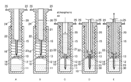
- FIGS. 1A to 1E are cross-sectional views showing an example of the configuration of a discharge-printing treatment agent storage container of the first embodiment.
- FIGS. 2A to 2D are cross-sectional views showing another example of the configuration of the discharge-printing treatment agent storage container of the first embodiment.
- FIGS. 3A to 3E are cross-sectional views showing yet another example of the configuration of the discharge-printing treatment agent storage container of the first embodiment.
- FIGS. 4A to 4E are cross-sectional views showing an example of the configuration of a discharge-printing treatment agent storage container of the second embodiment.
- FIGS. 5A to 5E are cross-sectional views showing another example of the configuration of the discharge-printing treatment agent storage container of the second embodiment.
- FIGS. 6A to 6E are cross-sectional views showing an example of the configuration of a discharge-printing treatment agent storage container of the third embodiment.
- FIG. 7 is a plan view showing an example of a stopper in the discharge-printing treatment agent storage container of the third embodiment.
- FIGS. 8A to 8E are cross-sectional views showing another example of the configuration of the discharge-printing treatment agent storage container of the third embodiment.
- FIGS. 9A to 9C are cross-sectional views showing an example of the configuration of a discharge-printing treatment agent storage container of the fourth embodiment.
- the inside of the first treatment agent-storage container is under negative pressure
- a part of the second treatment agent-storage container is opened to the outside, and the second treatment agent is capable of being transferred utilizing the negative pressure.
- the discharge-printing treatment agent storage container of the first embodiment further comprising: a downward movement unit of causing the second treatment agent-storage container to move downward, the second treatment agent-storage container is placed on the first treatment agent-storage container with a certain distance, a ceiling part of the first treatment agent-storage container is provided with the introduction port, the introduction port is sealed with the sealing member, an upper part of the second treatment agent-storage container is opened, a bottom part of the second treatment agent-storage container is provided with the discharge port, the discharge tube linked to the discharge port is a needle, and a tip of the needle is capable of being placed in the first treatment agent-storage container by causing the needle to penetrate the seal member through causing the second treatment agent-storage container to move downward by the downward movement unit.
- the inside of the first treatment agent-storage container is under an atmosphere of inactive gas
- the second treatment agent is capable of being transferred while discharging the inactive gas from the first treatment agent-storage container by applying pressure to the inside of the second treatment agent-storage container.
- the seal member sealing the introduction port of the first treatment agent-storage container is a first check valve
- a part of the first treatment agent-storage container is provided with an exhaust port for exhausting the inactive gas
- the exhaust port is sealed with a second check valve
- the second treatment agent-storage container is a cylinder capable of inserting a piston therein, a side opposite to a side of inserting the piston of the cylinder is provided with the discharge port
- the discharge tube is linked to the discharge port
- a tip of the discharge tube is capable of being placed in the first treatment agent-storage container by opening the first check valve through inserting the discharge tube to the introduction port
- the second treatment agent in the cylinder is capable of being transferred by applying pressure with the piston under a state where the tip of the discharge tube is placed in the first treatment agent-storage container
- the inactive gas is capable of being exhausted from the exhaust port by opening the second check valve according to the transfer of the second treatment agent.
- a volume of the first treatment agent-storage container is capable of being expanded by moving a part thereof, and the second treatment agent is capable of being transferred while expanding the volume of the first treatment agent-storage container by applying pressure to the inside of the second treatment agent-storage container.
- the seal member sealing the introduction port of the first treatment agent-storage container is a first check valve
- the first treatment agent-storage container has a double bottom structure including an inner bottom and an outer bottom, the inner bottom in the double bottom structure is movable toward outside, a part of the outer bottom in the double bottom structure is provided with an opening
- the second treatment agent-storage container is a cylinder capable of inserting a piston therein, a side opposite to a side of inserting the piston of the cylinder is provided with the discharge port
- the discharge tube is linked to the discharge port
- the tip of the discharge tube is capable of being placed in the first treatment agent-storage container by opening the first check valve through inserting the discharge tube to the introduction port
- the second treatment agent in the cylinder is capable of being transferred by applying pressure with the piston under a state where the tip of the discharge tube is placed in the first treatment agent-storage container, and atmospheric air is capable of being exhausted from the opening of the outer bottom according to a movement of the inner bottom by
- a part of the first treatment agent-storage container is composed of a deformable member as substitute for the inner bottom that is movable of the double bottom structure
- the second treatment agent in the cylinder is capable of being transferred by applying pressure with the piston under a state where the tip of the discharge tube is placed in the first treatment agent-storage container, and atmospheric air is capable of being exhausted from the opening of the outer bottom according to a deformation of the part of the first treatment agent-storage container by the transfer of the second treatment agent.
- a discharge-printing treatment agent storage container of the fourth embodiment further comprising: a first treatment agent-supply container, the first treatment agent-supply container is provided with a discharge port for discharging the first treatment agent, the discharge port is linked to a discharge tube, the first treatment agent-storage container is provided with a first introduction port for introducing the first treatment agent and a second introduction port for introducing the second treatment agent, the first introduction port is sealed with a first check valve, the second introduction port is sealed with a second check valve, a tip of the discharge tube on the first treatment agent-supply container is capable of being placed in the first treatment agent-storage container by opening the first check valve through inserting the discharge tube on the first treatment agent-supply container to the first introduction port, the first treatment agent is capable of being transferred from the first treatment agent-supply container to the first treatment agent-storage container by applying pressure under a state where the tip of the discharge tube on the first treatment agent-supply container is placed in the first treatment agent-storage container, a tip of the discharge tube on the second
- the discharge-printing treatment agent is prepared by mixing a first treatment agent and a second treatment agent in use.
- the first treatment agent contains a reducing treatment agent that is deteriorated by oxygen.
- the reducing treatment agent include: sulfinic acid-based reducing agents such as zinc formaldehyde sulfoxylate and sodium formaldehyde sulfoxylate; tin-based reducing agents such as stannous chloride, stannic chloride, stannous benzoate, stannous trimellitate, and stannous silicate; salts of hydrosulfite (for example, a sodium salt, an aluminum salt, and a calcium salt); a bleaching powder; sodium hypochlorite; and sodium chlorate.
- sulfinic acid-based reducing agents such as zinc formaldehyde sulfoxylate and sodium formaldehyde sulfoxylate
- tin-based reducing agents such as stannous chloride, stannic chloride, stannous benzoate,
- the first treatment agent may further contain a component besides the reducing treatment agent.
- the component besides the reducing treatment agent may be, for example, water.
- the first treatment agent is a liquid or a solid.
- the second treatment agent does not contain a component that is deteriorated by oxygen. Therefore, there is no problem even when the second treatment agent is in contact with oxygen before being mixed with the first treatment agent.
- a component of the second treatment agent may be, for example, water.
- the second treatment agent is a liquid.
- the present embodiment is an embodiment in which a second treatment agent is transferred from the second treatment agent-storage container to the first treatment agent-storage container utilizing the negative pressure in the first treatment agent-storage container.
- the discharge-printing treatment agent storage container of the present example comprises a first treatment agent-storage container 10 and a second treatment agent-storage container 20 .
- the first treatment agent-storage container 10 is cylindrical, and a ceiling part 14 thereof is provided with an introduction port 12 for introducing a second treatment agent 21 .
- the introduction port 12 is sealed with a seal member 13 , so that the inside of the first treatment agent-storage container 10 is shielded from outside air and is under negative pressure.
- gas in the first treatment agent-storage container 10 is exhausted by being vacuumed by a vacuum pump, for example, or an agent for absorbing oxygen is placed in the first treatment agent-storage container 10 .
- a first treatment agent 11 is stored in the first treatment agent-storage container 10 .
- a side wall 15 of the first treatment agent-storage container 10 is extended upward from the ceiling part 14 , and the inner side of the side wall 15 is provided with thread grooves 16 .
- the second treatment agent-storage container 20 is approximately cylindrical, the upper part thereof is opened, and the outer side of a side wall of the second treatment agent-strange container 20 is provided with screw threads 24 corresponding to the thread grooves 16 .
- An upper part on the outer side of the side wall of the second treatment agent-storage container 20 is provided with a handle 25 capable of rotating the second treatment agent-storage container 20 .
- a bottom part of the second treatment agent-storage container 20 is provided with a discharge port 22 for discharging a second treatment agent 21 .
- the discharge port 22 is linked to a discharge tube (a needle in the present embodiment) 23 .
- a method for using the discharge-printing treatment agent storage container of the present example is described below.
- a second treatment agent-storage container 20 is placed on a first treatment agent-storage container 10 with a certain distance.
- the second treatment agent-storage container 20 is screwed into a side wall 15 using a handle 25 until a needle 23 reaches in front of a seal member 13 .
- a mark indicating how far the second treatment agent-storage container 20 should be screwed into is provided on the outer side of the side wall 15 of second treatment agent-storage container 20 .
- a second treatment agent 21 is filled in the second treatment agent-storage container 20 .
- the second treatment agent-storage container 20 is screwed into the side wall 15 using the handle 25 until the bottom surface thereof is in contact with the seal member 13 .
- the needle 23 penetrates the seal member 13 , and the tip of the needle 23 is placed in the first treatment agent-storage container 10 .
- the inside of the first treatment agent-storage container 10 is under negative pressure, so that the second treatment agent 21 is transferred from the second treatment agent-storage container 20 to the first treatment agent-storage container 10 by atmospheric pressure.
- a small amount of the second treatment agent 21 remains in the second treatment agent-storage container 20 , so that a discharge-printing treatment agent 30 prepared by mixing a first treatment agent 11 and the second treatment agent 21 is shielded from outside air.
- a cylindrical transport tube 31 for a discharge-printing treatment agent is inserted into the second treatment agent-storage container 20 .
- the opening of the bottom part of the transport tube 31 is brought into contact with the discharge port 22 . Thereafter, the discharge-printing treatment agent 30 is transported to the outside using the transport tube 31 .
- the discharge-printing of fabric such as a T-shirt may be performed by applying the discharge-printing treatment agent 30 by an ink-jet method, a spraying method, a stamping method, a brushing method, or a rolling method.
- the discharge-printing of fabric the same may apply to the other examples of the present embodiment and the other embodiments.
- FIGS. 2A to 2D Another example of the configuration of the discharge-printing treatment agent storage container of the present embodiment is shown in cross-sectional views of FIGS. 2A to 2D .
- the identical parts to those in FIGS. 1A to 1E are indicated by identical reference numerals.
- the configuration of the discharge-printing treatment agent storage container of the present example is the same as that shown in FIGS. 1A to 1E except that a second treatment agent 21 is previously filled in a second treatment agent-storage container 20 , and an upper opening of the second treatment agent-storage container 20 is sealed with a seal member 26 .
- a method for using the discharge-printing treatment agent storage container of the present example is described below. First, as shown in FIG. 2A , a second treatment agent-storage container 20 is placed on a first treatment agent-storage container 10 so that a needle 23 is in front of a seal member 13 .
- the second treatment agent-storage container 20 is screwed into a side wall 15 using a handle 25 until the bottom surface thereof is in contact with the seal member 13 .
- the needle 23 penetrates the seal member 13 , and the tip of the needle 23 is placed in the first treatment agent-storage container 10 .
- a seal member 26 with which an upper opening of the second treatment agent-storage container 20 has been sealed is removed.
- the inside of the first treatment agent-storage container 10 is under negative pressure. Therefore, a second treatment agent 21 is transferred from the second treatment agent-storage container 20 to the first treatment agent-storage container 10 .
- FIGS. 2C and 2D the same operations as shown in FIGS. 1D and 1E are performed.
- FIGS. 3A to 3E Yet another example of the configuration of the discharge-printing treatment agent storage container of the present embodiment is shown in cross-sectional views of FIGS. 3A to 3E .
- identical parts to those in FIGS. 1A to 1E are indicated by the identical reference numerals.
- the present example is an example in which a second treatment agent is transferred from a second treatment agent-storage container to a first treatment agent-storage container by applying pressure with a transport tube besides negative pressure in the first treatment agent-storage container.
- a diameter of an upper opening of a second treatment agent-storage container 20 is increased at its upper end part in order for a transport tube 31 to be easily inserted therein.
- the discharge-printing treatment agent storage container of the present example is provided with a receiving groove 27 for receiving an overflow of a second treatment agent 21 from the upper end part of the upper opening of the second treatment agent-storage container 20 when the transport tube 31 is inserted.
- FIG. 3A A method for using the discharge-printing treatment agent storage container of the present example is described below.
- a second treatment agent-storage container 20 is screwed into a side wall 15 using a handle 25 until a needle 23 reaches in front of a seal member 13 in the same manner as in FIG. 1A .
- a second treatment agent 21 is filled in the second treatment agent-storage container 20 up to the upper end part of the upper opening.
- the second treatment agent storage container 20 is screwed into the side wall 15 using the handle 25 until the bottom surface thereof is in contact with the seal member 13 , so that the needle 23 penetrates the seal member 13 , and the tip of the needle 23 is placed in the first treatment agent-storage container 10 .
- a transport tube 31 is placed so as to be in contact with the upper surface of the second treatment agent 21 .
- the second treatment agent 21 is transferred from the second treatment agent-storage container 20 to the first treatment agent-storage container 10 by applying pressure with the transport tube 31 besides negative pressure in the first treatment agent-storage container 10 .
- the second treatment agent 21 may be transferred in a short time.
- an overflow of the second treatment agent 21 from an upper end part of an upper opening of the second treatment agent-storage container 20 is received by a receiving groove 27 , so that there is no case that a surrounding area of the discharge-printing treatment agent storage container gets dirty with the second treatment agent 21 .
- the present embodiment is an embodiment in which a second treatment agent is transferred from a syringe that is a second treatment agent-storage container to a first treatment agent-storage container with a piston.
- the discharge-printing treatment agent storage container of the present example comprises a first treatment agent-storage container 40 and a cylinder (second treatment agent-storage container) 50 capable of inserting a piston 54 therein.
- the first treatment agent-storage container 40 has a tubular shape such as a cylindrical shape or a rectangular-tube like shape.
- a ceiling part 44 of the first treatment agent-storage container 40 is provided with an introduction port 42 for introducing a second treatment agent 51 .
- the introduction port 42 is sealed with a first check valve 43 , so that the inside of the first treatment agent-storage container 40 is shielded from outside air and is under an atmosphere of inactive gas.
- the inactive gas include nitrogen and argon.
- An upper part of a side wall of the first treatment agent-storage container 40 is provided with an exhaust port 45 for exhausting the inactive gas.
- the exhaust port 45 is sealed with a second check valve 46 .
- a first treatment agent 41 is stored in the first treatment agent-storage container 40 .
- the cylinder 50 has a tubular shape such as a cylindrical shape or a rectangular-tube like shape.
- the side opposite to the side of inserting the piston 54 (upper side in FIGS. 4A to 4E ) of the cylinder 50 is provided with a discharge port 52 .
- the discharge port 52 is linked to a discharge tube 53 .
- a method for using the discharge-printing treatment agent storage container of the present example is described below. First, as shown in FIG. 4A , a second treatment agent 51 is drawn into a syringe 50 .
- the tip of a discharge tube 53 is placed in a first treatment agent-storage container 40 by opening a first check valve 43 through inserting a discharge tube 53 into an introduction port 42 .
- the second treatment agent 51 in the sylinder 50 is transferred to the first treatment agent-storage container 40 by applying pressure to the second treatment agent 51 with a piston 54 under the state where the tip of the discharge tube 53 is placed in the first treatment agent-storage container 40 .
- inactive gas is exhausted from an exhaust port 45 by opening a second check valve 46 according to the transfer of the second treatment agent 51 .
- a transport needle 62 that is placed at the tip of a transport tube 61 is inserted into the introduction port 42 , so that the first check valve 43 is opened. Then, under this state, the discharge-printing treatment agent 60 is transported to the outside.
- FIGS. 5A to 5E Another example of the configuration of the discharge-printing treatment agent storage container of the present embodiment is shown in cross-sectional views of FIGS. 5A to 5E .
- identical parts to those in FIGS. 4A to 4E are indicated by the identical reference numerals.
- the present example is an example in which a first treatment agent-storage container is provided with an introduction path for a discharge tube.
- the discharge-printing treatment agent storage container of the present example comprises a first treatment agent-storage container 40 and a cylinder (second treatment agent-storage container) 50 capable of inserting a piston 54 therein.
- the first treatment agent-storage container 40 has a tubular shape such as a cylindrical shape or a rectangular-tube like shape.
- a bottom part 47 of the first treatment agent-storage container 40 is provided with an introduction port 42 for introducing a second treatment agent 51 .
- the first treatment agent-storage container 40 is provided with a first treatment agent storage part 48 .
- the side part of the first treatment agent storage part 48 is provided with an introduction path 49 extended from the introduction port 42 toward the inside of the first treatment agent-storage container 40 .
- the boundary between the first treatment agent storage part 48 and the introduction path 49 is sealed with a first check valve 43 , so that the inside of the first treatment agent-storage container 40 is shielded from outside air and is under an atmosphere of inactive gas.
- the inactive gas is the same as mentioned above.
- a ceiling part of the first treatment agent-storage container 40 is provided with an exhaust port 45 for exhausting the inactive gas.
- the exhaust port 45 is sealed with a second check valve 46 .
- a first treatment agent 41 is stored in the first treatment agent storage part 48 .
- the configuration of the cylinder 50 is the same as that in the discharge-printing treatment agent storage container shown in FIGS. 4A to 4E .
- a method for using the discharge-printing treatment agent storage container of the present example is described below. First, as shown in FIG. 5A , a second treatment agent 51 is drawn into a cylinder 50 .
- the tip of a discharge tube 53 is placed in front of a first check valve 43 by inserting the tip of the discharge tube 53 from an introduction port 42 to an introduction path 49 .
- the second treatment agent 51 is transferred to a first treatment agent-storage container 10 by opening the first check valve 43 through applying pressure to the second treatment agent 51 that is in the cylinder 50 with a piston 54 under the satate where the tip of the discharge tube 53 is placed in front of the first check valve 43 .
- inactive gas is exhausted from an exhaust port 45 by opening a second check valve 46 according to the transfer of the second treatment agent 51 .
- a transport needle 62 that is placed at the tip of a transport tube 61 is caused to penetrate the second check valve 46 , so that the tip of the transport needle 62 is inserted into the first treatment agent storage part 48 . Thereafter, the discharge-printing treatment agent 60 is transported to the outside.
- the present embodiment is an embodiment in which a second treatment agent is transferred while expanding a volume of a first treatment agent-storage container by causing a part thereof to move by applying pressure to the inside of a second treatment agent-storage container.
- the discharge-printing treatment agent storage container of the present example comprises a first treatment agent-storage container 40 and a cylinder (second treatment agent-storage container) 50 capable of inserting a piston 54 therein.
- the first treatment agent-storage container 40 has a tubular shape such as a cylindrical shape or a rectangular-tube like shape.
- a ceiling part 44 of the first treatment agent-storage container 40 is provided with an introduction port 42 for introducing a second treatment agent 51 .
- the introduction port 42 is sealed with a first check valve 43 .
- the first treatment agent-storage container 40 is filled with a first treatment agent 41 and is shielded from outside air.
- the first treatment agent-storage container 40 has a double bottom structure including an inner bottom 71 and an outer bottom 72 . In the double bottom structure, the inner bottom 71 is movable toward the outside, and the outer bottom 72 is provided with an opening 73 .
- the configuration of the cylinder 50 is the same as that in the discharge-printing treatment agent storage container shown in FIGS. 4A to 4E except that the cylinder 50 includes a plan stopper 55 that has a plan shape shown in FIG.
- the state where the second treatment agent 51 is stored in the syringe 50 is maintained for a long period of time by fixing the end part of the piston 54 with the stopper 55 .
- a method for using the discharge-printing treatment agent storage container of the present example is described below.
- a second treatment agent 51 is drawn into a cylinder 50 .
- the end part of a piston 54 is fixed with a stopper 55 , so that the state where the second treatment agent 51 is stored in the cylinder 50 is maintained.
- the tip of a discharge tube 53 is placed in a first treatment agent-storage container 40 by opening a first check valve 43 through inserting the discharge tube 53 into an introduction port 42 .
- the second treatment agent 51 in the cylinder 50 is transferred to the first treatment agent-storage container 40 by applying pressure to the second treatment agent 51 with the piston 54 under the state where the tip of the discharge tube 53 is placed in the first treatment agent-storage container 40 .
- air is discharged from an opening 73 of an outer bottom 72 according to the movement of an inner bottom 71 caused by the transfer of the second treatment agent 51 .
- FIGS. 6D and 6E the same operations as shown in FIGS. 4D and 4E are performed.
- FIGS. 8A to 8E Another example of the configuration of the discharge-printing treatment agent storage container of the present embodiment is shown in cross-sectional views of FIGS. 8A to 8E .
- FIGS. 8A to 8E identical parts to those in FIGS. 6A to 6E are indicated by the identical reference numerals.
- the configuration of the discharge-printing treatment agent storage container of the present example is the same as that shown in FIGS. 6A to 6E except that an inner bottom 71 is the one formed of a deformable member as substitute for the one that is movable.
- a second treatment agent 51 may be transferred by deforming the deformable member (for example, a polypropylene sheet, a polyethylene sheet, or a silicone resin sheet) through applying pressure.
- the deformable member for example, a polypropylene sheet, a polyethylene sheet, or a silicone resin sheet
- the discharge-printing treatment agent storage container of the second embodiment may comprise a stopper 55 as in the present embodiment.
- the present embodiment is an embodiment further comprising a first treatment agent-supply container.
- the discharge-printing treatment agent storage container of the present embodiment comprises a first treatment agent-storage container 80 , a second treatment agent-storage container 100 , and a first treatment agent-supply container 110 .
- the first treatment agent-storage container 80 has a tubular shape such as a cylindrical shape or a rectangular-tube like shape.
- a ceiling part 85 of the first treatment agent-storage container 80 is provided with a first introduction port 81 for introducing a first treatment agent 111 and a second introduction port 82 for introducing a second treatment agent 101 .
- the first introduction port 81 is sealed with a first check valve 83
- the second introduction port 82 is sealed with a second check valve 84 , so that the inside of the first treatment agent-storage container 80 is shielded from outside air and is under negative pressure.
- a method for causing the inside of the first treatment agent-storage container 80 to he under negative pressure is as mentioned above.
- the first treatment agent-storage container 80 is provided with needles 87 and 88 at the respective positions on the bottom part 86 , corresponding to the second introduction port 81 and the first introduction port 82 of the ceiling part 85 .
- a side wall of the first treatment agent-storage container 80 is provided with a discharge port 89 for transporting a prepared discharge-printing treatment agent 120 to the outside.
- the discharge port 89 is sealed with a seal member 90 .
- the second treatment agent-storage container 100 has a tubular shape such as a cylindrical shape or a rectangular-tube like shape, and the upper part thereof is opened. A bottom part thereof is provided with a discharge port 102 for discharging the second treatment agent 101 .
- the discharge port 102 is linked to a discharge tube 103 .
- a bottom part of the discharge tube 103 is sealed with a seal member 104 .
- the first treatment agent-supply container 110 has a tubular shape such as a cylindrical shape or a rectangular-tube like shape. The bottom part of the first treatment agent-supply container 110 is provided with a discharge port 112 for discharging the first treatment agent 111 .
- the discharge port 112 is linked to a discharge tube 113 .
- the bottom part of the discharge tube 113 is sealed with a seal member 114 , so that the inside of the first treatment agent-supply container 110 is shielded from outside air and is under an atmosphere of inactive gas.
- the inactive gas is the same as mentioned above.
- a method for using the discharge-printing treatment agent storage container of the present embodiment is described below.
- the tips of discharge tubes 103 and 113 are placed in a first treatment agent-storage container 80 by opening a second check valve 84 and a first check valve 83 through inserting the discharge tubes 103 and 113 into a second introduction port 82 and a first introduction port 81 , respectively.
- a needle 88 penetrates a seal member 104
- a needle 87 penetrates a seal member 114 . Therefore, since the inside of the first treatment agent-storage container 80 is under negative pressure, a second treatment agent 101 is transferred to the first treatment agent-storage container 80 by atmosphere pressure, and a first treatment agent 111 is transferred to the same by pressure of the inactive gas.
- a transport needle 122 placed at the tip of a transport tube 121 is caused to penetrate a seal member 90 , so that the tip of the transport needle 122 is inserted into the first treatment agent-storage container 80 . Thereafter, a discharge-printing treatment agent 120 is transported to the outside.
Landscapes
- Package Specialized In Special Use (AREA)
- Packages (AREA)
- Coating Apparatus (AREA)
Abstract
Description
- This application claims priority from Japanese Patent Application No. 2011-076276 filed on Mar. 30, 2011. The entire subject matter of the Japanese Patent Application is incorporated herein by reference.
- There are cases that designs are printed on T-shirts, bathing suits, and the like by an ink-jet method in production of T-shirts, bathing suits, and the like having original designs. In the case where a ground color of a T-shirt or the like is white, a printing may be performed without a pretreatment. In contrast, in the case where the ground color is deep such as black, it is necessary that a design is printed after a discharge-printing treatment. For the discharge-printing treatment, a dedicated discharge-printing treatment agent is used. Many of discharge-printing treatment agents are two-pack type discharge-printing treatment agents each composed of two types of treatment agents. In the two-pack type discharge-printing treatment agent, one of the two types of treatment agents is a reducing treatment agent. Therefore, each of the two types of treatment agents is stored in a different container, and in use, a discharge-printing treatment agent is prepared by mixing the two-types of them.
- A discharge-printing treatment agent storage container is a discharge-printing treatment agent storage container for storing a discharge-printing treatment agent, the discharge-printing treatment agent storage container comprising: a first treatment agent-storage container; and a second treatment agent-storage container, wherein the discharge printing treatment agent is prepared by mixing a first treatment agent and a second treatment agent in use, the first treatment agent contains a reducing treatment agent, a part of the first treatment agent-storage container is provided with an introduction port for introducing the second treatment agent, the inside of the first treatment agent-storage container is shielded from outside air by sealing the introduction port with a seal member, the second treatment agent-storage container is provided with a discharge port for discharging the second treatment agent, the discharge port is linked to a discharge tube, a tip of the discharge tube is capable of being placed in the first treatment agent-storage container by releasing the introduction port from being sealed with the seal member, and the second treatment agent is capable of being transferred from the second treatment agent-storage container to the first treatment agent-storage container by pressure under a state where the tip of the discharge tube is placed in the first treatment agent-storage container.
-
FIGS. 1A to 1E are cross-sectional views showing an example of the configuration of a discharge-printing treatment agent storage container of the first embodiment. -
FIGS. 2A to 2D are cross-sectional views showing another example of the configuration of the discharge-printing treatment agent storage container of the first embodiment. -
FIGS. 3A to 3E are cross-sectional views showing yet another example of the configuration of the discharge-printing treatment agent storage container of the first embodiment. -
FIGS. 4A to 4E are cross-sectional views showing an example of the configuration of a discharge-printing treatment agent storage container of the second embodiment. -
FIGS. 5A to 5E are cross-sectional views showing another example of the configuration of the discharge-printing treatment agent storage container of the second embodiment. -
FIGS. 6A to 6E are cross-sectional views showing an example of the configuration of a discharge-printing treatment agent storage container of the third embodiment. -
FIG. 7 is a plan view showing an example of a stopper in the discharge-printing treatment agent storage container of the third embodiment. -
FIGS. 8A to 8E are cross-sectional views showing another example of the configuration of the discharge-printing treatment agent storage container of the third embodiment. -
FIGS. 9A to 9C are cross-sectional views showing an example of the configuration of a discharge-printing treatment agent storage container of the fourth embodiment. - In a discharge-printing treatment agent storage container of the first embodiment, the inside of the first treatment agent-storage container is under negative pressure, a part of the second treatment agent-storage container is opened to the outside, and the second treatment agent is capable of being transferred utilizing the negative pressure.
- The discharge-printing treatment agent storage container of the first embodiment, further comprising: a downward movement unit of causing the second treatment agent-storage container to move downward, the second treatment agent-storage container is placed on the first treatment agent-storage container with a certain distance, a ceiling part of the first treatment agent-storage container is provided with the introduction port, the introduction port is sealed with the sealing member, an upper part of the second treatment agent-storage container is opened, a bottom part of the second treatment agent-storage container is provided with the discharge port, the discharge tube linked to the discharge port is a needle, and a tip of the needle is capable of being placed in the first treatment agent-storage container by causing the needle to penetrate the seal member through causing the second treatment agent-storage container to move downward by the downward movement unit.
- In a discharge-printing treatment agent storage container of the second embodiment, the inside of the first treatment agent-storage container is under an atmosphere of inactive gas, and the second treatment agent is capable of being transferred while discharging the inactive gas from the first treatment agent-storage container by applying pressure to the inside of the second treatment agent-storage container.
- In the discharge-printing treatment agent storage container of the second embodiment, the seal member sealing the introduction port of the first treatment agent-storage container is a first check valve, a part of the first treatment agent-storage container is provided with an exhaust port for exhausting the inactive gas, the exhaust port is sealed with a second check valve, the second treatment agent-storage container is a cylinder capable of inserting a piston therein, a side opposite to a side of inserting the piston of the cylinder is provided with the discharge port, the discharge tube is linked to the discharge port, a tip of the discharge tube is capable of being placed in the first treatment agent-storage container by opening the first check valve through inserting the discharge tube to the introduction port, the second treatment agent in the cylinder is capable of being transferred by applying pressure with the piston under a state where the tip of the discharge tube is placed in the first treatment agent-storage container, and the inactive gas is capable of being exhausted from the exhaust port by opening the second check valve according to the transfer of the second treatment agent.
- In a discharge-printing treatment agent storage container of the third embodiment, a volume of the first treatment agent-storage container is capable of being expanded by moving a part thereof, and the second treatment agent is capable of being transferred while expanding the volume of the first treatment agent-storage container by applying pressure to the inside of the second treatment agent-storage container.
- In the discharge-printing treatment agent storage container of the third embodiment, the seal member sealing the introduction port of the first treatment agent-storage container is a first check valve, the first treatment agent-storage container has a double bottom structure including an inner bottom and an outer bottom, the inner bottom in the double bottom structure is movable toward outside, a part of the outer bottom in the double bottom structure is provided with an opening, the second treatment agent-storage container is a cylinder capable of inserting a piston therein, a side opposite to a side of inserting the piston of the cylinder is provided with the discharge port, the discharge tube is linked to the discharge port, the tip of the discharge tube is capable of being placed in the first treatment agent-storage container by opening the first check valve through inserting the discharge tube to the introduction port, the second treatment agent in the cylinder is capable of being transferred by applying pressure with the piston under a state where the tip of the discharge tube is placed in the first treatment agent-storage container, and atmospheric air is capable of being exhausted from the opening of the outer bottom according to a movement of the inner bottom by the transfer of the second treatment agent.
- In the discharge-printing treatment agent storage container of the third embodiment, a part of the first treatment agent-storage container is composed of a deformable member as substitute for the inner bottom that is movable of the double bottom structure, the second treatment agent in the cylinder is capable of being transferred by applying pressure with the piston under a state where the tip of the discharge tube is placed in the first treatment agent-storage container, and atmospheric air is capable of being exhausted from the opening of the outer bottom according to a deformation of the part of the first treatment agent-storage container by the transfer of the second treatment agent.
- A discharge-printing treatment agent storage container of the fourth embodiment, further comprising: a first treatment agent-supply container, the first treatment agent-supply container is provided with a discharge port for discharging the first treatment agent, the discharge port is linked to a discharge tube, the first treatment agent-storage container is provided with a first introduction port for introducing the first treatment agent and a second introduction port for introducing the second treatment agent, the first introduction port is sealed with a first check valve, the second introduction port is sealed with a second check valve, a tip of the discharge tube on the first treatment agent-supply container is capable of being placed in the first treatment agent-storage container by opening the first check valve through inserting the discharge tube on the first treatment agent-supply container to the first introduction port, the first treatment agent is capable of being transferred from the first treatment agent-supply container to the first treatment agent-storage container by applying pressure under a state where the tip of the discharge tube on the first treatment agent-supply container is placed in the first treatment agent-storage container, a tip of the discharge tube on the second treatment agent-storage container is capable of being placed in the first treatment agent-storage container by opening the second check valve through inserting the discharge tube on the second treatment agent-storage container to the second introduction port, and the second treatment agent is capable of being transferred from the second treatment agent-storage container to the first treatment agent-storage container by pressure under a state where the tip of the discharge tube on the second treatment agent-storage container is placed in the first treatment agent-storage container.
- The discharge-printing treatment agent is prepared by mixing a first treatment agent and a second treatment agent in use. The first treatment agent contains a reducing treatment agent that is deteriorated by oxygen. Examples of the reducing treatment agent include: sulfinic acid-based reducing agents such as zinc formaldehyde sulfoxylate and sodium formaldehyde sulfoxylate; tin-based reducing agents such as stannous chloride, stannic chloride, stannous benzoate, stannous trimellitate, and stannous silicate; salts of hydrosulfite (for example, a sodium salt, an aluminum salt, and a calcium salt); a bleaching powder; sodium hypochlorite; and sodium chlorate. The first treatment agent may further contain a component besides the reducing treatment agent. The component besides the reducing treatment agent may be, for example, water. The first treatment agent is a liquid or a solid. On the other hand, the second treatment agent does not contain a component that is deteriorated by oxygen. Therefore, there is no problem even when the second treatment agent is in contact with oxygen before being mixed with the first treatment agent. A component of the second treatment agent may be, for example, water. The second treatment agent is a liquid.
- The embodiments as examples of the present invention are described below with reference to the views. Note here that the present invention is not restricted or limited by the following embodiments.
- The present embodiment is an embodiment in which a second treatment agent is transferred from the second treatment agent-storage container to the first treatment agent-storage container utilizing the negative pressure in the first treatment agent-storage container.
- An example of the configuration of the discharge-printing treatment agent storage container of the present embodiment is shown in cross-sectional views of
FIGS. 1A to 1E . As shown inFIGS. 1A to 1E , the discharge-printing treatment agent storage container of the present example comprises a first treatment agent-storage container 10 and a second treatment agent-storage container 20. The first treatment agent-storage container 10 is cylindrical, and aceiling part 14 thereof is provided with anintroduction port 12 for introducing asecond treatment agent 21. Theintroduction port 12 is sealed with aseal member 13, so that the inside of the first treatment agent-storage container 10 is shielded from outside air and is under negative pressure. In order to make the inside of the first treatment agent-storage container 10 under negative pressure, gas in the first treatment agent-storage container 10 is exhausted by being vacuumed by a vacuum pump, for example, or an agent for absorbing oxygen is placed in the first treatment agent-storage container 10. Afirst treatment agent 11 is stored in the first treatment agent-storage container 10. Aside wall 15 of the first treatment agent-storage container 10 is extended upward from theceiling part 14, and the inner side of theside wall 15 is provided withthread grooves 16. The second treatment agent-storage container 20 is approximately cylindrical, the upper part thereof is opened, and the outer side of a side wall of the second treatment agent-strange container 20 is provided withscrew threads 24 corresponding to thethread grooves 16. An upper part on the outer side of the side wall of the second treatment agent-storage container 20 is provided with ahandle 25 capable of rotating the second treatment agent-storage container 20. A bottom part of the second treatment agent-storage container 20 is provided with adischarge port 22 for discharging asecond treatment agent 21. Thedischarge port 22 is linked to a discharge tube (a needle in the present embodiment) 23. - A method for using the discharge-printing treatment agent storage container of the present example is described below. First, as shown in
FIG. 1A , a second treatment agent-storage container 20 is placed on a first treatment agent-storage container 10 with a certain distance. Specifically, the second treatment agent-storage container 20 is screwed into aside wall 15 using ahandle 25 until aneedle 23 reaches in front of aseal member 13. In the discharge-printing treatment agent storage container of the present example, a mark indicating how far the second treatment agent-storage container 20 should be screwed into is provided on the outer side of theside wall 15 of second treatment agent-storage container 20. - Then, as shown in
FIG. 1B , asecond treatment agent 21 is filled in the second treatment agent-storage container 20. - Thereafter, as shown in
FIG. 1C , the second treatment agent-storage container 20 is screwed into theside wall 15 using thehandle 25 until the bottom surface thereof is in contact with theseal member 13. Thus, theneedle 23 penetrates theseal member 13, and the tip of theneedle 23 is placed in the first treatment agent-storage container 10. In this case, the inside of the first treatment agent-storage container 10 is under negative pressure, so that thesecond treatment agent 21 is transferred from the second treatment agent-storage container 20 to the first treatment agent-storage container 10 by atmospheric pressure. In this case, as shown inFIG. 1D , a small amount of thesecond treatment agent 21 remains in the second treatment agent-storage container 20, so that a discharge-printing treatment agent 30 prepared by mixing afirst treatment agent 11 and thesecond treatment agent 21 is shielded from outside air. - After completion of the transfer of the
second treatment agent 21, as shown inFIG. 1D , acylindrical transport tube 31 for a discharge-printing treatment agent, the bottom part of which has been opened, is inserted into the second treatment agent-storage container 20. - After discharging the small amount of the
second treatment agent 21 remaining in the second treatmentagent storage container 20, as shown inFIG. 1E , the opening of the bottom part of thetransport tube 31 is brought into contact with thedischarge port 22. Thereafter, the discharge-printing treatment agent 30 is transported to the outside using thetransport tube 31. - In the present example, the discharge-printing of fabric such as a T-shirt may be performed by applying the discharge-
printing treatment agent 30 by an ink-jet method, a spraying method, a stamping method, a brushing method, or a rolling method. With respect to the discharge-printing of fabric, the same may apply to the other examples of the present embodiment and the other embodiments. - Another example of the configuration of the discharge-printing treatment agent storage container of the present embodiment is shown in cross-sectional views of
FIGS. 2A to 2D . InFIGS. 2A to 2D , the identical parts to those inFIGS. 1A to 1E are indicated by identical reference numerals. As shown inFIGS. 2A to 2D , the configuration of the discharge-printing treatment agent storage container of the present example is the same as that shown inFIGS. 1A to 1E except that asecond treatment agent 21 is previously filled in a second treatment agent-storage container 20, and an upper opening of the second treatment agent-storage container 20 is sealed with aseal member 26. - A method for using the discharge-printing treatment agent storage container of the present example is described below. First, as shown in
FIG. 2A , a second treatment agent-storage container 20 is placed on a first treatment agent-storage container 10 so that aneedle 23 is in front of aseal member 13. - Then, as shown in
FIG. 2B , the second treatment agent-storage container 20 is screwed into aside wall 15 using ahandle 25 until the bottom surface thereof is in contact with theseal member 13. Thus, theneedle 23 penetrates theseal member 13, and the tip of theneedle 23 is placed in the first treatment agent-storage container 10. Thereafter, aseal member 26 with which an upper opening of the second treatment agent-storage container 20 has been sealed is removed. In this case, the inside of the first treatment agent-storage container 10 is under negative pressure. Therefore, asecond treatment agent 21 is transferred from the second treatment agent-storage container 20 to the first treatment agent-storage container 10. - Subsequently, as shown in
FIGS. 2C and 2D , the same operations as shown inFIGS. 1D and 1E are performed. - Yet another example of the configuration of the discharge-printing treatment agent storage container of the present embodiment is shown in cross-sectional views of
FIGS. 3A to 3E . InFIGS. 3A to 3E , identical parts to those inFIGS. 1A to 1E are indicated by the identical reference numerals. The present example is an example in which a second treatment agent is transferred from a second treatment agent-storage container to a first treatment agent-storage container by applying pressure with a transport tube besides negative pressure in the first treatment agent-storage container. As shown inFIGS. 3A to 3E , in the discharge-printing treatment agent storage container of the present example, a diameter of an upper opening of a second treatment agent-storage container 20 is increased at its upper end part in order for atransport tube 31 to be easily inserted therein. Moreover, the discharge-printing treatment agent storage container of the present example is provided with a receivinggroove 27 for receiving an overflow of asecond treatment agent 21 from the upper end part of the upper opening of the second treatment agent-storage container 20 when thetransport tube 31 is inserted. - A method for using the discharge-printing treatment agent storage container of the present example is described below. First, as shown in
FIG. 3A , a second treatment agent-storage container 20 is screwed into aside wall 15 using ahandle 25 until aneedle 23 reaches in front of aseal member 13 in the same manner as inFIG. 1A . - Then, as shown in
FIG. 3B , asecond treatment agent 21 is filled in the second treatment agent-storage container 20 up to the upper end part of the upper opening. - Thereafter, as shown in
FIG. 3C , the second treatmentagent storage container 20 is screwed into theside wall 15 using thehandle 25 until the bottom surface thereof is in contact with theseal member 13, so that theneedle 23 penetrates theseal member 13, and the tip of theneedle 23 is placed in the first treatment agent-storage container 10. Subsequently, atransport tube 31 is placed so as to be in contact with the upper surface of thesecond treatment agent 21. - Then, as shown in
FIG. 3D , thesecond treatment agent 21 is transferred from the second treatment agent-storage container 20 to the first treatment agent-storage container 10 by applying pressure with thetransport tube 31 besides negative pressure in the first treatment agent-storage container 10. According to the present example, thesecond treatment agent 21 may be transferred in a short time. Moreover, an overflow of thesecond treatment agent 21 from an upper end part of an upper opening of the second treatment agent-storage container 20 is received by a receivinggroove 27, so that there is no case that a surrounding area of the discharge-printing treatment agent storage container gets dirty with thesecond treatment agent 21. - Subsequently, as shown in
FIG. 3E , the same operation as shown inFIG. 1E is performed. - The present embodiment is an embodiment in which a second treatment agent is transferred from a syringe that is a second treatment agent-storage container to a first treatment agent-storage container with a piston.
- An example of the configuration of the discharge-printing treatment agent storage container of the present embodiment is shown in cross-sectional views of
FIGS. 4A to 4E . As shown inFIGS. 4A to 4E , the discharge-printing treatment agent storage container of the present example comprises a first treatment agent-storage container 40 and a cylinder (second treatment agent-storage container) 50 capable of inserting apiston 54 therein. The first treatment agent-storage container 40 has a tubular shape such as a cylindrical shape or a rectangular-tube like shape. Aceiling part 44 of the first treatment agent-storage container 40 is provided with anintroduction port 42 for introducing asecond treatment agent 51. Theintroduction port 42 is sealed with afirst check valve 43, so that the inside of the first treatment agent-storage container 40 is shielded from outside air and is under an atmosphere of inactive gas. Examples of the inactive gas include nitrogen and argon. An upper part of a side wall of the first treatment agent-storage container 40 is provided with anexhaust port 45 for exhausting the inactive gas. Theexhaust port 45 is sealed with asecond check valve 46. Afirst treatment agent 41 is stored in the first treatment agent-storage container 40. Thecylinder 50 has a tubular shape such as a cylindrical shape or a rectangular-tube like shape. The side opposite to the side of inserting the piston 54 (upper side inFIGS. 4A to 4E ) of thecylinder 50 is provided with adischarge port 52. Thedischarge port 52 is linked to adischarge tube 53. - A method for using the discharge-printing treatment agent storage container of the present example is described below. First, as shown in
FIG. 4A , asecond treatment agent 51 is drawn into asyringe 50. - Then, as shown in
FIG. 4B , the tip of adischarge tube 53 is placed in a first treatment agent-storage container 40 by opening afirst check valve 43 through inserting adischarge tube 53 into anintroduction port 42. - Thereafter, as shown in
FIG. 4C , thesecond treatment agent 51 in thesylinder 50 is transferred to the first treatment agent-storage container 40 by applying pressure to thesecond treatment agent 51 with apiston 54 under the state where the tip of thedischarge tube 53 is placed in the first treatment agent-storage container 40. In this case, inactive gas is exhausted from anexhaust port 45 by opening asecond check valve 46 according to the transfer of thesecond treatment agent 51. - Then, as shown in
FIG. 4D , by pulling the tip of thedischarge tube 53 out of theintroduction port 42, theintroduction port 42 is sealed with thefirst check valve 43, and theexhaust port 45 is sealed with thesecond check valve 46. Therefore, a discharge-printing treatment agent 60 prepared by mixing afirst treatment agent 41 and thesecond treatment agent 51 is shielded from outside air. - Subsequently, as shown in
FIG. 4E , atransport needle 62 that is placed at the tip of atransport tube 61 is inserted into theintroduction port 42, so that thefirst check valve 43 is opened. Then, under this state, the discharge-printing treatment agent 60 is transported to the outside. - Another example of the configuration of the discharge-printing treatment agent storage container of the present embodiment is shown in cross-sectional views of
FIGS. 5A to 5E . InFIGS. 5A to 5E , identical parts to those inFIGS. 4A to 4E are indicated by the identical reference numerals. The present example is an example in which a first treatment agent-storage container is provided with an introduction path for a discharge tube. As shown inFIGS. 5A to 5E , the discharge-printing treatment agent storage container of the present example comprises a first treatment agent-storage container 40 and a cylinder (second treatment agent-storage container) 50 capable of inserting apiston 54 therein. The first treatment agent-storage container 40 has a tubular shape such as a cylindrical shape or a rectangular-tube like shape. Abottom part 47 of the first treatment agent-storage container 40 is provided with anintroduction port 42 for introducing asecond treatment agent 51. The first treatment agent-storage container 40 is provided with a first treatmentagent storage part 48. The side part of the first treatmentagent storage part 48 is provided with anintroduction path 49 extended from theintroduction port 42 toward the inside of the first treatment agent-storage container 40. The boundary between the first treatmentagent storage part 48 and theintroduction path 49 is sealed with afirst check valve 43, so that the inside of the first treatment agent-storage container 40 is shielded from outside air and is under an atmosphere of inactive gas. The inactive gas is the same as mentioned above. A ceiling part of the first treatment agent-storage container 40 is provided with anexhaust port 45 for exhausting the inactive gas. Theexhaust port 45 is sealed with asecond check valve 46. Afirst treatment agent 41 is stored in the first treatmentagent storage part 48. The configuration of thecylinder 50 is the same as that in the discharge-printing treatment agent storage container shown inFIGS. 4A to 4E . - A method for using the discharge-printing treatment agent storage container of the present example is described below. First, as shown in
FIG. 5A , asecond treatment agent 51 is drawn into acylinder 50. - Then, as shown in
FIG. 5B , the tip of adischarge tube 53 is placed in front of afirst check valve 43 by inserting the tip of thedischarge tube 53 from anintroduction port 42 to anintroduction path 49. - Thereafter, as shown in
FIG. 5C , thesecond treatment agent 51 is transferred to a first treatment agent-storage container 10 by opening thefirst check valve 43 through applying pressure to thesecond treatment agent 51 that is in thecylinder 50 with apiston 54 under the satate where the tip of thedischarge tube 53 is placed in front of thefirst check valve 43. In this case, inactive gas is exhausted from anexhaust port 45 by opening asecond check valve 46 according to the transfer of thesecond treatment agent 51. - Subsequently, as shown in
FIG. 5D , by pulling the tip of thedischarge tube 53 out of theintroduction path 49 and theintroduction port 42, the boundary between a first treatmentagent storage part 48 and theintroduction path 49 is sealed with thefirst check valve 43, and theexhaust port 45 is sealed with thesecond check valve 46. Therefore, a discharge-printing treatment agent 60 prepared by mixing afirst treatment agent 41 and thesecond treatment agent 51 is shielded from outside air. - Then, as shown in
FIG. 5E , atransport needle 62 that is placed at the tip of atransport tube 61 is caused to penetrate thesecond check valve 46, so that the tip of thetransport needle 62 is inserted into the first treatmentagent storage part 48. Thereafter, the the discharge-printing treatment agent 60 is transported to the outside. - The present embodiment is an embodiment in which a second treatment agent is transferred while expanding a volume of a first treatment agent-storage container by causing a part thereof to move by applying pressure to the inside of a second treatment agent-storage container.
- An example of the configuration of the discharge-printing treatment agent storage container of the present embodiment is shown in cross-sectional views of
FIGS. 6A to 6E . InFIGS. 6A to 6E , identical parts to those inFIGS. 4A to 4E are indicated by the identical reference numerals. As shown inFIGS. 6A to 6E , the discharge-printing treatment agent storage container of the present example comprises a first treatment agent-storage container 40 and a cylinder (second treatment agent-storage container) 50 capable of inserting apiston 54 therein. The first treatment agent-storage container 40 has a tubular shape such as a cylindrical shape or a rectangular-tube like shape. Aceiling part 44 of the first treatment agent-storage container 40 is provided with anintroduction port 42 for introducing asecond treatment agent 51. Theintroduction port 42 is sealed with afirst check valve 43. The first treatment agent-storage container 40 is filled with afirst treatment agent 41 and is shielded from outside air. The first treatment agent-storage container 40 has a double bottom structure including an inner bottom 71 and anouter bottom 72. In the double bottom structure, the inner bottom 71 is movable toward the outside, and the outer bottom 72 is provided with anopening 73. The configuration of thecylinder 50 is the same as that in the discharge-printing treatment agent storage container shown inFIGS. 4A to 4E except that thecylinder 50 includes aplan stopper 55 that has a plan shape shown inFIG. 7 at the end part of thepiston 54. In the discharge-printing treatment agent storage container of the present example, the state where thesecond treatment agent 51 is stored in thesyringe 50 is maintained for a long period of time by fixing the end part of thepiston 54 with thestopper 55. - A method for using the discharge-printing treatment agent storage container of the present example is described below. First, a
second treatment agent 51 is drawn into acylinder 50. Then, as shown inFIG. 6A , the end part of apiston 54 is fixed with astopper 55, so that the state where thesecond treatment agent 51 is stored in thecylinder 50 is maintained. - Thereafter, as shown in
FIG. 6B , the tip of adischarge tube 53 is placed in a first treatment agent-storage container 40 by opening afirst check valve 43 through inserting thedischarge tube 53 into anintroduction port 42. - After removing the
stopper 55 fixing the end part of thepiston 54, as shown inFIG. 6C , thesecond treatment agent 51 in thecylinder 50 is transferred to the first treatment agent-storage container 40 by applying pressure to thesecond treatment agent 51 with thepiston 54 under the state where the tip of thedischarge tube 53 is placed in the first treatment agent-storage container 40. In this case, air is discharged from anopening 73 of an outer bottom 72 according to the movement of an inner bottom 71 caused by the transfer of thesecond treatment agent 51. - Subsequently, as shown in
FIGS. 6D and 6E , the same operations as shown inFIGS. 4D and 4E are performed. - Another example of the configuration of the discharge-printing treatment agent storage container of the present embodiment is shown in cross-sectional views of
FIGS. 8A to 8E . InFIGS. 8A to 8E , identical parts to those inFIGS. 6A to 6E are indicated by the identical reference numerals. As shown inFIGS. 8A to 8E , the configuration of the discharge-printing treatment agent storage container of the present example is the same as that shown inFIGS. 6A to 6E except that an inner bottom 71 is the one formed of a deformable member as substitute for the one that is movable. As described above, asecond treatment agent 51 may be transferred by deforming the deformable member (for example, a polypropylene sheet, a polyethylene sheet, or a silicone resin sheet) through applying pressure. - The discharge-printing treatment agent storage container of the second embodiment may comprise a
stopper 55 as in the present embodiment. - The present embodiment is an embodiment further comprising a first treatment agent-supply container.
- The configuration of the discharge-printing treatment agent storage container of the present embodiment is shown in cross-sectional views of
FIGS. 9A to 9C . As shown inFIGS. 9A to 9C , the discharge-printing treatment agent storage container of the present embodiment comprises a first treatment agent-storage container 80, a second treatment agent-storage container 100, and a first treatment agent-supply container 110. The first treatment agent-storage container 80 has a tubular shape such as a cylindrical shape or a rectangular-tube like shape. Aceiling part 85 of the first treatment agent-storage container 80 is provided with afirst introduction port 81 for introducing afirst treatment agent 111 and asecond introduction port 82 for introducing a second treatment agent 101. Thefirst introduction port 81 is sealed with afirst check valve 83, and thesecond introduction port 82 is sealed with asecond check valve 84, so that the inside of the first treatment agent-storage container 80 is shielded from outside air and is under negative pressure. A method for causing the inside of the first treatment agent-storage container 80 to he under negative pressure is as mentioned above. The first treatment agent-storage container 80 is provided withneedles bottom part 86, corresponding to thesecond introduction port 81 and thefirst introduction port 82 of theceiling part 85. A side wall of the first treatment agent-storage container 80 is provided with adischarge port 89 for transporting a prepared discharge-printing treatment agent 120 to the outside. Thedischarge port 89 is sealed with aseal member 90. The second treatment agent-storage container 100 has a tubular shape such as a cylindrical shape or a rectangular-tube like shape, and the upper part thereof is opened. A bottom part thereof is provided with adischarge port 102 for discharging the second treatment agent 101. Thedischarge port 102 is linked to adischarge tube 103. A bottom part of thedischarge tube 103 is sealed with aseal member 104. The first treatment agent-supply container 110 has a tubular shape such as a cylindrical shape or a rectangular-tube like shape. The bottom part of the first treatment agent-supply container 110 is provided with adischarge port 112 for discharging thefirst treatment agent 111. Thedischarge port 112 is linked to adischarge tube 113. The bottom part of thedischarge tube 113 is sealed with aseal member 114, so that the inside of the first treatment agent-supply container 110 is shielded from outside air and is under an atmosphere of inactive gas. The inactive gas is the same as mentioned above. - A method for using the discharge-printing treatment agent storage container of the present embodiment is described below. First, as shown in
FIG. 9B , the tips ofdischarge tubes storage container 80 by opening asecond check valve 84 and afirst check valve 83 through inserting thedischarge tubes second introduction port 82 and afirst introduction port 81, respectively. In this case, aneedle 88 penetrates aseal member 104, and aneedle 87 penetrates aseal member 114. Therefore, since the inside of the first treatment agent-storage container 80 is under negative pressure, a second treatment agent 101 is transferred to the first treatment agent-storage container 80 by atmosphere pressure, and afirst treatment agent 111 is transferred to the same by pressure of the inactive gas. - Then, as shown in
FIG. 9C , atransport needle 122 placed at the tip of atransport tube 121 is caused to penetrate aseal member 90, so that the tip of thetransport needle 122 is inserted into the first treatment agent-storage container 80. Thereafter, a discharge-printing treatment agent 120 is transported to the outside. - It will be obvious to those having skill in the art that many changes may be made in the above-described details of the particular aspects described herein without departing from the spirit or scope of the invention as defined in the appended claims.
Claims (10)
Applications Claiming Priority (2)
| Application Number | Priority Date | Filing Date | Title |
|---|---|---|---|
| JP2011076276A JP2012210947A (en) | 2011-03-30 | 2011-03-30 | Discharge-printing treatment agent storage container |
| JP2011-076276 | 2011-03-30 |
Publications (2)
| Publication Number | Publication Date |
|---|---|
| US20120249688A1 true US20120249688A1 (en) | 2012-10-04 |
| US9114627B2 US9114627B2 (en) | 2015-08-25 |
Family
ID=46926678
Family Applications (1)
| Application Number | Title | Priority Date | Filing Date |
|---|---|---|---|
| US13/430,180 Active US9114627B2 (en) | 2011-03-30 | 2012-03-26 | Discharge-printing treatment agent storage container |
Country Status (2)
| Country | Link |
|---|---|
| US (1) | US9114627B2 (en) |
| JP (1) | JP2012210947A (en) |
Citations (12)
| Publication number | Priority date | Publication date | Assignee | Title |
|---|---|---|---|---|
| US4589000A (en) * | 1982-10-14 | 1986-05-13 | Epson Corporation | Ink jet printer of the ink-on-demand type |
| US4999652A (en) * | 1987-12-21 | 1991-03-12 | Hewlett-Packard Company | Ink supply apparatus for rapidly coupling and decoupling a remote ink source to a disposable ink jet pen |
| US5158546A (en) * | 1991-08-07 | 1992-10-27 | Habley Medical Technology Corp. | Controlled action self-mixing vial |
| US5734400A (en) * | 1995-10-31 | 1998-03-31 | Brunetti; Bruce W. | Method and apparatus for refilling ink jet unit printer cartridges |
| US5992987A (en) * | 1994-09-29 | 1999-11-30 | Hewlett-Packard Company | Technique for filling a print cartridge with ink and maintaining a correct back pressure |
| US6003965A (en) * | 1995-09-01 | 1999-12-21 | Videojet Systems International, Inc. | Ink and solvent container for ink jet printers |
| US6088560A (en) * | 1998-07-07 | 2000-07-11 | Imation Corp. | Liquid ink replenishment system for liquid electrographic imaging devices |
| US6211400B1 (en) * | 1997-10-02 | 2001-04-03 | L. Bruggemann Kg | Sulphinic acid derivatives, method for producing them, and their use |
| US20030160843A1 (en) * | 2002-02-25 | 2003-08-28 | Hermes Edgard J. | Apparatus, method and kit for refillng an ink cartridge |
| US20060089611A1 (en) * | 2003-03-26 | 2006-04-27 | Norbert Herfert | Color-stable superabsorbent polymer composition |
| US7244812B2 (en) * | 2002-09-07 | 2007-07-17 | Celanese Emulsions Gmbh | Method for the production of aqueous polymer dispersions containing very few residual monomers and use thereof |
| US20080309737A1 (en) * | 2007-06-15 | 2008-12-18 | Juichi Furukawa | Ink refill kit capable of efficiently siphoning ink from an ink bottle |
Family Cites Families (1)
| Publication number | Priority date | Publication date | Assignee | Title |
|---|---|---|---|---|
| JP5187881B2 (en) | 2007-04-09 | 2013-04-24 | 株式会社ミマキエンジニアリング | Inkjet dye discharging ink |
-
2011
- 2011-03-30 JP JP2011076276A patent/JP2012210947A/en not_active Withdrawn
-
2012
- 2012-03-26 US US13/430,180 patent/US9114627B2/en active Active
Patent Citations (13)
| Publication number | Priority date | Publication date | Assignee | Title |
|---|---|---|---|---|
| US4589000A (en) * | 1982-10-14 | 1986-05-13 | Epson Corporation | Ink jet printer of the ink-on-demand type |
| US4999652A (en) * | 1987-12-21 | 1991-03-12 | Hewlett-Packard Company | Ink supply apparatus for rapidly coupling and decoupling a remote ink source to a disposable ink jet pen |
| US5158546A (en) * | 1991-08-07 | 1992-10-27 | Habley Medical Technology Corp. | Controlled action self-mixing vial |
| US5992987A (en) * | 1994-09-29 | 1999-11-30 | Hewlett-Packard Company | Technique for filling a print cartridge with ink and maintaining a correct back pressure |
| US6003965A (en) * | 1995-09-01 | 1999-12-21 | Videojet Systems International, Inc. | Ink and solvent container for ink jet printers |
| US5734400A (en) * | 1995-10-31 | 1998-03-31 | Brunetti; Bruce W. | Method and apparatus for refilling ink jet unit printer cartridges |
| US6586622B2 (en) * | 1997-10-02 | 2003-07-01 | L. Bruggemann Kg | Sulphinic acid derivatives, method for producing them, and their use |
| US6211400B1 (en) * | 1997-10-02 | 2001-04-03 | L. Bruggemann Kg | Sulphinic acid derivatives, method for producing them, and their use |
| US6088560A (en) * | 1998-07-07 | 2000-07-11 | Imation Corp. | Liquid ink replenishment system for liquid electrographic imaging devices |
| US20030160843A1 (en) * | 2002-02-25 | 2003-08-28 | Hermes Edgard J. | Apparatus, method and kit for refillng an ink cartridge |
| US7244812B2 (en) * | 2002-09-07 | 2007-07-17 | Celanese Emulsions Gmbh | Method for the production of aqueous polymer dispersions containing very few residual monomers and use thereof |
| US20060089611A1 (en) * | 2003-03-26 | 2006-04-27 | Norbert Herfert | Color-stable superabsorbent polymer composition |
| US20080309737A1 (en) * | 2007-06-15 | 2008-12-18 | Juichi Furukawa | Ink refill kit capable of efficiently siphoning ink from an ink bottle |
Also Published As
| Publication number | Publication date |
|---|---|
| JP2012210947A (en) | 2012-11-01 |
| US9114627B2 (en) | 2015-08-25 |
Similar Documents
| Publication | Publication Date | Title |
|---|---|---|
| CN101115457B (en) | Syringe device and method of preparing medicine using the device | |
| CN106620771B (en) | Mixing and dispensing device | |
| CN106601978A (en) | Liquid injection device | |
| US9114627B2 (en) | Discharge-printing treatment agent storage container | |
| US20210171267A1 (en) | Resealable Container Cap | |
| US20110253748A1 (en) | Perfume bottle sealing structure | |
| JP6534298B2 (en) | Sprayer | |
| CN101117053B (en) | Ink-filling device and ink filling method of the ink-filling device | |
| KR102593716B1 (en) | Eco-friendly suction device using vacuum principle | |
| JP2008013205A (en) | Dispensing container with inner pressure absorbing mechanism | |
| CN108455064B (en) | Multifunctional dental implant packaging bottle | |
| CN207312266U (en) | A kind of Double-component packing pot of novel aerosol | |
| JPH09164348A (en) | Sprayer | |
| US9228583B2 (en) | Liquid pump device | |
| KR200402438Y1 (en) | A sealed container for vacuum | |
| CN220744083U (en) | Leak-proof environment-friendly pesticide sealing bottle | |
| KR20140131868A (en) | Packaging container | |
| CN104029492A (en) | Ink box for printer | |
| CN207515975U (en) | A kind of manual porosity testing machine suitable for electrical porcelain | |
| CN104044802A (en) | Sealing bottle plug | |
| GB2508268A (en) | Liquid pump device | |
| CN210235800U (en) | Bottle cap with drawing bottle | |
| CN212354960U (en) | Leak protection spraying bottle | |
| JP5246704B2 (en) | Accumulated discharge container | |
| JP2006298498A (en) | Liquid pouring-out container |
Legal Events
| Date | Code | Title | Description |
|---|---|---|---|
| AS | Assignment |
Owner name: BROTHER KOGYO KABUSHIKI KAISHA, JAPAN Free format text: ASSIGNMENT OF ASSIGNORS INTEREST;ASSIGNOR:OKADA, GORO;REEL/FRAME:027928/0463 Effective date: 20120316 |
|
| STCF | Information on status: patent grant |
Free format text: PATENTED CASE |
|
| MAFP | Maintenance fee payment |
Free format text: PAYMENT OF MAINTENANCE FEE, 4TH YEAR, LARGE ENTITY (ORIGINAL EVENT CODE: M1551); ENTITY STATUS OF PATENT OWNER: LARGE ENTITY Year of fee payment: 4 |
|
| MAFP | Maintenance fee payment |
Free format text: PAYMENT OF MAINTENANCE FEE, 8TH YEAR, LARGE ENTITY (ORIGINAL EVENT CODE: M1552); ENTITY STATUS OF PATENT OWNER: LARGE ENTITY Year of fee payment: 8 |