US20120249337A1 - Communication terminal, communication method, and program - Google Patents
Communication terminal, communication method, and program Download PDFInfo
- Publication number
- US20120249337A1 US20120249337A1 US13/428,394 US201213428394A US2012249337A1 US 20120249337 A1 US20120249337 A1 US 20120249337A1 US 201213428394 A US201213428394 A US 201213428394A US 2012249337 A1 US2012249337 A1 US 2012249337A1
- Authority
- US
- United States
- Prior art keywords
- communication
- section
- communication terminal
- alarming
- error
- Prior art date
- Legal status (The legal status is an assumption and is not a legal conclusion. Google has not performed a legal analysis and makes no representation as to the accuracy of the status listed.)
- Granted
Links
- 238000004891 communication Methods 0.000 title claims abstract description 463
- 238000000034 method Methods 0.000 title claims description 8
- 238000012545 processing Methods 0.000 claims description 31
- 238000005259 measurement Methods 0.000 claims description 20
- 238000001514 detection method Methods 0.000 claims description 16
- 238000006073 displacement reaction Methods 0.000 claims description 8
- 238000010586 diagram Methods 0.000 description 16
- 230000001133 acceleration Effects 0.000 description 10
- 230000000052 comparative effect Effects 0.000 description 7
- 239000003990 capacitor Substances 0.000 description 4
- 238000012986 modification Methods 0.000 description 2
- 230000004048 modification Effects 0.000 description 2
- 238000011084 recovery Methods 0.000 description 2
- 238000010420 art technique Methods 0.000 description 1
- 239000003086 colorant Substances 0.000 description 1
- 125000004122 cyclic group Chemical group 0.000 description 1
- 230000007423 decrease Effects 0.000 description 1
- 230000003247 decreasing effect Effects 0.000 description 1
- 230000033764 rhythmic process Effects 0.000 description 1
Images


Classifications
-
- H04B5/72—
-
- H—ELECTRICITY
- H04—ELECTRIC COMMUNICATION TECHNIQUE
- H04M—TELEPHONIC COMMUNICATION
- H04M1/00—Substation equipment, e.g. for use by subscribers
- H04M1/72—Mobile telephones; Cordless telephones, i.e. devices for establishing wireless links to base stations without route selection
- H04M1/724—User interfaces specially adapted for cordless or mobile telephones
- H04M1/72403—User interfaces specially adapted for cordless or mobile telephones with means for local support of applications that increase the functionality
- H04M1/72409—User interfaces specially adapted for cordless or mobile telephones with means for local support of applications that increase the functionality by interfacing with external accessories
- H04M1/72412—User interfaces specially adapted for cordless or mobile telephones with means for local support of applications that increase the functionality by interfacing with external accessories using two-way short-range wireless interfaces
-
- H—ELECTRICITY
- H04—ELECTRIC COMMUNICATION TECHNIQUE
- H04L—TRANSMISSION OF DIGITAL INFORMATION, e.g. TELEGRAPHIC COMMUNICATION
- H04L69/00—Network arrangements, protocols or services independent of the application payload and not provided for in the other groups of this subclass
- H04L69/40—Network arrangements, protocols or services independent of the application payload and not provided for in the other groups of this subclass for recovering from a failure of a protocol instance or entity, e.g. service redundancy protocols, protocol state redundancy or protocol service redirection
-
- H—ELECTRICITY
- H04—ELECTRIC COMMUNICATION TECHNIQUE
- H04M—TELEPHONIC COMMUNICATION
- H04M2250/00—Details of telephonic subscriber devices
- H04M2250/04—Details of telephonic subscriber devices including near field communication means, e.g. RFID
-
- H—ELECTRICITY
- H04—ELECTRIC COMMUNICATION TECHNIQUE
- H04W—WIRELESS COMMUNICATION NETWORKS
- H04W4/00—Services specially adapted for wireless communication networks; Facilities therefor
- H04W4/80—Services using short range communication, e.g. near-field communication [NFC], radio-frequency identification [RFID] or low energy communication
Definitions
- the present disclosure relates to a communication terminal, a communication method, and a program.
- IC cards Integrated Circuit
- RFID Radio Frequency Identification
- mobile phone including a non-contact type IC chip, etc.
- IC cards Integrated Circuit cards
- These apparatuses are capable of performing non-contact communication with a reader/writer (or a communication terminal including a reader/writer, which is simply referred to as a “reader/writer” hereinafter).
- a communication apparatus such as a reader/writer, an IC card, or the like, uses a carrier wave having a specific frequency, for example, 13.56 MHz, etc. Specifically, a reader/writer transmits a carrier wave including a carrier signal, and an IC card that receives the carrier wave through an antenna returns a response signal to the received carrier signal by load modulation. Thereby, communication is performed between the reader/writer and the IC card.
- At least either one of a reader/writer or an IC card that performs non-contact communication is not fixed, and thus is movable.
- non-contact communication sometimes fails depending on a relative position of the reader/writer and the IC card.
- the user is not informed of causes of the communication failures and how to eliminate the causes. Accordingly, the user is not allowed to suitably get out of the communication failure state.
- a communication terminal including: a communication section configured to perform non-contact communication with an external apparatus; an alarming section; and a control section configured to determine a communication state of the communication section with the external apparatus, and if the communication state is determined to be a communication error state, the control section configured to cause the alarming section to give an alarm prompting the user to change a relative position of the communication terminal with the external apparatus on the basis of communication data at the time of the communication error.
- a method of communication including: a communication terminal performing non-contact communication with an external apparatus; the communication terminal determining a communication state with the external apparatus; and if the communication state is determined to be a communication error state, causing an alarming section of the communication terminal to give an alarm prompting the user to change a relative position of the communication terminal with the external apparatus on the basis of communication data at the time of the communication error.
- a program for causing a computer to perform processing including: a communication terminal performing non-contact communication with an external apparatus; the communication terminal determining a communication state with the external apparatus; and if the communication state is determined to be a communication error state, causing an alarming section of the communication terminal to give an alarm prompting the user to change a relative position of the communication terminal with the external apparatus on the basis of communication data at the time of the communication error.
- FIG. 1 is a diagram illustrating a configuration of a communication system
- FIG. 2 is a circuit diagram illustrating schematic configurations of a communication terminal and an IC card
- FIG. 3 is a diagram illustrating a detailed configuration of the communication terminal
- FIG. 4 is a diagram illustrating a data structure of communication data
- FIG. 5 is a diagram illustrating examples of communication failures
- FIG. 6 is a diagram illustrating states in which a message prompting a user to change a relative position of the communication terminal is displayed on a display section at the time of non-contact communication failure;
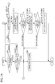
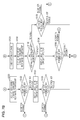
- FIG. 7A is a flowchart for illustrating alarming processing at the time of communication failure
- FIG. 7B is a flowchart for illustrating alarming processing at the time of communication failure
- FIG. 8 is a diagram illustrating a configuration of a communication terminal according to a comparative example.
- FIG. 9 is a diagram illustrating a display example of a display section of the communication terminal according to the comparative example.
- FIG. 1 is a diagram illustrating a configuration of the communication system 10 .
- the communication system 10 transmits and receives communication data through non-contact wireless communication.
- the communication system 10 includes a communication terminal 100 having a function of reader/writer, and an IC card 200 on which an IC chip is mounted.
- the communication terminal 100 is a mobile terminal, such as a mobile phone, for example.
- the communication system 10 may include an automatic ticket gate as a communication terminal having a function of reader/writer in place of the mobile terminal.
- the IC card 200 corresponds to the external apparatus.
- a mobile terminal such as a mobile phone on which an IC chip is mounted, etc., may be the external apparatus.
- a carrier wave having a specific frequency (for example, 13.56 MHz) is used for communication.
- the communication terminal 100 transmits a carrier wave including a carrier signal, and the IC card 200 that has received the carrier wave through a communication antenna 204 described later returns a response signal to the received carrier signal. Thereby, communication is performed between the communication terminal 100 and the IC card 200 .
- FIG. 2 is a circuit diagram illustrating the schematic configurations of the communication terminal 100 and the IC card 200 .
- the communication terminal 100 includes a modulation section 102 and a communication antenna 104 , which is an example of the communication section.
- the modulation section 102 receives a generation instruction of a carrier signal from a control section not illustrated in the figure, and generates a carrier signal in response to the instruction.
- the carrier signal can include, for example, various processing instructions to the IC card 200 and data to be processed.
- the communication antenna 104 has, for example, a coil having a predetermined inductance, and transmits the carrier wave including the carrier signal generated by the modulation section 102 . Also, the communication antenna 104 receives the response signal from the IC card 200 . In this regard, in FIG. 2 , an example in which the communication antenna 104 includes a resonance circuit including the coil and a capacitor is illustrated.
- the IC card 200 includes the communication antenna 204 and a load Z.
- the load Z equivalently illustrates the IC chip mounted on the IC card 200 .
- the communication antenna 204 includes, for example a coil having a predetermined inductance, and receives the carrier wave including the carrier signal transmitted from the communication antenna 104 . Also, the communication antenna 204 can make a response to the received carrier wave by load modulation.
- the communication terminal 100 detects a voltage of an antenna end P of the communication antenna 104 so as to make it possible to demodulate the response signal from the IC card 200 .
- a relative position (relative distance) of the communication terminal 100 with the IC card 200 is a suitable position for non-contact communication, it is possible to perform normal communication.
- the communication terminal 100 and the IC card 200 have portability, and thus the relative position of the communication terminal 100 with the IC card 200 tends to vary. Accordingly, non-contact communication sometimes fails depending on the relative position of the communication terminal 100 with the IC card 200 .
- non-contact communication sometimes fails. At the time of non-contact communication failure, it is necessary to get out of the communication failure state.
- a user of the communication terminal 100 and the IC card 200 is not aware of causes of the communication failure and how to resolve the failure. Accordingly, it is not possible for the user to suitably eliminate the communication failure state.
- a communication state is determined to be a communication error state
- processing is performed to give an alarm prompting the user to change the relative position of the communication terminal 100 with the IC card 200 on the basis of communication data at the time of communication error (for example, to move the communication terminal 100 ).
- the user is allowed to eliminate the communication error state by changing the relative position of the communication terminal 100 with the IC card 200 on the basis of the alarm contents.
- FIG. 3 is a diagram illustrating a detailed configuration of the communication terminal 100 .
- the communication terminal 100 includes an antenna coil 402 , a resonance capacitor 404 , a non-contact communication IC 406 , a mobile-phone control section 408 , which is an example of the control section, a voltage measurement section 410 , a display section 412 , a vibration section 414 , an LED 416 , which is an example of the light-emitting section, a speaker 418 , which is an example of the sound output section, and an acceleration section 420 , which is an example of a movement detection section.
- the antenna coil 402 and the resonance capacitor 404 constitute the communication antenna 104 in FIG. 2 . Also, the antenna coil 402 and the resonance capacitor 404 form a resonance circuit.
- the non-contact communication IC 406 performs a function of non-contact communication in the communication terminal 100 .
- the non-contact communication IC 406 determines whether data reception of the communication data from the IC card 200 is possible at the time of non-contact communication.
- FIG. 4 is a diagram illustrating a data structure of the communication data.
- the communication data received from the IC card 200 is packet data, and includes a preamble, a SYNC code, a data main body (also simply called “data”), and a CRC (Cyclic Redundancy Check).
- the preamble is disposed in order to obtain synchronization in non-contact communication.
- the SYNC code corresponds to the additional part, and is a code indicating a start position of the data main body.
- the data main body is actual data to be processed by the communication terminal 100 .
- the CRC detects an error in the communication data.
- the communication data is received in the order of the preamble, the SYNC code, the data main body, and the CRC. That is to say, the preamble is received first, and the CRC is received last.
- the non-contact communication IC 406 determines a communication error part in the communication data at the time of communication failure. Specifically, as illustrated in FIG. 5 , the non-contact communication IC 406 determines in which part of the packet data, that is to say, whether in the preamble, in the SYNC code, in the data main body, or in the CRC, the communication error has occurred. The non-contact communication IC 406 performs error determination in the order of the preamble, the SYNC code, the data main body, and the CRC. For example, if an error is determined in the preamble, error determination is not performed for the SYNC code, the data main body, and the CRC. Thereby, it becomes possible to shorten determination time. The non-contact communication IC 406 outputs a determination result to the mobile-phone control section 408 .
- FIG. 5 is a diagram illustrating examples of communication failures.
- Failure example 1 in FIG. 5 illustrates a case where a communication failure has occurred at preamble in packet data.
- Failure example 2 illustrates a case where a communication failure has occurred at SYNC code.
- Failure example 3 illustrates a case where a communication failure has occurred at data main body.
- Failure example 4 illustrates a case where a communication failure has occurred at CRC.
- the voltage measurement section 410 measures a voltage of the antenna end P in the communication antenna 104 . And the voltage measurement section 410 outputs a measurement result of the voltage at the antenna end P to the mobile-phone control section 408 .
- At least one of the display section 412 , the vibration section 414 , the LED 416 , and the speaker 418 functions as an alarming section that gives an alarm prompting the user to change a relative position of the communication terminal 100 with the IC card 200 (movement of the communication terminal 100 ).
- the display section 412 displays various kinds of information (messages).
- the display section 412 displays a message prompting the user to change the relative position of the communication terminal 100 with the IC card 200 at the time of non-contact communication failure with the IC card 200 .
- the display section 412 displays a message prompting the user to move the communication terminal 100 .
- FIG. 6 is a diagram illustrating states in which a message prompting the user to move the communication terminal 100 is displayed on a display section 412 at the time of non-contact communication failure.
- a message prompting the user to move the communication terminal 100 either upward, downward, rightward, or leftward is displayed.
- the difference between the display example 1 and the display example 3 is that in the case of the display example 1 , an amount of movement of the communication terminal 100 is small, whereas in the case of the display example 3 , an amount of movement of the communication terminal 100 is large.
- a message prompting the user to move the communication terminal 100 a little in the right direction is illustrated.
- the difference between the display example 2 and the display example 4 is that in the case of the display example 2 , an amount of movement of the communication terminal 100 is small, whereas in the case of the display example 4 , an amount of movement of the communication terminal 100 is large.
- the vibration section 414 has a vibrator, and vibrates a main body of the communication terminal 100 .
- the vibration section 414 vibrates at the time of non-contact communication failure so as to make it possible to give an alarm indicating a communication error state.
- the vibration section 414 may vibrate with a variety of degrees of vibration at the time of non-contact communication failure. For example, in the case of prompting the user to move the communication terminal 100 greatly, the vibration section 414 may vibrate greatly, whereas in the case of prompting the user to move the communication terminal 100 a little, the vibration section 414 may vibrate a little.
- the vibration section 414 may also change a vibration pattern (rhythm) in order to specify a movement direction of the communication terminal 100 .
- the LED 416 emits light in a plurality of colors.
- the LED 416 emits light at the time of non-contact communication failure so as to prompt the user to move the communication terminal 100 .
- the LED 416 may emit red light in order to prompt the user to move the communication terminal 100 in the left direction, and may emit blue light in order to prompt the user to move the communication terminal 100 in the right direction.
- the LED 416 may change a lighting pattern (for example, changing a lighting time period) in order to alarm a difference in the amount of movement of the communication terminal 100 .
- the speaker 418 outputs a sound.
- the speaker 418 outputs a sound (for example, a message voice displayed on the display section 412 in FIG. 6 ) at the time of non-contact communication failure in order to prompt the user to move the communication terminal 100 .
- the alarming section of the display section 412 gives an alarm prompting the user to change the relative position (movement the communication terminal 100 ) of the communication terminal 100 with the IC card 200 so that the user is aware of a solution of a non-contact communication failure. Accordingly, the user changes the relative position (moves the communication terminal 100 ) of the communication terminal 100 with the IC card 200 on the basis of the alarm contents so as to make it possible to suitably eliminate the communication error state.
- the acceleration section 420 detects movement, etc., of the communication terminal 100 after the alarming section of the display section 412 , etc., has given the alarm. For example, the acceleration section 420 detects an angle and movement of the communication terminal 100 when the user has moved the communication terminal 100 . And the acceleration section 420 outputs the detection result of the communication terminal 100 to the mobile-phone control section 408 .
- the mobile-phone control section 408 controls the entire mobile phone, which is a communication terminal 100 .
- the mobile-phone control section 408 determines a communication state of the communication antenna 104 with the IC card 200 on the basis of the determination result of receive data by the non-contact communication IC 406 . And if the mobile-phone control section 408 determines that the communication state is a communication error state, the mobile-phone control section causes the alarming section of the display section 412 , etc., to give an alarm prompting the user to change the relative position (movement of the communication terminal 100 ) of the communication terminal 100 with the IC card 200 on the basis of the communication data at the time of communication error. Thereby, the user changes the relative position (moves the communication terminal 100 ) of the communication terminal 100 with the IC card 200 on the basis of the alarm contents.
- the mobile-phone control section 408 gives an alarm with varying an amount of change (amount of movement) of the relative position of the communication terminal 100 with the IC card 200 in accordance with the communication error part in the packet data in FIG. 4 . Specifically, the mobile-phone control section 408 determines the amount of movement of the communication terminal 100 in the case of a communication error in a part having an early reception order from the IC card 200 of the packet data (for example, the preamble) to be greater than the amount of movement of the communication terminal 100 in the case of a communication error in a part having a late reception order (for example, the CRC).
- the packet data in FIG. 4 is received in the order of the preamble, the SYNC code, the data main body, and the CRC.
- the non-contact communication IC 406 performs error determination in the order of the preamble, the SYNC code, the data main body, and the CRC.
- a communication error in the SYNC it is possible to assume that there is a high possibility that a communication error also occurs in the data main body and the CRC, and thus it is possible to assume that the communication state between the communication terminal 100 and the IC card 200 is bad.
- an alarm is given to move the communication terminal 100 a little, and in the case of a communication error in a preamble or a SYNC, an alarm is given to move the communication terminal 100 greatly. Accordingly, an alarm is given such that the amount of movement of the communication terminal 100 is changed in accordance with the communication error part in packet data so that the user is allowed to suitably resolve the communication error state.
- the mobile-phone control section 408 determines that the communication error continues after the acceleration section 420 has detected movement of the communication terminal 100 , the mobile-phone control section 408 causes the alarming section to give an alarm to move in a direction different from the movement direction detected by the acceleration section 420 (for example, in the opposite direction), to the display section 412 , etc.
- the alarming section causes the alarming section to give an alarm to move in a direction different from the movement direction detected by the acceleration section 420 (for example, in the opposite direction), to the display section 412 , etc.
- the mobile-phone control section 408 determines that a communication error has occurred in a preamble or a SYNC code in packet data, the mobile-phone control section 408 causes the voltage measurement section 410 to measure a voltage of the antenna end P. At the same time, if the mobile-phone control section 408 determines that a communication error has occurred in a data main body or a CRC in the packet data, the mobile-phone control section 408 does not cause the voltage measurement section 410 to measure a voltage of the antenna end P. This is because in the case where a communication error occurs in a preamble or a SYNC code, a degree of communication error is large, and thus it is necessary to use a measurement voltage of the antenna end P in order to resolve the communication error.
- the mobile-phone control section 408 determines that the communication state is a communication error state
- the mobile-phone control section 408 causes the alarming section to give an alarm prompting the user to change the relative position of the communication terminal 100 with the IC card 200 to the display section 412 , etc., after the voltage measurement section 410 measures a voltage of the antenna end P. And if the voltage of the antenna end P measured again after the alarming section has give the alarm is lower than the voltage measured before the alarming, the mobile-phone control section 408 causes the alarming section to give an alarm with a changed alarming mode. For example, the mobile-phone control section 408 causes the alarming section to give an alarm for moving in a direction different from the movement direction of the communication terminal 100 by the alarming of immediately before. Thereby, it is possible to guide movement of the communication terminal 100 such that the communication antenna 104 is located at a suitable position for communicating with the IC card 200 , and thus it becomes easy to resolve the communication error state.
- the communication terminal 100 has a CPU (constitutes the above-described mobile-phone control section 408 ), a ROM, a RAM, etc.
- the CPU loads programs read from the ROM, or an external storage device, etc., onto the RAM, and executes the programs so as to achieve various kinds of processing (the alarming processing described later, etc., at the time of communication failure).
- the program can be recorded on a recording medium, or can be downloaded through the Internet.
- FIG. 7A and FIG. 7B are flowcharts for illustrating the alarming processing at the time of communication failure. This processing is achieved by the CPU executing the programs stored in the ROM, etc.
- the flowchart in FIG. 7A is started from a state in which the power to the communication terminal 100 is turned ON.
- the non-contact communication IC 406 of the communication terminal 100 determines whether there is a carrier wave from the IC card 200 or not (step S 102 ).
- the non-contact communication IC 406 waits for a carrier wave from the IC card 200 .
- the non-contact communication IC 406 determines whether data reception from the IC card 200 is possible or not (step S 104 ). That is to say, the non-contact communication IC 406 determines whether it is possible to receive a carrier wave signal including data or not.
- the non-contact communication IC 406 performs normal signal processing (step S 106 ). For example, the non-contact communication IC 406 performs signal processing of the received data. Thereby, this processing is terminated.
- the non-contact communication IC 406 performs error determination (step S 108 ). Specifically, the non-contact communication IC 406 determines in which part in the packet data ( FIG. 4 ) from the IC card 200 the error has occurred. At this time, the non-contact communication IC 406 performs error determination in the order of the preamble of the packet data, the SNYC code, the data main body, and the CRC (That is to say, in order of reception of the communication data).
- step S 108 if the CRC is determined to be an error (failure example 4 in FIG. 5 ), the mobile-phone control section 408 causes the display section 412 to display, for example, a message stating “move a little either upward, downward, rightward, or leftward” as illustrated in display example 1 in FIG. 6 (step S 110 ).
- the user who has viewed the message displayed in the display section 412 moves the communication terminal 100 either upward, downward, rightward, or leftward in order to resolve the communication failure state. In this regard, in which direction the user has moved the communication terminal 100 is detected by the acceleration section 420 .
- non-contact communication IC 406 determines again whether data reception from the IC card 200 is possible or not (step S 112 ). Specifically, if the non-contact communication IC 406 detects movement of the communication terminal 100 after the display in step 110 , the non-contact communication IC 406 determines whether data reception is possible or not.
- step S 112 if the communication state has been improved by the movement of the communication terminal 100 , and thus it is determined that data reception is possible, the non-contact communication IC 406 performs the above-described signal processing in step S 106 .
- step S 112 if determined data reception is not possible after the movement of the communication terminal 100 , the mobile-phone control section 408 causes the display section 412 to display a message stating “move a little” in the opposite direction to the direction moved immediately before (step S 114 ).
- the mobile-phone control section 408 causes the display section 412 to display a message stating “move a little in the right direction”. The user who has viewed the message displayed on the display section 412 moves the communication terminal 100 in the right direction in order to resolve the communication failure state.
- the non-contact communication IC 406 determines whether data reception from the IC card 200 is possible or not in the same manner in step S 112 (step S 116 ). And in step S 116 , if determined that the data reception is possible, the non-contact communication IC 406 performs the signal processing in step S 106 .
- step S 116 if determined that the data reception is not possible, the mobile-phone control section 408 causes the display section 412 to display a communication failure (for example, display in FIG. 9 ) (step S 118 ).
- a communication failure for example, display in FIG. 9
- step S 116 if determined that data reception is not possible, the error determination in step S 108 may be repeated again in place of the display of the communication failure.
- step S 108 if the data main body is determined to be in an error state (failure example 3 in FIG. 5 ), the mobile-phone control section 408 causes the display section 412 to display a message stating “move either upward, downward, rightward, or leftward” as illustrated in the display example 3 in FIG. 6 , for example (step S 120 ).
- the message contents displayed in step S 120 is different from the message contents displayed in step S 110 , and prompts the user to move the communication terminal 100 greatly.
- the non-contact communication IC 406 determines again whether data reception from the IC card 200 is possible or not (step S 122 ). In step S 122 , if determined that data reception is possible as a result of the movement of the communication terminal 100 , the non-contact communication IC 406 performs the above-described signal processing in step S 106 .
- step S 122 if determined that data reception is not possible after the movement of the communication terminal 100 , the mobile-phone control section 408 causes the display section 412 to display a message stating “move” in the opposite direction to the direction of the immediate movement (step S 124 ). For example, after the display in step S 120 , if the acceleration section 420 detects movement of the communication terminal 100 in the left direction, as illustrated in the display example 4 in FIG. 6 , the mobile-phone control section 408 causes the display section 412 to display a message stating “move in the right direction”.
- step S 126 the non-contact communication IC 406 determines whether data reception from the IC card 200 is possible or not. And in step S 126 , if determined that data reception is possible, the non-contact communication IC 406 performs the signal processing in step S 106 .
- step S 126 if determined that data reception is not possible, the non-contact communication IC 406 performs the error determination in step 108 again.
- the reason for performing the error determination again is that the failure in the data reception might be caused by the occurrence of an error in a part other than the data main body in the packet data (for example, CRC), and thus it is necessary to resolve this error.
- step S 108 if determined that the SNYC code or the preamble in the packet data is an error (the failure example 1 and the failure example 2 in FIG. 5 ), the voltage measurement section 410 checks a voltage of the antenna end P of the communication antenna 104 (step S 128 ).
- the mobile-phone control section 408 causes the display section 412 to display a message stating “move either upward, downward, rightward, or leftward” in the same manner as the above-described step S 120 (step S 130 ).
- the user moves the communication terminal 100 .
- the voltage measurement section 410 determines whether the voltage of the antenna end P increases or decreases as a result of the movement of the communication terminal 100 (step S 132 ).
- step S 132 if determined that the voltage of the antenna end P has decreased, the mobile-phone control section 408 causes the display section 412 to display a message stating “please move” in an opposite direction to the movement direction of immediately before (step S 134 ). For example, after the display in step S 130 , if the acceleration section 420 detects movement of the communication terminal 100 in the left direction, the mobile-phone control section 408 causes the display section 412 to display a message stating “move in the right direction”.
- the non-contact communication IC 406 determines again whether data reception from the IC card 200 is possible or not (step S 136 ). In step S 136 , if determined that data reception is possible by movement of the communication terminal 100 , the non-contact communication IC 406 performs the signal processing in the above-described step S 106 .
- step S 136 if determined that data reception is not possible even when the communication terminal 100 has been moved, the non-contact communication IC 406 performs the error determination in step 108 again.
- the reason for performing the error determination again is that the failure in the data reception might be caused by the occurrence of an error in a part other than the SNYC part and the preamble part in the packet data (the CRC part, for example), and thus it is necessary to resolve this error.
- step S 132 if determined that the voltage of the antenna end P has increased, the non-contact communication IC 406 determines again whether data reception from the IC card 200 is possible or not (step S 138 ). In step S 138 , if determined that data reception is possible, the non-contact communication IC 406 performs the above-described signal processing in step S 106 .
- step S 136 if determined that data reception is not possible, the non-contact communication IC 406 performs the error determination again in step 108 in the same manner as step S 136 .
- the display section 412 by causing the display section 412 to display a message to move the communication terminal 100 at the time of non-contact communication failure ( FIG. 6 ), it is possible to prompt the user to move the communication terminal 100 . Accordingly, the user moves the communication terminal 100 to a suitable position so that it becomes possible to perform suitable recovery at the time of communication failure.
- the display section 412 is caused to display a message in order to prompt the user to move the communication terminal 100 at the time of communication failure.
- an alarm for moving the communication terminal 100 may be given by sound output from the speaker 418 , lighting of the LED 416 , vibration of the vibration section 414 , etc.
- an alarm may be given by a combination of a plurality of sections, the display section 412 , the speaker 418 , the LED 416 , the vibration section 414 (for example, display of the display section 412 and lighting of the LED 416 ).
- a communication state of the communication antenna 104 with the IC card is determined. If determined that the communication state is a communication error state, the alarming section, such as a display section 412 , etc., gives an alarm prompting the user to change the relative position of the communication terminal 100 and the IC card 200 on the basis of the communication data at the time of communication error.
- the alarming section such as a display section 412 , etc.
- the user becomes aware of a countermeasure against the non-contact communication failure by the alarm contents from the alarming section. Accordingly, the user changes the relative position of the communication terminal 100 with the IC card 200 (moves the communication terminal 100 ) on the basis of the alarm contents so as to make it possible to suitably resolve the communication error state.
- FIG. 8 is a diagram illustrating a configuration of a communication terminal according to the comparative example.
- FIG. 9 is a diagram illustrating a display example of a display section of the communication terminal according to the comparative example.
- a display section 712 of a communication terminal 700 according to the comparative example displays a message (a communication error message) illustrated in FIG. 9 at the time of non-contact communication failure. Accordingly, the user who has seen the message in FIG. 9 is aware of a communication error state, but is not aware of a cause and a recovery method of the communication error. It is therefore difficult for the user to suitably resolve the communication error state at the time of the occurrence of a communication error.
- a message prompting the user to move the communication terminal 100 is displayed in order to resolve the communication error. Accordingly, unlike the display illustrated in FIG. 9 , the user is allowed to be aware of a specific countermeasure, and thus it becomes easy for the user to resolve the communication error state.
- the measurement result of the voltage measurement section 410 is checked, and is reported to the alarming section, and thus it is possible to move the communication terminal 100 such that the communication antenna 104 is located at a suitable position.
- the communication terminal may be a digital camera, a PDA, a game machine, an electronic dictionary, a tablet, etc., having a function of reader/writer and an alarming section.
- steps illustrated in the flowcharts of the above-described embodiment include processing that is processed in time series in accordance with the described sequence as a matter of course. Also, the steps include processing that is not necessarily performed in time series, but is performed in parallel or individually. Also, it goes without saying that it is possible to suitably change processing sequence even in the steps that are processed in time series depending on the circumstances.
- a communication terminal including:
- a communication section configured to perform non-contact communication with an external apparatus
- control section configured to determine a communication state of the communication section with the external apparatus, and if the communication state is determined to be a communication error state, the control section configured to cause the alarming section to give an alarm prompting a user to change a relative position of the communication terminal with the external apparatus on the basis of communication data at the time of the communication error.
- the communication data is packet data received from the external apparatus
- control section changes a displacement of the relative position in accordance with a communication error part in the packet data.
- control section causes the alarming section to give an alarm so as to determine the displacement of the relative position in the case of the communication error in an earlier part in a reception order from the external apparatus of the packet data to be larger than the displacement of the relative position in the case of the communication error in a later part in the reception order.
- the communication terminal according to (3) further including a voltage measurement section configured to measure a voltage in the communication section, wherein the packet data includes a data main body having a late order in the reception order and an additional part having an early order in the reception order and indicating a start position of the data main body, and
- control section determines that the communication error occurs in the additional part among the data main body and the additional part, the control section causes the voltage measurement section to measure the voltage.
- control section causes the alarming section to give an alarm prompting the user to change the relative position after the measurement of the voltage by the voltage measurement section, and
- the control section causes the alarming section to alarm in a different alarming mode.
- the communication terminal according to (6) further including a movement detection section configured to detect the movement of the communication terminal after the alarming section gives the alarm, wherein if the control section determines that the communication error continues after the movement detection by the movement detection section, the control section causes the alarming section to alarm movement to a different direction from the movement direction detected by the movement detection section.
- control section determines that the communication error continues after the movement detection by the movement detection section, the control section causes the alarming section to alarm movement to the opposite direction to the movement direction detected by the movement detection section.
- the alarming section is at least one of a display section displaying information, a light emitting section emitting light, a vibration section vibrating a main body of the terminal, and a sound outputting section outputting a sound.
- a method of communication including:
- the communication terminal determining a communication state with the external apparatus
- the communication state is determined to be a communication error state, causing an alarming section of the communication terminal to give an alarm prompting a user to change a relative position of the communication terminal with the external apparatus on the basis of communication data at the time of the communication error.
- a program for causing a computer to perform processing including:
- the communication terminal determining a communication state with the external apparatus
- the communication state is determined to be a communication error state, causing an alarming section of the communication terminal to give an alarm prompting a user to change a relative position of the communication terminal with the external apparatus on the basis of communication data at the time of the communication error.
Abstract
Description
- The present disclosure relates to a communication terminal, a communication method, and a program.
- In recent years, communication apparatuses, such as a non-contact type IC (Integrated Circuit) card, an RFID (Radio Frequency Identification) tag, or a mobile phone including a non-contact type IC chip, etc., (in the following, referred to as “IC cards”.) have become widespread. These apparatuses are capable of performing non-contact communication with a reader/writer (or a communication terminal including a reader/writer, which is simply referred to as a “reader/writer” hereinafter).
- A communication apparatus, such as a reader/writer, an IC card, or the like, uses a carrier wave having a specific frequency, for example, 13.56 MHz, etc. Specifically, a reader/writer transmits a carrier wave including a carrier signal, and an IC card that receives the carrier wave through an antenna returns a response signal to the received carrier signal by load modulation. Thereby, communication is performed between the reader/writer and the IC card.
- A related-art technique has been disclosed in Japanese Unexamined Patent Application Publication No. 2010-211577, for example.
- Incidentally, at least either one of a reader/writer or an IC card that performs non-contact communication is not fixed, and thus is movable. Thus, non-contact communication sometimes fails depending on a relative position of the reader/writer and the IC card. In such a case, it is necessary for a user of the reader/writer or the IC card to eliminate a communication failure state. However, there are cases where the user is not informed of causes of the communication failures and how to eliminate the causes. Accordingly, the user is not allowed to suitably get out of the communication failure state.
- Thus, it is desirable to provide a communication terminal, a communication method, and a program that is capable of suitably eliminating a communication failure state at the time of communication failure in non-contact communication.
- According to an embodiment of the present disclosure, there is provided a communication terminal including: a communication section configured to perform non-contact communication with an external apparatus; an alarming section; and a control section configured to determine a communication state of the communication section with the external apparatus, and if the communication state is determined to be a communication error state, the control section configured to cause the alarming section to give an alarm prompting the user to change a relative position of the communication terminal with the external apparatus on the basis of communication data at the time of the communication error.
- Also, according to another embodiment of the present disclosure, there is provided a method of communication, including: a communication terminal performing non-contact communication with an external apparatus; the communication terminal determining a communication state with the external apparatus; and if the communication state is determined to be a communication error state, causing an alarming section of the communication terminal to give an alarm prompting the user to change a relative position of the communication terminal with the external apparatus on the basis of communication data at the time of the communication error.
- Also, according to another embodiment of the present disclosure, there is provided a program for causing a computer to perform processing including: a communication terminal performing non-contact communication with an external apparatus; the communication terminal determining a communication state with the external apparatus; and if the communication state is determined to be a communication error state, causing an alarming section of the communication terminal to give an alarm prompting the user to change a relative position of the communication terminal with the external apparatus on the basis of communication data at the time of the communication error.
- As described above, by the present disclosure, it is possible for a user, etc., to suitably eliminate a communication failure state at the time of communication failure in non-contact communication.
-
FIG. 1 is a diagram illustrating a configuration of a communication system; -
FIG. 2 is a circuit diagram illustrating schematic configurations of a communication terminal and an IC card; -
FIG. 3 is a diagram illustrating a detailed configuration of the communication terminal; -
FIG. 4 is a diagram illustrating a data structure of communication data; -
FIG. 5 is a diagram illustrating examples of communication failures; -
FIG. 6 is a diagram illustrating states in which a message prompting a user to change a relative position of the communication terminal is displayed on a display section at the time of non-contact communication failure; -
FIG. 7A is a flowchart for illustrating alarming processing at the time of communication failure; -
FIG. 7B is a flowchart for illustrating alarming processing at the time of communication failure; -
FIG. 8 is a diagram illustrating a configuration of a communication terminal according to a comparative example; and -
FIG. 9 is a diagram illustrating a display example of a display section of the communication terminal according to the comparative example. - In the following, detailed descriptions will be given of preferred embodiments of the present disclosure with reference to the attached drawings.
- In this regard, in this specification and the drawings, a same reference numeral is given to a component having a substantially same functional configuration, and thus a duplicated description will be omitted.
- In this regard, the descriptions will be given in the following order.
- 1. Overview of Communication System
- 2. Configuration of Communication Terminal
- 3. Alarming Processing at the Time of Communication Failure
- 4. Summary
- A description will be given of a
communication system 10 according to the present embodiment with reference toFIG. 1 .FIG. 1 is a diagram illustrating a configuration of thecommunication system 10. - The
communication system 10 transmits and receives communication data through non-contact wireless communication. Thecommunication system 10 includes acommunication terminal 100 having a function of reader/writer, and anIC card 200 on which an IC chip is mounted. In the present embodiment, thecommunication terminal 100 is a mobile terminal, such as a mobile phone, for example. In this regard, thecommunication system 10 may include an automatic ticket gate as a communication terminal having a function of reader/writer in place of the mobile terminal. Also, in the present embodiment, theIC card 200 corresponds to the external apparatus. However, a mobile terminal, such as a mobile phone on which an IC chip is mounted, etc., may be the external apparatus. - In the
communication system 10, a carrier wave having a specific frequency (for example, 13.56 MHz) is used for communication. Specifically, thecommunication terminal 100 transmits a carrier wave including a carrier signal, and theIC card 200 that has received the carrier wave through acommunication antenna 204 described later returns a response signal to the received carrier signal. Thereby, communication is performed between thecommunication terminal 100 and theIC card 200. - Next, a description will be given of schematic configurations of the
communication terminal 100 and theIC card 200 with reference toFIG. 2 .FIG. 2 is a circuit diagram illustrating the schematic configurations of thecommunication terminal 100 and theIC card 200. - As illustrated in
FIG. 2 , thecommunication terminal 100 includes amodulation section 102 and acommunication antenna 104, which is an example of the communication section. - The
modulation section 102 receives a generation instruction of a carrier signal from a control section not illustrated in the figure, and generates a carrier signal in response to the instruction. In this regard, the carrier signal can include, for example, various processing instructions to theIC card 200 and data to be processed. - The
communication antenna 104 has, for example, a coil having a predetermined inductance, and transmits the carrier wave including the carrier signal generated by themodulation section 102. Also, thecommunication antenna 104 receives the response signal from theIC card 200. In this regard, inFIG. 2 , an example in which thecommunication antenna 104 includes a resonance circuit including the coil and a capacitor is illustrated. - As illustrated in
FIG. 2 , theIC card 200 includes thecommunication antenna 204 and a load Z. The load Z equivalently illustrates the IC chip mounted on theIC card 200. - The
communication antenna 204 includes, for example a coil having a predetermined inductance, and receives the carrier wave including the carrier signal transmitted from thecommunication antenna 104. Also, thecommunication antenna 204 can make a response to the received carrier wave by load modulation. - In this regard, the
communication terminal 100 detects a voltage of an antenna end P of thecommunication antenna 104 so as to make it possible to demodulate the response signal from theIC card 200. - Incidentally, in the
communication system 10, if a relative position (relative distance) of thecommunication terminal 100 with theIC card 200 is a suitable position for non-contact communication, it is possible to perform normal communication. However, thecommunication terminal 100 and theIC card 200 have portability, and thus the relative position of thecommunication terminal 100 with theIC card 200 tends to vary. Accordingly, non-contact communication sometimes fails depending on the relative position of thecommunication terminal 100 with theIC card 200. - For example, in the case where the distance between the
communication terminal 100 and theIC card 200 is out of a proper distance suitable for non-contact communication, or in the case where thecommunication terminal 100 and theIC card 200 are out of alignment in position, etc., non-contact communication sometimes fails. At the time of non-contact communication failure, it is necessary to get out of the communication failure state. However, there are cases where a user of thecommunication terminal 100 and theIC card 200 is not aware of causes of the communication failure and how to resolve the failure. Accordingly, it is not possible for the user to suitably eliminate the communication failure state. - Thus, in order to address the above-described problems, in the
communication system 10 according to the present embodiment, if a communication state is determined to be a communication error state, processing (alarming processing at the time of communication failure) is performed to give an alarm prompting the user to change the relative position of thecommunication terminal 100 with theIC card 200 on the basis of communication data at the time of communication error (for example, to move the communication terminal 100). Thereby, the user is allowed to eliminate the communication error state by changing the relative position of thecommunication terminal 100 with theIC card 200 on the basis of the alarm contents. In this regard, details of the alarming processing at the time of communication failure will be described later. - A description will be given of a detailed configuration of the
communication terminal 100 according to the present embodiment with reference toFIG. 3 .FIG. 3 is a diagram illustrating a detailed configuration of thecommunication terminal 100. - As illustrated in
FIG. 3 , thecommunication terminal 100 includes anantenna coil 402, aresonance capacitor 404, anon-contact communication IC 406, a mobile-phone control section 408, which is an example of the control section, avoltage measurement section 410, adisplay section 412, avibration section 414, anLED 416, which is an example of the light-emitting section, aspeaker 418, which is an example of the sound output section, and anacceleration section 420, which is an example of a movement detection section. - The
antenna coil 402 and theresonance capacitor 404 constitute thecommunication antenna 104 inFIG. 2 . Also, theantenna coil 402 and theresonance capacitor 404 form a resonance circuit. - The
non-contact communication IC 406 performs a function of non-contact communication in thecommunication terminal 100. Thenon-contact communication IC 406 determines whether data reception of the communication data from theIC card 200 is possible at the time of non-contact communication. - Here, a description will be given of communication data that is received by the
communication terminal 100 from theIC card 200 with reference toFIG. 4 .FIG. 4 is a diagram illustrating a data structure of the communication data. As illustrated inFIG. 4 , the communication data received from theIC card 200 is packet data, and includes a preamble, a SYNC code, a data main body (also simply called “data”), and a CRC (Cyclic Redundancy Check). - The preamble is disposed in order to obtain synchronization in non-contact communication. The SYNC code corresponds to the additional part, and is a code indicating a start position of the data main body. The data main body is actual data to be processed by the
communication terminal 100. The CRC detects an error in the communication data. In this regard, the communication data is received in the order of the preamble, the SYNC code, the data main body, and the CRC. That is to say, the preamble is received first, and the CRC is received last. - The
non-contact communication IC 406 determines a communication error part in the communication data at the time of communication failure. Specifically, as illustrated inFIG. 5 , thenon-contact communication IC 406 determines in which part of the packet data, that is to say, whether in the preamble, in the SYNC code, in the data main body, or in the CRC, the communication error has occurred. Thenon-contact communication IC 406 performs error determination in the order of the preamble, the SYNC code, the data main body, and the CRC. For example, if an error is determined in the preamble, error determination is not performed for the SYNC code, the data main body, and the CRC. Thereby, it becomes possible to shorten determination time. Thenon-contact communication IC 406 outputs a determination result to the mobile-phone control section 408. -
FIG. 5 is a diagram illustrating examples of communication failures. Failure example 1 inFIG. 5 illustrates a case where a communication failure has occurred at preamble in packet data. Failure example 2 illustrates a case where a communication failure has occurred at SYNC code. Failure example 3 illustrates a case where a communication failure has occurred at data main body. Failure example 4 illustrates a case where a communication failure has occurred at CRC. - The
voltage measurement section 410 measures a voltage of the antenna end P in thecommunication antenna 104. And thevoltage measurement section 410 outputs a measurement result of the voltage at the antenna end P to the mobile-phone control section 408. - In the present embodiment, at least one of the
display section 412, thevibration section 414, theLED 416, and thespeaker 418 functions as an alarming section that gives an alarm prompting the user to change a relative position of thecommunication terminal 100 with the IC card 200 (movement of the communication terminal 100). - The
display section 412 displays various kinds of information (messages). Thedisplay section 412 displays a message prompting the user to change the relative position of thecommunication terminal 100 with theIC card 200 at the time of non-contact communication failure with theIC card 200. For example, as illustrated inFIG. 6 , thedisplay section 412 displays a message prompting the user to move thecommunication terminal 100. -
FIG. 6 is a diagram illustrating states in which a message prompting the user to move thecommunication terminal 100 is displayed on adisplay section 412 at the time of non-contact communication failure. In a display example 1 and a display example 3 inFIG. 6 , a message prompting the user to move thecommunication terminal 100 either upward, downward, rightward, or leftward is displayed. The difference between the display example 1 and the display example 3 is that in the case of the display example 1, an amount of movement of thecommunication terminal 100 is small, whereas in the case of the display example 3, an amount of movement of thecommunication terminal 100 is large. Also, in a display example 2 and a display example 4, a message prompting the user to move the communication terminal 100 a little in the right direction is illustrated. The difference between the display example 2 and the display example 4 is that in the case of the display example 2, an amount of movement of thecommunication terminal 100 is small, whereas in the case of the display example 4, an amount of movement of thecommunication terminal 100 is large. - The
vibration section 414 has a vibrator, and vibrates a main body of thecommunication terminal 100. Thevibration section 414 vibrates at the time of non-contact communication failure so as to make it possible to give an alarm indicating a communication error state. Also, thevibration section 414 may vibrate with a variety of degrees of vibration at the time of non-contact communication failure. For example, in the case of prompting the user to move thecommunication terminal 100 greatly, thevibration section 414 may vibrate greatly, whereas in the case of prompting the user to move the communication terminal 100 a little, thevibration section 414 may vibrate a little. Also, thevibration section 414 may also change a vibration pattern (rhythm) in order to specify a movement direction of thecommunication terminal 100. - The
LED 416 emits light in a plurality of colors. TheLED 416 emits light at the time of non-contact communication failure so as to prompt the user to move thecommunication terminal 100. For example, theLED 416 may emit red light in order to prompt the user to move thecommunication terminal 100 in the left direction, and may emit blue light in order to prompt the user to move thecommunication terminal 100 in the right direction. Also, theLED 416 may change a lighting pattern (for example, changing a lighting time period) in order to alarm a difference in the amount of movement of thecommunication terminal 100. - The
speaker 418 outputs a sound. Thespeaker 418 outputs a sound (for example, a message voice displayed on thedisplay section 412 inFIG. 6 ) at the time of non-contact communication failure in order to prompt the user to move thecommunication terminal 100. - In this manner, the alarming section of the
display section 412, etc., gives an alarm prompting the user to change the relative position (movement the communication terminal 100) of thecommunication terminal 100 with theIC card 200 so that the user is aware of a solution of a non-contact communication failure. Accordingly, the user changes the relative position (moves the communication terminal 100) of thecommunication terminal 100 with theIC card 200 on the basis of the alarm contents so as to make it possible to suitably eliminate the communication error state. - The
acceleration section 420 detects movement, etc., of thecommunication terminal 100 after the alarming section of thedisplay section 412, etc., has given the alarm. For example, theacceleration section 420 detects an angle and movement of thecommunication terminal 100 when the user has moved thecommunication terminal 100. And theacceleration section 420 outputs the detection result of thecommunication terminal 100 to the mobile-phone control section 408. - The mobile-
phone control section 408 controls the entire mobile phone, which is acommunication terminal 100. The mobile-phone control section 408 determines a communication state of thecommunication antenna 104 with theIC card 200 on the basis of the determination result of receive data by thenon-contact communication IC 406. And if the mobile-phone control section 408 determines that the communication state is a communication error state, the mobile-phone control section causes the alarming section of thedisplay section 412, etc., to give an alarm prompting the user to change the relative position (movement of the communication terminal 100) of thecommunication terminal 100 with theIC card 200 on the basis of the communication data at the time of communication error. Thereby, the user changes the relative position (moves the communication terminal 100) of thecommunication terminal 100 with theIC card 200 on the basis of the alarm contents. - The mobile-
phone control section 408 gives an alarm with varying an amount of change (amount of movement) of the relative position of thecommunication terminal 100 with theIC card 200 in accordance with the communication error part in the packet data inFIG. 4 . Specifically, the mobile-phone control section 408 determines the amount of movement of thecommunication terminal 100 in the case of a communication error in a part having an early reception order from theIC card 200 of the packet data (for example, the preamble) to be greater than the amount of movement of thecommunication terminal 100 in the case of a communication error in a part having a late reception order (for example, the CRC). - Here, a description will be given of a reason for giving an alarm by varying the amount of movement of the
communication terminal 100 in accordance with a communication error part in the packet data. As described above, the packet data inFIG. 4 is received in the order of the preamble, the SYNC code, the data main body, and the CRC. Thenon-contact communication IC 406 performs error determination in the order of the preamble, the SYNC code, the data main body, and the CRC. And in the case of a communication error in the SYNC, it is possible to assume that there is a high possibility that a communication error also occurs in the data main body and the CRC, and thus it is possible to assume that the communication state between thecommunication terminal 100 and theIC card 200 is bad. On the other hand, in the case of a communication error in the CRC, there is no error in the preamble, the SYNC code, the data main body that were determined before, and thus it is possible to assume that a degree of the communication error is smaller than that of a communication error in the preamble. On the contrary, it is possible to say that the communication state is very bad in the case of a communication error in the preamble and the SYNC code. - Thus, in the
communication terminal 100 according to the present embodiment, in the case of a communication error in a CRC, an alarm is given to move the communication terminal 100 a little, and in the case of a communication error in a preamble or a SYNC, an alarm is given to move thecommunication terminal 100 greatly. Accordingly, an alarm is given such that the amount of movement of thecommunication terminal 100 is changed in accordance with the communication error part in packet data so that the user is allowed to suitably resolve the communication error state. - If the mobile-
phone control section 408 determines that the communication error continues after theacceleration section 420 has detected movement of thecommunication terminal 100, the mobile-phone control section 408 causes the alarming section to give an alarm to move in a direction different from the movement direction detected by the acceleration section 420 (for example, in the opposite direction), to thedisplay section 412, etc. Thereby, even if the communication error is not resolved by the movement of thecommunication terminal 100 after the immediate alarming, it is possible to resolve the communication error by the user moving thecommunication terminal 100 in a direction different from the movement direction immediately before. In particular, by giving an alarm to prompt the user to move to the opposite position, it is possible to effectively resolve the communication error state in the case where the movement immediately before is the movement that deteriorates the communication error state. - If the mobile-
phone control section 408 determines that a communication error has occurred in a preamble or a SYNC code in packet data, the mobile-phone control section 408 causes thevoltage measurement section 410 to measure a voltage of the antenna end P. At the same time, if the mobile-phone control section 408 determines that a communication error has occurred in a data main body or a CRC in the packet data, the mobile-phone control section 408 does not cause thevoltage measurement section 410 to measure a voltage of the antenna end P. This is because in the case where a communication error occurs in a preamble or a SYNC code, a degree of communication error is large, and thus it is necessary to use a measurement voltage of the antenna end P in order to resolve the communication error. - When the mobile-
phone control section 408 determines that the communication state is a communication error state, the mobile-phone control section 408 causes the alarming section to give an alarm prompting the user to change the relative position of thecommunication terminal 100 with theIC card 200 to thedisplay section 412, etc., after thevoltage measurement section 410 measures a voltage of the antenna end P. And if the voltage of the antenna end P measured again after the alarming section has give the alarm is lower than the voltage measured before the alarming, the mobile-phone control section 408 causes the alarming section to give an alarm with a changed alarming mode. For example, the mobile-phone control section 408 causes the alarming section to give an alarm for moving in a direction different from the movement direction of thecommunication terminal 100 by the alarming of immediately before. Thereby, it is possible to guide movement of thecommunication terminal 100 such that thecommunication antenna 104 is located at a suitable position for communicating with theIC card 200, and thus it becomes easy to resolve the communication error state. - The
communication terminal 100 has a CPU (constitutes the above-described mobile-phone control section 408), a ROM, a RAM, etc. The CPU loads programs read from the ROM, or an external storage device, etc., onto the RAM, and executes the programs so as to achieve various kinds of processing (the alarming processing described later, etc., at the time of communication failure). In this regard, the program can be recorded on a recording medium, or can be downloaded through the Internet. - A description will be given of alarming processing at the time of communication failure with reference to
FIG. 7A andFIG. 7B .FIG. 7A andFIG. 7B are flowcharts for illustrating the alarming processing at the time of communication failure. This processing is achieved by the CPU executing the programs stored in the ROM, etc. - The flowchart in
FIG. 7A is started from a state in which the power to thecommunication terminal 100 is turned ON. First, thenon-contact communication IC 406 of thecommunication terminal 100 determines whether there is a carrier wave from theIC card 200 or not (step S102). - If determined that there is no carrier wave from the
IC card 200 in step S102, thenon-contact communication IC 406 waits for a carrier wave from theIC card 200. - On the other hand, if determined that there is a carrier wave from the
IC card 200 in step S102, thenon-contact communication IC 406 determines whether data reception from theIC card 200 is possible or not (step S104). That is to say, thenon-contact communication IC 406 determines whether it is possible to receive a carrier wave signal including data or not. - If determined that data reception is possible in step S104, the
non-contact communication IC 406 performs normal signal processing (step S106). For example, thenon-contact communication IC 406 performs signal processing of the received data. Thereby, this processing is terminated. - If determined that data reception is not possible in step S104, the
non-contact communication IC 406 performs error determination (step S108). Specifically, thenon-contact communication IC 406 determines in which part in the packet data (FIG. 4 ) from theIC card 200 the error has occurred. At this time, thenon-contact communication IC 406 performs error determination in the order of the preamble of the packet data, the SNYC code, the data main body, and the CRC (That is to say, in order of reception of the communication data). - In step S108, if the CRC is determined to be an error (failure example 4 in
FIG. 5 ), the mobile-phone control section 408 causes thedisplay section 412 to display, for example, a message stating “move a little either upward, downward, rightward, or leftward” as illustrated in display example 1 inFIG. 6 (step S110). The user who has viewed the message displayed in thedisplay section 412 moves thecommunication terminal 100 either upward, downward, rightward, or leftward in order to resolve the communication failure state. In this regard, in which direction the user has moved thecommunication terminal 100 is detected by theacceleration section 420. - Next,
non-contact communication IC 406 determines again whether data reception from theIC card 200 is possible or not (step S112). Specifically, if thenon-contact communication IC 406 detects movement of thecommunication terminal 100 after the display in step 110, thenon-contact communication IC 406 determines whether data reception is possible or not. - In step S112, if the communication state has been improved by the movement of the
communication terminal 100, and thus it is determined that data reception is possible, thenon-contact communication IC 406 performs the above-described signal processing in step S106. - In step S112, if determined data reception is not possible after the movement of the
communication terminal 100, the mobile-phone control section 408 causes thedisplay section 412 to display a message stating “move a little” in the opposite direction to the direction moved immediately before (step S114). For example, if theacceleration section 420 detects that thecommunication terminal 100 has moved in the left direction after the display in step S110, as illustrated in the display example 2 inFIG. 6 , the mobile-phone control section 408 causes thedisplay section 412 to display a message stating “move a little in the right direction”. The user who has viewed the message displayed on thedisplay section 412 moves thecommunication terminal 100 in the right direction in order to resolve the communication failure state. - Next, the
non-contact communication IC 406 determines whether data reception from theIC card 200 is possible or not in the same manner in step S112 (step S116). And in step S116, if determined that the data reception is possible, thenon-contact communication IC 406 performs the signal processing in step S106. - In step S116, if determined that the data reception is not possible, the mobile-
phone control section 408 causes thedisplay section 412 to display a communication failure (for example, display inFIG. 9 ) (step S118). - Thereby, this processing in terminated, and the user retries movement. In this regard, in step S116, if determined that data reception is not possible, the error determination in step S108 may be repeated again in place of the display of the communication failure.
- In step S108, if the data main body is determined to be in an error state (failure example 3 in
FIG. 5 ), the mobile-phone control section 408 causes thedisplay section 412 to display a message stating “move either upward, downward, rightward, or leftward” as illustrated in the display example 3 inFIG. 6 , for example (step S120). The message contents displayed in step S120 is different from the message contents displayed in step S110, and prompts the user to move thecommunication terminal 100 greatly. - Next, the
non-contact communication IC 406 determines again whether data reception from theIC card 200 is possible or not (step S122). In step S122, if determined that data reception is possible as a result of the movement of thecommunication terminal 100, thenon-contact communication IC 406 performs the above-described signal processing in step S106. - In step S122, if determined that data reception is not possible after the movement of the
communication terminal 100, the mobile-phone control section 408 causes thedisplay section 412 to display a message stating “move” in the opposite direction to the direction of the immediate movement (step S124). For example, after the display in step S120, if theacceleration section 420 detects movement of thecommunication terminal 100 in the left direction, as illustrated in the display example 4 inFIG. 6 , the mobile-phone control section 408 causes thedisplay section 412 to display a message stating “move in the right direction”. - Next, in the same manner as step S122, the
non-contact communication IC 406 determines whether data reception from theIC card 200 is possible or not (step S126). And in step S126, if determined that data reception is possible, thenon-contact communication IC 406 performs the signal processing in step S106. - In step S126, if determined that data reception is not possible, the
non-contact communication IC 406 performs the error determination in step 108 again. The reason for performing the error determination again is that the failure in the data reception might be caused by the occurrence of an error in a part other than the data main body in the packet data (for example, CRC), and thus it is necessary to resolve this error. - In step S108, if determined that the SNYC code or the preamble in the packet data is an error (the failure example 1 and the failure example 2 in
FIG. 5 ), thevoltage measurement section 410 checks a voltage of the antenna end P of the communication antenna 104 (step S128). - Next, the mobile-
phone control section 408 causes thedisplay section 412 to display a message stating “move either upward, downward, rightward, or leftward” in the same manner as the above-described step S120 (step S130). Thereby, the user moves thecommunication terminal 100. When thecommunication terminal 100 is moved, thevoltage measurement section 410 determines whether the voltage of the antenna end P increases or decreases as a result of the movement of the communication terminal 100 (step S132). - In step S132, if determined that the voltage of the antenna end P has decreased, the mobile-
phone control section 408 causes thedisplay section 412 to display a message stating “please move” in an opposite direction to the movement direction of immediately before (step S134). For example, after the display in step S130, if theacceleration section 420 detects movement of thecommunication terminal 100 in the left direction, the mobile-phone control section 408 causes thedisplay section 412 to display a message stating “move in the right direction”. - Next, the
non-contact communication IC 406 determines again whether data reception from theIC card 200 is possible or not (step S136). In step S136, if determined that data reception is possible by movement of thecommunication terminal 100, thenon-contact communication IC 406 performs the signal processing in the above-described step S106. - In step S136, if determined that data reception is not possible even when the
communication terminal 100 has been moved, thenon-contact communication IC 406 performs the error determination in step 108 again. The reason for performing the error determination again is that the failure in the data reception might be caused by the occurrence of an error in a part other than the SNYC part and the preamble part in the packet data (the CRC part, for example), and thus it is necessary to resolve this error. - In step S132, if determined that the voltage of the antenna end P has increased, the
non-contact communication IC 406 determines again whether data reception from theIC card 200 is possible or not (step S138). In step S138, if determined that data reception is possible, thenon-contact communication IC 406 performs the above-described signal processing in step S106. - In step S136, if determined that data reception is not possible, the
non-contact communication IC 406 performs the error determination again in step 108 in the same manner as step S136. - According to the above-described present processing, by causing the
display section 412 to display a message to move thecommunication terminal 100 at the time of non-contact communication failure (FIG. 6 ), it is possible to prompt the user to move thecommunication terminal 100. Accordingly, the user moves thecommunication terminal 100 to a suitable position so that it becomes possible to perform suitable recovery at the time of communication failure. - In this regard, in this processing, the
display section 412 is caused to display a message in order to prompt the user to move thecommunication terminal 100 at the time of communication failure. However, the present disclosure is not limited to this. For example, an alarm for moving thecommunication terminal 100 may be given by sound output from thespeaker 418, lighting of theLED 416, vibration of thevibration section 414, etc. - Also, an alarm may be given by a combination of a plurality of sections, the
display section 412, thespeaker 418, theLED 416, the vibration section 414 (for example, display of thedisplay section 412 and lighting of the LED 416). - As described above, in the
communication terminal 100 according to the present embodiment, a communication state of thecommunication antenna 104 with the IC card is determined. If determined that the communication state is a communication error state, the alarming section, such as adisplay section 412, etc., gives an alarm prompting the user to change the relative position of thecommunication terminal 100 and theIC card 200 on the basis of the communication data at the time of communication error. The user becomes aware of a countermeasure against the non-contact communication failure by the alarm contents from the alarming section. Accordingly, the user changes the relative position of thecommunication terminal 100 with the IC card 200 (moves the communication terminal 100) on the basis of the alarm contents so as to make it possible to suitably resolve the communication error state. - Here, a description will be further given of effectiveness of the
communication terminal 100 according to the present embodiment in comparison with a comparative example illustrated inFIG. 8 andFIG. 9 .FIG. 8 is a diagram illustrating a configuration of a communication terminal according to the comparative example.FIG. 9 is a diagram illustrating a display example of a display section of the communication terminal according to the comparative example. - First, a description will be given of the comparative example. A
display section 712 of acommunication terminal 700 according to the comparative example displays a message (a communication error message) illustrated inFIG. 9 at the time of non-contact communication failure. Accordingly, the user who has seen the message inFIG. 9 is aware of a communication error state, but is not aware of a cause and a recovery method of the communication error. It is therefore difficult for the user to suitably resolve the communication error state at the time of the occurrence of a communication error. - In contrast, in the present embodiment illustrated in
FIG. 6 , a message prompting the user to move thecommunication terminal 100 is displayed in order to resolve the communication error. Accordingly, unlike the display illustrated inFIG. 9 , the user is allowed to be aware of a specific countermeasure, and thus it becomes easy for the user to resolve the communication error state. - Also, in the
communication terminal 100 according to the present embodiment, unlike the configuration of thecommunication terminal 700 illustrated inFIG. 8 , the measurement result of thevoltage measurement section 410 is checked, and is reported to the alarming section, and thus it is possible to move thecommunication terminal 100 such that thecommunication antenna 104 is located at a suitable position. - In the above, a detailed description has been given of preferred embodiments of the present disclosure with reference to the accompanying drawings. However, the present disclosure is not limited to such examples. It should be understood by those skilled in the art to which the present disclosure pertains that various changes and modifications may apparently occur within the spirit and the scope of the appended claims, and such changes and modifications may naturally fall within the spirit and the scope of the present disclosure.
- Also, in the above-described embodiment, a description has been given by taking a mobile phone or an automatic ticket gate as a communication terminal. However, the present embodiment is not limited to this. The communication terminal may be a digital camera, a PDA, a game machine, an electronic dictionary, a tablet, etc., having a function of reader/writer and an alarming section.
- Also, steps illustrated in the flowcharts of the above-described embodiment include processing that is processed in time series in accordance with the described sequence as a matter of course. Also, the steps include processing that is not necessarily performed in time series, but is performed in parallel or individually. Also, it goes without saying that it is possible to suitably change processing sequence even in the steps that are processed in time series depending on the circumstances.
- In this regard, it is also possible to configure this technique in the following manner.
- (1) A communication terminal including:
- a communication section configured to perform non-contact communication with an external apparatus;
- an alarming section; and
- a control section configured to determine a communication state of the communication section with the external apparatus, and if the communication state is determined to be a communication error state, the control section configured to cause the alarming section to give an alarm prompting a user to change a relative position of the communication terminal with the external apparatus on the basis of communication data at the time of the communication error.
- (2) The communication terminal according to (1),
- wherein the communication data is packet data received from the external apparatus, and
- the control section changes a displacement of the relative position in accordance with a communication error part in the packet data.
- (3) The communication terminal according to (2),
- wherein the control section causes the alarming section to give an alarm so as to determine the displacement of the relative position in the case of the communication error in an earlier part in a reception order from the external apparatus of the packet data to be larger than the displacement of the relative position in the case of the communication error in a later part in the reception order.
- (4) The communication terminal according to (3), further including a voltage measurement section configured to measure a voltage in the communication section, wherein the packet data includes a data main body having a late order in the reception order and an additional part having an early order in the reception order and indicating a start position of the data main body, and
- if the control section determines that the communication error occurs in the additional part among the data main body and the additional part, the control section causes the voltage measurement section to measure the voltage.
- (5) The communication terminal according to (4),
- wherein if the communication state is determined to be a communication error state, the control section causes the alarming section to give an alarm prompting the user to change the relative position after the measurement of the voltage by the voltage measurement section, and
- if the voltage measured again after the alarming by the alarming section is lower than the voltage measured before the alarming, the control section causes the alarming section to alarm in a different alarming mode.
- (6) The communication terminal according to any one of (1) to (5), wherein the control section causes the alarming section to give an alarm of movement of the communication terminal in a predetermined direction as the displacement of the relative position.
- (7) The communication terminal according to (6), further including a movement detection section configured to detect the movement of the communication terminal after the alarming section gives the alarm, wherein if the control section determines that the communication error continues after the movement detection by the movement detection section, the control section causes the alarming section to alarm movement to a different direction from the movement direction detected by the movement detection section.
- (8) The communication terminal according to (7),
- wherein if the control section determines that the communication error continues after the movement detection by the movement detection section, the control section causes the alarming section to alarm movement to the opposite direction to the movement direction detected by the movement detection section.
- (9) The communication terminal according to any one of (1) to (8),
- wherein the alarming section is at least one of a display section displaying information, a light emitting section emitting light, a vibration section vibrating a main body of the terminal, and a sound outputting section outputting a sound.
- (10) A method of communication, including:
- a communication terminal performing non-contact communication with an external apparatus;
- the communication terminal determining a communication state with the external apparatus; and
- if the communication state is determined to be a communication error state, causing an alarming section of the communication terminal to give an alarm prompting a user to change a relative position of the communication terminal with the external apparatus on the basis of communication data at the time of the communication error.
- (11) A program for causing a computer to perform processing including:
- a communication terminal performing non-contact communication with an external apparatus;
- the communication terminal determining a communication state with the external apparatus; and
- if the communication state is determined to be a communication error state, causing an alarming section of the communication terminal to give an alarm prompting a user to change a relative position of the communication terminal with the external apparatus on the basis of communication data at the time of the communication error.
- The present disclosure contains subject matter related to that disclosed in Japanese Priority Patent Application JP 2011-074425 filed in the Japan Patent Office on Mar. 30, 2011, the entire contents of which are hereby incorporated by reference.
Claims (11)
Applications Claiming Priority (2)
| Application Number | Priority Date | Filing Date | Title |
|---|---|---|---|
| JP2011-074425 | 2011-03-30 | ||
| JP2011074425A JP5670798B2 (en) | 2011-03-30 | 2011-03-30 | Communication terminal, communication method, and program |
Publications (2)
| Publication Number | Publication Date |
|---|---|
| US20120249337A1 true US20120249337A1 (en) | 2012-10-04 |
| US9083813B2 US9083813B2 (en) | 2015-07-14 |
Family
ID=45656451
Family Applications (1)
| Application Number | Title | Priority Date | Filing Date |
|---|---|---|---|
| US13/428,394 Active 2033-06-13 US9083813B2 (en) | 2011-03-30 | 2012-03-23 | Communication terminal, communication method, and program |
Country Status (5)
| Country | Link |
|---|---|
| US (1) | US9083813B2 (en) |
| EP (1) | EP2506543B1 (en) |
| JP (1) | JP5670798B2 (en) |
| CN (1) | CN102739853B (en) |
| TW (1) | TWI530139B (en) |
Cited By (2)
| Publication number | Priority date | Publication date | Assignee | Title |
|---|---|---|---|---|
| US20180013905A1 (en) * | 2015-04-06 | 2018-01-11 | Kyocera Document Solutions Inc. | Image formation apparatus |
| US10860814B2 (en) * | 2018-10-02 | 2020-12-08 | Capital One Services, Llc | Systems and methods for cryptographic authentication of contactless cards |
Families Citing this family (3)
| Publication number | Priority date | Publication date | Assignee | Title |
|---|---|---|---|---|
| JP6012204B2 (en) * | 2012-03-06 | 2016-10-25 | 株式会社メガチップス | POSITIONING SYSTEM, TERMINAL DEVICE, PROGRAM, AND POSITIONING METHOD |
| US9400904B2 (en) * | 2014-06-13 | 2016-07-26 | Verily Life Sciences Llc | System for aligning a handheld RFID reader |
| JP6381056B2 (en) * | 2015-01-08 | 2018-08-29 | Necディスプレイソリューションズ株式会社 | Portable terminal, data communication system, data communication method, program |
Citations (26)
| Publication number | Priority date | Publication date | Assignee | Title |
|---|---|---|---|---|
| US5029183A (en) * | 1989-06-29 | 1991-07-02 | Symbol Technologies, Inc. | Packet data communication network |
| US5602956A (en) * | 1993-01-11 | 1997-02-11 | Sony Corporation | Picture signal coding method, decoding method and picture signal recording medium |
| US5945660A (en) * | 1996-10-16 | 1999-08-31 | Matsushita Electric Industrial Co., Ltd. | Communication system for wireless bar code reader |
| US6307468B1 (en) * | 1999-07-20 | 2001-10-23 | Avid Identification Systems, Inc. | Impedance matching network and multidimensional electromagnetic field coil for a transponder interrogator |
| US6427065B1 (en) * | 1996-09-13 | 2002-07-30 | Hitachi, Ltd. | Power transmission system, IC card and information communication system using IC card |
| US6842606B1 (en) * | 1999-03-03 | 2005-01-11 | Kabushiki Kaisha Toshiba | Wireless information storage device and method |
| US20050048949A1 (en) * | 2003-08-25 | 2005-03-03 | Kabushiki Kaisha Toshiba | Wireless communication device and wireless communication method |
| US20060022815A1 (en) * | 2004-07-30 | 2006-02-02 | Fischer Jeffrey H | Interference monitoring in an RFID system |
| US20060052055A1 (en) * | 2004-09-08 | 2006-03-09 | Nokia Corporation | Electronic near field communication enabled multifunctional device and method of its operation |
| US20060160488A1 (en) * | 2005-01-17 | 2006-07-20 | Sony Ericsson Mobile Communications Japan, Inc. | Short-range wireless communication apparatus and cellular phone terminal |
| US20060239675A1 (en) * | 2004-05-31 | 2006-10-26 | Casio Computer Co., Ltd. | Information reception device, information transmission system, and information reception method |
| US20070141997A1 (en) * | 2005-12-15 | 2007-06-21 | Symbol Technologies, Inc. | Radio frequency identification (RFID) antenna integration techniques in mobile devices |
| US20070205283A1 (en) * | 2004-06-07 | 2007-09-06 | Nokia Corporation | Indicia reader with synchronized light source and associated methods and computer program product |
| US7319396B2 (en) * | 2004-08-16 | 2008-01-15 | Abr, Llc | RFID transducer alignment system |
| US20080093447A1 (en) * | 2006-09-29 | 2008-04-24 | Phillip Marc Johnson | Device and method for guiding a user to a communication position |
| US7433651B2 (en) * | 2000-10-24 | 2008-10-07 | Sony Corporation | Information processing apparatus and information processing method having communication function |
| US20090052426A1 (en) * | 2006-03-15 | 2009-02-26 | Freescale Semiconductor, Inc. | Method and apparatus for enhanced data rate adaptation and lower power control in a wlan semiconductor chip |
| US20090184161A1 (en) * | 2008-01-18 | 2009-07-23 | Sony Corporation | Remote control apparatus and communication system |
| US20090219142A1 (en) * | 2008-02-29 | 2009-09-03 | Ku Ja-Nam | Rfid system and method of transmitting large data of passive rfid |
| US20100068996A1 (en) * | 2008-09-15 | 2010-03-18 | Sony Ericsson Mobile Communications Ab | Electronic devices and methods that communicate via transferjet and nfc transmitter and receiver pairing |
| US20100207726A1 (en) * | 2009-02-11 | 2010-08-19 | Oberthur Technologies | Electronic Entity Capable of Communicating With a Reader and Method Used Within Such an Electronic Entity |
| US20100316171A1 (en) * | 2009-06-16 | 2010-12-16 | Sony Corporation | Data processing apparatus and method, receiving apparatus and method, synchronous detection apparatus and method, and computer program |
| US8014791B2 (en) * | 2008-06-30 | 2011-09-06 | Intelligent Sciences, Ltd. | Method and system for determining position of a wireless electronic device within a volume |
| US8138938B2 (en) * | 2008-10-28 | 2012-03-20 | The Boeing Company | Hand-held positioning interface for spatial query |
| US8384679B2 (en) * | 2008-12-23 | 2013-02-26 | Todd Robert Paleczny | Piezoelectric actuator arrangement |
| US8593255B2 (en) * | 2009-04-24 | 2013-11-26 | Nokia Corporation | Method and apparatus for providing user interaction via transponders |
Family Cites Families (11)
| Publication number | Priority date | Publication date | Assignee | Title |
|---|---|---|---|---|
| JP3111966B2 (en) * | 1998-01-30 | 2000-11-27 | 日本電気株式会社 | Mobile phone equipment |
| JP2005045557A (en) * | 2003-07-22 | 2005-02-17 | Sony Corp | Communication device |
| JP2007005999A (en) * | 2005-06-22 | 2007-01-11 | Denso Wave Inc | Communication apparatus and notification control method of communication apparatus |
| US7840237B2 (en) * | 2007-02-08 | 2010-11-23 | Microsoft Corporation | Enabling user interface elements based on short range wireless devices |
| JP5033532B2 (en) * | 2007-07-30 | 2012-09-26 | 京セラ株式会社 | Communication terminal |
| JP2009140406A (en) * | 2007-12-10 | 2009-06-25 | Sanden Corp | Noncontact ic chip reader/writer |
| KR101524616B1 (en) * | 2008-07-07 | 2015-06-02 | 엘지전자 주식회사 | Controlling a Mobile Terminal with a Gyro-Sensor |
| JP2010118773A (en) * | 2008-11-11 | 2010-05-27 | Toshiba Corp | Wireless communication terminal |
| JP5223736B2 (en) | 2009-03-11 | 2013-06-26 | パナソニック株式会社 | Information reader |
| US9455768B2 (en) * | 2009-09-24 | 2016-09-27 | Blackberry Limited | Communications device, method and system for establishing wireless communications between communications devices |
| JP2011074425A (en) | 2009-09-29 | 2011-04-14 | Sumitomo Electric Ind Ltd | Method for producing composite material, and composite material |
-
2011
- 2011-03-30 JP JP2011074425A patent/JP5670798B2/en active Active
-
2012
- 2012-02-22 EP EP12156554.3A patent/EP2506543B1/en active Active
- 2012-03-21 TW TW101109665A patent/TWI530139B/en active
- 2012-03-23 US US13/428,394 patent/US9083813B2/en active Active
- 2012-03-23 CN CN201210080531.7A patent/CN102739853B/en active Active
Patent Citations (28)
| Publication number | Priority date | Publication date | Assignee | Title |
|---|---|---|---|---|
| US5029183A (en) * | 1989-06-29 | 1991-07-02 | Symbol Technologies, Inc. | Packet data communication network |
| US5602956A (en) * | 1993-01-11 | 1997-02-11 | Sony Corporation | Picture signal coding method, decoding method and picture signal recording medium |
| US6427065B1 (en) * | 1996-09-13 | 2002-07-30 | Hitachi, Ltd. | Power transmission system, IC card and information communication system using IC card |
| US5945660A (en) * | 1996-10-16 | 1999-08-31 | Matsushita Electric Industrial Co., Ltd. | Communication system for wireless bar code reader |
| US6842606B1 (en) * | 1999-03-03 | 2005-01-11 | Kabushiki Kaisha Toshiba | Wireless information storage device and method |
| US6307468B1 (en) * | 1999-07-20 | 2001-10-23 | Avid Identification Systems, Inc. | Impedance matching network and multidimensional electromagnetic field coil for a transponder interrogator |
| US20020053973A1 (en) * | 1999-07-20 | 2002-05-09 | Ward William H. | Impedance matching network and multidimensional electromagnetic field coil for a transponder interrogator |
| US7433651B2 (en) * | 2000-10-24 | 2008-10-07 | Sony Corporation | Information processing apparatus and information processing method having communication function |
| US20050048949A1 (en) * | 2003-08-25 | 2005-03-03 | Kabushiki Kaisha Toshiba | Wireless communication device and wireless communication method |
| US20060239675A1 (en) * | 2004-05-31 | 2006-10-26 | Casio Computer Co., Ltd. | Information reception device, information transmission system, and information reception method |
| US20070205283A1 (en) * | 2004-06-07 | 2007-09-06 | Nokia Corporation | Indicia reader with synchronized light source and associated methods and computer program product |
| US20060022815A1 (en) * | 2004-07-30 | 2006-02-02 | Fischer Jeffrey H | Interference monitoring in an RFID system |
| US7319396B2 (en) * | 2004-08-16 | 2008-01-15 | Abr, Llc | RFID transducer alignment system |
| US20060052055A1 (en) * | 2004-09-08 | 2006-03-09 | Nokia Corporation | Electronic near field communication enabled multifunctional device and method of its operation |
| US20060160488A1 (en) * | 2005-01-17 | 2006-07-20 | Sony Ericsson Mobile Communications Japan, Inc. | Short-range wireless communication apparatus and cellular phone terminal |
| US20070141997A1 (en) * | 2005-12-15 | 2007-06-21 | Symbol Technologies, Inc. | Radio frequency identification (RFID) antenna integration techniques in mobile devices |
| US20090052426A1 (en) * | 2006-03-15 | 2009-02-26 | Freescale Semiconductor, Inc. | Method and apparatus for enhanced data rate adaptation and lower power control in a wlan semiconductor chip |
| US7769345B2 (en) * | 2006-09-29 | 2010-08-03 | Sony Ericsson Mobile Communications Ab | Device and method for guiding a user to a communication position |
| US20080093447A1 (en) * | 2006-09-29 | 2008-04-24 | Phillip Marc Johnson | Device and method for guiding a user to a communication position |
| US20090184161A1 (en) * | 2008-01-18 | 2009-07-23 | Sony Corporation | Remote control apparatus and communication system |
| US20090219142A1 (en) * | 2008-02-29 | 2009-09-03 | Ku Ja-Nam | Rfid system and method of transmitting large data of passive rfid |
| US8014791B2 (en) * | 2008-06-30 | 2011-09-06 | Intelligent Sciences, Ltd. | Method and system for determining position of a wireless electronic device within a volume |
| US20100068996A1 (en) * | 2008-09-15 | 2010-03-18 | Sony Ericsson Mobile Communications Ab | Electronic devices and methods that communicate via transferjet and nfc transmitter and receiver pairing |
| US8138938B2 (en) * | 2008-10-28 | 2012-03-20 | The Boeing Company | Hand-held positioning interface for spatial query |
| US8384679B2 (en) * | 2008-12-23 | 2013-02-26 | Todd Robert Paleczny | Piezoelectric actuator arrangement |
| US20100207726A1 (en) * | 2009-02-11 | 2010-08-19 | Oberthur Technologies | Electronic Entity Capable of Communicating With a Reader and Method Used Within Such an Electronic Entity |
| US8593255B2 (en) * | 2009-04-24 | 2013-11-26 | Nokia Corporation | Method and apparatus for providing user interaction via transponders |
| US20100316171A1 (en) * | 2009-06-16 | 2010-12-16 | Sony Corporation | Data processing apparatus and method, receiving apparatus and method, synchronous detection apparatus and method, and computer program |
Cited By (5)
| Publication number | Priority date | Publication date | Assignee | Title |
|---|---|---|---|---|
| US20180013905A1 (en) * | 2015-04-06 | 2018-01-11 | Kyocera Document Solutions Inc. | Image formation apparatus |
| US10009491B2 (en) * | 2015-04-06 | 2018-06-26 | Kyocera Document Solutions Inc. | Image formation apparatus |
| US10860814B2 (en) * | 2018-10-02 | 2020-12-08 | Capital One Services, Llc | Systems and methods for cryptographic authentication of contactless cards |
| US11321546B2 (en) | 2018-10-02 | 2022-05-03 | Capital One Services, Llc | Systems and methods data transmission using contactless cards |
| US11790187B2 (en) | 2018-10-02 | 2023-10-17 | Capital One Services, Llc | Systems and methods for data transmission using contactless cards |
Also Published As
| Publication number | Publication date |
|---|---|
| TW201301826A (en) | 2013-01-01 |
| US9083813B2 (en) | 2015-07-14 |
| JP5670798B2 (en) | 2015-02-18 |
| EP2506543B1 (en) | 2014-12-24 |
| CN102739853B (en) | 2016-06-01 |
| TWI530139B (en) | 2016-04-11 |
| EP2506543A1 (en) | 2012-10-03 |
| CN102739853A (en) | 2012-10-17 |
| JP2012208771A (en) | 2012-10-25 |
Similar Documents
| Publication | Publication Date | Title |
|---|---|---|
| US9083813B2 (en) | Communication terminal, communication method, and program | |
| TWI454022B (en) | Touch-controlled electronic device and method for reducing wireless signal interference to touch sensing function | |
| US9413430B2 (en) | Measurement and reporting of received signal strength in NFC enabled devices | |
| EP2866325B1 (en) | Battery, method, device and system for battery protection | |
| US9842232B2 (en) | Wireless tag communication device and wireless tag communication program | |
| US10204243B2 (en) | Card reader and method of operating the same | |
| JP2005151413A (en) | Radio communication apparatus, and response data processing method for the radio communication apparatus | |
| US10810412B2 (en) | Method, system and apparatus for gesture-based configuration of paired scanner | |
| KR102580345B1 (en) | Electronic device for performing ranging and method thereof | |
| US20140289465A1 (en) | Smart card, portable electronic device and smart card processing device | |
| EP2207329B1 (en) | Mobile terminal device and method for controlling the same | |
| WO2014015197A1 (en) | Nfc radio control in a mobile device | |
| JP2007005999A (en) | Communication apparatus and notification control method of communication apparatus | |
| US20170014165A1 (en) | Pedicle screw engaging control instrument with a guidewire capturing system | |
| US20220063109A1 (en) | Determining the center position of a semiconductor wafer | |
| CN105786712A (en) | Webpage testing method and device | |
| CN110849407A (en) | Sensor testing method and device, storage medium and electronic equipment | |
| US20120081210A1 (en) | Portable electronic device and recording medium | |
| CN110031688B (en) | Antenna test method, antenna test device and computer readable storage medium | |
| US20230359473A1 (en) | Electronic device preloading abnormal application in background, and operation method thereof | |
| US9634725B2 (en) | Anticollision mechanism for an NFC device | |
| CN116911336A (en) | System capable of tracing semiconductor microphone test data through two-dimension code | |
| KR20230057903A (en) | Electronic device and method for testing a cable connect circuit | |
| CN116243942A (en) | Firmware upgrading method, device and computer readable storage medium | |
| KR20220141628A (en) | Electronic device and control method thereof |
Legal Events
| Date | Code | Title | Description |
|---|---|---|---|
| AS | Assignment |
Owner name: FELICA NETWORKS, INC., JAPAN Free format text: ASSIGNMENT OF ASSIGNORS INTEREST;ASSIGNOR:SEKITA, SUGURU;REEL/FRAME:027932/0600 Effective date: 20120227 |
|
| STCF | Information on status: patent grant |
Free format text: PATENTED CASE |
|
| FEPP | Fee payment procedure |
Free format text: PAYOR NUMBER ASSIGNED (ORIGINAL EVENT CODE: ASPN); ENTITY STATUS OF PATENT OWNER: LARGE ENTITY |
|
| MAFP | Maintenance fee payment |
Free format text: PAYMENT OF MAINTENANCE FEE, 4TH YEAR, LARGE ENTITY (ORIGINAL EVENT CODE: M1551); ENTITY STATUS OF PATENT OWNER: LARGE ENTITY Year of fee payment: 4 |
|
| MAFP | Maintenance fee payment |
Free format text: PAYMENT OF MAINTENANCE FEE, 8TH YEAR, LARGE ENTITY (ORIGINAL EVENT CODE: M1552); ENTITY STATUS OF PATENT OWNER: LARGE ENTITY Year of fee payment: 8 |