US20120249069A1 - Electric charging system - Google Patents
Electric charging system Download PDFInfo
- Publication number
- US20120249069A1 US20120249069A1 US13/426,707 US201213426707A US2012249069A1 US 20120249069 A1 US20120249069 A1 US 20120249069A1 US 201213426707 A US201213426707 A US 201213426707A US 2012249069 A1 US2012249069 A1 US 2012249069A1
- Authority
- US
- United States
- Prior art keywords
- electric
- receiving
- supply
- charging
- processed data
- Prior art date
- Legal status (The legal status is an assumption and is not a legal conclusion. Google has not performed a legal analysis and makes no representation as to the accuracy of the status listed.)
- Granted
Links
Images


Classifications
-
- B—PERFORMING OPERATIONS; TRANSPORTING
- B60—VEHICLES IN GENERAL
- B60L—PROPULSION OF ELECTRICALLY-PROPELLED VEHICLES; SUPPLYING ELECTRIC POWER FOR AUXILIARY EQUIPMENT OF ELECTRICALLY-PROPELLED VEHICLES; ELECTRODYNAMIC BRAKE SYSTEMS FOR VEHICLES IN GENERAL; MAGNETIC SUSPENSION OR LEVITATION FOR VEHICLES; MONITORING OPERATING VARIABLES OF ELECTRICALLY-PROPELLED VEHICLES; ELECTRIC SAFETY DEVICES FOR ELECTRICALLY-PROPELLED VEHICLES
- B60L1/00—Supplying electric power to auxiliary equipment of vehicles
- B60L1/02—Supplying electric power to auxiliary equipment of vehicles to electric heating circuits
- B60L1/04—Supplying electric power to auxiliary equipment of vehicles to electric heating circuits fed by the power supply line
- B60L1/06—Supplying electric power to auxiliary equipment of vehicles to electric heating circuits fed by the power supply line using only one supply
- B60L1/08—Methods and devices for control or regulation
-
- B—PERFORMING OPERATIONS; TRANSPORTING
- B60—VEHICLES IN GENERAL
- B60L—PROPULSION OF ELECTRICALLY-PROPELLED VEHICLES; SUPPLYING ELECTRIC POWER FOR AUXILIARY EQUIPMENT OF ELECTRICALLY-PROPELLED VEHICLES; ELECTRODYNAMIC BRAKE SYSTEMS FOR VEHICLES IN GENERAL; MAGNETIC SUSPENSION OR LEVITATION FOR VEHICLES; MONITORING OPERATING VARIABLES OF ELECTRICALLY-PROPELLED VEHICLES; ELECTRIC SAFETY DEVICES FOR ELECTRICALLY-PROPELLED VEHICLES
- B60L50/00—Electric propulsion with power supplied within the vehicle
- B60L50/10—Electric propulsion with power supplied within the vehicle using propulsion power supplied by engine-driven generators, e.g. generators driven by combustion engines
- B60L50/16—Electric propulsion with power supplied within the vehicle using propulsion power supplied by engine-driven generators, e.g. generators driven by combustion engines with provision for separate direct mechanical propulsion
-
- B—PERFORMING OPERATIONS; TRANSPORTING
- B60—VEHICLES IN GENERAL
- B60L—PROPULSION OF ELECTRICALLY-PROPELLED VEHICLES; SUPPLYING ELECTRIC POWER FOR AUXILIARY EQUIPMENT OF ELECTRICALLY-PROPELLED VEHICLES; ELECTRODYNAMIC BRAKE SYSTEMS FOR VEHICLES IN GENERAL; MAGNETIC SUSPENSION OR LEVITATION FOR VEHICLES; MONITORING OPERATING VARIABLES OF ELECTRICALLY-PROPELLED VEHICLES; ELECTRIC SAFETY DEVICES FOR ELECTRICALLY-PROPELLED VEHICLES
- B60L50/00—Electric propulsion with power supplied within the vehicle
- B60L50/50—Electric propulsion with power supplied within the vehicle using propulsion power supplied by batteries or fuel cells
- B60L50/51—Electric propulsion with power supplied within the vehicle using propulsion power supplied by batteries or fuel cells characterised by AC-motors
-
- B—PERFORMING OPERATIONS; TRANSPORTING
- B60—VEHICLES IN GENERAL
- B60L—PROPULSION OF ELECTRICALLY-PROPELLED VEHICLES; SUPPLYING ELECTRIC POWER FOR AUXILIARY EQUIPMENT OF ELECTRICALLY-PROPELLED VEHICLES; ELECTRODYNAMIC BRAKE SYSTEMS FOR VEHICLES IN GENERAL; MAGNETIC SUSPENSION OR LEVITATION FOR VEHICLES; MONITORING OPERATING VARIABLES OF ELECTRICALLY-PROPELLED VEHICLES; ELECTRIC SAFETY DEVICES FOR ELECTRICALLY-PROPELLED VEHICLES
- B60L53/00—Methods of charging batteries, specially adapted for electric vehicles; Charging stations or on-board charging equipment therefor; Exchange of energy storage elements in electric vehicles
- B60L53/10—Methods of charging batteries, specially adapted for electric vehicles; Charging stations or on-board charging equipment therefor; Exchange of energy storage elements in electric vehicles characterised by the energy transfer between the charging station and the vehicle
- B60L53/14—Conductive energy transfer
- B60L53/18—Cables specially adapted for charging electric vehicles
-
- B—PERFORMING OPERATIONS; TRANSPORTING
- B60—VEHICLES IN GENERAL
- B60L—PROPULSION OF ELECTRICALLY-PROPELLED VEHICLES; SUPPLYING ELECTRIC POWER FOR AUXILIARY EQUIPMENT OF ELECTRICALLY-PROPELLED VEHICLES; ELECTRODYNAMIC BRAKE SYSTEMS FOR VEHICLES IN GENERAL; MAGNETIC SUSPENSION OR LEVITATION FOR VEHICLES; MONITORING OPERATING VARIABLES OF ELECTRICALLY-PROPELLED VEHICLES; ELECTRIC SAFETY DEVICES FOR ELECTRICALLY-PROPELLED VEHICLES
- B60L53/00—Methods of charging batteries, specially adapted for electric vehicles; Charging stations or on-board charging equipment therefor; Exchange of energy storage elements in electric vehicles
- B60L53/30—Constructional details of charging stations
- B60L53/305—Communication interfaces
-
- B—PERFORMING OPERATIONS; TRANSPORTING
- B60—VEHICLES IN GENERAL
- B60L—PROPULSION OF ELECTRICALLY-PROPELLED VEHICLES; SUPPLYING ELECTRIC POWER FOR AUXILIARY EQUIPMENT OF ELECTRICALLY-PROPELLED VEHICLES; ELECTRODYNAMIC BRAKE SYSTEMS FOR VEHICLES IN GENERAL; MAGNETIC SUSPENSION OR LEVITATION FOR VEHICLES; MONITORING OPERATING VARIABLES OF ELECTRICALLY-PROPELLED VEHICLES; ELECTRIC SAFETY DEVICES FOR ELECTRICALLY-PROPELLED VEHICLES
- B60L53/00—Methods of charging batteries, specially adapted for electric vehicles; Charging stations or on-board charging equipment therefor; Exchange of energy storage elements in electric vehicles
- B60L53/60—Monitoring or controlling charging stations
- B60L53/65—Monitoring or controlling charging stations involving identification of vehicles or their battery types
-
- B—PERFORMING OPERATIONS; TRANSPORTING
- B60—VEHICLES IN GENERAL
- B60L—PROPULSION OF ELECTRICALLY-PROPELLED VEHICLES; SUPPLYING ELECTRIC POWER FOR AUXILIARY EQUIPMENT OF ELECTRICALLY-PROPELLED VEHICLES; ELECTRODYNAMIC BRAKE SYSTEMS FOR VEHICLES IN GENERAL; MAGNETIC SUSPENSION OR LEVITATION FOR VEHICLES; MONITORING OPERATING VARIABLES OF ELECTRICALLY-PROPELLED VEHICLES; ELECTRIC SAFETY DEVICES FOR ELECTRICALLY-PROPELLED VEHICLES
- B60L2210/00—Converter types
- B60L2210/30—AC to DC converters
-
- B—PERFORMING OPERATIONS; TRANSPORTING
- B60—VEHICLES IN GENERAL
- B60L—PROPULSION OF ELECTRICALLY-PROPELLED VEHICLES; SUPPLYING ELECTRIC POWER FOR AUXILIARY EQUIPMENT OF ELECTRICALLY-PROPELLED VEHICLES; ELECTRODYNAMIC BRAKE SYSTEMS FOR VEHICLES IN GENERAL; MAGNETIC SUSPENSION OR LEVITATION FOR VEHICLES; MONITORING OPERATING VARIABLES OF ELECTRICALLY-PROPELLED VEHICLES; ELECTRIC SAFETY DEVICES FOR ELECTRICALLY-PROPELLED VEHICLES
- B60L2210/00—Converter types
- B60L2210/40—DC to AC converters
-
- B—PERFORMING OPERATIONS; TRANSPORTING
- B60—VEHICLES IN GENERAL
- B60L—PROPULSION OF ELECTRICALLY-PROPELLED VEHICLES; SUPPLYING ELECTRIC POWER FOR AUXILIARY EQUIPMENT OF ELECTRICALLY-PROPELLED VEHICLES; ELECTRODYNAMIC BRAKE SYSTEMS FOR VEHICLES IN GENERAL; MAGNETIC SUSPENSION OR LEVITATION FOR VEHICLES; MONITORING OPERATING VARIABLES OF ELECTRICALLY-PROPELLED VEHICLES; ELECTRIC SAFETY DEVICES FOR ELECTRICALLY-PROPELLED VEHICLES
- B60L2240/00—Control parameters of input or output; Target parameters
- B60L2240/40—Drive Train control parameters
- B60L2240/54—Drive Train control parameters related to batteries
- B60L2240/545—Temperature
-
- B—PERFORMING OPERATIONS; TRANSPORTING
- B60—VEHICLES IN GENERAL
- B60L—PROPULSION OF ELECTRICALLY-PROPELLED VEHICLES; SUPPLYING ELECTRIC POWER FOR AUXILIARY EQUIPMENT OF ELECTRICALLY-PROPELLED VEHICLES; ELECTRODYNAMIC BRAKE SYSTEMS FOR VEHICLES IN GENERAL; MAGNETIC SUSPENSION OR LEVITATION FOR VEHICLES; MONITORING OPERATING VARIABLES OF ELECTRICALLY-PROPELLED VEHICLES; ELECTRIC SAFETY DEVICES FOR ELECTRICALLY-PROPELLED VEHICLES
- B60L2240/00—Control parameters of input or output; Target parameters
- B60L2240/40—Drive Train control parameters
- B60L2240/54—Drive Train control parameters related to batteries
- B60L2240/547—Voltage
-
- B—PERFORMING OPERATIONS; TRANSPORTING
- B60—VEHICLES IN GENERAL
- B60L—PROPULSION OF ELECTRICALLY-PROPELLED VEHICLES; SUPPLYING ELECTRIC POWER FOR AUXILIARY EQUIPMENT OF ELECTRICALLY-PROPELLED VEHICLES; ELECTRODYNAMIC BRAKE SYSTEMS FOR VEHICLES IN GENERAL; MAGNETIC SUSPENSION OR LEVITATION FOR VEHICLES; MONITORING OPERATING VARIABLES OF ELECTRICALLY-PROPELLED VEHICLES; ELECTRIC SAFETY DEVICES FOR ELECTRICALLY-PROPELLED VEHICLES
- B60L2240/00—Control parameters of input or output; Target parameters
- B60L2240/40—Drive Train control parameters
- B60L2240/54—Drive Train control parameters related to batteries
- B60L2240/549—Current
-
- B—PERFORMING OPERATIONS; TRANSPORTING
- B60—VEHICLES IN GENERAL
- B60L—PROPULSION OF ELECTRICALLY-PROPELLED VEHICLES; SUPPLYING ELECTRIC POWER FOR AUXILIARY EQUIPMENT OF ELECTRICALLY-PROPELLED VEHICLES; ELECTRODYNAMIC BRAKE SYSTEMS FOR VEHICLES IN GENERAL; MAGNETIC SUSPENSION OR LEVITATION FOR VEHICLES; MONITORING OPERATING VARIABLES OF ELECTRICALLY-PROPELLED VEHICLES; ELECTRIC SAFETY DEVICES FOR ELECTRICALLY-PROPELLED VEHICLES
- B60L2240/00—Control parameters of input or output; Target parameters
- B60L2240/80—Time limits
-
- Y—GENERAL TAGGING OF NEW TECHNOLOGICAL DEVELOPMENTS; GENERAL TAGGING OF CROSS-SECTIONAL TECHNOLOGIES SPANNING OVER SEVERAL SECTIONS OF THE IPC; TECHNICAL SUBJECTS COVERED BY FORMER USPC CROSS-REFERENCE ART COLLECTIONS [XRACs] AND DIGESTS
- Y02—TECHNOLOGIES OR APPLICATIONS FOR MITIGATION OR ADAPTATION AGAINST CLIMATE CHANGE
- Y02T—CLIMATE CHANGE MITIGATION TECHNOLOGIES RELATED TO TRANSPORTATION
- Y02T10/00—Road transport of goods or passengers
- Y02T10/60—Other road transportation technologies with climate change mitigation effect
- Y02T10/70—Energy storage systems for electromobility, e.g. batteries
-
- Y—GENERAL TAGGING OF NEW TECHNOLOGICAL DEVELOPMENTS; GENERAL TAGGING OF CROSS-SECTIONAL TECHNOLOGIES SPANNING OVER SEVERAL SECTIONS OF THE IPC; TECHNICAL SUBJECTS COVERED BY FORMER USPC CROSS-REFERENCE ART COLLECTIONS [XRACs] AND DIGESTS
- Y02—TECHNOLOGIES OR APPLICATIONS FOR MITIGATION OR ADAPTATION AGAINST CLIMATE CHANGE
- Y02T—CLIMATE CHANGE MITIGATION TECHNOLOGIES RELATED TO TRANSPORTATION
- Y02T10/00—Road transport of goods or passengers
- Y02T10/60—Other road transportation technologies with climate change mitigation effect
- Y02T10/7072—Electromobility specific charging systems or methods for batteries, ultracapacitors, supercapacitors or double-layer capacitors
-
- Y—GENERAL TAGGING OF NEW TECHNOLOGICAL DEVELOPMENTS; GENERAL TAGGING OF CROSS-SECTIONAL TECHNOLOGIES SPANNING OVER SEVERAL SECTIONS OF THE IPC; TECHNICAL SUBJECTS COVERED BY FORMER USPC CROSS-REFERENCE ART COLLECTIONS [XRACs] AND DIGESTS
- Y02—TECHNOLOGIES OR APPLICATIONS FOR MITIGATION OR ADAPTATION AGAINST CLIMATE CHANGE
- Y02T—CLIMATE CHANGE MITIGATION TECHNOLOGIES RELATED TO TRANSPORTATION
- Y02T10/00—Road transport of goods or passengers
- Y02T10/60—Other road transportation technologies with climate change mitigation effect
- Y02T10/72—Electric energy management in electromobility
-
- Y—GENERAL TAGGING OF NEW TECHNOLOGICAL DEVELOPMENTS; GENERAL TAGGING OF CROSS-SECTIONAL TECHNOLOGIES SPANNING OVER SEVERAL SECTIONS OF THE IPC; TECHNICAL SUBJECTS COVERED BY FORMER USPC CROSS-REFERENCE ART COLLECTIONS [XRACs] AND DIGESTS
- Y02—TECHNOLOGIES OR APPLICATIONS FOR MITIGATION OR ADAPTATION AGAINST CLIMATE CHANGE
- Y02T—CLIMATE CHANGE MITIGATION TECHNOLOGIES RELATED TO TRANSPORTATION
- Y02T90/00—Enabling technologies or technologies with a potential or indirect contribution to GHG emissions mitigation
- Y02T90/10—Technologies relating to charging of electric vehicles
- Y02T90/12—Electric charging stations
-
- Y—GENERAL TAGGING OF NEW TECHNOLOGICAL DEVELOPMENTS; GENERAL TAGGING OF CROSS-SECTIONAL TECHNOLOGIES SPANNING OVER SEVERAL SECTIONS OF THE IPC; TECHNICAL SUBJECTS COVERED BY FORMER USPC CROSS-REFERENCE ART COLLECTIONS [XRACs] AND DIGESTS
- Y02—TECHNOLOGIES OR APPLICATIONS FOR MITIGATION OR ADAPTATION AGAINST CLIMATE CHANGE
- Y02T—CLIMATE CHANGE MITIGATION TECHNOLOGIES RELATED TO TRANSPORTATION
- Y02T90/00—Enabling technologies or technologies with a potential or indirect contribution to GHG emissions mitigation
- Y02T90/10—Technologies relating to charging of electric vehicles
- Y02T90/14—Plug-in electric vehicles
-
- Y—GENERAL TAGGING OF NEW TECHNOLOGICAL DEVELOPMENTS; GENERAL TAGGING OF CROSS-SECTIONAL TECHNOLOGIES SPANNING OVER SEVERAL SECTIONS OF THE IPC; TECHNICAL SUBJECTS COVERED BY FORMER USPC CROSS-REFERENCE ART COLLECTIONS [XRACs] AND DIGESTS
- Y02—TECHNOLOGIES OR APPLICATIONS FOR MITIGATION OR ADAPTATION AGAINST CLIMATE CHANGE
- Y02T—CLIMATE CHANGE MITIGATION TECHNOLOGIES RELATED TO TRANSPORTATION
- Y02T90/00—Enabling technologies or technologies with a potential or indirect contribution to GHG emissions mitigation
- Y02T90/10—Technologies relating to charging of electric vehicles
- Y02T90/16—Information or communication technologies improving the operation of electric vehicles
- Y02T90/167—Systems integrating technologies related to power network operation and communication or information technologies for supporting the interoperability of electric or hybrid vehicles, i.e. smartgrids as interface for battery charging of electric vehicles [EV] or hybrid vehicles [HEV]
-
- Y—GENERAL TAGGING OF NEW TECHNOLOGICAL DEVELOPMENTS; GENERAL TAGGING OF CROSS-SECTIONAL TECHNOLOGIES SPANNING OVER SEVERAL SECTIONS OF THE IPC; TECHNICAL SUBJECTS COVERED BY FORMER USPC CROSS-REFERENCE ART COLLECTIONS [XRACs] AND DIGESTS
- Y04—INFORMATION OR COMMUNICATION TECHNOLOGIES HAVING AN IMPACT ON OTHER TECHNOLOGY AREAS
- Y04S—SYSTEMS INTEGRATING TECHNOLOGIES RELATED TO POWER NETWORK OPERATION, COMMUNICATION OR INFORMATION TECHNOLOGIES FOR IMPROVING THE ELECTRICAL POWER GENERATION, TRANSMISSION, DISTRIBUTION, MANAGEMENT OR USAGE, i.e. SMART GRIDS
- Y04S30/00—Systems supporting specific end-user applications in the sector of transportation
- Y04S30/10—Systems supporting the interoperability of electric or hybrid vehicles
- Y04S30/14—Details associated with the interoperability, e.g. vehicle recognition, authentication, identification or billing
Definitions
- the present invention relates to an electric charging system that connects an electric charger and an electric vehicle via a charging cable and charges an electric storage device mounted on the electric vehicle.
- electric vehicles that are equipped with an electric motor for propulsion have been under development.
- the electric vehicle is equipped with an electric storage device such as battery.
- a charging cable extending from an electric charger is connected to a charging port of the electric vehicle (see, for example, Japanese Unexamined Patent Application Publication No. 2009-83670).
- a plug-in type vehicle is under development whose electric storage device can be charged with an electric charger.
- the monitoring method of the insulation failure and the like includes the comparison of a supply voltage of the electric charger and a receiving voltage of the electric vehicle and the comparison of a supply current of the electric charger and a receiving current of the electric vehicle. If there is a large difference between the supply voltage and the receiving voltage or between the supply current and the receiving current, there is a possibility that electric power flows into a system other than the electric vehicle, and thus it is determined that there occurs an insulation failure or the like.
- voltage data and current data output by a voltage sensor and a current sensor are used.
- these data it is common to eliminate noise effects by applying a filtering process such moving averaging and weighted moving averaging.
- a filtering process such moving averaging and weighted moving averaging.
- there is a time lag in the filtered voltage data or the filtered current data a simple comparison of the voltage data or the like between the electric charger and the electric vehicle may cause an erroneous determination of an insulation failure or the like.
- the present invention aims to correctly determine whether or not a conduction state between an electric charger and an electric vehicle is normal.
- An aspect or the present invention provides an electric charging system that connects an electric charger and an electric vehicle via a charging cable and charges an electric storage device mounted on the electric vehicle, the electric charging system including: a supply-side processing unit for calculating supply-side processed data by applying a predetermined filtering process to a supply voltage, a supply current or a supply power in the electric charger; a receiving-side processing unit for calculating receiving-side processed data by applying a predetermined filtering process to a receiving voltage, a receiving current or a receiving power in the electric vehicle; a feature point assigning unit for assigning a feature point to the supply-side processed data and the receiving-side processed data by altering at least any one of the supply voltage, the supply current, the receiving voltage and the receiving current; a data synchronizing unit for synchronizing the supply-side processed data and the receiving-side processed data based on the feature point of the supply-side processed data and the receiving-side processed data; and a determination unit for determining whether or not a conduction state between the electric charger and the electric vehicle is
- the filtering process used by the supply-side processing unit and the filtering process used by the receiving-side processing unit should be different.
- the electric charging system should include a charging control unit that has a full-charging mode for charging the electric storage device up to a first supply power and a pre-charging mode for charging the electric storage device up to a second supply power that is smaller than the first supply power, and the feature point assigning unit should assign a feature point to the supply-side processed data and the receiving-side processed data in the pre-charging mode performed in prior to the full-charging mode.
- a charging control unit that has a full-charging mode for charging the electric storage device up to a first supply power and a pre-charging mode for charging the electric storage device up to a second supply power that is smaller than the first supply power
- the feature point assigning unit should assign a feature point to the supply-side processed data and the receiving-side processed data in the pre-charging mode performed in prior to the full-charging mode.
- the feature point assigning unit should assign the feature point to the supply-side processed data and the receiving-side processed data by altering the supply current or the receiving current.
- the data synchronizing unit should calculate a time lag between the supply-side processed data and the receiving-side processed data based on the feature point and synchronize the supply-side processed data and the receiving-side processed data based on the time lag.
- the electric charger should be provided with the supply-side processing unit, the receiving-side processing unit, the feature point assigning unit, the data synchronizing unit and the determination unit.
- the receiving voltage, the receiving current or the receiving power in the electric vehicle should be sent to the receiving-side processing unit via a communication line in the charging cable.
- the feature point is assigned to the supply-side processed data and the receiving-side processed data by altering at least the one of the supply voltage, the supply current and the receiving voltage, whereby the supply-side processed data and the receiving-side processed data can be synchronized based on the feature point.
- FIG. 1 is a schematic diagram showing a case in which charging is preformed with an electric charging system according to an embodiment of the present invention
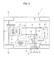
- FIG. 2 is a schematic diagram showing an internal structure of an electric vehicle constituting the electric charging system
- FIG. 3 is a schematic diagram showing an internal structure of an electric charger constituting the electric charging system
- FIG. 4 is a schematic diagram showing a state where a charging cable of the electric charger is connected to a charging port of the electric vehicle;
- FIGS. 5A to 5C are explanatory diagrams exemplifying failure states accompanied by electric leakage or heat
- FIG. 6 is a diagram showing an effect of filtering processing on a receiving voltage and a supply voltage.
- FIG. 7 is a diagram showing a change in the supply-side processed data and the receiving-side processed data in a pre-charging mode and a full-charging mode.
- FIG. 1 is a schematic diagram showing a case in which charging is preformed with an electric charging system 10 according to an embodiment of the present invention.
- FIG. 2 is a schematic diagram showing an internal structure of an electric vehicle 11 constituting the electric charging system 10 .
- FIG. 3 is a schematic diagram showing an internal structure of an electric charger 12 constituting the electric charging system 10 .
- the electric vehicle 11 is provided with a battery 13 as an electric storage device.
- a charging cable 14 of the electric charger 12 is connected to a charging port 13 of the electric vehicle 11 .
- the electric charger 12 charges the battery 13 to a predetermined state-of-charge (SOC), controlling a charging current and a charging voltage to be supplied to the electric vehicle 11 .
- SOC state-of-charge
- the electric vehicle 11 includes a motor-generator 20 or propulsion that is connected to drive wheels 22 via a drive axle 21 .
- the motor-generator 20 is connected to the battery 13 via an inverter 23 that bidirectionally converts DC power and AC power.
- the battery 13 and the inverter 23 are connected by current carrying lines 24 and 25 .
- Each of the current carrying lines 24 and 25 has a main relay 26 .
- the charging port 15 disposed at a side of the vehicle body is provided with a power receiving connector 27 .
- the power receiving connector 27 has a pair of power receiving terminals 27 a and 27 b .
- the power receiving terminal 27 a is connected to the current carrying line 24 , which is disposed on a positive electrode side, via a power receiving line 28 .
- the power receiving terminal 27 b is connected to the current carrying line 25 , which is disposed on a negative electrode side, via a power receiving line 29 .
- the electric vehicle 11 has a voltage sensor 30 that detects a voltage of the power receiving lines 28 and 29 , that is, a receiving voltage Vr, as well as a current sensor 31 that detects a current of the power receiving line 28 , that is, a receiving current Ir.
- the power receiving connector 27 has a signal terminal 27 c that is connected to a communication line 32 .
- the electric vehicle 11 includes a vehicle control unit 33 for integrally controlling the entire vehicle, a battery control unit 34 for controlling the battery 13 , and a motor control unit 35 for controlling the inverter 23 .
- the control units 33 to 35 are connected to each other via a communication line 36 .
- Each of the control units 33 to 35 is equipped with a CPU, a memory and the like.
- the electric charger 12 has a power converting unit 41 that converts AC power from an external power source 40 to DC power for charging.
- the power converting unit 41 includes a rectifier circuit, an electric transformer, a switching circuit and the like.
- a power supply connector 42 At an end of the charging cable 12 of the electric charger 14 is provided a power supply connector 42 that is attachable and detachable with respect to the power receiving connector 27 .
- the power supply connector 42 has a pair of power supply terminals 42 a ant 42 b that correspond to the power receiving terminals 27 a and 27 b of the power receiving connector 27 .
- Inc power supply terminal 42 a is connected to a positive electrode terminal 41 a of the power converting unit 41 via a power supply line 43 , while the power supply terminal 42 b is connected to a negative electrode terminal 41 b of the power converting unit 41 via a power supply line 44 .
- the electric charger 12 has a voltage sensor 45 that detects a voltage of the power supply lines 43 and 44 , that is, a supply voltage Vs, as well as a current sensor 46 that detects a current of the power supply line 43 , that is, a supply current Is.
- the power supply connector 42 has a signal terminal 42 c that is connected to a communication line 47 .
- the electric charger 12 includes a charging control unit 48 that is equipped with a CPU, a memory and the like. The charging control unit 48 transmits a control signal to the power converting unit 41 .
- FIG. 4 is a schematic diagram showing a state where the charging cable 14 of the electric charger 12 is connected to the charging port 15 of the electric vehicle 11 .
- connecting the power supply connector 42 of the charging cable 14 to the power receiving connector 27 of the charging port 15 causes a state where the power converting unit 41 and the battery 13 are connected to each other via the power supply lines 43 and 44 and the power receiving lines 28 and 29 .
- connecting the power supply connector 42 of the charging cable 14 to the power receiving connector 27 of the charging port 15 causes a state where the vehicle control unit 33 and the charging control unit 48 are connected to each other via the communication lines 32 and 47 .
- various pieces of battery information such as current instruction value, voltage instruction value, actual current value, actual voltage value, cell temperature and state of charge (SOC) are transmitted from the battery control unit 34 to the vehicle control unit 33 , and then transmitted from the battery control unit 33 to the battery control unit 48 via the communication lines 32 and 47 .
- the battery control unit 48 outputs a control signal to the power converting unit 41 so as to obtain a supply current Is corresponding to the current instruction value and a supply voltage Vs corresponding to the voltage instruction value, thereby charging the battery 13 to a predetermined SOC.
- the charging control unit 48 of the electric charger 12 may set the charging current and the like based on the SOC and the like.
- the charging control unit 48 compares the receiving voltage Vr and the supply voltage Vs during charging. If there is a difference therebetween that exceeds a predetermined amount, the charging control unit 48 determines that there occurs a breaking of the power supply line 43 or 44 , a connection failure of the connector 27 or 42 or the like, as shown in FIG. 5A , and halts charging. The charging control unit 48 also compares the receiving current Ir and the supply current Is.
- FIGS. 5A to 5C are explanatory diagrams exemplifying failure states accompanied by electric leakage or heat.
- the charging control unit 48 which serves as a determination unit of the present invention, compares the receiving current Vr and the supply current Vs as well as the receiving current Ir and the supply current Is in this manner so as to determine whether the conduction state between the electric charger 12 and the electric vehicle 11 is normal.
- FIG. 6 is a diagram showing an effect of filtering processing on the receiving voltage Vr and the supply voltage Vs. Note that filtering processing has similar affects on the receiving current Ir and the supply current Is. As shown FIG. 6 , when measured data detected by the voltage sensors 30 and 45 are subjected to filtering processing and then further processed to obtain determination data, a time lag occurs between the measured data and the determination data. The time lag due to filtering processing changes depending on the contents of the applied filtering process.
- a filtering process applied to the receiving voltage Vr or the receiving current Ir of the electric vehicle differs from a filtering process applied to the supply voltage Ds or the supply current Ir of the electric charger
- a time lag occurs between vehicle data (receiving-side processed data) Dr based on the receiving voltage Vr and the receiving current Ir and electric charger data (supply-side processed data) Ds based on the supply voltage Vs and the supply current Is. Therefore, in order to correctly determine an insulation failure or a breaking by comparing the vehicle data Dr and the electric charger Ds, it is necessary to determine a time lag and synchronize the vehicle data Dr and the electric charger Ds before comparing them.
- the charging control unit 48 serves as a receiving-side processing unit for calculating the vehicle data Dr as well as a supply-side processing unit for calculating the electric charger data Ds. Furthermore, the charging control unit 48 receives the receiving voltage Vr and the receiving current Ir detected at the electric vehicle from the vehicle control unit 33 via the communication line 32 and 47 .
- the charging control unit 48 which serves as a charging control unit of the present invention, performs the pre-charging mode before the full-charging mode for charging the battery 13 up to a first supply power.
- the pre-charging mode she battery 13 is charged up to a second supply power that is smaller than the first supply power.
- the charging control unit 48 firstly performs the pre-charging mode with a small supply power, and then the full-charging mode with a large supply power.
- the charging control unit 48 detects a time lag between the supply-side processed data and the receiving-side processed data, and synchronizes them in the full-charging mode based on the time lag.
- FIG. 7 is a diagram showing a change in the electric charger data Ds and the vehicle data Dr in the pre-charging mode and the full-charging mode.
- the charging control unit 48 which serves as a feature point assigning unit of the present invention, temporarily raises and drops the supply voltage Vs in the pre-charging mode using the power converting unit 41 . Since the power receiving lines 28 and 29 are connected to the power supply lines 43 and 44 , the receiving voltage Vr temporarily rises and falls in conjunction with the supply voltage Vs at a same timing, as shown in an enlarged portion of FIG. 7 .
- the supply voltage data Ds which is obtained by applying a filtering process to the supply voltage Vs is represented with a curve having an upward convex
- the vehicle data Dr which is obtained by applying a filtering process to the receiving voltage Vr is also represented with a curve having an upward convex.
- changing the supply voltage Vs assigns a feature point ⁇ 1 to the electric charger data Ds and a feature point ⁇ 2 to the vehicle data Dr.
- the supply voltage Vs is changed by, for example, artificially changing the supply current Is using the power converting unit 41 .
- the charging control unit 48 which servers as a data synchronizing unit of the present invention, measures a temporal distance between the feature points ⁇ 1 and ⁇ 2 to calculate a time lag T between the electric charger data Ds and the vehicle data Dr due to the filtering processing (for example, 0.5 seconds).
- the filtering processing for example, 0.5 seconds.
- the vehicle data Dr and the electric charger data Ds are synchronized based on the time lag T, whereby the electric charger data Ds ( ⁇ 1 ) and the vehicle data Dr ( ⁇ 2 ) can be compared.
- a difference ⁇ V 1 between the electric charger Ds and the vehicle data Dr can be properly recognized, and thus an insulation failure, a breaking and the like can be correctly determined.
- the receiving voltage Vs is changed in accordance with the artificially-changed supply voltage Vs.
- the present invention is not limited to this.
- the receiving voltage Vr may be artificially changed and the supply voltage Vs may be changed in accordance with the artificially-changed receiving voltage Vr.
- the receiving voltage Vr can be artificially changed by temporarily actuating an electric load installed in the electric vehicle 11 such as an electric heater.
- she supply voltage Vs is temporarily raised and dropped in the above explanation
- the present invention is not limited to this.
- the raised supply voltage Vs may be maintained.
- the supply voltage Vs and the receiving voltage vr are raised in the above explanation, the present invention is not limited to this.
- the supply voltage Vs and the receiving voltage Vr may be lowered.
- a feature point may be set at a point at where a predetermined voltage change amount or a voltage change speed is exceeded (or undershot) or a point at where a predetermined voltage value is exceeded (or undershot).
- an inflection point may be identified by changing the supply current instead of the supply voltage.
- the inflection point can be identified by monitoring a degree of rise in an operation where, for example, the supply current is raised to a predetermined current value in a relatively short time and then maintained.
- the case shown in FIG. 7 compares the electric charger data Ds which is obtained by applying a filtering process to the supply voltage Vs and the vehicle data Dr which is obtained by applying a filtering process to the receiving voltage Vr, but the present invention is not limited to this.
- the electric data Ds which is obtained by applying a filtering process to the supply current Is and the vehicle data Dr which is obtained by applying a filtering process to the receiving current Ir may be compared.
- a feature point may be assigned to the electric charger data Ds and the vehicle data Dr by altering the supply current Is and the receiving current Ir, or by altering the supply voltage Vs and the receiving voltage Vr.
- the vehicle data Dr which is obtained by applying a filtering process to the receiving voltage Vr or the receiving current Is at the electric vehicle and the electric charger data Ds which is obtained by applying a filtering process to the supply voltage Vs or the supply current Ir at the electric charger in order to determine an insulation failure, a breaking and the like.
- the present invention is not limited so this.
- a feature point may be assigned to the electric charger data Ds and the vehicle data Dr by altering the supply current Is and the receiving current Ir, or by altering the supply voltage Vs and the receiving voltage Vr.
- the charging control unit 48 in the electric charger 12 serves as the supply-side processing unit, receiving-side processing unit, feature point assigning unit, data synchronizing unit, determination unit and charging control unit.
- the present invention is not limited to this.
- the vehicle control unit 33 in the electric vehicle 11 may serves as the charging control unit 48 in the electric charger 12 serves as the supply-side processing unit, receiving-side processing unit, feature point assigning unit, data synchronizing unit, determination unit and charging control unit.
- the charging control unit 48 and the vehicle control unit 33 may share the functions of the charging control unit 48 in the electric charger 12 serves as the supply-side processing unit, receiving-side processing unit, feature point assigning unit, data synchronizing unit, determination unit and charging control unit.
- moving averaging and weighted moving averaging are referred to as a filtering process for calculating the vehicle data Dr and the electric charger data Ds, but the present invention is not limited to this.
- filtering may be applied in a hardware sense using an electric circuit or in a software sense using a program.
- the illustrated electric vehicle 11 is an electric vehicle which only has the motor-generator 20 for propulsion, but may be a hybrid-type electric vehicle that includes a motor-generator and an engine for propulsion.
- the battery 13 including a lithium-ion rechargeable battery, a nickel metal hydride rechargeable battery or the like is used as the electric storage device, but the present invention is not limited to this.
- the electric charger 12 in the above explanation is a conductive-type charger whose charging cable 14 is equipped with the power supply connector 42 of contact type, but the present invention is not limited to this.
- an inductive-type charger may be used whose charging cable is equipped with a power supply connector of non-contact type.
Abstract
Description
- The present application claims priority from Japanese Patent Application No. 2011-078294 filed on Mar. 31, 2011, the entire contents of which are hereby incorporated by reference.
- 1. Field of the Invention
- The present invention relates to an electric charging system that connects an electric charger and an electric vehicle via a charging cable and charges an electric storage device mounted on the electric vehicle.
- 2. Description of the Related Art
- In recent years, electric vehicles that are equipped with an electric motor for propulsion have been under development. The electric vehicle is equipped with an electric storage device such as battery. Upon charging the electric storage device, a charging cable extending from an electric charger is connected to a charging port of the electric vehicle (see, for example, Japanese Unexamined Patent Application Publication No. 2009-83670). Furthermore, in the field of hybrid electric vehicles that are equipped with an engine and an electric motor for propulsion, so called a plug-in type vehicle is under development whose electric storage device can be charged with an electric charger.
- Since supply power from the electric charger to the electric vehicle has a high voltage and a high capacity, it is necessary to monitor an insulation failure, a breaking of the charging cable and the like in order to prevent electric leakage or the like and secure safety upon charging. Examples of the monitoring method of the insulation failure and the like includes the comparison of a supply voltage of the electric charger and a receiving voltage of the electric vehicle and the comparison of a supply current of the electric charger and a receiving current of the electric vehicle. If there is a large difference between the supply voltage and the receiving voltage or between the supply current and the receiving current, there is a possibility that electric power flows into a system other than the electric vehicle, and thus it is determined that there occurs an insulation failure or the like.
- Upon the detection of an insulation failure or the like, voltage data and current data output by a voltage sensor and a current sensor are used. When these data are used, it is common to eliminate noise effects by applying a filtering process such moving averaging and weighted moving averaging. However, there is a time lag in the filtered voltage data or the filtered current data, a simple comparison of the voltage data or the like between the electric charger and the electric vehicle may cause an erroneous determination of an insulation failure or the like. In other words, if there is a time lag between the electric charger and the electric vehicle, but the data thereof are not synchronized, there may be a big difference in the data between the electric charger and the electric vehicle although no insulation failure or the like occurs, or a difference may not be observed in the data between the electric charger and the electric vehicle although there occurs an insulation failure or the like.
- The present invention aims to correctly determine whether or not a conduction state between an electric charger and an electric vehicle is normal.
- An aspect or the present invention provides an electric charging system that connects an electric charger and an electric vehicle via a charging cable and charges an electric storage device mounted on the electric vehicle, the electric charging system including: a supply-side processing unit for calculating supply-side processed data by applying a predetermined filtering process to a supply voltage, a supply current or a supply power in the electric charger; a receiving-side processing unit for calculating receiving-side processed data by applying a predetermined filtering process to a receiving voltage, a receiving current or a receiving power in the electric vehicle; a feature point assigning unit for assigning a feature point to the supply-side processed data and the receiving-side processed data by altering at least any one of the supply voltage, the supply current, the receiving voltage and the receiving current; a data synchronizing unit for synchronizing the supply-side processed data and the receiving-side processed data based on the feature point of the supply-side processed data and the receiving-side processed data; and a determination unit for determining whether or not a conduction state between the electric charger and the electric vehicle is normal.
- Preferably, the filtering process used by the supply-side processing unit and the filtering process used by the receiving-side processing unit should be different.
- Preferably, the electric charging system should include a charging control unit that has a full-charging mode for charging the electric storage device up to a first supply power and a pre-charging mode for charging the electric storage device up to a second supply power that is smaller than the first supply power, and the feature point assigning unit should assign a feature point to the supply-side processed data and the receiving-side processed data in the pre-charging mode performed in prior to the full-charging mode.
- Preferably, the feature point assigning unit should assign the feature point to the supply-side processed data and the receiving-side processed data by altering the supply current or the receiving current.
- Preferably, the data synchronizing unit should calculate a time lag between the supply-side processed data and the receiving-side processed data based on the feature point and synchronize the supply-side processed data and the receiving-side processed data based on the time lag.
- Preferably, the electric charger should be provided with the supply-side processing unit, the receiving-side processing unit, the feature point assigning unit, the data synchronizing unit and the determination unit.
- Preferably, the receiving voltage, the receiving current or the receiving power in the electric vehicle should be sent to the receiving-side processing unit via a communication line in the charging cable.
- According to the present invention, the feature point is assigned to the supply-side processed data and the receiving-side processed data by altering at least the one of the supply voltage, the supply current and the receiving voltage, whereby the supply-side processed data and the receiving-side processed data can be synchronized based on the feature point. As a result, is possible to properly compare the supply-side processed data and the receiving side processed data and correctly determine whether or not the conduction state between the electric charger and the electric vehicle is normal.
-
FIG. 1 is a schematic diagram showing a case in which charging is preformed with an electric charging system according to an embodiment of the present invention; -
FIG. 2 is a schematic diagram showing an internal structure of an electric vehicle constituting the electric charging system; -
FIG. 3 is a schematic diagram showing an internal structure of an electric charger constituting the electric charging system; -
FIG. 4 is a schematic diagram showing a state where a charging cable of the electric charger is connected to a charging port of the electric vehicle; -
FIGS. 5A to 5C are explanatory diagrams exemplifying failure states accompanied by electric leakage or heat; -
FIG. 6 is a diagram showing an effect of filtering processing on a receiving voltage and a supply voltage; and -
FIG. 7 is a diagram showing a change in the supply-side processed data and the receiving-side processed data in a pre-charging mode and a full-charging mode. - An embodiment of the present invention will hereunder be described with reference to the drawings.
FIG. 1 is a schematic diagram showing a case in which charging is preformed with anelectric charging system 10 according to an embodiment of the present invention.FIG. 2 is a schematic diagram showing an internal structure of anelectric vehicle 11 constituting theelectric charging system 10.FIG. 3 is a schematic diagram showing an internal structure of anelectric charger 12 constituting theelectric charging system 10. As shown inFIG. 1 theelectric vehicle 11 is provided with abattery 13 as an electric storage device. When thebattery 13 is charged, acharging cable 14 of theelectric charger 12 is connected to acharging port 13 of theelectric vehicle 11. Theelectric charger 12 charges thebattery 13 to a predetermined state-of-charge (SOC), controlling a charging current and a charging voltage to be supplied to theelectric vehicle 11. - As shown in
FIG. 2 , theelectric vehicle 11 includes a motor-generator 20 or propulsion that is connected to drivewheels 22 via adrive axle 21. The motor-generator 20 is connected to thebattery 13 via aninverter 23 that bidirectionally converts DC power and AC power. Thebattery 13 and theinverter 23 are connected bycurrent carrying lines current carrying lines main relay 26. Thecharging port 15 disposed at a side of the vehicle body is provided with apower receiving connector 27. Thepower receiving connector 27 has a pair ofpower receiving terminals power receiving terminal 27 a is connected to thecurrent carrying line 24, which is disposed on a positive electrode side, via apower receiving line 28. Thepower receiving terminal 27 b is connected to thecurrent carrying line 25, which is disposed on a negative electrode side, via apower receiving line 29. Theelectric vehicle 11 has avoltage sensor 30 that detects a voltage of thepower receiving lines current sensor 31 that detects a current of the power receivingline 28, that is, a receiving current Ir. Thepower receiving connector 27 has asignal terminal 27 c that is connected to acommunication line 32. Theelectric vehicle 11 includes avehicle control unit 33 for integrally controlling the entire vehicle, abattery control unit 34 for controlling thebattery 13, and amotor control unit 35 for controlling theinverter 23. Thecontrol units 33 to 35 are connected to each other via acommunication line 36. Each of thecontrol units 33 to 35 is equipped with a CPU, a memory and the like. - As shown in
FIG. 3 , theelectric charger 12 has apower converting unit 41 that converts AC power from anexternal power source 40 to DC power for charging. Thepower converting unit 41 includes a rectifier circuit, an electric transformer, a switching circuit and the like. At an end of thecharging cable 12 of theelectric charger 14 is provided apower supply connector 42 that is attachable and detachable with respect to thepower receiving connector 27. Thepower supply connector 42 has a pair ofpower supply terminals 42 aant 42 b that correspond to thepower receiving terminals power supply terminal 42 a is connected to apositive electrode terminal 41 a of thepower converting unit 41 via apower supply line 43, while thepower supply terminal 42 b is connected to anegative electrode terminal 41 b of thepower converting unit 41 via apower supply line 44. Theelectric charger 12 has avoltage sensor 45 that detects a voltage of thepower supply lines current sensor 46 that detects a current of thepower supply line 43, that is, a supply current Is. Thepower supply connector 42 has asignal terminal 42 c that is connected to acommunication line 47. Theelectric charger 12 includes a chargingcontrol unit 48 that is equipped with a CPU, a memory and the like. The chargingcontrol unit 48 transmits a control signal to thepower converting unit 41. -
FIG. 4 is a schematic diagram showing a state where the chargingcable 14 of theelectric charger 12 is connected to the chargingport 15 of theelectric vehicle 11. As shown inFIG. 4 , connecting thepower supply connector 42 of the chargingcable 14 to thepower receiving connector 27 of the chargingport 15 causes a state where thepower converting unit 41 and thebattery 13 are connected to each other via thepower supply lines power receiving lines power supply connector 42 of the chargingcable 14 to thepower receiving connector 27 of the chargingport 15 causes a state where thevehicle control unit 33 and the chargingcontrol unit 48 are connected to each other via thecommunication lines electric charger 12 and theelectric vehicle 11 are connected in this manner, various pieces of battery information such as current instruction value, voltage instruction value, actual current value, actual voltage value, cell temperature and state of charge (SOC) are transmitted from thebattery control unit 34 to thevehicle control unit 33, and then transmitted from thebattery control unit 33 to thebattery control unit 48 via thecommunication lines battery control unit 48 outputs a control signal to thepower converting unit 41 so as to obtain a supply current Is corresponding to the current instruction value and a supply voltage Vs corresponding to the voltage instruction value, thereby charging thebattery 13 to a predetermined SOC. While theelectric vehicle 11 instructs theelectric charger 12 on the charging current and the like in the above explanation, the present invention is not limited to this. Alternatively, the chargingcontrol unit 48 of theelectric charger 12 may set the charging current and the like based on the SOC and the like. - Since the
electric charger 12 provides theelectric vehicle 11 with a high-voltage and high-capacity power (for example, DC 400 V, 100 A) during charging in the above manner, it is important to prevent an electric leakage, heat and the like by monitoring an insulation failure, a breaking of thepower supply lines control unit 48 compares the receiving voltage Vr and the supply voltage Vs during charging. If there is a difference therebetween that exceeds a predetermined amount, the chargingcontrol unit 48 determines that there occurs a breaking of thepower supply line connector FIG. 5A , and halts charging. The chargingcontrol unit 48 also compares the receiving current Ir and the supply current Is. If there is a difference therebetween that exceeds a predetermined amount, the chargingcontrol unit 48 determines that there occurs a short circuit or an earth fault between thepower supply line FIGS. 5B and 5C , and halts charging.FIGS. 5A to 5C are explanatory diagrams exemplifying failure states accompanied by electric leakage or heat. The chargingcontrol unit 48, which serves as a determination unit of the present invention, compares the receiving current Vr and the supply current Vs as well as the receiving current Ir and the supply current Is in this manner so as to determine whether the conduction state between theelectric charger 12 and theelectric vehicle 11 is normal. However, in order to use the receiving current Vr, the supply current Vs, the receiving current Ir and the supply current Is detected by thevoltage sensors current sensors -
FIG. 6 is a diagram showing an effect of filtering processing on the receiving voltage Vr and the supply voltage Vs. Note that filtering processing has similar affects on the receiving current Ir and the supply current Is. As shownFIG. 6 , when measured data detected by thevoltage sensors control unit 48 serves as a receiving-side processing unit for calculating the vehicle data Dr as well as a supply-side processing unit for calculating the electric charger data Ds. Furthermore, the chargingcontrol unit 48 receives the receiving voltage Vr and the receiving current Ir detected at the electric vehicle from thevehicle control unit 33 via thecommunication line - The charging
control unit 48, which serves as a charging control unit of the present invention, performs the pre-charging mode before the full-charging mode for charging thebattery 13 up to a first supply power. In the pre-charging mode, shebattery 13 is charged up to a second supply power that is smaller than the first supply power. In other words, the chargingcontrol unit 48 firstly performs the pre-charging mode with a small supply power, and then the full-charging mode with a large supply power. In the pre-charging mode, the chargingcontrol unit 48 detects a time lag between the supply-side processed data and the receiving-side processed data, and synchronizes them in the full-charging mode based on the time lag. -
FIG. 7 is a diagram showing a change in the electric charger data Ds and the vehicle data Dr in the pre-charging mode and the full-charging mode. As shown inFIG. 7 , the chargingcontrol unit 48, which serves as a feature point assigning unit of the present invention, temporarily raises and drops the supply voltage Vs in the pre-charging mode using thepower converting unit 41. Since thepower receiving lines power supply lines FIG. 7 . Accordingly, the supply voltage data Ds which is obtained by applying a filtering process to the supply voltage Vs is represented with a curve having an upward convex, while the vehicle data Dr which is obtained by applying a filtering process to the receiving voltage Vr is also represented with a curve having an upward convex. In other words, changing the supply voltage Vs assigns a feature point α1 to the electric charger data Ds and a feature point α2 to the vehicle data Dr. The supply voltage Vs is changed by, for example, artificially changing the supply current Is using thepower converting unit 41. - Since the feature point α1 assigned to the electric charger data Ds and the feature point α2 assigned so the vehicle data Dr has a same timing, as described above, the charging
control unit 48, which servers as a data synchronizing unit of the present invention, measures a temporal distance between the feature points α1 and α2 to calculate a time lag T between the electric charger data Ds and the vehicle data Dr due to the filtering processing (for example, 0.5 seconds). Upon the determination of an insulation failure, a breaking or the like in the full-charging mode, the electric charger data Ds (β1) and the vehicle data Dr (β2) are compared with the time lag T being taken into account. If the electric charger Ds (β1) and the vehicle data Dr (β3) that are output at a same time point, an erroneous determination is made that there is a large difference of ΔV2 between the electric charger data Ds and the vehicle data Dr. Thus, the vehicle data Dr and the electric charger data Ds are synchronized based on the time lag T, whereby the electric charger data Ds (β1) and the vehicle data Dr (β2) can be compared. As a result, a difference ΔV1 between the electric charger Ds and the vehicle data Dr can be properly recognized, and thus an insulation failure, a breaking and the like can be correctly determined. - In the above explanation, the receiving voltage Vs is changed in accordance with the artificially-changed supply voltage Vs. However, the present invention is not limited to this. Alternatively, the receiving voltage Vr may be artificially changed and the supply voltage Vs may be changed in accordance with the artificially-changed receiving voltage Vr. In this case, the receiving voltage Vr can be artificially changed by temporarily actuating an electric load installed in the
electric vehicle 11 such as an electric heater. Further, while she supply voltage Vs is temporarily raised and dropped in the above explanation, the present invention is not limited to this. Alternatively, the raised supply voltage Vs may be maintained. Furthermore, the supply voltage Vs and the receiving voltage vr are raised in the above explanation, the present invention is not limited to this. Alternatively, the supply voltage Vs and the receiving voltage Vr may be lowered. Furthermore, while the above description uses inflection points of the electric charger data Ds and the vehicle data Dr as the feature points α1 and α2, the present invention is non limited to this. Alternatively, a feature point may be set at a point at where a predetermined voltage change amount or a voltage change speed is exceeded (or undershot) or a point at where a predetermined voltage value is exceeded (or undershot). Furthermore, an inflection point may be identified by changing the supply current instead of the supply voltage. For example, the inflection point can be identified by monitoring a degree of rise in an operation where, for example, the supply current is raised to a predetermined current value in a relatively short time and then maintained. - The case shown in
FIG. 7 compares the electric charger data Ds which is obtained by applying a filtering process to the supply voltage Vs and the vehicle data Dr which is obtained by applying a filtering process to the receiving voltage Vr, but the present invention is not limited to this. Alternatively, as described above, the electric data Ds which is obtained by applying a filtering process to the supply current Is and the vehicle data Dr which is obtained by applying a filtering process to the receiving current Ir may be compared. In this case, a feature point may be assigned to the electric charger data Ds and the vehicle data Dr by altering the supply current Is and the receiving current Ir, or by altering the supply voltage Vs and the receiving voltage Vr. Furthermore, in the above explanation, the vehicle data Dr which is obtained by applying a filtering process to the receiving voltage Vr or the receiving current Is at the electric vehicle and the electric charger data Ds which is obtained by applying a filtering process to the supply voltage Vs or the supply current Ir at the electric charger in order to determine an insulation failure, a breaking and the like. However, the present invention is not limited so this. Alternatively, the vehicle data Dr that is obtained by applying a filtering process to a receiving power Wr at the electric vehicle (Wr=Ir×Vr) and the electric charger data Ds that is obtained by applying a filtering process to a supply power Ws at the electric charger (Ws=Is×Vs). In this case, again, a feature point may be assigned to the electric charger data Ds and the vehicle data Dr by altering the supply current Is and the receiving current Ir, or by altering the supply voltage Vs and the receiving voltage Vr. - The present invention is not limited to the aforementioned embodiment, and permits various modifications and alterations within the technical scope of the invention. In the above embodiment, the charging
control unit 48 in theelectric charger 12 serves as the supply-side processing unit, receiving-side processing unit, feature point assigning unit, data synchronizing unit, determination unit and charging control unit. However, the present invention is not limited to this. For example, thevehicle control unit 33 in theelectric vehicle 11 may serves as the chargingcontrol unit 48 in theelectric charger 12 serves as the supply-side processing unit, receiving-side processing unit, feature point assigning unit, data synchronizing unit, determination unit and charging control unit. Further alternatively, the chargingcontrol unit 48 and thevehicle control unit 33 may share the functions of the chargingcontrol unit 48 in theelectric charger 12 serves as the supply-side processing unit, receiving-side processing unit, feature point assigning unit, data synchronizing unit, determination unit and charging control unit. - Further, moving averaging and weighted moving averaging are referred to as a filtering process for calculating the vehicle data Dr and the electric charger data Ds, but the present invention is not limited to this. Besides, filtering may be applied in a hardware sense using an electric circuit or in a software sense using a program. Furthermore, the illustrated
electric vehicle 11 is an electric vehicle which only has the motor-generator 20 for propulsion, but may be a hybrid-type electric vehicle that includes a motor-generator and an engine for propulsion. Further, thebattery 13 including a lithium-ion rechargeable battery, a nickel metal hydride rechargeable battery or the like is used as the electric storage device, but the present invention is not limited to this. Alternatively, a capacitor such as a lithium-ion capacitor and an electric double layer capacitor may be used as the electricity storage device. Furthermore, theelectric charger 12 in the above explanation is a conductive-type charger whose chargingcable 14 is equipped with thepower supply connector 42 of contact type, but the present invention is not limited to this. Alternatively, an inductive-type charger may be used whose charging cable is equipped with a power supply connector of non-contact type.
Claims (8)
Applications Claiming Priority (2)
| Application Number | Priority Date | Filing Date | Title |
|---|---|---|---|
| JP2011078294A JP5575040B2 (en) | 2011-03-31 | 2011-03-31 | Charging system |
| JP2011-078294 | 2011-03-31 |
Publications (2)
| Publication Number | Publication Date |
|---|---|
| US20120249069A1 true US20120249069A1 (en) | 2012-10-04 |
| US8796991B2 US8796991B2 (en) | 2014-08-05 |
Family
ID=46845215
Family Applications (1)
| Application Number | Title | Priority Date | Filing Date |
|---|---|---|---|
| US13/426,707 Active 2033-01-18 US8796991B2 (en) | 2011-03-31 | 2012-03-22 | Electric charging system |
Country Status (4)
| Country | Link |
|---|---|
| US (1) | US8796991B2 (en) |
| JP (1) | JP5575040B2 (en) |
| CN (1) | CN102729833B (en) |
| DE (1) | DE102012102587A1 (en) |
Cited By (29)
| Publication number | Priority date | Publication date | Assignee | Title |
|---|---|---|---|---|
| US20130127413A1 (en) * | 2011-11-18 | 2013-05-23 | Fuji Jukogyo Kabushiki Kaisha | Electric charging system and electric vehicle |
| US20130158782A1 (en) * | 2007-07-17 | 2013-06-20 | Midtronics, Inc. | Battery tester for electric vehicle |
| US20150160281A1 (en) * | 2012-07-05 | 2015-06-11 | Audi Ag | Diagnostic device for checking a control signal line |
| US20160124046A1 (en) * | 2014-11-04 | 2016-05-05 | Hyundai Motor Company | Method for detecting interlock failure of connector in eco-friendly vechicle |
| US9496720B2 (en) | 2004-08-20 | 2016-11-15 | Midtronics, Inc. | System for automatically gathering battery information |
| US9588185B2 (en) | 2010-02-25 | 2017-03-07 | Keith S. Champlin | Method and apparatus for detecting cell deterioration in an electrochemical cell or battery |
| US20170125993A1 (en) * | 2014-08-07 | 2017-05-04 | Bayerische Motoren Werke Aktiengesellschaft | Vehicle with a Storage Device That Can be Recharged by Way of a Charging Cable and an External Power Supply |
| US9851411B2 (en) | 2012-06-28 | 2017-12-26 | Keith S. Champlin | Suppressing HF cable oscillations during dynamic measurements of cells and batteries |
| US9923289B2 (en) | 2014-01-16 | 2018-03-20 | Midtronics, Inc. | Battery clamp with endoskeleton design |
| US9966676B2 (en) | 2015-09-28 | 2018-05-08 | Midtronics, Inc. | Kelvin connector adapter for storage battery |
| US10046649B2 (en) | 2012-06-28 | 2018-08-14 | Midtronics, Inc. | Hybrid and electric vehicle battery pack maintenance device |
| US10222397B2 (en) | 2014-09-26 | 2019-03-05 | Midtronics, Inc. | Cable connector for electronic battery tester |
| US10317468B2 (en) | 2015-01-26 | 2019-06-11 | Midtronics, Inc. | Alternator tester |
| US10429449B2 (en) | 2011-11-10 | 2019-10-01 | Midtronics, Inc. | Battery pack tester |
| US10473555B2 (en) | 2014-07-14 | 2019-11-12 | Midtronics, Inc. | Automotive maintenance system |
| US10569666B1 (en) * | 2018-10-15 | 2020-02-25 | Hyundai Motor Company | Vehicle and method for controlling the same |
| US10608353B2 (en) | 2016-06-28 | 2020-03-31 | Midtronics, Inc. | Battery clamp |
| US10843574B2 (en) | 2013-12-12 | 2020-11-24 | Midtronics, Inc. | Calibration and programming of in-vehicle battery sensors |
| US11054480B2 (en) | 2016-10-25 | 2021-07-06 | Midtronics, Inc. | Electrical load for electronic battery tester and electronic battery tester including such electrical load |
| US11325479B2 (en) | 2012-06-28 | 2022-05-10 | Midtronics, Inc. | Hybrid and electric vehicle battery maintenance device |
| US11474153B2 (en) | 2019-11-12 | 2022-10-18 | Midtronics, Inc. | Battery pack maintenance system |
| US11486930B2 (en) | 2020-01-23 | 2022-11-01 | Midtronics, Inc. | Electronic battery tester with battery clamp storage holsters |
| US11513160B2 (en) | 2018-11-29 | 2022-11-29 | Midtronics, Inc. | Vehicle battery maintenance device |
| US11545839B2 (en) | 2019-11-05 | 2023-01-03 | Midtronics, Inc. | System for charging a series of connected batteries |
| US11566972B2 (en) | 2019-07-31 | 2023-01-31 | Midtronics, Inc. | Tire tread gauge using visual indicator |
| US11650259B2 (en) | 2010-06-03 | 2023-05-16 | Midtronics, Inc. | Battery pack maintenance for electric vehicle |
| US11668779B2 (en) | 2019-11-11 | 2023-06-06 | Midtronics, Inc. | Hybrid and electric vehicle battery pack maintenance device |
| US11740294B2 (en) | 2010-06-03 | 2023-08-29 | Midtronics, Inc. | High use battery pack maintenance |
| US11973202B2 (en) | 2020-12-29 | 2024-04-30 | Midtronics, Inc. | Intelligent module interface for battery maintenance device |
Families Citing this family (6)
| Publication number | Priority date | Publication date | Assignee | Title |
|---|---|---|---|---|
| PT3220506T (en) | 2014-11-11 | 2020-05-06 | Guangdong Oppo Mobile Telecommunications Corp Ltd | Communication method, power adaptor and terminal |
| EP3214726B1 (en) | 2016-01-05 | 2018-11-21 | Guangdong Oppo Mobile Telecommunications Corp., Ltd. | Rapid charging method, mobile terminal and adapter |
| DE102018101704A1 (en) * | 2018-01-25 | 2019-07-25 | Volkswagen Aktiengesellschaft | Power supply device |
| US11752958B2 (en) | 2020-05-28 | 2023-09-12 | Transportation Ip Holdings, Llc | Systems and methods for providing power to sensors |
| WO2023136338A1 (en) * | 2022-01-14 | 2023-07-20 | 日置電機株式会社 | Measuring system, electricity storage apparatus, and measuring apparatus |
| US11904723B1 (en) * | 2023-06-28 | 2024-02-20 | Rivian Ip Holdings, Llc | Vehicle to external load charger |
Citations (3)
| Publication number | Priority date | Publication date | Assignee | Title |
|---|---|---|---|---|
| US20070085494A1 (en) * | 2005-10-19 | 2007-04-19 | Koito Manufacturing Co., Ltd. | Lighting controller for lighting device for vehicle |
| US20090030712A1 (en) * | 2007-07-26 | 2009-01-29 | Bradley D. Bogolea | System and method for transferring electrical power between grid and vehicle |
| US20100185357A1 (en) * | 2008-01-25 | 2010-07-22 | Kyushu Electric Power Co., Inc. | Electrically-driven apparatus charging system and method |
Family Cites Families (9)
| Publication number | Priority date | Publication date | Assignee | Title |
|---|---|---|---|---|
| JPH05191929A (en) * | 1992-01-14 | 1993-07-30 | Fujitsu Ltd | Detection circuit for disconnection of battery connecting line |
| JP3214045B2 (en) * | 1992-03-27 | 2001-10-02 | 株式会社明電舎 | Charging device |
| JPH06245325A (en) * | 1993-02-22 | 1994-09-02 | Fujitsu Denso Ltd | Communication control system for electric automobile |
| JPH07240705A (en) * | 1994-02-28 | 1995-09-12 | Clarion Co Ltd | Electric automobile charging system |
| JP4930310B2 (en) | 2007-09-28 | 2012-05-16 | 三菱自動車工業株式会社 | Electric car |
| JP5332629B2 (en) * | 2009-01-14 | 2013-11-06 | トヨタ自動車株式会社 | Electric vehicle charging system |
| JP2010239773A (en) * | 2009-03-31 | 2010-10-21 | Tokyo Electric Power Co Inc:The | Charger, electric vehicle and method for detecting ground fault-short circuit in charging system |
| JP2011015581A (en) * | 2009-07-03 | 2011-01-20 | San'eisha Mfg Co Ltd | Device for detecting deterioration of quick charger for electric vehicle |
| JP5443094B2 (en) * | 2009-08-11 | 2014-03-19 | 株式会社 ハセテック | Electric vehicle quick charger charging cable insulation test equipment |
-
2011
- 2011-03-31 JP JP2011078294A patent/JP5575040B2/en active Active
-
2012
- 2012-03-22 US US13/426,707 patent/US8796991B2/en active Active
- 2012-03-26 DE DE102012102587A patent/DE102012102587A1/en active Pending
- 2012-03-30 CN CN201210091123.1A patent/CN102729833B/en active Active
Patent Citations (3)
| Publication number | Priority date | Publication date | Assignee | Title |
|---|---|---|---|---|
| US20070085494A1 (en) * | 2005-10-19 | 2007-04-19 | Koito Manufacturing Co., Ltd. | Lighting controller for lighting device for vehicle |
| US20090030712A1 (en) * | 2007-07-26 | 2009-01-29 | Bradley D. Bogolea | System and method for transferring electrical power between grid and vehicle |
| US20100185357A1 (en) * | 2008-01-25 | 2010-07-22 | Kyushu Electric Power Co., Inc. | Electrically-driven apparatus charging system and method |
Cited By (38)
| Publication number | Priority date | Publication date | Assignee | Title |
|---|---|---|---|---|
| US9496720B2 (en) | 2004-08-20 | 2016-11-15 | Midtronics, Inc. | System for automatically gathering battery information |
| US9335362B2 (en) * | 2007-07-17 | 2016-05-10 | Midtronics, Inc. | Battery tester for electric vehicle |
| US20130158782A1 (en) * | 2007-07-17 | 2013-06-20 | Midtronics, Inc. | Battery tester for electric vehicle |
| US9588185B2 (en) | 2010-02-25 | 2017-03-07 | Keith S. Champlin | Method and apparatus for detecting cell deterioration in an electrochemical cell or battery |
| US11740294B2 (en) | 2010-06-03 | 2023-08-29 | Midtronics, Inc. | High use battery pack maintenance |
| US11650259B2 (en) | 2010-06-03 | 2023-05-16 | Midtronics, Inc. | Battery pack maintenance for electric vehicle |
| US10429449B2 (en) | 2011-11-10 | 2019-10-01 | Midtronics, Inc. | Battery pack tester |
| US9102238B2 (en) * | 2011-11-18 | 2015-08-11 | Fuji Jukogyo Kabushiki Kaisha | Fail state determination apparatus for electric vehicle charging system |
| US20130127413A1 (en) * | 2011-11-18 | 2013-05-23 | Fuji Jukogyo Kabushiki Kaisha | Electric charging system and electric vehicle |
| US11325479B2 (en) | 2012-06-28 | 2022-05-10 | Midtronics, Inc. | Hybrid and electric vehicle battery maintenance device |
| US9851411B2 (en) | 2012-06-28 | 2017-12-26 | Keith S. Champlin | Suppressing HF cable oscillations during dynamic measurements of cells and batteries |
| US10046649B2 (en) | 2012-06-28 | 2018-08-14 | Midtronics, Inc. | Hybrid and electric vehicle battery pack maintenance device |
| US11548404B2 (en) | 2012-06-28 | 2023-01-10 | Midtronics, Inc. | Hybrid and electric vehicle battery pack maintenance device |
| US11926224B2 (en) | 2012-06-28 | 2024-03-12 | Midtronics, Inc. | Hybrid and electric vehicle battery pack maintenance device |
| US10168373B2 (en) * | 2012-07-05 | 2019-01-01 | Audi Ag | Diagnostic device for checking a control signal line |
| US20150160281A1 (en) * | 2012-07-05 | 2015-06-11 | Audi Ag | Diagnostic device for checking a control signal line |
| US10843574B2 (en) | 2013-12-12 | 2020-11-24 | Midtronics, Inc. | Calibration and programming of in-vehicle battery sensors |
| US9923289B2 (en) | 2014-01-16 | 2018-03-20 | Midtronics, Inc. | Battery clamp with endoskeleton design |
| US10473555B2 (en) | 2014-07-14 | 2019-11-12 | Midtronics, Inc. | Automotive maintenance system |
| US10720766B2 (en) * | 2014-08-07 | 2020-07-21 | Bayerische Motoren Werke Aktiengesellschaft | Vehicle with a storage device that can be recharged by way of a charging cable and an external power supply |
| US20170125993A1 (en) * | 2014-08-07 | 2017-05-04 | Bayerische Motoren Werke Aktiengesellschaft | Vehicle with a Storage Device That Can be Recharged by Way of a Charging Cable and an External Power Supply |
| US10222397B2 (en) | 2014-09-26 | 2019-03-05 | Midtronics, Inc. | Cable connector for electronic battery tester |
| US10962423B2 (en) * | 2014-11-04 | 2021-03-30 | Hyundai Motor Company | Method for detecting interlock failure of connector in eco-friendly vehicle |
| US20160124046A1 (en) * | 2014-11-04 | 2016-05-05 | Hyundai Motor Company | Method for detecting interlock failure of connector in eco-friendly vechicle |
| US10317468B2 (en) | 2015-01-26 | 2019-06-11 | Midtronics, Inc. | Alternator tester |
| US9966676B2 (en) | 2015-09-28 | 2018-05-08 | Midtronics, Inc. | Kelvin connector adapter for storage battery |
| US10608353B2 (en) | 2016-06-28 | 2020-03-31 | Midtronics, Inc. | Battery clamp |
| US11054480B2 (en) | 2016-10-25 | 2021-07-06 | Midtronics, Inc. | Electrical load for electronic battery tester and electronic battery tester including such electrical load |
| US10569666B1 (en) * | 2018-10-15 | 2020-02-25 | Hyundai Motor Company | Vehicle and method for controlling the same |
| KR102543313B1 (en) | 2018-10-15 | 2023-06-16 | 현대자동차주식회사 | Vehicle and controlling method for the same |
| KR20200042130A (en) * | 2018-10-15 | 2020-04-23 | 현대자동차주식회사 | Vehicle and controlling method for the same |
| US11513160B2 (en) | 2018-11-29 | 2022-11-29 | Midtronics, Inc. | Vehicle battery maintenance device |
| US11566972B2 (en) | 2019-07-31 | 2023-01-31 | Midtronics, Inc. | Tire tread gauge using visual indicator |
| US11545839B2 (en) | 2019-11-05 | 2023-01-03 | Midtronics, Inc. | System for charging a series of connected batteries |
| US11668779B2 (en) | 2019-11-11 | 2023-06-06 | Midtronics, Inc. | Hybrid and electric vehicle battery pack maintenance device |
| US11474153B2 (en) | 2019-11-12 | 2022-10-18 | Midtronics, Inc. | Battery pack maintenance system |
| US11486930B2 (en) | 2020-01-23 | 2022-11-01 | Midtronics, Inc. | Electronic battery tester with battery clamp storage holsters |
| US11973202B2 (en) | 2020-12-29 | 2024-04-30 | Midtronics, Inc. | Intelligent module interface for battery maintenance device |
Also Published As
| Publication number | Publication date |
|---|---|
| DE102012102587A1 (en) | 2012-10-04 |
| CN102729833B (en) | 2014-09-03 |
| JP2012211860A (en) | 2012-11-01 |
| JP5575040B2 (en) | 2014-08-20 |
| US8796991B2 (en) | 2014-08-05 |
| CN102729833A (en) | 2012-10-17 |
Similar Documents
| Publication | Publication Date | Title |
|---|---|---|
| US8796991B2 (en) | Electric charging system | |
| US8860368B2 (en) | Electric charging system and electric vehicle | |
| US10189360B2 (en) | Electric charging system | |
| CN107599857B (en) | Pure electric vehicle charging system and charging method based on lithium battery | |
| US8786253B2 (en) | Electric charging system and electric charger | |
| JP5637339B1 (en) | Electric power supply device using electric vehicle | |
| US9929674B2 (en) | Power supply system for vehicle | |
| EP2690741B1 (en) | Adapter, and vehicle and method for supplying power using same | |
| US8660732B2 (en) | Vehicle with external charging | |
| US20110234159A1 (en) | Charging device | |
| US20130088198A1 (en) | Electric charging system and electric charging method | |
| US11135935B2 (en) | Vehicle charging system | |
| US11427084B2 (en) | Vehicle | |
| US11198372B2 (en) | Vehicle and sticking diagnosis method | |
| JP2012080712A (en) | Vehicle charging apparatus | |
| EP4088964A1 (en) | Charging controller and vehicle | |
| US20230095211A1 (en) | Vehicle and charging method of vehicle | |
| JP5975925B2 (en) | Battery control device, power storage device | |
| US11813948B2 (en) | Vehicle and vehicle control method including controlling charging and discharging for protecting a power line |
Legal Events
| Date | Code | Title | Description |
|---|---|---|---|
| AS | Assignment |
Owner name: FUJI JUKOGYO KABUSHIKI KAISHA, JAPAN Free format text: ASSIGNMENT OF ASSIGNORS INTEREST;ASSIGNOR:OHTOMO, YOSUKE;REEL/FRAME:027907/0287 Effective date: 20120113 |
|
| STCF | Information on status: patent grant |
Free format text: PATENTED CASE |
|
| AS | Assignment |
Owner name: FUJI JUKOGYO KABUSHIKI KAISHA, JAPAN Free format text: CHANGE OF ADDRESS;ASSIGNOR:FUJI JUKOGYO KABUSHIKI KAISHA;REEL/FRAME:034215/0580 Effective date: 20140818 |
|
| FEPP | Fee payment procedure |
Free format text: PAYOR NUMBER ASSIGNED (ORIGINAL EVENT CODE: ASPN); ENTITY STATUS OF PATENT OWNER: LARGE ENTITY |
|
| AS | Assignment |
Owner name: SUBARU CORPORATION, JAPAN Free format text: CHANGE OF NAME;ASSIGNOR:FUJI JUKOGYO KABUSHIKI KAISHA;REEL/FRAME:042624/0886 Effective date: 20170401 |
|
| MAFP | Maintenance fee payment |
Free format text: PAYMENT OF MAINTENANCE FEE, 4TH YEAR, LARGE ENTITY (ORIGINAL EVENT CODE: M1551) Year of fee payment: 4 |
|
| MAFP | Maintenance fee payment |
Free format text: PAYMENT OF MAINTENANCE FEE, 8TH YEAR, LARGE ENTITY (ORIGINAL EVENT CODE: M1552); ENTITY STATUS OF PATENT OWNER: LARGE ENTITY Year of fee payment: 8 |