US20120184813A1 - Endoscope system - Google Patents
Endoscope system Download PDFInfo
- Publication number
- US20120184813A1 US20120184813A1 US13/340,471 US201113340471A US2012184813A1 US 20120184813 A1 US20120184813 A1 US 20120184813A1 US 201113340471 A US201113340471 A US 201113340471A US 2012184813 A1 US2012184813 A1 US 2012184813A1
- Authority
- US
- United States
- Prior art keywords
- fluorescence
- image
- light
- images
- excitation light
- Prior art date
- Legal status (The legal status is an assumption and is not a legal conclusion. Google has not performed a legal analysis and makes no representation as to the accuracy of the status listed.)
- Abandoned
Links
Images

Classifications
-
- A—HUMAN NECESSITIES
- A61—MEDICAL OR VETERINARY SCIENCE; HYGIENE
- A61B—DIAGNOSIS; SURGERY; IDENTIFICATION
- A61B1/00—Instruments for performing medical examinations of the interior of cavities or tubes of the body by visual or photographical inspection, e.g. endoscopes; Illuminating arrangements therefor
- A61B1/06—Instruments for performing medical examinations of the interior of cavities or tubes of the body by visual or photographical inspection, e.g. endoscopes; Illuminating arrangements therefor with illuminating arrangements
- A61B1/0638—Instruments for performing medical examinations of the interior of cavities or tubes of the body by visual or photographical inspection, e.g. endoscopes; Illuminating arrangements therefor with illuminating arrangements providing two or more wavelengths
-
- A—HUMAN NECESSITIES
- A61—MEDICAL OR VETERINARY SCIENCE; HYGIENE
- A61B—DIAGNOSIS; SURGERY; IDENTIFICATION
- A61B1/00—Instruments for performing medical examinations of the interior of cavities or tubes of the body by visual or photographical inspection, e.g. endoscopes; Illuminating arrangements therefor
- A61B1/00002—Operational features of endoscopes
- A61B1/00004—Operational features of endoscopes characterised by electronic signal processing
- A61B1/00009—Operational features of endoscopes characterised by electronic signal processing of image signals during a use of endoscope
- A61B1/000094—Operational features of endoscopes characterised by electronic signal processing of image signals during a use of endoscope extracting biological structures
-
- A—HUMAN NECESSITIES
- A61—MEDICAL OR VETERINARY SCIENCE; HYGIENE
- A61B—DIAGNOSIS; SURGERY; IDENTIFICATION
- A61B1/00—Instruments for performing medical examinations of the interior of cavities or tubes of the body by visual or photographical inspection, e.g. endoscopes; Illuminating arrangements therefor
- A61B1/00002—Operational features of endoscopes
- A61B1/00004—Operational features of endoscopes characterised by electronic signal processing
- A61B1/00009—Operational features of endoscopes characterised by electronic signal processing of image signals during a use of endoscope
- A61B1/000095—Operational features of endoscopes characterised by electronic signal processing of image signals during a use of endoscope for image enhancement
-
- A—HUMAN NECESSITIES
- A61—MEDICAL OR VETERINARY SCIENCE; HYGIENE
- A61B—DIAGNOSIS; SURGERY; IDENTIFICATION
- A61B1/00—Instruments for performing medical examinations of the interior of cavities or tubes of the body by visual or photographical inspection, e.g. endoscopes; Illuminating arrangements therefor
- A61B1/00163—Optical arrangements
- A61B1/00186—Optical arrangements with imaging filters
-
- A—HUMAN NECESSITIES
- A61—MEDICAL OR VETERINARY SCIENCE; HYGIENE
- A61B—DIAGNOSIS; SURGERY; IDENTIFICATION
- A61B1/00—Instruments for performing medical examinations of the interior of cavities or tubes of the body by visual or photographical inspection, e.g. endoscopes; Illuminating arrangements therefor
- A61B1/04—Instruments for performing medical examinations of the interior of cavities or tubes of the body by visual or photographical inspection, e.g. endoscopes; Illuminating arrangements therefor combined with photographic or television appliances
- A61B1/043—Instruments for performing medical examinations of the interior of cavities or tubes of the body by visual or photographical inspection, e.g. endoscopes; Illuminating arrangements therefor combined with photographic or television appliances for fluorescence imaging
-
- A—HUMAN NECESSITIES
- A61—MEDICAL OR VETERINARY SCIENCE; HYGIENE
- A61B—DIAGNOSIS; SURGERY; IDENTIFICATION
- A61B1/00—Instruments for performing medical examinations of the interior of cavities or tubes of the body by visual or photographical inspection, e.g. endoscopes; Illuminating arrangements therefor
- A61B1/04—Instruments for performing medical examinations of the interior of cavities or tubes of the body by visual or photographical inspection, e.g. endoscopes; Illuminating arrangements therefor combined with photographic or television appliances
- A61B1/05—Instruments for performing medical examinations of the interior of cavities or tubes of the body by visual or photographical inspection, e.g. endoscopes; Illuminating arrangements therefor combined with photographic or television appliances characterised by the image sensor, e.g. camera, being in the distal end portion
-
- A—HUMAN NECESSITIES
- A61—MEDICAL OR VETERINARY SCIENCE; HYGIENE
- A61B—DIAGNOSIS; SURGERY; IDENTIFICATION
- A61B1/00—Instruments for performing medical examinations of the interior of cavities or tubes of the body by visual or photographical inspection, e.g. endoscopes; Illuminating arrangements therefor
- A61B1/06—Instruments for performing medical examinations of the interior of cavities or tubes of the body by visual or photographical inspection, e.g. endoscopes; Illuminating arrangements therefor with illuminating arrangements
- A61B1/0661—Endoscope light sources
- A61B1/0669—Endoscope light sources at proximal end of an endoscope
Abstract
An endoscope system is provided which generates autofluorescence images on which a lesion area can be easily identified in the endoscopic diagnosis using the autofluorescence images. G fluorescence signals and R fluorescence signals obtained by capturing autofluorescence from the living body irradiated with excitation light are used to process the autofluorescence images captured by irradiation with the excitation light.
Description
- The present invention relates to an endoscope system capable of making a diagnosis using biological autofluorescence. The invention more specifically relates to an endoscope system capable of obtaining a bright image in which a lesion area is easily identified by the biological autofluorescence.
- Observation of the living body using an endoscope system is utilized in the medical field. So-called normal light observation (observation using white light as observation light) which involves irradiating an observation site of a living body with white light, receiving the light reflected on the living body with a CCD sensor or the like and converting the received light photoelectrically for photometry is commonly used in the endoscopic observation.
- On the other hand, endoscope systems of a so-called autofluorescence observation type are also known recently which use a living tissue of a body emitting fluorescence by irradiation with ultraviolet light to blue light.
- In autofluorescence observation, light in a predetermined wavelength range is irradiated on an observation site of a living body as excitation light and fluorescence generated in a living tissue irradiated with the excitation light is subjected to photometric measurement with a CCD sensor or the like. The intensity of the fluorescence generated in the living tissue irradiated with the excitation light is different between the normal area and the lesion area in the living body. Therefore, the normal area and the lesion area in the living body can be identified or discriminated from each other by making use of the autofluorescence from the living tissue.
- For example, the systems described in JP 3310337 B and JP 2006-43289 A are known as the endoscope systems which perform the autofluorescence observation.
- According to the system described in JP 3310337 B, excitation Light is irradiated on an observation site and reflected light and autofluorescence from the observation site are separated into light in a first spectral range and light in a second spectral range, which are subjected to photometric measurement with a photodetector such as a CCD sensor. The first spectral range refers to one in which the autofluorescence intensity in the normal area is different from that in the lesion area. On the other hand, the second spectral range refers to one in which the autofluorescence intensity in the normal area is the same as that in the lesion area. In this system, the photometric results in the first spectral range are allocated to, for example, a G (green) channel and those in the second spectral range are allocated to, for example, an R (red) channel to generate a pseudo-color image, thereby performing the autofluorescence observation.
- According to the endoscope system described in JP 2006-43289 A, illumination light in a predetermined wavelength range and excitation light capable of emitting fluorescence from a living tissue are successively irradiated on an observation site at predetermined intervals. The irradiation light is captured by a CCD sensor or the like to obtain a first image signal from the illumination light and a second image signal from the biological autofluorescence. The first and second image signals are stored, and one of the image signals is allocated to one or two of R, G and B (blue) channels for display and the other is allocated to the rest of the channels in synchronization with the above intervals. This system thus generates a pseudo-color image in the same manner as above to perform, the autofluorescence observation.
- As described above, the intensity of the autofluorescence from the living tissue is different between the lesion area and the normal area. Therefore, images obtained in the autofluorescence observation can be used to identify the lesion area are the normal area. However, as also described in JP 8810337 B and JP 2011-43189 A, the conventional endoscope systems which perform the autofluorescence observation only display a pseudo-color image by receiving and photometrically measuring the autofluorescence from the living tissue or the reflected light from the living body and allocating the photometric results to the R, G and B channels corresponding to the display.
- As is well known, the autofluorescence from the living tissue has a low intensity or a small amount of light emission. Therefore, in the simple pseudo-color image as described above, the lesion area and the normal area can often not be clearly identified.
- An object of the present invention is to solve the foregoing prior art problems and to provide an endoscope system which performs the autofluorescence observation by photometrically measuring autofluorescence from a living tissue irradiated with excitation light and which is capable of clearly identifying a lesion area and a normal area with the autofluorescence from the living tissue.
- In order to achieve the above object, the present invention provides an endoscope system comprising: an endoscope for photoelectrically capturing images in a living body; a light source device including a light source for fluorescence observation which emits excitation light exciting a fluorescence component in the living body to cause the fluorescence component to emit fluorescence; and processing means for processing autofluorescence images captured in the endoscope by irradiation with the excitation light, using a G fluorescence signal and an R fluorescence signal obtained by capturing in the endoscope the fluorescence emitted from the fluorescence component in the living body irradiated with the excitation light.
- In the endoscope system of the invention, the light source for fluorescence observation preferably emits light at a wavelength of 370 to 470 nm as the excitation light.
- The endoscope preferably receives reflected light of one excitation light emitted from the light source for fluorescence observation to acquire a B reflection signal as a B signal in the autofluorescence images.
- The processing means preferably uses a ratio of the R fluorescence signal to the G fluorescence signal obtained by dividing the R fluorescence signal by the G fluorescence signal to process tire autofluorescence images.
- The processing means preferably multiplies at least one of the autofluorescence image signals including the R fluorescence signal, the G fluorescence signal and a B reflection signal by a correction factor including the ratio of the R fluorescence signal to the G fluorescence signal to process the autofluorescence images.
- The processing means preferably multiplies the R fluorescence signal by the correction factor obtained by adding the ratio of the R fluorescence signal to the G fluorescence signal to 1 to process the auto fluorescence images.
- The processing means preferably multiplies the ratio of the R fluorescence signal to the G fluorescence signal by a predetermined coefficient α and adds a resultant obtained by multiplication to 1 to generate the correction factor.
- The processing means preferably multiplies at least one of the G fluorescence signal and a B reflection signal, by a correction factor obtained by subtracting the ratio of the R fluorescence signal to the G fluorescence signal from 1 to process the autofluorescence images.
- The processing means preferably multiplies the ratio of the R fluorescence signal to the G fluorescence signal by a predetermined coefficient α and subtracts a resultant obtained by multiplication from 1 to generate the correction factor.
- The processing means preferably does not subject the B reflection signal to processing using a correction factor including a ratio of the R fluorescence signal to the G fluorescence signal to process the autofluorescence images.
- Preferably, the endoscope comprises a solid-state image sensor for capturing the fluorescence emitted from the fluorescence component in the living body by irradiation with the excitation light, and R and G elements of the solid-state image sensor captures the fluorescence emitted from the fluorescence component in the living body via a filter through which the excitation light does not pass but the fluorescence emitted from the fluorescence component in the living body
- The endoscope system of the invention configured as described above can enhance the lesion area by making use of the opposite properties of the autofluorescence in the green region and the autofluorescence in the red region in terms of the intensity in the lesion area and the normal area.
- Therefore, the invention is capable of correctly identifying the lesion area and the normal area, thus making a proper diagnosis.
-
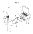
FIG. 1 is a schematic perspective view showing an embodiment of an endoscope system of the invention. -
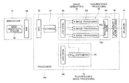
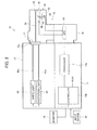
FIG. 2 is a conceptual block diagram showing the configuration of the endoscope system shown inFIG. 1 . -
FIG. 3 is a conceptual diagram showing the configuration of an excitation light cut filter and a high-sensitivity sensor. -
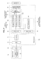
FIG. 4 is a conceptual block diagram showing a processor of the endoscope system shown inFIG. 1 . -
FIG. 5 shows spectra of autofluorescence emitted from a lesion area and a normal area of a living body. - On the following pages, the endoscope system of the invention is described in detail with reference to the preferred embodiments illustrated in the accompanying drawings.
-
FIG. 1 is a schematic perspective view showing an embodiment of the endoscope system of the invention andFIG. 2 conceptually shows the configuration of the endoscope system shown inFIG. 1 . - The illustrated
endoscope system 10 includes anendoscope 12, aprocessing device 14 for processing an image captured by theendoscope 12 and alight source device 16 for supplying white light and excitation light for use in the observation and imaging using theendoscope 12. - The
processing device 14 is connected to amonitor 18 for displaying an image captured by the endoscope and aninput device 20 for inputting various instructions. Theprocessing device 14 may further be connected to a printer (recording unit) for outputting an image captured by the endoscope as a hard copy. - The
endoscope system 10 of the invention is a system capable of so-called normal light observation using white light as observation light and so-called autofluorescence observation (hereinafter referred to as “fluorescence observation”) in which autofluorescence from a living tissue in an observation site exposed to excitation light is measured photometrically to form an image. - As shown in
FIG. 2 , theendoscope 12 is a so-called electronic endoscope which photoelectrically captures a biological image using an imaging device such as aCCD sensor 48. As in a common endoscope, theendoscope 12 includes aninsertion section 26, anoperating section 28, auniversal cord 30, aconnector 32 and avideo connector 36. - During the observation (diagnosis), the
endoscope 12 is used with thevideo connector 36 and theconnector 32 connected to a connectingportion 14 c of theprocessing device 14 and a connectingportion 16 a of thelight source device 16, respectively. As in a common endoscope, theconnector 32 is connected to a suction means and an air supply means for the suction from and the air supply to the observation site, and a water supply means for the water injection on the observation site. - As in a common endoscope, the
insertion section 26 or theendoscope 12 includes a longflexible portion 38 on the proximal side, a distal scope portion (endoscope distal portion) 42 provided with theCCD sensor 48 and the like, and a bending portion (angle portion) 40 located between theflexible portion 38 and thescope portion 42. Theoperating section 28 of theendoscope 12 includesmanipulation knobs 28 a for bending thebending portion 40 and an imaging button for capturing still images. - As schematically shown in
FIG. 2 , thescope portion 42 is provided with animaging lens 46, theCCD sensor 48, a high-sensitivity CCD sensor 50, an excitationlight cut filter 52, ahalf mirror 54, anillumination lens 56 and anoptical fiber 58. Thescope portion 42 also includes a cover glass (not shown) for protecting the lenses and the like. - Although not shown, the
endoscope 12 is also provided with a forceps channel and a forceps port for inserting various treatment tools such as a forceps, and air supply/water supply channels and air supply/water supply ports for use in suction, air supply and water supply. - The forceps channel extends through the
bending portion 40 and theflexible portion 38 to communicate with a forceps insertion port provided in theoperating section 28. The air supply/water supply channels extend through thebending portion 40, theflexible portion 38, theoperating section 28 and theuniversal cord 30 to communicate with connecting portions with the suction means, the air supply means and the water supply means in theconnector 32. - The
optical fiber 58 extends through thebending portion 40, theflexible portion 38, theoperating section 28 and theuniversal cord 30 and terminated by theconnector 32 which is connected to thelight source device 16. - White light and excitation light emitted from the
light source device 16 to be described later enters theoptical fiber 58 through theconnector 32 and propagates through theoptical fiber 58. In thescope portion 42, the light enters theillumination lens 56 from the distal end of theoptical fiber 58 and passes through theillumination lens 56 to be irradiated on an observation site. - Reflected light from the observation site of the living body irradiated with white light is imaged by the
CCD sensor 48. Autofluorescence (hereinafter referred to as “fluorescence”) from a living tissue in the observation site exposed to excitation light and reflected light on the living body exposed to excitation light are imaged by the high-sensitivity CCD sensor 50. - The
CCD sensor 48 is a common color CCD sensor which measures R (red) light, G (green) light and B (blue) light photometrically to form (capture) color images and is used in a common endoscope or digital camera. Therefore, theCCD sensor 48 outputs signals of an R image, a G image and a B image. - On the other hand, the high-sensitivity CCD sensor 50 (hereinafter referred to as “high-
sensitivity sensor 50”) is the one which is used to measure R (red) light, G (green) light and B (blue) light photometrically and which can also detect weak incident light with a small quantity of light to output signals. Therefore, the high-sensitivity sensor 50 outputs signals of an R image, a G image and a B image. - The
scope portion 42 including theCCD sensor 48 and high-sensitivity sensor 50 as described above will be described later in detail. - In the practice of the invention, the imaging device is not limited to the
CCD sensor 48 and various known imaging devices such as a CMOS image sensor may be used. - The high-sensitivity sensor is not limited to the high-sensitivity CCD sensor and various known imaging devices such as a CMOS image sensor may be used as long as they are highly sensitive.
- Output signals from the
CCD sensor 48 and the high-sensitivity sensor 50 are sent on signal lines from thescope portion 42 to thevideo connector 36 through the bendingportion 40, theflexible portion 38, oneoperating section 28, theuniversal cord 30 and theconnector 32. - In the illustrated embodiment, an AFE (Analog Front End)
board 64 is disposed in thevideo connector 36. - The
AFE board 64 includes, for example, a correlated double sampling circuit, an amplifier (automatic gain control circuit) and an A/D converter. In theAFE board 64, the output signals from theCCD sensor 48 and the high-sensitivity sensor 50 are subjected to noise removal by correlated double sampling and amplification in the amplifier. The amplified signals are further converted in the A/D converter from analog form to digital form to obtain digital image signals. The digital image signals are then outputted to the processing device 14 (more specifically to aDSP 72 to be described later). - In the endoscope system of the invention, these processing steps may be performed in the
connector 32 or theprocessing device 14 instead of thevideo connector 36. - As described above, the
connector 32 of theendoscope 12 in theendoscope system 10 is connected to the connectingportion 16 a of thelight source device 16. - The
light source device 16 supplies to theendoscope 12 white light for the normal light observation in the living body and excitation light for emitting fluorescence from the living tissue. As described above, the white light and excitation light supplied from thelight source device 16 toward theendoscope 12 enters theoptical fiber 58 through theconnector 32 and propagates therethrough to be irradiated on the observation site through thescope portion 42 at the distal end of theinsertion section 26. - As schematically shown in
FIG. 2 , thelight source device 16 of theendoscope system 10 includes awhite light source 60 for emitting white light for use in the normal light observation, anexcitation light source 62 for emitting excitation light for use in the fluorescence observation, andoptical fibers - The
white light source 60 emits white light which is observation light for use In the so-called normal light observation in the endoscope. - In the illustrated
endoscope system 10, the normal light observation using white light as observation light can be performed by capturing an image only using thewhite light source 60 as the light source and the CCD sensor 48 (color CCD sensor) as the imaging means. - The
white light source 60 is not particularly limited and various light sources capable of emitting white light and used in endoscope systems, as exemplified by a xenon lamp and a natural light LED may be employed. - A light source (light source device) using given phosphors which is illustrated in commonly assigned JP 2009-56248 A is also advantageously used for the
white light source 60. Light in a first wavelength range emitted from the light source excites the phosphors to generate light in a second wavelength range and the light in the first wavelength range is combined with the light in the second wavelength range to generate white illumination light. - On the other hand, the
excitation light source 62 is a light source emitting excitation light which excites living tissues of the body such as porphyrin, NADH (reduced nicotinamide adenine dinucleotide), NADPH (reduced nicotinamide adenine dinucleotide phosphate) and FAD (flavin adenine dinucleotide) to emit (auto) fluorescence. - The excitation light is not particularly limited and light at any wavelength capable of exciting a living tissue to cause fluorescence therein can be all used.
- In particular, light at a wavelength of 370 to 470 nm (light having a peak (highest intensity) within this wavelength range) is advantageously used as the excitation light from the viewpoint that the opposite properties of R fluorescence and G fluorescence from the living tissue in terms of the emission intensity which will be described later can be advantageously exhibited. Light at a wavelength of 400 to 450 nm can be more advantageously used because the opposite properties are exhibited and the biological safety can be more reliably ensured.
- Various light sources capable of emitting, at a sufficient intensity, excitation light causing fluorescence in living tissues can be ail used for the
excitation light source 62. - For example, various laser light sources such as a laser diode (LD) having a peak within the foregoing wavelength range are preferably used for the
excitation light source 62. A light source such as the one described in JP 2006-43289 A which uses a white light source such as a xenon lamp and a filter passing light in a predetermined wavelength range corresponding to the excitation light can also be used for theexcitation light source 62. - The white light emitted from the white light source 60 (observation light used in the normal light observation) is propagated through the
optical fiber 60 a, is supplied through the connectingportion 16 a to theconnector 32 of theendoscope 12 and then supplied to theoptical fiber 58 from theconnector 32. On the other hand, the excitation light emitted from theexcitation light source 62 is propagated through theoptical fiber 62 a, is likewise supplied through theconnection portion 16 a to theconnector 32 of theendoscope 12 and then supplied to theoptical fiber 58 from theconnector 32. - The white light and excitation light having been supplied to the
optical fiber 58 are propagated through theoptical fiber 58, exit from the distal end of theoptical fiber 58 on the side of thescope portion 42 and pass through theillumination lens 56 to be irradiated on the observation site in the living body. - Reflected light from the observation site of the body irradiated with the white light and fluorescence emitted from the living tissue in the observation site irradiated with the excitation light are captured and imaged via the
imaging lens 46 and thehalf mirror 54 by theCCD sensor 48 and the high-sensitivity sensor 50, respectively. - More specifically, the
half mirror 54 is disposed on the optical axis of theimaging lens 46 in thescope portion 42. Light which passed through thehalf mirror 54 is incident on theCCD sensor 48 to form an image whereas light which was reflected on thehalf mirror 54 is incident on the excitation light cutfilter 52, through which part of light passes to be incident on the high-sensitivity sensor 50 to form an image therein. - When the excitation light is irradiated to capture autofluorescence images in the illustrated
endoscope system 10, B elements of the high-sensitivity sensor 50 receive the excitation light reflected on the observation site of the living body to image the structure thereof. On the other hand, R and G elements of the high-sensitivity sensor 50 receive autofluorescence light. - Therefore, the excitation light cut filter is configured to block light in the wavelength band of the excitation light at predetermined positions corresponding to the R and G elements.
-
FIG. 3 is a conceptual diagram showing the configuration of the excitation light cutfilter 52 and the high-sensitivity sensor 50. - As shown in
FIG. 3 , the excitation light cutfilter 52 is a filter which blocks light in the wavelength band of the excitation light at the positions corresponding to the R and G elements of the high-sensitivity sensor 50. - More specifically, part of the light having passed through the
imaging lens 46 is incident on the excitation light cutfilter 52, through which light at wavelengths outside the wavelength band of the excitation light passes to be incident on the R and G elements of the high-sensitivity sensor 50. - On the other hand, the light to be received by the B elements of the high-
sensitivity sensor 50 all passes through the excitation light cutfilter 52 irrespective of the wavelength. - In other words, when the excitation light is irradiated to capture the autofluorescence images, the high-
sensitivity sensor 50 detects R light from the autofluorescence in the R elements, G light from the autofluorescence in the G elements and R light as the reflected excitation light in the B elements. The autofluorescence images are generated from the R fluorescence, the G fluorescence and the B reflected light detected by the high-sensitivity sensor 50. - As described above, the autofluorescence generated in the living tissue exposed to the excitation light has a low intensity or a small amount of light emission. Therefore, the entrance of the reflected excitation light into the R and G elements of the high-
sensitivity sensor 50 for detecting the fluorescence may cause noise to hinder the precise detection of the R and G light from the autofluorescence. - In contrast, the high-
sensitivity sensor 50 can detect weak R and G light from the autofluorescence with high precision by disposing the excitation light cutfilter 52 for blocking light in the wavelength band of the excitation light at the positions corresponding to the R and G elements of the high-sensitivity sensor 50. - As described above, the high-
sensitivity sensor 50 detects the excitation light reflected on the observation site of the living body at the B elements. In other words, the B elements which do not detect the autofluorescence light detect the excitation light reflected on the observation site of the living body to image the structure of the observation site of the living body. The structure of the observation site which is not obtainable from the detection of the R light and G light from the autofluorescence can be thus obtained as a monochrome image (B intensity image). - The configuration in which the B elements do not detect the autofluorescence light but the excitation light reflected on the observation site of the living body enables autofluorescence images and reflected light images to be obtained with one sensor and it is therefore not necessary to provide a sensor for imaging the structure of an observation site separately from a sensor for capturing autofluorescence images when the fluorescence observation is performed.
- Various filters which block the excitation light and pass light on the longer wavelength side than the wavelength band of the excitation light (wavelength band including at least an R light region) at the positions corresponding to the R and G elements of the high-
sensitivity sensor 50 can be used for the excitation light cutfilter 52. - An exemplary filter that may be used includes one which blocks light at wavelengths equal to or shorter than the maximum wavelength of the excitation light and passes light on the longer wavelength side than the maximum wavelength of the excitation light. More specifically, when the
excitation light source 62 is a laser light source having a central wavelength of 400 nm, the excitation light cutfilter 52 which blocks light at wavelengths equal to or shorter than 420 nm and preferably equal to or shorter than 410 nm, and passes light at wavelengths on the longer wavelength side may be used. - When the excitation light is produced by a band-limiting filter such as the one described in JP 2006-43289 A, various known excitation light cut filters including the one described therein can be used.
- When the normal light observation is performed in the
endoscope system 10, the white light (observation light) is continuously emitted only from thewhite light source 60 of thelight source device 16 to image only in theCCD sensor 48 thereby capturing normal light observation images as in the normal light observation using a common endoscope system. - On the other hand, when the fluorescence observation is performed, the
light source device 16 continuously emits excitation light only from theexcitation light source 62 to image in the high-sensitivity sensor 50 thereby capturing autofluorescence images. - The invention uses the
half mirror 54 to change the optical path to supply light to one of theCCD sensor 18 and the high-sensitivity sensor 50 but the invention is not limited to this configuration. For example, a total reflection mirror may be inserted into or retracted from the optical path so that the subsequent optical path is directed to theCCD sensor 48 or the high-sensitivity sensor 50. - As shown, the endoscope used in the
endoscope system 10 of the invention is of a so-called one-lens two-sensor configuration in which two imaging devices for use in the normal light observation and fluorescence observation are provided for oneimaging lens 46, and theCCD sensor 48 and the high-sensitivity sensor 50 are selectively used by changing the optical path. However, the invention is not limited to this. For example, a two-lens two-sensor configuration may be used in which an imaging device for use in the normal light observation and an imaging device for use in the fluorescence observation each have the corresponding imaging lens as long as the same observation site can be imaged by switching between the normal light observation image mode and the fluorescence image mode. - As described above, output signals from the
CCD sensor 48 and the high-sensitivity sensor 50 are sent to thevideo connector 36, subjected to processing such as A/D conversion in theAFE 64 and supplied to the processing device 14 (more specifically aprocessor 14 a thereof) as a digital image (digital image signals (image data/image information)). - The
processing device 14 subjects the normal light observation images and autofluorescence images (hereinafter also collectively referred to simply as “images” when it is not necessary to distinguish them from each other) supplied (outputted) from theendoscope 12 to predetermined processing so that themonitor 18 displays them as the images captured by theendoscope 12 and also controls theendoscope system 10. - In the illustrated embodiment, the
processing device 14 includes theimage processor 14 a and acontroller 14 b for controlling the whole of theendoscope system 10 including theprocessing device 14. -
FIG. 4 is a conceptual block diagram showing theimage processor 14 a of theprocessing device 14. - As shown in
FIG. 4 , theprocessor 14 a includes theDSP 72, astorage section 74, animage generating section 76, a fluorescenceimage processing section 78 and a displayimage generating section 80. - In the
processing device 14, images from theendoscope 12 are supplied to theDSP 72. - The
DSP 72 is a known type of DSP (Digital Signal Processor), where the supplied autofluorescence images are subjected to predetermined processing steps such as gamma correction and color correction. The processed images are then stored in a predetermined region of the storage section (memory) 74. - Upon the storage of the normal light images or autofluorescence images in the
storage section 74, theimage generating section 76 or the fluorescenceimage processing section 78 reads out images and performs predetermined processing on the read-out images. - The fluorescence
image processing section 78 includes a read-outportion 84 and an RF/GFarithmetic portion 86. The fluorescenceimage processing section 78 only functions when the fluorescence observation is performed. - In the case of the fluorescence observation, once the
storage section 74 stores the autofluorescence images captured by the high-sensitivity sensor 50, the read-outportion 84 of the fluorescenceimage processing section 78 which is under the control of thecontroller 14 b reads out the autofluorescence images and supplies them to the RF/GFarithmetic portion 86. As described above, in the case of the fluorescence observation, the high-sensitivity sensor 50 photometrically measures R light and G light as autofluorescence emitted from the living tissue exposed to the excitation light and B light as light reflected from the living body when the excitation light enters the observation site, thereby capturing the autofluorescence images. Therefore, the read-outportion 84 reads out the r fluorescence image RF and the G fluorescence image GF and supplies them to the RF/GFarithmetic portion 86. - The RF/GF
arithmetic portion 86 uses the supplied fluorescence images RF and GF to calculate the ratio RF/GF between the fluorescence image RF and the fluorescence image GF and supply the calculated ratio to afluorescence processing portion 92 of theimage generating section 76 to be described below. - On the other hand, the image generating section 7 6 includes a read-out
portion 90, thefluorescence processing portion 92 and animage correcting portion 94. - Under the control of the controller 154 b, the read-out
portion 90 of theimage generating section 76 reads out images stored in thestorage section 74. - In the case of the normal light observation, normal light images are stored in the
storage section 74. Therefore, when the normal light observation is performed, the read-outportion 90 reads out an R normal image RN, a G normal image GN and a B normal image BN. - On the other hand, in the case of the fluorescence observation, autofluorescence images are stored in the
storage section 74. Therefore, an R fluorescence image RF, a G fluorescence image GF and a B fluorescence image BF are read out by the read-outportion 90. - The
fluorescence processing portion 92 only functions when the fluorescence imaging is performed. Therefore, when the normal light observation is performed, the normal images RN, GN and BN read out by the read-outportion 84 pass through thefluorescence processing portion 92 to be directly supplied to theimage correcting portion 94 as an R image RD, a G image GD and a B image BD without being processed in thefluorescence processing portion 92. - The
image correcting portion 94 subjects the R, G and B images to processing with a 3×3 matrix, gradation conversion, processing with a three-dimensional LUT or other color conversion processing; color enhancement for giving a color difference between a blood vessel and a mucous membrane on the screen by enhancing in a direction in which the color difference between the blood vessel and the mucous membrane is to be more accentuated than the average colors of the image so that the blood vessel can be more easily seen; image structure enhancement such as sharpening and edge enhancement, and other image correction steps and supplies the corrected image to the displayimage generating section 80 as the images for display. - In contrast, when the fluorescence observation is performed, the R fluorescence image RF, the G fluorescence image GF and the B fluorescence image BF read out by the read-out
portion 90 are supplied to theimage correcting portion 94 as an R image RD, a G image GD and a B image BD after being subjected to predetermined processing in thefluorescence processing portion 92. Theimage correcting portion 94 performs the same image correction as above and sends the corrected images to the displayimage generating section 80 as the images for display. - The
fluorescence processing portion 92 includes an Rimage processing portion 92 r, a Gimage processing portion 92 g and a 3image processing portion 92 b. The image processing portions process the autofluorescence images (respective pixels thereof) using the ratio RF/GF calculated by the RF/GF arithmetic portion 86 (RF/GF for the respective pixels of the autofluorescence images). More specifically, the Rimage processing portion 92 r processes the fluorescence image RF to generate the R image RD, the Gimage processing portion 92 g processes the fluorescence image GF to generate the G image GD and the Bimage processing portion 92 b processes the fluorescence image BF to generate the B image BD. - More specifically, in the illustrated case, the image processing portions of the
fluorescence processing portion 92 process the autofluorescence images with RF/GF by the following formulas (1) to (3) to generate the images RD, GD and BD, respectively. -
R D =R F×|1+α×(R F /G F)| (1) -
G D =G F×├1−α×(R F /G F)| (2) -
BD=BF (3) - In the above formula, α is a preferably used coefficient which is appropriately set so that RF/GF in the lesion area may approach 1 and more preferably RF/GF in the normal area may approach 0.
-
FIG. 5 shows spectra of autofluorescence from a living tissue when a living body (human colonic mucosa) is irradiated with light at a central wavelength of 380 nm emitted from the laser light source as excitation light. - In
FIG. 5 , the horizontal axis shows the autofluorescence wavelength and the vertical axis shows the autofluorescence intensity, and the solid line shows the autofluorescence from the lesion area and the broken line shows the autofluorescence from the normal area. - In the fluorescence generated by exposure to B light or blue-violet light as excitation light, it is considered that the R fluorescence image RF is mainly formed by R fluorescence due to porphyrin and the G fluorescence image GF is mainly formed by G fluorescence due to NADH and NADPH.
- As for the R fluorescence making up the fluorescence image RF, as is seen from, for example, the fluorescence property at around 630 nm, the normal area does not show very strong fluorescence whereas the lesion area shows very strong fluorescence. On the other hand, as for the G fluorescence making up the fluorescence image GF, as is seen from, for example, the fluorescence property at around 470 nm to 530 nm, the normal area shows strong fluorescence whereas the lesion area does not show very strong fluorescence. In other words, the fluorescence image RF and the fluorescence image GF obtained by exposure of the living tissue to B light as excitation light have opposite properties in terms of the intensity in the normal area and the lesion area.
- The lesion area can be enhanced by making use of the opposite properties of the fluorescence image RF and the fluorescence image GF in the lesion area and the normal area.
- More specifically, the lesion area has a higher intensity in the fluorescence image RF and a lower Intensity in the fluorescence image GF and the ratio RF/GF is therefore increased. On the other hand, the normal area has a lower intensity in the fluorescence image RF and a higher intensity in the fluorescence image GF and the ratio RF/GF is therefore decreased. Accordingly, this relation is used to process the fluorescence image RF as the autofluorescence image by, for example, multiplication or addition of RF/GF to enhance the lesion area of the autofluorescence image, thus enabling the lesion area of the obtained image to be enhanced with red. The fluorescence image GF as the autofluorescence image is processed by, for example, division or subtraction of RF/GF to suppress the lesion area in the fluorescence image GF as the autofluorescence image, thus enabling the lesion area of the obtained image to be enhanced with the fluorescence image RF, that is, with red.
- As described above, the fluorescence image BF is an image acquired by detecting the reflected excitation light and includes the biological structure and therefore the fluorescence image BF is not processed with RF/GF but is directly used as the image BD as shown in formula (3), whereby the biological structure can be suitably displayed on the image.
- In the illustrated case, use is preferably made of the coefficient α which is set so that RF/GF is closer to 1 in the lesion area having a larger RF/GF and is closer to 0 in the normal area having a smaller RF/GF.
- In the R image, α×RF/GF is added to 1 and multiplied by the fluorescence image RF to calculate the image RD. On the other hand, in the G image, α×RF/GF is subtracted from 1 and multiplied by the fluorescence image GF to calculate the image GD.
- Therefore, in each of the autofluorescence images processed in the
fluorescence processing portion 92, RF/GF is or is close to 0 in the normal area and the normal images including R, G and B images are multiplied by 1 or a value close to 1. Therefore, the normal area has no large image changes between the autofluorescence images and the images RD, GD and BD, respectively. - In contrast, in each of the autofluorescence images processed in the
fluorescence processing portion 92, the fluorescence image RF is multiplied by 2 or a value close to 2 in the lesion area and the image RD is enhanced twice as large as that of the fluorescence image RF. In the lesion area, the fluorescence image GF is multiplied by 0 or a value closer to 0 and the image GD has a value close to 0. - In other words, in this example, the lesion area of the obtained image is enhanced with red with respect to the normal area.
- As is clear from the above description, by making use of the opposite properties of the fluorescence images RF and GF in the normal area and lesion area, the invention can enhance the fluorescence image RF having an increased autofluorescence intensity in the lesion area and suppress the fluorescence image GF showing no very high fluorescence in the lesion area, thereby highlighting the lesion area with the color of the fluorescence image RF.
- Therefore, according to the endoscope system of the invention, fluorescence images with enhanced lesion area can be used to correctly identify the lesion area and the normal area.
- As described above, the coefficient α is preferably used in the processing of the normal images with RF/GF in the
fluorescence processing portion 92 and is appropriately set so that RF/GF may approach 1 in the lesion area. The coefficient α is more preferably a coefficient appropriately set so that RF/GF in the lesion area may approach 1 and RF/GF in the normal area may approach 0. - Use of the coefficient α as described above enables the lesion area to be suitably enhanced in a well-balanced manner while preventing the image of each color from being unnecessarily increased or decreased.
- The coefficient α as described above may be appropriately set according to the device characteristics of the
endoscope 12 and thelight source device 16 such as the spectral sensitivity characteristics of the nigh-sensitivity sensor 50 (band characteristics of the filter and the spectral sensitivity of the device), the wavelength of the excitation light emitted from the light source device 16 (spectral characteristics), and the spectral characteristics of the excitation light cut filter 52 (filter characteristics) so that RF/GF nay approach or be 1 in the lesion area. Preferably, the coefficient α is appropriately set according to the device characteristics so that RF/GF may approach 1 in the lesion area and approach or be 0 in the normal area. - As described above, the coefficient α is preferably used and is not essential. Depending on the foregoing device characteristics of the
endoscope system 10, RF/GF may take a value close to 1 in the lesion area and optionally a value close to 0 in the normal area without using the coefficient α. - The processing of the fluorescence images RF and GF includes the addition or subtraction of RF/GF to or from 1 but the invention is not limited thereto. For example, RF/GF may be directly multiplied by the fluorescence images to calculate the images RD and GD. Alternatively, RF/GF may be directly added to or subtracted from the fluorescence images to calculate the images RD and GD.
- In addition, in the above examples, the R and G images are processed with a correction factor including RF/GF but the B image is net processed with a correction factor including RF/GF, thus calculating the images RD, GD and BD. However, the invention is not limited to this method.
- For example, the images RD, GD and BD may be calculated by the operation represented by the formula (1) for the a image, by the operation represented by the formula (2) for the G image, and by the processing with a correction factor including RF/GF for the B image as represented by the formula: BD=BF×|1−α×(RF/GF)|. Alternatively, the images RD, GD and BD may be calculated by performing the operation represented by the formula (1) for the R image and performing no processing on the G and B images.
- Alternatively the images RD, GD and BD may be calculated by performing no processing on the R image, performing the operation represented by the formula (2) for the G image and performing the operation represented by the formula: BD=BF×|1−α×(RF/GF)| for the B image so that the G and B images are suppressed while the R image is enhanced.
- As described above, in the case of the normal light observation, the normal images RN, GN and BN read out by the read-out
portion 90 are not processed in thefluorescence processing portion 92 and are supplied to theimage correcting portion 94 as the images RD, GD and BD. In the case of the fluorescence observation, the autofluorescence images RF, GF and BF read out by the read-outportion 90 are processed with RF/GF in thefluorescence processing portion 92 and supplied to theimage correcting portion 94 as the images RD, GD and BD. - The images RD, GD and BD are subjected to predetermined processing such as color conversion or image structure enhancement in the
image correcting portion 94 before being supplied to the displayimage generating section 80 as images for display (normal light observation images/fluorescence images). - The display
image generating section 80 subjects the normal light observation images and fluorescence images supplied from theimage generating section 76 to color space conversion, scaling and other necessary processing steps, or image allocation, incorporation of character information such as the name of a subject and other necessary processing steps to generate a display image having the composite image incorporated therein and this image is displayed on themonitor 18. - An example of the operation of the
endoscope system 10 is described below for the case of the fluorescence observation. - When the
input device 20 issues an instruction for the start of imaging with theendoscope 12, theexcitation light source 62 of thelight source device 16 is turned on. In theendoscope 12, the high-sensitivity sensor 50 of theendoscope 12 simultaneously starts imaging. - The excitation light emitted from the
excitation light source 62 is propagated through theoptical fiber 62 a and is supplied through theconnection portion 16 a to the connector 22 of theendoscope 12. - The excitation light supplied to the
connector 32 of theendoscope 12 is propagated through theoptical fiber 58 to thescope portion 42, where the excitation light exit from the distal end of theoptical fiber 58 to be irradiated on the observation site of the living body. - The high-
sensitivity sensor 50 captures the excitation light irradiated on the observation site to output autofluorescence images composed of the R fluorescence and G fluorescence from the living tissue of the observation site and the reflected 3 light of the excitation light. - Output signals from the high-
sensitivity sensor 50 are supplied to theAFE board 64. TheAFE board 64 subjects the output signals from the high-sensitivity sensor 50 to noise removal by correlated double sampling, amplification and A/D conversion to obtain digital image signals, which are then supplied to theDSP 72 of the processing device 14 (processor 14 a). - The
DSP 72 subjects the supplied images (image signals) to predetermined processing such as gamma correction and color correction and the processed images are stored in a predetermined portion of thestorage unit 74. - Once the image signals are stored in the
storage section 74, the read-outportion 84 of the fluorescenceimage processing section 78 roads out the R fluorescence image RF and the G fluorescence image GF captured by the high-sensitivity sensor 50 and supplies them to the RF/GFarithmetic portion 86. - The RF/GF
arithmetic portion 86 calculates RF/GF and supplies it to the fluorescence processing portion 92 (Rimage processing portion 92 r, Gimage processing portion 92 g and Bimage processing portion 92 b). - The read-out
portion 90 of theimage generating section 76 reads out the R fluorescence image RF, G fluorescence image GF and B fluorescence image BF and supplies them to thefluorescence processing portion 92. - In the
fluorescence processing portion 92, the Rimage processing portion 92 r, the Gimage processing portion 92 g and the Bimage processing portion 92 b process the fluorescence image RF, fluorescence image GF and fluorescence image BF by the formulas (1), (2) and (3) using RF/GF to obtain the images RD, GD and BD, respectively. - The images RD, GD and BD obtained in the
fluorescence processing portion 92 are then subjected to predetermined image correction steps such as color conversion and image structure processing in theimage correcting portion 94. A display image is generated in the displayimage generating section 80 and is displayed on themonitor 18 as a fluorescence image. - As described above, the display image is an image in which the lesion area captured in the fluorescence observation mode is enhanced with red and therefore the normal area and lesion area are easily identified.
- While the endoscope system of the invention has been described above in detail, the invention is by no means limited to the above embodiments, and various improvements and modifications may of course be made without departing from the spirit of the invention.
- For example, the illustrated
endoscope system 10 is configured so that the B elements of the high-sensitivity sensor 50 detect the excitation light reflected on the observation site of the living body to capture the biological structure as a monochrome image in the fluorescence observation mode. However, this is not the sole case of the invention and the B elements of tho high-sensitivity sensor 50 may detect nothing in the fluorescence observation mode. When the high-sensitivity sensor 50 is configured so that the B elements detect nothing, the R or G image may be allocated to the B image. - The illustrated
endoscope system 10 is also configured so that the images obtained by the operations of the fluorescence images RF, GF and BF ate allocated to the images RD, GD and BD, respectively, as shown in the formulas (1) to (3). However, this is not the sole case of the invention and the images obtained by the operations of the fluorescence images may be allocated by any combination. - For example, the image obtained by the operation of the fluorescence image RF may be allocated to the image GD as represented by the formula: GD=RF×|1+α×(RF/GF)|, the image obtained by the operation of the fluorescence image GF be allocated to the image BD as represented by the formula: BD=GF×|1−α×(RF/GF)| and the image obtained by the operation of the fluorescence image BF be allocated to the image RD as represented by the formula: RD=BF.
Claims (11)
1. An endoscope system comprising:
an endoscope for photoelectrically capturing images in a living body;
a light source device including a light source for fluorescence observation which emits excitation light exciting a fluorescence component in the living body to cause the fluorescence component to emit fluorescence; and
processing means for processing autofluorescence images captured in said endoscope by irradiation with said excitation light, using a G fluorescence signal and an R fluorescence signal obtained by capturing in said endoscope the fluorescence emitted from said fluorescence component in the living body irradiated with said excitation light.
2. The endoscope system according to claim 1 , wherein said light source for fluorescence observation emits light at a wavelength of 370 to 470 nm as said excitation light.
3. The endoscope system according to claim 1 , wherein said endoscope receives reflected light of said excitation light emitted from said light source for fluorescence observation to acquire a B reflection signal as a B signal in said autofluorescence images.
4. The endoscope system according to claims 1 , wherein said processing means uses a ratio of the R fluorescence signal to the G fluorescence signal obtained by dividing the R fluorescence signal by the G fluorescence signal to process said autofluorescence images.
5. The endoscope system according to claim 4 , wherein said processing means multiplies at least one of the autofluorescence image signals including the R fluorescence signal, the G fluorescence signal and a B reflection signal by a correction factor including said ratio of the R fluorescence signal to the G fluorescence signal to process said autofluorescence images.
6. The endoscope system according to claim 5 , wherein said processing means multiplies said R fluorescence signal by the correction factor obtained by adding said ratio of the R fluorescence signal to the G fluorescence signal to 1 to process said auto fluorescence images.
7. The endoscope system according to claim 6 , wherein said processing means multiplies said ratio of the R fluorescence signal to the G fluorescence signal by a predetermined coefficient α and adds a resultant obtained by multiplication to 1 to generate said correction factor.
8. The endoscope system according to claims 4 , wherein said processing means multiplies at least one of said G fluorescence signal and a B reflection signal by a correction factor obtained by subtracting said ratio of the R fluorescence signal to the G fluorescence signal from 1 to process said autofluorescence images.
9. The endoscope system according to claim 8 , wherein said processing means multiplies said ratio of the R fluorescence signal to the G fluorescence signal by a predetermined coefficient α and subtracts a resultant obtained by multiplication from 1 to generate said correction factor.
10. The endoscope system according to claims 3 , wherein said processing means does not subject said B reflection signal to processing using a correction factor including a ratio of the R fluorescence signal to the G fluorescence signal to process said autofluorescence images.
11. The endoscope system according to claims 1 ,
wherein said endoscope comprises a solid-state image sensor for capturing the fluorescence emitted from said fluorescence component in the living body by irradiation with said excitation light, and
wherein R and G elements of said solid-state image sensor captures the fluorescence emitted from said fluorescence component in the living body via a filter through which said excitation light does not pass but said fluorescence emitted from said fluorescence component in the living body passes.
Applications Claiming Priority (2)
| Application Number | Priority Date | Filing Date | Title |
|---|---|---|---|
| JP2011008571A JP5485190B2 (en) | 2011-01-19 | 2011-01-19 | Endoscope device |
| JP2011-008571 | 2011-01-19 |
Publications (1)
| Publication Number | Publication Date |
|---|---|
| US20120184813A1 true US20120184813A1 (en) | 2012-07-19 |
Family
ID=45478142
Family Applications (1)
| Application Number | Title | Priority Date | Filing Date |
|---|---|---|---|
| US13/340,471 Abandoned US20120184813A1 (en) | 2011-01-19 | 2011-12-29 | Endoscope system |
Country Status (3)
| Country | Link |
|---|---|
| US (1) | US20120184813A1 (en) |
| EP (1) | EP2478826A1 (en) |
| JP (1) | JP5485190B2 (en) |
Cited By (13)
| Publication number | Priority date | Publication date | Assignee | Title |
|---|---|---|---|---|
| US20120197080A1 (en) * | 2011-02-01 | 2012-08-02 | Jin Murayama | Electronic endoscope system |
| US20140078279A1 (en) * | 2011-06-03 | 2014-03-20 | Olympus Corporation | Fluorescence observation apparatus and fluorescence observation method |
| US20170115223A1 (en) * | 2014-04-03 | 2017-04-27 | Hitachi High-Technologies Corporation | Fluorescence Spectrometer |
| US10076238B2 (en) | 2011-09-22 | 2018-09-18 | The George Washington University | Systems and methods for visualizing ablated tissue |
| US10143517B2 (en) | 2014-11-03 | 2018-12-04 | LuxCath, LLC | Systems and methods for assessment of contact quality |
| US10292592B2 (en) * | 2014-11-13 | 2019-05-21 | The Board Of Trustees Of The Leland Stanford Junior University | Method and apparatus for optical recording of biological parameters in freely moving animals |
| US10722301B2 (en) | 2014-11-03 | 2020-07-28 | The George Washington University | Systems and methods for lesion assessment |
| US10736512B2 (en) | 2011-09-22 | 2020-08-11 | The George Washington University | Systems and methods for visualizing ablated tissue |
| US10779904B2 (en) | 2015-07-19 | 2020-09-22 | 460Medical, Inc. | Systems and methods for lesion formation and assessment |
| US11096584B2 (en) | 2013-11-14 | 2021-08-24 | The George Washington University | Systems and methods for determining lesion depth using fluorescence imaging |
| US20210393116A1 (en) * | 2019-03-05 | 2021-12-23 | Olympus Corporation | Endoscope device and image processing method |
| US11457817B2 (en) | 2013-11-20 | 2022-10-04 | The George Washington University | Systems and methods for hyperspectral analysis of cardiac tissue |
| US11882995B2 (en) * | 2017-02-01 | 2024-01-30 | Olympus Corporation | Endoscope system |
Families Citing this family (1)
| Publication number | Priority date | Publication date | Assignee | Title |
|---|---|---|---|---|
| WO2014156493A1 (en) * | 2013-03-29 | 2014-10-02 | オリンパス株式会社 | Fluorescence observation device |
Citations (17)
| Publication number | Priority date | Publication date | Assignee | Title |
|---|---|---|---|---|
| US4605955A (en) * | 1982-05-07 | 1986-08-12 | Nippon Kogaku K.K. | Color balance adjusting apparatus for color television cameras |
| US5092331A (en) * | 1989-01-30 | 1992-03-03 | Olympus Optical Co., Ltd. | Fluorescence endoscopy and endoscopic device therefor |
| US5769792A (en) * | 1991-07-03 | 1998-06-23 | Xillix Technologies Corp. | Endoscopic imaging system for diseased tissue |
| US6364829B1 (en) * | 1999-01-26 | 2002-04-02 | Newton Laboratories, Inc. | Autofluorescence imaging system for endoscopy |
| US6465968B1 (en) * | 1999-11-02 | 2002-10-15 | Fuji Photo Film Co., Ltd. | Method and apparatus for displaying fluorescence information |
| US6468204B2 (en) * | 2000-05-25 | 2002-10-22 | Fuji Photo Film Co., Ltd. | Fluorescent endoscope apparatus |
| US6473637B1 (en) * | 1999-11-16 | 2002-10-29 | Fuji Photo Film Co., Ltd. | Method and apparatus for displaying fluorescence images |
| US6571119B2 (en) * | 1996-03-06 | 2003-05-27 | Fuji Photo Film Co., Ltd. | Fluorescence detecting apparatus |
| US6790174B2 (en) * | 1997-09-24 | 2004-09-14 | Olympus Corporation | Fluorescent imaging device |
| US20050059894A1 (en) * | 2003-09-16 | 2005-03-17 | Haishan Zeng | Automated endoscopy device, diagnostic method, and uses |
| US6960165B2 (en) * | 2001-05-16 | 2005-11-01 | Olympus Corporation | Endoscope with a single image pick-up element for fluorescent and normal-light images |
| US20060173358A1 (en) * | 2005-01-11 | 2006-08-03 | Olympus Corporation | Fluorescence observation endoscope apparatus and fluorescence observation method |
| US7179222B2 (en) * | 1996-11-20 | 2007-02-20 | Olympus Corporation | Fluorescent endoscope system enabling simultaneous achievement of normal light observation based on reflected light and fluorescence observation based on light with wavelengths in infrared spectrum |
| US7235045B2 (en) * | 1998-01-26 | 2007-06-26 | Massachusetts Institute Of Technology | Fluorescence imaging endoscope |
| US20090216085A1 (en) * | 2008-02-27 | 2009-08-27 | Olympus Medical Systems Corp. | Fluorescent endoscopic device and method of creating fluorescent endoscopic image |
| US7697975B2 (en) * | 2003-06-03 | 2010-04-13 | British Colombia Cancer Agency | Methods and apparatus for fluorescence imaging using multiple excitation-emission pairs and simultaneous multi-channel image detection |
| US20110042580A1 (en) * | 2006-09-06 | 2011-02-24 | University Health Network | Fluorescence quantification and image acquisition in highly turbid media |
Family Cites Families (9)
| Publication number | Priority date | Publication date | Assignee | Title |
|---|---|---|---|---|
| JP3810337B2 (en) | 1991-05-08 | 2006-08-16 | ジリックス・テクノロジイズ・コーポレーション | Imaging device |
| US5647368A (en) * | 1996-02-28 | 1997-07-15 | Xillix Technologies Corp. | Imaging system for detecting diseased tissue using native fluorsecence in the gastrointestinal and respiratory tract |
| JP3796635B2 (en) * | 1996-03-06 | 2006-07-12 | 富士写真フイルム株式会社 | Fluorescence detection device |
| JP3654325B2 (en) * | 1997-02-13 | 2005-06-02 | 富士写真フイルム株式会社 | Fluorescence detection device |
| JP3923595B2 (en) * | 1997-05-13 | 2007-06-06 | オリンパス株式会社 | Fluorescence observation equipment |
| JP2001104237A (en) * | 1999-10-05 | 2001-04-17 | Fuji Photo Film Co Ltd | Method and device for judging fluorescence |
| JP4526322B2 (en) | 2004-08-06 | 2010-08-18 | オリンパス株式会社 | Endoscope device |
| JP4681981B2 (en) * | 2005-08-18 | 2011-05-11 | Hoya株式会社 | Electronic endoscope device |
| JP2009056248A (en) | 2007-09-03 | 2009-03-19 | Fujifilm Corp | Light source unit, drive control method of light source unit and endoscope |
-
2011
- 2011-01-19 JP JP2011008571A patent/JP5485190B2/en active Active
- 2011-12-29 US US13/340,471 patent/US20120184813A1/en not_active Abandoned
- 2011-12-29 EP EP11196079A patent/EP2478826A1/en not_active Withdrawn
Patent Citations (18)
| Publication number | Priority date | Publication date | Assignee | Title |
|---|---|---|---|---|
| US4605955A (en) * | 1982-05-07 | 1986-08-12 | Nippon Kogaku K.K. | Color balance adjusting apparatus for color television cameras |
| US5092331A (en) * | 1989-01-30 | 1992-03-03 | Olympus Optical Co., Ltd. | Fluorescence endoscopy and endoscopic device therefor |
| US5769792A (en) * | 1991-07-03 | 1998-06-23 | Xillix Technologies Corp. | Endoscopic imaging system for diseased tissue |
| US6571119B2 (en) * | 1996-03-06 | 2003-05-27 | Fuji Photo Film Co., Ltd. | Fluorescence detecting apparatus |
| US7179222B2 (en) * | 1996-11-20 | 2007-02-20 | Olympus Corporation | Fluorescent endoscope system enabling simultaneous achievement of normal light observation based on reflected light and fluorescence observation based on light with wavelengths in infrared spectrum |
| US6790174B2 (en) * | 1997-09-24 | 2004-09-14 | Olympus Corporation | Fluorescent imaging device |
| US7235045B2 (en) * | 1998-01-26 | 2007-06-26 | Massachusetts Institute Of Technology | Fluorescence imaging endoscope |
| US6364829B1 (en) * | 1999-01-26 | 2002-04-02 | Newton Laboratories, Inc. | Autofluorescence imaging system for endoscopy |
| US6465968B1 (en) * | 1999-11-02 | 2002-10-15 | Fuji Photo Film Co., Ltd. | Method and apparatus for displaying fluorescence information |
| US6473637B1 (en) * | 1999-11-16 | 2002-10-29 | Fuji Photo Film Co., Ltd. | Method and apparatus for displaying fluorescence images |
| US6468204B2 (en) * | 2000-05-25 | 2002-10-22 | Fuji Photo Film Co., Ltd. | Fluorescent endoscope apparatus |
| US6960165B2 (en) * | 2001-05-16 | 2005-11-01 | Olympus Corporation | Endoscope with a single image pick-up element for fluorescent and normal-light images |
| US7697975B2 (en) * | 2003-06-03 | 2010-04-13 | British Colombia Cancer Agency | Methods and apparatus for fluorescence imaging using multiple excitation-emission pairs and simultaneous multi-channel image detection |
| US20050059894A1 (en) * | 2003-09-16 | 2005-03-17 | Haishan Zeng | Automated endoscopy device, diagnostic method, and uses |
| US20060173358A1 (en) * | 2005-01-11 | 2006-08-03 | Olympus Corporation | Fluorescence observation endoscope apparatus and fluorescence observation method |
| US20110042580A1 (en) * | 2006-09-06 | 2011-02-24 | University Health Network | Fluorescence quantification and image acquisition in highly turbid media |
| US20090216085A1 (en) * | 2008-02-27 | 2009-08-27 | Olympus Medical Systems Corp. | Fluorescent endoscopic device and method of creating fluorescent endoscopic image |
| US8105232B2 (en) * | 2008-02-27 | 2012-01-31 | Olympus Medical Systems Corp. | Fluorescent endoscopic device and method of creating fluorescent endoscopic image |
Non-Patent Citations (1)
| Title |
|---|
| Lam, Hung, and Palcic. "Detection of Lung Cancer by Ratio Fluorometry with and without Photofrin II", Proc. SPIE 1201, Optical Fibers in Medicine V, 561 (July 1, 1990); doi:10.1117/12.17585 * |
Cited By (21)
| Publication number | Priority date | Publication date | Assignee | Title |
|---|---|---|---|---|
| US20120197080A1 (en) * | 2011-02-01 | 2012-08-02 | Jin Murayama | Electronic endoscope system |
| US8740778B2 (en) * | 2011-02-01 | 2014-06-03 | Fujifilm Corporation | Electronic endoscope system |
| US20140078279A1 (en) * | 2011-06-03 | 2014-03-20 | Olympus Corporation | Fluorescence observation apparatus and fluorescence observation method |
| US9516235B2 (en) * | 2011-06-03 | 2016-12-06 | Olympus Corporation | Fluorescence observation apparatus and fluorescence observation method |
| US10716462B2 (en) | 2011-09-22 | 2020-07-21 | The George Washington University | Systems and methods for visualizing ablated tissue |
| US10736512B2 (en) | 2011-09-22 | 2020-08-11 | The George Washington University | Systems and methods for visualizing ablated tissue |
| US11559192B2 (en) | 2011-09-22 | 2023-01-24 | The George Washington University | Systems and methods for visualizing ablated tissue |
| US10076238B2 (en) | 2011-09-22 | 2018-09-18 | The George Washington University | Systems and methods for visualizing ablated tissue |
| US11096584B2 (en) | 2013-11-14 | 2021-08-24 | The George Washington University | Systems and methods for determining lesion depth using fluorescence imaging |
| US11457817B2 (en) | 2013-11-20 | 2022-10-04 | The George Washington University | Systems and methods for hyperspectral analysis of cardiac tissue |
| US10451553B2 (en) * | 2014-04-03 | 2019-10-22 | Hitachi High-Technologies Corporation | Fluorescence spectrometer |
| US20170115223A1 (en) * | 2014-04-03 | 2017-04-27 | Hitachi High-Technologies Corporation | Fluorescence Spectrometer |
| US10682179B2 (en) | 2014-11-03 | 2020-06-16 | 460Medical, Inc. | Systems and methods for determining tissue type |
| US10722301B2 (en) | 2014-11-03 | 2020-07-28 | The George Washington University | Systems and methods for lesion assessment |
| US10143517B2 (en) | 2014-11-03 | 2018-12-04 | LuxCath, LLC | Systems and methods for assessment of contact quality |
| US11559352B2 (en) | 2014-11-03 | 2023-01-24 | The George Washington University | Systems and methods for lesion assessment |
| US11596472B2 (en) | 2014-11-03 | 2023-03-07 | 460Medical, Inc. | Systems and methods for assessment of contact quality |
| US10292592B2 (en) * | 2014-11-13 | 2019-05-21 | The Board Of Trustees Of The Leland Stanford Junior University | Method and apparatus for optical recording of biological parameters in freely moving animals |
| US10779904B2 (en) | 2015-07-19 | 2020-09-22 | 460Medical, Inc. | Systems and methods for lesion formation and assessment |
| US11882995B2 (en) * | 2017-02-01 | 2024-01-30 | Olympus Corporation | Endoscope system |
| US20210393116A1 (en) * | 2019-03-05 | 2021-12-23 | Olympus Corporation | Endoscope device and image processing method |
Also Published As
| Publication number | Publication date |
|---|---|
| JP5485190B2 (en) | 2014-05-07 |
| JP2012147927A (en) | 2012-08-09 |
| EP2478826A1 (en) | 2012-07-25 |
Similar Documents
| Publication | Publication Date | Title |
|---|---|---|
| US20120184813A1 (en) | Endoscope system | |
| US20120184812A1 (en) | Endoscope system | |
| US20170020377A1 (en) | Fluorescence observation endoscope system | |
| JP5303012B2 (en) | Endoscope system, processor device for endoscope system, and method for operating endoscope system | |
| JP5081720B2 (en) | Fluorescence endoscope apparatus and excitation light unit | |
| JP4855728B2 (en) | Illumination device and observation device | |
| US10244972B2 (en) | Fluorescence observation device, endoscopic system, processor device, and operation method | |
| US9456738B2 (en) | Endoscopic diagnosis system | |
| JP5302984B2 (en) | Endoscope system, processor device for endoscope system, and method for operating endoscope system | |
| JP5914496B2 (en) | ENDOSCOPE SYSTEM, PROCESSOR DEVICE, AND METHOD FOR OPERATING ENDOSCOPE SYSTEM | |
| WO2013035531A1 (en) | Endoscope system and image display method | |
| JP2013150713A (en) | Endoscope system, processor device for endoscope system, and image processing method | |
| EP2505121B1 (en) | Endoscope apparatus | |
| JP6100674B2 (en) | Endoscope light source device and endoscope system | |
| US20130053703A1 (en) | Endoscopic diagnosis system | |
| JP5147538B2 (en) | Fluorescence image acquisition device and method of operating fluorescence image acquisition device | |
| JP5780653B2 (en) | Light source device and endoscope system | |
| JP2012081048A (en) | Electronic endoscope system, electronic endoscope, and excitation light irradiation method | |
| JP5191327B2 (en) | Image acquisition device and method of operating image acquisition device | |
| JP2012090726A (en) | Electronic endoscope system, processor device of electronic endoscope system, and method for controlling illumination light | |
| JP2012050650A (en) | Endoscope system and calibration method thereof | |
| JP2019030406A (en) | Endoscope system | |
| JP6325707B2 (en) | Endoscope light source device and endoscope system | |
| JP6277068B2 (en) | Endoscope light source device and endoscope system | |
| JP5525991B2 (en) | Electronic endoscope system, processor device for electronic endoscope system, and method for operating electronic endoscope system |
Legal Events
| Date | Code | Title | Description |
|---|---|---|---|
| AS | Assignment |
Owner name: FUJIFILM CORPORATION, JAPAN Free format text: ASSIGNMENT OF ASSIGNORS INTEREST;ASSIGNOR:TERAKAWA, YUKI;REEL/FRAME:027612/0815 Effective date: 20111226 |
|
| STCB | Information on status: application discontinuation |
Free format text: ABANDONED -- FAILURE TO RESPOND TO AN OFFICE ACTION |