US20120099335A1 - Light module - Google Patents
Light module Download PDFInfo
- Publication number
- US20120099335A1 US20120099335A1 US13/275,344 US201113275344A US2012099335A1 US 20120099335 A1 US20120099335 A1 US 20120099335A1 US 201113275344 A US201113275344 A US 201113275344A US 2012099335 A1 US2012099335 A1 US 2012099335A1
- Authority
- US
- United States
- Prior art keywords
- light module
- light
- circuit carrier
- recited
- circuit board
- Prior art date
- Legal status (The legal status is an assumption and is not a legal conclusion. Google has not performed a legal analysis and makes no representation as to the accuracy of the status listed.)
- Granted
Links
Images


Classifications
-
- B—PERFORMING OPERATIONS; TRANSPORTING
- B60—VEHICLES IN GENERAL
- B60Q—ARRANGEMENT OF SIGNALLING OR LIGHTING DEVICES, THE MOUNTING OR SUPPORTING THEREOF OR CIRCUITS THEREFOR, FOR VEHICLES IN GENERAL
- B60Q1/00—Arrangement of optical signalling or lighting devices, the mounting or supporting thereof or circuits therefor
- B60Q1/26—Arrangement of optical signalling or lighting devices, the mounting or supporting thereof or circuits therefor the devices being primarily intended to indicate the vehicle, or parts thereof, or to give signals, to other traffic
- B60Q1/2661—Arrangement of optical signalling or lighting devices, the mounting or supporting thereof or circuits therefor the devices being primarily intended to indicate the vehicle, or parts thereof, or to give signals, to other traffic mounted on parts having other functions
- B60Q1/2665—Arrangement of optical signalling or lighting devices, the mounting or supporting thereof or circuits therefor the devices being primarily intended to indicate the vehicle, or parts thereof, or to give signals, to other traffic mounted on parts having other functions on rear-view mirrors
-
- B—PERFORMING OPERATIONS; TRANSPORTING
- B60—VEHICLES IN GENERAL
- B60R—VEHICLES, VEHICLE FITTINGS, OR VEHICLE PARTS, NOT OTHERWISE PROVIDED FOR
- B60R1/00—Optical viewing arrangements; Real-time viewing arrangements for drivers or passengers using optical image capturing systems, e.g. cameras or video systems specially adapted for use in or on vehicles
- B60R1/12—Mirror assemblies combined with other articles, e.g. clocks
- B60R1/1207—Mirror assemblies combined with other articles, e.g. clocks with lamps; with turn indicators
-
- H—ELECTRICITY
- H05—ELECTRIC TECHNIQUES NOT OTHERWISE PROVIDED FOR
- H05K—PRINTED CIRCUITS; CASINGS OR CONSTRUCTIONAL DETAILS OF ELECTRIC APPARATUS; MANUFACTURE OF ASSEMBLAGES OF ELECTRICAL COMPONENTS
- H05K1/00—Printed circuits
- H05K1/18—Printed circuits structurally associated with non-printed electric components
- H05K1/189—Printed circuits structurally associated with non-printed electric components characterised by the use of a flexible or folded printed circuit
-
- H—ELECTRICITY
- H05—ELECTRIC TECHNIQUES NOT OTHERWISE PROVIDED FOR
- H05K—PRINTED CIRCUITS; CASINGS OR CONSTRUCTIONAL DETAILS OF ELECTRIC APPARATUS; MANUFACTURE OF ASSEMBLAGES OF ELECTRICAL COMPONENTS
- H05K1/00—Printed circuits
- H05K1/02—Details
- H05K1/14—Structural association of two or more printed circuits
- H05K1/147—Structural association of two or more printed circuits at least one of the printed circuits being bent or folded, e.g. by using a flexible printed circuit
-
- H—ELECTRICITY
- H05—ELECTRIC TECHNIQUES NOT OTHERWISE PROVIDED FOR
- H05K—PRINTED CIRCUITS; CASINGS OR CONSTRUCTIONAL DETAILS OF ELECTRIC APPARATUS; MANUFACTURE OF ASSEMBLAGES OF ELECTRICAL COMPONENTS
- H05K2201/00—Indexing scheme relating to printed circuits covered by H05K1/00
- H05K2201/10—Details of components or other objects attached to or integrated in a printed circuit board
- H05K2201/10007—Types of components
- H05K2201/10106—Light emitting diode [LED]
Definitions
- the invention relates to a light module to display a signal in the rearview mirror of a motor vehicle, comprising a circuit carrier on which at least one light source and, optionally, additional electronic components, are arranged, and a power supply circuit for connecting the circuit carrier to an interface that is arranged at a distance from the circuit carrier and that leads to connection means to establish a connection to a source of current/voltage and/or to a control unit.
- a light module for displaying a signal in a rearview mirror is described in international patent application WO 2004/024502 A1.
- the light module which is arranged on the back of the mirror glass of a rearview mirror of a motor vehicle, consists of a rigid circuit board that is fitted with LEDs on the side facing the back of the mirror glass.
- This publication puts forward cables in order to connect the circuit board to a current/voltage supply or to a control unit.
- the LEDs serve to display differently lit symbols in the surface of the mirror glass in order to indicate special driving or ambient situations of the vehicle such as, for example, an activated turn signal, an approaching vehicle in the blind spot, etc.
- a drawback of the prior-art light module is that its structure is very complex and requires a great deal of installation space.
- An aspect of the present invention is to refine a light module of the above-mentioned type in such a way that it is easy and cost-effective to produce and takes up little installation space.
- the present invention provides a light module for displaying a signal in a rearview mirror of a motor vehicle including a circuit carrier, at least one light source disposed on the circuit carrier and a power supply circuit.
- the power supply circuit is for connecting the circuit carrier to an interface that is disposed at a distance from the circuit carrier and that leads to at least one of a control unit and a current or voltage source.
- the power supply circuit and circuit carrier are made of the same material, are configured in one piece and are formed by a flexible printed circuit board.
- FIGS. 1 a , 1 b and 1 c show a schematic depiction of a light module according to a preferred embodiment of the invention in various views;
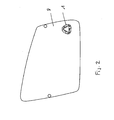
- FIG. 2 shows a schematic depiction in a top view of a light module according to the invention, which is integrated into a heating film;
- FIGS. 3 a and 3 b show a schematic depiction in a top view of a light module according to the invention, which is integrated into the edge area of a heating film;
- FIG. 4 shows the light module according to FIG. 3 , with an interface to the heating film
- FIG. 5 shows a schematic depiction in a side view of a light module integrated into a heating film according to another embodiment of the invention.
- the circuit carrier and the power supply circuit are made of the same material and configured in one piece, and they are formed by a flexible printed circuit board.
- the light module includes a circuit carrier and an interface leading to the power supply or to a control unit that are physically separate from each other. Since current connections to the circuit carrier itself are eliminated, fewer components are needed and the light module can be configured with a relatively small volume, so that it only takes up little installation space and is easy to mount. This also reduces the costs.
- the light sources are SIDE LEDs and/or TOP LEDs. They can emit white and/or colored light.
- the luminous surface can also be lit in several colors in order to generate the desired signals.
- the arrangement of the light sources on the circuit carrier can be adapted to the contour of the surface that is to be lit.
- At least one light-forming element can be provided.
- the light-forming element which has the function of directing the light coming from the light sources to the passenger compartment, can be formed, for example, by a simple optical waveguide. However, it is also conceivable to use other optical elements that can be used to influence the beam path of the light.
- the circuit carrier, the light sources, the optionally present additional electronic components and the light-forming element can have a flat, sandwich-like structure.
- the installation space needed is particularly small, the module is easy to handle and to accommodate.
- the light-forming element is arranged in such a manner that the circuit carrier with the light sources and the optionally present additional electronic components are sealed towards the outside.
- the electronic components are protected, for example, against the penetration of dust and other dirt, without additional components being needed for this purpose.
- the individual components can additionally be glued together.
- a diffuser especially a diffuser film, can be provided.
- masks can be provided to generate desired symbols in the surface that is to be lit.
- the flexible printed circuit board is configured as a strip-shaped printed conductor installed in the area of the power supply circuit.
- the circuit carrier can also be integrated into a flexible printed circuit board that serves to provide other extra functions such as, for example, a heating function and/or an antenna function or another light function.
- the power supply circuit or the contact to a control unit is established via the flexible printed circuit board.
- the circuit carrier only has to be positioned with the light sources in such a way that, once the light sources are mounted, they are visible in the rearview mirror through a signal window of the rearview mirror.
- the circuit carrier can also be arranged on the outer edge of the flexible printed circuit board in such a way that, during the mounting, it can be brought into the area of the signal display window of the rearview mirror by folding or bending the strip-shaped printed conductor over toward the inside.
- the light module can project, for example, towards the outside away from the edge of the flexible printed circuit board.
- the strip-shaped printed conductor can be configured in one piece and can be made of the same material as the flexible printed circuit board. However, it is also possible to provide an interface between the light module and the flexible printed circuit board.
- the circuit carrier with the light sources is positioned in such a way that, when in the mounted state, the light sources are visible through a signal display window of the rearview mirror.
- the flexible printed circuit board can have, for instance, an appropriate recess.
- the circuit carrier can be folded directly against the signal window. However, it can also be arranged at a distance, whereby the diffuser and the light-forming element can be provided in the area of the signal window.
- a light module according to an embodiment of the invention is preferably used to display signals in a rearview mirror of a motor vehicle. It can be arranged in the mirror glass surface as well as in the area of the mirror base.
- the blind spot is used to display the blind spot.
- it is by no means restricted to this type of display. There are no limitations when it comes to the application possibilities. In spite of its simple structure with the smallest possible number of components, any kind of symbols can be shown in any color.
- FIG. 1 A light module 1 according to a preferred embodiment of the invention can be seen in FIG. 1 .
- the light module 1 is configured as a separate component, without this constituting a restriction.
- FIG. 1 a shows the light module 1 in a top view.
- FIG. 1 b is a schematic depiction of the light distribution.
- FIG. 1 c shows a section of a cross sectional view of a light module 1 according to the invention.
- the light module 1 according to the invention is configured in the figure as a separate component, without this constituting a restriction.
- Three SIDE LEDs 4 i, 4 j , 4 k as well as additional electronic components 5 are arranged on a circuit carrier 2 having a power supply circuit 3 .
- the power supply circuit 3 serves to connect the circuit carrier 2 to an interface that is arranged at a distance from the circuit carrier and that leads to connection means to establish a connection to a source of current/voltage and/or to a control unit.
- the circuit carrier 2 and the power supply circuit 3 are made of the same material and configured in one piece, and they are formed by a flexible printed circuit board.
- the arrangement of the SIDE LEDs 4 i , 4 j, 4 k on the circuit carrier 2 is adapted to the contour of the surface that is to be lit, here a triangle, without this constituting a restriction.
- Figure lb) schematically shows the light cones 7 i , 7 j, 7 k emitted by the light sources.
- At least one optical waveguide 6 that, in the embodiment shown, completely fills the triangular surface between the SIDE LEDs 4 i, 4 j, 4 k and seals them as well as the circuit carrier 2 towards the outside. The penetration of dust and other dirt is thus effectively prevented.
- circuit carrier 2 the SIDE LEDs 4 i, 4 j, 4 k and the additional components 5 as well as the optical waveguide 6 have a flat, sandwich-like structure.
- the power supply circuit 3 is configured as a strip-shaped printed conductor (flex tail).
- FIG. 2 shows a surface heating film 8 whose outer contour is adapted to the outer contour of a mirror glass surface of a rearview mirror in order to heat said mirror glass surface.
- a surface heating film 8 in the present embodiment is only given by way of example. This could equally well be a flexible printed circuit board for an antenna function or some other light function or a cable set or another function.
- the light module or the circuit carrier 2 of the light module 1 is integrated into the heating film 8 .
- the circuit carrier 2 with the strip-shaped printed conductor 3 is likewise an integral part of the heating film 8 .
- the strip-shaped printed conductor 3 and the circuit carrier 2 extend towards the outside away from the edge of the heating film, so that the circuit carrier 2 can only be brought into the area of the signal display window of the rearview mirror by folding the strip-shaped printed conductor 3 over.
- the heating film 8 has a recess 9 in the area of the signal display window.
- FIG. 4 shows an interface 10 between the heating film and the strip-shaped printed conductor 3 with the circuit carrier 2 .
- the light module is configured as a separate component.
- FIG. 5 shows an embodiment of a light module 1 according to an embodiment of the invention in which the circuit carrier 2 with the light sources, here TOP LEDs 11 i , 11 j , 11 k , are integrated into the heating film 8 , but arranged at a distance from the signal display window of the rearview mirror.
- the optical elements i.e. the optical waveguide 6 and the diffuser film 12 , are arranged at a distance above the light sources.
Abstract
Description
- This application claims priority to German Patent Application No. DE 10 2010 048 801.1, filed Oct. 20, 2010, which is hereby incorporated by reference herein in its entirety.
- The invention relates to a light module to display a signal in the rearview mirror of a motor vehicle, comprising a circuit carrier on which at least one light source and, optionally, additional electronic components, are arranged, and a power supply circuit for connecting the circuit carrier to an interface that is arranged at a distance from the circuit carrier and that leads to connection means to establish a connection to a source of current/voltage and/or to a control unit.
- A light module for displaying a signal in a rearview mirror is described in international patent application WO 2004/024502 A1. The light module, which is arranged on the back of the mirror glass of a rearview mirror of a motor vehicle, consists of a rigid circuit board that is fitted with LEDs on the side facing the back of the mirror glass. This publication puts forward cables in order to connect the circuit board to a current/voltage supply or to a control unit. The LEDs serve to display differently lit symbols in the surface of the mirror glass in order to indicate special driving or ambient situations of the vehicle such as, for example, an activated turn signal, an approaching vehicle in the blind spot, etc.
- A drawback of the prior-art light module is that its structure is very complex and requires a great deal of installation space.
- An aspect of the present invention is to refine a light module of the above-mentioned type in such a way that it is easy and cost-effective to produce and takes up little installation space.
- In an embodiment, the present invention provides a light module for displaying a signal in a rearview mirror of a motor vehicle including a circuit carrier, at least one light source disposed on the circuit carrier and a power supply circuit. The power supply circuit is for connecting the circuit carrier to an interface that is disposed at a distance from the circuit carrier and that leads to at least one of a control unit and a current or voltage source. The power supply circuit and circuit carrier are made of the same material, are configured in one piece and are formed by a flexible printed circuit board.
- Embodiments of the present invention are described in the following with reference to the drawings, in which:
-
FIGS. 1 a, 1 b and 1 c show a schematic depiction of a light module according to a preferred embodiment of the invention in various views; -
FIG. 2 shows a schematic depiction in a top view of a light module according to the invention, which is integrated into a heating film; -
FIGS. 3 a and 3 b show a schematic depiction in a top view of a light module according to the invention, which is integrated into the edge area of a heating film; -
FIG. 4 shows the light module according toFIG. 3 , with an interface to the heating film; and -
FIG. 5 shows a schematic depiction in a side view of a light module integrated into a heating film according to another embodiment of the invention. - A light module according to an embodiment of the invention, for displaying a signal in the rearview mirror of a motor vehicle comprises a circuit carrier on which at least one light source and, optionally, additional electronic components are arranged, and a power supply circuit for connecting the circuit carrier to an interface that is arranged at a distance from the circuit carrier and that leads to connection means to establish a connection to a source of current/voltage and/or to a control unit. With a light module of the above-mentioned type, it is provided that the circuit carrier and the power supply circuit are made of the same material and configured in one piece, and they are formed by a flexible printed circuit board.
- In an embodiment, the light module includes a circuit carrier and an interface leading to the power supply or to a control unit that are physically separate from each other. Since current connections to the circuit carrier itself are eliminated, fewer components are needed and the light module can be configured with a relatively small volume, so that it only takes up little installation space and is easy to mount. This also reduces the costs.
- In a preferred embodiment of the invention, the light sources are SIDE LEDs and/or TOP LEDs. They can emit white and/or colored light. In particular, the luminous surface can also be lit in several colors in order to generate the desired signals.
- Advantageously, the arrangement of the light sources on the circuit carrier can be adapted to the contour of the surface that is to be lit.
- In order to set the radiation angle of the light, at least one light-forming element can be provided. The light-forming element, which has the function of directing the light coming from the light sources to the passenger compartment, can be formed, for example, by a simple optical waveguide. However, it is also conceivable to use other optical elements that can be used to influence the beam path of the light.
- Advantageously, the circuit carrier, the light sources, the optionally present additional electronic components and the light-forming element can have a flat, sandwich-like structure. In this embodiment, the installation space needed is particularly small, the module is easy to handle and to accommodate.
- In another preferred embodiment of the invention, the light-forming element is arranged in such a manner that the circuit carrier with the light sources and the optionally present additional electronic components are sealed towards the outside. In this manner, the electronic components are protected, for example, against the penetration of dust and other dirt, without additional components being needed for this purpose. The individual components can additionally be glued together.
- In order to uniformly illuminate the surface that is to be lit, in a generally known manner, a diffuser, especially a diffuser film, can be provided.
- By the same token, masks can be provided to generate desired symbols in the surface that is to be lit.
- According to another preferred embodiment of the invention, the flexible printed circuit board is configured as a strip-shaped printed conductor installed in the area of the power supply circuit.
- The circuit carrier can also be integrated into a flexible printed circuit board that serves to provide other extra functions such as, for example, a heating function and/or an antenna function or another light function. In this case, the power supply circuit or the contact to a control unit is established via the flexible printed circuit board. Here, the circuit carrier only has to be positioned with the light sources in such a way that, once the light sources are mounted, they are visible in the rearview mirror through a signal window of the rearview mirror.
- However, the circuit carrier can also be arranged on the outer edge of the flexible printed circuit board in such a way that, during the mounting, it can be brought into the area of the signal display window of the rearview mirror by folding or bending the strip-shaped printed conductor over toward the inside. For this purpose, the light module can project, for example, towards the outside away from the edge of the flexible printed circuit board. Here, the strip-shaped printed conductor can be configured in one piece and can be made of the same material as the flexible printed circuit board. However, it is also possible to provide an interface between the light module and the flexible printed circuit board.
- With this embodiment as well, the circuit carrier with the light sources is positioned in such a way that, when in the mounted state, the light sources are visible through a signal display window of the rearview mirror. For this purpose, the flexible printed circuit board can have, for instance, an appropriate recess. In the case of a sandwich-like structure, the circuit carrier can be folded directly against the signal window. However, it can also be arranged at a distance, whereby the diffuser and the light-forming element can be provided in the area of the signal window.
- A light module according to an embodiment of the invention is preferably used to display signals in a rearview mirror of a motor vehicle. It can be arranged in the mirror glass surface as well as in the area of the mirror base.
- Preferably, it is used to display the blind spot. However, it is by no means restricted to this type of display. There are no limitations when it comes to the application possibilities. In spite of its simple structure with the smallest possible number of components, any kind of symbols can be shown in any color.
- A
light module 1 according to a preferred embodiment of the invention can be seen inFIG. 1 . Thelight module 1 is configured as a separate component, without this constituting a restriction.FIG. 1 a) shows thelight module 1 in a top view.FIG. 1 b) is a schematic depiction of the light distribution.FIG. 1 c) shows a section of a cross sectional view of alight module 1 according to the invention. Thelight module 1 according to the invention is configured in the figure as a separate component, without this constituting a restriction. Three SIDE LEDs 4 i, 4 j, 4 k as well as additionalelectronic components 5 are arranged on acircuit carrier 2 having apower supply circuit 3. Thepower supply circuit 3 serves to connect thecircuit carrier 2 to an interface that is arranged at a distance from the circuit carrier and that leads to connection means to establish a connection to a source of current/voltage and/or to a control unit. - According to the invention, the
circuit carrier 2 and thepower supply circuit 3 are made of the same material and configured in one piece, and they are formed by a flexible printed circuit board. In the embodiment of the invention shown, the arrangement of the SIDE LEDs 4 i, 4 j, 4 k on thecircuit carrier 2 is adapted to the contour of the surface that is to be lit, here a triangle, without this constituting a restriction. Figure lb) schematically shows the light cones 7 i, 7 j, 7 k emitted by the light sources. In order to set the radiation angle of the light, there is at least oneoptical waveguide 6 that, in the embodiment shown, completely fills the triangular surface between the SIDE LEDs 4 i, 4 j, 4 k and seals them as well as thecircuit carrier 2 towards the outside. The penetration of dust and other dirt is thus effectively prevented. - In the figures, it can be seen that the
circuit carrier 2, the SIDE LEDs 4 i, 4 j, 4 k and theadditional components 5 as well as theoptical waveguide 6 have a flat, sandwich-like structure. - In the embodiment shown, the
power supply circuit 3 is configured as a strip-shaped printed conductor (flex tail). -
FIG. 2 shows asurface heating film 8 whose outer contour is adapted to the outer contour of a mirror glass surface of a rearview mirror in order to heat said mirror glass surface. However, the use of asurface heating film 8 in the present embodiment is only given by way of example. This could equally well be a flexible printed circuit board for an antenna function or some other light function or a cable set or another function. In this embodiment, the light module or thecircuit carrier 2 of thelight module 1 is integrated into theheating film 8. - In the embodiment of the invention shown in
FIG. 3 , thecircuit carrier 2 with the strip-shaped printedconductor 3 is likewise an integral part of theheating film 8. The strip-shaped printedconductor 3 and thecircuit carrier 2, however, extend towards the outside away from the edge of the heating film, so that thecircuit carrier 2 can only be brought into the area of the signal display window of the rearview mirror by folding the strip-shaped printedconductor 3 over. Theheating film 8 has arecess 9 in the area of the signal display window. -
FIG. 4 shows aninterface 10 between the heating film and the strip-shaped printedconductor 3 with thecircuit carrier 2. In this embodiment as well, the light module is configured as a separate component. -
FIG. 5 shows an embodiment of alight module 1 according to an embodiment of the invention in which thecircuit carrier 2 with the light sources, here TOP LEDs 11 i, 11 j, 11 k, are integrated into theheating film 8, but arranged at a distance from the signal display window of the rearview mirror. The optical elements, i.e. theoptical waveguide 6 and thediffuser film 12, are arranged at a distance above the light sources. - While the invention has been particularly shown and described with reference to preferred embodiments thereof, it will be understood by those skilled in the art that various changes in form and details may be made therein without departing from the spirit and scope of the invention.
Claims (19)
Applications Claiming Priority (3)
| Application Number | Priority Date | Filing Date | Title |
|---|---|---|---|
| DE102010048801.1 | 2010-10-20 | ||
| DE102010048801 | 2010-10-20 | ||
| DE102010048801A DE102010048801A1 (en) | 2010-10-20 | 2010-10-20 | light module |
Publications (2)
| Publication Number | Publication Date |
|---|---|
| US20120099335A1 true US20120099335A1 (en) | 2012-04-26 |
| US8794806B2 US8794806B2 (en) | 2014-08-05 |
Family
ID=45771672
Family Applications (1)
| Application Number | Title | Priority Date | Filing Date |
|---|---|---|---|
| US13/275,344 Expired - Fee Related US8794806B2 (en) | 2010-10-20 | 2011-10-18 | Light module |
Country Status (4)
| Country | Link |
|---|---|
| US (1) | US8794806B2 (en) |
| EP (1) | EP2444283B1 (en) |
| DE (1) | DE102010048801A1 (en) |
| ES (1) | ES2773934T3 (en) |
Cited By (5)
| Publication number | Priority date | Publication date | Assignee | Title |
|---|---|---|---|---|
| WO2016088115A3 (en) * | 2014-12-05 | 2016-08-04 | Smr Patents S.A.R.L. | Method for manufacturing an automotive mirror |
| US9434313B2 (en) | 2011-02-14 | 2016-09-06 | Gentex Corporation | Low profile optical lighting assembly for use in outside vehicle mirror and method of forming same |
| EP3854635A1 (en) * | 2020-01-21 | 2021-07-28 | Bayerische Motoren Werke Aktiengesellschaft | Rear view mirror for a two-wheeled vehicle |
| USRE49072E1 (en) * | 2014-08-29 | 2022-05-17 | Sl Mirrortech Corporation | Vehicle side mirror |
| US20220305982A1 (en) * | 2021-03-25 | 2022-09-29 | Motherson Innovations Company Limited | Light module, method for manufacturing a light module and rear view device |
Families Citing this family (5)
| Publication number | Priority date | Publication date | Assignee | Title |
|---|---|---|---|---|
| EP2783916A1 (en) * | 2013-03-28 | 2014-10-01 | SMR Patents S.à.r.l. | Circuit board, display device and exterior rear view mirror |
| DE102014005610A1 (en) * | 2014-04-09 | 2015-10-15 | Mekra Lang Gmbh & Co. Kg | Indicator unit for a device for indirect vision of a vehicle and device for indirect vision with a turn signal unit |
| EP2945465B1 (en) * | 2014-05-12 | 2019-12-25 | SMR Patents S.à.r.l. | Electronic circuit for a blind spot monitoring display and corresponding production method |
| US11117521B2 (en) | 2014-11-17 | 2021-09-14 | SMR Patents S.à.r.l. | Heater pad, heating and lighting unit, rear view assembly and rear view mirror device |
| KR102196640B1 (en) | 2016-07-22 | 2020-12-31 | 에스엠알 페턴츠 에스.에이.알.엘. | Heater pad, heating and lighting unit, glass assembly and rear view mirror device |
Citations (2)
| Publication number | Priority date | Publication date | Assignee | Title |
|---|---|---|---|---|
| US6657767B2 (en) * | 2001-05-21 | 2003-12-02 | Gentex Corporation | Rearview mirror assembly construction |
| US7513664B2 (en) * | 2004-05-10 | 2009-04-07 | Ichikoh Industries, Ltd. | Outside mirror apparatus including lighting device for vehicle |
Family Cites Families (5)
| Publication number | Priority date | Publication date | Assignee | Title |
|---|---|---|---|---|
| WO2004024502A2 (en) | 2002-09-12 | 2004-03-25 | Gentex Corporation | Rearview mirror assembly including a multi-functional light module |
| DE10327072A1 (en) * | 2003-06-13 | 2005-01-05 | Schefenacker Vision Systems Germany Gmbh & Co. Kg | Mirror glass assembly with integrated bulbs |
| US7293901B2 (en) * | 2004-03-09 | 2007-11-13 | Gentex Corporation | Optics for controlling the direction of light rays and assemblies incorporating the optics |
| US7717596B1 (en) * | 2005-07-15 | 2010-05-18 | Alan Bell | Rearview mirror assembly with running lights |
| US20070053179A1 (en) * | 2005-09-08 | 2007-03-08 | Pang Slew I | Low profile light source utilizing a flexible circuit carrier |
-
2010
- 2010-10-20 DE DE102010048801A patent/DE102010048801A1/en not_active Ceased
-
2011
- 2011-10-07 ES ES11008148T patent/ES2773934T3/en active Active
- 2011-10-07 EP EP11008148.6A patent/EP2444283B1/en active Active
- 2011-10-18 US US13/275,344 patent/US8794806B2/en not_active Expired - Fee Related
Patent Citations (2)
| Publication number | Priority date | Publication date | Assignee | Title |
|---|---|---|---|---|
| US6657767B2 (en) * | 2001-05-21 | 2003-12-02 | Gentex Corporation | Rearview mirror assembly construction |
| US7513664B2 (en) * | 2004-05-10 | 2009-04-07 | Ichikoh Industries, Ltd. | Outside mirror apparatus including lighting device for vehicle |
Cited By (8)
| Publication number | Priority date | Publication date | Assignee | Title |
|---|---|---|---|---|
| US9434313B2 (en) | 2011-02-14 | 2016-09-06 | Gentex Corporation | Low profile optical lighting assembly for use in outside vehicle mirror and method of forming same |
| USRE49072E1 (en) * | 2014-08-29 | 2022-05-17 | Sl Mirrortech Corporation | Vehicle side mirror |
| WO2016088115A3 (en) * | 2014-12-05 | 2016-08-04 | Smr Patents S.A.R.L. | Method for manufacturing an automotive mirror |
| US10457345B2 (en) | 2014-12-05 | 2019-10-29 | SMR Patents S.à.r.l. | Method for manufacturing an automotive mirror |
| EP3854635A1 (en) * | 2020-01-21 | 2021-07-28 | Bayerische Motoren Werke Aktiengesellschaft | Rear view mirror for a two-wheeled vehicle |
| US20220305982A1 (en) * | 2021-03-25 | 2022-09-29 | Motherson Innovations Company Limited | Light module, method for manufacturing a light module and rear view device |
| US11598493B2 (en) * | 2021-03-25 | 2023-03-07 | Motherson Innovations Company Limited | Light module, method for manufacturing a light module and rear view device |
| US11821592B2 (en) | 2021-03-25 | 2023-11-21 | Motherson Innovations Company Limited | Light module, method for manufacturing a light module and rear view device |
Also Published As
| Publication number | Publication date |
|---|---|
| EP2444283A3 (en) | 2018-04-11 |
| DE102010048801A1 (en) | 2012-04-26 |
| EP2444283A2 (en) | 2012-04-25 |
| US8794806B2 (en) | 2014-08-05 |
| ES2773934T3 (en) | 2020-07-15 |
| EP2444283B1 (en) | 2020-02-19 |
Similar Documents
| Publication | Publication Date | Title |
|---|---|---|
| US8794806B2 (en) | Light module | |
| US10415792B2 (en) | Light guiding device | |
| JP5961053B2 (en) | Vehicle rear panel | |
| US8469563B2 (en) | Turn-indicator light module for a vehicle mirror assembly and vehicle mirror assembly comprising a turn-indicator light module | |
| US8950914B2 (en) | Lighting unit | |
| US9796333B2 (en) | Sealed mirror head | |
| US20160341393A1 (en) | Light Guiding Device | |
| US20110013409A1 (en) | Light guide turn signal indicator rear view mirror | |
| US10173581B2 (en) | Turn signal unit for an external mirror | |
| US9688182B2 (en) | Vehicle lamp | |
| US7665869B2 (en) | Light for the passenger compartment of a motor vehicle | |
| US10562447B2 (en) | Interior lighting module for a motor vehicle | |
| EP1726480A2 (en) | Motor vehicle rear view mirror assembly comprising a flashing light-emitting device | |
| US20150283936A1 (en) | Vehicular lamp | |
| US20180170278A1 (en) | Display device for arrangement on a motor vehicle window | |
| KR100925570B1 (en) | Mirror glass component with integrated illuminating means | |
| EP3279036B1 (en) | Illumination device, method for producing the same and rearview device | |
| JP5397834B2 (en) | Instrument lighting device | |
| JP2013103701A (en) | Emblem for vehicle | |
| ZA200603638B (en) | Mirror glass component comprising an integrated luminous film | |
| US20160107567A1 (en) | Instrument cluster including a pcb mounted light conductor | |
| WO2016013415A1 (en) | Light-emitting device | |
| US10408424B2 (en) | Light guiding device | |
| JP2019059387A (en) | Lighting system and moving body | |
| US11175496B2 (en) | Display |
Legal Events
| Date | Code | Title | Description |
|---|---|---|---|
| AS | Assignment |
Owner name: CARL FREUDENBERG KG, GERMANY Free format text: ASSIGNMENT OF ASSIGNORS INTEREST;ASSIGNORS:BOEHLAND, HEIKO;RUNGE, OLAF;RENNER, GUIDO;SIGNING DATES FROM 20111010 TO 20111014;REEL/FRAME:027074/0899 |
|
| STCF | Information on status: patent grant |
Free format text: PATENTED CASE |
|
| AS | Assignment |
Owner name: MEKTEC EUROPE GMBH, GERMANY Free format text: ASSIGNMENT OF ASSIGNORS INTEREST;ASSIGNOR:CARL FREUDENBERG KG;REEL/FRAME:038240/0001 Effective date: 20160308 |
|
| MAFP | Maintenance fee payment |
Free format text: PAYMENT OF MAINTENANCE FEE, 4TH YEAR, LARGE ENTITY (ORIGINAL EVENT CODE: M1551) Year of fee payment: 4 |
|
| FEPP | Fee payment procedure |
Free format text: MAINTENANCE FEE REMINDER MAILED (ORIGINAL EVENT CODE: REM.); ENTITY STATUS OF PATENT OWNER: LARGE ENTITY |
|
| LAPS | Lapse for failure to pay maintenance fees |
Free format text: PATENT EXPIRED FOR FAILURE TO PAY MAINTENANCE FEES (ORIGINAL EVENT CODE: EXP.); ENTITY STATUS OF PATENT OWNER: LARGE ENTITY |
|
| STCH | Information on status: patent discontinuation |
Free format text: PATENT EXPIRED DUE TO NONPAYMENT OF MAINTENANCE FEES UNDER 37 CFR 1.362 |
|
| FP | Lapsed due to failure to pay maintenance fee |
Effective date: 20220805 |