US20110160836A1 - Valve device - Google Patents
Valve device Download PDFInfo
- Publication number
- US20110160836A1 US20110160836A1 US12/971,464 US97146410A US2011160836A1 US 20110160836 A1 US20110160836 A1 US 20110160836A1 US 97146410 A US97146410 A US 97146410A US 2011160836 A1 US2011160836 A1 US 2011160836A1
- Authority
- US
- United States
- Prior art keywords
- valve
- support structure
- support
- poly
- prosthesis
- Prior art date
- Legal status (The legal status is an assumption and is not a legal conclusion. Google has not performed a legal analysis and makes no representation as to the accuracy of the status listed.)
- Abandoned
Links
- 0 C.C.C.C.[1*][Si]([2*])(CCC(C)(C)C)O[Si]([3*])([4*])O[Si]([5*])([6*])C[Y]C(C)(C)C Chemical compound C.C.C.C.[1*][Si]([2*])(CCC(C)(C)C)O[Si]([3*])([4*])O[Si]([5*])([6*])C[Y]C(C)(C)C 0.000 description 6
- IMNIMPAHZVJRPE-UHFFFAOYSA-N C1CN2CCN1CC2 Chemical compound C1CN2CCN1CC2 IMNIMPAHZVJRPE-UHFFFAOYSA-N 0.000 description 1
- NSROHHMFZGBBMI-UHFFFAOYSA-N C=CCOCC(C)OCC(C)O.CC(O)COC(C)COCCC[Si](C)(C)O[Si](C)(C)O[Si](C)(C)CCCOCC(C)OCC(C)O.C[SiH](C)O[Si](C)(C)O[SiH](C)C Chemical compound C=CCOCC(C)OCC(C)O.CC(O)COC(C)COCCC[Si](C)(C)O[Si](C)(C)O[Si](C)(C)CCCOCC(C)OCC(C)O.C[SiH](C)O[Si](C)(C)O[SiH](C)C NSROHHMFZGBBMI-UHFFFAOYSA-N 0.000 description 1
- WLSNOVPTBMMJMS-UHFFFAOYSA-N C=CCOCC(C)OCC(C)O.CC(O)COC(C)COCCC[Si](C)(C)O[Si](C)(C)O[Si](C)(CCC(F)(F)F)O[Si](C)(C)O[Si](C)(C)CCCOCC(C)OCC(C)O.C[SiH](C)O[Si](C)(C)O[Si](C)(CCC(F)(F)F)O[Si](C)(C)O[SiH](C)C Chemical compound C=CCOCC(C)OCC(C)O.CC(O)COC(C)COCCC[Si](C)(C)O[Si](C)(C)O[Si](C)(CCC(F)(F)F)O[Si](C)(C)O[Si](C)(C)CCCOCC(C)OCC(C)O.C[SiH](C)O[Si](C)(C)O[Si](C)(CCC(F)(F)F)O[Si](C)(C)O[SiH](C)C WLSNOVPTBMMJMS-UHFFFAOYSA-N 0.000 description 1
- SYSGUVTVJUIJLB-UHFFFAOYSA-N CC(C)(C)CC1=CC=C(CO[Si](C)(C)O[Si](C)(C)O[Si](C)(C)OCC2=CC=C(CC(C)(C)C)C=C2)C=C1.CC(C)(C)CC1=CC=C(CO[Si](C)(C)O[Si](C)(CCC(F)(F)F)O[Si](C)(C)OCC2=CC=C(CC(C)(C)C)C=C2)C=C1.CC(COCCCO[Si](C)(C)O[Si](C)(C)O[Si](C)(C)CCCOCC(C)C(C)(C)C)C(C)(C)C.CC(COCCCO[Si](C)(C)O[Si](C)(CCC(F)(F)F)O[Si](C)(C)CCCOCC(C)C(C)(C)C)C(C)(C)C.CC(O)COC(C)COCCCO[Si](C)(C)O[Si](C)(C)O[Si](C)(C)CCCOCC(C)OCC(C)O.CC(O)COC(C)COCCC[Si](C)(C)O[Si](C)(C)O[Si](C)(CCC(F)(F)F)O[Si](C)(C)O[Si](C)(C)CCCOCC(C)OCC(C)O.CC(O)COCC1=CC=C(CO[Si](C)(C)O[Si](C)(CCC(F)(F)F)O[Si](C)(C)OCC2=CC=C(COCC(C)O)C=C2)C=C1.CC(O)COCCCO[Si](C)(C)O[Si](C)(CCC(F)(F)F)O[Si](C)(C)CCCOCC(C)O.CC(O)COCCC[Si](C)(C)O[Si](C)(C)O[Si](C)(CCC(F)(F)F)O[Si](C)(C)O[Si](C)(C)CCCOCC(C)O Chemical compound CC(C)(C)CC1=CC=C(CO[Si](C)(C)O[Si](C)(C)O[Si](C)(C)OCC2=CC=C(CC(C)(C)C)C=C2)C=C1.CC(C)(C)CC1=CC=C(CO[Si](C)(C)O[Si](C)(CCC(F)(F)F)O[Si](C)(C)OCC2=CC=C(CC(C)(C)C)C=C2)C=C1.CC(COCCCO[Si](C)(C)O[Si](C)(C)O[Si](C)(C)CCCOCC(C)C(C)(C)C)C(C)(C)C.CC(COCCCO[Si](C)(C)O[Si](C)(CCC(F)(F)F)O[Si](C)(C)CCCOCC(C)C(C)(C)C)C(C)(C)C.CC(O)COC(C)COCCCO[Si](C)(C)O[Si](C)(C)O[Si](C)(C)CCCOCC(C)OCC(C)O.CC(O)COC(C)COCCC[Si](C)(C)O[Si](C)(C)O[Si](C)(CCC(F)(F)F)O[Si](C)(C)O[Si](C)(C)CCCOCC(C)OCC(C)O.CC(O)COCC1=CC=C(CO[Si](C)(C)O[Si](C)(CCC(F)(F)F)O[Si](C)(C)OCC2=CC=C(COCC(C)O)C=C2)C=C1.CC(O)COCCCO[Si](C)(C)O[Si](C)(CCC(F)(F)F)O[Si](C)(C)CCCOCC(C)O.CC(O)COCCC[Si](C)(C)O[Si](C)(C)O[Si](C)(CCC(F)(F)F)O[Si](C)(C)O[Si](C)(C)CCCOCC(C)O SYSGUVTVJUIJLB-UHFFFAOYSA-N 0.000 description 1
- RJEHQKYVHRWNJW-UHFFFAOYSA-N CC(C)(C)N.CC(C)(C)N=C=O.CC(C)(C)N=C=O.CC(C)(C)NC(=O)NC(C)(C)C.CC(C)(C)NC(=O)OC(C)(C)C.CC(C)(C)O Chemical compound CC(C)(C)N.CC(C)(C)N=C=O.CC(C)(C)N=C=O.CC(C)(C)NC(=O)NC(C)(C)C.CC(C)(C)NC(=O)OC(C)(C)C.CC(C)(C)O RJEHQKYVHRWNJW-UHFFFAOYSA-N 0.000 description 1
- JDOPXZWDERGWLU-UHFFFAOYSA-K CC(C)C(=O)O[Bi](OC(=O)C(C)C)OC(=O)C(C)C.CCCCCC Chemical compound CC(C)C(=O)O[Bi](OC(=O)C(C)C)OC(=O)C(C)C.CCCCCC JDOPXZWDERGWLU-UHFFFAOYSA-K 0.000 description 1
- FDORQFRWHNEGAS-UHFFFAOYSA-N CC(COCCC[Si](C)(C)O[Si](C)(C)O[Si](C)(C)CCCOCC(C)C(C)(C)C)C(C)(C)C.CC(COCCC[Si](C)(C)O[Si](C)(CCC(F)(F)F)O[Si](C)(C)CCCOCC(C)C(C)(C)C)C(C)(C)C Chemical compound CC(COCCC[Si](C)(C)O[Si](C)(C)O[Si](C)(C)CCCOCC(C)C(C)(C)C)C(C)(C)C.CC(COCCC[Si](C)(C)O[Si](C)(CCC(F)(F)F)O[Si](C)(C)CCCOCC(C)C(C)(C)C)C(C)(C)C FDORQFRWHNEGAS-UHFFFAOYSA-N 0.000 description 1
- YLQUDYVHHCRJOA-UHFFFAOYSA-N CC(O)COCC1=CC=C(CO[Si](C)(C)O[Si](C)(C)O[Si](C)(C)OCC2=CC=C(COCC(C)O)C=C2)C=C1.C[Si](C)(O)O[Si](C)(C)O[Si](C)(C)O.C[Si](C)(OCC1=CC=C(CCl)C=C1)O[Si](C)(C)O[Si](C)(C)OCC1=CC=C(CCl)C=C1.ClCC1=CC=C(CCl)C=C1.[H]OCC(C)O Chemical compound CC(O)COCC1=CC=C(CO[Si](C)(C)O[Si](C)(C)O[Si](C)(C)OCC2=CC=C(COCC(C)O)C=C2)C=C1.C[Si](C)(O)O[Si](C)(C)O[Si](C)(C)O.C[Si](C)(OCC1=CC=C(CCl)C=C1)O[Si](C)(C)O[Si](C)(C)OCC1=CC=C(CCl)C=C1.ClCC1=CC=C(CCl)C=C1.[H]OCC(C)O YLQUDYVHHCRJOA-UHFFFAOYSA-N 0.000 description 1
- XVGZJPWPYNTKJI-UHFFFAOYSA-N CC(O)COCC1=CC=C(CO[Si](C)(C)O[Si](C)(CCC(F)(F)F)O[Si](C)(C)OCC2=CC=C(COCC(C)O)C=C2)C=C1.C[Si](C)(O)O[Si](C)(CCC(F)(F)F)O[Si](C)(C)O.C[Si](C)(OCC1=CC=C(CCl)C=C1)O[Si](C)(CCC(F)(F)F)O[Si](C)(C)OCC1=CC=C(CCl)C=C1.ClCC1=CC=C(CCl)C=C1.[H]OCC(C)O Chemical compound CC(O)COCC1=CC=C(CO[Si](C)(C)O[Si](C)(CCC(F)(F)F)O[Si](C)(C)OCC2=CC=C(COCC(C)O)C=C2)C=C1.C[Si](C)(O)O[Si](C)(CCC(F)(F)F)O[Si](C)(C)O.C[Si](C)(OCC1=CC=C(CCl)C=C1)O[Si](C)(CCC(F)(F)F)O[Si](C)(C)OCC1=CC=C(CCl)C=C1.ClCC1=CC=C(CCl)C=C1.[H]OCC(C)O XVGZJPWPYNTKJI-UHFFFAOYSA-N 0.000 description 1
- HTSIIFMQOCCPES-UHFFFAOYSA-N C[SiH](C)Cl.C[SiH](C)O[Si](C)(C)O[Si](C)(CCC(F)(F)F)O[Si](C)(C)O[SiH](C)C.C[Si](C)(O)O[Si](C)(CCC(F)(F)F)O[Si](C)(C)O Chemical compound C[SiH](C)Cl.C[SiH](C)O[Si](C)(C)O[Si](C)(CCC(F)(F)F)O[Si](C)(C)O[SiH](C)C.C[Si](C)(O)O[Si](C)(CCC(F)(F)F)O[Si](C)(C)O HTSIIFMQOCCPES-UHFFFAOYSA-N 0.000 description 1
- ZBCBWPMODOFKDW-UHFFFAOYSA-N [H]N(CCO)CCO Chemical compound [H]N(CCO)CCO ZBCBWPMODOFKDW-UHFFFAOYSA-N 0.000 description 1
Images


Classifications
-
- A—HUMAN NECESSITIES
- A61—MEDICAL OR VETERINARY SCIENCE; HYGIENE
- A61F—FILTERS IMPLANTABLE INTO BLOOD VESSELS; PROSTHESES; DEVICES PROVIDING PATENCY TO, OR PREVENTING COLLAPSING OF, TUBULAR STRUCTURES OF THE BODY, e.g. STENTS; ORTHOPAEDIC, NURSING OR CONTRACEPTIVE DEVICES; FOMENTATION; TREATMENT OR PROTECTION OF EYES OR EARS; BANDAGES, DRESSINGS OR ABSORBENT PADS; FIRST-AID KITS
- A61F2/00—Filters implantable into blood vessels; Prostheses, i.e. artificial substitutes or replacements for parts of the body; Appliances for connecting them with the body; Devices providing patency to, or preventing collapsing of, tubular structures of the body, e.g. stents
- A61F2/02—Prostheses implantable into the body
- A61F2/04—Hollow or tubular parts of organs, e.g. bladders, tracheae, bronchi or bile ducts
- A61F2/06—Blood vessels
-
- A—HUMAN NECESSITIES
- A61—MEDICAL OR VETERINARY SCIENCE; HYGIENE
- A61F—FILTERS IMPLANTABLE INTO BLOOD VESSELS; PROSTHESES; DEVICES PROVIDING PATENCY TO, OR PREVENTING COLLAPSING OF, TUBULAR STRUCTURES OF THE BODY, e.g. STENTS; ORTHOPAEDIC, NURSING OR CONTRACEPTIVE DEVICES; FOMENTATION; TREATMENT OR PROTECTION OF EYES OR EARS; BANDAGES, DRESSINGS OR ABSORBENT PADS; FIRST-AID KITS
- A61F2/00—Filters implantable into blood vessels; Prostheses, i.e. artificial substitutes or replacements for parts of the body; Appliances for connecting them with the body; Devices providing patency to, or preventing collapsing of, tubular structures of the body, e.g. stents
- A61F2/02—Prostheses implantable into the body
- A61F2/04—Hollow or tubular parts of organs, e.g. bladders, tracheae, bronchi or bile ducts
-
- A—HUMAN NECESSITIES
- A61—MEDICAL OR VETERINARY SCIENCE; HYGIENE
- A61F—FILTERS IMPLANTABLE INTO BLOOD VESSELS; PROSTHESES; DEVICES PROVIDING PATENCY TO, OR PREVENTING COLLAPSING OF, TUBULAR STRUCTURES OF THE BODY, e.g. STENTS; ORTHOPAEDIC, NURSING OR CONTRACEPTIVE DEVICES; FOMENTATION; TREATMENT OR PROTECTION OF EYES OR EARS; BANDAGES, DRESSINGS OR ABSORBENT PADS; FIRST-AID KITS
- A61F2/00—Filters implantable into blood vessels; Prostheses, i.e. artificial substitutes or replacements for parts of the body; Appliances for connecting them with the body; Devices providing patency to, or preventing collapsing of, tubular structures of the body, e.g. stents
- A61F2/82—Devices providing patency to, or preventing collapsing of, tubular structures of the body, e.g. stents
- A61F2/86—Stents in a form characterised by the wire-like elements; Stents in the form characterised by a net-like or mesh-like structure
- A61F2/90—Stents in a form characterised by the wire-like elements; Stents in the form characterised by a net-like or mesh-like structure characterised by a net-like or mesh-like structure
-
- A—HUMAN NECESSITIES
- A61—MEDICAL OR VETERINARY SCIENCE; HYGIENE
- A61F—FILTERS IMPLANTABLE INTO BLOOD VESSELS; PROSTHESES; DEVICES PROVIDING PATENCY TO, OR PREVENTING COLLAPSING OF, TUBULAR STRUCTURES OF THE BODY, e.g. STENTS; ORTHOPAEDIC, NURSING OR CONTRACEPTIVE DEVICES; FOMENTATION; TREATMENT OR PROTECTION OF EYES OR EARS; BANDAGES, DRESSINGS OR ABSORBENT PADS; FIRST-AID KITS
- A61F2/00—Filters implantable into blood vessels; Prostheses, i.e. artificial substitutes or replacements for parts of the body; Appliances for connecting them with the body; Devices providing patency to, or preventing collapsing of, tubular structures of the body, e.g. stents
- A61F2/95—Instruments specially adapted for placement or removal of stents or stent-grafts
-
- A—HUMAN NECESSITIES
- A61—MEDICAL OR VETERINARY SCIENCE; HYGIENE
- A61F—FILTERS IMPLANTABLE INTO BLOOD VESSELS; PROSTHESES; DEVICES PROVIDING PATENCY TO, OR PREVENTING COLLAPSING OF, TUBULAR STRUCTURES OF THE BODY, e.g. STENTS; ORTHOPAEDIC, NURSING OR CONTRACEPTIVE DEVICES; FOMENTATION; TREATMENT OR PROTECTION OF EYES OR EARS; BANDAGES, DRESSINGS OR ABSORBENT PADS; FIRST-AID KITS
- A61F2/00—Filters implantable into blood vessels; Prostheses, i.e. artificial substitutes or replacements for parts of the body; Appliances for connecting them with the body; Devices providing patency to, or preventing collapsing of, tubular structures of the body, e.g. stents
- A61F2/02—Prostheses implantable into the body
- A61F2/24—Heart valves ; Vascular valves, e.g. venous valves; Heart implants, e.g. passive devices for improving the function of the native valve or the heart muscle; Transmyocardial revascularisation [TMR] devices; Valves implantable in the body
- A61F2/2412—Heart valves ; Vascular valves, e.g. venous valves; Heart implants, e.g. passive devices for improving the function of the native valve or the heart muscle; Transmyocardial revascularisation [TMR] devices; Valves implantable in the body with soft flexible valve members, e.g. tissue valves shaped like natural valves
- A61F2/2418—Scaffolds therefor, e.g. support stents
-
- A—HUMAN NECESSITIES
- A61—MEDICAL OR VETERINARY SCIENCE; HYGIENE
- A61F—FILTERS IMPLANTABLE INTO BLOOD VESSELS; PROSTHESES; DEVICES PROVIDING PATENCY TO, OR PREVENTING COLLAPSING OF, TUBULAR STRUCTURES OF THE BODY, e.g. STENTS; ORTHOPAEDIC, NURSING OR CONTRACEPTIVE DEVICES; FOMENTATION; TREATMENT OR PROTECTION OF EYES OR EARS; BANDAGES, DRESSINGS OR ABSORBENT PADS; FIRST-AID KITS
- A61F2/00—Filters implantable into blood vessels; Prostheses, i.e. artificial substitutes or replacements for parts of the body; Appliances for connecting them with the body; Devices providing patency to, or preventing collapsing of, tubular structures of the body, e.g. stents
- A61F2/82—Devices providing patency to, or preventing collapsing of, tubular structures of the body, e.g. stents
- A61F2/848—Devices providing patency to, or preventing collapsing of, tubular structures of the body, e.g. stents having means for fixation to the vessel wall, e.g. barbs
-
- A—HUMAN NECESSITIES
- A61—MEDICAL OR VETERINARY SCIENCE; HYGIENE
- A61F—FILTERS IMPLANTABLE INTO BLOOD VESSELS; PROSTHESES; DEVICES PROVIDING PATENCY TO, OR PREVENTING COLLAPSING OF, TUBULAR STRUCTURES OF THE BODY, e.g. STENTS; ORTHOPAEDIC, NURSING OR CONTRACEPTIVE DEVICES; FOMENTATION; TREATMENT OR PROTECTION OF EYES OR EARS; BANDAGES, DRESSINGS OR ABSORBENT PADS; FIRST-AID KITS
- A61F2/00—Filters implantable into blood vessels; Prostheses, i.e. artificial substitutes or replacements for parts of the body; Appliances for connecting them with the body; Devices providing patency to, or preventing collapsing of, tubular structures of the body, e.g. stents
- A61F2/82—Devices providing patency to, or preventing collapsing of, tubular structures of the body, e.g. stents
- A61F2/852—Two or more distinct overlapping stents
-
- A—HUMAN NECESSITIES
- A61—MEDICAL OR VETERINARY SCIENCE; HYGIENE
- A61F—FILTERS IMPLANTABLE INTO BLOOD VESSELS; PROSTHESES; DEVICES PROVIDING PATENCY TO, OR PREVENTING COLLAPSING OF, TUBULAR STRUCTURES OF THE BODY, e.g. STENTS; ORTHOPAEDIC, NURSING OR CONTRACEPTIVE DEVICES; FOMENTATION; TREATMENT OR PROTECTION OF EYES OR EARS; BANDAGES, DRESSINGS OR ABSORBENT PADS; FIRST-AID KITS
- A61F2/00—Filters implantable into blood vessels; Prostheses, i.e. artificial substitutes or replacements for parts of the body; Appliances for connecting them with the body; Devices providing patency to, or preventing collapsing of, tubular structures of the body, e.g. stents
- A61F2/02—Prostheses implantable into the body
- A61F2/04—Hollow or tubular parts of organs, e.g. bladders, tracheae, bronchi or bile ducts
- A61F2002/044—Oesophagi or esophagi or gullets
-
- A—HUMAN NECESSITIES
- A61—MEDICAL OR VETERINARY SCIENCE; HYGIENE
- A61F—FILTERS IMPLANTABLE INTO BLOOD VESSELS; PROSTHESES; DEVICES PROVIDING PATENCY TO, OR PREVENTING COLLAPSING OF, TUBULAR STRUCTURES OF THE BODY, e.g. STENTS; ORTHOPAEDIC, NURSING OR CONTRACEPTIVE DEVICES; FOMENTATION; TREATMENT OR PROTECTION OF EYES OR EARS; BANDAGES, DRESSINGS OR ABSORBENT PADS; FIRST-AID KITS
- A61F2/00—Filters implantable into blood vessels; Prostheses, i.e. artificial substitutes or replacements for parts of the body; Appliances for connecting them with the body; Devices providing patency to, or preventing collapsing of, tubular structures of the body, e.g. stents
- A61F2/95—Instruments specially adapted for placement or removal of stents or stent-grafts
- A61F2002/9505—Instruments specially adapted for placement or removal of stents or stent-grafts having retaining means other than an outer sleeve, e.g. male-female connector between stent and instrument
- A61F2002/9511—Instruments specially adapted for placement or removal of stents or stent-grafts having retaining means other than an outer sleeve, e.g. male-female connector between stent and instrument the retaining means being filaments or wires
-
- A—HUMAN NECESSITIES
- A61—MEDICAL OR VETERINARY SCIENCE; HYGIENE
- A61F—FILTERS IMPLANTABLE INTO BLOOD VESSELS; PROSTHESES; DEVICES PROVIDING PATENCY TO, OR PREVENTING COLLAPSING OF, TUBULAR STRUCTURES OF THE BODY, e.g. STENTS; ORTHOPAEDIC, NURSING OR CONTRACEPTIVE DEVICES; FOMENTATION; TREATMENT OR PROTECTION OF EYES OR EARS; BANDAGES, DRESSINGS OR ABSORBENT PADS; FIRST-AID KITS
- A61F2220/00—Fixations or connections for prostheses classified in groups A61F2/00 - A61F2/26 or A61F2/82 or A61F9/00 or A61F11/00 or subgroups thereof
- A61F2220/0025—Connections or couplings between prosthetic parts, e.g. between modular parts; Connecting elements
- A61F2220/0033—Connections or couplings between prosthetic parts, e.g. between modular parts; Connecting elements made by longitudinally pushing a protrusion into a complementary-shaped recess, e.g. held by friction fit
-
- A—HUMAN NECESSITIES
- A61—MEDICAL OR VETERINARY SCIENCE; HYGIENE
- A61F—FILTERS IMPLANTABLE INTO BLOOD VESSELS; PROSTHESES; DEVICES PROVIDING PATENCY TO, OR PREVENTING COLLAPSING OF, TUBULAR STRUCTURES OF THE BODY, e.g. STENTS; ORTHOPAEDIC, NURSING OR CONTRACEPTIVE DEVICES; FOMENTATION; TREATMENT OR PROTECTION OF EYES OR EARS; BANDAGES, DRESSINGS OR ABSORBENT PADS; FIRST-AID KITS
- A61F2220/00—Fixations or connections for prostheses classified in groups A61F2/00 - A61F2/26 or A61F2/82 or A61F9/00 or A61F11/00 or subgroups thereof
- A61F2220/0025—Connections or couplings between prosthetic parts, e.g. between modular parts; Connecting elements
- A61F2220/0075—Connections or couplings between prosthetic parts, e.g. between modular parts; Connecting elements sutured, ligatured or stitched, retained or tied with a rope, string, thread, wire or cable
-
- A—HUMAN NECESSITIES
- A61—MEDICAL OR VETERINARY SCIENCE; HYGIENE
- A61F—FILTERS IMPLANTABLE INTO BLOOD VESSELS; PROSTHESES; DEVICES PROVIDING PATENCY TO, OR PREVENTING COLLAPSING OF, TUBULAR STRUCTURES OF THE BODY, e.g. STENTS; ORTHOPAEDIC, NURSING OR CONTRACEPTIVE DEVICES; FOMENTATION; TREATMENT OR PROTECTION OF EYES OR EARS; BANDAGES, DRESSINGS OR ABSORBENT PADS; FIRST-AID KITS
- A61F2230/00—Geometry of prostheses classified in groups A61F2/00 - A61F2/26 or A61F2/82 or A61F9/00 or A61F11/00 or subgroups thereof
- A61F2230/0002—Two-dimensional shapes, e.g. cross-sections
- A61F2230/0028—Shapes in the form of latin or greek characters
- A61F2230/0054—V-shaped
Definitions
- An esophageal stent is often placed across the lower esophageal sphincter (LES) to treat benign strictures or malignant obstructions.
- LES esophageal sphincter
- the consequent loss of a reflux barrier often results in significant amounts of acid reflux, which can reduce the quality of life of an already sick patient.
- Such esophageal stents that are placed across the gastric cardia are sometimes equipped with a flexible sleeve that hangs below the stent into the stomach.
- These so called ‘windsock’ devices rely on the slightly increased pressure of the stomach to flatten and close the sleeve.
- an esophageal valve having:—
- the valve comprises a polymeric valve body having an outer support rim, at least three valve leaflets, and a main body region extending between the support rim and the valve leaflets.
- the invention also provided a luminal valve for placing in a body lumen comprising at least four valve leaflets, the valve having a normally closed configuration in which the leaflets are engaged and an open configuration in which the leaflets are open. There may be at least five valve leaflets. There may be six valve leaflets.
- valve is an esophageal valve.
- valve has an antegrade open configuration in which the valve leaflets are opened in response to an antegrade force to allow flow through the valve and a retrograde open configuration in response to a retrograde force which is substantially larger than the antegrade force.
- the valve may comprise a valve body of polymeric material.
- the valve may comprise an outer support region.
- the valve may also have a main body region extending between the support region and the valve leaflets.
- the main body region is generally concave between the outer support rim and a region of co-aption of the valve leaflets.
- valve leaflets and at least portion of the main body region inverts to allow flow in the retrograde direction.
- the main valve region and the valve leaflets Preferably, on reduction in retrograde forces the main valve region and the valve leaflets evert to the normally closed configuration.
- valve leaflets have a region of co-aption and the valve body is reinforced at the region of co-aption.
- the valve body may be thickened at the region of co-aption.
- the region of co-aption may extend for an axial length of at least 1 mm.
- the region of co-aption may extend for a depth of from 1 mm to 5 mm.
- the support rim of the valve body is reinforced.
- the support rim of the valve may be thickened.
- the valve comprises three valve leaflets.
- valve comprises six valve leaflets.
- the invention also provides an esophageal valve comprising a support structure for the valve.
- the valve may be mounted to the support structure.
- valve rim is sutured to the support structure.
- valve rim is bonded to the support structure.
- the support structure comprises a luminal prosthesis.
- the luminal prosthesis extends proximally of the valve.
- the luminal prosthesis extends distally of the valve.
- the luminal prosthesis extends proximally and distally of the valve.
- the luminal prosthesis may have a coating and/or a sleeve thereon.
- the coating or sleeve may be on the outside of the luminal prosthesis.
- the coating or sleeve is on the inside of the luminal prosthesis.
- a pressure of 0.7 mm Hg in the antegrade direction is sufficient to allow a flowrate of 140 ml/min.
- the retrograde force required to open the valve is a pressure of greater than 15 mm Hg and less than 40 mm Hg.
- the polymeric material is stable to gastric fluid for at least 3 months, for at least 4 months, for at least 5 months, for at least 6 months, for at least 7 months, for at least 8 months, for at least 9 months, for at least 10 months, for at least 11 months, or for at least one year.
- the polymeric material takes up less than about 5%, less than about 10%, less than about 15%, less than about 20%, less than about 25%, or less than about 30% by weight of water at equilibrium.
- the polymeric material of the valve body has a % elongation of from 50% to 3000% or 200% to 1200%.
- the polymeric material of the valve body has a tensile strength of from 0.01 to 5 MPa or about 0.1 to 1.0 MPa, or about 0.25 to 0.5 MPa.
- the polymeric material has a Young's Modulus of about 0.01 to 0.6 MPa, or about 0.1 to about 0.5 MPa.
- the polymeric material of the valve body has a density of from 0.1 g/cm 3 to 1.5 g/cm 3 , or 0.3 to 1.2 g/cm 3 , or 0.8 to 0.9 g/cm 3 , or 0.5 to 0.6 g/cm 3 .
- the distance between the proximal end of the support region of the valve body and the distal end of the valve leaflets is less than 50 mm, or less than 40 mm, or less than 30 mm, or less than 25 mm, or less than 20 mm, or less than 15 mm.
- the polymeric material of the valve body is of an elastic material.
- the polymeric material of the valve body is of a viscoelastic material.
- the polymeric material of the valve body comprises a foam.
- the polymeric material of the valve body may comprise an open cell foam.
- the polymeric material of the valve body comprises a polyurethane foam.
- the esophageal valve is adapted to be mounted to a pre-deployed support structure, for example an esophageal luminal prosthesis such as a stent.
- the invention also provides a valve having:—
- valve is an esophageal valve for mounting to an esophageal stent.
- valve support region is sutured to the support structure.
- the valve support region may be bonded to the support structure.
- the luminal prosthesis may extend proximally of the valve.
- the luminal prosthesis may extend distally of the valve.
- the luminal prosthesis may extend proximally and distally of the valve.
- the luminal prosthesis has a coating and/or sleeve thereon.
- the coating or sleeve may be on the outside of the luminal prosthesis.
- the coating or sleeve is on the inside of the luminal prosthesis.
- valve is adapted to be mounted to a pre-deployed esophageal luminal prosthesis such as an esophageal stent.
- the valve may be a mounting means for mounting the valve to a pre-deployed esophageal luminal prosthesis.
- the mounting means may be provided on the valve.
- the mounting means comprises engagement means for engagement with a pre-deployed stent.
- the valve may comprise a support structure.
- the support structure may taper outwardly or inwardly.
- the support structure is of generally uniform diameter along the length hereof.
- the support structure comprises a scaffold.
- the support structure may comprise a stent-like structure.
- the mounting means may be provided by the support structure.
- the mounting means comprises protrusions extending from the support structure.
- the protrusions may be adapted to engage with a pre-deployed host esophageal luminal prosthesis.
- the protrusion comprises a loop.
- the apicial tip of the protrusion is rounded.
- the protrusions may be releasably engagable with a pre-deployed host esophageal luminal prosthesis.
- the release means may comprise means for reducing the diameter of at least portion of the valve support structure.
- the release means comprises a drawstring extending around the valve support structure.
- a first drawstring may extend around a proximal end of the support structure.
- a second drawstring may extend around a distal end of the support structure.
- valve is mounted to the support structure.
- the valve may be sutured to the support structure.
- the valve may be bonded to the support structure.
- the valve may be adhesively bonded to the support structure.
- the mounting means comprises a surgical adhesive.
- the invention also provides a method for providing a valve in a body passageway comprising the steps of:—
- the step of deploying the valve comprises engaging the valve support with the pre-deployed luminal prosthesis.
- the valve support may be mechanically engaged with the pre-deployed luminal prosthesis.
- valve support comprises a protrusion and the method comprises aligning the protrusion with an aperture in the endoluminal prosthesis and engaging the protrusion in the aperture.
- valve support is an expandable support and the method comprises loading the support onto a delivery catheter in a retracted form and the valve support is extendable on deployment.
- the support may be self expandable or the support is expanded by an expanding means such as a balloon.
- the method comprises the step of releasing the valve support from engagement with the luminal prosthesis.
- the method may involve repositioning the valve support within the prosthesis.
- the method may comprise removing the valve from the prosthesis.
- the body passageway is the esophagus and the valve is an esophageal valve for mounting to a pre-deployed esophageal stent.
- valve there is a support structure for the valve.
- the valve may be mounted to the support structure.
- the valve support region may be sutured to the support structure.
- valve support region is bonded to the support structure.
- support structure is overmoulded to the valve support region.
- the support structure may comprise a luminal prosthesis.
- the luminal prosthesis extends proximally of the valve.
- the prosthesis may comprise a self expanding plastics mesh.
- the prosthesis may apply a radial force of less than 1.9 kPa.
- anchors for mounting the prosthesis in situ.
- the anchors may be adapted to extend through the mesh of the prosthesis.
- the prosthesis is adapted to be anchored to the cardia.
- the length of the valve from the proximal end of the support region to the distal end of the valve leaflets is less than 50 mm, less than 40 mm, less than 30 mm.
- the length of the valve may be approximately the same as the outer diameter of the support region of the valve.
- the length of the valve may be approximately 23 mm.
- the invention comprises a method for treating gastroesophageal reflux disease comprising providing a valve of the invention and placing the valve at a desired location.
- the desired location may be across the lower esophageal sphincter.
- the valve leaflets are located distal to the end of the esophagus.
- the valve is provided with a support structure and the method comprises mounting the support structure at the desired location.
- the method may comprise anchoring the support structure to the body wall at the desired location.
- the method comprises anchoring the support structure to the cardia.
- FIG. 1 is an isometric view (from above) of an esophageal valve according to the invention
- FIG. 2 is an isometric view (from below) of the esophageal valve
- FIG. 3 is a top plan view of the valve
- FIG. 4 is an underneath plan view of the valve
- FIGS. 5 and 6 are elevational views of the valve
- FIGS. 7 and 8 are isometric, partially cut-away sectional, views of the valve
- FIGS. 9 and 10 are cross sectional views of the valve
- FIG. 11 is a cross sectional view of the valve in a normally closed configuration with an antegrade force applied
- FIG. 12 is a cross sectional view of the valve in an open configuration in response to an antegrade force
- FIG. 13 is a cross sectional view of the valve returned to the closed configuration after opening to antegrade flow
- FIG. 14 is a cross sectional view of the valve in a normally closed configuration with a retrograde force applied
- FIG. 15 is a cross sectional view of the valve in an open configuration in response to retrograde force
- FIG. 16 is a cross sectional view of the valve returned to the closed configuration after opening to retrograde flow
- FIG. 17 is an isometric view (from above) of the valve in a normally closed configuration
- FIG. 18 is an isometric view of the valve in a partially open configuration in response to an antegrade force
- FIG. 19 is an isometric view of the valve in a fully open configuration in response to antegrade force
- FIG. 20 is an isometric view (from below) of the valve in a normally closed configuration
- FIG. 21 is an isometric view of the valve moving towards an open configuration in response to a retrograde force
- FIG. 22 is an isometric view of the valve in a fully open configuration permitting retrograde flow
- FIG. 23 is an isometric view of a esophageal prosthesis
- FIG. 24 is an elevational view of the valve of FIGS. 1 to 22 being mounted to and in position on the prosthesis of FIG. 23 ;
- FIG. 25 is another view of the valve mounted in a prosthesis
- FIGS. 26 and 27 are isometric views of a sleeved or coated esophageal prosthesis
- FIG. 28 is an isometric view of the prosthesis of FIGS. 26 and 27 with a valve of FIGS. 1 to 22 in position;
- FIG. 29 is an elevational view of part of the prosthesis of FIG. 28 in position in the esophagus;
- FIG. 30 is an isometric view of a valve according to another embodiment of the invention.
- FIG. 31 is an elevational view of the valve of FIG. 30 ;
- FIG. 32 is an isometric view of another valve according to the invention with a distally outward tapering support structure
- FIG. 33 is an elevational view of the valve of FIG. 32 .
- FIG. 34 is an isometric view of another valve according to the invention with a distally inward tapering support structure
- FIG. 35 is an elevational view of a luminal prosthesis with a valve and associated support structure in place
- FIG. 36 is an enlarged view of the luminal prosthesis and valve support structure of FIG. 35 ;
- FIGS. 37 and 38 are enlarged views of one mounting detail of a valve support structure to a luminal prosthesis
- FIGS. 39 to 43 are views of a valve being deployed from a delivery catheter
- FIGS. 44 to 46 are views of a luminal prosthesis in place in the esophagus with a valve being deployed in the lumen of the luminal prosthesis.
- FIG. 47 is an elevational view of a valve according to another embodiment of the invention.
- FIG. 48 is an enlarged view of a detail of the support structure of the valve of FIG. 47 ;
- FIGS. 49 and 50 are isometric views of the valve of FIGS. 47 and 48 being deployed from a delivery catheter;
- FIG. 51 is an elevational view of a prosthesis with the valve of FIGS. 49 to 50 in situ;
- FIG. 52 is an enlarged view of a detail of the engagement of the valve support structure of FIGS. 47 to 51 engaged in the mesh of the prosthesis;
- FIG. 53 is an enlarged view of part of the luminal prosthesis and valve support structure of FIG. 52 .
- FIG. 54 is an elevational view of an esophageal luminal prosthesis
- FIG. 55 is an elevational of an esophageal valve of the invention.
- FIGS. 56 to 61 are elevational views of steps involved in deploying the valve of FIG. 55 into a pre-deployed esophageal luminal prosthesis of FIG. 54 ;
- FIG. 62 is an elevational view of the valve of FIG. 55 deployed in the luminal prosthesis of FIG. 61 ;
- FIG. 63 A is an elevational view similar to FIG. 62 with the valve being removed from the deployed prosthesis;
- FIG. 63 B is an elevational view of another luminal prosthesis according to the invention with a valve mounted therein;
- FIG. 63 C is a cross sectional view of the prosthesis and valve of FIG. 63 B;
- FIG. 63 D is an elevational view of a further luminal prosthesis according to the invention with a valve mounted therein;
- FIG. 63 E is a cross sectional view of the prosthesis and valve of FIG. 63 D;
- FIGS. 64 and 65 are isometric view of another valve according to the invention.
- FIG. 66 is a top plan view of the valve of FIGS. 64 and 65 ;
- FIG. 67 is an underneath plan view of the valve of FIGS. 64 and 65 ;
- FIG. 68 is an elevational view of the valve of FIGS. 64 and 65 ;
- FIG. 69 is a cross sectional view of the valve of FIGS. 64 and 65 ;
- FIG. 70 is a cut-away isometric view of the valve of FIGS. 64 and 65 ;
- FIG. 71 is an isometric view of a valve and an associated support
- FIG. 72 is an elevational view of the valve and support of FIG. 71 ;
- FIG. 73 is a plan view of the device of FIGS. 71 and 72 with the valve in a closed configuration
- FIG. 74 is a plan view similar to FIG. 73 with the valve in an open configuration
- FIGS. 75 and 76 are side views of the device of FIG. 73 with the valve in a closed configuration
- FIGS. 77 and 78 are side views of the device of FIG. 73 with the valve in the open configuration
- FIG. 79 is a cross sectional view of the device of FIG. 72 in use in a closed configuration
- FIG. 80 is a view similar to FIG. 79 with the device anchored at the desired location;
- FIG. 81 is a cross sectional view of the device in a closed configuration
- FIG. 82 is a cross sectional view of the device with the valve in the retrograde open configuration
- FIG. 83 is an elevational view of another device similar to FIG. 71 ;
- FIG. 84 is a plan view of the device of FIG. 83 ;
- FIG. 85 is an illustration of prior art polymers with urea and urethane linkages interspersed between homopolymer soft segments
- FIG. 86 is an illustration of a polyurethane/urea foam according to the invention with urea and urethane linkages interspersed between triblock copolymer soft segments;
- FIG. 87 is an illustration of a siloxane and polypropylene oxide based triblock copolymer in different forms
- FIG. 88 is a graph of comparative mechanical properties of homo (VF130309) and triblock copolymer (VF230209A) soft segments;
- FIG. 89 is a graph of comparative mechanical properties of home (VF190309) and triblock copolymer (VF090309) soft segments;
- FIG. 90 is a graph illustrating the mechanical performance of triblock copolymer soft segments versus homopolymer soft segment during accelerated aging in simulated gastric fluid
- FIG. 91 depicts a gastric yield pressure test apparatus as utilized in Example 10.
- FIG. 92A and FIG. 92B depict results of accelerated stability of a valve prepared from a viscoelastic foam of the present invention.
- FIGS. 1 to 22 there is illustrated an esophageal valve 1 which can open automatically in the antegrade direction (food intake) and in the retrograde direction (from the stomach to the mouth).
- the valve 1 comprises a polymeric valve body having a proximal outer support region with a rim 2 , at least three valve leaflets 3 , 4 , 5 , and a main body region 6 extending between the support rim 2 and the valve leaflets 3 , 4 , 5 .
- the valve leaflets 3 , 4 , 5 extend inwardly and distally and terminate at distal end faces 7 , 8 , 9 respectively.
- the leaflets each 3 , 4 , 5 have legs a, b which extend at an included angle of 120° to each other.
- the adjacent pairs of legs 3 a ; 4 a ; 4 b ; 5 b ; 5 a ; 3 b co-apt to close the gap between the valve leaflets when the valve is in the normally closed configuration.
- the valve 1 has three configurations.
- the first configuration is a normally closed configuration in which the valve leaflets 3 , 4 , 5 co-apt to close the valve.
- the second configuration is an antegrade open configuration in which the valve leaflets 3 , 4 , 5 are opened such that the leaflet leg pairs 3 a ; 4 a ; 4 b ; 5 b ; 5 a ; 3 b are opened and spaced-apart in response to an antegrade force F 1 to allow flow through the valve.
- the third configuration is a retrograde open configuration in response to a retrograde force which is substantially larger than the antegrade force F 2 .
- FIGS. 11 to 22 The various configurations of the valve 1 are illustrated in FIGS. 11 to 22 .
- the valve leaflets 3 , 4 , 5 co-apt.
- an antegrade force F 1 is applied to the valve leaflets 3 , 4 , 5 the leaflet legs pairs 3 a ; 4 a ; 4 b ; 5 b ; and 5 a ; 3 b open to allow antegrade flow to pass ( FIGS. 12 , 19 ).
- FIG. 18 illustrates a partially open configuration in response to antegrade flow.
- the leaflets 3 , 4 , 5 return to the closed position under the inherent biasing of the polymeric material of the valve body ( FIG. 13 ).
- a retrograde force F 2 When a retrograde force F 2 is applied to the valve body. This force initially pushes the valve leaflets 3 , 4 , 5 against one another and if the pressure is greater than a set value, the valve body will invert. The start of inversion is illustrated in FIG. 21 .
- the valve main body When the valve is fully opened in response to retrograde force the valve main body (and the leaflets 3 , 4 , 5 ) extend proximally (upwardly) as illustrated in FIGS. 15 and 22 . This allows retrograde flow to pass through the valve.
- the retrograde force F 2 When the retrograde force F 2 is removed the valve main body will return to the original configuration by everting in response to the biasing of the polymeric material to return to the normally closed configuration with the valve leaflets extending distally as illustrated in FIGS. 16 and 20 .
- valve leaflets 3 , 4 , 5 are reinforced in the region of co-aption. In this case, this is achieved by a local thickening of the polymeric material in this region. Similarly the support rim 2 is reinforced by a local thickening of the polymeric material.
- the region of co-aption of the valve leaflets 3 , 4 , 5 has an axial extent which is typically from 1 to 5 mm. This ensures positive co-aption of the leaflets across a significant interfacial area when the valve is in the normally closed configuration.
- the thickness of the leaflets at the region of co-aption is typically between 0.1 mm and 10 mm.
- the valve body has a generally concave outer face and a generally convex inner face.
- the valve 1 is a two-way valve. Different forces are required to open the valve from the proximal or distal directions.
- the valve 1 requires very little force to open in the antegrade direction, a pressure of 0.7 mm Hg in the antegrade direction is sufficient to allow a flowrate of 140 ml/min.
- the valve 1 can hold pressures of between 15 mmHg and 40 mmHg and higher.
- the valve accomplishes this by controllably inverting when placed under pressure in the retrograde direction.
- the valve 1 of the invention returns to its original working position after being fully opened in the retrograde direction. This is accomplished without damaging the working valve.
- valve When the valve is opened by food passing in the antegrade direction the leaflets open.
- the outer face of the valve has a greater resistance to change in shape and thus the force required to open main body in the retrograde direction is higher.
- valve 1 The important characteristics influencing the functioning of the valve are the leaflet legs that impinge on one another.
- the valve 1 can be made to open in the retrograde direction at different pressures. Opening in the antegrade direction is somewhat less dependant on the geometry of the leaflets and more dependant on the elasticity and density of the material the device is made from. Additionally, the overall diameter and the diameter to which the leaflets open influence the opening force in both directions.
- the current invention teaches a method of retaining the short length of the valve structure and maximising the force generated by the gastric pressure through an increase in the surface area to length ratio. This is achieved by increasing the surface area of the distal surface of the valve by introducing pleats or folds (leaflets).
- the valve may be of any suitable biocompatible polymeric material. It may be of a biocompatible polymeric material having properties which allow the valve to function as described.
- the materials used for the production of this valve have a % elongation between 50% and 3000%.
- the material also has a tensile strength of between 0.01 and 5 MPa. Additionally the material could have an antimicrobial action to prevent colonisation when in-vivo. Additionally the material can be elastic or viscoelastic and can optionally be an open cell foam.
- the density of the material should be between 0.1 g/cm 3 to 1.5 g/cm 3 .
- the valve of the invention may be mounted to any suitable luminal prosthesis, especially an esophageal prosthesis or stent.
- the rim 2 of the valve provides a mounting ring for mounting within the stent 20 , for example, the valve 1 may be mounted to the stent by suturing the rim 2 to the stent mesh using sutures 21 as illustrated in FIGS. 24 and 25 .
- the stent may be of any suitable type.
- An uncoated or unsleeved stent 20 is illustrated in FIGS. 23 to 25 .
- a stent 30 having a sleeve 31 may be used ( FIGS. 26 to 29 ).
- the sleeve 31 is external of the stent.
- the stent may have a coating.
- a valve such as described above may also be placed into a pre-deployed luminal prosthesis.
- the valve may be an esophageal valve for placement into a pre-deployed stent in the esophagus.
- a valve 100 may have a co-axial support structure or scaffold 102 is shown in FIGS. 30 and 31 .
- the scaffold 102 is designed to engage with any suitable esophageal stent 140 as illustrated in FIG. 35 .
- the mechanism of engagement can be by protrusions which may for example be proximal and/or distal apices 103 of the scaffold 102 which engage into the mesh of the existing pre-deployed stent 140 .
- the scaffold 102 may have features 150 designed to hook onto the inside of the struts of an esophageal stent as illustrated in FIGS. 37 and 38 .
- valve 110 according to another embodiment of the invention in which the support structure or scaffold 102 tapers distally outwardly so that distal apices 111 of the scaffold engage with the mesh of the existing pre-deployed host stent 140 .
- FIG. 34 there is illustrated another valve 120 according to the invention in which the support structure or scaffold 102 tapers distally inward so that proximal apices 121 of the scaffold 102 engage with the mesh of an existing pre-deployed stent 140 .
- the radial force of the scaffold 102 may exert enough friction to hold the valve in place without the necessity for protrusion.
- a surgical adhesive may be used to secure the retrofitted valve into place.
- a valve 100 is loaded into a delivery system 130 for deployment.
- the outer diameter of the delivery system 130 is smaller than the inner diameter of a pre-deployed esophageal stent 140 .
- the delivery system 130 in this case comprises a delivery catheter having a distal pod 131 in which a valve is housed in a contracted configuration.
- the catheter has a tapered distal tip 132 to avoid snagging on a pre-deployed stent 140 .
- the pod 131 is axially movable relative to the tip 132 to release the valve from the pod 131 .
- the delivery system 130 is used to deliver the valve to a pre-deployed stent 140 as illustrated in FIG. 44 .
- the stent 140 has a mesh and the scaffold of the valve is adapted to engage with the mesh of the pre-deployed stent 140 on release of the valve from the delivery catheter as illustrated particularly in FIGS. 45 and 46 .
- FIGS. 35 to 38 there is illustrated an idealised stent 140 with a valve support scaffold 102 in situ. Details of a valve are omitted from these drawings for clarity.
- the scaffold 102 is located at the upper proximal end of the stent.
- the scaffold 102 has hook-like members 150 for engagement with the mesh of the stent 140 as illustrated in FIGS. 37 and 38 .
- the interengagement between the stent 140 and the scaffold 102 ensures that the scaffold 102 and hence the valve which is fixed to it is retained in position and provides an anti-proximal migration mechanism.
- valve supporting scaffold 102 is of a self expanding material such as a shape memory material, for example Nitinol.
- the valve and scaffold are loaded into the delivery catheter pod 131 in a compressed/reduced diameter configuration.
- the scaffold and valve self expand to the normal configuration in which the scaffold is engaged with the pre-deployed host stent 140 .
- the scaffold may be of an expensile material which is expanded by an expander such as a balloon or the like.
- valve device 151 there is illustrated another valve device 151 according to the invention which is similar to that described above and like parts are assigned the same reference numerals.
- the valve 1 is housed within a support structure or scaffold 102 and is placed into the lumen of a stent 140 as illustrated in FIGS. 51 to 53 .
- the support structure may comprise a relatively short length (typically 40 mm) of a mesh made from a shape memory material such as Nitinol.
- the mesh may be formed by laser cutting and/or may be of woven construction.
- Deployment into the lumen of the host stent 140 is via self expansion from a radially collapsed state within a delivery catheter 130 as shown in FIGS. 49 and 50 .
- FIGS. 51 to 53 illustrate the interaction with the host stent 140 .
- the support structure 102 has a series of loops or protrusions 155 extending perpendicularly from its surface. These protrusions 155 engage with the structure of any host stent 140 by interlocking with the existing mesh as shown in FIGS. 52 and 53 .
- the apical tip of each protrusion 155 is in this case rounded or designed so as to be non-traumatic to any tissue that may come into contact with the protrusion 155 .
- the intrinsic radial force of the support structure 102 as well as the flexural strength of the protrusions 155 interact to effect the retention performance of the support structure 102 .
- the stiffness or flexural strength of the protrusion 155 and the radial force of the support structure 102 may be modified to change the interlocking capability and retention performance of the device.
- the valve device 151 is also readily radially collapsible by distal and proximal drawstrings 170 , 171 .
- the distal drawstring 170 passes through eyelets 172 mounted to the support structure 102 at the distal end of the valve device 151 .
- the distal drawstring 170 has an accessible pull string 173 which, on pulling, pulls the drawstring 171 inwardly and thus reduces the diameter of the distal end of the support structure 102 .
- the proximal drawstring 171 passes through eyelets 175 mounted the support structure 102 at the proximal end of valve device 151 .
- the proximal drawstring 171 has an accessible pull string 177 which, on pulling, pulls the drawstring 171 inwardly and thus reduces the diameter of the proximal end of the support structure 102 .
- the pull strings 173 , 177 can be readily gripped using a suitable instrument such as a grasper to draw the proximal and distal ends of the support structure 102 inwardly for ease of removal of the valve device 151 .
- valve device 200 is illustrated which is similar to that described above and like parts are assigned the same reference numerals.
- the valve 1 is housed within a support structure or scaffold 102 and is placed into the lumen of a stent 140 as illustrated in FIGS. 59 to 62 .
- the support structure 102 may comprise a relatively short length (typically 40 mm) of a mesh made from a shape memory material such as Nitinol.
- the mesh may be formed by laser cutting and/or may be of woven construction.
- Deployment into the lumen of the host stent 140 is via self expansion from a radially collapsed state within a delivery catheter 130 as shown in FIGS. 56 to 61 .
- FIG. 62 illustrates the interaction with the host stent 140 .
- the support structure 102 has a series of loops or protrusions 155 extending perpendicularly from its surface. These protrusions 155 engage with the structure of any host stent 140 by interlocking with the existing mesh as shown in FIG. 62 .
- the apical tip of each protrusion 155 is in this case rounded or designed so as to be non-traumatic to any tissue that may come into contact with the protrusion 155 .
- the intrinsic radial force of the support structure 102 as well as the flexural strength of the protrusions 155 interact to effect the retention performance of the support structure 102 .
- the stiffness or flexural strength of the protrusion 155 and the radial force of the support structure 102 may be modified to change the interlocking capability and retention performance of the device.
- the valve device 200 is also readily radially collapsible by distal and proximal drawstrings 170 , 171 .
- the distal drawstring 170 passes through eyelets 172 mounted to the support structure 102 at the distal end of the valve device 200 .
- the distal drawstring 170 has an accessible pull string 173 which, on pulling, pulls the drawstring 171 inwardly and thus reduces the diameter of the distal end of the support structure 102 .
- the proximal drawstring 171 passes through eyelets 175 mounted the support structure 102 at the proximal end of valve device 200 .
- the proximal drawstring 171 has an accessible pull string 177 which, on pulling, pulls the drawstring 171 inwardly and thus reduces the diameter of the proximal end of the support structure 102 .
- the pull strings 173 , 177 can be readily gripped using a suitable instrument such as a grasper to draw the proximal and distal ends of the support structure 102 inwardly for ease of removal of the valve device 200 .
- the diameter of the support scaffold is relatively uniform and the proximal and distal ends 201 , 202 of the device 200 are not tapered.
- the interengagement of the rounded protrusions 155 in interstices defined in the mesh structure of the stent 140 is sufficient to retain the device 200 in position in the stent 140 .
- the diameter of the expanded support structure 102 will be slightly larger, for example 1 to 5% larger than that of the host stent 140 at the desired deployment location to assist in maintaining the scaffold 102 in situ.
- the devices of the invention such as the device 200 may be a radially collapsed state if it is described to re-position the valve device 200 with the stent 140 or to withdraw the device 200 , for example for replacement and/or for replacement of the host stent 140 .
- the collapsibility of the valves enables its optional removal by disengagement of the protrusions 155 from the host stent 140 , thus eliminating any axial friction associated with the host stent 140 .
- the valve of FIGS. 1 to 63 is partially useful in patients with a constriction in their esophagus, for example as a result of esophageal cancer.
- the valve may be located proximal to the distal end of the esophagus and proximal of the distal end of the prosthesis in which it is mounted/deployed.
- the valve is relatively short and is typically less than 30 mm, less than 25 mm, less than 20 mm, less than 15 mm and is typically about 10.6 mm long with an outer rim diameter of 18 mm or about 11 mm long for an outer rim diameter of 20 mm.
- FIGS. 63 B to 63 E Various different types of scaffolds and stents are illustrated in FIGS. 63 B to 63 E and like parts to those of FIGS. 54 to 63 A are assigned the same reference numerals.
- FIGS. 63 B and C illustrate a stent 140 and scaffold 102 with an enlarged distal end.
- the scaffold 102 may extend along any part of the stent 140 in situ sufficient to locate and support the valve 1 . In this case the scaffold 102 extends substantially the length of the enlarged distal section of the stent 140 . This ensures that the scaffold 102 is engaged with the stent 140 .
- the scaffold 102 is engaged with the stent 140 by any suitable means such as those described above, for example by means of protrusions (not shown) engaging with the mesh of the host stent 140 .
- FIGS. 63 D and 63 E illustrate another scaffold 102 and host stent 140 which is similar to FIGS. 63 B and C except that in this case there is a more gradual transition between the main body of the stent 140 and the enlarged distal end.
- the scaffold 102 is matched to the profile of the stent.
- the valve may have any desired number of leaflets, for example the valve 250 illustrated in FIGS. 64 to 70 has six valve leaflets 251 . These leaflets 251 are oriented perpendicular to direction of food flow to additionally allow greater distensibility of the valve aperture.
- the device 300 comprises an esophageal valve 301 which can open automatically in the antegrade direction (food intake) and in the retrograde direction (from the stomach to the mouth).
- the valve 301 is similar to the valve of FIGS. 64 to 70 and comprises a polymeric valve body having a proximal outer support region with a rim 302 , six valve leaflets 303 , and a main body region 306 extending between the support rim 302 and the valve leaflets 303 .
- the valve leaflets 303 extend inwardly and distally and terminate at distal end faces 303 respectively.
- the leaflets each 303 have legs which extend at an included angle of 60° to each other. The adjacent pairs of legs co-apt to close the gap between the valve leaflets 303 when the valve is in the normally closed configuration.
- the valve 301 has three configurations.
- the first configuration is a normally closed configuration in which the valve leaflets 303 co-apt to close the valve.
- the second configuration is an antegrade open configuration in which the valve leaflets 303 are opened such that the leaflet leg pairs are opened and spaced-apart in response to an antegrade force F 1 to allow flow through the valve 301 .
- the third configuration is a retrograde open configuration in response to a retrograde force which is substantially larger than the antegrade force F 2 .
- FIGS. 71 to 82 The various configurations of the valve 1 are illustrated in FIGS. 71 to 82 .
- the valve leaflets 303 co-apt.
- an antegrade force F 1 is applied to the valve leaflets 303 the leaflet legs pairs open to allow antegrade flow to pass ( FIGS. 74 , 77 , 78 ).
- the leaflets 303 return to the closed position under the inherent biasing of the polymeric material of the valve body ( FIG. 71 ).
- a retrograde force F 2 When a retrograde force F 2 is applied to the valve body. This force initially pushes the valve leaflets 303 against one another ( FIG. 80 ) and if the pressure is greater than a set value, the valve body will invert as illustrated in FIG. 81 . When the valve is fully opened in response to retrograde force F 2 the valve main body (and the leaflets 303 ) extend proximally (upwardly) as illustrated in FIG. 81 . This allows retrograde flow to pass through the valve. When the retrograde force F 2 is removed the valve main body will return to the original configuration by everting in response to the biasing of the polymeric material to return to the normally closed configuration with the valve leaflets extending distally as illustrated in FIG. 71 .
- valve leaflets 303 are reinforced in the region of co-aption. In this case, this is achieved by a local thickening of the polymeric material in this region. Similarly the support rim 302 is reinforced by a local thickening of the polymeric material.
- the region of co-aption of the valve leaflets 303 has an axial extent which is typically from 1 to 5 mm. This ensures positive co-aption of the leaflets across a significant interfacial area when the valve is in the normally closed configuration.
- the thickness of the leaflets at the region of co-aption is typically between 0.1 mm and 10 mm.
- the valve body 306 has a generally concave outer face and a generally convex inner face.
- the valve 300 is a two-way valve. Different forces are required to open the valve from the proximal or distal directions.
- the valve 300 requires very little force to open in the antegrade direction, a pressure of 0.7 mm Hg in the antegrade direction is sufficient to allow a flowrate of 140 ml/min.
- the valve 1 In the retrograde direction the valve 1 can hold pressures of between 15 mmHg and 40 mmHg and higher.
- the valve 300 accomplishes this by controllably inverting when placed under pressure in the retrograde direction.
- the valve 300 of the invention returns to its original working position after being fully opened in the retrograde direction. This is accomplished without damaging the working valve.
- valve 300 When the valve 300 is opened by food passing in the antegrade direction the leaflets 303 open.
- the outer face of the valve has a greater resistance to change in shape and thus the force required to open main body in the retrograde direction is higher.
- valve 300 The important characteristics influencing the functioning of the valve 300 are the leaflet legs that impinge on one another. By varying the geometry and length of the leaflets 303 the valve 300 can be made to open in the retrograde direction at different pressures. Opening in the antegrade direction is somewhat less dependant on the geometry of the leaflets and more dependant on the elasticity and density of the material the device is made from. Additionally, the overall diameter and the diameter to which the leaflets open influence the opening force in both directions.
- the current invention teaches a method of retaining the short length of the valve structure and maximising the force generated by the gastric pressure through an increase in the surface area to length ratio. This is achieved by increasing the surface area of the distal surface of the valve by introducing pleats or folds (leaflets).
- the valve may be of any suitable biocompatible polymeric material. It may be of a biocompatible polymeric material having properties which allow the valve to function as described.
- the materials used for the production of this valve have a % elongation between 50% and 3000%.
- the material also has a tensile strength of between 0.01 and 5 MPa. Additionally the material could have an antimicrobial action to prevent colonisation when in-vivo. Additionally the material can be elastic or viscoelastic and can optionally be an open cell foam.
- the density of the material should be between 0.1 g/cm 3 to 1.5 g/cm 3 .
- the valve 300 of the invention may be mounted to any suitable luminal prosthesis, especially an esophageal prosthesis 350 .
- the rim 302 of the valve provides a mounting ring for mounting within the prosthesis, for example, the valve 300 may be mounted to the stent by suturing the rim 2 to the stent mesh using sutures 351 as illustrated particularly in FIG. 71 .
- the prosthesis 350 may be of any suitable type.
- An uncoated and unsleeved stent 350 is illustrated in FIGS. 71 to 81 .
- the valve 300 is mounted to a distal end of the prosthesis 350 .
- the stomach produces a pressure of 7 mm Hg.
- the distal end of the valve is exposed to this pressure which compresses the material further to augment the closure force on the already closed valve.
- the prosthesis 350 is located so that it can be readily anchored in place for example, by tissue anchors 361 in the gastric cardia—in the region of tissue between the entrance to the stomach and lower esophageal sphincter.
- the tissue wall is thickened in this region which facilitates anchoring of the prosthesis 350 .
- the tissue anchors may be such as those used in the commerically available G-Cath system from USGI.
- the prosthesis 350 is designed to be in situ for a long period of time. With a standard Nitinol metal stent a patient may be aware of its presence because of the radial force applied by the stent.
- the prosthesis 350 in contrast can be of a braided plastic mesh which is sufficiently self expanding that it remains in situ during fixing for example, using the tissue anchors 361 .
- the mesh of the stent should be open enough to accept the tissue anchor without damaging the mesh but dense enough to prevent pull-through of the tissue anchor.
- the prosthesis typically has a radial force of less than 1.9 Kpa to retain it in situ without causing discomfort to the patient.
- the valve device according to this embodiment is especially useful in the treatment of GERD,
- the valve is located distal to the distal end of the esophagus.
- the valve is relatively short and does not extend significantly into the stomach.
- Prior art “windsock” type devices are long which can result in clogging by the contents of the stomach. Further material can rise up from the stomach by capillary action in such windsock devices.
- the GERD valve of the invention is typically less than 50 mm, less than 40 mm, less than 30 mm and is typically about 23 mm long for a diameter of 23 mm.
- FIGS. 83 and 84 there is illustrated another device 400 according to the invention which is similar to the device of FIGS. 71 to 82 and like parts are assigned the same reference numerals.
- the valve 301 is mounted to the prosthesis 350 by overmoulding 401 of the rim 302 of the valve to the distal end of the prosthesis 350 .
- Overmoulding assists in spreading the axial load as there is a large area of content between the prosthesis 350 and the valve rim 302 .
- the esophageal valves of the invention can open automatically in the antegrade direction (food intake) and in the retrograde direction (from the stomach to the mouth).
- the valves are two-way valves. Different forces are required to open in the valve from the proximal or distal directions.
- the valves require very little pressure to open in the antigrade direction, water at a pressure as low as 0.7 mmHg will allow a flowrate of at least 140 ml/min.
- the valve In the retrograde direction the valve can hold pressures of 30 mmHg and higher.
- the properties such as density
- the valve accomplishes this by controllably inverting when placed under pressure in the retrograde direction.
- the valves of the invention returns to its original working position after being fully opened in the retrograde direction. This is accomplished without damaging the working valve.
- polyethers as soft segments in polyurethane foams are know to result in soft elastic and viscoelastic materials due to the dynamic reinforcing effect of hydrogen bonding. Conversely, use of non-hydrogen bonding hydrophobic soft segments results in harder, less elastic material. Blending of such hydrophobic and hydrophilic homopolymer soft segments as shown in FIG. 85 via urethane/urea linkages is known in the art to achieve mechanical properties appropriate to specific applications.
- Acid catalysed hydrolytic degradation occurs at urethane linkages within polyurethane materials. These urethane/urea linkages are therefore the ‘weak-links’ of the polyurethane material. It follows that the intrinsic hydrophilicity of the polyurethane material will affect the rate of hydrolysis through modulation of water uptake. Thus, such materials are incompatible with use in a gastric environment (i.e., a highly acidic aqueous environment).
- the present invention provides a multiblock copolymer that is biomimetic and hydrolytically stable in a gastric environment.
- Such multiblock copolymers are of formula I:
- each represents a point of attachment to a urethane or urea linkage; each of X and Y is independently a polymer or co-polymer chain formed from one or more of a polyether, a polyester, a polycarbonate, or a fluoropolymer; each of R 1 , R 2 , R 3 , R 4 , R 5 and R 6 is independently selected from one or more of R, OR, —CO 2 R, a fluorinated hydrocarbon, a polyether, a polyester or a fluoropolymer; each R is independently hydrogen, an optionally substituted C 1-20 aliphatic group, or an optionally substituted group selected from phenyl, 8-10 membered bicyclic aryl, a 4-8 membered monocyclic saturated or partially unsaturated heterocyclic ring having 1-2 heteroatoms independently selected from nitrogen, oxygen, or sulphur, or 5-6 membered monocyclic or 8-10 membered bicyclic heteroaryl group having 1-4 hetero
- compounds of the invention may optionally be substituted with one or more substituents, such as are illustrated generally above, or as exemplified by particular classes, subclasses, and species of the invention. It will be appreciated that the phrase “optionally substituted” is used interchangeably with the phrase “substituted or unsubstituted.” In general, the term “substituted”, whether preceded by the term “optionally” or not, refers to the replacement of hydrogen radicals in a given structure with the radical of a specified substituent.
- an optionally substituted group may have a substituent at each substitutable position of the group, and when more than one position in any given structure may be substituted with more than one substituent selected from a specified group, the substituent may be either the same or different at every position.
- Combinations of substituents envisioned by this invention are preferably those that result in the formation of stable or chemically feasible compounds.
- the term “stable”, as used herein, refers to compounds that are not substantially altered when subjected to conditions to allow for their production, detection, and preferably their recovery, purification, and use for one or more of the purposes disclosed herein.
- a stable compound or chemically feasible compound is one that is not substantially altered when kept at a temperature of 40° C. or less, in the absence of moisture or other chemically reactive conditions, for at least a week.
- aliphatic or “aliphatic group”, as used herein, denotes a hydrocarbon moiety that may be straight-chain (i.e., unbranched), branched, or cyclic (including fused, bridging, and spiro-fused polycyclic) and may be completely saturated or may contain one or more units of unsaturation, but which is not aromatic. Unless otherwise specified, aliphatic groups contain 1-20 carbon atoms. In some embodiments, aliphatic groups contain 1-10 carbon atoms. In other embodiments, aliphatic groups contain 1-8 carbon atoms. In still other embodiments, aliphatic groups contain 1-6 carbon atoms, and in yet other embodiments aliphatic groups contain 1-4 carbon atoms.
- Suitable aliphatic groups include, but are not limited to, linear or branched, alkyl, alkenyl, and alkynyl groups, and hybrids thereof such as (cycloalkyl)alkyl, (cycloalkenyl)alkyl or (cycloalkyl)alkenyl.
- lower alkyl refers to a C 1-4 straight or branched alkyl group.
- exemplary lower alkyl groups are methyl, ethyl, propyl, isopropyl, butyl, isobutyl, and tert-butyl.
- lower haloalkyl refers to a C 1-4 straight or branched alkyl group that is substituted with one or more halogen atoms.
- heteroatom means one or more of oxygen, sulfur, nitrogen, phosphorus, or silicon (including, any oxidized form of nitrogen, sulfur, phosphorus, or silicon; the quaternized form of any basic nitrogen or; a substitutable nitrogen of a heterocyclic ring, for example N (as in 3,4-dihydro-2H-pyrrolyl), NH (as in pyrrolidinyl) or NR + (as in N-substituted pyrrolidinyl)).
- unsaturated means that a moiety has one or more units of unsaturation.
- bivalent C 1-8 [or C 1-6 ] saturated or unsaturated, straight or branched, hydrocarbon chain refers to bivalent alkylene, alkenylene, and alkynylene chains that are straight or branched as defined herein.
- alkylene refers to a bivalent alkyl group.
- An “alkylene chain” is a polymethylene group, i.e., —(CH 2 ) n —, wherein n is a positive integer, preferably from 1 to 6, from 1 to 4, from 1 to 3, from 1 to 2, or from 2 to 3.
- a substituted alkylene chain is a polymethylene group in which one or more methylene hydrogen atoms are replaced with a substituent. Suitable substituents include those described below for a substituted aliphatic group.
- alkenylene refers to a bivalent alkenyl group.
- a substituted alkenylene chain is a polymethylene group containing at least one double bond in which one or more hydrogen atoms are replaced with a substituent. Suitable substituents include those described below for a substituted aliphatic group.
- halogen means F, Cl, Br, or I.
- aryl used alone or as part of a larger moiety as in “aralkyl”, “aralkoxy”, or “aryloxyalkyl”, refers to monocyclic or bicyclic ring systems having a total of five to fourteen ring members, wherein at least one ring in the system is aromatic and wherein each ring in the system contains 3 to 7 ring members.
- aryl may be used interchangeably with the term “aryl ring”.
- compounds of the invention may contain “optionally substituted” moieties.
- substituted whether preceded by the term “optionally” or not, means that one or more hydrogens of the designated moiety are replaced with a suitable substituent.
- an “optionally substituted” group may have a suitable substituent at each substitutable position of the group, and when more than one position in any given structure may be substituted with more than one substituent selected from a specified group, the substituent may be either the same or different at every position.
- Combinations of substituents envisioned by this invention are preferably those that result in the formation of stable or chemically feasible compounds.
- stable refers to compounds that are not substantially altered when subjected to conditions to allow for their production, detection, and, in certain embodiments, their recovery, purification, and use for one or more of the purposes disclosed herein.
- Suitable monovalent substituents on a substitutable carbon atom of an “optionally substituted” group are independently halogen; —(CH 2 ) 0-4 R o ; —(CH 2 ) 0-40 R o ; —O—(CH 2 ) 0-4 C(O)OR o ; —(CH 2 ) 0-4 —CH(ORO 2 ; —(CH 2 ) 0-4 SR o ; —(CH 2 ) 0-4 Ph, which may be substituted with R o ; —(CH 2 ) 0-4 O(CH 2 ) 0-1 Ph which may be substituted with R o ; —CH ⁇ CHPh, which may be substituted with R o ; —NO 2 ; —CN; —N 3 ; —(CH 2 ) 0-4 N(R o ) 2 ; —(CH 2 ) 0-4 N(R o )C(O)R o ; —N
- Suitable monovalent substituents on R o are independently halogen, —(CH 2 ) 0-2 R., -(haloR.), —(CH 2 ) 0-2 OH, —(CH 2 ) 0-2 OR., —(CH 2 ) 0-2 CH(OR.) 2 ; —O(haloR.), —CN, —N 3 , —(CF 12 ) 0-2 C(O)R., —(CH 2 ) 0-2 C(O)OH, —(CH 2 ) 0-2 C(O)OR., —(CH 2 ) 0-2 SR., —(CH 2 ) 0-2 SH, —(CH 2 ) 0-2 NH 2 , —(CH 2 ) 0-2 NHR., —(CH 2 ) 0-2 NR.
- each R. is unsubstituted or where preceded by “halo” is substituted only with one or more halogens, and is independently selected from C 1-4 aliphatic, —CH 2 Ph, —O(CH 2 ) 0-1 Ph, or a 5-6-membered saturated, partially unsaturated, or aryl ring having 0-4 heteroatoms independently selected from nitrogen, oxygen, or sulfur.
- Suitable divalent substituents on a saturated carbon atom of R o include ⁇ O and ⁇ S.
- Suitable divalent substituents on a saturated carbon atom of an “optionally substituted” group include the following: ⁇ O, ⁇ S, ⁇ NNR* 2 , ⁇ NNHC(O)R*, ⁇ NNHC(O)OR*, ⁇ NNHS(O) 2 R*, ⁇ NR*, ⁇ NOR*, —O(C(R* 2 )) 2-3 O—, or —S(C(R* 2 )) 2-3 S—, wherein each independent occurrence of R* is selected from hydrogen, C 1-6 aliphatic which may be substituted as defined below, or an unsubstituted 5-6-membered saturated, partially unsaturated, or aryl ring having 0-4 heteroatoms independently selected from nitrogen, oxygen, or sulfur.
- Suitable divalent substituents that are bound to vicinal substitutable carbons of an “optionally substituted” group include: —O(CR* 2 ) 2-3 O—, wherein each independent occurrence of R* is selected from hydrogen, C 1-6 aliphatic which may be substituted as defined below, or an unsubstituted 5-6-membered saturated, partially unsaturated, or aryl ring having 0-4 heteroatoms independently selected from nitrogen, oxygen, or sulfur.
- Suitable substituents on the aliphatic group of R* include halogen, —R., -(haloR.), —OH, —OR., —O(haloR.), —CN, —C(O)OH, —C(O)OR., —NH 2 , —NHR., —NR. 2 , or —NO 2 , wherein each R.
- halo is unsubstituted or where preceded by “halo” is substituted only with one or more halogens, and is independently C i-4 aliphatic, —CH 2 Ph, —O(CH 2 ) 0-1 Ph, or a 5-6-membered saturated, partially unsaturated, or aryl ring having 0-4 heteroatoms independently selected from nitrogen, oxygen, or sulfur.
- Suitable substituents on a substitutable nitrogen of an “optionally substituted” group include —R ⁇ , —NR ⁇ 2 , —C(O)R ⁇ , —C(O)OR ⁇ , —C(O)C(O)R ⁇ , —C(O)CH 2 C(O)R ⁇ , —S(O) 2 R ⁇ , —S(O) 2 NR ⁇ 2 , —C(S)NR ⁇ 2 , —C(NH)NR ⁇ 2 , or —N(R ⁇ )S(O) 2 R ⁇ ; wherein each R ⁇ is independently hydrogen, C 1-6 aliphatic which may be substituted as defined below, unsubstituted —OPh, or an unsubstituted 5-6-membered saturated, partially unsaturated, or aryl ring having 0-4 heteroatoms independently selected from nitrogen, oxygen, or sulfur, or, notwithstanding the definition above, two independent occurrence
- Suitable substituents on the aliphatic group of R ⁇ are independently halogen, —R., -(haloR.), —OH, —OR., —O(haloR.), —CN, —C(O)OH, —C(O)OR., —NH 2 , —NHR., —NR. 2 , or —NO 2 , wherein each R.
- halo is unsubstituted or where preceded by “halo” is substituted only with one or more halogens, and is independently C 1-4 aliphatic, —CH 2 Ph, —O(CH 2 ) 0-1 Ph, or a 5-6-membered saturated, partially unsaturated, or aryl ring having 0-4 heteroatoms independently selected from nitrogen, oxygen, or sulfur.
- one embodiment of the present invention provides a triblock copolymer of formula I:
- copolymers are chemically interspersed (bound) between urethane and/or urea linkages (i.e., at the bond designated with ) and wherein each of X, Y, m, n, p, L 1 , L 2 , R 1 , R 2 , R 3 , R 4 , R 5 , and R 6 is as defined and described herein.
- each of X and Y groups of formula I is independently a polymer or co-polymer chain formed from one or more of a polyether, a polyester, a polycarbonate, and a fluoropolymer.
- Examples of polymer or co-polymer chains represented by X and/or Y include: poly(ethylene oxide), poly(difluoromethyl ethylene oxide), poly(trifluoromethyl ethylene oxide), poly(propylene oxide), poly(difluoromethyl propylene oxide), poly(propylene oxide), poly(trifluoromethyl propylene oxide), poly(butylene oxide), poly(tetramethylene ether glycol), poly(tetrahydrofuran), poly(oxymethylene), poly(ether ketone), poly(etherether ketone) and copolymers thereof, poly(dimethylsiloxane), poly(diethylsiloxane) and higher alkyl siloxanes, poly(methyl phenyl siloxane), poly(diphenyl siloxane), poly(methyl di-fluoroethyl siloxane), poly(methyl tri-fluoroethyl siloxane), poly(phenyl di-fluoroethyl siloxane
- X is a polyether and Y is a polyether. More specifically in one case X and Y are both poly(propylene oxide).
- m and p are each independently between 2 and 50 and n is between 2 and 20. In some embodiments, m and p are each independently between 2 and 30 and n is between 2 and 20.
- each of R 1 , R 2 , R 3 , R 4 , R 5 and R 6 is independently selected from one or more of R, OR, —CO 2 R, a fluorinated hydrocarbon, a polyether, a polyester or a fluoropolymer.
- R 1 , R 2 , R 3 , R 4 , R 5 and R 6 is —CO 2 R.
- one or more of R 1 , R 2 , R 3 , R 4 , R 5 and R 6 is —CO 2 R wherein each R is independently an optionally substituted C 1-6 aliphatic group.
- R 1 , R 2 , R 3 , R 4 , R 5 and R 6 is —CO 2 R wherein each R is independently an unsubstituted C 1-6 alkyl group.
- R is independently an unsubstituted C 1-6 alkyl group.
- exemplary such groups include methanoic or ethanoic acid as well as methacrylic acid and other acrylic acids.
- R 1 , R 2 , R 3 , R 4 , R 5 and R 6 is independently R. In some embodiments, one or more of R 1 , R 2 , R 3 , R 4 , R 5 and R 6 is an optionally substituted C 1-6 aliphatic group. In certain embodiments, one or more of R 1 , R 2 , R 3 , R 4 , R 5 and R 6 is an optionally substituted C 1-6 alkyl.
- one or more of R 1 , R 2 , R 3 , R 4 , R 5 and R 6 is an optionally substituted group selected from phenyl, 8-10 membered bicyclic aryl, a 4-8 membered monocyclic saturated or partially unsaturated heterocyclic ring having 1-2 heteroatoms independently selected from nitrogen, oxygen, or sulphur, or 5-6 membered monocyclic or 8-10 membered bicyclic heteroaryl group having 1-4 heteroatoms independently selected from nitrogen, oxygen, or sulphur.
- R 1 , R 2 , R 3 , R 4 , R 5 and R 6 groups include methyl, ethyl, propyl, isopropyl, cyclopropyl, butyl, isobutyl, cyclobutyl, phenyl, pyridyl, morpholinyl, pyrrolidinyl, imidazolyl, and cyclohexyl.
- R 1 , R 2 , R 3 , R 4 , R 5 and R 6 is independently —OR. In some embodiments, one or more of R 1 , R 2 , R 3 , R 4 , R 5 and R 6 is —OR wherein R is an optionally substituted C 1-6 aliphatic group. In certain embodiments, one or more of R 1 , R 2 , R 3 , R 4 , R 5 and R 6 is —OR wherein R is C 1-6 alkyl.
- R 1 , R 2 , R 3 , R 4 , R 5 and R 6 is —OR wherein R is an optionally substituted group selected from phenyl, 8-10 membered bicyclic aryl, a 4-8 membered monocyclic saturated or partially unsaturated heterocyclic ring having 1-2 heteroatoms independently selected from nitrogen, oxygen, or sulphur, or 5-6 membered monocyclic or 8-10 membered bicyclic heteroaryl group having 1-4 heteroatoms independently selected from nitrogen, oxygen, or sulphur.
- R 1 , R 2 , R 3 , R 4 , R 5 and R 6 groups include —Omethyl, —Oethyl, —Opropyl, —Oisopropyl, —Ocyclopropyl, —Obutyl, —Oisobutyl, —Ocyclobutyl, —Ophenyl, —Opyridyl, —Omorpholinyl, —Opyrrolidinyl, —Oimidazolyl, and —Ocyclohexyl.
- R 1 , R 2 , R 3 , R 4 , R 5 and R 6 is independently R wherein each R is a C 1-6 aliphatic group substituted with one or more halogens. In some embodiments, each R is C 1-6 aliphatic substituted with one, two, or three halogens. In other embodiments, each R is a perfluorinated C 1-6 aliphatic group. Examples of fluorinated hydrocarbons represented by R 1 , R 2 , R 3 , R 4 , R 5 and R 6 include mono-, di-, tri, or perfluorinated methyl, ethyl, propyl, butyl, or phenyl. In some embodiments, each of R 1 , R 2 , R 3 , R 4 , R 5 and R 6 is trifluoromethyl, trifluoroethyl, or trifluoropropyl.
- one or more of R 1 , R 2 , R 3 , R 4 , R 5 and R 6 is independently a polyether.
- polyethers represented by R 1 , R 2 , R 3 , R 4 , R 5 and R 6 include poly(ethylene oxide), poly(difluoromethyl ethylene oxide), poly(trifluoromethyl ethylene oxide), poly(propylene oxide), poly(difluoromethyl propylene oxide), poly(propylene oxide), poly(trifluoromethyl propylene oxide), poly(butylene oxide), poly(tetramethylene ether glycol), poly(tetrahydrofuran), poly(oxymethylene), poly(ether ketone), poly(etherether ketone) and copolymers thereof.
- one or more of R 1 , R 2 , R 3 , R 4 , R 5 and R 6 is independently a polyester.
- polyesters represented by R 1 , R 2 , R 3 , R 4 , R 5 and R 6 include poly(ethylene terephthalate) (PET), poly(ethylene terephthalate ionomer) (PETI), poly(ethylene naphthalate) (PEN), poly(methylene naphthalate) (PTN), poly(butylene teraphalate) (PBT), poly(butylene naphthalate) (PBN), polycarbonate.
- one or more of R 1 , R 2 , R 3 , R 4 , R 5 and R 6 is independently a fluoropolymer.
- fluoropolymers represented by R 1 , R 2 , R 3 , R 4 , R 5 and R 6 include poly(tetrafluoroethylene), poly(methyl di-fluoroethyl siloxane), poly(methyl tri-fluoroethyl siloxane), poly(phenyl di-fluoroethyl siloxane).
- R 1 , R 2 , R 3 , R 4 , R 5 and R 6 is independently hydrogen, hydroxyl, carboxylic acids such as methanoic or ethanoic acid as well as methacrylic acid and other acrylic acids.
- Alkyl or aryl hydrocarbons such as methyl, ethyl, propyl, butyl, phenyl and ethers thereof.
- Fluorinated hydrocarbons such as mono-, di-, tri, or perfluorinated methyl, ethyl, propyl, butyl, phenyl.
- Polyether such as Poly(ethylene oxide), poly(difluoromethyl ethylene oxide), poly(trifluoromethyl ethylene oxide), poly(propylene oxide), poly(difluoromethyl propylene oxide), poly(propylene oxide), poly(trifluoromethyl propylene oxide), poly(butylene oxide), poly(tetramethylene ether glycol), poly(tetrahydrofuran), poly(oxymethylene), poly(ether ketone), poly(etherether ketone) and copolymers thereof.
- Polyesters such as Poly(ethylene terephthalate) (PET), poly(ethylene terephthalate ionomer) (PETI), poly(ethylene naphthalate) (PEN), poly(methylene naphthalate) (PTN), Poly(Butylene Teraphalate) (PBT), poly(butylene naphthalate) (PBN), polycarbonate and .fluoropolymer such as Poly(tetrafluoroethylene), poly(methyl di-fluoroethyl siloxane), poly(methyl tri-fluoroethyl siloxane), poly(phenyl di-fluoroethyl siloxane).
- m and p are between 2 and 50 and n is between 2 and 20. In certain embodiments, m and o are between 2 and 30 and n is between 2 and 20.
- each of L 1 and L 2 is independently a bivalent C 1-20 hydrocarbon chain wherein 1-4 methylene units of the hydrocarbon chain are optionally and independently replaced by —O—, —S—, —N(R)—, —C(O)—, —C(O)N(R)—, —N(R)C(O)—, —SO 2 —, —SO 2 N(R)—, —N(R)SO 2 —, —OC(O)—, —C(O)O—, or a bivalent cycloalkylene, arylene, heterocyclene, or heteroarylene, provided that neither of L 1 nor L 2 comprises a urea or urethane moiety.
- each of L 1 and L 2 is independently a bivalent C 1-20 alkylene chain. In certain embodiments, each of L 1 and L 2 is independently a bivalent C 1-10 alkylene chain. In certain embodiments, each of L 1 and L 2 is independently a bivalent C 1-6 alkylene chain. In certain embodiments, each of L 1 and L 2 is independently a bivalent C 1-4 alkylene chain. Exemplary such L 1 and L 2 groups include methylene, ethylene, propylene, butylene or higher bivalent alkanes.
- each of L 1 and L 2 is independently a bivalent C 1-20 alkylene chain wherein one methylene unit of the chain is replaced by —O—. In some embodiments, each of L 1 and L 2 is independently a bivalent C 1-10 alkylene chain wherein one methylene unit of the chain is replaced by —O—. In some embodiments, each of L 1 and L 2 is independently a bivalent C 1-6 alkylene chain wherein one methylene unit of the chain is replaced by —O—. In some embodiments, each of L 1 and L 2 is independently a bivalent C 1-4 alkylene chain wherein one methylene unit of the chain is replaced by —O—.
- L 1 and L 2 groups include —OCH 2 —, —OCH 2 CH 2 —, —OCH 2 CH 2 CH 2 —, —OCH 2 CH 2 CH 2 CH 2 —, or higher bivalent alkylene ethers.
- each of L 1 and L 2 is independently a bivalent C 1-20 alkylene chain wherein at least one methylene unit of the chain is replaced by —O— and at least one methylene unit of the chain is replaced by a bivalent arylene. In some embodiments, each of L 1 and L 2 is independently a bivalent C 1-10 alkylene chain wherein at least one methylene unit of the chain is replaced by —O— and at least one methylene unit of the chain is replaced by a bivalent arylene.
- each of L 1 and L 2 is independently a bivalent C 1-6 alkylene chain wherein at least one methylene unit of the chain is replaced by —O— and at least one methylene unit of the chain is replaced by a bivalent arylene.
- each of L 1 and L 2 is independently a bivalent C 1-4 alkylene chain wherein at least one methylene unit of the chain is replaced by —O— and at least one methylene unit of the chain is replaced by a bivalent arylene.
- L 1 and L 2 groups include —OCH 2 -phenylene-, —OCH 2 CH 2 -phenylene-, —OCH 2 CH 2 -phenylene-CH 2 —, —OCH 2 CH 2 CH 2 CH 2 -phenylene-, and the like.
- each of R x and R y is independently —OH, —NH 2 , a protected hydroxyl or a protected amine; each of X and Y is independently a polymer or co-polymer chain formed from one or more of a polyether, a polyester, a polycarbonate, and a fluoropolymer; each of R 1 , R 2 , R 3 , R 4 , R 5 and R 6 is independently selected from one or more of R, OR, —CO 2 R, a fluorinated hydrocarbon, a polyether, a polyester or a fluoropolymer; each R is independently hydrogen, an optionally substituted C 1-20 aliphatic group, or an optionally substituted group selected from phenyl, 8-10 membered bicyclic aryl, a 4-8 membered monocyclic saturated or partially unsaturated heterocyclic ring having 1-2 heteroatoms independently selected from nitrogen, oxygen, or sulphur, or 5-6 membered monocyclic or 8-10 member
- each of X, Y, m, n, p, L 1 , L 2 , R 1 , R 2 , R 3 , R 4 , R 5 , and R 6 is as defined and described herein.
- each of R x and R y is independently —OH, —NH 2 , a protected hydroxyl or a protected amine. In some embodiments, both of R x and R y are —OH. In other embodiments, both of R x and R y are —NH 2 . In some embodiments one of R x and R y is —OH and the other is —NH 2 .
- each of R x and R y is independently a protected hydroxyl or a protected amine.
- protected hydroxyl and protected amine groups are well known to one of skill in the art and include those described in detail in Protecting Groups in Organic Synthesis , T. W. Greene and P. G. M. Wuts, 3rd edition, John Wiley & Sons, 1999, the entirety of which is incorporated herein by reference.
- Exemplary protected amines include methyl carbamate, ethyl carbamante, 9-fluorenylmethyl carbamate (Fmoc), 9-(2-sulfo)fluorenylmethyl carbamate, 9-(2,7-dibromo)fluoro enylmethyl carbamate, 2,7-di-t-butyl-[9-(10,10-dioxo-10,10,10,10-tetrahydrothioxanthyl)]methyl carbamate (DBD-Tmoc), 4-methoxyphenacyl carbamate (Phenoc), 2,2,2-trichloroethyl carbamate (Troc), 2-trimethylsilylethyl carbamate (Teoc), 2-phenylethyl carbamate (hZ), 1-(1-adamantyl)-1-methylethyl carbamate (Adpoc), 1,1-dimethyl-2-haloethyl carbamate, 1,1-d
- Exemplary hydroxyl protecting groups include methyl, methoxylmethyl (MOM), methylthiomethyl (MTM), t-butylthiomethyl, (phenyldimethylsilyl)methoxymethyl (SMOM), benzyloxymethyl (BOM), p-methoxybenzyloxymethyl (PMBM), (4-methoxyphenoxy)methyl (p-AOM), guaiacolmethyl (GUM), t-butoxymethyl, 4-pentenyloxymethyl (POM), siloxymethyl, 2-methoxyethoxymethyl (MEM), 2,2,2-trichloroethoxymethyl, bis(2-chloroethoxy)methyl, 2-(trimethylsilyl)ethoxymethyl (SEMOR), tetrahydropyranyl (THP), 3-bromotetrahydropyranyl, tetrahydrothiopyranyl, 1-methoxycyclohexyl, 4-methoxytetrahydropyranyl (MTHP), 4-methoxyte
- the protecting groups include methylene acetal, ethylidene acetal, 1-t-butylethylidene ketal, 1-phenylethylidene ketal, (4-methoxyphenyl)ethylidene acetal, 2,2,2-trichloroethylidene acetal, acetonide, cyclopentylidene ketal, cyclohexylidene ketal, cycloheptylidene ketal, benzylidene acetal, p-methoxybenzylidene acetal, 2,4-dimethoxybenzylidene ketal, 3,4-dimethoxybenzylidene acetal, 2-nitrobenzylidene acetal, methoxymethylene acetal, ethoxymethylene acetal, dimethoxymethylene ortho ester, 1-methoxyethylidene ortho ester,
- hydroxyl and amine protecting groups can be such that these groups are removed at the same time (e.g., when both protecting groups are acid labile or base labile).
- such groups can be removed in a step-wise fashion (e.g., when one protecting group is removed first by one set of removal conditions and the other protecting group is removed second by a different set of removal conditions).
- the present invention provides a compound of any of formulae II-a, II-b, II-c, and II-d:
- the present invention provides a polymer foam, comprising:
- the invention further provides a pre-formed soft segment of the formula I as defined above.
- the present invention provides a polyurethane/urea foam comprising a soft segment triblock copolymer of formula I.
- the present invention provides a viscoelastic biostable water blown foam, comprising:
- polyurethanes and/or polyureas comprising a triblock copolymer of the present invention are stable to gastric fluid.
- Such polyurethanes and polyureas prepared using triblock copolymers of the present invention are viscoelastic and stable to gastric fluid.
- a provided viscoelastic material is a foam.
- a provided biostable foam is stable to gastric fluid. In some embodiments, a provided biostable foam is stable to gastric fluid for at least one year. In some embodiments, a provided biostable foam is stable to gastric fluid for at least 3 months, for at least 4 months, for at least 5 months, for at least 6 months, for at least 7 months, for at least 8 months, for at least 9 months, for at least 10 months, for at least 11 months, or for at least one year. Methods for determining stability of a provided biostable foam are known in the art utilizing simulated gastric fluid and include those described in detail in the Exemplification, infra.
- a provided viscoelastic foam comprising a triblock copolymer of the present invention, is characterized in that the foam takes up less than about 30% by weight of water at equilibrium. In certain embodiments, a provided viscoelastic foam takes up less than about 5%, less than about 10%, less than about 15%, less than about 20%, less than about 25%, or less than about 30% by weight of water at equilibrium.
- chemical stability i.e., in gastric fluid and therefore at very low pH
- hyrophobicity i.e., water uptake of less than about 30% by weight
- siloxane polymer that are utilized in, e.g., the manufacture of contact lenses require a water uptake of 50-120%.
- the present invention provides a viscoelastic foam comprising a triblock copolymer of the present invention. It was surprisingly found that a provided foam has a high elongation capacity and the ability to recover very slowly following elongation. Indeed, it was found that a provided viscoelastic foam has an elongation capacity of about 200-1200%. In some embodiments, a provided viscoelastic foam has an elongation capacity of about 500%.
- a provided viscoelastic foam has a tensile strength of about 0.1 to about 1.0 MPa. In certain embodiments, a provided viscoelastic foam has a tensile strength of about 0.25 to about 0.5 MPa.
- a provided viscoelastic foam has a Young's Modulus of about 0.1 to about 0.6 MPa. In certain embodiments, a provided viscoelastic foam has a Young's Modulus of about 0.1 to about 0.5 MPa.
- a foam of varying densities can be prepared.
- a valve having a thinner wall would require a foam having a higher density than a similar valve having a thicker wall in order to result in each valve having a similar physical characteristic (e.g., tensile strength, and the like).
- a provided viscoelastic foam has a density of 0.1 to 1.5 g/cm 3 .
- a provided viscoelastic foam has a density of 0.3 to 1.2 g/cm 3 .
- a provided viscoelastic foam has a density of 0.8 to 0.9 g/cm 3 . In some embodiments, a provided viscoelastic foam has a density of 0.5 to 0.6 g/cm 3 .
- the present invention provides polyether-siloxane and polyether-fluorosiloxane polyurethane materials with a greatly reduced number of weak-links as illustrated by FIG. 86 and FIG. 87 . This was achieved by preforming the soft segment prior to the polyurethane reaction.
- triblock copolymer based on polydimethyl siloxane and polypropylene oxide was used but it will be appreciated that other triblock copolymers such as those formed from polysiloxanes and poly(ethylene oxide), poly(difluoromethyl ethylene oxide), poly(trifluoromethyl ethylene oxide), poly(propylene oxide), poly(difluoromethyl propylene oxide), poly(propylene oxide), poly(trifluoromethyl propylene oxide), poly(butylene oxide), poly(tetramethylene ether glycol), poly(tetrahydrofuran), poly(oxymethylene), poly(ether ketone), poly(etherether ketone) and copolymers thereof, poly(dimethylsiloxane), poly(diethylsiloxane) and higher alkyl siloxanes, poly(methyl phenyl siloxane), poly(diphenyl siloxane), poly(methyl di-fluoroethyl siloxane), poly(
- copolymers of the form ABA, ABC and BAB were produced from homopolymers of polysiloxane and polypropylene oxide which were covalently linked using bonds less labile than urethane/urea.
- the molecular weight and chemical characteristics of such homopolymers were tailored to achieve a pre-soft-segment with the appropriate balance of hydrophilicity/hydrophobicity.
- the present invention provides a foam comprising a copolymer of the present invention.
- foams offer specific advantages over solid elastomers, especially for gastrointestinal device applications. These advantages include enhanced biostability in the gastric environment, compressibility, viscoelasticity and high ‘surface area to volume ratio’.
- the foam formulations of the invention can mimic mechanical characteristics of the native gastrointestinal tissue.
- a biostable water blown foam was prepared from heterogenous reagents.
- polyurethane foams that are prepared by the sequential reaction of polymer chains to one another resulting in a high molecular weight solid material.
- the polymeric precursors described in the art are linked together by urethane/urea linkages as illustrated in FIG. 85 .
- each urethane/urea linkage is a possible site for degradation.
- X and Y are both polyethers namely poly(propylene oxide) (PPO). These were formulated into copolymers with poly(dimethylsiloxane) (PDMS) and poly(trifluoropropyl methylsiloxane) respectively in varying ratios as described by the following formulae:
- the formulations contained a number of other components including:
- DEOA Diethanolamine
- branching agent although it is sometimes known as a crosslinking agent.
- the molecular weight of DEOA is 105.14 g/mol.
- the effect of the DEOA is to influence softness and elasticity of the end polymer.
- Bismuth neodecanoate is supplied as BiCat 8108M from Shepherd. It has a molecular weight of 722.75 g/mol. This catalyst is used to facilitate the complete reaction between isocyanate and hydroyl or amine functional groups.
- DABCO is a common blowing catalyst for reaction between NCO and H 2 O. It has a molecular weight of 112.17 g/mol. This catalyst has the effect, in combination with H 2 O, of manipulating the foam rise characteristics.
- silanol terminated poly(trifluoropropyl methyl siloxane) is converted into its dihydride derivative.
- this dihydride derivative is reacted with the allyl terminated poly(propylene glycol).
- H-NMR analysis Solvent used for 1 H-NMR analysis is CDCl 3 .
- the pre-soft segments prepared can be described as having polymer block ratios which are numerically represented by the letters m, n and o for the constituents PO/SiO/PO respectively.
- the triblock copolymers prepared in Examples 1 and 2 with specific m, n, o ratios were formulated into polyurethane/urea foams as illustrated by Table 7.
- the process for preparing the foam was a two-step procedure. The following describes the method of manufacture of the first product in Table 7. The same procedure was used to prepare other foams as described by Table 8.
- Polyurethane/urea polymer foams from Example 5 were compared to foams made from the stoichiometric equivalent homopolymer soft segments.
- the foams with homopolymer based soft segments (VF130309 and VF190309) shown in FIG. 88 were produced as follows (VF130309):
- FIGS. 88 and 89 illustrate the difference in mechanical behaviour between the comparative materials indicating a favourable lowering in modulus for the triblock copolymer pre-soft-segments.
- Tensile test specimens were prepared in the same manner to the materials used in Example 4 and were subjected to accelerated aging in simulated gastric fluid (as per United States Pharmacopeia, “USP”).
- the materials produced with the pre-synthesised triblock copolymer soft segments resulted in substantially improved mechanical stability in gastric fluid as compared to the urethane/urea linked homopolymer equivalent as illustrated in FIG. 90 . This facilitates the use of such materials for prolonged periods in digestive and more specifically gastric environments.
- Devices for use in the gastrointestinal system have historically not been made from specifically designed materials. Off the shelf materials used for application in the corrosive environment of the stomach have limited biostability and generally lose their functionality after a short time.
- the foam of the invention can be used for production of a valve of the type described in our US2007-0198048A, the entire contents of which are incorporated herein by reference.
- the valve has an open position and a closed position.
- the valve will have a proximal end and a distal end.
- the valve material can open from the proximal direction when the action of swallowing (liquid or solid) stretches an orifice by between 100% and 3000% in circumference.
- the open orifice optionally closes non-elastically over a prolonged period of time, thus mimicking the body's natural response.
- the duration taken to close may be between 2 and 15 sec.
- the material can stretch to between 100%-300% from the distal direction when gas, liquid or solids exceeds a pre-determined force of between 25 cmH 2 O and 60 cmH 2 O.
- the material absorbs less than 15% of its own mass of water at equilibrium.
- the material loses (leaches) less than 3% of it's own mass at equilibrium in water or alcohol.
- the material loses less than 10% of its tensile strength when immersed in a simulated gastric fluid at pH 1.2 for 30 days.
- the valve material loses less than 25% of its % elongation when immersed in a simulated gastric fluid at pH 1.2 for 30 days.
- the healthy lower esophageal sphincter remains closed until an individual induces relaxation of the muscle by swallowing and thus allowing food to pass in the antegrade direction. Additionally when an individual belches or vomits they generate enough pressure in the stomach in the retrograde direction to overcome the valve. An anti-reflux valve must enable this functionality when placed in the body, thus a simple functional test is carried out to asses performance.
- the test apparatus consists of a 1 m high vertical tube as shown in FIG. 91 , to which is connected a peristaltic pump and a fitting that is designed to house the valve to be tested.
- the valve to be tested is placed in a water bath at 37° C. for 30 minutes to allow its temperature to equilibrate. Once the temperature of the valve has equilibrated it is then installed into the housing such that the distal closed end of the valve faces the inside of the test apparatus.
- the pump is then switched on at a rate of 800 ml/min to begin filling the vertical tube.
- the rising column of water exerts a pressure that forces the valve shut initially. As the pressure in the column rises the valve reaches a point where it everts and allows the water to flow through. This point, known as the yield pressure, is then recorded and the test repeated four times.
- the lower oesophagus of a normal patient can be exposed to the acidic contents of the stomach periodically without any adverse side effects.
- patients with gastro esophageal reflux disease experience damage to the mucosa of the lower oesophagus due to increased exposure to the gastric contents.
- Exposure of the lower oesophagus to acidic gastric contents is routinely measured in the clinic using dedicated pH measurement equipment. A typical procedure involves measuring pH over a 24-hour period.
- the levels of acid exposure in pathological reflux disease patients is summarised in Table 8 from six clinical references. See DeMeester T R, Johnson L F, Joseph G J, et al. Patterns of Gastroesophageal Reflux in Health and Disease Ann. Surg .
- FIGS. 92A and 92B Results of accelerated stability of a valve prepared from a viscoelastic foam of the present invention are depicted in FIGS. 92A and 92B .
Abstract
A valve such as an esophageal valve (1) has a normally closed configuration in which the valve (1) is closed and an open configuration in which the valve (1) is opened for flow through the valve (1). A support (102) for the valve (1) is adapted for mounting to a pre-deployed luminal prosthesis (140) intermediate a proximal end and a distal end of the predeployed luminal prosthesis (140).
Description
- The present application is a continuation-in-part of U.S. patent application Ser. No. 12/487,991 filed Jun. 19, 2009 which claims the benefit of US Provisional Patent Application Nos. 61/074,393 filed on Jun. 20, 2008; 61/074,400 filed on Jun. 20, 2008; 61/145,337 filed on Jan. 16, 2009; 61/145,332 filed on Jan. 16, 2009; 61/151,968 filed on Feb. 12, 2009; 61/151,973 filed on Feb. 12, 2009; 61/174,536 filed on May 1, 2009; and 61/181,043 filed on May 26, 2009, the entire contents all of which are incorporated by reference.
- The present application also claims the benefit of U.S. provisional patent application No. 61/287,973 filed on Dec. 18, 2009, the entire contents of which are herein incorporated by reference.
- An esophageal stent is often placed across the lower esophageal sphincter (LES) to treat benign strictures or malignant obstructions. However, the consequent loss of a reflux barrier often results in significant amounts of acid reflux, which can reduce the quality of life of an already sick patient.
- Such esophageal stents that are placed across the gastric cardia are sometimes equipped with a flexible sleeve that hangs below the stent into the stomach. These so called ‘windsock’ devices rely on the slightly increased pressure of the stomach to flatten and close the sleeve.
- However, there are a number of problems with existing in-stent reflux technology. When a patient wishes to belch or vomit many of these devices will seal completely preventing retrograde flow and causing the patient significant discomfort. In some cases the sleeves can invert to allow retrograde flow but may then remain inverted and may cause blockage of the esophagus. In addition, because such sleeves are generally at the distal end of the stent where peristalsis is not effective, there is a risk of food becoming stuck in this portion of the device. Another problem is that the materials that these valves are made from often degrade in the gastric environment thus reducing the efficacy of the devices over time.
- According to the invention there is provided an esophageal valve having:—
-
- a normally closed configuration in which the valve is closed;
- an antegrade open configuration in which the valve leaflets are opened in response to an antegrade force to allow flow through the valve; and
- a retrograde open configuration in response to an retrograde force which is substantially larger than the antegrade force.
- In one embodiment the valve comprises a polymeric valve body having an outer support rim, at least three valve leaflets, and a main body region extending between the support rim and the valve leaflets.
- The invention also provided a luminal valve for placing in a body lumen comprising at least four valve leaflets, the valve having a normally closed configuration in which the leaflets are engaged and an open configuration in which the leaflets are open. There may be at least five valve leaflets. There may be six valve leaflets.
- In one case the valve is an esophageal valve. In one case the valve has an antegrade open configuration in which the valve leaflets are opened in response to an antegrade force to allow flow through the valve and a retrograde open configuration in response to a retrograde force which is substantially larger than the antegrade force.
- The valve may comprise a valve body of polymeric material. The valve may comprise an outer support region. The valve may also have a main body region extending between the support region and the valve leaflets.
- In one case the main body region is generally concave between the outer support rim and a region of co-aption of the valve leaflets.
- In one embodiment the valve leaflets and at least portion of the main body region inverts to allow flow in the retrograde direction. Preferably, on reduction in retrograde forces the main valve region and the valve leaflets evert to the normally closed configuration.
- In one case the valve leaflets have a region of co-aption and the valve body is reinforced at the region of co-aption. The valve body may be thickened at the region of co-aption.
- The region of co-aption may extend for an axial length of at least 1 mm. The region of co-aption may extend for a depth of from 1 mm to 5 mm.
- In one embodiment the support rim of the valve body is reinforced. The support rim of the valve may be thickened.
- In one embodiment the valve comprises three valve leaflets.
- In another embodiment the valve comprises six valve leaflets.
- The invention also provides an esophageal valve comprising a support structure for the valve.
- The valve may be mounted to the support structure.
- In one case the valve rim is sutured to the support structure. Alternatively or additionally the valve rim is bonded to the support structure.
- In one embodiment the support structure comprises a luminal prosthesis.
- In one case the luminal prosthesis extends proximally of the valve.
- In another case the luminal prosthesis extends distally of the valve.
- In one embodiment the luminal prosthesis extends proximally and distally of the valve.
- The luminal prosthesis may have a coating and/or a sleeve thereon. The coating or sleeve may be on the outside of the luminal prosthesis. Alternatively the coating or sleeve is on the inside of the luminal prosthesis.
- In one embodiment a pressure of 0.7 mm Hg in the antegrade direction is sufficient to allow a flowrate of 140 ml/min.
- In one embodiment the retrograde force required to open the valve is a pressure of greater than 15 mm Hg and less than 40 mm Hg.
- In one embodiment the polymeric material is stable to gastric fluid for at least 3 months, for at least 4 months, for at least 5 months, for at least 6 months, for at least 7 months, for at least 8 months, for at least 9 months, for at least 10 months, for at least 11 months, or for at least one year.
- In one case the polymeric material takes up less than about 5%, less than about 10%, less than about 15%, less than about 20%, less than about 25%, or less than about 30% by weight of water at equilibrium.
- In one case the polymeric material of the valve body has a % elongation of from 50% to 3000% or 200% to 1200%.
- In one case the polymeric material of the valve body has a tensile strength of from 0.01 to 5 MPa or about 0.1 to 1.0 MPa, or about 0.25 to 0.5 MPa.
- In one embodiment the polymeric material has a Young's Modulus of about 0.01 to 0.6 MPa, or about 0.1 to about 0.5 MPa.
- In one embodiment the polymeric material of the valve body has a density of from 0.1 g/cm3 to 1.5 g/cm3, or 0.3 to 1.2 g/cm3, or 0.8 to 0.9 g/cm3, or 0.5 to 0.6 g/cm3.
- In one embodiment the distance between the proximal end of the support region of the valve body and the distal end of the valve leaflets is less than 50 mm, or less than 40 mm, or less than 30 mm, or less than 25 mm, or less than 20 mm, or less than 15 mm.
- In one case the polymeric material of the valve body is of an elastic material.
- In another case the polymeric material of the valve body is of a viscoelastic material.
- In one embodiment the polymeric material of the valve body comprises a foam. The polymeric material of the valve body may comprise an open cell foam.
- In one embodiment the polymeric material of the valve body comprises a polyurethane foam.
- In one embodiment the esophageal valve is adapted to be mounted to a pre-deployed support structure, for example an esophageal luminal prosthesis such as a stent.
- The invention also provides a valve having:—
-
- a normally closed configuration in which the valve is closed;
- an open configuration in which the valve is opened for flow through the valve; and
- a support for the valve, the support being adapted for mounting to a pre-deployed luminal prosthesis intermediate a proximal end and a distal end of the predeployed luminal prosthesis.
- In one case the valve is an esophageal valve for mounting to an esophageal stent.
- In one embodiment the valve support region is sutured to the support structure.
- The valve support region may be bonded to the support structure.
- The luminal prosthesis may extend proximally of the valve. The luminal prosthesis may extend distally of the valve. The luminal prosthesis may extend proximally and distally of the valve.
- In one case the luminal prosthesis has a coating and/or sleeve thereon. The coating or sleeve may be on the outside of the luminal prosthesis. Alternatively or additionally the coating or sleeve is on the inside of the luminal prosthesis.
- In one embodiment the valve is adapted to be mounted to a pre-deployed esophageal luminal prosthesis such as an esophageal stent.
- There may be a mounting means for mounting the valve to a pre-deployed esophageal luminal prosthesis. The mounting means may be provided on the valve.
- In one case the mounting means comprises engagement means for engagement with a pre-deployed stent.
- The valve may comprise a support structure. The support structure may taper outwardly or inwardly.
- In one case the support structure is of generally uniform diameter along the length hereof.
- In one embodiment the support structure comprises a scaffold. The support structure may comprise a stent-like structure.
- The mounting means may be provided by the support structure. In one case the mounting means comprises protrusions extending from the support structure. The protrusions may be adapted to engage with a pre-deployed host esophageal luminal prosthesis.
- In one embodiment the protrusion comprises a loop.
- In one case the apicial tip of the protrusion is rounded.
- The protrusions may be releasably engagable with a pre-deployed host esophageal luminal prosthesis.
- There may be release means for releasing the valve from engagement with a pre-deployed host esophageal luminal prosthesis. The release means may comprise means for reducing the diameter of at least portion of the valve support structure.
- In one case the release means comprises a drawstring extending around the valve support structure. A first drawstring may extend around a proximal end of the support structure. A second drawstring may extend around a distal end of the support structure.
- In one embodiment the valve is mounted to the support structure. The valve may be sutured to the support structure. The valve may be bonded to the support structure. The valve may be adhesively bonded to the support structure.
- In another case the mounting means comprises a surgical adhesive.
- The invention also provides a method for providing a valve in a body passageway comprising the steps of:—
-
- providing a valve mounted to a support structure;
- delivering the valve mounted to the support structure to a pre-deployed luminal prosthesis in the body passageway; and
- deploying the valve so that the valve is mounted to the luminal prosthesis.
- In one embodiment the step of deploying the valve comprises engaging the valve support with the pre-deployed luminal prosthesis.
- The valve support may be mechanically engaged with the pre-deployed luminal prosthesis.
- In one case the valve support comprises a protrusion and the method comprises aligning the protrusion with an aperture in the endoluminal prosthesis and engaging the protrusion in the aperture.
- In one embodiment the valve support is an expandable support and the method comprises loading the support onto a delivery catheter in a retracted form and the valve support is extendable on deployment.
- The support may be self expandable or the support is expanded by an expanding means such as a balloon.
- In one embodiment the method comprises the step of releasing the valve support from engagement with the luminal prosthesis.
- The method may involve repositioning the valve support within the prosthesis. The method may comprise removing the valve from the prosthesis.
- In one embodiment the body passageway is the esophagus and the valve is an esophageal valve for mounting to a pre-deployed esophageal stent.
- In one case there is a support structure for the valve. The valve may be mounted to the support structure. The valve support region may be sutured to the support structure. Alternatively or additionally the valve support region is bonded to the support structure. In one case the support structure is overmoulded to the valve support region.
- The support structure may comprise a luminal prosthesis.
- In one embodiment the luminal prosthesis extends proximally of the valve. The prosthesis may comprise a self expanding plastics mesh. The prosthesis may apply a radial force of less than 1.9 kPa.
- In one embodiment there are anchors for mounting the prosthesis in situ. The anchors may be adapted to extend through the mesh of the prosthesis.
- In one case the prosthesis is adapted to be anchored to the cardia.
- In one embodiment the length of the valve from the proximal end of the support region to the distal end of the valve leaflets is less than 50 mm, less than 40 mm, less than 30 mm. The length of the valve may be approximately the same as the outer diameter of the support region of the valve. The length of the valve may be approximately 23 mm.
- In another aspect the invention comprises a method for treating gastroesophageal reflux disease comprising providing a valve of the invention and placing the valve at a desired location. The desired location may be across the lower esophageal sphincter. In one case the valve leaflets are located distal to the end of the esophagus. In one embodiment the valve is provided with a support structure and the method comprises mounting the support structure at the desired location. The method may comprise anchoring the support structure to the body wall at the desired location. In one case the method comprises anchoring the support structure to the cardia.
- The invention will be more clearly understood from the following description thereof given by way of example only, in which:—
-
FIG. 1 is an isometric view (from above) of an esophageal valve according to the invention; -
FIG. 2 is an isometric view (from below) of the esophageal valve; -
FIG. 3 is a top plan view of the valve; -
FIG. 4 is an underneath plan view of the valve; -
FIGS. 5 and 6 are elevational views of the valve; -
FIGS. 7 and 8 are isometric, partially cut-away sectional, views of the valve; -
FIGS. 9 and 10 are cross sectional views of the valve; -
FIG. 11 is a cross sectional view of the valve in a normally closed configuration with an antegrade force applied; -
FIG. 12 is a cross sectional view of the valve in an open configuration in response to an antegrade force; -
FIG. 13 is a cross sectional view of the valve returned to the closed configuration after opening to antegrade flow; -
FIG. 14 is a cross sectional view of the valve in a normally closed configuration with a retrograde force applied; -
FIG. 15 is a cross sectional view of the valve in an open configuration in response to retrograde force; -
FIG. 16 is a cross sectional view of the valve returned to the closed configuration after opening to retrograde flow; -
FIG. 17 is an isometric view (from above) of the valve in a normally closed configuration; -
FIG. 18 is an isometric view of the valve in a partially open configuration in response to an antegrade force; -
FIG. 19 is an isometric view of the valve in a fully open configuration in response to antegrade force; -
FIG. 20 is an isometric view (from below) of the valve in a normally closed configuration; -
FIG. 21 is an isometric view of the valve moving towards an open configuration in response to a retrograde force; -
FIG. 22 is an isometric view of the valve in a fully open configuration permitting retrograde flow; -
FIG. 23 is an isometric view of a esophageal prosthesis; -
FIG. 24 is an elevational view of the valve ofFIGS. 1 to 22 being mounted to and in position on the prosthesis ofFIG. 23 ; -
FIG. 25 is another view of the valve mounted in a prosthesis; -
FIGS. 26 and 27 are isometric views of a sleeved or coated esophageal prosthesis; -
FIG. 28 is an isometric view of the prosthesis ofFIGS. 26 and 27 with a valve ofFIGS. 1 to 22 in position; -
FIG. 29 is an elevational view of part of the prosthesis ofFIG. 28 in position in the esophagus; -
FIG. 30 is an isometric view of a valve according to another embodiment of the invention; -
FIG. 31 is an elevational view of the valve ofFIG. 30 ; -
FIG. 32 is an isometric view of another valve according to the invention with a distally outward tapering support structure; -
FIG. 33 is an elevational view of the valve ofFIG. 32 . -
FIG. 34 is an isometric view of another valve according to the invention with a distally inward tapering support structure; -
FIG. 35 is an elevational view of a luminal prosthesis with a valve and associated support structure in place; -
FIG. 36 is an enlarged view of the luminal prosthesis and valve support structure ofFIG. 35 ; -
FIGS. 37 and 38 are enlarged views of one mounting detail of a valve support structure to a luminal prosthesis; -
FIGS. 39 to 43 are views of a valve being deployed from a delivery catheter; -
FIGS. 44 to 46 are views of a luminal prosthesis in place in the esophagus with a valve being deployed in the lumen of the luminal prosthesis. -
FIG. 47 is an elevational view of a valve according to another embodiment of the invention; -
FIG. 48 is an enlarged view of a detail of the support structure of the valve ofFIG. 47 ; -
FIGS. 49 and 50 are isometric views of the valve ofFIGS. 47 and 48 being deployed from a delivery catheter; -
FIG. 51 is an elevational view of a prosthesis with the valve ofFIGS. 49 to 50 in situ; -
FIG. 52 is an enlarged view of a detail of the engagement of the valve support structure ofFIGS. 47 to 51 engaged in the mesh of the prosthesis; -
FIG. 53 is an enlarged view of part of the luminal prosthesis and valve support structure ofFIG. 52 . -
FIG. 54 is an elevational view of an esophageal luminal prosthesis; -
FIG. 55 is an elevational of an esophageal valve of the invention; -
FIGS. 56 to 61 are elevational views of steps involved in deploying the valve ofFIG. 55 into a pre-deployed esophageal luminal prosthesis ofFIG. 54 ; -
FIG. 62 is an elevational view of the valve ofFIG. 55 deployed in the luminal prosthesis ofFIG. 61 ; -
FIG. 63 A is an elevational view similar toFIG. 62 with the valve being removed from the deployed prosthesis; -
FIG. 63 B is an elevational view of another luminal prosthesis according to the invention with a valve mounted therein; -
FIG. 63 C is a cross sectional view of the prosthesis and valve ofFIG. 63 B; -
FIG. 63 D is an elevational view of a further luminal prosthesis according to the invention with a valve mounted therein; -
FIG. 63 E is a cross sectional view of the prosthesis and valve ofFIG. 63 D; -
FIGS. 64 and 65 are isometric view of another valve according to the invention; -
FIG. 66 is a top plan view of the valve ofFIGS. 64 and 65 ; -
FIG. 67 is an underneath plan view of the valve ofFIGS. 64 and 65 ; -
FIG. 68 is an elevational view of the valve ofFIGS. 64 and 65 ; -
FIG. 69 is a cross sectional view of the valve ofFIGS. 64 and 65 ; -
FIG. 70 is a cut-away isometric view of the valve ofFIGS. 64 and 65 ; -
FIG. 71 is an isometric view of a valve and an associated support; -
FIG. 72 is an elevational view of the valve and support ofFIG. 71 ; -
FIG. 73 is a plan view of the device ofFIGS. 71 and 72 with the valve in a closed configuration; -
FIG. 74 is a plan view similar toFIG. 73 with the valve in an open configuration; -
FIGS. 75 and 76 are side views of the device ofFIG. 73 with the valve in a closed configuration; -
FIGS. 77 and 78 are side views of the device ofFIG. 73 with the valve in the open configuration; -
FIG. 79 is a cross sectional view of the device ofFIG. 72 in use in a closed configuration; -
FIG. 80 is a view similar toFIG. 79 with the device anchored at the desired location; -
FIG. 81 is a cross sectional view of the device in a closed configuration; -
FIG. 82 is a cross sectional view of the device with the valve in the retrograde open configuration; -
FIG. 83 is an elevational view of another device similar toFIG. 71 ; -
FIG. 84 is a plan view of the device ofFIG. 83 ; -
FIG. 85 is an illustration of prior art polymers with urea and urethane linkages interspersed between homopolymer soft segments; -
FIG. 86 is an illustration of a polyurethane/urea foam according to the invention with urea and urethane linkages interspersed between triblock copolymer soft segments; -
FIG. 87 is an illustration of a siloxane and polypropylene oxide based triblock copolymer in different forms; -
FIG. 88 is a graph of comparative mechanical properties of homo (VF130309) and triblock copolymer (VF230209A) soft segments; -
FIG. 89 is a graph of comparative mechanical properties of home (VF190309) and triblock copolymer (VF090309) soft segments; -
FIG. 90 is a graph illustrating the mechanical performance of triblock copolymer soft segments versus homopolymer soft segment during accelerated aging in simulated gastric fluid; -
FIG. 91 depicts a gastric yield pressure test apparatus as utilized in Example 10; and -
FIG. 92A andFIG. 92B depict results of accelerated stability of a valve prepared from a viscoelastic foam of the present invention. - Referring to the drawings and initially to
FIGS. 1 to 22 thereof there is illustrated anesophageal valve 1 which can open automatically in the antegrade direction (food intake) and in the retrograde direction (from the stomach to the mouth). - The
valve 1 comprises a polymeric valve body having a proximal outer support region with arim 2, at least threevalve leaflets main body region 6 extending between thesupport rim 2 and thevalve leaflets valve leaflets legs 3 a; 4 a; 4 b; 5 b; 5 a; 3 b; co-apt to close the gap between the valve leaflets when the valve is in the normally closed configuration. - The
valve 1 has three configurations. The first configuration is a normally closed configuration in which thevalve leaflets valve leaflets - The various configurations of the
valve 1 are illustrated inFIGS. 11 to 22 . In the first or normally closed configuration (FIGS. 11 , 17) thevalve leaflets valve leaflets FIGS. 12 , 19).FIG. 18 illustrates a partially open configuration in response to antegrade flow. When the antegrade force F1 is removed theleaflets FIG. 13 ). - When a retrograde force F2 is applied to the valve body. This force initially pushes the
valve leaflets FIG. 21 . When the valve is fully opened in response to retrograde force the valve main body (and theleaflets FIGS. 15 and 22 . This allows retrograde flow to pass through the valve. When the retrograde force F2 is removed the valve main body will return to the original configuration by everting in response to the biasing of the polymeric material to return to the normally closed configuration with the valve leaflets extending distally as illustrated inFIGS. 16 and 20 . - The
valve leaflets support rim 2 is reinforced by a local thickening of the polymeric material. - The region of co-aption of the
valve leaflets - The valve body has a generally concave outer face and a generally convex inner face.
- The
valve 1 is a two-way valve. Different forces are required to open the valve from the proximal or distal directions. Thevalve 1 requires very little force to open in the antegrade direction, a pressure of 0.7 mm Hg in the antegrade direction is sufficient to allow a flowrate of 140 ml/min. In the retrograde direction thevalve 1 can hold pressures of between 15 mmHg and 40 mmHg and higher. By varying the properties (such as density) of the material of the valve the valve can be tailored to accommodate varying yield pressures. The valve accomplishes this by controllably inverting when placed under pressure in the retrograde direction. - The
valve 1 of the invention returns to its original working position after being fully opened in the retrograde direction. This is accomplished without damaging the working valve. - When the valve is opened by food passing in the antegrade direction the leaflets open. The outer face of the valve has a greater resistance to change in shape and thus the force required to open main body in the retrograde direction is higher.
- The important characteristics influencing the functioning of the valve are the leaflet legs that impinge on one another. By varying the geometry and length of the
leaflets valve 1 can be made to open in the retrograde direction at different pressures. Opening in the antegrade direction is somewhat less dependant on the geometry of the leaflets and more dependant on the elasticity and density of the material the device is made from. Additionally, the overall diameter and the diameter to which the leaflets open influence the opening force in both directions. - Because the stomach tends to have a slightly higher pressure than the oesophagus (the difference on average being approximately 12 mmHg), a closed valve will experience this pressure at its distal surface. This distal pressure can ammeliorate the closing of a distally extending or tapering surface. However, previous examples of valves in the literature have relied on smooth surfaces to take advantage of this gastric pressure differential. Thus the only means of maximising the force generated by the gastric pressure was to increase the length of the distally extending or tapering surface. This in turn gave rise to problems associated will elongate structures becoming blocked with antegrade food flow and retrograde flow. The current invention teaches a method of retaining the short length of the valve structure and maximising the force generated by the gastric pressure through an increase in the surface area to length ratio. This is achieved by increasing the surface area of the distal surface of the valve by introducing pleats or folds (leaflets).
- The valve may be of any suitable biocompatible polymeric material. It may be of a biocompatible polymeric material having properties which allow the valve to function as described.
- The materials used for the production of this valve have a % elongation between 50% and 3000%. The material also has a tensile strength of between 0.01 and 5 MPa. Additionally the material could have an antimicrobial action to prevent colonisation when in-vivo. Additionally the material can be elastic or viscoelastic and can optionally be an open cell foam. The density of the material should be between 0.1 g/cm3 to 1.5 g/cm3.
- The valve of the invention may be mounted to any suitable luminal prosthesis, especially an esophageal prosthesis or stent. The
rim 2 of the valve provides a mounting ring for mounting within thestent 20, for example, thevalve 1 may be mounted to the stent by suturing therim 2 to the stentmesh using sutures 21 as illustrated inFIGS. 24 and 25 . - The stent may be of any suitable type. An uncoated or
unsleeved stent 20 is illustrated inFIGS. 23 to 25 . Alternatively, if it is desired to prevent tissue ingrowth astent 30 having asleeve 31 may be used (FIGS. 26 to 29 ). In this case thesleeve 31 is external of the stent. In other cases there may alternatively or additionally be an internal sleeve. Further, the stent may have a coating. - A valve such as described above may also be placed into a pre-deployed luminal prosthesis. For example, the valve may be an esophageal valve for placement into a pre-deployed stent in the esophagus.
- In one case a
valve 100 may have a co-axial support structure orscaffold 102 is shown inFIGS. 30 and 31 . Thescaffold 102 is designed to engage with any suitableesophageal stent 140 as illustrated inFIG. 35 . The mechanism of engagement can be by protrusions which may for example be proximal and/ordistal apices 103 of thescaffold 102 which engage into the mesh of the existingpre-deployed stent 140. Alternatively or additionally, thescaffold 102 may havefeatures 150 designed to hook onto the inside of the struts of an esophageal stent as illustrated inFIGS. 37 and 38 . - Referring to
FIGS. 32 and 33 there is illustrated avalve 110 according to another embodiment of the invention in which the support structure orscaffold 102 tapers distally outwardly so thatdistal apices 111 of the scaffold engage with the mesh of the existingpre-deployed host stent 140. - Referring to
FIG. 34 there is illustrated anothervalve 120 according to the invention in which the support structure orscaffold 102 tapers distally inward so thatproximal apices 121 of thescaffold 102 engage with the mesh of an existingpre-deployed stent 140. - The radial force of the
scaffold 102 may exert enough friction to hold the valve in place without the necessity for protrusion. In another embodiment a surgical adhesive may be used to secure the retrofitted valve into place. - Referring to
FIGS. 39 to 43 avalve 100 is loaded into adelivery system 130 for deployment. The outer diameter of thedelivery system 130 is smaller than the inner diameter of a pre-deployedesophageal stent 140. Thedelivery system 130 in this case comprises a delivery catheter having adistal pod 131 in which a valve is housed in a contracted configuration. The catheter has a tapereddistal tip 132 to avoid snagging on apre-deployed stent 140. Thepod 131 is axially movable relative to thetip 132 to release the valve from thepod 131. - The
delivery system 130 is used to deliver the valve to apre-deployed stent 140 as illustrated inFIG. 44 . Thestent 140 has a mesh and the scaffold of the valve is adapted to engage with the mesh of thepre-deployed stent 140 on release of the valve from the delivery catheter as illustrated particularly inFIGS. 45 and 46 . - Referring to
FIGS. 35 to 38 there is illustrated anidealised stent 140 with avalve support scaffold 102 in situ. Details of a valve are omitted from these drawings for clarity. In this case thescaffold 102 is located at the upper proximal end of the stent. In this case thescaffold 102 has hook-like members 150 for engagement with the mesh of thestent 140 as illustrated inFIGS. 37 and 38 . The interengagement between thestent 140 and thescaffold 102 ensures that thescaffold 102 and hence the valve which is fixed to it is retained in position and provides an anti-proximal migration mechanism. - In the cases illustrated the
valve supporting scaffold 102 is of a self expanding material such as a shape memory material, for example Nitinol. The valve and scaffold are loaded into thedelivery catheter pod 131 in a compressed/reduced diameter configuration. When the constraint of thepod 131 is removed at the deployment site, the scaffold and valve self expand to the normal configuration in which the scaffold is engaged with thepre-deployed host stent 140. In some arrangements the scaffold may be of an expensile material which is expanded by an expander such as a balloon or the like. - Referring to
FIGS. 47 to 50 there is illustrated anothervalve device 151 according to the invention which is similar to that described above and like parts are assigned the same reference numerals. In this case thevalve 1 is housed within a support structure orscaffold 102 and is placed into the lumen of astent 140 as illustrated inFIGS. 51 to 53 . The support structure may comprise a relatively short length (typically 40 mm) of a mesh made from a shape memory material such as Nitinol. The mesh may be formed by laser cutting and/or may be of woven construction. Deployment into the lumen of thehost stent 140 is via self expansion from a radially collapsed state within adelivery catheter 130 as shown inFIGS. 49 and 50 . Thedevice 151 is held in place within thestent 140 by means of specific interaction mechanisms that increase the axial friction of thesupport structure 102.FIGS. 51 to 53 illustrate the interaction with thehost stent 140. In this embodiment thesupport structure 102 has a series of loops orprotrusions 155 extending perpendicularly from its surface. Theseprotrusions 155 engage with the structure of anyhost stent 140 by interlocking with the existing mesh as shown inFIGS. 52 and 53 . The apical tip of eachprotrusion 155 is in this case rounded or designed so as to be non-traumatic to any tissue that may come into contact with theprotrusion 155. The intrinsic radial force of thesupport structure 102 as well as the flexural strength of theprotrusions 155 interact to effect the retention performance of thesupport structure 102. Thus the stiffness or flexural strength of theprotrusion 155 and the radial force of thesupport structure 102 may be modified to change the interlocking capability and retention performance of the device. - The
valve device 151 is also readily radially collapsible by distal andproximal drawstrings distal drawstring 170 passes througheyelets 172 mounted to thesupport structure 102 at the distal end of thevalve device 151. Thedistal drawstring 170 has anaccessible pull string 173 which, on pulling, pulls thedrawstring 171 inwardly and thus reduces the diameter of the distal end of thesupport structure 102. Similarly theproximal drawstring 171 passes througheyelets 175 mounted thesupport structure 102 at the proximal end ofvalve device 151. Theproximal drawstring 171 has anaccessible pull string 177 which, on pulling, pulls thedrawstring 171 inwardly and thus reduces the diameter of the proximal end of thesupport structure 102. The pull strings 173, 177 can be readily gripped using a suitable instrument such as a grasper to draw the proximal and distal ends of thesupport structure 102 inwardly for ease of removal of thevalve device 151. - Referring to
FIGS. 54 to 63 there is illustrated anothervalve device 200 according to the invention which is similar to that described above and like parts are assigned the same reference numerals. In this case thevalve 1 is housed within a support structure orscaffold 102 and is placed into the lumen of astent 140 as illustrated inFIGS. 59 to 62 . Thesupport structure 102 may comprise a relatively short length (typically 40 mm) of a mesh made from a shape memory material such as Nitinol. The mesh may be formed by laser cutting and/or may be of woven construction. Deployment into the lumen of thehost stent 140 is via self expansion from a radially collapsed state within adelivery catheter 130 as shown inFIGS. 56 to 61 . Thedevice 200 is held in place within thestent 140 by means of specific interaction mechanisms that increase the axial friction of thesupport structure 102.FIG. 62 illustrates the interaction with thehost stent 140. In this embodiment thesupport structure 102 has a series of loops orprotrusions 155 extending perpendicularly from its surface. Theseprotrusions 155 engage with the structure of anyhost stent 140 by interlocking with the existing mesh as shown inFIG. 62 . The apical tip of eachprotrusion 155 is in this case rounded or designed so as to be non-traumatic to any tissue that may come into contact with theprotrusion 155. The intrinsic radial force of thesupport structure 102 as well as the flexural strength of theprotrusions 155 interact to effect the retention performance of thesupport structure 102. Thus the stiffness or flexural strength of theprotrusion 155 and the radial force of thesupport structure 102 may be modified to change the interlocking capability and retention performance of the device. - The
valve device 200 is also readily radially collapsible by distal andproximal drawstrings distal drawstring 170 passes througheyelets 172 mounted to thesupport structure 102 at the distal end of thevalve device 200. Thedistal drawstring 170 has anaccessible pull string 173 which, on pulling, pulls thedrawstring 171 inwardly and thus reduces the diameter of the distal end of thesupport structure 102. Similarly theproximal drawstring 171 passes througheyelets 175 mounted thesupport structure 102 at the proximal end ofvalve device 200. Theproximal drawstring 171 has anaccessible pull string 177 which, on pulling, pulls thedrawstring 171 inwardly and thus reduces the diameter of the proximal end of thesupport structure 102. The pull strings 173, 177 can be readily gripped using a suitable instrument such as a grasper to draw the proximal and distal ends of thesupport structure 102 inwardly for ease of removal of thevalve device 200. - It will be noted that in the case of this
device 200 the diameter of the support scaffold is relatively uniform and the proximal anddistal ends device 200 are not tapered. We have found that the interengagement of the roundedprotrusions 155 in interstices defined in the mesh structure of thestent 140 is sufficient to retain thedevice 200 in position in thestent 140. Typically, the diameter of the expandedsupport structure 102 will be slightly larger, for example 1 to 5% larger than that of thehost stent 140 at the desired deployment location to assist in maintaining thescaffold 102 in situ. - In some cases, as illustrated in
FIG. 63 the devices of the invention such as thedevice 200 may be a radially collapsed state if it is described to re-position thevalve device 200 with thestent 140 or to withdraw thedevice 200, for example for replacement and/or for replacement of thehost stent 140. - Thus, the collapsibility of the valves enables its optional removal by disengagement of the
protrusions 155 from thehost stent 140, thus eliminating any axial friction associated with thehost stent 140. - The valve of
FIGS. 1 to 63 is partially useful in patients with a constriction in their esophagus, for example as a result of esophageal cancer. The valve may be located proximal to the distal end of the esophagus and proximal of the distal end of the prosthesis in which it is mounted/deployed. - The valve is relatively short and is typically less than 30 mm, less than 25 mm, less than 20 mm, less than 15 mm and is typically about 10.6 mm long with an outer rim diameter of 18 mm or about 11 mm long for an outer rim diameter of 20 mm.
- Various types of luminal prosthesis such as stents are used depending on the anatomy of the lumen into which the stent is to be deployed. Similarly, the stent structure or scaffold may be of any suitable size and shape to fit into a host stent. Various different types of scaffolds and stents are illustrated in
FIGS. 63 B to 63 E and like parts to those ofFIGS. 54 to 63 A are assigned the same reference numerals. -
FIGS. 63 B and C illustrate astent 140 andscaffold 102 with an enlarged distal end. Thescaffold 102 may extend along any part of thestent 140 in situ sufficient to locate and support thevalve 1. In this case thescaffold 102 extends substantially the length of the enlarged distal section of thestent 140. This ensures that thescaffold 102 is engaged with thestent 140. Thescaffold 102 is engaged with thestent 140 by any suitable means such as those described above, for example by means of protrusions (not shown) engaging with the mesh of thehost stent 140. -
FIGS. 63 D and 63 E illustrate anotherscaffold 102 andhost stent 140 which is similar toFIGS. 63 B and C except that in this case there is a more gradual transition between the main body of thestent 140 and the enlarged distal end. Thescaffold 102 is matched to the profile of the stent. - The valve may have any desired number of leaflets, for example the
valve 250 illustrated inFIGS. 64 to 70 has sixvalve leaflets 251. Theseleaflets 251 are oriented perpendicular to direction of food flow to additionally allow greater distensibility of the valve aperture. - Referring to
FIGS. 71 to 83 there is illustrated another valve device according to the invention. Thedevice 300 comprises anesophageal valve 301 which can open automatically in the antegrade direction (food intake) and in the retrograde direction (from the stomach to the mouth). - The
valve 301 is similar to the valve ofFIGS. 64 to 70 and comprises a polymeric valve body having a proximal outer support region with arim 302, sixvalve leaflets 303, and amain body region 306 extending between thesupport rim 302 and thevalve leaflets 303. Thevalve leaflets 303 extend inwardly and distally and terminate at distal end faces 303 respectively. The leaflets each 303 have legs which extend at an included angle of 60° to each other. The adjacent pairs of legs co-apt to close the gap between thevalve leaflets 303 when the valve is in the normally closed configuration. - The
valve 301 has three configurations. The first configuration is a normally closed configuration in which thevalve leaflets 303 co-apt to close the valve. The second configuration is an antegrade open configuration in which thevalve leaflets 303 are opened such that the leaflet leg pairs are opened and spaced-apart in response to an antegrade force F1 to allow flow through thevalve 301. The third configuration is a retrograde open configuration in response to a retrograde force which is substantially larger than the antegrade force F2. - The various configurations of the
valve 1 are illustrated inFIGS. 71 to 82 . In the first or normally closed configuration (FIGS. 71 , 72) thevalve leaflets 303 co-apt. When an antegrade force F1 is applied to thevalve leaflets 303 the leaflet legs pairs open to allow antegrade flow to pass (FIGS. 74 , 77, 78). When the antegrade force F1 is removed theleaflets 303 return to the closed position under the inherent biasing of the polymeric material of the valve body (FIG. 71 ). - When a retrograde force F2 is applied to the valve body. This force initially pushes the
valve leaflets 303 against one another (FIG. 80 ) and if the pressure is greater than a set value, the valve body will invert as illustrated inFIG. 81 . When the valve is fully opened in response to retrograde force F2 the valve main body (and the leaflets 303) extend proximally (upwardly) as illustrated inFIG. 81 . This allows retrograde flow to pass through the valve. When the retrograde force F2 is removed the valve main body will return to the original configuration by everting in response to the biasing of the polymeric material to return to the normally closed configuration with the valve leaflets extending distally as illustrated inFIG. 71 . - The
valve leaflets 303 are reinforced in the region of co-aption. In this case, this is achieved by a local thickening of the polymeric material in this region. Similarly thesupport rim 302 is reinforced by a local thickening of the polymeric material. - The region of co-aption of the
valve leaflets 303 has an axial extent which is typically from 1 to 5 mm. This ensures positive co-aption of the leaflets across a significant interfacial area when the valve is in the normally closed configuration. The thickness of the leaflets at the region of co-aption is typically between 0.1 mm and 10 mm. - The
valve body 306 has a generally concave outer face and a generally convex inner face. - The
valve 300 is a two-way valve. Different forces are required to open the valve from the proximal or distal directions. Thevalve 300 requires very little force to open in the antegrade direction, a pressure of 0.7 mm Hg in the antegrade direction is sufficient to allow a flowrate of 140 ml/min. In the retrograde direction thevalve 1 can hold pressures of between 15 mmHg and 40 mmHg and higher. By varying the properties (such as density) of the material of the valve the valve can be tailored to accommodate varying yield pressures. Thevalve 300 accomplishes this by controllably inverting when placed under pressure in the retrograde direction. - The
valve 300 of the invention returns to its original working position after being fully opened in the retrograde direction. This is accomplished without damaging the working valve. - When the
valve 300 is opened by food passing in the antegrade direction theleaflets 303 open. The outer face of the valve has a greater resistance to change in shape and thus the force required to open main body in the retrograde direction is higher. - The important characteristics influencing the functioning of the
valve 300 are the leaflet legs that impinge on one another. By varying the geometry and length of theleaflets 303 thevalve 300 can be made to open in the retrograde direction at different pressures. Opening in the antegrade direction is somewhat less dependant on the geometry of the leaflets and more dependant on the elasticity and density of the material the device is made from. Additionally, the overall diameter and the diameter to which the leaflets open influence the opening force in both directions. - Because the stomach tends to have a slightly higher pressure than the oesophagus (on average. 12 mmHg), a closed valve will experience this pressure at its distal surface. This distal pressure can ammeliorate the closing of a distally extending or tapering surface. However, previous examples of valves in the literature have relied on smooth surfaces to take advantage of this gastric pressure differential. Thus the only means of maximising the force generated by the gastric pressure was to increase the length of the distally extending or tapering surface. This in turn gave rise to problems associated will elongate structures becoming blocked with antegrade food flow and retrograde flow. The current invention teaches a method of retaining the short length of the valve structure and maximising the force generated by the gastric pressure through an increase in the surface area to length ratio. This is achieved by increasing the surface area of the distal surface of the valve by introducing pleats or folds (leaflets).
- The valve may be of any suitable biocompatible polymeric material. It may be of a biocompatible polymeric material having properties which allow the valve to function as described.
- The materials used for the production of this valve have a % elongation between 50% and 3000%. The material also has a tensile strength of between 0.01 and 5 MPa. Additionally the material could have an antimicrobial action to prevent colonisation when in-vivo. Additionally the material can be elastic or viscoelastic and can optionally be an open cell foam. The density of the material should be between 0.1 g/cm3 to 1.5 g/cm3.
- The
valve 300 of the invention may be mounted to any suitable luminal prosthesis, especially anesophageal prosthesis 350. Therim 302 of the valve provides a mounting ring for mounting within the prosthesis, for example, thevalve 300 may be mounted to the stent by suturing therim 2 to the stentmesh using sutures 351 as illustrated particularly inFIG. 71 . - The
prosthesis 350 may be of any suitable type. An uncoated andunsleeved stent 350 is illustrated inFIGS. 71 to 81 . - In this case the
valve 300 is mounted to a distal end of theprosthesis 350. The stomach produces a pressure of 7 mm Hg. The distal end of the valve is exposed to this pressure which compresses the material further to augment the closure force on the already closed valve. Theprosthesis 350 is located so that it can be readily anchored in place for example, by tissue anchors 361 in the gastric cardia—in the region of tissue between the entrance to the stomach and lower esophageal sphincter. In general, the tissue wall is thickened in this region which facilitates anchoring of theprosthesis 350. The tissue anchors may be such as those used in the commerically available G-Cath system from USGI. - The
prosthesis 350 is designed to be in situ for a long period of time. With a standard Nitinol metal stent a patient may be aware of its presence because of the radial force applied by the stent. Theprosthesis 350 in contrast can be of a braided plastic mesh which is sufficiently self expanding that it remains in situ during fixing for example, using the tissue anchors 361. The mesh of the stent should be open enough to accept the tissue anchor without damaging the mesh but dense enough to prevent pull-through of the tissue anchor. The prosthesis typically has a radial force of less than 1.9 Kpa to retain it in situ without causing discomfort to the patient. - The valve device according to this embodiment is especially useful in the treatment of GERD, The valve is located distal to the distal end of the esophagus.
- It will be noted that the valve is relatively short and does not extend significantly into the stomach. Prior art “windsock” type devices are long which can result in clogging by the contents of the stomach. Further material can rise up from the stomach by capillary action in such windsock devices. In contrast the GERD valve of the invention is typically less than 50 mm, less than 40 mm, less than 30 mm and is typically about 23 mm long for a diameter of 23 mm.
- Referring to
FIGS. 83 and 84 there is illustrated anotherdevice 400 according to the invention which is similar to the device ofFIGS. 71 to 82 and like parts are assigned the same reference numerals. In this case thevalve 301 is mounted to theprosthesis 350 by overmoulding 401 of therim 302 of the valve to the distal end of theprosthesis 350. Overmoulding assists in spreading the axial load as there is a large area of content between theprosthesis 350 and thevalve rim 302. - The esophageal valves of the invention can open automatically in the antegrade direction (food intake) and in the retrograde direction (from the stomach to the mouth).
- The valves are two-way valves. Different forces are required to open in the valve from the proximal or distal directions. The valves require very little pressure to open in the antigrade direction, water at a pressure as low as 0.7 mmHg will allow a flowrate of at least 140 ml/min. In the retrograde direction the valve can hold pressures of 30 mmHg and higher. By varying the properties (such as density) of the material of the valve, the valve can be tailored to accommodate varying yield pressures. The valve accomplishes this by controllably inverting when placed under pressure in the retrograde direction.
- The valves of the invention returns to its original working position after being fully opened in the retrograde direction. This is accomplished without damaging the working valve.
- It will be appreciated that whilst the invention has been described with reference to an esophageal valve for mounting to a pre-deployed esophageal stent it may also be applied to mounting of valves in other body passageways including any artery or the urethra, or other locations in the gastrointestinal system such as a replacement for the ileocecal valve located between the small and the large intestine.
- The following section describes one group of biomaterials that are suitable for manufacturing a valve of the invention.
- Use of polyethers as soft segments in polyurethane foams is know to result in soft elastic and viscoelastic materials due to the dynamic reinforcing effect of hydrogen bonding. Conversely, use of non-hydrogen bonding hydrophobic soft segments results in harder, less elastic material. Blending of such hydrophobic and hydrophilic homopolymer soft segments as shown in
FIG. 85 via urethane/urea linkages is known in the art to achieve mechanical properties appropriate to specific applications. - Acid catalysed hydrolytic degradation occurs at urethane linkages within polyurethane materials. These urethane/urea linkages are therefore the ‘weak-links’ of the polyurethane material. It follows that the intrinsic hydrophilicity of the polyurethane material will affect the rate of hydrolysis through modulation of water uptake. Thus, such materials are incompatible with use in a gastric environment (i.e., a highly acidic aqueous environment).
- Thus, in some embodiments, the present invention provides a multiblock copolymer that is biomimetic and hydrolytically stable in a gastric environment. Such multiblock copolymers are of formula I:
-

- wherein:
eachrepresents a point of attachment to a urethane or urea linkage;
each of X and Y is independently a polymer or co-polymer chain formed from one or more of a polyether, a polyester, a polycarbonate, or a fluoropolymer;
each of R1, R2, R3, R4, R5 and R6 is independently selected from one or more of R, OR, —CO2R, a fluorinated hydrocarbon, a polyether, a polyester or a fluoropolymer;
each R is independently hydrogen, an optionally substituted C1-20 aliphatic group, or an optionally substituted group selected from phenyl, 8-10 membered bicyclic aryl, a 4-8 membered monocyclic saturated or partially unsaturated heterocyclic ring having 1-2 heteroatoms independently selected from nitrogen, oxygen, or sulphur, or 5-6 membered monocyclic or 8-10 membered bicyclic heteroaryl group having 1-4 heteroatoms independently selected from nitrogen, oxygen, or sulfur;
each of m n and p is independently 2 to 100; and
each of L1 and L2 is independently a bivalent C1-20 hydrocarbon chain wherein 1-4 methylene units of the hydrocarbon chain are optionally and independently replaced by —O—, —S—, —N(R)—, —C(O)—, —C(O)N(R)—, —N(R)C(O)—, —SO2—, —SO2N(R)—, —N(R)SO2—, —OC(O)—, —C(O)O—, or a bivalent cycloalkylene, arylene, heterocyclene, or heteroarylene, provided that neither of L1 nor L2 comprises a urea or urethane moiety. - Compounds of this invention include those described generally above, and are further illustrated by the classes, subclasses, and species disclosed herein. As used herein, the following definitions shall apply unless otherwise indicated. For purposes of this invention, the chemical elements are identified in accordance with the Periodic Table of the Elements, CAS version, Handbook of Chemistry and Physics, 75th Ed. Additionally, general principles of organic chemistry are described in “Organic Chemistry”, Thomas Sorrell, University Science Books, Sausalito: 1999, and “March's Advanced Organic Chemistry”, 5th Ed., Ed.: Smith, M. B. and March, J., John Wiley & Sons, New York: 2001, the entire contents of which are hereby incorporated by reference.
- As described herein, compounds of the invention may optionally be substituted with one or more substituents, such as are illustrated generally above, or as exemplified by particular classes, subclasses, and species of the invention. It will be appreciated that the phrase “optionally substituted” is used interchangeably with the phrase “substituted or unsubstituted.” In general, the term “substituted”, whether preceded by the term “optionally” or not, refers to the replacement of hydrogen radicals in a given structure with the radical of a specified substituent. Unless otherwise indicated, an optionally substituted group may have a substituent at each substitutable position of the group, and when more than one position in any given structure may be substituted with more than one substituent selected from a specified group, the substituent may be either the same or different at every position. Combinations of substituents envisioned by this invention are preferably those that result in the formation of stable or chemically feasible compounds. The term “stable”, as used herein, refers to compounds that are not substantially altered when subjected to conditions to allow for their production, detection, and preferably their recovery, purification, and use for one or more of the purposes disclosed herein. In some embodiments, a stable compound or chemically feasible compound is one that is not substantially altered when kept at a temperature of 40° C. or less, in the absence of moisture or other chemically reactive conditions, for at least a week.
- The term “aliphatic” or “aliphatic group”, as used herein, denotes a hydrocarbon moiety that may be straight-chain (i.e., unbranched), branched, or cyclic (including fused, bridging, and spiro-fused polycyclic) and may be completely saturated or may contain one or more units of unsaturation, but which is not aromatic. Unless otherwise specified, aliphatic groups contain 1-20 carbon atoms. In some embodiments, aliphatic groups contain 1-10 carbon atoms. In other embodiments, aliphatic groups contain 1-8 carbon atoms. In still other embodiments, aliphatic groups contain 1-6 carbon atoms, and in yet other embodiments aliphatic groups contain 1-4 carbon atoms. Suitable aliphatic groups include, but are not limited to, linear or branched, alkyl, alkenyl, and alkynyl groups, and hybrids thereof such as (cycloalkyl)alkyl, (cycloalkenyl)alkyl or (cycloalkyl)alkenyl.
- The term “lower alkyl” refers to a C1-4 straight or branched alkyl group. Exemplary lower alkyl groups are methyl, ethyl, propyl, isopropyl, butyl, isobutyl, and tert-butyl.
- The term “lower haloalkyl” refers to a C1-4 straight or branched alkyl group that is substituted with one or more halogen atoms.
- The term “heteroatom” means one or more of oxygen, sulfur, nitrogen, phosphorus, or silicon (including, any oxidized form of nitrogen, sulfur, phosphorus, or silicon; the quaternized form of any basic nitrogen or; a substitutable nitrogen of a heterocyclic ring, for example N (as in 3,4-dihydro-2H-pyrrolyl), NH (as in pyrrolidinyl) or NR+ (as in N-substituted pyrrolidinyl)).
- The term “unsaturated”, as used herein, means that a moiety has one or more units of unsaturation.
- As used herein, the term “bivalent C1-8 [or C1-6] saturated or unsaturated, straight or branched, hydrocarbon chain”, refers to bivalent alkylene, alkenylene, and alkynylene chains that are straight or branched as defined herein.
- The term “alkylene” refers to a bivalent alkyl group. An “alkylene chain” is a polymethylene group, i.e., —(CH2)n—, wherein n is a positive integer, preferably from 1 to 6, from 1 to 4, from 1 to 3, from 1 to 2, or from 2 to 3. A substituted alkylene chain is a polymethylene group in which one or more methylene hydrogen atoms are replaced with a substituent. Suitable substituents include those described below for a substituted aliphatic group.
- The term “alkenylene” refers to a bivalent alkenyl group. A substituted alkenylene chain is a polymethylene group containing at least one double bond in which one or more hydrogen atoms are replaced with a substituent. Suitable substituents include those described below for a substituted aliphatic group.
- The term “halogen” means F, Cl, Br, or I.
- The term “aryl” used alone or as part of a larger moiety as in “aralkyl”, “aralkoxy”, or “aryloxyalkyl”, refers to monocyclic or bicyclic ring systems having a total of five to fourteen ring members, wherein at least one ring in the system is aromatic and wherein each ring in the system contains 3 to 7 ring members. The term “aryl” may be used interchangeably with the term “aryl ring”.
- As described herein, compounds of the invention may contain “optionally substituted” moieties. In general, the term “substituted”, whether preceded by the term “optionally” or not, means that one or more hydrogens of the designated moiety are replaced with a suitable substituent. Unless otherwise indicated, an “optionally substituted” group may have a suitable substituent at each substitutable position of the group, and when more than one position in any given structure may be substituted with more than one substituent selected from a specified group, the substituent may be either the same or different at every position. Combinations of substituents envisioned by this invention are preferably those that result in the formation of stable or chemically feasible compounds. The term “stable”, as used herein, refers to compounds that are not substantially altered when subjected to conditions to allow for their production, detection, and, in certain embodiments, their recovery, purification, and use for one or more of the purposes disclosed herein.
- Suitable monovalent substituents on a substitutable carbon atom of an “optionally substituted” group are independently halogen; —(CH2)0-4Ro; —(CH2)0-40Ro; —O—(CH2)0-4C(O)ORo; —(CH2)0-4—CH(ORO2; —(CH2)0-4SRo; —(CH2)0-4Ph, which may be substituted with Ro; —(CH2)0-4O(CH2)0-1Ph which may be substituted with Ro; —CH═CHPh, which may be substituted with Ro; —NO2; —CN; —N3; —(CH2)0-4N(Ro)2; —(CH2)0-4N(Ro)C(O)Ro; —N(Ro)C(S)Ro; —(CH2)0-4N(Ro)C(O)NRo 2; —N(Ro)C(S)NRo 2; —(CH2)0-4N(Ro)C(O)ORo; —N(Ro)N(Ro)C(O)Ro; —N(Ro)N(Ro)C(O)NRo 2; —N(Ro)N(Ro)C(O)ORo; —(CH2)0-4C(O)Ro; —C(S)Ro; —(CH2)0-4C(O)ORo; —(CH2)0-4C(O)SRo; —(CH2)0-4C(O)OSiRo 3; —(CH2)0-4OC(O)Ro; —OC(O)(CH2)0-4SR—, SC(S)SRo; —(CH2)0-4SC(O)Ro; —(CH2)0-4C(O)NRo 2; —C(S)NRo 2; —C(S)SRo; —SC(S)SRo, —(CH2)0-4OC(O)NRo 2; —C(O)N(ORo)Ro; —C(O)C(O)Ro; —C(O)CH2C(O)Ro; —C(NORo)Ro; —(CH2)0-4SSRo; —(CH2)0-4S(O)2Ro; —(CH2)0-4S(O)2ORo; —(CH2)0-4OS(O)2Ro; —S(O)2NRo 2; —(CH2)0-4S(O)Ro; —N(Ro)S(O)2NRo 2; —N(Ro)S(O)2Ro; —N(ORo)Ro; —C(NH)NRo 2; —P(O)2Ro; —P(O)Ro 2; —OP(O)Ro 2; —OP(O)(ORO2; SiRo 3; —(C1-4 straight or branched)alkylene)O—N(Ro 2; or —(C1-4 straight or branched) alkylene)C(O)O—N(Ro 2, wherein each Ro may be substituted as defined below and is independently hydrogen, C1-6 aliphatic, —CH2Ph, —O(CH2)0-1Ph, or a 5-6-membered saturated, partially unsaturated, or aryl ring having 0-4 heteroatoms independently selected from nitrogen, oxygen, or sulfur, or, notwithstanding the definition above, two independent occurrences of Ro, taken together with their intervening atom(s), form a 3-12-membered saturated, partially unsaturated, or aryl mono- or bicyclic ring having 0-4 heteroatoms independently selected from nitrogen, oxygen, or sulfur, which may be substituted as defined below.
- Suitable monovalent substituents on Ro (or the ring formed by taking two independent occurrences of Ro together with their intervening atoms), are independently halogen, —(CH2)0-2R., -(haloR.), —(CH2)0-2OH, —(CH2)0-2OR., —(CH2)0-2CH(OR.)2; —O(haloR.), —CN, —N3, —(CF12)0-2C(O)R., —(CH2)0-2C(O)OH, —(CH2)0-2C(O)OR., —(CH2)0-2SR., —(CH2)0-2SH, —(CH2)0-2NH2, —(CH2)0-2NHR., —(CH2)0-2NR.2, —NO2, —SiR.3, —OSiR.3, —C(O)SR., —(C1-4 straight or branched alkylene)C(O)OR., or —SSR. wherein each R. is unsubstituted or where preceded by “halo” is substituted only with one or more halogens, and is independently selected from C1-4 aliphatic, —CH2Ph, —O(CH2)0-1Ph, or a 5-6-membered saturated, partially unsaturated, or aryl ring having 0-4 heteroatoms independently selected from nitrogen, oxygen, or sulfur. Suitable divalent substituents on a saturated carbon atom of Ro include ═O and ═S.
- Suitable divalent substituents on a saturated carbon atom of an “optionally substituted” group include the following: ═O, ═S, ═NNR*2, ═NNHC(O)R*, ═NNHC(O)OR*, ═NNHS(O)2R*, ═NR*, ═NOR*, —O(C(R*2))2-3O—, or —S(C(R*2))2-3S—, wherein each independent occurrence of R* is selected from hydrogen, C1-6 aliphatic which may be substituted as defined below, or an unsubstituted 5-6-membered saturated, partially unsaturated, or aryl ring having 0-4 heteroatoms independently selected from nitrogen, oxygen, or sulfur. Suitable divalent substituents that are bound to vicinal substitutable carbons of an “optionally substituted” group include: —O(CR*2)2-3O—, wherein each independent occurrence of R* is selected from hydrogen, C1-6 aliphatic which may be substituted as defined below, or an unsubstituted 5-6-membered saturated, partially unsaturated, or aryl ring having 0-4 heteroatoms independently selected from nitrogen, oxygen, or sulfur.
- Suitable substituents on the aliphatic group of R* include halogen, —R., -(haloR.), —OH, —OR., —O(haloR.), —CN, —C(O)OH, —C(O)OR., —NH2, —NHR., —NR.2, or —NO2, wherein each R. is unsubstituted or where preceded by “halo” is substituted only with one or more halogens, and is independently Ci-4 aliphatic, —CH2Ph, —O(CH2)0-1Ph, or a 5-6-membered saturated, partially unsaturated, or aryl ring having 0-4 heteroatoms independently selected from nitrogen, oxygen, or sulfur.
- Suitable substituents on a substitutable nitrogen of an “optionally substituted” group include —R†, —NR† 2, —C(O)R†, —C(O)OR†, —C(O)C(O)R†, —C(O)CH2C(O)R†, —S(O)2R†, —S(O)2NR† 2, —C(S)NR† 2, —C(NH)NR† 2, or —N(R†)S(O)2R†; wherein each R† is independently hydrogen, C1-6 aliphatic which may be substituted as defined below, unsubstituted —OPh, or an unsubstituted 5-6-membered saturated, partially unsaturated, or aryl ring having 0-4 heteroatoms independently selected from nitrogen, oxygen, or sulfur, or, notwithstanding the definition above, two independent occurrences of R†, taken together with their intervening atom(s) form an unsubstituted 3-12-membered saturated, partially unsaturated, or aryl mono- or bicyclic ring having 0-4 heteroatoms independently selected from nitrogen, oxygen, or sulfur.
- Suitable substituents on the aliphatic group of R† are independently halogen, —R., -(haloR.), —OH, —OR., —O(haloR.), —CN, —C(O)OH, —C(O)OR., —NH2, —NHR., —NR.2, or —NO2, wherein each R. is unsubstituted or where preceded by “halo” is substituted only with one or more halogens, and is independently C1-4 aliphatic, —CH2Ph, —O(CH2)0-1Ph, or a 5-6-membered saturated, partially unsaturated, or aryl ring having 0-4 heteroatoms independently selected from nitrogen, oxygen, or sulfur.
- A. Multiblock Copolymers
- As described generally above, one embodiment of the present invention provides a triblock copolymer of formula I:
-

- wherein the copolymers are chemically interspersed (bound) between urethane and/or urea linkages (i.e., at the bond designated with) and wherein each of X, Y, m, n, p, L1, L2, R1, R2, R3, R4, R5, and R6 is as defined and described herein.
- As defined generally above, the each of X and Y groups of formula I is independently a polymer or co-polymer chain formed from one or more of a polyether, a polyester, a polycarbonate, and a fluoropolymer.
- Examples of polymer or co-polymer chains represented by X and/or Y include: poly(ethylene oxide), poly(difluoromethyl ethylene oxide), poly(trifluoromethyl ethylene oxide), poly(propylene oxide), poly(difluoromethyl propylene oxide), poly(propylene oxide), poly(trifluoromethyl propylene oxide), poly(butylene oxide), poly(tetramethylene ether glycol), poly(tetrahydrofuran), poly(oxymethylene), poly(ether ketone), poly(etherether ketone) and copolymers thereof, poly(dimethylsiloxane), poly(diethylsiloxane) and higher alkyl siloxanes, poly(methyl phenyl siloxane), poly(diphenyl siloxane), poly(methyl di-fluoroethyl siloxane), poly(methyl tri-fluoroethyl siloxane), poly(phenyl di-fluoroethyl siloxane), poly(phenyl tri-fluoroethyl siloxane) and copolymers thereof, poly(ethylene terephthalate) (PET), poly(ethylene terephthalate ionomer) (PETI), poly(ethylene naphthalate) (PEN), poly(methylene naphthalate) (PTN), poly(butylene teraphalate) (PBT), poly(butylene naphthalate) (PBN), polycarbonate. In certain embodiments, the present invention provides a pre-formed soft segment for a polyurethane/urea foam.
- In some embodiments X is a polyether and Y is a polyether. More specifically in one case X and Y are both poly(propylene oxide).
- In certain embodiments, m and p are each independently between 2 and 50 and n is between 2 and 20. In some embodiments, m and p are each independently between 2 and 30 and n is between 2 and 20.
- As defined generally above, each of R1, R2, R3, R4, R5 and R6 is independently selected from one or more of R, OR, —CO2R, a fluorinated hydrocarbon, a polyether, a polyester or a fluoropolymer. In some embodiments, one or more of R1, R2, R3, R4, R5 and R6 is —CO2R. In some embodiments, one or more of R1, R2, R3, R4, R5 and R6 is —CO2R wherein each R is independently an optionally substituted C1-6 aliphatic group. In certain embodiments, one or more of R1, R2, R3, R4, R5 and R6 is —CO2R wherein each R is independently an unsubstituted C1-6 alkyl group. Exemplary such groups include methanoic or ethanoic acid as well as methacrylic acid and other acrylic acids.
- In certain embodiments, one or more of R1, R2, R3, R4, R5 and R6 is independently R. In some embodiments, one or more of R1, R2, R3, R4, R5 and R6 is an optionally substituted C1-6 aliphatic group. In certain embodiments, one or more of R1, R2, R3, R4, R5 and R6 is an optionally substituted C1-6 alkyl. In other embodiments, one or more of R1, R2, R3, R4, R5 and R6 is an optionally substituted group selected from phenyl, 8-10 membered bicyclic aryl, a 4-8 membered monocyclic saturated or partially unsaturated heterocyclic ring having 1-2 heteroatoms independently selected from nitrogen, oxygen, or sulphur, or 5-6 membered monocyclic or 8-10 membered bicyclic heteroaryl group having 1-4 heteroatoms independently selected from nitrogen, oxygen, or sulphur. Exemplary such R1, R2, R3, R4, R5 and R6 groups include methyl, ethyl, propyl, isopropyl, cyclopropyl, butyl, isobutyl, cyclobutyl, phenyl, pyridyl, morpholinyl, pyrrolidinyl, imidazolyl, and cyclohexyl.
- In certain embodiments, one or more of R1, R2, R3, R4, R5 and R6 is independently —OR. In some embodiments, one or more of R1, R2, R3, R4, R5 and R6 is —OR wherein R is an optionally substituted C1-6 aliphatic group. In certain embodiments, one or more of R1, R2, R3, R4, R5 and R6 is —OR wherein R is C1-6 alkyl. In other embodiments, one or more of R1, R2, R3, R4, R5 and R6 is —OR wherein R is an optionally substituted group selected from phenyl, 8-10 membered bicyclic aryl, a 4-8 membered monocyclic saturated or partially unsaturated heterocyclic ring having 1-2 heteroatoms independently selected from nitrogen, oxygen, or sulphur, or 5-6 membered monocyclic or 8-10 membered bicyclic heteroaryl group having 1-4 heteroatoms independently selected from nitrogen, oxygen, or sulphur. Exemplary such R1, R2, R3, R4, R5 and R6 groups include —Omethyl, —Oethyl, —Opropyl, —Oisopropyl, —Ocyclopropyl, —Obutyl, —Oisobutyl, —Ocyclobutyl, —Ophenyl, —Opyridyl, —Omorpholinyl, —Opyrrolidinyl, —Oimidazolyl, and —Ocyclohexyl.
- In certain embodiments, one or more of R1, R2, R3, R4, R5 and R6 is independently R wherein each R is a C1-6 aliphatic group substituted with one or more halogens. In some embodiments, each R is C1-6 aliphatic substituted with one, two, or three halogens. In other embodiments, each R is a perfluorinated C1-6 aliphatic group. Examples of fluorinated hydrocarbons represented by R1, R2, R3, R4, R5 and R6 include mono-, di-, tri, or perfluorinated methyl, ethyl, propyl, butyl, or phenyl. In some embodiments, each of R1, R2, R3, R4, R5 and R6 is trifluoromethyl, trifluoroethyl, or trifluoropropyl.
- In certain embodiments, one or more of R1, R2, R3, R4, R5 and R6 is independently a polyether. Examples of polyethers represented by R1, R2, R3, R4, R5 and R6 include poly(ethylene oxide), poly(difluoromethyl ethylene oxide), poly(trifluoromethyl ethylene oxide), poly(propylene oxide), poly(difluoromethyl propylene oxide), poly(propylene oxide), poly(trifluoromethyl propylene oxide), poly(butylene oxide), poly(tetramethylene ether glycol), poly(tetrahydrofuran), poly(oxymethylene), poly(ether ketone), poly(etherether ketone) and copolymers thereof.
- In certain embodiments, one or more of R1, R2, R3, R4, R5 and R6 is independently a polyester. Examples of polyesters represented by R1, R2, R3, R4, R5 and R6 include poly(ethylene terephthalate) (PET), poly(ethylene terephthalate ionomer) (PETI), poly(ethylene naphthalate) (PEN), poly(methylene naphthalate) (PTN), poly(butylene teraphalate) (PBT), poly(butylene naphthalate) (PBN), polycarbonate.
- In certain embodiments, one or more of R1, R2, R3, R4, R5 and R6 is independently a fluoropolymer. Examples of fluoropolymers represented by R1, R2, R3, R4, R5 and R6 include poly(tetrafluoroethylene), poly(methyl di-fluoroethyl siloxane), poly(methyl tri-fluoroethyl siloxane), poly(phenyl di-fluoroethyl siloxane).
- In some embodiments, R1, R2, R3, R4, R5 and R6 is independently hydrogen, hydroxyl, carboxylic acids such as methanoic or ethanoic acid as well as methacrylic acid and other acrylic acids. Alkyl or aryl hydrocarbons such as methyl, ethyl, propyl, butyl, phenyl and ethers thereof. Fluorinated hydrocarbons such as mono-, di-, tri, or perfluorinated methyl, ethyl, propyl, butyl, phenyl. Polyether such as Poly(ethylene oxide), poly(difluoromethyl ethylene oxide), poly(trifluoromethyl ethylene oxide), poly(propylene oxide), poly(difluoromethyl propylene oxide), poly(propylene oxide), poly(trifluoromethyl propylene oxide), poly(butylene oxide), poly(tetramethylene ether glycol), poly(tetrahydrofuran), poly(oxymethylene), poly(ether ketone), poly(etherether ketone) and copolymers thereof. Polyesters such as Poly(ethylene terephthalate) (PET), poly(ethylene terephthalate ionomer) (PETI), poly(ethylene naphthalate) (PEN), poly(methylene naphthalate) (PTN), Poly(Butylene Teraphalate) (PBT), poly(butylene naphthalate) (PBN), polycarbonate and .fluoropolymer such as Poly(tetrafluoroethylene), poly(methyl di-fluoroethyl siloxane), poly(methyl tri-fluoroethyl siloxane), poly(phenyl di-fluoroethyl siloxane).
- In some embodiments, m and p are between 2 and 50 and n is between 2 and 20. In certain embodiments, m and o are between 2 and 30 and n is between 2 and 20.
- As defined generally above, each of L1 and L2 is independently a bivalent C1-20 hydrocarbon chain wherein 1-4 methylene units of the hydrocarbon chain are optionally and independently replaced by —O—, —S—, —N(R)—, —C(O)—, —C(O)N(R)—, —N(R)C(O)—, —SO2—, —SO2N(R)—, —N(R)SO2—, —OC(O)—, —C(O)O—, or a bivalent cycloalkylene, arylene, heterocyclene, or heteroarylene, provided that neither of L1 nor L2 comprises a urea or urethane moiety. In some embodiments, each of L1 and L2 is independently a bivalent C1-20 alkylene chain. In certain embodiments, each of L1 and L2 is independently a bivalent C1-10 alkylene chain. In certain embodiments, each of L1 and L2 is independently a bivalent C1-6 alkylene chain. In certain embodiments, each of L1 and L2 is independently a bivalent C1-4 alkylene chain. Exemplary such L1 and L2 groups include methylene, ethylene, propylene, butylene or higher bivalent alkanes.
- In some embodiments, each of L1 and L2 is independently a bivalent C1-20 alkylene chain wherein one methylene unit of the chain is replaced by —O—. In some embodiments, each of L1 and L2 is independently a bivalent C1-10 alkylene chain wherein one methylene unit of the chain is replaced by —O—. In some embodiments, each of L1 and L2 is independently a bivalent C1-6 alkylene chain wherein one methylene unit of the chain is replaced by —O—. In some embodiments, each of L1 and L2 is independently a bivalent C1-4 alkylene chain wherein one methylene unit of the chain is replaced by —O—. Exemplary such L1 and L2 groups include —OCH2—, —OCH2CH2—, —OCH2CH2CH2—, —OCH2CH2CH2CH2—, or higher bivalent alkylene ethers.
- In some embodiments, each of L1 and L2 is independently a bivalent C1-20 alkylene chain wherein at least one methylene unit of the chain is replaced by —O— and at least one methylene unit of the chain is replaced by a bivalent arylene. In some embodiments, each of L1 and L2 is independently a bivalent C1-10 alkylene chain wherein at least one methylene unit of the chain is replaced by —O— and at least one methylene unit of the chain is replaced by a bivalent arylene. In some embodiments, each of L1 and L2 is independently a bivalent C1-6 alkylene chain wherein at least one methylene unit of the chain is replaced by —O— and at least one methylene unit of the chain is replaced by a bivalent arylene. In some embodiments, each of L1 and L2 is independently a bivalent C1-4 alkylene chain wherein at least one methylene unit of the chain is replaced by —O— and at least one methylene unit of the chain is replaced by a bivalent arylene. Exemplary such L1 and L2 groups include —OCH2-phenylene-, —OCH2CH2-phenylene-, —OCH2CH2-phenylene-CH2—, —OCH2CH2CH2CH2-phenylene-, and the like.
- One of ordinary skill in the art would understand that a polyurethane results from the reaction of a diisocyanate and a hydroxyl group. Similarly, a polyurea results from the reaction of a diisocyanate and an amine. Each of these reactions is depicted below.
-

- Thus, it is readily apparent that provided compounds of formula I can be functionalized with end groups suitable for forming urethane and/or urea linkages. In certain embodiments, the present invention provides a compound of formula II:
-

- wherein:
each of Rx and Ry is independently —OH, —NH2, a protected hydroxyl or a protected amine;
each of X and Y is independently a polymer or co-polymer chain formed from one or more of a polyether, a polyester, a polycarbonate, and a fluoropolymer;
each of R1, R2, R3, R4, R5 and R6 is independently selected from one or more of R, OR, —CO2R, a fluorinated hydrocarbon, a polyether, a polyester or a fluoropolymer;
each R is independently hydrogen, an optionally substituted C1-20 aliphatic group, or an optionally substituted group selected from phenyl, 8-10 membered bicyclic aryl, a 4-8 membered monocyclic saturated or partially unsaturated heterocyclic ring having 1-2 heteroatoms independently selected from nitrogen, oxygen, or sulphur, or 5-6 membered monocyclic or 8-10 membered bicyclic heteroaryl group having 1-4 heteroatoms independently selected from nitrogen, oxygen, or sulfur;
each of m n and p is independently 2 to 100; and
each of L1 and L2 is independently a bivalent C1-20 hydrocarbon chain wherein 1-4 methylene units of the hydrocarbon chain are optionally and independently replaced by —O—, —S—, —N(R)—, —C(O)—, —C(O)N(R)—, —N(R)C(O)—, —SO2—, —SO2N(R)—, —N(R)SO2—, —OC(O)—, —C(O)O—, or a bivalent cycloalkylene, arylene, heterocyclene, or heteroarylene, provided that neither of L1 nor L2 comprises a urea or urethane moiety. - In some embodiments, each of X, Y, m, n, p, L1, L2, R1, R2, R3, R4, R5, and R6 is as defined and described herein.
- As defined generally above, each of Rx and Ry is independently —OH, —NH2, a protected hydroxyl or a protected amine. In some embodiments, both of Rx and Ry are —OH. In other embodiments, both of Rx and Ry are —NH2. In some embodiments one of Rx and Ry is —OH and the other is —NH2.
- In some embodiments, each of Rx and Ry is independently a protected hydroxyl or a protected amine. Such protected hydroxyl and protected amine groups are well known to one of skill in the art and include those described in detail in Protecting Groups in Organic Synthesis, T. W. Greene and P. G. M. Wuts, 3rd edition, John Wiley & Sons, 1999, the entirety of which is incorporated herein by reference. Exemplary protected amines include methyl carbamate, ethyl carbamante, 9-fluorenylmethyl carbamate (Fmoc), 9-(2-sulfo)fluorenylmethyl carbamate, 9-(2,7-dibromo)fluoro enylmethyl carbamate, 2,7-di-t-butyl-[9-(10,10-dioxo-10,10,10,10-tetrahydrothioxanthyl)]methyl carbamate (DBD-Tmoc), 4-methoxyphenacyl carbamate (Phenoc), 2,2,2-trichloroethyl carbamate (Troc), 2-trimethylsilylethyl carbamate (Teoc), 2-phenylethyl carbamate (hZ), 1-(1-adamantyl)-1-methylethyl carbamate (Adpoc), 1,1-dimethyl-2-haloethyl carbamate, 1,1-dimethyl-2,2-dibromoethyl carbamate (DB-t-BOC), 1,1-dimethyl-2,2,2-trichloroethyl carbamate (TCBOC), 1-methyl-1-(4-biphenylyl)ethyl carbamate (Bpoc), 1-(3,5-di-t-butylphenyl)-1-methylethyl carbamate (t-Bumeoc), 2-(2′- and 4′-pyridyl)ethyl carbamate (Pyoc), 2-(N,N-dicyclohexylcarboxamido)ethyl carbamate, t-butyl carbamate (BOC), 1-adamantyl carbamate (Adoc), vinyl carbamate (Voc), allyl carbamate (Alloc), 1-isopropylallyl carbamate (Ipaoc), cinnamyl carbamate (Coc), 4-nitrocinnamyl carbamate (Noc), 8-quinolyl carbamate, N-hydroxypiperidinyl carbamate, alkyldithio carbamate, benzyl carbamate (Cbz), p-methoxybenzyl carbamate (Moz), p-nitobenzyl carbamate, p-bromobenzyl carbamate, p-chlorobenzyl carbamate, 2,4-dichlorobenzyl carbamate, 4-methylsulfinylbenzyl carbamate (Msz), 9-anthrylmethyl carbamate, diphenylmethyl carbamate, 2-methylthioethyl carbamate, 2-methylsulfonylethyl carbamate, 2-(p-toluenesulfonyl)ethyl carbamate, [2-(1,3-dithianyl)]methyl carbamate (Dmoc), 4-methylthiophenyl carbamate (Mtpc), 2,4-dimethylthiophenyl carbamate (Bmpc), 2-phosphonioethyl carbamate (Peoc), 2-triphenylphosphonioisopropyl carbamate (Ppoc), 1,1-dimethyl-2-cyanoethyl carbamate, m-chloro-p-acyloxybenzyl carbamate, p-(dihydroxyboryl)benzyl carbamate, 5-benzisoxazolylmethyl carbamate, 2-(trifluoromethyl)-6-chromonylmethyl carbamate (Tcroc), m-nitrophenyl carbamate, 3,5-dimethoxybenzyl carbamate, o-nitrobenzyl carbamate, 3,4-dimethoxy-6-nitrobenzyl carbamate, phenyl(o-nitrophenyl)methyl carbamate, phenothiazinyl-(10)-carbonyl derivative, N′-p-toluenesulfonylaminocarbonyl derivative, N′-phenylaminothiocarbonyl derivative, t-amyl carbamate, S-benzyl thiocarbamate, p-cyanobenzyl carbamate, cyclobutyl carbamate, cyclohexyl carbamate, cyclopentyl carbamate, cyclopropylmethyl carbamate, p-decyloxybenzyl carbamate, 2,2-dimethoxycarbonylvinyl carbamate, o-(N,N-dimethylcarboxamido)benzyl carbamate, 1,1-dimethyl-3-(N,N-dimethylcarboxamido)propyl carbamate, 1,1-dimethylpropynyl carbamate, di(2-pyridyl)methyl carbamate, 2-furanylmethyl carbamate, 2-iodoethyl carbamate, isoborynl carbamate, isobutyl carbamate, isonicotinyl carbamate, p-(p′-methoxyphenylazo)benzyl carbamate, 1-methylcyclobutyl carbamate, 1-methylcyclohexyl carbamate, 1-methyl-1-cyclopropylmethyl carbamate, 1-methyl-1-(3,5-dimethoxyphenyl)ethyl carbamate, 1-methyl-1-(p-phenylazophenyl)ethyl carbamate, 1-methyl-1-phenylethyl carbamate, 1-methyl-1-(4-pyridyl)ethyl carbamate, phenyl carbamate, p-(phenylazo)benzyl carbamate, 2,4,6-tri-t-butylphenyl carbamate, 4-(trimethylammonium)benzyl carbamate, 2,4,6-trimethylbenzyl carbamate, formamide, acetamide, chloroacetamide, trichloroacetamide, trifluoroacetamide, phenylacetamide, 3-phenylpropanamide, picolinamide, 3-pyridylcarboxamide, N-benzoylphenylalanyl derivative, benzamide, p-phenylbenzamide, o-nitophenylacetamide, o-nitrophenoxyacetamide, acetoacetamide, (N′-dithiobenzyloxycarbonylamino)acetamide, 3-(p-hydroxyphenyl)propanamide, 3-(o-nitrophenyl)propanamide, 2-methyl-2-(o-nitrophenoxy)propanamide, 2-methyl-2-(o-phenylazophenoxy)propanamide, 4-chlorobutanamide, 3-methyl-3-nitrobutanamide, o-nitrocinnamide, N-acetylmethionine derivative, o-nitrobenzamide, o-(benzoyloxymethyl)benzamide, 4,5-diphenyl-3-oxazolin-2-one, N-phthalimide, N-dithiasuccinimide (Dts), N-2,3-diphenylmaleimide, N-2,5-dimethylpyrrole, N-1,1,4,4-tetramethyldisilylazacyclopentane adduct (STABASE), 5-substituted 1,3-dimethyl-1,3,5-triazacyclohexan-2-one, 5-substituted 1,3-dibenzyl-1,3,5-triazacyclohexan-2-one, 1-substituted 3,5-dinitro-4-pyridone, N-methylamine, N-allylamine, N-[2-(trimethylsilyl)ethoxy]methylamine (SEM), N-3-acetoxypropylamine, N-(1-isopropyl-4-nitro-2-oxo-3-pyroolin-3-yl)amine, quaternary ammonium salts, N-benzylamine, N-di(4-methoxyphenyl)methylamine, N-5-dibenzosuberylamine, N-triphenylmethylamine (Tr), N-[(4-methoxyphenyl)diphenylmethyl]amine (MMTr), N-9-phenylfluorenylamine (PhF), N-2,7-dichloro-9-fluorenylmethyleneamine, N-ferrocenylmethylamino (Fcm), N-2-picolylamino N′-oxide, N-1,1-dimethylthiomethyleneamine, N-benzylideneamine, N-p-methoxybenzylideneamine, N-diphenylmethyleneamine, N-[(2-pyridyl)mesityl]methyleneamine, N—(N′,N′-dimethylaminomethylene)amine, N,N′-isopropylidenediamine, N-p-nitrobenzylideneamine, N-salicylideneamine, N-5-chlorosalicylideneamine, N-(5-chloro-2-hydroxyphenyl)phenylmethyleneamine, N-cyclohexylideneamine, N-(5,5-dimethyl-3-oxo-1-cyclohexenyl)amine, N-borane derivative, N-diphenylborinic acid derivative, N-[phenyl(pentacarbonylchromium- or tungsten)carbonyl]amine, N-copper chelate, N-zinc chelate, N-nitroamine, N-nitrosoamine, amine N-oxide, diphenylphosphinamide (Dpp), dimethylthiophosphinamide (Mpt), diphenylthiophosphinamide (Ppt), dialkyl phosphoramidates, dibenzyl phosphoramidate, diphenyl phosphoramidate, benzenesulfenamide, o-nitrobenzenesulfenamide (Nps), 2,4-dinitrobenzenesulfenamide, pentachlorobenzenesulfenamide, 2-nitro-4-methoxybenzenesulfenamide, triphenylmethylsulfenamide, 3-nitropyridinesulfenamide (Npys), p-toluenesulfonamide (Ts), benzenesulfonamide, 2,3,6,-trimethyl-4-methoxybenzenesulfonamide (Mtr), 2,4,6-trimethoxybenzenesulfonamide (Mtb), 2,6-dimethyl-4-methoxybenzenesulfonamide (Pme), 2,3,5,6-tetramethyl-4-methoxybenzenesulfonamide (Mte), 4-methoxybenzenesulfonamide (Mbs), 2,4,6-trimethylbenzenesulfonamide (Mts), 2,6-dimethoxy-4-methylbenzenesulfonamide (iMds), 2,2,5,7,8-pentamethylchroman-6-sulfonamide (Pmc), methanesulfonamide (Ms), β-trimethylsilylethanesulfonamide (SES), 9-anthracenesulfonamide, 4-(4′,8′-dimethoxynaphthylmethyl)benzenesulfonamide (DNMBS), benzylsulfonamide, trifluoromethylsulfonamide, and phenacylsulfonamide.
- Exemplary hydroxyl protecting groups include methyl, methoxylmethyl (MOM), methylthiomethyl (MTM), t-butylthiomethyl, (phenyldimethylsilyl)methoxymethyl (SMOM), benzyloxymethyl (BOM), p-methoxybenzyloxymethyl (PMBM), (4-methoxyphenoxy)methyl (p-AOM), guaiacolmethyl (GUM), t-butoxymethyl, 4-pentenyloxymethyl (POM), siloxymethyl, 2-methoxyethoxymethyl (MEM), 2,2,2-trichloroethoxymethyl, bis(2-chloroethoxy)methyl, 2-(trimethylsilyl)ethoxymethyl (SEMOR), tetrahydropyranyl (THP), 3-bromotetrahydropyranyl, tetrahydrothiopyranyl, 1-methoxycyclohexyl, 4-methoxytetrahydropyranyl (MTHP), 4-methoxytetrahydrothiopyranyl, 4-methoxytetrahydrothiopyranyl S,S-dioxide, 1-[(2-chloro-4-methyl)phenyl]-4-methoxypiperidin-4-yl (CTMP), 1,4-dioxan-2-yl, tetrahydrofuranyl, tetrahydrothiofuranyl, 2,3,3a,4,5,6,7,7a-octahydro-7,8,8-trimethyl-4,7-methanobenzofuran-2-yl, 1-ethoxyethyl, 1-(2-chloro ethoxy)ethyl, 1-methyl-1-methoxyethyl, 1-methyl-1-benzyloxyethyl, 1-methyl-1-benzyloxy-2-fluoroethyl, 2,2,2-trichloroethyl, 2-trimethylsilylethyl, 2-(phenylselenyl)ethyl, t-butyl, allyl, p-chlorophenyl, p-methoxyphenyl, 2,4-dinitrophenyl, benzyl, p-methoxybenzyl, 3,4-dimethoxybenzyl, o-nitrobenzyl, p-nitrobenzyl, p-halobenzyl, 2,6-dichlorobenzyl, p-cyanobenzyl, p-phenylbenzyl, 2-picolyl, 4-picolyl, 3-methyl-2-picolyl N-oxido, diphenylmethyl, p,p′-dinitrobenzhydryl, 5-dibenzosuberyl, triphenylmethyl, α-naphthyldiphenylmethyl, p-methoxyphenyldiphenylmethyl, di(p-methoxyphenyl)phenylmethyl, tri(p-methoxyphenyl)methyl, 4-(4′-bromophenacyloxyphenyl)diphenylmethyl, 4,4′,4″-tris(4,5-dichlorophthalimidophenyl)methyl, 4,4′,4″-tris(levulinoyloxyphenyl)methyl, 4,4′,4″-tris(benzoyloxyphenyl)methyl, 3-(imidazol-1-y1)bis (4′,4″-dimethoxyphenyl)methyl, 1,1-bis(4-methoxyphenyl)-1′-pyrenylmethyl, 9-anthryl, 9-(9-phenyl)xanthenyl, 9-(9-phenyl-10-oxo)anthryl, 1,3-benzodithiolan-2-yl, benzisothiazolyl S,S-dioxido, trimethylsilyl (TMS), triethylsilyl (TES), triisopropylsilyl (TIPS), dimethylisopropylsilyl (IPDMS), diethylisopropylsilyl (DEIPS), dimethylthexylsilyl, t-butyldimethylsilyl (TBDMS), t-butyldiphenylsilyl (TBDPS), tribenzylsilyl, tri-p-xylylsilyl, triphenylsilyl, diphenylmethylsilyl (DPMS), t-butylmethoxyphenylsilyl (TBMPS), formate, benzoylformate, acetate, chloroacetate, dichloroacetate, trichloroacetate, trifluoroacetate, methoxyacetate, triphenylmethoxyacetate, phenoxyacetate, p-chlorophenoxyacetate, 3-phenylpropionate, 4-oxopentanoate (levulinate), 4,4-(ethylenedithio)pentanoate (levulinoyldithioacetal), pivaloate, adamantoate, crotonate, 4-methoxycrotonate, benzoate, p-phenylbenzoate, 2,4,6-trimethylbenzoate (mesitoate), alkyl methyl carbonate, 9-fluorenylmethyl carbonate (Fmoc), alkyl ethyl carbonate, alkyl 2,2,2-trichloroethyl carbonate (Troc), 2-(trimethylsilyl)ethyl carbonate (TMSEC), 2-(phenylsulfonyl) ethyl carbonate (Psec), 2-(triphenylphosphonio) ethyl carbonate (Peoc), alkyl isobutyl carbonate, alkyl vinyl carbonate alkyl allyl carbonate, alkyl p-nitrophenyl carbonate, alkyl benzyl carbonate, alkyl p-methoxybenzyl carbonate, alkyl 3,4-dimethoxybenzyl carbonate, alkyl o-nitrobenzyl carbonate, alkyl p-nitrobenzyl carbonate, alkyl S-benzyl thiocarbonate, 4-ethoxy-1-napththyl carbonate, methyl dithiocarbonate, 2-iodobenzoate, 4-azidobutyrate, 4-nitro-4-methylpentanoate, o-(dibromomethyl)benzoate, 2-formylbenzenesulfonate, 2-(methylthiomethoxy)ethyl, 4-(methylthiomethoxy)butyrate, 2-(methylthiomethoxymethyl)benzoate, 2,6-dichloro-4-methylphenoxyacetate, 2,6-dichloro-4-(1,1,3,3-tetramethylbutyl)phenoxyacetate, 2,4-bis (1,1-dimethylpropyl)phenoxyacetate, chlorodiphenylacetate, isobutyrate, monosuccinoate, (E)-2-methyl-2-butenoate, o-(methoxycarbonyl)benzoate, α-naphthoate, nitrate, alkyl N,N,N′,N′-tetramethylphosphorodiamidate, alkyl N-phenylcarbamate, borate, dimethylphosphinothioyl, alkyl 2,4-dinitrophenylsulfenate, sulfate, methanesulfonate (mesylate), benzylsulfonate, and tosylate (Ts). For protecting 1,2- or 1,3-diols, the protecting groups include methylene acetal, ethylidene acetal, 1-t-butylethylidene ketal, 1-phenylethylidene ketal, (4-methoxyphenyl)ethylidene acetal, 2,2,2-trichloroethylidene acetal, acetonide, cyclopentylidene ketal, cyclohexylidene ketal, cycloheptylidene ketal, benzylidene acetal, p-methoxybenzylidene acetal, 2,4-dimethoxybenzylidene ketal, 3,4-dimethoxybenzylidene acetal, 2-nitrobenzylidene acetal, methoxymethylene acetal, ethoxymethylene acetal, dimethoxymethylene ortho ester, 1-methoxyethylidene ortho ester, 1-ethoxyethylidine ortho ester, 1,2-dimethoxyethylidene ortho ester, α-methoxybenzylidene ortho ester, 1-(N,N-dimethylamino)ethylidene derivative, α-(N,N′-dimethylamino)benzylidene derivative, 2-oxacyclopentylidene ortho ester, di-t-butylsilylene group (DTBS), 1,3-(1,1,3,3-tetraisopropyldisiloxanylidene) derivative (TIPDS), tetra-t-butoxydisiloxane-1,3-diylidene derivative (TBDS), cyclic carbonates, cyclic boronates, ethyl boronate, and phenyl boronate.
- One of ordinary skill in the art will appreciate that the choice of hydroxyl and amine protecting groups can be such that these groups are removed at the same time (e.g., when both protecting groups are acid labile or base labile). Alternatively, such groups can be removed in a step-wise fashion (e.g., when one protecting group is removed first by one set of removal conditions and the other protecting group is removed second by a different set of removal conditions). Such methods are readily understood by one of ordinary skill in the art.
- In certain embodiments, the present invention provides a compound of any of formulae II-a, II-b, II-c, and II-d:
-

- wherein each of X, Y, m, n, p, L1, L2, R1, R2, R3, R4, R5, and R6 is as defined and described herein.
- Exemplary triblock copolymers of the present invention are set forth below:
-
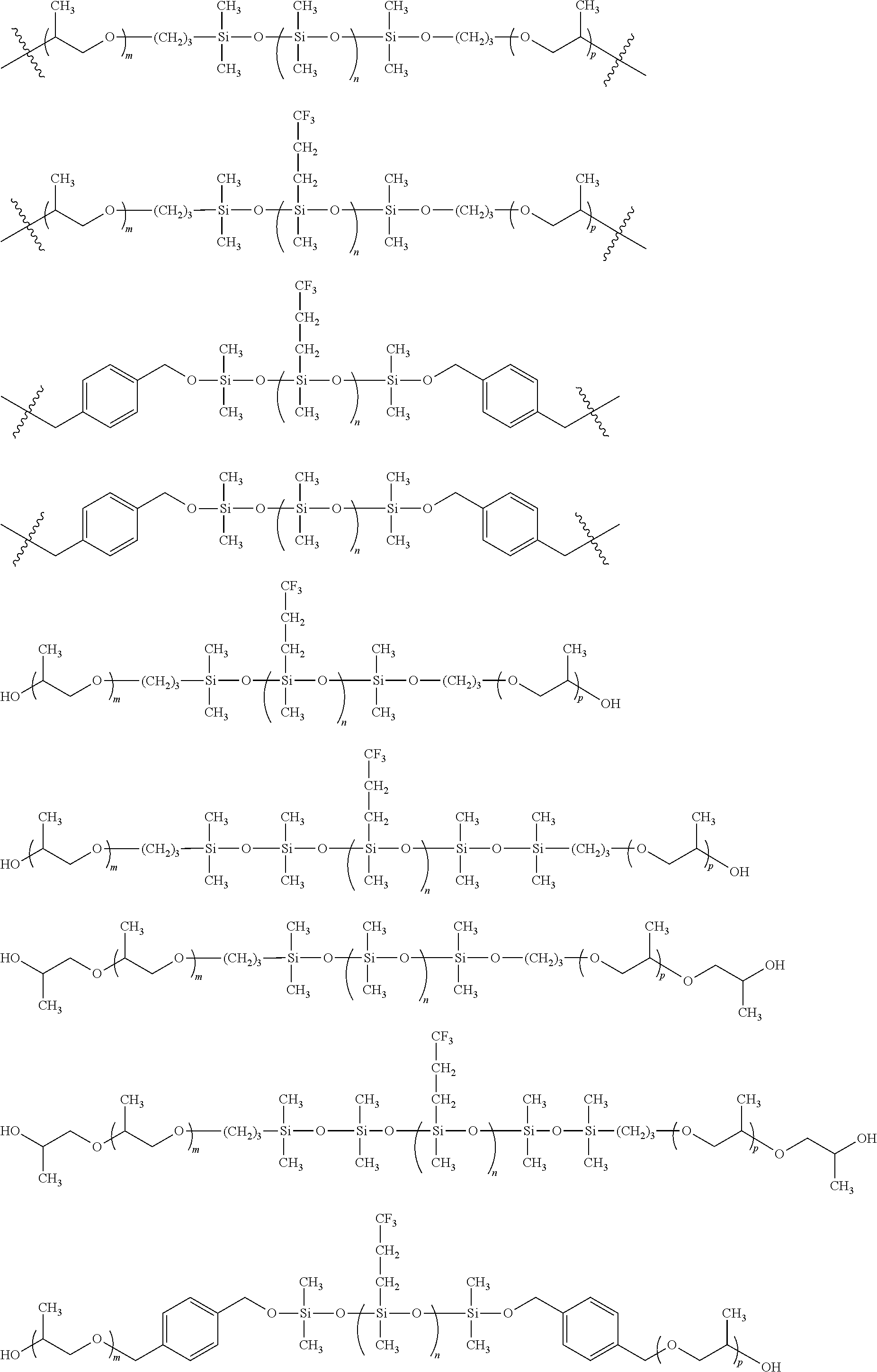
- wherein each of m, n, and p is as defined and described herein.
- In some embodiments, the present invention provides a polymer foam, comprising:
-
- (a) one or more triblock copolymers of formula I:
-

-
- wherein each of X, Y, m, n, p, L1, L2, R1, R2, R3, R4, R5, and R6 is as defined and described herein; and
- (b) wherein the copolymers are chemically interspersed (bound) between urethane and/or urea linkages (i.e., at the bond designated with ).
- The invention further provides a pre-formed soft segment of the formula I as defined above. In some embodiments, the present invention provides a polyurethane/urea foam comprising a soft segment triblock copolymer of formula I.
- In some embodiments, the present invention provides a viscoelastic biostable water blown foam, comprising:
-
- (a) one or more triblock copolymers of formula I:
-

-
- wherein each of X, Y, m, n, p, L1, L2, R1, R2, R3, R4, R5, and R6 is as defined and described herein; and
- (b) wherein the copolymers are chemically interspersed (bound) between urethane and/or urea linkages (i.e., at the bond designated with ).
- It has been surprisingly found that polyurethanes and/or polyureas comprising a triblock copolymer of the present invention are stable to gastric fluid. Such polyurethanes and polyureas prepared using triblock copolymers of the present invention are viscoelastic and stable to gastric fluid. In some embodiments, a provided viscoelastic material is a foam.
- In certain embodiments, a provided biostable foam is stable to gastric fluid. In some embodiments, a provided biostable foam is stable to gastric fluid for at least one year. In some embodiments, a provided biostable foam is stable to gastric fluid for at least 3 months, for at least 4 months, for at least 5 months, for at least 6 months, for at least 7 months, for at least 8 months, for at least 9 months, for at least 10 months, for at least 11 months, or for at least one year. Methods for determining stability of a provided biostable foam are known in the art utilizing simulated gastric fluid and include those described in detail in the Exemplification, infra.
- In some embodiments, a provided viscoelastic foam, comprising a triblock copolymer of the present invention, is characterized in that the foam takes up less than about 30% by weight of water at equilibrium. In certain embodiments, a provided viscoelastic foam takes up less than about 5%, less than about 10%, less than about 15%, less than about 20%, less than about 25%, or less than about 30% by weight of water at equilibrium. One of ordinary skill in the art will appreciate that such chemical stability (i.e., in gastric fluid and therefore at very low pH) and hyrophobicity (i.e., water uptake of less than about 30% by weight) are characterisitics that differ dramatically from known siloxane polymers that are utilized in, e.g., the manufacture of contact lenses. For example, siloxane polymer that are utilized in, e.g., the manufacture of contact lenses require a water uptake of 50-120%.
- As described above, the present invention provides a viscoelastic foam comprising a triblock copolymer of the present invention. It was surprisingly found that a provided foam has a high elongation capacity and the ability to recover very slowly following elongation. Indeed, it was found that a provided viscoelastic foam has an elongation capacity of about 200-1200%. In some embodiments, a provided viscoelastic foam has an elongation capacity of about 500%.
- In some embodiments, a provided viscoelastic foam has a tensile strength of about 0.1 to about 1.0 MPa. In certain embodiments, a provided viscoelastic foam has a tensile strength of about 0.25 to about 0.5 MPa.
- In some embodiments, a provided viscoelastic foam has a Young's Modulus of about 0.1 to about 0.6 MPa. In certain embodiments, a provided viscoelastic foam has a Young's Modulus of about 0.1 to about 0.5 MPa.
- One of ordinary skill in the art will appreciate that, depending upon the physical characteristics required for a particular use of a provided foam, a foam of varying densities can be prepared. For example, a valve having a thinner wall would require a foam having a higher density than a similar valve having a thicker wall in order to result in each valve having a similar physical characteristic (e.g., tensile strength, and the like). Thus, in certain embodiments, a provided viscoelastic foam has a density of 0.1 to 1.5 g/cm3. In certain embodiments, a provided viscoelastic foam has a density of 0.3 to 1.2 g/cm3. In certain embodiments, a provided viscoelastic foam has a density of 0.8 to 0.9 g/cm3. In some embodiments, a provided viscoelastic foam has a density of 0.5 to 0.6 g/cm3.
- In certain embodiments, the present invention provides polyether-siloxane and polyether-fluorosiloxane polyurethane materials with a greatly reduced number of weak-links as illustrated by
FIG. 86 andFIG. 87 . This was achieved by preforming the soft segment prior to the polyurethane reaction. In the examples below a triblock copolymer based on polydimethyl siloxane and polypropylene oxide was used but it will be appreciated that other triblock copolymers such as those formed from polysiloxanes and poly(ethylene oxide), poly(difluoromethyl ethylene oxide), poly(trifluoromethyl ethylene oxide), poly(propylene oxide), poly(difluoromethyl propylene oxide), poly(propylene oxide), poly(trifluoromethyl propylene oxide), poly(butylene oxide), poly(tetramethylene ether glycol), poly(tetrahydrofuran), poly(oxymethylene), poly(ether ketone), poly(etherether ketone) and copolymers thereof, poly(dimethylsiloxane), poly(diethylsiloxane) and higher alkyl siloxanes, poly(methyl phenyl siloxane), poly(diphenyl siloxane), poly(methyl di-fluoroethyl siloxane), poly(methyl tri-fluoroethyl siloxane), poly(phenyl di-fluoroethyl siloxane), poly(phenyl tri-fluoroethyl siloxane) and copolymers thereof, poly(ethylene terephthalate) (PET), poly(ethylene terephthalate ionomer) (PETI), poly(ethylene naphthalate) (PEN), poly(methylene naphthalate) (PTN), poly(butylene teraphalate) (PBT), poly(butylene naphthalate) (PBN) and polycarbonate could be used. - Referring to
FIG. 86 , copolymers of the form ABA, ABC and BAB were produced from homopolymers of polysiloxane and polypropylene oxide which were covalently linked using bonds less labile than urethane/urea. The molecular weight and chemical characteristics of such homopolymers were tailored to achieve a pre-soft-segment with the appropriate balance of hydrophilicity/hydrophobicity. Without wishing to be bound by any particular theory, it is believe that by using a non-urethane linked tri-block copolymer instead of the constituent homopolymers as soft segments that the mechanical characteristics and hydrolytic stability of the resulting material is substantially improved. - In some embodiments, the present invention provides a foam comprising a copolymer of the present invention. Such foams offer specific advantages over solid elastomers, especially for gastrointestinal device applications. These advantages include enhanced biostability in the gastric environment, compressibility, viscoelasticity and high ‘surface area to volume ratio’. The foam formulations of the invention can mimic mechanical characteristics of the native gastrointestinal tissue.
- A biostable water blown foam was prepared from heterogenous reagents.
- The prior art describes polyurethane foams that are prepared by the sequential reaction of polymer chains to one another resulting in a high molecular weight solid material. In all cases the polymeric precursors described in the art are linked together by urethane/urea linkages as illustrated in
FIG. 85 . However, each urethane/urea linkage is a possible site for degradation. - In the invention we have prepared a biostable polyurethane/urea foam with much fewer ‘weak links’ by using co-polymer precursors as shown in
FIG. 86 . - Polyurethane reactions have historically been carried out in a single phase due to ease of processing. However, we have made novel materials by combining physically heterogenous reaction pre-cursors together to form a stable two-phase dispersion ('water-in-oil') which was then reacted to form a foam.
- In two specific examples X and Y are both polyethers namely poly(propylene oxide) (PPO). These were formulated into copolymers with poly(dimethylsiloxane) (PDMS) and poly(trifluoropropyl methylsiloxane) respectively in varying ratios as described by the following formulae:
-

- The formulations contained a number of other components including:
-

- Diethanolamine (DEOA) is used as a branching agent although it is sometimes known as a crosslinking agent. The molecular weight of DEOA is 105.14 g/mol. The effect of the DEOA is to influence softness and elasticity of the end polymer.
-

- Bismuth neodecanoate is supplied as BiCat 8108M from Shepherd. It has a molecular weight of 722.75 g/mol. This catalyst is used to facilitate the complete reaction between isocyanate and hydroyl or amine functional groups.
-

- DABCO is a common blowing catalyst for reaction between NCO and H2O. It has a molecular weight of 112.17 g/mol. This catalyst has the effect, in combination with H2O, of manipulating the foam rise characteristics.
- This is a 2 step process. In the first step silanol terminated poly(trifluoropropyl methyl siloxane) is converted into its dihydride derivative. In the next step, this dihydride derivative is reacted with the allyl terminated poly(propylene glycol).
- The synthetic procedure is as follows:
-

- To a 4 neck separable flask fitted with mechanical stirrer, was added 40 g of Silanol terminated poly(trifluoropropyl methylsiloxane) (FMS-9922 from Gelest Inc.) and this was mixed with 50 ml of toluene and fitted with a continuous flush of Nitrogen. To the reaction mixture 7.57 g of dimethyl chlorosilane (DMCS, from Sigma Aldrich) was added slowly over about 20 minutes keeping the temperature of the mixture constant at 30° C. With each addition of dimethyl chlorosilane, the mixture became hazy but cleared in a short period of time. Once the addition of dimethyl chlorosilane was complete, the mixture was heated to 90° C. for 3 hours. The reaction was then washed with excess water several times to reduce the acidity of the mixture. The resulting mixture was dried over silica gel, filtered and vacuumed to remove solvent and traces of water at 65° C. overnight. A clear fluid was then obtained with a very strong Si—H band in infra red spectroscopy (IR) at 2130 cm−1, which confirms the reaction. GPC analysis showed the molecular weight to be 1200 g/mol.
-

- To 90 ml of reagent grade toluene in a 4 neck separable flask fitted with mechanical stirrer, 46.67 g of Allyl terminated poly(propylene glycol) (MW=700 g/mol, Jiangsu GPRO Group Co.) was added and then heated to reflux. Then 40 g of Hydride terminated FMS-9922 was dissolved in 50 ml of reagent grade toluene and the temperature raised to around 90° C. To the
reaction mixture 2 drops of hexachloroplatinic(IV) acid (0.01M H2PtCl6 from Sigma) solution in isopropanol (by Merck) was then added. After this catalyst solution had been added, the mixture was refluxed for 1 hour and the solvent distilled off in order to get the final product. The reaction was followed by H-NMR and gel permeation chromatography (GPC) confirmed the final molecular weight to be 2700 g/mol. -
TABLE 1 Resulting polymer block ratios Stoiciometric ratios for reaction product: Polymer block PO F—SiO PO m n p Ratio 11 9.7 11 - To 130 ml of reagent grade toluene in a separable flask fitted with a mechanical stirrer, was added 64 g of allyl terminated poly(propylene glycol) (MW=700 g/mol, Jiangsu GPRO Co.) and both were mixed and heated to reflux. Then 40 g of hydride terminated poly(dimethyl siloxane) (
Silmer H Di 10 by Siltech Corp.) was dissolved in 50 ml reagent grade toluene and the temperature raised to around 90° C. To thisreaction mixture 2 drops of hexachloroplatinic(IV) acid (0.01M H2PtCl6 from Sigma) solution in isopropanol was added. After this catalyst solution was added, the mixture was refluxed for 1 hour and then the solvent was distilled off in order to get the final product. The reaction was followed with H-NMR and gel permeation chromatography (GPC) confirmed the final molecular weight of the product to be 2300 g/mol. -

-
TABLE 2 Polymer block ratios Stoiciometric ratios for reaction product: Polymer block PO SiO PO m n p Ratio 11 11 11 -

- To a 100 ml separable flask fitted with a mechanical stirrer, 15 g of hydroxy terminated polydimethyl siloxane (DMS-S14 from Gelest Inc.) was added along with 5.36 g of di-chloro p-xylene (from Sigma) and 0.0089 g of Copper(II) acetylacetonate (Cu(Acac)2 from Sigma). The reaction mixture was refluxed at 110° C. for 5 hrs. At this point, 19.77 g of hydroxy terminated poly(propylene glycol) (from Sigma) was added dropwise and the reaction mixture was then refluxed for another 15 hr. The progress of reaction was followed by 1H-NMR and the final molecular weight, determined by gel permeation chromatography (GPC), was 3000 g/mol.
- H-NMR analysis: Solvent used for 1H-NMR analysis is CDCl3. Aromatic H=7.25-7.45 ppm, —CH2=4.5-4.6 ppm, —CH3 (of PPO)=1-1.4 ppm, —CH2 (of PPO)=3.2-3.8 ppm, —OH (of PPO)=3.8-4 ppm, —CH3(silanol)=0.5-0.8 ppm.
-
TABLE 3 Resulting polymer block ratios Stoiciometric ratios for reaction product: Polymer block PO SiO PO m n p Ratio 14 15.5 14 -

- To a 100 ml separable flask fitted with a mechanical stirrer, 15 g of hydroxy terminated polytrifluoromethyl siloxane (FMS-9922, Gelest inc.) was added along with 5.9 g of di-chloro p-xylene and 0.0098 g of copper(II) acetylacetonate (Cu(Acac)2 from Sigma). The reaction mixture was refluxed at 110° C. for 5 hrs. At this point, 21.75 g of hydroxy terminated poly(propylene glycol) (from Sigma) was added dropwise to the reaction mixture. The reaction was refluxed for another 15 hr. The progress of reaction was followed by 1H-NMR analysis and the molecular weight, determined by gel permeation chromatography (GPC), was 3100 g/mol.
- 1H-NMR analysis: Solvent used for H-NMR analysis is CDCl3.
- Aromatic 1H=7.25-7.45 ppm, —CH2=4.5-4.6 ppm, —CH3 (of PPO)=1-1.4 ppm, —CH2 (of PPO)=3.2-3.8 ppm, —OH (of PPO)=3.8-4 ppm, —CH3(silanol)=0.5-0.8 ppm.
-
TABLE 4 Polymer block ratios Stoiciometric ratios for reaction product: Polymer block PO FSiO PO m n p Ratio 14 9.2 14 - The pre-soft segments prepared can be described as having polymer block ratios which are numerically represented by the letters m, n and o for the constituents PO/SiO/PO respectively. The triblock copolymers prepared in Examples 1 and 2 with specific m, n, o ratios were formulated into polyurethane/urea foams as illustrated by Table 7.
- The process for preparing the foam was a two-step procedure. The following describes the method of manufacture of the first product in Table 7. The same procedure was used to prepare other foams as described by Table 8.
- Step 1) Firstly a mixture was made with 0.041 g of DABCO LV-33 (Airproducts), 0.120 g of bismuth neodecanoate (Bicat 8108M from Shepherd chemicals), 0.467 g of diethanol amine (DEOA, from Sigma), 7.917 g of synthesized block copolymer, 0.200 g water and 0.1 g of surfactant (Niax L-618 from Airproducts) in a plastic flat bottomed container. This is then thoroughly mixed manually for 30 sec until a homogenous mixture was obtained.
- Step 2) To the above mixture, 15 g of a diisocyanate prepolymer (PPT 95A Airproducts) was added. This was then thoroughly mixed by a mechanical stirrer for about 5 seconds. The material was then molded and cured at 70° C. for 2.5 hours and post cured at 50° C. for another 3 hours.
-
TABLE 5 Formulation details for foam Polymer block Formulation (PO/SiO/PO) Identification Ratio m:n:p DABCO BICAT DEOA H2O VF230209A 11:11:11 0.0325 0.015 0.40 1.0 VF090309B 11:9:11 0.0325 0.015 0.40 1.0 - Comparative Example of Formulation of Water Blown Foam from Triblock Copolymer Pre-Soft Segment and Individual Homopolymers
- Polyurethane/urea polymer foams from Example 5 were compared to foams made from the stoichiometric equivalent homopolymer soft segments. The foams with homopolymer based soft segments (VF130309 and VF190309) shown in
FIG. 88 were produced as follows (VF130309): - Step 1) Firstly a mixture was made with 0.041 g of DABCO LV-33 (Airproducts), 0.120 g of bismuth neodecanoate (Bicat 8108M from Shepherd chemicals), 0.467 g of diethanol amine (DEOA, from Sigma), 3.056 g of poly(dimethyl siloxane) diol (DMS-s14 Gelest Inc.), 1.633 g of polypropylene oxide (Mw=700 g/mol), 0.200 g water and 0.1 g of surfactant (Niax L-618 from Airproducts). These were added to a plastic flat bottomed container and were thoroughly mixed manually for 30 sec until a homogenous mixture was obtained.
- Step 2) To the above mixture, 15 g of a diisocyanate prepolymer (PPT 95A Airproducts) was added. This was then thoroughly mixed by a mechanical stirrer for 5 seconds. The material was then molded and cured at 70° C. for 2.5 hours and post cured at 50° C. for another 3 hours.
- The foams in this example were made into dumbell shapes for tensile testing.
FIGS. 88 and 89 illustrate the difference in mechanical behaviour between the comparative materials indicating a favourable lowering in modulus for the triblock copolymer pre-soft-segments. - Tensile test specimens were prepared in the same manner to the materials used in Example 4 and were subjected to accelerated aging in simulated gastric fluid (as per United States Pharmacopeia, “USP”). The materials produced with the pre-synthesised triblock copolymer soft segments resulted in substantially improved mechanical stability in gastric fluid as compared to the urethane/urea linked homopolymer equivalent as illustrated in
FIG. 90 . This facilitates the use of such materials for prolonged periods in digestive and more specifically gastric environments. - Several water blown polyurethane/urea foams were also produced with varying PO/EO/SiO polymer block ratios. The process for preparing the foam as described above was used.
-
TABLE 6 Water blown formulations incorporating siloxane containing copolymer pre-soft-segments. Polymer block ratio (PO/EO/SiO) m:n:p DABCO BICAT DEOA H2O 41.5:8.3:0.5 0.114 0.022 0.22 2.72 40.2:7.8:0.5 0.114 0.022 0.22 2.72 37.5:7:0.5 0.114 0.022 0.22 2.72 33.5:5.7:0.5 0.114 0.022 0.22 2.72 29.6:4.4:0.5 0.114 0.022 0.22 2.72 21.6:1.8:0.5 0.114 0.022 0.22 2.72 19:1:0.5 0.114 0.022 0.22 2.72 29.6:4.5:1.1 0.114 0.022 0.22 2.72 - The results from the formulations described in Table 6 are shown in Table 7.
-
TABLE 7 Results from mechanical testing of foams from Table 5 Polymer block ratio (PO/EO/SiO) m:n:p % Elongation Tensile Strength (N) 41.5:8.3:0.5 233 0.46 40.2:7.8:0.5 243 0.31 37.5:7:0.5 237 0.3 33.5:5.7:0.5 260 0.23 29.6:4.4:0.5 320 0.23 21.6:1.8:0.5 497 0.23 19:1:0.5 462 0.22 29.6:4.5:1.1 437 0.29 - Devices for use in the gastrointestinal system have historically not been made from specifically designed materials. Off the shelf materials used for application in the corrosive environment of the stomach have limited biostability and generally lose their functionality after a short time.
- The foam of the invention can be used for production of a valve of the type described in our US2007-0198048A, the entire contents of which are incorporated herein by reference. The valve has an open position and a closed position. The valve will have a proximal end and a distal end. The valve material can open from the proximal direction when the action of swallowing (liquid or solid) stretches an orifice by between 100% and 3000% in circumference. The open orifice optionally closes non-elastically over a prolonged period of time, thus mimicking the body's natural response. The duration taken to close may be between 2 and 15 sec. The material can stretch to between 100%-300% from the distal direction when gas, liquid or solids exceeds a pre-determined force of between 25 cmH2O and 60 cmH2O. In some embodiments, the material absorbs less than 15% of its own mass of water at equilibrium. In some embodiments, the material loses (leaches) less than 3% of it's own mass at equilibrium in water or alcohol. In some embodiments, the material loses less than 10% of its tensile strength when immersed in a simulated gastric fluid at pH 1.2 for 30 days. In some embodiments, the valve material loses less than 25% of its % elongation when immersed in a simulated gastric fluid at pH 1.2 for 30 days.
- The healthy lower esophageal sphincter (LES) remains closed until an individual induces relaxation of the muscle by swallowing and thus allowing food to pass in the antegrade direction. Additionally when an individual belches or vomits they generate enough pressure in the stomach in the retrograde direction to overcome the valve. An anti-reflux valve must enable this functionality when placed in the body, thus a simple functional test is carried out to asses performance.
- It has been reported that post fundoplication patients have yield pressures between 22-45 mmHg and that most of the patients with gastric yield pressure above 40 mmHg experienced problems belching. See Yield pressure, anatomy of the cardia and gastro-oesophageal reflux. Ismail, J. Bancewicz, J. Barow British Journal of Surgery. Vol: 82, 1995, pages: 943-947. Thus, in order to facilitate belching but prevent reflux, an absolute upper GYP value of 40 mmHg (550 mmH2O) is reasonable. It was also reported that patients with visible esophagitis all have gastric yield pressure values under 15 mmHg, therefore, there is good reason to selectively target a minimum gastric yield pressure value that exceeds 15 mmHg See Id. An appropriate minimum gastric yield pressure value would be 15 mmHg+25% margin of error thus resulting in a minimum effective valve yield pressure value of 18.75 mmHg or 255 mmH2O.
- The test apparatus consists of a 1 m high vertical tube as shown in
FIG. 91 , to which is connected a peristaltic pump and a fitting that is designed to house the valve to be tested. - The valve to be tested is placed in a water bath at 37° C. for 30 minutes to allow its temperature to equilibrate. Once the temperature of the valve has equilibrated it is then installed into the housing such that the distal closed end of the valve faces the inside of the test apparatus. The pump is then switched on at a rate of 800 ml/min to begin filling the vertical tube. The rising column of water exerts a pressure that forces the valve shut initially. As the pressure in the column rises the valve reaches a point where it everts and allows the water to flow through. This point, known as the yield pressure, is then recorded and the test repeated four times.
- Clinical Condition being Simulated
- The lower oesophagus of a normal patient can be exposed to the acidic contents of the stomach periodically without any adverse side effects. However, patients with gastro esophageal reflux disease experience damage to the mucosa of the lower oesophagus due to increased exposure to the gastric contents. Exposure of the lower oesophagus to acidic gastric contents is routinely measured in the clinic using dedicated pH measurement equipment. A typical procedure involves measuring pH over a 24-hour period. The levels of acid exposure in pathological reflux disease patients is summarised in Table 8 from six clinical references. See DeMeester T R, Johnson L F, Joseph G J, et al. Patterns of Gastroesophageal Reflux in Health and Disease Ann. Surg. October 1976 459-469; Pandolfino J E, Richter J E, Ours T, et al. Ambulatory Esophageal pH Monitoring Using a Wireless System Am. J. Gastro 2003; 98:4; Mahmood Z, McMahon B P, Arfin Q, et al. Results of endoscopic gastroplasty for gastroesophageal reflux disease: a one year prospective follow-up Gut 2003; 52:34-9; Park P O, Kjellin T, Appeyard M N, et al. Results of endoscopic gastroplasty suturing for treatment of GERD: a multicentre trial Gastrointest endosc 2001; 53:AB115; Filipi C J, Lehman G A, Rothstein R I, et al. Transoral flexible endoscopic suturing for treatment of GERD: a multicenter trial Gastrointest endosc 2001; 53 416-22; and Arts J, Slootmaekers S Sifrim D, et al. Endoluminal gastroplication (Endocinch) in GERD patient's refractory to PPI therapy Gastroenterology 2002; 122:A47.
-
TABLE 8 Summary of acid exposure in patients with reflux disease Investigator Number of patients Details % 24 h < pH 4DeMeester 54 Combined refluxers 13.5 Pandolfino 41 Gerd 6.5 Mahmood 21 Gerd 11.11 Park 142 Gerd 8.5 Filipi 64 Gerd 9.6 Arts 20 Gerd 17 Average 11.035 - Considering that the lower oesophagus is exposed to the acidic pH exposure time for an average of 11% of the measurement period, an accelerated aging methodology can easily be conceived. Constant exposure of a test material to the gastric contents (or USP Simulated Gastric Fluid—Reference USP Pharmacopeia) would represent an almost 10-fold increase in the rate of aging. Thus the time required to simulate one year of exposure of the lower oesophagus to the gastric contents is described by
equation 1. -
- Immersion of test specimens in USP Simulated gastric fluid for 40.27 days at 37° C. will approximate one year's exposure of the lower oesophagus to acidic gastric contents in a GERD patient's scenario.
-
Simulated Exposure Real Time 1 year 40.28 days 2 years 80.56 days 3 years 120.84 days - Results of accelerated stability of a valve prepared from a viscoelastic foam of the present invention are depicted in
FIGS. 92A and 92B . - While we have described a number of embodiments of this invention, it is apparent that our basic examples may be altered to provide other embodiments that utilize the compounds and methods of this invention. Therefore, it will be appreciated that the scope of this invention is to be defined by the appended claims rather than by the specific embodiments that have been represented by way of example.
- Various features of the invention are described in detail and illustrated herein. Appropriate features described with reference to one embodiment may be utilised in addition to and/or as a substitute for features described in other embodiments.
- The invention is not limited to the embodiments hereinbefore described which may be varied in detail.
Claims (33)
1. A valve having:—
a normally closed configuration in which the valve is closed;
an open configuration in which the valve is opened for flow through the valve; and
a support for the valve, the support being adapted for mounting to a pre-deployed luminal prosthesis intermediate a proximal end and a distal end of the predeployed luminal prosthesis.
2. A valve as claimed in claim 1 wherein the luminal prosthesis comprises a stent.
3. A valve as claimed in claim 1 wherein the luminal prosthesis comprises an esophageal stent.
4. A valve as claimed in claim 1 wherein the valve support comprises a support structure.
5. A valve as claimed in claim 4 wherein the support structure tapers outwardly.
6. A valve as claimed in claim 4 wherein the support structure tapers inwardly.
7. A valve as claimed in claim 4 wherein the support structure is of generally uniform diameter along the length hereof.
8. A valve as claimed in claim 4 wherein the support structure comprises a scaffold.
9. A valve as claimed in claim 4 wherein the support structure comprises a stent-like structure.
10. A valve as claimed in claim 4 comprising mounting means for mounting the valve support to a pre-deployed luminal prosthesis.
11. A valve as claimed in claim 10 wherein the mounting means is provided by the support structure.
12. A valve as claimed in claim 11 wherein the mounting means comprises protrusions extending from the support structure.
13. A valve as claimed in claim 12 wherein the protrusions extend from the support structure adjacent to a proximal end of the support structure.
14. A valve as claimed in claim 12 wherein the protrusions extend from the support structure adjacent to a distal end of the support structure.
15. A valve as claimed in claim 12 wherein the protrusions extend from the support structure intermediate a proximal end and a distal end of the support structure.
16. A valve as claimed in claim 12 wherein the protrusions are adapted to engage with a pre-deployed host support.
17. A valve as claimed in claim 12 wherein the protrusion comprises a loop.
18. A valve as claimed in claim 12 wherein the apicial tip of the protrusion is rounded.
19. A valve as claimed in claim 12 wherein the protrusions are releasable engagable with a pre-deployed host support.
20. A valve as claimed in claim 12 comprising release means for releasing the valve from engagement with a pre-deployed host support.
21. A valve as claimed in claim 20 wherein the release means comprises means for reducing the diameter of at least portion of the valve support structure.
22. A valve as claimed in claim 20 wherein the release means comprises a drawstring extending around the valve support structure.
23. A valve as claimed in claim 22 wherein a first drawstring extends around a proximal end of the support structure.
24. A valve as claimed in claim 22 wherein a second drawstring extends around a distal end of the support structure.
25. A valve as claimed in claim 4 wherein the valve is mounted to the support structure.
26. A valve as claimed in claim 1 wherein the valve is an esophageal valve for mounting to an esophageal stent.
27. A valve device comprising a valve as claimed in claim 1 and a luminal prosthesis.
28. A method for providing a valve in a body passageway comprising the steps of:—
providing a valve mounted to a support structure;
delivering the valve mounted to the support structure to a pre-deployed luminal prosthesis in the body passageway; and
deploying the valve so that the valve is mounted to the luminal prosthesis.
29. A method as claimed in claim 28 wherein the step of deploying the valve comprises engaging the valve support with the pre-deployed luminal prosthesis.
30. A method as claimed in claim 29 comprising the step of releasing the valve support from engagement with the luminal prosthesis.
31. A method as claimed in claim 30 comprising repositioning the valve support within the prosthesis.
32. A method as claimed in claim 30 comprising removing the valve from the prosthesis.
33. A method as claimed in claim 28 wherein the body passageway is the esophagus and the valve is an esophageal valve for mounting to a pre-deployed esophageal stent.
Priority Applications (2)
| Application Number | Priority Date | Filing Date | Title |
|---|---|---|---|
| US12/971,464 US20110160836A1 (en) | 2008-06-20 | 2010-12-17 | Valve device |
| US13/745,678 US20130345786A1 (en) | 2008-06-20 | 2013-01-18 | Valve device |
Applications Claiming Priority (11)
| Application Number | Priority Date | Filing Date | Title |
|---|---|---|---|
| US7440008P | 2008-06-20 | 2008-06-20 | |
| US7439308P | 2008-06-20 | 2008-06-20 | |
| US14533709P | 2009-01-16 | 2009-01-16 | |
| US14533209P | 2009-01-16 | 2009-01-16 | |
| US15196809P | 2009-02-12 | 2009-02-12 | |
| US15197309P | 2009-02-12 | 2009-02-12 | |
| US17453609P | 2009-05-01 | 2009-05-01 | |
| US18104309P | 2009-05-26 | 2009-05-26 | |
| US12/487,991 US20100121461A1 (en) | 2008-06-20 | 2009-06-19 | Valve |
| US28797309P | 2009-12-18 | 2009-12-18 | |
| US12/971,464 US20110160836A1 (en) | 2008-06-20 | 2010-12-17 | Valve device |
Related Parent Applications (1)
| Application Number | Title | Priority Date | Filing Date |
|---|---|---|---|
| US12/487,991 Continuation-In-Part US20100121461A1 (en) | 2008-06-20 | 2009-06-19 | Valve |
Related Child Applications (1)
| Application Number | Title | Priority Date | Filing Date |
|---|---|---|---|
| US13/745,678 Continuation US20130345786A1 (en) | 2008-06-20 | 2013-01-18 | Valve device |
Publications (1)
| Publication Number | Publication Date |
|---|---|
| US20110160836A1 true US20110160836A1 (en) | 2011-06-30 |
Family
ID=44188458
Family Applications (2)
| Application Number | Title | Priority Date | Filing Date |
|---|---|---|---|
| US12/971,464 Abandoned US20110160836A1 (en) | 2008-06-20 | 2010-12-17 | Valve device |
| US13/745,678 Abandoned US20130345786A1 (en) | 2008-06-20 | 2013-01-18 | Valve device |
Family Applications After (1)
| Application Number | Title | Priority Date | Filing Date |
|---|---|---|---|
| US13/745,678 Abandoned US20130345786A1 (en) | 2008-06-20 | 2013-01-18 | Valve device |
Country Status (1)
| Country | Link |
|---|---|
| US (2) | US20110160836A1 (en) |
Cited By (72)
| Publication number | Priority date | Publication date | Assignee | Title |
|---|---|---|---|---|
| US20100121462A1 (en) * | 2008-06-20 | 2010-05-13 | Vysera Biomedical Limited | Valve |
| US20100256776A1 (en) * | 2005-01-19 | 2010-10-07 | Gi Dynamics, Inc. | Eversion Resistant Sleeves |
| WO2013019851A1 (en) * | 2011-08-04 | 2013-02-07 | Cook Medical Technologies Llc | Non-woven helical wire stent |
| US20130073025A1 (en) * | 2011-09-16 | 2013-03-21 | Ghassan S. Kassab | Devices and methods for assisting valve function, replacing venous valves, and predicting valve treatment success |
| WO2013163076A1 (en) * | 2012-04-27 | 2013-10-31 | Cook Medical Technologies Llc | Anti-aspiration valve |
| WO2014015212A1 (en) * | 2012-07-20 | 2014-01-23 | Cook Medical Technologies Llc | Implantable medical device having a sleeve |
| US20140031923A1 (en) * | 2012-07-25 | 2014-01-30 | Medtronic Vascular Galway Limited | Trans-Aortic Surgical Syringe-Type Device for Deployment of a Prosthetic Valve |
| WO2014026870A2 (en) * | 2012-08-15 | 2014-02-20 | Pfm Medical Ag | Implantable device for use in the human and/or animal body to replace an organ valve |
| US20140074219A1 (en) * | 2012-09-12 | 2014-03-13 | Boston Scientific Scimed, Inc. | Adhesive stent coating for anti-migration |
| US20140135908A1 (en) * | 2012-11-14 | 2014-05-15 | Medtronic, Inc. | Transcatheter Valve Prosthesis Having a Variable Shaped Cross-Section for Preventing Paravalvular Leakage |
| US20140257461A1 (en) * | 2013-03-05 | 2014-09-11 | Merit Medical Systems, Inc. | Reinforced valve |
| CN104382671A (en) * | 2014-09-11 | 2015-03-04 | 南京微创医学科技有限公司 | Degradable human body stent capable of effectively preventing transposition and reducing hyperplasia and manufacturing method |
| US20150290006A1 (en) * | 2012-12-07 | 2015-10-15 | Karl Stangl | Method of preventing or alleviating high venous pressure due to tricuspid regurgitation in a patient |
| EP2957267A1 (en) * | 2014-06-20 | 2015-12-23 | Ethicon Endo-Surgery, Inc. | Artificial sphincter |
| WO2015195252A1 (en) * | 2014-06-20 | 2015-12-23 | Ethicon Endo-Surgery, Inc. | Artificial esophageal sphincter |
| US20150374484A1 (en) * | 2014-06-26 | 2015-12-31 | Boston Scientific Scimed, Inc. | Medical devices and methods to prevent bile reflux after bariatric procedures |
| US9314325B2 (en) | 2012-04-27 | 2016-04-19 | Cook Medical Technologies Llc | Anti-aspiration prosthesis |
| US9358095B2 (en) | 2012-10-24 | 2016-06-07 | Cook Medical Technologies Llc | Anti-reflux prosthesis |
| EP2967927A4 (en) * | 2013-03-15 | 2016-10-12 | Merit Medical Systems Inc | Esophageal stent |
| US9498314B2 (en) | 2009-12-18 | 2016-11-22 | Coloplast A/S | Urological device |
| US9526605B2 (en) | 2013-01-08 | 2016-12-27 | Cook Medical Technologies Llc | Multi valve anti-reflux prosthesis |
| US9713522B2 (en) | 2011-10-31 | 2017-07-25 | Merit Medical Systems, Inc. | Esophageal stent with valve |
| US20170216027A1 (en) * | 2014-01-20 | 2017-08-03 | Tricares SAS | Heart valve anchoring device |
| WO2017155885A1 (en) * | 2016-03-07 | 2017-09-14 | Boston Scientific Scimed, Inc. | Esophageal stent including a valve member |
| WO2017199098A1 (en) * | 2016-05-20 | 2017-11-23 | Siersema Peter Derk | Device and method for treatment of barrett's esophagus |
| CN107530160A (en) * | 2015-02-20 | 2018-01-02 | 波士顿科学国际有限公司 | Support with the anchor log that can bounce back |
| EP3278768B1 (en) | 2012-12-19 | 2019-03-13 | W.L. Gore & Associates, Inc. | Improved prosthetic heart valve with leaflet shelving |
| CN110301994A (en) * | 2019-08-07 | 2019-10-08 | 南京鼓楼医院 | A kind of artificial ileocaecal sphineter device |
| EP2765959B1 (en) * | 2011-10-11 | 2019-10-09 | Cook Medical Technologies LLC | Stent delivery, repositioning, and removal system |
| US10583000B2 (en) * | 2013-03-14 | 2020-03-10 | Edwards Lifesciences Cardiaq Llc | Prosthesis for atraumatically grasping intralumenal tissue and methods of delivery |
| US20200121458A1 (en) * | 2018-10-22 | 2020-04-23 | Vdyne, Llc | Guidewire Delivery of Transcatheter Heart Valve |
| US10639144B2 (en) | 2012-12-19 | 2020-05-05 | W. L. Gore & Associates, Inc. | Vertical coaptation zone in a planar portion of prosthetic heart valve leaflet |
| US10716664B2 (en) | 2013-03-14 | 2020-07-21 | Edwards Lifesciences Cardiaq Llc | Prosthesis for atraumatically grasping intralumenal tissue and methods of delivery |
| US10881507B2 (en) | 2012-12-19 | 2021-01-05 | W. L. Gore & Associates, Inc. | Prosthetic valves, frames and leaflets and methods thereof |
| US10959842B2 (en) | 2017-09-12 | 2021-03-30 | W. L. Gore & Associates, Inc. | Leaflet frame attachment for prosthetic valves |
| US10966820B2 (en) | 2012-12-19 | 2021-04-06 | W. L. Gore & Associates, Inc. | Geometric control of bending character in prosthetic heart valve leaflets |
| US10987218B2 (en) | 2017-10-31 | 2021-04-27 | W. L. Gore & Associates, Inc. | Transcatheter deployment systems and associated methods |
| US11020221B2 (en) | 2017-09-27 | 2021-06-01 | W. L. Gore & Associates, Inc. | Prosthetic valve with expandable frame and associated systems and methods |
| US11039917B2 (en) | 2012-12-19 | 2021-06-22 | W. L. Gore & Associates, Inc. | Geometric prosthetic heart valves |
| CN113017914A (en) * | 2021-03-17 | 2021-06-25 | 复旦大学附属中山医院 | Peripheral blood vessel composite stent for preventing intimal hyperplasia at access opening of covered stent |
| US11065112B2 (en) | 2014-08-18 | 2021-07-20 | W. L. Gore & Associates, Inc. | Frame with integral sewing cuff for prosthetic valves |
| USD926322S1 (en) | 2018-11-07 | 2021-07-27 | W. L. Gore & Associates, Inc. | Heart valve cover |
| US11071627B2 (en) | 2018-10-18 | 2021-07-27 | Vdyne, Inc. | Orthogonally delivered transcatheter heart valve frame for valve in valve prosthesis |
| US11076956B2 (en) | 2019-03-14 | 2021-08-03 | Vdyne, Inc. | Proximal, distal, and anterior anchoring tabs for side-delivered transcatheter mitral valve prosthesis |
| US11090153B2 (en) | 2017-10-13 | 2021-08-17 | W. L. Gore & Associates, Inc. | Telescoping prosthetic valve and delivery system |
| US11096774B2 (en) | 2016-12-09 | 2021-08-24 | Zenflow, Inc. | Systems, devices, and methods for the accurate deployment of an implant in the prostatic urethra |
| US11109963B2 (en) | 2017-09-27 | 2021-09-07 | W. L. Gore & Associates, Inc. | Prosthetic valves with mechanically coupled leaflets |
| US11123183B2 (en) | 2017-10-31 | 2021-09-21 | W. L. Gore & Associates, Inc. | Prosthetic heart valve |
| US11154397B2 (en) | 2017-10-31 | 2021-10-26 | W. L. Gore & Associates, Inc. | Jacket for surgical heart valve |
| US11166814B2 (en) | 2019-08-20 | 2021-11-09 | Vdyne, Inc. | Delivery and retrieval devices and methods for side-deliverable transcatheter prosthetic valves |
| US11166809B2 (en) | 2012-07-25 | 2021-11-09 | W. L. Gore & Associates, Inc. | Everting transcatheter valve and methods |
| US11173027B2 (en) | 2019-03-14 | 2021-11-16 | Vdyne, Inc. | Side-deliverable transcatheter prosthetic valves and methods for delivering and anchoring the same |
| US11185409B2 (en) | 2019-01-26 | 2021-11-30 | Vdyne, Inc. | Collapsible inner flow control component for side-delivered transcatheter heart valve prosthesis |
| US11202706B2 (en) | 2019-05-04 | 2021-12-21 | Vdyne, Inc. | Cinch device and method for deployment of a side-delivered prosthetic heart valve in a native annulus |
| US11229516B2 (en) * | 2007-06-04 | 2022-01-25 | St. Jude Medical, Llc | Prosthetic heart valves |
| US11234813B2 (en) | 2020-01-17 | 2022-02-01 | Vdyne, Inc. | Ventricular stability elements for side-deliverable prosthetic heart valves and methods of delivery |
| US20220047389A1 (en) * | 2011-07-21 | 2022-02-17 | 4Tech Inc. | Tricuspid Valve Repair Using Tension |
| US11253359B2 (en) | 2018-12-20 | 2022-02-22 | Vdyne, Inc. | Proximal tab for side-delivered transcatheter heart valves and methods of delivery |
| US11273032B2 (en) | 2019-01-26 | 2022-03-15 | Vdyne, Inc. | Collapsible inner flow control component for side-deliverable transcatheter heart valve prosthesis |
| US11273033B2 (en) | 2018-09-20 | 2022-03-15 | Vdyne, Inc. | Side-delivered transcatheter heart valve replacement |
| US11278437B2 (en) | 2018-12-08 | 2022-03-22 | Vdyne, Inc. | Compression capable annular frames for side delivery of transcatheter heart valve replacement |
| US20220105238A1 (en) * | 2020-10-07 | 2022-04-07 | St. Jude Medical, Cardiology Division, Inc. | Heat Treating to Improve Synthetic Leaflet Motion and Coaptation |
| US11298227B2 (en) | 2019-03-05 | 2022-04-12 | Vdyne, Inc. | Tricuspid regurgitation control devices for orthogonal transcatheter heart valve prosthesis |
| US11331186B2 (en) | 2019-08-26 | 2022-05-17 | Vdyne, Inc. | Side-deliverable transcatheter prosthetic valves and methods for delivering and anchoring the same |
| US11344413B2 (en) | 2018-09-20 | 2022-05-31 | Vdyne, Inc. | Transcatheter deliverable prosthetic heart valves and methods of delivery |
| US11376121B2 (en) * | 2016-11-04 | 2022-07-05 | Highlife Sas | Transcatheter valve prosthesis |
| US11439502B2 (en) | 2017-10-31 | 2022-09-13 | W. L. Gore & Associates, Inc. | Medical valve and leaflet promoting tissue ingrowth |
| US11471276B2 (en) | 2014-09-15 | 2022-10-18 | W. L. Gore & Associates, Inc. | Prosthetic heart valve with retention elements |
| US11497601B2 (en) | 2019-03-01 | 2022-11-15 | W. L. Gore & Associates, Inc. | Telescoping prosthetic valve with retention element |
| US11786366B2 (en) | 2018-04-04 | 2023-10-17 | Vdyne, Inc. | Devices and methods for anchoring transcatheter heart valve |
| US11890213B2 (en) | 2019-11-19 | 2024-02-06 | Zenflow, Inc. | Systems, devices, and methods for the accurate deployment and imaging of an implant in the prostatic urethra |
| US11896481B2 (en) | 2012-12-19 | 2024-02-13 | Edwards Lifesciences Corporation | Truncated leaflet for prosthetic heart valves |
Families Citing this family (35)
| Publication number | Priority date | Publication date | Assignee | Title |
|---|---|---|---|---|
| US8092520B2 (en) | 2005-11-10 | 2012-01-10 | CardiAQ Technologies, Inc. | Vascular prosthesis connecting stent |
| US9532868B2 (en) | 2007-09-28 | 2017-01-03 | St. Jude Medical, Inc. | Collapsible-expandable prosthetic heart valves with structures for clamping native tissue |
| EP2367505B1 (en) | 2008-09-29 | 2020-08-12 | Edwards Lifesciences CardiAQ LLC | Heart valve |
| CA2739275C (en) | 2008-10-01 | 2017-01-17 | Impala, Inc. | Delivery system for vascular implant |
| CA2961053C (en) | 2009-04-15 | 2019-04-30 | Edwards Lifesciences Cardiaq Llc | Vascular implant and delivery system |
| US9730790B2 (en) | 2009-09-29 | 2017-08-15 | Edwards Lifesciences Cardiaq Llc | Replacement valve and method |
| US20110313515A1 (en) | 2010-06-21 | 2011-12-22 | Arshad Quadri | Replacement heart valve |
| EP2552356B1 (en) | 2010-03-26 | 2019-03-13 | Thubrikar Aortic Valve Inc. | Valve component, frame component and prosthetic valve device including the same for implantation in a body lumen |
| US8579964B2 (en) | 2010-05-05 | 2013-11-12 | Neovasc Inc. | Transcatheter mitral valve prosthesis |
| WO2012040655A2 (en) | 2010-09-23 | 2012-03-29 | Cardiaq Valve Technologies, Inc. | Replacement heart valves, delivery devices and methods |
| US9308087B2 (en) | 2011-04-28 | 2016-04-12 | Neovasc Tiara Inc. | Sequentially deployed transcatheter mitral valve prosthesis |
| US9554897B2 (en) | 2011-04-28 | 2017-01-31 | Neovasc Tiara Inc. | Methods and apparatus for engaging a valve prosthesis with tissue |
| US9345573B2 (en) | 2012-05-30 | 2016-05-24 | Neovasc Tiara Inc. | Methods and apparatus for loading a prosthesis onto a delivery system |
| US10583002B2 (en) | 2013-03-11 | 2020-03-10 | Neovasc Tiara Inc. | Prosthetic valve with anti-pivoting mechanism |
| US9681951B2 (en) | 2013-03-14 | 2017-06-20 | Edwards Lifesciences Cardiaq Llc | Prosthesis with outer skirt and anchors |
| US9572665B2 (en) | 2013-04-04 | 2017-02-21 | Neovasc Tiara Inc. | Methods and apparatus for delivering a prosthetic valve to a beating heart |
| WO2015127283A1 (en) | 2014-02-21 | 2015-08-27 | Cardiaq Valve Technologies, Inc. | Delivery device for controlled deployement of a replacement valve |
| USD755384S1 (en) | 2014-03-05 | 2016-05-03 | Edwards Lifesciences Cardiaq Llc | Stent |
| WO2015179423A1 (en) | 2014-05-19 | 2015-11-26 | Cardiaq Valve Technologies, Inc. | Replacement mitral valve with annular flap |
| US9532870B2 (en) | 2014-06-06 | 2017-01-03 | Edwards Lifesciences Corporation | Prosthetic valve for replacing a mitral valve |
| US10441416B2 (en) | 2015-04-21 | 2019-10-15 | Edwards Lifesciences Corporation | Percutaneous mitral valve replacement device |
| US10376363B2 (en) | 2015-04-30 | 2019-08-13 | Edwards Lifesciences Cardiaq Llc | Replacement mitral valve, delivery system for replacement mitral valve and methods of use |
| CA2990872C (en) | 2015-06-22 | 2022-03-22 | Edwards Lifescience Cardiaq Llc | Actively controllable heart valve implant and methods of controlling same |
| US10092400B2 (en) | 2015-06-23 | 2018-10-09 | Edwards Lifesciences Cardiaq Llc | Systems and methods for anchoring and sealing a prosthetic heart valve |
| US10117744B2 (en) | 2015-08-26 | 2018-11-06 | Edwards Lifesciences Cardiaq Llc | Replacement heart valves and methods of delivery |
| US10575951B2 (en) | 2015-08-26 | 2020-03-03 | Edwards Lifesciences Cardiaq Llc | Delivery device and methods of use for transapical delivery of replacement mitral valve |
| US10350066B2 (en) | 2015-08-28 | 2019-07-16 | Edwards Lifesciences Cardiaq Llc | Steerable delivery system for replacement mitral valve and methods of use |
| USD815744S1 (en) | 2016-04-28 | 2018-04-17 | Edwards Lifesciences Cardiaq Llc | Valve frame for a delivery system |
| US10350062B2 (en) | 2016-07-21 | 2019-07-16 | Edwards Lifesciences Corporation | Replacement heart valve prosthesis |
| WO2018035375A1 (en) | 2016-08-19 | 2018-02-22 | Edwards Lifesciences Corporation | Steerable delivery system for replacement mitral valve and methods of use |
| DK3503848T3 (en) | 2016-08-26 | 2021-11-15 | Edwards Lifesciences Corp | Replacement heart valve prosthesis in several parts |
| US10758348B2 (en) | 2016-11-02 | 2020-09-01 | Edwards Lifesciences Corporation | Supra and sub-annular mitral valve delivery system |
| US10813757B2 (en) | 2017-07-06 | 2020-10-27 | Edwards Lifesciences Corporation | Steerable rail delivery system |
| EP3720390A2 (en) | 2018-01-25 | 2020-10-14 | Edwards Lifesciences Corporation | Delivery system for aided replacement valve recapture and repositioning post- deployment |
| US11051934B2 (en) | 2018-02-28 | 2021-07-06 | Edwards Lifesciences Corporation | Prosthetic mitral valve with improved anchors and seal |
Citations (34)
| Publication number | Priority date | Publication date | Assignee | Title |
|---|---|---|---|---|
| US4271827A (en) * | 1979-09-13 | 1981-06-09 | Angelchik Jean P | Method for prevention of gastro esophageal reflux |
| US4747849A (en) * | 1986-01-13 | 1988-05-31 | Claude Galtier | Oesophagus prosthesis |
| US4846836A (en) * | 1988-10-03 | 1989-07-11 | Reich Jonathan D | Artificial lower gastrointestinal valve |
| US5314473A (en) * | 1989-07-20 | 1994-05-24 | Godin Norman J | Prosthesis for preventing gastric reflux into the esophagus |
| US5549657A (en) * | 1994-05-12 | 1996-08-27 | C.R. Bard, Inc. | Low profile adaptor for gastrostomy feeding tube |
| US5653747A (en) * | 1992-12-21 | 1997-08-05 | Corvita Corporation | Luminal graft endoprostheses and manufacture thereof |
| US5887594A (en) * | 1997-09-22 | 1999-03-30 | Beth Israel Deaconess Medical Center Inc. | Methods and devices for gastroesophageal reflux reduction |
| US6096070A (en) * | 1995-06-07 | 2000-08-01 | Med Institute Inc. | Coated implantable medical device |
| US6254642B1 (en) * | 1997-12-09 | 2001-07-03 | Thomas V. Taylor | Perorally insertable gastroesophageal anti-reflux valve prosthesis and tool for implantation thereof |
| US6264700B1 (en) * | 1998-08-27 | 2001-07-24 | Endonetics, Inc. | Prosthetic gastroesophageal valve |
| US6302917B1 (en) * | 1998-08-31 | 2001-10-16 | Wilson-Cook Medical Incorporated | Anti-reflux esophageal prosthesis |
| US6432040B1 (en) * | 2000-09-14 | 2002-08-13 | Nizam N. Meah | Implantable esophageal sphincter apparatus for gastroesophageal reflux disease and method |
| US20030060894A1 (en) * | 1998-08-31 | 2003-03-27 | Dua Kulwinders S. | Prosthesis having a sleeve valve |
| US20030069635A1 (en) * | 2001-05-29 | 2003-04-10 | Cartledge Richard G. | Prosthetic heart valve |
| US20030188755A1 (en) * | 2002-04-09 | 2003-10-09 | Milbocker Michael T. | Treatment for gastroesophageal disease |
| US20030199730A1 (en) * | 1998-12-11 | 2003-10-23 | Silverman David E. | Method for treating tissue with an implant |
| US6669713B2 (en) * | 1998-05-26 | 2003-12-30 | Scimed Life Systems, Inc. | Implantable tissue fastener and system for treating gastroesophageal reflux disease |
| US20040044357A1 (en) * | 2002-08-30 | 2004-03-04 | James Gannoe | Stented anchoring of gastric space-occupying devices |
| US6726696B1 (en) * | 2001-04-24 | 2004-04-27 | Advanced Catheter Engineering, Inc. | Patches and collars for medical applications and methods of use |
| US6746489B2 (en) * | 1998-08-31 | 2004-06-08 | Wilson-Cook Medical Incorporated | Prosthesis having a sleeve valve |
| US6790237B2 (en) * | 2001-10-09 | 2004-09-14 | Scimed Life Systems, Inc. | Medical stent with a valve and related methods of manufacturing |
| US20040225373A1 (en) * | 2003-05-05 | 2004-11-11 | Scimed Life Systems, Inc. | Tissue patches and related delivery systems and methods |
| US20040225247A1 (en) * | 2003-05-05 | 2004-11-11 | Scimed Life Systems, Inc. | Tissue patches and related delivery systems and methods |
| US6908447B2 (en) * | 2002-04-18 | 2005-06-21 | Scimed Life Systems, Inc. | Anti-reflux ureteral stents and methods |
| US6921361B2 (en) * | 2000-07-24 | 2005-07-26 | Olympus Corporation | Endoscopic instrument for forming an artificial valve |
| US6921378B2 (en) * | 2001-10-09 | 2005-07-26 | Boston Scientific Scimed, Inc. | Anti-reflux drainage devices and methods |
| US20050228505A1 (en) * | 2004-03-29 | 2005-10-13 | Cornet Douglas A | Device and method for treating gastroesophageal reflux disease |
| US6958079B1 (en) * | 2001-07-03 | 2005-10-25 | Reflux Corporation | Perorally insertable/removable anti-reflux valve |
| US6960233B1 (en) * | 2002-12-10 | 2005-11-01 | Torax Medical, Inc. | Methods and apparatus for improving the function of biological passages |
| US20060041189A1 (en) * | 2004-08-17 | 2006-02-23 | Vancaillie Thierry G | Grummet |
| US20060106205A1 (en) * | 2002-09-06 | 2006-05-18 | Genentech, Inc. | Process for protein extraction |
| US20060135971A1 (en) * | 2004-05-07 | 2006-06-22 | Usgi Medical Inc. | System for treating gastroesophageal reflux disease |
| US20060142789A1 (en) * | 2004-12-15 | 2006-06-29 | Wilson-Cook Medical Inc. | Method and apparatus for augmentation of a sphincter |
| US7087088B2 (en) * | 2001-05-24 | 2006-08-08 | Torax Medical, Inc. | Methods and apparatus for regulating the flow of matter through body tubing |
Family Cites Families (2)
| Publication number | Priority date | Publication date | Assignee | Title |
|---|---|---|---|---|
| US5855601A (en) * | 1996-06-21 | 1999-01-05 | The Trustees Of Columbia University In The City Of New York | Artificial heart valve and method and device for implanting the same |
| US20080208327A1 (en) * | 2007-02-27 | 2008-08-28 | Rowe Stanton J | Method and apparatus for replacing a prosthetic valve |
-
2010
- 2010-12-17 US US12/971,464 patent/US20110160836A1/en not_active Abandoned
-
2013
- 2013-01-18 US US13/745,678 patent/US20130345786A1/en not_active Abandoned
Patent Citations (40)
| Publication number | Priority date | Publication date | Assignee | Title |
|---|---|---|---|---|
| US4271827A (en) * | 1979-09-13 | 1981-06-09 | Angelchik Jean P | Method for prevention of gastro esophageal reflux |
| US4747849A (en) * | 1986-01-13 | 1988-05-31 | Claude Galtier | Oesophagus prosthesis |
| US4846836A (en) * | 1988-10-03 | 1989-07-11 | Reich Jonathan D | Artificial lower gastrointestinal valve |
| US5314473A (en) * | 1989-07-20 | 1994-05-24 | Godin Norman J | Prosthesis for preventing gastric reflux into the esophagus |
| US5653747A (en) * | 1992-12-21 | 1997-08-05 | Corvita Corporation | Luminal graft endoprostheses and manufacture thereof |
| US5549657A (en) * | 1994-05-12 | 1996-08-27 | C.R. Bard, Inc. | Low profile adaptor for gastrostomy feeding tube |
| US6096070A (en) * | 1995-06-07 | 2000-08-01 | Med Institute Inc. | Coated implantable medical device |
| US5887594A (en) * | 1997-09-22 | 1999-03-30 | Beth Israel Deaconess Medical Center Inc. | Methods and devices for gastroesophageal reflux reduction |
| US6254642B1 (en) * | 1997-12-09 | 2001-07-03 | Thomas V. Taylor | Perorally insertable gastroesophageal anti-reflux valve prosthesis and tool for implantation thereof |
| US6544291B2 (en) * | 1997-12-09 | 2003-04-08 | Thomas V. Taylor | Sutureless gastroesophageal anti-reflux valve prosthesis and tool for peroral implantation thereof |
| US20010020189A1 (en) * | 1997-12-09 | 2001-09-06 | Taylor Thomas V. | Sutureless gastroesophageal anti-reflux valve prosthesis and tool for peroral implantation thereof |
| US20010020190A1 (en) * | 1997-12-09 | 2001-09-06 | Taylor Thomas V. | Perorally insertable gastroesophageal anti-reflux valve prosthesis and tool for implantation thereof |
| US6558429B2 (en) * | 1997-12-09 | 2003-05-06 | Reflux Corporation | Perorally insertable gastroesophageal anti-reflux valve prosthesis and tool for implantation thereof |
| US6669713B2 (en) * | 1998-05-26 | 2003-12-30 | Scimed Life Systems, Inc. | Implantable tissue fastener and system for treating gastroesophageal reflux disease |
| US6264700B1 (en) * | 1998-08-27 | 2001-07-24 | Endonetics, Inc. | Prosthetic gastroesophageal valve |
| US20040199262A1 (en) * | 1998-08-31 | 2004-10-07 | Wilson-Cook Medical Incorporated | Prosthesis having a sleeve valve |
| US6302917B1 (en) * | 1998-08-31 | 2001-10-16 | Wilson-Cook Medical Incorporated | Anti-reflux esophageal prosthesis |
| US20030060894A1 (en) * | 1998-08-31 | 2003-03-27 | Dua Kulwinders S. | Prosthesis having a sleeve valve |
| US6746489B2 (en) * | 1998-08-31 | 2004-06-08 | Wilson-Cook Medical Incorporated | Prosthesis having a sleeve valve |
| US20030199730A1 (en) * | 1998-12-11 | 2003-10-23 | Silverman David E. | Method for treating tissue with an implant |
| US6921361B2 (en) * | 2000-07-24 | 2005-07-26 | Olympus Corporation | Endoscopic instrument for forming an artificial valve |
| US6432040B1 (en) * | 2000-09-14 | 2002-08-13 | Nizam N. Meah | Implantable esophageal sphincter apparatus for gastroesophageal reflux disease and method |
| US6726696B1 (en) * | 2001-04-24 | 2004-04-27 | Advanced Catheter Engineering, Inc. | Patches and collars for medical applications and methods of use |
| US7087088B2 (en) * | 2001-05-24 | 2006-08-08 | Torax Medical, Inc. | Methods and apparatus for regulating the flow of matter through body tubing |
| US20030069635A1 (en) * | 2001-05-29 | 2003-04-10 | Cartledge Richard G. | Prosthetic heart valve |
| US6958079B1 (en) * | 2001-07-03 | 2005-10-25 | Reflux Corporation | Perorally insertable/removable anti-reflux valve |
| US20060041319A1 (en) * | 2001-07-03 | 2006-02-23 | Reflux Corporation | Perorally removeable anti-reflux valve implantation |
| US6790237B2 (en) * | 2001-10-09 | 2004-09-14 | Scimed Life Systems, Inc. | Medical stent with a valve and related methods of manufacturing |
| US6921378B2 (en) * | 2001-10-09 | 2005-07-26 | Boston Scientific Scimed, Inc. | Anti-reflux drainage devices and methods |
| US20030188755A1 (en) * | 2002-04-09 | 2003-10-09 | Milbocker Michael T. | Treatment for gastroesophageal disease |
| US6908447B2 (en) * | 2002-04-18 | 2005-06-21 | Scimed Life Systems, Inc. | Anti-reflux ureteral stents and methods |
| US20040044357A1 (en) * | 2002-08-30 | 2004-03-04 | James Gannoe | Stented anchoring of gastric space-occupying devices |
| US20060106205A1 (en) * | 2002-09-06 | 2006-05-18 | Genentech, Inc. | Process for protein extraction |
| US6960233B1 (en) * | 2002-12-10 | 2005-11-01 | Torax Medical, Inc. | Methods and apparatus for improving the function of biological passages |
| US20040225373A1 (en) * | 2003-05-05 | 2004-11-11 | Scimed Life Systems, Inc. | Tissue patches and related delivery systems and methods |
| US20040225247A1 (en) * | 2003-05-05 | 2004-11-11 | Scimed Life Systems, Inc. | Tissue patches and related delivery systems and methods |
| US20050228505A1 (en) * | 2004-03-29 | 2005-10-13 | Cornet Douglas A | Device and method for treating gastroesophageal reflux disease |
| US20060135971A1 (en) * | 2004-05-07 | 2006-06-22 | Usgi Medical Inc. | System for treating gastroesophageal reflux disease |
| US20060041189A1 (en) * | 2004-08-17 | 2006-02-23 | Vancaillie Thierry G | Grummet |
| US20060142789A1 (en) * | 2004-12-15 | 2006-06-29 | Wilson-Cook Medical Inc. | Method and apparatus for augmentation of a sphincter |
Cited By (120)
| Publication number | Priority date | Publication date | Assignee | Title |
|---|---|---|---|---|
| US20100256776A1 (en) * | 2005-01-19 | 2010-10-07 | Gi Dynamics, Inc. | Eversion Resistant Sleeves |
| US8096966B2 (en) * | 2005-01-19 | 2012-01-17 | Gi Dynamics, Inc. | Eversion resistant sleeves |
| US11737870B2 (en) | 2007-06-04 | 2023-08-29 | St. Jude Medical, Llc | Prosthetic heart valves |
| US11229516B2 (en) * | 2007-06-04 | 2022-01-25 | St. Jude Medical, Llc | Prosthetic heart valves |
| US8673020B2 (en) | 2008-06-20 | 2014-03-18 | Vysera Biomedical Limited | Esophageal valve device for placing in the cardia |
| US20100121461A1 (en) * | 2008-06-20 | 2010-05-13 | Vysera Biomedical Limited | Valve |
| US8500821B2 (en) | 2008-06-20 | 2013-08-06 | Vysera Biomedical Limited | Esophageal valve device for placing in the cardia |
| US20100121462A1 (en) * | 2008-06-20 | 2010-05-13 | Vysera Biomedical Limited | Valve |
| US9498314B2 (en) | 2009-12-18 | 2016-11-22 | Coloplast A/S | Urological device |
| US20220047389A1 (en) * | 2011-07-21 | 2022-02-17 | 4Tech Inc. | Tricuspid Valve Repair Using Tension |
| WO2013019851A1 (en) * | 2011-08-04 | 2013-02-07 | Cook Medical Technologies Llc | Non-woven helical wire stent |
| US9387099B2 (en) | 2011-08-04 | 2016-07-12 | Cook Medical Technologies Llc | Non-woven helical wire stent |
| US10238483B2 (en) * | 2011-09-16 | 2019-03-26 | 3Dt Holdings, Llc | Devices and methods for assisting valve function, replacing venous valves, and predicting valve treatment success |
| US10531946B2 (en) | 2011-09-16 | 2020-01-14 | 3Dt Holdings, Llc | Devices and methods for assisting valve function, replacing venous valves, and predicting valve treatment success |
| US11523894B2 (en) | 2011-09-16 | 2022-12-13 | 3Dt Holdings, Llc | Devices and methods for assisting valve function, replacing venous valves, and predicting valve treatment success |
| US9872759B2 (en) | 2011-09-16 | 2018-01-23 | 3Dt Holdings, Llc | Devices and methods for assisting valve function, replacing venous valves, and predicting valve treatment success |
| US20130073025A1 (en) * | 2011-09-16 | 2013-03-21 | Ghassan S. Kassab | Devices and methods for assisting valve function, replacing venous valves, and predicting valve treatment success |
| EP2765959B1 (en) * | 2011-10-11 | 2019-10-09 | Cook Medical Technologies LLC | Stent delivery, repositioning, and removal system |
| US9713522B2 (en) | 2011-10-31 | 2017-07-25 | Merit Medical Systems, Inc. | Esophageal stent with valve |
| WO2013163076A1 (en) * | 2012-04-27 | 2013-10-31 | Cook Medical Technologies Llc | Anti-aspiration valve |
| US10231819B2 (en) | 2012-04-27 | 2019-03-19 | Cook Medical Technologies Llc | Anti-aspiration prosthesis |
| US9314325B2 (en) | 2012-04-27 | 2016-04-19 | Cook Medical Technologies Llc | Anti-aspiration prosthesis |
| US9427303B2 (en) | 2012-04-27 | 2016-08-30 | Cook Medical Technologies Llc | Anti-aspiration valve |
| US9510934B2 (en) | 2012-07-20 | 2016-12-06 | Cook Medical Technologies Llc | Implantable medical device having a sleeve |
| AU2013292413B2 (en) * | 2012-07-20 | 2017-02-02 | Cook Medical Technologies Llc | Implantable medical device having a sleeve |
| WO2014015212A1 (en) * | 2012-07-20 | 2014-01-23 | Cook Medical Technologies Llc | Implantable medical device having a sleeve |
| US11166809B2 (en) | 2012-07-25 | 2021-11-09 | W. L. Gore & Associates, Inc. | Everting transcatheter valve and methods |
| US11950999B2 (en) | 2012-07-25 | 2024-04-09 | Edwards Lifesciences Corporation | Everting transcatheter valve and methods |
| US20140031923A1 (en) * | 2012-07-25 | 2014-01-30 | Medtronic Vascular Galway Limited | Trans-Aortic Surgical Syringe-Type Device for Deployment of a Prosthetic Valve |
| WO2014026870A3 (en) * | 2012-08-15 | 2014-04-10 | Pfm Medical Ag | Implantable device for use in the human and/or animal body to replace an organ valve |
| US9655721B2 (en) | 2012-08-15 | 2017-05-23 | Pfm Medical Ag | Implantable device for use in the human and/or animal body to replace an organ valve |
| WO2014026870A2 (en) * | 2012-08-15 | 2014-02-20 | Pfm Medical Ag | Implantable device for use in the human and/or animal body to replace an organ valve |
| US10004598B2 (en) | 2012-08-15 | 2018-06-26 | Pfm Medical Ag | Implantable device for use in the human and/or animal body to replace an organ valve |
| RU2627637C2 (en) * | 2012-08-15 | 2017-08-09 | Пфм Медикал Аг | Implanited device for application in human and/or animal body for body valve replacement |
| US10980917B2 (en) | 2012-09-12 | 2021-04-20 | Boston Scientific Scimed, Inc. | Adhesive stent coating for anti-migration |
| US9993582B2 (en) * | 2012-09-12 | 2018-06-12 | Boston Scientific Scimed, Inc. | Adhesive stent coating for anti-migration |
| US20140074219A1 (en) * | 2012-09-12 | 2014-03-13 | Boston Scientific Scimed, Inc. | Adhesive stent coating for anti-migration |
| US9358095B2 (en) | 2012-10-24 | 2016-06-07 | Cook Medical Technologies Llc | Anti-reflux prosthesis |
| US9072602B2 (en) * | 2012-11-14 | 2015-07-07 | Medtronic, Inc. | Transcatheter valve prosthesis having a variable shaped cross-section for preventing paravalvular leakage |
| US20140135908A1 (en) * | 2012-11-14 | 2014-05-15 | Medtronic, Inc. | Transcatheter Valve Prosthesis Having a Variable Shaped Cross-Section for Preventing Paravalvular Leakage |
| US20150290006A1 (en) * | 2012-12-07 | 2015-10-15 | Karl Stangl | Method of preventing or alleviating high venous pressure due to tricuspid regurgitation in a patient |
| EP3278768B1 (en) | 2012-12-19 | 2019-03-13 | W.L. Gore & Associates, Inc. | Improved prosthetic heart valve with leaflet shelving |
| US10881507B2 (en) | 2012-12-19 | 2021-01-05 | W. L. Gore & Associates, Inc. | Prosthetic valves, frames and leaflets and methods thereof |
| EP3278768B2 (en) † | 2012-12-19 | 2024-03-06 | Edwards Lifesciences Corporation | Improved prosthetic heart valve with leaflet shelving |
| US10966820B2 (en) | 2012-12-19 | 2021-04-06 | W. L. Gore & Associates, Inc. | Geometric control of bending character in prosthetic heart valve leaflets |
| US11872122B2 (en) | 2012-12-19 | 2024-01-16 | Edwards Lifesciences Corporation | Methods for improved prosthetic heart valve with leaflet shelving |
| US10660745B2 (en) | 2012-12-19 | 2020-05-26 | W. L. Gore & Associates, Inc. | Methods for improved prosthetic heart valve with leaflet shelving |
| US11039917B2 (en) | 2012-12-19 | 2021-06-22 | W. L. Gore & Associates, Inc. | Geometric prosthetic heart valves |
| US11896481B2 (en) | 2012-12-19 | 2024-02-13 | Edwards Lifesciences Corporation | Truncated leaflet for prosthetic heart valves |
| US10639144B2 (en) | 2012-12-19 | 2020-05-05 | W. L. Gore & Associates, Inc. | Vertical coaptation zone in a planar portion of prosthetic heart valve leaflet |
| US11826248B2 (en) | 2012-12-19 | 2023-11-28 | Edwards Lifesciences Corporation | Vertical coaptation zone in a planar portion of prosthetic heart valve leaflet |
| US9526605B2 (en) | 2013-01-08 | 2016-12-27 | Cook Medical Technologies Llc | Multi valve anti-reflux prosthesis |
| US9474638B2 (en) * | 2013-03-05 | 2016-10-25 | Merit Medical Systems, Inc. | Reinforced valve |
| US20140257461A1 (en) * | 2013-03-05 | 2014-09-11 | Merit Medical Systems, Inc. | Reinforced valve |
| US10716664B2 (en) | 2013-03-14 | 2020-07-21 | Edwards Lifesciences Cardiaq Llc | Prosthesis for atraumatically grasping intralumenal tissue and methods of delivery |
| US10583000B2 (en) * | 2013-03-14 | 2020-03-10 | Edwards Lifesciences Cardiaq Llc | Prosthesis for atraumatically grasping intralumenal tissue and methods of delivery |
| US11324591B2 (en) | 2013-03-14 | 2022-05-10 | Edwards Lifesciences Cardiaq Llc | Prosthesis for atraumatically grasping intralumenal tissue and methods of delivery |
| US11951001B2 (en) | 2013-03-14 | 2024-04-09 | Edwards Lifesciences Cardiaq Llc | Prosthesis for atraumatically grapsing intralumenal tissue and methods of delivery |
| US10588762B2 (en) | 2013-03-15 | 2020-03-17 | Merit Medical Systems, Inc. | Esophageal stent |
| EP2967927A4 (en) * | 2013-03-15 | 2016-10-12 | Merit Medical Systems Inc | Esophageal stent |
| US20170216027A1 (en) * | 2014-01-20 | 2017-08-03 | Tricares SAS | Heart valve anchoring device |
| US11369468B2 (en) | 2014-01-20 | 2022-06-28 | Tricares SAS | Heart valve anchoring device |
| US10610355B2 (en) * | 2014-01-20 | 2020-04-07 | Tricares (Sas) | Heart valve anchoring device |
| EP2957261A1 (en) * | 2014-06-20 | 2015-12-23 | Ethicon Endo-Surgery, Inc. | Artificial sphincter |
| WO2015195252A1 (en) * | 2014-06-20 | 2015-12-23 | Ethicon Endo-Surgery, Inc. | Artificial esophageal sphincter |
| EP2957260A1 (en) * | 2014-06-20 | 2015-12-23 | Ethicon Endo-Surgery, Inc. | Delivery device for an artificial sphincter |
| EP2957267A1 (en) * | 2014-06-20 | 2015-12-23 | Ethicon Endo-Surgery, Inc. | Artificial sphincter |
| EP2957259A1 (en) * | 2014-06-20 | 2015-12-23 | Ethicon Endo-Surgery, Inc. | Device for placing an artificial sphincter |
| US10610348B2 (en) | 2014-06-26 | 2020-04-07 | Boston Scientific Scimed, Inc. | Medical devices and methods to prevent bile reflux after bariatric procedures |
| US9579186B2 (en) * | 2014-06-26 | 2017-02-28 | Boston Scientific Scimed, Inc. | Medical devices and methods to prevent bile reflux after bariatric procedures |
| US20150374484A1 (en) * | 2014-06-26 | 2015-12-31 | Boston Scientific Scimed, Inc. | Medical devices and methods to prevent bile reflux after bariatric procedures |
| US10016268B2 (en) | 2014-06-26 | 2018-07-10 | Boston Scientific Scimed, Inc. | Medical devices and methods to prevent bile reflux after bariatric procedures |
| US11065112B2 (en) | 2014-08-18 | 2021-07-20 | W. L. Gore & Associates, Inc. | Frame with integral sewing cuff for prosthetic valves |
| CN104382671A (en) * | 2014-09-11 | 2015-03-04 | 南京微创医学科技有限公司 | Degradable human body stent capable of effectively preventing transposition and reducing hyperplasia and manufacturing method |
| US11471276B2 (en) | 2014-09-15 | 2022-10-18 | W. L. Gore & Associates, Inc. | Prosthetic heart valve with retention elements |
| CN107530160A (en) * | 2015-02-20 | 2018-01-02 | 波士顿科学国际有限公司 | Support with the anchor log that can bounce back |
| WO2017155885A1 (en) * | 2016-03-07 | 2017-09-14 | Boston Scientific Scimed, Inc. | Esophageal stent including a valve member |
| US10456237B2 (en) | 2016-03-07 | 2019-10-29 | Boston Scientific Scimed, Inc. | Esophageal stent including a valve member |
| US11744693B2 (en) | 2016-03-07 | 2023-09-05 | Boston Scientific Scimed, Inc. | Esophageal stent including a valve member |
| WO2017199098A1 (en) * | 2016-05-20 | 2017-11-23 | Siersema Peter Derk | Device and method for treatment of barrett's esophagus |
| US11376121B2 (en) * | 2016-11-04 | 2022-07-05 | Highlife Sas | Transcatheter valve prosthesis |
| US11096774B2 (en) | 2016-12-09 | 2021-08-24 | Zenflow, Inc. | Systems, devices, and methods for the accurate deployment of an implant in the prostatic urethra |
| US11903859B1 (en) | 2016-12-09 | 2024-02-20 | Zenflow, Inc. | Methods for deployment of an implant |
| US10959842B2 (en) | 2017-09-12 | 2021-03-30 | W. L. Gore & Associates, Inc. | Leaflet frame attachment for prosthetic valves |
| US11857412B2 (en) | 2017-09-27 | 2024-01-02 | Edwards Lifesciences Corporation | Prosthetic valve with expandable frame and associated systems and methods |
| US11109963B2 (en) | 2017-09-27 | 2021-09-07 | W. L. Gore & Associates, Inc. | Prosthetic valves with mechanically coupled leaflets |
| US11020221B2 (en) | 2017-09-27 | 2021-06-01 | W. L. Gore & Associates, Inc. | Prosthetic valve with expandable frame and associated systems and methods |
| US11090153B2 (en) | 2017-10-13 | 2021-08-17 | W. L. Gore & Associates, Inc. | Telescoping prosthetic valve and delivery system |
| US11154397B2 (en) | 2017-10-31 | 2021-10-26 | W. L. Gore & Associates, Inc. | Jacket for surgical heart valve |
| US11123183B2 (en) | 2017-10-31 | 2021-09-21 | W. L. Gore & Associates, Inc. | Prosthetic heart valve |
| US10987218B2 (en) | 2017-10-31 | 2021-04-27 | W. L. Gore & Associates, Inc. | Transcatheter deployment systems and associated methods |
| US11439502B2 (en) | 2017-10-31 | 2022-09-13 | W. L. Gore & Associates, Inc. | Medical valve and leaflet promoting tissue ingrowth |
| US11786366B2 (en) | 2018-04-04 | 2023-10-17 | Vdyne, Inc. | Devices and methods for anchoring transcatheter heart valve |
| US11273033B2 (en) | 2018-09-20 | 2022-03-15 | Vdyne, Inc. | Side-delivered transcatheter heart valve replacement |
| US11344413B2 (en) | 2018-09-20 | 2022-05-31 | Vdyne, Inc. | Transcatheter deliverable prosthetic heart valves and methods of delivery |
| US11071627B2 (en) | 2018-10-18 | 2021-07-27 | Vdyne, Inc. | Orthogonally delivered transcatheter heart valve frame for valve in valve prosthesis |
| US11109969B2 (en) * | 2018-10-22 | 2021-09-07 | Vdyne, Inc. | Guidewire delivery of transcatheter heart valve |
| US20200121458A1 (en) * | 2018-10-22 | 2020-04-23 | Vdyne, Llc | Guidewire Delivery of Transcatheter Heart Valve |
| USD926322S1 (en) | 2018-11-07 | 2021-07-27 | W. L. Gore & Associates, Inc. | Heart valve cover |
| US11278437B2 (en) | 2018-12-08 | 2022-03-22 | Vdyne, Inc. | Compression capable annular frames for side delivery of transcatheter heart valve replacement |
| US11253359B2 (en) | 2018-12-20 | 2022-02-22 | Vdyne, Inc. | Proximal tab for side-delivered transcatheter heart valves and methods of delivery |
| US11273032B2 (en) | 2019-01-26 | 2022-03-15 | Vdyne, Inc. | Collapsible inner flow control component for side-deliverable transcatheter heart valve prosthesis |
| US11185409B2 (en) | 2019-01-26 | 2021-11-30 | Vdyne, Inc. | Collapsible inner flow control component for side-delivered transcatheter heart valve prosthesis |
| US11497601B2 (en) | 2019-03-01 | 2022-11-15 | W. L. Gore & Associates, Inc. | Telescoping prosthetic valve with retention element |
| US11298227B2 (en) | 2019-03-05 | 2022-04-12 | Vdyne, Inc. | Tricuspid regurgitation control devices for orthogonal transcatheter heart valve prosthesis |
| US11173027B2 (en) | 2019-03-14 | 2021-11-16 | Vdyne, Inc. | Side-deliverable transcatheter prosthetic valves and methods for delivering and anchoring the same |
| US11076956B2 (en) | 2019-03-14 | 2021-08-03 | Vdyne, Inc. | Proximal, distal, and anterior anchoring tabs for side-delivered transcatheter mitral valve prosthesis |
| US11712335B2 (en) | 2019-05-04 | 2023-08-01 | Vdyne, Inc. | Cinch device and method for deployment of a side-delivered prosthetic heart valve in a native annulus |
| US11202706B2 (en) | 2019-05-04 | 2021-12-21 | Vdyne, Inc. | Cinch device and method for deployment of a side-delivered prosthetic heart valve in a native annulus |
| CN110301994A (en) * | 2019-08-07 | 2019-10-08 | 南京鼓楼医院 | A kind of artificial ileocaecal sphineter device |
| US11179239B2 (en) | 2019-08-20 | 2021-11-23 | Vdyne, Inc. | Delivery and retrieval devices and methods for side-deliverable transcatheter prosthetic valves |
| US11166814B2 (en) | 2019-08-20 | 2021-11-09 | Vdyne, Inc. | Delivery and retrieval devices and methods for side-deliverable transcatheter prosthetic valves |
| US11344412B2 (en) | 2019-08-20 | 2022-05-31 | Vdyne, Inc. | Delivery and retrieval devices and methods for side-deliverable transcatheter prosthetic valves |
| US11331186B2 (en) | 2019-08-26 | 2022-05-17 | Vdyne, Inc. | Side-deliverable transcatheter prosthetic valves and methods for delivering and anchoring the same |
| US11337807B2 (en) | 2019-08-26 | 2022-05-24 | Vdyne, Inc. | Side-deliverable transcatheter prosthetic valves and methods for delivering and anchoring the same |
| US11890213B2 (en) | 2019-11-19 | 2024-02-06 | Zenflow, Inc. | Systems, devices, and methods for the accurate deployment and imaging of an implant in the prostatic urethra |
| US11234813B2 (en) | 2020-01-17 | 2022-02-01 | Vdyne, Inc. | Ventricular stability elements for side-deliverable prosthetic heart valves and methods of delivery |
| US20220105238A1 (en) * | 2020-10-07 | 2022-04-07 | St. Jude Medical, Cardiology Division, Inc. | Heat Treating to Improve Synthetic Leaflet Motion and Coaptation |
| WO2022076636A1 (en) * | 2020-10-07 | 2022-04-14 | St. Jude Medical, Cardiology Division, Inc. | Heat treating to improve synthetic leaflet motion and coaptation |
| CN113017914A (en) * | 2021-03-17 | 2021-06-25 | 复旦大学附属中山医院 | Peripheral blood vessel composite stent for preventing intimal hyperplasia at access opening of covered stent |
Also Published As
| Publication number | Publication date |
|---|---|
| US20130345786A1 (en) | 2013-12-26 |
Similar Documents
| Publication | Publication Date | Title |
|---|---|---|
| US10856964B2 (en) | Valve insertable into a body lumen | |
| US20220061975A1 (en) | Method of delivering a urological device into a bladder neck or urethra of a user | |
| US20110160836A1 (en) | Valve device | |
| AU2016203256B2 (en) | A gastrointestinal implant device | |
| US20140180435A1 (en) | Biomaterial | |
| US20120158026A1 (en) | Gastrointestinal implant device | |
| US20120310138A1 (en) | Gastrointestinal implant device and delivery system therefor | |
| IE20090483A1 (en) | An esophageal valve |
Legal Events
| Date | Code | Title | Description |
|---|---|---|---|
| STCB | Information on status: application discontinuation |
Free format text: ABANDONED -- FAILURE TO RESPOND TO AN OFFICE ACTION |