US20110069745A1 - Using equalization coefficients of end devices in a cable television network to determine and diagnose impairments in upstream channels - Google Patents
Using equalization coefficients of end devices in a cable television network to determine and diagnose impairments in upstream channels Download PDFInfo
- Publication number
- US20110069745A1 US20110069745A1 US12/565,185 US56518509A US2011069745A1 US 20110069745 A1 US20110069745 A1 US 20110069745A1 US 56518509 A US56518509 A US 56518509A US 2011069745 A1 US2011069745 A1 US 2011069745A1
- Authority
- US
- United States
- Prior art keywords
- impairment
- end devices
- contribution
- equalization coefficients
- components
- Prior art date
- Legal status (The legal status is an assumption and is not a legal conclusion. Google has not performed a legal analysis and makes no representation as to the accuracy of the status listed.)
- Granted
Links
- 230000006735 deficit Effects 0.000 title claims abstract description 189
- 238000011144 upstream manufacturing Methods 0.000 title claims abstract description 40
- 230000006854 communication Effects 0.000 claims abstract description 24
- 238000004891 communication Methods 0.000 claims abstract description 24
- 238000000034 method Methods 0.000 claims description 33
- 238000012360 testing method Methods 0.000 claims description 15
- 230000001771 impaired effect Effects 0.000 claims description 14
- 230000002950 deficient Effects 0.000 claims description 10
- 238000013500 data storage Methods 0.000 claims description 8
- 230000009471 action Effects 0.000 claims description 5
- 230000008569 process Effects 0.000 claims description 4
- 230000011664 signaling Effects 0.000 claims description 4
- 238000004590 computer program Methods 0.000 claims description 2
- 230000004044 response Effects 0.000 description 16
- 238000012545 processing Methods 0.000 description 5
- 238000013519 translation Methods 0.000 description 5
- 238000002955 isolation Methods 0.000 description 4
- 238000012937 correction Methods 0.000 description 3
- 230000000875 corresponding effect Effects 0.000 description 3
- 238000010586 diagram Methods 0.000 description 3
- 230000003287 optical effect Effects 0.000 description 3
- 230000000737 periodic effect Effects 0.000 description 3
- 230000008901 benefit Effects 0.000 description 2
- 238000013461 design Methods 0.000 description 2
- 238000002405 diagnostic procedure Methods 0.000 description 2
- 239000000835 fiber Substances 0.000 description 2
- 238000001914 filtration Methods 0.000 description 2
- 230000006872 improvement Effects 0.000 description 2
- 238000012423 maintenance Methods 0.000 description 2
- 238000007726 management method Methods 0.000 description 2
- 238000004088 simulation Methods 0.000 description 2
- 230000018199 S phase Effects 0.000 description 1
- 239000000654 additive Substances 0.000 description 1
- 230000000996 additive effect Effects 0.000 description 1
- 230000007175 bidirectional communication Effects 0.000 description 1
- 230000002457 bidirectional effect Effects 0.000 description 1
- 239000000969 carrier Substances 0.000 description 1
- 230000002860 competitive effect Effects 0.000 description 1
- 230000001276 controlling effect Effects 0.000 description 1
- 230000002596 correlated effect Effects 0.000 description 1
- 230000001934 delay Effects 0.000 description 1
- 238000007689 inspection Methods 0.000 description 1
- 238000005259 measurement Methods 0.000 description 1
- 239000013307 optical fiber Substances 0.000 description 1
- 238000012805 post-processing Methods 0.000 description 1
- 230000003449 preventive effect Effects 0.000 description 1
- 230000008439 repair process Effects 0.000 description 1
- 238000005096 rolling process Methods 0.000 description 1
- 238000001228 spectrum Methods 0.000 description 1
Images


Classifications
-
- H—ELECTRICITY
- H04—ELECTRIC COMMUNICATION TECHNIQUE
- H04B—TRANSMISSION
- H04B10/00—Transmission systems employing electromagnetic waves other than radio-waves, e.g. infrared, visible or ultraviolet light, or employing corpuscular radiation, e.g. quantum communication
- H04B10/25—Arrangements specific to fibre transmission
- H04B10/2575—Radio-over-fibre, e.g. radio frequency signal modulated onto an optical carrier
- H04B10/25751—Optical arrangements for CATV or video distribution
Definitions
- a typical cable network generally contains a headend which is usually connected to several nodes which provide bi-directional content to a cable modem termination system (CMTS).
- CMTS cable modem termination system
- the CMTS contains several receivers, and each receiver connects to several modems of many subscribers. For instance, a single receiver may be connected to hundreds of modems at customer premises. Data may be transmitted downstream to the modems on different frequency bands.
- the modems communicate to the CMTS via upstream communications on a dedicated frequency band, referred to as a return band.
- Cable networks are also increasingly carrying signals, which require a high quality and reliability of service, such as Voice over IP (VoIP) communications. Any disruption of voice or data traffic is a great inconvenience and often unacceptable to a customer.
- VoIP Voice over IP
- Various factors may affect the quality of service, including the quality of the upstream channels.
- One factor that affects the quality of upstream communications is the presence of up-stream channel impairments, such as micro-reflections (MRs) of communication signals, group delay variation (GDV), and amplitude distortion (AD).
- MRs micro-reflections
- GDV group delay variation
- AD amplitude distortion
- AD is an undesirable variation in the channel's amplitude response.
- Common forms of AD include tilt, ripple, and roll-off.
- a common cause of AD is upper return band-edge carriers, aggravated by long reaches of a cable network plant.
- the long reaches accumulate diplex filters from devices including amplifiers and in-line equalizers. While individually contributing small attenuation versus frequency, the accumulated diplex filters can create appreciable response variation.
- the amplitude roll-off causes the symbols to spread in a pattern similar in appearance to Additive White Gaussian Noise (AWGN) and causes received symbols to cross decision boundaries, resulting in errors.
- AWGN Additive White Gaussian Noise
- GDV is an undesirable variation in the communication channel's phase response, resulting in distortion of the digital signal phase, or a variation in the propagation of frequency components of the signal across the channel.
- AD one major cause of GDV in the plant is upper-band-edge operation, combined with long reaches of cable network plant.
- the reasoning is the same as in the AD case.
- filtering functions typically induce nonlinear phase responses as the band edges are approached, so the combination of AD and GDV in the same band region is perfectly expected, with the understanding that diplex filtering is the cause.
- Different filter functions induce different GDV responses, in a similar manner that different filter functions induce different stop-band characteristics.
- GDV causes the symbols to spread in a pattern similar to AWGN and AD and causes received symbols to cross decision boundaries, resulting in errors.
- 16-QAM is less sensitive to GDV than 64-QAM because of reduced decision boundary size of 64-QAM.
- a MR is a copy of the transmitted signal, arriving late and with reduced amplitude.
- the result of the additional copy is the typically seen by end users as image ghosting in analog video reception, whereas for digital communications the result is inter-symbol interference (ISI).
- MR sources are composed of pairs of hybrid fiber-coaxial (HFC) components separated by a distance of cable.
- the HFC components also referred to as cable network components, facilitate the propagation of signal copies in a variety of ways including return loss, isolation, mixing, and combining.
- the MR may arise if a length of cable separates two devices with poor return loss, acting as signal reflectors. The reflector return loss and the loss between the reflectors determine the amplitude of the MR.
- Any HFC component for instance a cable modem (CM)
- CM cable modem
- the CM typically has as a design limit of 6 dB return loss, meaning it may reflect up to 25% of its incident power.
- components other then the CM typically reflect a lower percentage of incident power because the design limits are typically significantly better.
- PCBs printed circuit boards
- an equalizer During equalization, an equalizer generates coefficient information that is used to create an equalizing filter, with an inverse channel response, canceling distortion in the channel caused by the upstream channel impairments.
- the equalization coefficients in Data Over Cable Service Interface Specification (DOCSIS) 2.0 and DOCSIS 3.0 are 24 symbol-spaced coefficients (also referred to as taps). Equalization is part of virtually all modern telecommunications platforms, and is instrumental in proper return operation for all DOCSIS systems.
- upstream channels are one of the most challenging digital communication channels to manage and fully exploit. Operators prefer to ensure that capacity associated with the upstream channel, or as much of the capacity as possible, is realized for services and revenue. To do so requires a thorough understanding of a diverse set of HFC and digital communications variables. More importantly, variables that did not matter very much for 16-QAM operation now become not just relevant, but critical to understand for successful deployment of 64-QAM, and to a lesser extent, 32-QAM. Accurately diagnosing upstream issues typically requires technicians or engineers to be at multiple locations within a HFC plant and simultaneously inject test signals at the suspected device locations. This diagnostic process requires extensive manual effort, often requiring rolling trucks to remote locations within a plant or specialized test equipment. The diagnostic process is also time consuming and costly.
- a system estimates impairment contributions for upstream communications in a cable television system.
- the system receives equalization coefficients used by end devices in the cable television system.
- the equalization coefficients are used by equalizers to mitigate distortion in upstream channels for the end devices.
- the system analyzes the coefficients based on impairment thresholds to determine whether impairment problems exist in the upstream channels and to identify the types of impairment problems that exist.
- Other embodiments include computer-implemented methods estimating impairment contributions for upstream communications based on received equalization coefficients and impairment thresholds.
- Embodiments interpret equalization coefficients for end devices and identify potential impairments of upstream channels for the end devices based on an analysis of the equalization coefficients. Also, a particular type of impairment problem can be identified based on the analysis of equalization coefficients. Determination of the type of impairment can be coupled with additional information, such as location of the end device or tap, to determine suspect cable network components that may be causing the impairment. Thus, identification of an impairment problem and potential solutions can be determined before a customer problem is experienced and without dispatching technicians to diagnose the problem.
- FIG. 1 illustrates a block diagram of a cable network, according to an embodiment of the invention
- FIG. 2 illustrates a CMTS architecture, according to an embodiment of the invention
- FIG. 3 illustrates a device for estimating impairment contributions and isolating defective network components, according to an embodiment of the invention.
- FIG. 4 illustrates a device for estimating impairment contributions and isolating defective network components, according to an embodiment of the invention
- FIG. 5 illustrates a method for estimating impairment contributions and isolating defective network components using a plurality of end devices, according to an embodiment of the invention.
- FIG. 6 shows a block diagram of a computer system that may be used for estimating impairment contributions and isolating defective network components, according to an embodiment of the invention.
- decibels relative to a carrier refers to a measure of the power ratio of a signal to a carrier signal, and is expressed in decibels. Note “dB” refers to a decibel, “ns” refers to a nanosecond, and “MHz” refers to a megahertz.
- equalization coefficient refers to complex tap values used to create an equalizing filter with an inverse channel response.
- the term “impairment contribution” refers to causes of impairment in an upstream hybrid fiber coaxial (HFC) plant.
- micro-reflection refers to an impairment contribution wherein a copy of a communication signal is reflected back onto itself, with a time delay. Significant MRs can degrade upstream HFC plant performance.
- group delay variation refers to an impairment contribution wherein different frequency components of a signal propagate through a network component with different time delays.
- the term “cable network plant components” refers to any component that may cause impairment in an upstream channel in the cable network.
- the components may be components of an HFC network, and may be active or passive components.
- the upstream channel may be a channel between a modem and a CMTS or another upstream channel in the cable network.
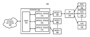
- FIG. 1 illustrates a network 100 , such as an HFC network, including end devices 102 .
- the end device 102 may be DOCSIS Terminal devices, such as cable modems (CMs), modem terminal adapters, MTAs, and embedded cable modems of DOCSIS set-top gateways (eCMs of DSGs), or any other like devices.
- the end devices 102 are connected to a headend 104 of the network 100 via nodes 106 and an RF cascade 103 comprised of multiple amplifiers and passive devices including cabling, taps, splitters, and in-line equalizers.
- a network tap is a hardware device providing access to data within the network 100 .
- the network tap provides the ability to monitor data between two points, for instance components, in the network 100 .
- An impairment contribution estimator 200 may be connected to the network 100 through any network access point including a tap.
- the headend 104 connects to an IP (Internet Protocol) and/or PSTN (Public Switched Telephone Network) network 108 .
- IP Internet Protocol
- PSTN Public Switched Telephone Network
- Data such as TV programs, audio, video and other data, which may be from the network 108 , is sent from the headend 104 to the end devices 102 .
- the end devices 102 may send data upstream towards the headend 104 .
- each of the nodes 106 may be connected to multiple end devices.
- the headend 104 includes a CMTS 110 and optical transceivers 112 which provide optical communications to and from the CMTS 110 through optical fiber to the nodes 106 .
- the nodes 106 connect to the headend 104 , and the headend 104 contains a plurality of CMTS units 110 .
- Each CMTS 110 contains a plurality of transceivers, which communicate with the plurality of end devices 102 .
- each CMTS 110 may have eight or more receivers (e.g., for DOCSIS 2.0), and each receiver may communicate with hundreds of end devices 102 .
- the CMTS may have more than eight receivers (e.g., DOCSIS 3.0 may use 48 receivers).
- FIG. 2 illustrates an architecture of the CMTS 110 , according to an embodiment.
- the CMTS 110 includes a processing unit 114 having a microprocessor 116 that receives information, such as instructions and data, from a RAM 118 and a ROM 120 .
- the processing unit 114 controls the operation of the CMTS 110 and RF communication signals to be sent by the end devices 102 to the CMTS 110 .
- the processing unit 114 is connected to a display 122 , which may display status information such as whether station maintenance (SM) is being performed, or a receiver is in need of load balancing.
- An input keypad 124 may also be connected to the processing unit 114 to permit an operator to provide instructions and process requests.
- SM station maintenance
- the CMTS 110 also includes an RF transceiver (transmitter/receiver) unit 126 having transmitters 128 and receivers 130 providing bi-directional communication capability with the end devices 102 through optical transceivers 112 , nodes 106 and an RF cascade 103 comprised of multiple amplifiers and passive devices including cabling, taps, splitters, and in-line equalizers.
- the CMTS 110 may contain a plurality of RF receivers 130 , such as eight RF receivers and a spare RF receiver. Each of the RF receivers 130 may provide support for a hundred or more end devices 102 .
- the receivers 130 can be BROADCOM 3140 receivers that each includes a demodulator unit 132 and an equalizer 134 to which received RF signals are provided, for instance, for purposes of acquiring equalizer values and burst modulation error ratio (MER) measurements, packet error rate (PER) and bit error rate (BER).
- the equalizer 134 can be a multiple tap linear equalizer (e.g. a twenty-four tap linear equalizer), which also is known as a feed forward equalizer (FFE).
- the equalizer 134 can be integrally contained in the RF receiver, or alternatively, may be provided as a separate device.
- the communication characteristics of each receiver 130 may be stored on ROM 120 or RAM 118 , or may be provided from an external source. Note that the equalizer 134 is in the upstream path, for example, from the end devices 102 towards the network 108 .
- the RF transceiver unit 126 also includes a modulator 136 , which provides the modulated signals to RF transmitters 128 .
- the modulator 136 and demodulator 132 are capable of modulation schemes of various levels of complexity. For example, some upstream DOCSIS 2.0 modulation schemes that may be used in order of level of complexity include, but are not limited to 16 QAM, 32 QAM, 64 QAM and 128 QAM.
- the microprocessor 116 may provide instructions to the end devices 102 as to which modulation scheme is to be used during communication.
- the CMTS 110 also provides instructions for the end devices 102 using a transmit pre-equalization (PRE-EQ) feature in order to compensate for upstream channel impairments.
- the CMTS 110 receives an incoming signal from each of the end devices 102 and compares the incoming signal with an expected signal, which is an ideal response. If the incoming signal received by the CMTS 110 differs from the expected signal, the microprocessor 116 or other processing device performing a PRE-EQ function then determines a set of equalization coefficients (alternately referred to as transmit pre-equalization coefficients) for each of the end devices 102 and instructs the end devices 102 to set their transmit equalization coefficients to the transmit pre-equalization coefficients determined by the PRE-EQ function. The end devices 102 apply the pre-equalization coefficients and then continue to transmit. The CMTS 110 thereafter continues to monitor and compare the incoming signal against the expected signal.
- PRE-EQ transmit pre-equalization
- FIG. 3 illustrates an architecture of an impairment contribution estimator 200 .
- the impairment contribution estimator 200 may be connected to the network 100 through any network access point, for instance through a network access terminal.
- the impairment contribution estimator 200 is configured for estimating impairment contributions and isolating defective network components in the system 100 according to the method 300 below.
- the impairment contribution estimator 200 includes a data storage device 201 , and a testing module 202 .
- the testing module 202 includes an equalization coefficient receiving (ECRC) module 203 , an equalization coefficient resolution (ECRS) module 204 , an impairment level determination (ILD) module 205 , and a cable network plant components isolation (CPCI) module 206 .
- the testing module 201 may also include a modulation configuration (MC) module (not shown).
- MC modulation configuration
- the data storage device 201 is configured to store an impairment threshold for at least one impairment contribution.
- the ECRC module 203 is configured to receive equalization coefficients from the end devices 102 . The equalization coefficients are thereafter stored in the data storage device 201 .
- the ECRS module 204 is configured to resolve the equalization coefficients into the at least one impairment contribution.
- the ILD module 205 is configured to determine whether each of the end devices 102 exceeds the impairment threshold and to group each of the end devices 102 into sets that exceed impairment thresholds as impaired sets or sets that do not exceed impairment thresholds as unimpaired sets.
- the CPCI module 206 is configured to identify cable network plant components associated with each of the ILD sorted sets wherein the cable network plant components are designated as suspect components. cable network plant components are correlated with each set of end devices, for example, based on whether they are used in an upstream or downstream path for an end device.
- the components 202 - 206 are configured to perform the method 300 described with respect to FIG. 5 .
- the components 202 - 206 may comprise software modules, hardware modules, and a combination of software and hardware modules.
- one or more of the modules 202 - 206 comprise circuit components.
- one or more of the modules 202 - 206 comprise software code stored on a computer readable storage medium, which is executable by a processor.
- the impairment contribution estimator 200 depicted in FIG. 3 may include additional components and that some of the components described herein may be removed and/or modified without departing from a scope of the impairment contribution estimator 200 .
- the impairment contribution estimator 200 comprises a part of a network device such as a RF-Sentry application. According to another embodiment, the impairment contribution estimator 200 comprises a part an edge router, such as a part of the advanced spectrum management function of the BSR64000 edge router.
- FIG. 4 illustrates an embodiment of one of the end devices 102 (shown as 102 a ), such as a cable modem.
- the end device 102 a contains a processor 181 which communicates with a RAM 182 and ROM 183 and which controls the general operation of the end device 102 , including applying the pre-equalization coefficients and controlling preamble lengths of communications sent by the end device 102 a in accordance with instructions from the CMTS 110 .
- the end device 102 a also contains a transceiver 186 which provides bidirectional RF communication with the CMTS 110 .
- a demodulator 185 demodulates signals received by the transceiver 186 , and an equalizer 187 biases communications transmitted to the CMTS 110 .
- the equalizer 187 is connected in the upstream path between a transmitter in the transceiver 186 and the CMTS 110 .
- the microprocessor 181 configures the equalizer 187 using the coefficients received from the CMTS 110 to compensate for upstream impairments.
- the end device 102 a also contains a modulator 188 , which modulates signals to be transmitted upstream to the CMTS 110 according to a modulation scheme, which the end device 102 a has been instructed to use by the CMTS 110 .
- the end device 102 a has an attenuator 189 controlled by microprocessor 181 to attenuate signals to be transmitted by the RF transmitter to be within a desired power level.
- the end device 102 a may be a DOCSIS network element, such as a cable modem, to generate a variety of test signals.
- the test signals may be implemented using one of the available upstream DOCSIS bandwidths, e.g. 200 kHz, 400 kHz, 800 kHz, 1600 kHz, 3200 kHz or 6400 kHz.
- Accurate knowledge of the available and/or optimum modulation schemes of the network 100 enables the operator to utilize available resources of their network more efficiently, such as by adding additional end devices to improve portions of the network with the least complex modulation schemes so that those portions may be able to use more complex modulation schemes.
- system 100 may include additional elements not shown and that some of the elements described herein may be removed, substituted and/or modified without departing from the scope of the system 100 . It should also be apparent that one or more of the elements described in the embodiment of FIG. 1 may be optional.
- Some or all of the operations set forth in the method 300 may be contained as one or more computer programs stored in any desired computer readable medium and executed by a processor on a computer system.
- Exemplary computer readable media that may be used to store software operable to implement the present invention include but are not limited to conventional computer system RAM, ROM, EPROM, EEPROM, hard disks, or other data storage devices.
- the impairment contribution estimator 200 retrieves at least one impairment threshold corresponding to an impairment contribution from the data storage 201 .
- the impairment contribution may be selected from the group including GDV, AD, MR and any impairment contribution that may be isolated by analysis of the coefficients as described in detail at step 303 below.
- At least one impairment threshold corresponding to the impairment contribution may be selected from the group comprising an industry standard specification, a customer preferred limit, a PRE-EQ failure limit, a PRE-EQ failure limit less acceptable system margin and, where applicable, a function of signaling characteristics.
- Signaling characteristics include, for instance, RF frequency, QAM modulation level, bandwidth, symbol rate, forward error correction (FEC) settings, and other properties related to signaling.
- the impairment threshold may be selected from the group comprising the industry standard specification (for GDV), the customer preferred limit, the PRE-EQ failure limit, the PRE-EQ failure limit less acceptable system margin and a function of a radio frequency (RF) cascade.
- the function of the RF cascade may comprise a to-be-determined (TBD) value in ns/MHz per RF Amplifier. For instance, a DOCSIS assumption for GDV is 200 ns/MHz.
- the impairment threshold may be any of the industry standard specification. For instance any of a DOCSIS assumption for amplitude ripple of ⁇ 0.5 dB per MHz, the customer preferred limit, the PRE-EQ failure limit, the PRE-EQ failure limit less acceptable system margin and a function of RF frequency and RF amplifier cascade length.
- the impairment contribution may comprise any impairment contribution that may be isolated by analysis of the coefficients, for instance as described at step 303 below.
- the at least one impairment threshold corresponding to the impairment contribution may be thereafter selected in a similar manner as described above with regard to the impairment threshold for AD, MR, and GDV.
- the impairment contribution estimator 200 determines the equalization coefficients currently being used by the end devices 102 for upstream communication.
- the equalization coefficients may be received from the end devices 102 or the CMTS 110 .
- the end devices 102 may comprise at least one of the group comprising DOCSIS terminal devices, including cable modems (CMs), modem terminal adapters, (MTAs), and embedded cable modems of DOCSIS set-top gateways, (eCMs of DSGs).
- CMs cable modems
- MTAs modem terminal adapters
- eCMs of DSGs embedded cable modems of DOCSIS set-top gateways
- the ECRC module 203 may be configured to query the end devices 102 (preferably a DOCSIS 2.0 CM population) using a simple network management protocol (SNMP) query tool such as a modem PRE-EQ response tool.
- the modem PRE-EQ response tool developed by MOTOROLA, is operable to query multiple DOCSIS terminal devices based on an Internet protocol (IP) address list.
- IP Internet protocol
- the modem PRE-EQ response tool is operable to conduct periodic polls of coefficient values and other relevant physical layer (PHY) metrics and to subsequently display the results of the periodic polls and/or to store the results of the periodic polls into a log file for post processing.
- the modem PRE-EQ response tool also provides users with a graphical view of the impulse response or alternately the amplitude response for each CM poll.
- the modem PRE-EQ response tool is operable to establish a baseline of performance, and may be used to identify defective network components based on CM IP addresses of the plurality of end devices.
- the impairment contribution estimator 200 determines whether an impairment problem exists for upstream communications from the end devices 102 .
- the determination is based on an analysis of the coefficients determined from step 302 and may be based on the impairment thresholds determined from step 301 .
- the coefficients are analyzed to determine whether any of the impairment thresholds are exceeded. For example, based on experience, certain coefficient values are associated with certain impairment problems and exceeded impairment thresholds.
- a table may be stored that includes sets of coefficient values (e.g., impairment coefficient signatures) and the type of impairment problem associated with each set of values. This tables of signatures is compared against each of the coefficients determined at step 302 .
- an impairment coefficient signature is found in coefficients determined at step 302 , then the end device using those coefficients is determined to have the particular type of impairment associated with the signature as indicated in the table. Thus, at least two determinations may be made. One determination is whether an impairment problem exists, such as unsatisfactory GDV, AR, MR, etc. Then, if an impairment problem exists, at step 304 , a second determination is made which identifies the type of impairment.
- the ECRS module 204 performs a Fast Fourier Transform (FFT) function on the equalization coefficients for the end devices 102 (e.g. a set of 24 complex coefficients in DOCSIS 2.0), and determines frequency domain information, including a frequency response. For instance, the ECRS module 204 may use a 1024-point FFT to arrange the equalization coefficients for the PRE-EQ baseline and determine the optimal translation of the equalization coefficients.
- the frequency domain information may be interpreted in multiple ways including in terms of magnitude versus frequency, phase versus frequency, and group delay versus frequency. Based on these magnitudes, a determination is made as to the type of impairment problem that exists, if any exists.
- negligible amplitude correction but increased correction for phase and group delay is indicative of a GDV impairment.
- other types of impairments can be determined.
- the end devices 102 are sorted into sets, on increasing levels that sum the DOCSIS PRE-EQ regions for each of the end devices 102 , according to the impairment that the ECRS module 204 is configured to determine.
- the ECRS module 204 may determine which of the end devices 102 experiences the greatest amount of MR impairment contribution by sorting on the levels which result from summing the taps located in the post-tap region of each tap of the 24-tap equalizer of DOCSIS 2.0.
- the ILD module 205 determines the type of impairment for each end device, for example, if the impairment threshold is exceeded for the end device.
- the ILD module 205 groups each of the end devices 102 into impairment level determined (ILD) sets.
- the ILD sets include impaired sets comprising end devices that exceed impairment thresholds and unimpaired sets comprised of end devices that do not exceed impairment thresholds as unimpaired sets.
- the impairment sets may include sets by type of impairment and may indicate the level of impairment for each end device.
- the ILD module 205 determines the relation of the measured impairment contribution to the impairment threshold for each of the impairment contributions. If the impairment contribution exceeds the impairment threshold, the upstream impairments may be at a level at which a customer problem is experienced.
- the ILD module 205 is configured to provide information so that an end user may perform preventive maintenance.
- the ILD module 205 may also be configured to determine a dominant impairment contribution. For instance, the ILD module 205 may analyze the translation of the equalization coefficients of the end devices 102 , and an expected translation of the equalization coefficients for each of the impairment contributions in order to determine the dominant impairment contribution.
- the expected translation of the equalization coefficients for each of the impairment contributions comprises a translation of equalization coefficients for a channel with a single impairment, for instance AD.
- the operation of the ILD module 205 may be enhanced by application of an increased understanding of the different impairment contributions and how they originate in HFC plant. For example, although an MR source has been discussed in the preceding section regarding MRs, combining an understanding of other probable permutations of MR sources with the location of the ILD sets increases the probability of successful isolation of the MR sources. The understanding of probable sources may be used to eliminate possible sources of the impairment contribution and to therefore isolate the source of the impairment contribution. The results may be used to define what impairment levels will likely result in service calls, and thereafter impairment thresholds as defined at step 301 may be determined. Further, the ILD module 205 may be configured to prioritize the impaired sets or prioritize end devices in each set according to level of impairment.
- suspect cable network components are identified that are probable causes for the type of impairment being experienced by an end device. Identification of the suspect components may be based on experience or historical analysis of past impairments and their fixes. For example, the CPCI module 206 identifies cable network plant components associated with each of the impaired sets. This process of identification may be enhanced by consulting data regarding the end devices 102 and network components between each of the plurality of end devices and the CMTS 110 . The CPCI module 206 identifies the cable network components associated with impaired sets as suspect components. The CPCI module 206 then leverages the end devices 102 to isolate those experiencing an impairment problem related to a specific impairment contribution.
- a query of the end devices 102 may reveal that all of the end devices 102 located off a particular node are reporting a MR impairment contribution above the impairment threshold for MR, while the other end devices 102 , unimpaired sets are not reporting a problem.
- the impairment contribution estimator 200 may provide guidance helping cable operators decide the significance of the information that they are analyzing.
- the impairment contribution estimator 200 may contain a checklist of possible sources of the impairment contribution, preferably sorted in order of probability. For instance, inspection of the suspect components may show that the MR impairment contribution source is a combination of tap-to-output port isolation loss and an improperly terminated cable splice at the end of a feed amplifier. By properly terminating the splice, the operator may reduce the MR to negligible amplitudes.
- the impairment contribution estimator 200 may sort the impaired sets into a less impaired set of devices and a more impaired set of devices according to a level of impairment and route traffic to another channel that the impairment contribution estimator 200 indicates is less impaired.
- the steps of the method 300 may be repeated periodically and for each of the end devices 102 or groups of end devices to detect future impairment problems and to ensure that detected impairment problems are eliminated and the improvements are sustainable. If the operator is preparing to upgrade the network 100 to a higher modulation scheme, for instance upgrading from 16-QAM to 64-QAM, the operator may perform the method 300 in order to determine potential problem components. In order to test the network 100 , the operator may configure the network at the higher modulation scheme. Thereafter, the operator may perform the testing process of the method 300 , designating the suspect components as potential upgrade components.
- Embodiments of the present invention interpret equalization coefficients for end devices and identify potential impairments of upstream channels for the end devices based on an analysis of the equalization coefficients. Also, a particular type of impairment problem can be identified based on the analysis of equalization coefficients. Determination of the type of impairment can be coupled with additional information, such as location of the end device or tap, to determine suspect cable network components that may be causing the impairment. Thus, identification of an impairment problem and potential solutions can be determined before a customer problem is experienced and without dispatching technicians to diagnose the problem.
Landscapes
- Engineering & Computer Science (AREA)
- Multimedia (AREA)
- Physics & Mathematics (AREA)
- Electromagnetism (AREA)
- Computer Networks & Wireless Communication (AREA)
- Signal Processing (AREA)
- Cable Transmission Systems, Equalization Of Radio And Reduction Of Echo (AREA)
Abstract
Description
- Cable television networks, including community antenna television (CATV), hybrid fiber-coaxial (HFC), and fiber networks, have been in widespread use for many years and are extensive. The extensive and complex cable networks are often difficult for a cable operator to manage and monitor. A typical cable network generally contains a headend which is usually connected to several nodes which provide bi-directional content to a cable modem termination system (CMTS). In many instances, several nodes may serve a particular area of a town or city. The CMTS contains several receivers, and each receiver connects to several modems of many subscribers. For instance, a single receiver may be connected to hundreds of modems at customer premises. Data may be transmitted downstream to the modems on different frequency bands. The modems communicate to the CMTS via upstream communications on a dedicated frequency band, referred to as a return band.
- Cable networks are also increasingly carrying signals, which require a high quality and reliability of service, such as Voice over IP (VoIP) communications. Any disruption of voice or data traffic is a great inconvenience and often unacceptable to a customer. Various factors may affect the quality of service, including the quality of the upstream channels. One factor that affects the quality of upstream communications is the presence of up-stream channel impairments, such as micro-reflections (MRs) of communication signals, group delay variation (GDV), and amplitude distortion (AD).
- AD is an undesirable variation in the channel's amplitude response. Common forms of AD include tilt, ripple, and roll-off. A common cause of AD is upper return band-edge carriers, aggravated by long reaches of a cable network plant. The long reaches accumulate diplex filters from devices including amplifiers and in-line equalizers. While individually contributing small attenuation versus frequency, the accumulated diplex filters can create appreciable response variation. In a QAM constellation, the amplitude roll-off causes the symbols to spread in a pattern similar in appearance to Additive White Gaussian Noise (AWGN) and causes received symbols to cross decision boundaries, resulting in errors.
- GDV is an undesirable variation in the communication channel's phase response, resulting in distortion of the digital signal phase, or a variation in the propagation of frequency components of the signal across the channel. As is the case for AD, one major cause of GDV in the plant is upper-band-edge operation, combined with long reaches of cable network plant. The reasoning is the same as in the AD case. Note that filtering functions typically induce nonlinear phase responses as the band edges are approached, so the combination of AD and GDV in the same band region is perfectly expected, with the understanding that diplex filtering is the cause. Different filter functions induce different GDV responses, in a similar manner that different filter functions induce different stop-band characteristics. It is typical that the sharper the roll-off, such as would be the case for long cascades, the worse the GDV will be. In a QAM constellation, GDV causes the symbols to spread in a pattern similar to AWGN and AD and causes received symbols to cross decision boundaries, resulting in errors. 16-QAM is less sensitive to GDV than 64-QAM because of reduced decision boundary size of 64-QAM.
- As seen by a receiver, a MR is a copy of the transmitted signal, arriving late and with reduced amplitude. The result of the additional copy is the typically seen by end users as image ghosting in analog video reception, whereas for digital communications the result is inter-symbol interference (ISI). MR sources are composed of pairs of hybrid fiber-coaxial (HFC) components separated by a distance of cable. The HFC components, also referred to as cable network components, facilitate the propagation of signal copies in a variety of ways including return loss, isolation, mixing, and combining. For instance, the MR may arise if a length of cable separates two devices with poor return loss, acting as signal reflectors. The reflector return loss and the loss between the reflectors determine the amplitude of the MR. Any HFC component, for instance a cable modem (CM), has the potential to act as a signal reflector. Note that the CM typically has as a design limit of 6 dB return loss, meaning it may reflect up to 25% of its incident power. In the cable network plant, components other then the CM typically reflect a lower percentage of incident power because the design limits are typically significantly better. However, as the cable network plant ages and elements that contribute to good RF matching degrade, for instance connectors, cable, splitters, and interfaces on printed circuit boards (PCBs), the reflected percentage of incident power increases.
- These upstream channel impairments are known to be mitigated by the fundamental digital communications receiver function of equalization. During equalization, an equalizer generates coefficient information that is used to create an equalizing filter, with an inverse channel response, canceling distortion in the channel caused by the upstream channel impairments. The equalization coefficients in Data Over Cable Service Interface Specification (DOCSIS) 2.0 and DOCSIS 3.0 are 24 symbol-spaced coefficients (also referred to as taps). Equalization is part of virtually all modern telecommunications platforms, and is instrumental in proper return operation for all DOCSIS systems.
- In order to offer higher data rates to subscribers in the competitive world of high-speed data and Internet access, operators must take advantage of the throughput benefits gained from leveraging more complex digital modulation schemes, such as 32-QAM and 64-QAM. Use of 32-QAM allows, for example, a 20 Mbps 16-QAM upstream to become a 25 Mbps upstream. On the other hand, for 64-QAM, it allows a 16-QAM, 20 Mbps upstream channel to become a 30 Mbps channel. This represents a 25-50% throughput improvement. Unfortunately, channels using these digital modulation schemes are also considerably more sensitive to digital communication channel impairments, including the upstream impairments described above, than the 16-QAM channels they are often replacing in the return band.
- Given the potential problems that can be caused by the upstream impairments, upstream channels are one of the most challenging digital communication channels to manage and fully exploit. Operators prefer to ensure that capacity associated with the upstream channel, or as much of the capacity as possible, is realized for services and revenue. To do so requires a thorough understanding of a diverse set of HFC and digital communications variables. More importantly, variables that did not matter very much for 16-QAM operation now become not just relevant, but critical to understand for successful deployment of 64-QAM, and to a lesser extent, 32-QAM. Accurately diagnosing upstream issues typically requires technicians or engineers to be at multiple locations within a HFC plant and simultaneously inject test signals at the suspected device locations. This diagnostic process requires extensive manual effort, often requiring rolling trucks to remote locations within a plant or specialized test equipment. The diagnostic process is also time consuming and costly.
- According to an embodiment, a system estimates impairment contributions for upstream communications in a cable television system. The system receives equalization coefficients used by end devices in the cable television system. The equalization coefficients are used by equalizers to mitigate distortion in upstream channels for the end devices. The system analyzes the coefficients based on impairment thresholds to determine whether impairment problems exist in the upstream channels and to identify the types of impairment problems that exist. Other embodiments include computer-implemented methods estimating impairment contributions for upstream communications based on received equalization coefficients and impairment thresholds.
- Embodiments interpret equalization coefficients for end devices and identify potential impairments of upstream channels for the end devices based on an analysis of the equalization coefficients. Also, a particular type of impairment problem can be identified based on the analysis of equalization coefficients. Determination of the type of impairment can be coupled with additional information, such as location of the end device or tap, to determine suspect cable network components that may be causing the impairment. Thus, identification of an impairment problem and potential solutions can be determined before a customer problem is experienced and without dispatching technicians to diagnose the problem.
- Features of the present invention will become apparent to those skilled in the art from the following description with reference to the figures, in which:
-
FIG. 1 illustrates a block diagram of a cable network, according to an embodiment of the invention; -
FIG. 2 illustrates a CMTS architecture, according to an embodiment of the invention; -
FIG. 3 illustrates a device for estimating impairment contributions and isolating defective network components, according to an embodiment of the invention; and -
FIG. 4 illustrates a device for estimating impairment contributions and isolating defective network components, according to an embodiment of the invention; -
FIG. 5 illustrates a method for estimating impairment contributions and isolating defective network components using a plurality of end devices, according to an embodiment of the invention; and -
FIG. 6 shows a block diagram of a computer system that may be used for estimating impairment contributions and isolating defective network components, according to an embodiment of the invention. - For simplicity and illustrative purposes, the present invention is described by referring mainly to exemplary embodiments thereof. In the following description, numerous specific details are set forth to provide a thorough understanding of the present invention. However, it will be apparent to one of ordinary skill in the art that the present invention may be practiced without limitation to these specific details. In other instances, well known methods and structures have not been described in detail to avoid unnecessarily obscuring the present invention.
- The abbreviation “decibels relative to a carrier (dBc)” refers to a measure of the power ratio of a signal to a carrier signal, and is expressed in decibels. Note “dB” refers to a decibel, “ns” refers to a nanosecond, and “MHz” refers to a megahertz.
- The term “equalization coefficient” refers to complex tap values used to create an equalizing filter with an inverse channel response.
- The term “impairment contribution” refers to causes of impairment in an upstream hybrid fiber coaxial (HFC) plant.
- The term “micro-reflection (MR)” refers to an impairment contribution wherein a copy of a communication signal is reflected back onto itself, with a time delay. Significant MRs can degrade upstream HFC plant performance.
- The term “group delay variation (GDV)” refers to an impairment contribution wherein different frequency components of a signal propagate through a network component with different time delays.
- The term “cable network plant components” refers to any component that may cause impairment in an upstream channel in the cable network. The components may be components of an HFC network, and may be active or passive components. The upstream channel may be a channel between a modem and a CMTS or another upstream channel in the cable network.
-
FIG. 1 illustrates anetwork 100, such as an HFC network, includingend devices 102. Theend device 102 may be DOCSIS Terminal devices, such as cable modems (CMs), modem terminal adapters, MTAs, and embedded cable modems of DOCSIS set-top gateways (eCMs of DSGs), or any other like devices. Theend devices 102 are connected to aheadend 104 of thenetwork 100 vianodes 106 and anRF cascade 103 comprised of multiple amplifiers and passive devices including cabling, taps, splitters, and in-line equalizers. A network tap is a hardware device providing access to data within thenetwork 100. The network tap provides the ability to monitor data between two points, for instance components, in thenetwork 100. Animpairment contribution estimator 200, shown inFIG. 3 , may be connected to thenetwork 100 through any network access point including a tap. Theheadend 104 connects to an IP (Internet Protocol) and/or PSTN (Public Switched Telephone Network)network 108. Data, such as TV programs, audio, video and other data, which may be from thenetwork 108, is sent from theheadend 104 to theend devices 102. In addition, theend devices 102 may send data upstream towards theheadend 104. Although not shown, each of thenodes 106 may be connected to multiple end devices. - As illustrated in
FIG. 1 , theheadend 104 includes aCMTS 110 andoptical transceivers 112 which provide optical communications to and from theCMTS 110 through optical fiber to thenodes 106. Typically, thenodes 106 connect to theheadend 104, and theheadend 104 contains a plurality ofCMTS units 110. EachCMTS 110 contains a plurality of transceivers, which communicate with the plurality ofend devices 102. For example, eachCMTS 110 may have eight or more receivers (e.g., for DOCSIS 2.0), and each receiver may communicate with hundreds ofend devices 102. The CMTS may have more than eight receivers (e.g., DOCSIS 3.0 may use 48 receivers). -
FIG. 2 illustrates an architecture of theCMTS 110, according to an embodiment. As illustrated, theCMTS 110 includes aprocessing unit 114 having amicroprocessor 116 that receives information, such as instructions and data, from aRAM 118 and aROM 120. Theprocessing unit 114 controls the operation of theCMTS 110 and RF communication signals to be sent by theend devices 102 to theCMTS 110. Theprocessing unit 114 is connected to adisplay 122, which may display status information such as whether station maintenance (SM) is being performed, or a receiver is in need of load balancing. Aninput keypad 124 may also be connected to theprocessing unit 114 to permit an operator to provide instructions and process requests. - The
CMTS 110 also includes an RF transceiver (transmitter/receiver)unit 126 havingtransmitters 128 andreceivers 130 providing bi-directional communication capability with theend devices 102 throughoptical transceivers 112,nodes 106 and anRF cascade 103 comprised of multiple amplifiers and passive devices including cabling, taps, splitters, and in-line equalizers. TheCMTS 110 may contain a plurality ofRF receivers 130, such as eight RF receivers and a spare RF receiver. Each of theRF receivers 130 may provide support for a hundred ormore end devices 102. - By way of example, the
receivers 130 can be BROADCOM 3140 receivers that each includes ademodulator unit 132 and anequalizer 134 to which received RF signals are provided, for instance, for purposes of acquiring equalizer values and burst modulation error ratio (MER) measurements, packet error rate (PER) and bit error rate (BER). Theequalizer 134 can be a multiple tap linear equalizer (e.g. a twenty-four tap linear equalizer), which also is known as a feed forward equalizer (FFE). Theequalizer 134 can be integrally contained in the RF receiver, or alternatively, may be provided as a separate device. The communication characteristics of eachreceiver 130 may be stored onROM 120 orRAM 118, or may be provided from an external source. Note that theequalizer 134 is in the upstream path, for example, from theend devices 102 towards thenetwork 108. - The
RF transceiver unit 126 also includes amodulator 136, which provides the modulated signals toRF transmitters 128. Themodulator 136 anddemodulator 132 are capable of modulation schemes of various levels of complexity. For example, some upstream DOCSIS 2.0 modulation schemes that may be used in order of level of complexity include, but are not limited to 16 QAM, 32 QAM, 64 QAM and 128 QAM. Themicroprocessor 116 may provide instructions to theend devices 102 as to which modulation scheme is to be used during communication. - The
CMTS 110 also provides instructions for theend devices 102 using a transmit pre-equalization (PRE-EQ) feature in order to compensate for upstream channel impairments. TheCMTS 110 receives an incoming signal from each of theend devices 102 and compares the incoming signal with an expected signal, which is an ideal response. If the incoming signal received by theCMTS 110 differs from the expected signal, themicroprocessor 116 or other processing device performing a PRE-EQ function then determines a set of equalization coefficients (alternately referred to as transmit pre-equalization coefficients) for each of theend devices 102 and instructs theend devices 102 to set their transmit equalization coefficients to the transmit pre-equalization coefficients determined by the PRE-EQ function. Theend devices 102 apply the pre-equalization coefficients and then continue to transmit. TheCMTS 110 thereafter continues to monitor and compare the incoming signal against the expected signal. -
FIG. 3 illustrates an architecture of animpairment contribution estimator 200. Theimpairment contribution estimator 200 may be connected to thenetwork 100 through any network access point, for instance through a network access terminal. Theimpairment contribution estimator 200 is configured for estimating impairment contributions and isolating defective network components in thesystem 100 according to themethod 300 below. As such, theimpairment contribution estimator 200 includes adata storage device 201, and atesting module 202. Thetesting module 202 includes an equalization coefficient receiving (ECRC)module 203, an equalization coefficient resolution (ECRS)module 204, an impairment level determination (ILD)module 205, and a cable network plant components isolation (CPCI)module 206. Thetesting module 201 may also include a modulation configuration (MC) module (not shown). - The
data storage device 201 is configured to store an impairment threshold for at least one impairment contribution. TheECRC module 203 is configured to receive equalization coefficients from theend devices 102. The equalization coefficients are thereafter stored in thedata storage device 201. TheECRS module 204 is configured to resolve the equalization coefficients into the at least one impairment contribution. TheILD module 205 is configured to determine whether each of theend devices 102 exceeds the impairment threshold and to group each of theend devices 102 into sets that exceed impairment thresholds as impaired sets or sets that do not exceed impairment thresholds as unimpaired sets. TheCPCI module 206 is configured to identify cable network plant components associated with each of the ILD sorted sets wherein the cable network plant components are designated as suspect components. cable network plant components are correlated with each set of end devices, for example, based on whether they are used in an upstream or downstream path for an end device. - The components 202-206 are configured to perform the
method 300 described with respect toFIG. 5 . The components 202-206 may comprise software modules, hardware modules, and a combination of software and hardware modules. Thus, in one embodiment, one or more of the modules 202-206 comprise circuit components. In another embodiment, one or more of the modules 202-206 comprise software code stored on a computer readable storage medium, which is executable by a processor. It should be understood that theimpairment contribution estimator 200 depicted inFIG. 3 may include additional components and that some of the components described herein may be removed and/or modified without departing from a scope of theimpairment contribution estimator 200. According to an embodiment, theimpairment contribution estimator 200 comprises a part of a network device such as a RF-Sentry application. According to another embodiment, theimpairment contribution estimator 200 comprises a part an edge router, such as a part of the advanced spectrum management function of the BSR64000 edge router. -
FIG. 4 illustrates an embodiment of one of the end devices 102 (shown as 102 a), such as a cable modem. Theend device 102 a contains aprocessor 181 which communicates with aRAM 182 andROM 183 and which controls the general operation of theend device 102, including applying the pre-equalization coefficients and controlling preamble lengths of communications sent by theend device 102 a in accordance with instructions from theCMTS 110. Theend device 102 a also contains atransceiver 186 which provides bidirectional RF communication with theCMTS 110. A demodulator 185 demodulates signals received by thetransceiver 186, and anequalizer 187 biases communications transmitted to theCMTS 110. For example, theequalizer 187 is connected in the upstream path between a transmitter in thetransceiver 186 and theCMTS 110. Themicroprocessor 181 configures theequalizer 187 using the coefficients received from theCMTS 110 to compensate for upstream impairments. Theend device 102 a also contains amodulator 188, which modulates signals to be transmitted upstream to theCMTS 110 according to a modulation scheme, which theend device 102 a has been instructed to use by theCMTS 110. In addition, theend device 102 a has anattenuator 189 controlled bymicroprocessor 181 to attenuate signals to be transmitted by the RF transmitter to be within a desired power level. Those of skill in the art will appreciate that the components ofend device 102 a have been illustrated separately only for discussion purposes and that various components may be combined in practice. - By way of example, the
end device 102 a may be a DOCSIS network element, such as a cable modem, to generate a variety of test signals. Accordingly, the test signals may be implemented using one of the available upstream DOCSIS bandwidths, e.g. 200 kHz, 400 kHz, 800 kHz, 1600 kHz, 3200 kHz or 6400 kHz. - Accurate knowledge of the available and/or optimum modulation schemes of the
network 100 enables the operator to utilize available resources of their network more efficiently, such as by adding additional end devices to improve portions of the network with the least complex modulation schemes so that those portions may be able to use more complex modulation schemes. - It will be apparent that the
system 100 may include additional elements not shown and that some of the elements described herein may be removed, substituted and/or modified without departing from the scope of thesystem 100. It should also be apparent that one or more of the elements described in the embodiment ofFIG. 1 may be optional. - An example of a method in which the
system 100 and theimpairment contribution estimator 200 may be employed for estimating impairment contributions and isolating defective network components using theend devices 102 will now be described with respect to the following flow diagram of themethod 300 depicted inFIG. 5 . It should be apparent to those of ordinary skill in the art that themethod 300 represents a generalized illustration and that other steps may be added or existing steps may be removed, modified or rearranged without departing from the scopes of themethod 300. In addition, themethod 300 is described with respect to thesystem 100 by way of example and not limitation, and themethod 300 may be used in other systems. - Some or all of the operations set forth in the
method 300 may be contained as one or more computer programs stored in any desired computer readable medium and executed by a processor on a computer system. Exemplary computer readable media that may be used to store software operable to implement the present invention include but are not limited to conventional computer system RAM, ROM, EPROM, EEPROM, hard disks, or other data storage devices. - At
step 301, as shown inFIG. 5 , theimpairment contribution estimator 200 retrieves at least one impairment threshold corresponding to an impairment contribution from thedata storage 201. The impairment contribution may be selected from the group including GDV, AD, MR and any impairment contribution that may be isolated by analysis of the coefficients as described in detail atstep 303 below. At least one impairment threshold corresponding to the impairment contribution may be selected from the group comprising an industry standard specification, a customer preferred limit, a PRE-EQ failure limit, a PRE-EQ failure limit less acceptable system margin and, where applicable, a function of signaling characteristics. Signaling characteristics include, for instance, RF frequency, QAM modulation level, bandwidth, symbol rate, forward error correction (FEC) settings, and other properties related to signaling. - To illustrate, where the impairment contribution is GDV, the impairment threshold may be selected from the group comprising the industry standard specification (for GDV), the customer preferred limit, the PRE-EQ failure limit, the PRE-EQ failure limit less acceptable system margin and a function of a radio frequency (RF) cascade. The function of the RF cascade may comprise a to-be-determined (TBD) value in ns/MHz per RF Amplifier. For instance, a DOCSIS assumption for GDV is 200 ns/MHz.
- Next, where the impairment contribution is AD, the impairment threshold may be any of the industry standard specification. For instance any of a DOCSIS assumption for amplitude ripple of ≦0.5 dB per MHz, the customer preferred limit, the PRE-EQ failure limit, the PRE-EQ failure limit less acceptable system margin and a function of RF frequency and RF amplifier cascade length.
- Similarly, where the impairment contribution is MR, the impairment threshold may be any of the industry standard specification. For instance a DOCSIS assumption of −10 dBc@<=0.5 μsec (alternately −20 dBc@<=1.0 μsec, or −30 dBc@>1.0 μsec) for a single dominant MR, the customer preferred limit, the PRE-EQ failure limit, the PRE-EQ failure limit less acceptable system margin, and a function of RF frequency. Simulation and tests may be performed to determine the highest MR impairment level that is correctable using DOCSIS 2.0/3.0 PRE-EQ. The results of these simulations may be used to define the PRE-EQ failure limit.
- Further, the impairment contribution may comprise any impairment contribution that may be isolated by analysis of the coefficients, for instance as described at
step 303 below. After the impairment contribution has been isolated, the at least one impairment threshold corresponding to the impairment contribution may be thereafter selected in a similar manner as described above with regard to the impairment threshold for AD, MR, and GDV. - At
step 302, theimpairment contribution estimator 200 determines the equalization coefficients currently being used by theend devices 102 for upstream communication. The equalization coefficients may be received from theend devices 102 or theCMTS 110. Theend devices 102 may comprise at least one of the group comprising DOCSIS terminal devices, including cable modems (CMs), modem terminal adapters, (MTAs), and embedded cable modems of DOCSIS set-top gateways, (eCMs of DSGs). The resolution of the 24-tap equalizer of DOCSIS 2.0 more effectively identifies impairments, compared to the 8-tap equalizer of DOCSIS 1.1. In a current HFC plant, in order to more effectively identify impairments, the majority of theend devices 102 are required to support at least DOCSIS 2.0 with the pre-equalization feature enabled. - The
ECRC module 203 may be configured to query the end devices 102 (preferably a DOCSIS 2.0 CM population) using a simple network management protocol (SNMP) query tool such as a modem PRE-EQ response tool. The modem PRE-EQ response tool, developed by MOTOROLA, is operable to query multiple DOCSIS terminal devices based on an Internet protocol (IP) address list. The modem PRE-EQ response tool is operable to conduct periodic polls of coefficient values and other relevant physical layer (PHY) metrics and to subsequently display the results of the periodic polls and/or to store the results of the periodic polls into a log file for post processing. The modem PRE-EQ response tool also provides users with a graphical view of the impulse response or alternately the amplitude response for each CM poll. The modem PRE-EQ response tool is operable to establish a baseline of performance, and may be used to identify defective network components based on CM IP addresses of the plurality of end devices. - At
step 303, theimpairment contribution estimator 200 determines whether an impairment problem exists for upstream communications from theend devices 102. The determination is based on an analysis of the coefficients determined fromstep 302 and may be based on the impairment thresholds determined fromstep 301. There may be multiple techniques for determining whether an impairment problem exists. In one embodiment, the coefficients are analyzed to determine whether any of the impairment thresholds are exceeded. For example, based on experience, certain coefficient values are associated with certain impairment problems and exceeded impairment thresholds. A table may be stored that includes sets of coefficient values (e.g., impairment coefficient signatures) and the type of impairment problem associated with each set of values. This tables of signatures is compared against each of the coefficients determined atstep 302. If an impairment coefficient signature is found in coefficients determined atstep 302, then the end device using those coefficients is determined to have the particular type of impairment associated with the signature as indicated in the table. Thus, at least two determinations may be made. One determination is whether an impairment problem exists, such as unsatisfactory GDV, AR, MR, etc. Then, if an impairment problem exists, atstep 304, a second determination is made which identifies the type of impairment. - According to an embodiment, at
step 303, to determine if an impairment problem exists, theECRS module 204 performs a Fast Fourier Transform (FFT) function on the equalization coefficients for the end devices 102 (e.g. a set of 24 complex coefficients in DOCSIS 2.0), and determines frequency domain information, including a frequency response. For instance, theECRS module 204 may use a 1024-point FFT to arrange the equalization coefficients for the PRE-EQ baseline and determine the optimal translation of the equalization coefficients. The frequency domain information may be interpreted in multiple ways including in terms of magnitude versus frequency, phase versus frequency, and group delay versus frequency. Based on these magnitudes, a determination is made as to the type of impairment problem that exists, if any exists. For example, negligible amplitude correction but increased correction for phase and group delay is indicative of a GDV impairment. Similarly, other types of impairments can be determined. For example, theend devices 102 are sorted into sets, on increasing levels that sum the DOCSIS PRE-EQ regions for each of theend devices 102, according to the impairment that theECRS module 204 is configured to determine. For example, theECRS module 204 may determine which of theend devices 102 experiences the greatest amount of MR impairment contribution by sorting on the levels which result from summing the taps located in the post-tap region of each tap of the 24-tap equalizer of DOCSIS 2.0. - At
step 304, theILD module 205 determines the type of impairment for each end device, for example, if the impairment threshold is exceeded for the end device. In one embodiment, theILD module 205 groups each of theend devices 102 into impairment level determined (ILD) sets. The ILD sets include impaired sets comprising end devices that exceed impairment thresholds and unimpaired sets comprised of end devices that do not exceed impairment thresholds as unimpaired sets. Furthermore, the impairment sets may include sets by type of impairment and may indicate the level of impairment for each end device. In one embodiment, theILD module 205 determines the relation of the measured impairment contribution to the impairment threshold for each of the impairment contributions. If the impairment contribution exceeds the impairment threshold, the upstream impairments may be at a level at which a customer problem is experienced. Alternately, if the impairment threshold has an acceptable system margin, theILD module 205 is configured to provide information so that an end user may perform preventive maintenance. TheILD module 205 may also be configured to determine a dominant impairment contribution. For instance, theILD module 205 may analyze the translation of the equalization coefficients of theend devices 102, and an expected translation of the equalization coefficients for each of the impairment contributions in order to determine the dominant impairment contribution. The expected translation of the equalization coefficients for each of the impairment contributions comprises a translation of equalization coefficients for a channel with a single impairment, for instance AD. - The operation of the
ILD module 205 may be enhanced by application of an increased understanding of the different impairment contributions and how they originate in HFC plant. For example, although an MR source has been discussed in the preceding section regarding MRs, combining an understanding of other probable permutations of MR sources with the location of the ILD sets increases the probability of successful isolation of the MR sources. The understanding of probable sources may be used to eliminate possible sources of the impairment contribution and to therefore isolate the source of the impairment contribution. The results may be used to define what impairment levels will likely result in service calls, and thereafter impairment thresholds as defined atstep 301 may be determined. Further, theILD module 205 may be configured to prioritize the impaired sets or prioritize end devices in each set according to level of impairment. - At step 305, suspect cable network components are identified that are probable causes for the type of impairment being experienced by an end device. Identification of the suspect components may be based on experience or historical analysis of past impairments and their fixes. For example, the
CPCI module 206 identifies cable network plant components associated with each of the impaired sets. This process of identification may be enhanced by consulting data regarding theend devices 102 and network components between each of the plurality of end devices and theCMTS 110. TheCPCI module 206 identifies the cable network components associated with impaired sets as suspect components. TheCPCI module 206 then leverages theend devices 102 to isolate those experiencing an impairment problem related to a specific impairment contribution. For example, a query of theend devices 102 may reveal that all of theend devices 102 located off a particular node are reporting a MR impairment contribution above the impairment threshold for MR, while theother end devices 102, unimpaired sets are not reporting a problem. - At
step 306, corrective action is taken. For example, the operator physically inspects all suspect components isolated at step 305 and repairs and replaces as necessary the defective components. Theimpairment contribution estimator 200 may provide guidance helping cable operators decide the significance of the information that they are analyzing. Theimpairment contribution estimator 200 may contain a checklist of possible sources of the impairment contribution, preferably sorted in order of probability. For instance, inspection of the suspect components may show that the MR impairment contribution source is a combination of tap-to-output port isolation loss and an improperly terminated cable splice at the end of a feed amplifier. By properly terminating the splice, the operator may reduce the MR to negligible amplitudes. Alternately, theimpairment contribution estimator 200 may sort the impaired sets into a less impaired set of devices and a more impaired set of devices according to a level of impairment and route traffic to another channel that theimpairment contribution estimator 200 indicates is less impaired. - The steps of the
method 300 may be repeated periodically and for each of theend devices 102 or groups of end devices to detect future impairment problems and to ensure that detected impairment problems are eliminated and the improvements are sustainable. If the operator is preparing to upgrade thenetwork 100 to a higher modulation scheme, for instance upgrading from 16-QAM to 64-QAM, the operator may perform themethod 300 in order to determine potential problem components. In order to test thenetwork 100, the operator may configure the network at the higher modulation scheme. Thereafter, the operator may perform the testing process of themethod 300, designating the suspect components as potential upgrade components. - Although described specifically throughout the entirety of the instant disclosure, representative embodiments of the present invention have utility over a wide range of applications, and the above discussion is not intended and should not be construed to be limiting, but is offered as an illustrative discussion of aspects of the invention.
- Embodiments of the present invention interpret equalization coefficients for end devices and identify potential impairments of upstream channels for the end devices based on an analysis of the equalization coefficients. Also, a particular type of impairment problem can be identified based on the analysis of equalization coefficients. Determination of the type of impairment can be coupled with additional information, such as location of the end device or tap, to determine suspect cable network components that may be causing the impairment. Thus, identification of an impairment problem and potential solutions can be determined before a customer problem is experienced and without dispatching technicians to diagnose the problem.
- What has been described and illustrated herein are embodiments of the invention along with some of their variations. The terms, descriptions and figures used herein are set forth by way of illustration only and are not meant as limitations. Those skilled in the art will recognize that many variations are possible within the spirit and scope of the invention, wherein the invention is intended to be defined by the following claims—and their equivalents—in which all terms are meant in their broadest reasonable sense unless otherwise indicated.
Claims (20)
Priority Applications (1)
| Application Number | Priority Date | Filing Date | Title |
|---|---|---|---|
| US12/565,185 US8526485B2 (en) | 2009-09-23 | 2009-09-23 | Using equalization coefficients of end devices in a cable television network to determine and diagnose impairments in upstream channels |
Applications Claiming Priority (1)
| Application Number | Priority Date | Filing Date | Title |
|---|---|---|---|
| US12/565,185 US8526485B2 (en) | 2009-09-23 | 2009-09-23 | Using equalization coefficients of end devices in a cable television network to determine and diagnose impairments in upstream channels |
Publications (2)
| Publication Number | Publication Date |
|---|---|
| US20110069745A1 true US20110069745A1 (en) | 2011-03-24 |
| US8526485B2 US8526485B2 (en) | 2013-09-03 |
Family
ID=43756591
Family Applications (1)
| Application Number | Title | Priority Date | Filing Date |
|---|---|---|---|
| US12/565,185 Active 2031-05-23 US8526485B2 (en) | 2009-09-23 | 2009-09-23 | Using equalization coefficients of end devices in a cable television network to determine and diagnose impairments in upstream channels |
Country Status (1)
| Country | Link |
|---|---|
| US (1) | US8526485B2 (en) |
Cited By (37)
| Publication number | Priority date | Publication date | Assignee | Title |
|---|---|---|---|---|
| US20120287796A1 (en) * | 2011-05-09 | 2012-11-15 | Cox Communications, Inc. | Systems and methods for assigning customers to groups for the transmission of broadband data signals |
| US20120288067A1 (en) * | 2011-05-09 | 2012-11-15 | Cox Communications, Inc. | Systems and methods for assigning a customer device to a group of customer devices for the transmission of broadband data signals |
| US20130070584A1 (en) * | 2011-09-15 | 2013-03-21 | Michael D. Hutchison | Network impairment unit for concurrent delay and packet queue impairments |
| CN103152648A (en) * | 2013-02-27 | 2013-06-12 | 深圳创维-Rgb电子有限公司 | Method, device and system for processing non-standard signal |
| US8516532B2 (en) | 2009-07-28 | 2013-08-20 | Motorola Mobility Llc | IP video delivery using flexible channel bonding |
| US8526485B2 (en) | 2009-09-23 | 2013-09-03 | General Instrument Corporation | Using equalization coefficients of end devices in a cable television network to determine and diagnose impairments in upstream channels |
| US8537972B2 (en) | 2006-12-07 | 2013-09-17 | General Instrument Corporation | Method and apparatus for determining micro-reflections in a network |
| US20130290783A1 (en) * | 2012-04-27 | 2013-10-31 | General Instrument Corporation | Estimating a Severity Level of a Network Fault |
| US8576705B2 (en) | 2011-11-18 | 2013-11-05 | General Instrument Corporation | Upstream channel bonding partial service using spectrum management |
| US8594118B2 (en) | 2006-03-24 | 2013-11-26 | General Instrument Corporation | Method and apparatus for configuring logical channels in a network |
| US8654640B2 (en) | 2010-12-08 | 2014-02-18 | General Instrument Corporation | System and method for IP video delivery using distributed flexible channel bonding |
| US20140173095A1 (en) * | 2012-12-19 | 2014-06-19 | Hewlett-Packard Development Company, L.P. | Triggering a high availability feature in response to detecting impairment of client experience |
| US8837302B2 (en) | 2012-04-27 | 2014-09-16 | Motorola Mobility Llc | Mapping a network fault |
| US8867371B2 (en) | 2012-04-27 | 2014-10-21 | Motorola Mobility Llc | Estimating physical locations of network faults |
| US8937992B2 (en) | 2011-08-30 | 2015-01-20 | General Instrument Corporation | Method and apparatus for updating equalization coefficients of adaptive pre-equalizers |
| US9003460B2 (en) * | 2012-04-27 | 2015-04-07 | Google Technology Holdings LLC | Network monitoring with estimation of network path to network element location |
| US9025469B2 (en) | 2013-03-15 | 2015-05-05 | Arris Technology, Inc. | Method for estimating cable plant topology |
| US9042236B2 (en) | 2013-03-15 | 2015-05-26 | Arris Technology, Inc. | Method using equalization data to determine defects in a cable plant |
| US20150148089A1 (en) * | 2012-04-25 | 2015-05-28 | Intel Mobile Communications GmbH | Communication devices and methods for operating a communication device |
| US9065731B2 (en) | 2012-05-01 | 2015-06-23 | Arris Technology, Inc. | Ensure upstream channel quality measurement stability in an upstream channel bonding system using T4 timeout multiplier |
| US9088355B2 (en) | 2006-03-24 | 2015-07-21 | Arris Technology, Inc. | Method and apparatus for determining the dynamic range of an optical link in an HFC network |
| US9113181B2 (en) | 2011-12-13 | 2015-08-18 | Arris Technology, Inc. | Dynamic channel bonding partial service triggering |
| US9136943B2 (en) | 2012-07-30 | 2015-09-15 | Arris Technology, Inc. | Method of characterizing impairments detected by equalization on a channel of a network |
| US9137164B2 (en) | 2012-11-15 | 2015-09-15 | Arris Technology, Inc. | Upstream receiver integrity assessment for modem registration |
| US9197886B2 (en) | 2013-03-13 | 2015-11-24 | Arris Enterprises, Inc. | Detecting plant degradation using peer-comparison |
| US9203639B2 (en) | 2012-12-27 | 2015-12-01 | Arris Technology, Inc. | Dynamic load balancing under partial service conditions |
| US20160037366A1 (en) * | 2014-08-01 | 2016-02-04 | Cox Communications, Inc. | Detection and reporting of network impairments |
| US20160380871A1 (en) * | 2011-06-30 | 2016-12-29 | Viavi Solutions Inc. | Testing an upstream path of a cable network |
| US20180097716A1 (en) * | 2014-07-11 | 2018-04-05 | Cable Television Laboratories, Inc. | Edge analytics |
| RU2653289C1 (en) * | 2016-12-07 | 2018-05-07 | Владимир Леонидович Карякин | Method for increasing quality of data transmission channel in iptv system by ber rate in tv broadcasting mode and device for its implementation |
| EP3334092A1 (en) * | 2016-12-07 | 2018-06-13 | Cisco Technology, Inc. | Radio frequency signal fault signature isolation in cable network environments |
| CN108173703A (en) * | 2016-04-25 | 2018-06-15 | 思科技术公司 | Radiofrequency signal fault signature isolation in cable system environment |
| US10348554B2 (en) * | 2016-04-25 | 2019-07-09 | Cisco Technology, Inc. | Hybrid fibre coaxial fault locationing in cable network environments |
| US10477199B2 (en) | 2013-03-15 | 2019-11-12 | Arris Enterprises Llc | Method for identifying and prioritizing fault location in a cable plant |
| US10721539B1 (en) * | 2013-03-14 | 2020-07-21 | CSC Holdings, LLC | Detection of impairments in a network system |
| US11164551B2 (en) | 2019-02-28 | 2021-11-02 | Clifford W. Chase | Amplifier matching in a digital amplifier modeling system |
| US11502932B2 (en) | 2019-05-17 | 2022-11-15 | Keysight Technologies, Inc. | Indirect testing using impairment rules |
Families Citing this family (5)
| Publication number | Priority date | Publication date | Assignee | Title |
|---|---|---|---|---|
| US8249540B1 (en) | 2008-08-07 | 2012-08-21 | Hypres, Inc. | Two stage radio frequency interference cancellation system and method |
| US9735867B2 (en) | 2014-04-25 | 2017-08-15 | Arris Enterprises Llc | Microreflection delay estimation in a CATV network |
| US9237040B1 (en) | 2015-03-10 | 2016-01-12 | Cisco Technologies, Inc. | Pre-equalization enhancement for telecommunication networks |
| US10367699B2 (en) | 2016-04-25 | 2019-07-30 | Cisco Technology, Inc. | Network architecture for predictive services management in cable network environments |
| JP7294452B2 (en) * | 2019-12-11 | 2023-06-20 | 日本電信電話株式会社 | Optical communication state estimation method, device and program |
Citations (95)
| Publication number | Priority date | Publication date | Assignee | Title |
|---|---|---|---|---|
| US3838221A (en) * | 1971-08-11 | 1974-09-24 | Communications Satellite Corp | Tdma satellite communications system having special reference bursts |
| US4245342A (en) * | 1979-01-10 | 1981-01-13 | Intech Laboratories, Inc. | One-for-n modem control apparatus |
| US4385392A (en) * | 1981-07-31 | 1983-05-24 | Angell Gary W | Modem fault detector and corrector system |
| US4811360A (en) * | 1988-01-14 | 1989-03-07 | General Datacomm, Inc. | Apparatus and method for adaptively optimizing equalization delay of data communication equipment |
| US4999787A (en) * | 1988-07-15 | 1991-03-12 | Bull Hn Information Systems Inc. | Hot extraction and insertion of logic boards in an on-line communication system |
| US5228060A (en) * | 1990-07-31 | 1993-07-13 | Ricoh Company, Ltd. | Control unit for controlling modem used in receiver |
| US5251324A (en) * | 1990-03-20 | 1993-10-05 | Scientific-Atlanta, Inc. | Method and apparatus for generating and collecting viewing statistics for remote terminals in a cable television system |
| US5271060A (en) * | 1990-01-12 | 1993-12-14 | Codex Corporation | Circuitry for interfacing telecommunications equipment to a communication channel |
| US5278977A (en) * | 1991-03-19 | 1994-01-11 | Bull Hn Information Systems Inc. | Intelligent node resident failure test and response in a multi-node system |
| US5347539A (en) * | 1991-04-15 | 1994-09-13 | Codex Corporation | High speed two wire modem |
| US5390339A (en) * | 1991-10-23 | 1995-02-14 | Motorola Inc. | Method and apparatus for selecting a serving transceiver |
| US5463661A (en) * | 1995-02-23 | 1995-10-31 | Motorola, Inc. | TX preemphasis filter and TX power control based high speed two wire modem |
| US5532865A (en) * | 1992-10-09 | 1996-07-02 | Matsushita Electric Industrial Co., Ltd. | Fiber optic communication terminal, fiber optic communication system, and its wavelength setting method |
| US5557603A (en) * | 1991-12-23 | 1996-09-17 | Motorola, Inc. | Radio communications apparatus with diversity |
| US5606725A (en) * | 1994-11-29 | 1997-02-25 | Xel Communications, Inc. | Broadband network having an upstream power transmission level that is dynamically adjusted as a function of the bit error rate |
| US5631846A (en) * | 1995-02-28 | 1997-05-20 | Lucent Technologies Inc. | Upstream communications for interactive networks |
| US5692010A (en) * | 1996-01-17 | 1997-11-25 | Zenith Electronics Corporation | Adaptive equalizer with impulse noise protection |
| US5694437A (en) * | 1995-10-10 | 1997-12-02 | Motorola, Inc. | Device and method for data signal detection in the presence of distortion and interference in communication systems |
| US5732104A (en) * | 1994-12-14 | 1998-03-24 | Motorola, Inc. | Signalling techniques and device for high speed data transmission over voiceband channels |
| US5790523A (en) * | 1993-09-17 | 1998-08-04 | Scientific-Atlanta, Inc. | Testing facility for a broadband communications system |
| US5867539A (en) * | 1995-07-21 | 1999-02-02 | Hitachi America, Ltd. | Methods and apparatus for reducing the effect of impulse noise on receivers |
| US5870429A (en) * | 1996-06-17 | 1999-02-09 | Motorola, Inc. | Apparatus method, and software modem for utilizing envelope delay distortion characteristics to determine a symbol rate and a carrier frequency for data transfer |
| US5886749A (en) * | 1996-12-13 | 1999-03-23 | Cable Television Laboratories, Inc. | Demodulation using a time domain guard interval with an overlapped transform |
| US5939887A (en) * | 1997-09-05 | 1999-08-17 | Tektronix, Inc. | Method for measuring spectral energy interference in a cable transmission system |
| US5943604A (en) * | 1997-10-31 | 1999-08-24 | Cisco Technology, Inc. | Echo device method for locating upstream ingress noise gaps at cable television head ends |
| US6061393A (en) * | 1995-04-27 | 2000-05-09 | Wavetek Wandel And Goltermann | Non-invasive digital cable test system |
| US6108351A (en) * | 1995-11-09 | 2000-08-22 | Thomson Broadcast Systems | Non-linearity estimation method and device |
| US6154503A (en) * | 1996-06-07 | 2000-11-28 | Sharp Kk Corporation | Automatic gain control system that responds to baseband signal distortion |
| US6229792B1 (en) * | 1993-11-01 | 2001-05-08 | Xircom, Inc. | Spread spectrum communication system |
| US6230326B1 (en) * | 1998-07-30 | 2001-05-08 | Nortel Networks Limited | Method and apparatus for initialization of a cable modem |
| US6233274B1 (en) * | 1995-04-27 | 2001-05-15 | Wavetek Wandel Goltermann | Non-invasive digital cable test system |
| US6240553B1 (en) * | 1999-03-31 | 2001-05-29 | Diva Systems Corporation | Method for providing scalable in-band and out-of-band access within a video-on-demand environment |
| US6272150B1 (en) * | 1997-01-17 | 2001-08-07 | Scientific-Atlanta, Inc. | Cable modem map display for network management of a cable data delivery system |
| US6308286B1 (en) * | 1994-06-30 | 2001-10-23 | Hughes Electronics Corporation | Complexity reduction system and method for integrated redundancy switchover systems |
| US6310909B1 (en) * | 1998-12-23 | 2001-10-30 | Broadcom Corporation | DSL rate adaptation |
| US6321384B1 (en) * | 1994-11-30 | 2001-11-20 | General Instrument Corporation | Noise reduction in cable return paths |
| US6330221B1 (en) * | 1998-06-18 | 2001-12-11 | Cisco Technology, Inc. | Failure tolerant high density dial router |
| US6334219B1 (en) * | 1994-09-26 | 2001-12-25 | Adc Telecommunications Inc. | Channel selection for a hybrid fiber coax network |
| US20010055319A1 (en) * | 1998-10-30 | 2001-12-27 | Broadcom Corporation | Robust techniques for optimal upstream communication between cable modem subscribers and a headend |
| US20020038461A1 (en) * | 2000-04-19 | 2002-03-28 | Gerard White | Radio-frequency communications redundancy |
| US20020044531A1 (en) * | 1998-03-31 | 2002-04-18 | Cooper Michael J. | Method for measuring channel characteristics with the internet control message protocol |
| US6377552B1 (en) * | 1997-08-29 | 2002-04-23 | Motorola, Inc. | System, device, and method for evaluating dynamic range in a communication system |
| US6385773B1 (en) * | 1999-01-07 | 2002-05-07 | Cisco Techology, Inc. | Method and apparatus for upstream frequency channel transition |
| US6389068B1 (en) * | 2000-05-15 | 2002-05-14 | Motorola, Inc. | Sliced bandwidth distortion prediction |
| US20020091970A1 (en) * | 2001-01-11 | 2002-07-11 | Naoki Furudate | Communication control system |
| US20020116493A1 (en) * | 1995-11-16 | 2002-08-22 | David Schenkel | Method of determining the topology of a network of objects |
| US6445734B1 (en) * | 1999-06-30 | 2002-09-03 | Conexant Systems, Inc. | System and method of validating equalizer training |
| US6456597B1 (en) * | 1998-05-04 | 2002-09-24 | Hewlett Packard Co. | Discovery of unknown MAC addresses using load balancing switch protocols |
| US6459703B1 (en) * | 1999-06-21 | 2002-10-01 | Terayon Communication Systems, Inc. | Mixed DOCSIS 1.0 TDMA bursts with SCDMA transmissions on the same frequency channel |
| US20020154620A1 (en) * | 2001-02-23 | 2002-10-24 | Yehuda Azenkot | Head end receiver for digital data delivery systems using mixed mode SCDMA and TDMA multiplexing |
| US6477197B1 (en) * | 1998-06-30 | 2002-11-05 | Arris International, Inc. | Method and apparatus for a cable modem upstream RF switching system |
| US6480469B1 (en) * | 1998-12-16 | 2002-11-12 | Worldcom, Inc. | Dial-up access response testing method and system therefor |
| US20020168131A1 (en) * | 2001-05-14 | 2002-11-14 | Tony Walter | Wavelength power equalization by attenuation in an optical switch |
| US6483033B1 (en) * | 2000-10-11 | 2002-11-19 | Motorola, Inc. | Cable management apparatus and method |
| US20020181395A1 (en) * | 2001-04-27 | 2002-12-05 | Foster Michael S. | Communicating data through a network so as to ensure quality of service |
| US6498663B1 (en) * | 1999-09-24 | 2002-12-24 | Scientific-Atlanta, Inc. | Methods and systems for detecting optical link performance of an optical link in a hybrid fiber coaxial path |
| US6512616B1 (en) * | 1998-11-30 | 2003-01-28 | Nec Corporation | Optical packet switch |
| US20030028898A1 (en) * | 2001-05-04 | 2003-02-06 | General Instrument Corporation | Enhanced return path performance using modulation-based alignment criteria |
| US6526260B1 (en) * | 1999-06-24 | 2003-02-25 | Mitel Semiconductor Limited | Cross-channel interference |
| US20030043732A1 (en) * | 2001-05-17 | 2003-03-06 | Walton Jay R. | Method and apparatus for processing data for transmission in a multi-channel communication system using selective channel transmission |
| US6546557B1 (en) * | 1998-10-13 | 2003-04-08 | General Instrument Corporation | Method and system for enhancing digital video transmission to a set-top box |
| US20030067883A1 (en) * | 2001-10-09 | 2003-04-10 | Yehuda Azenkot | Method and apparatus to improve SCDMA headroom |
| US6556660B1 (en) * | 2001-04-25 | 2003-04-29 | At&T Corp. | Apparatus for providing redundant services path to customer premises equipment |
| US6556562B1 (en) * | 1999-09-29 | 2003-04-29 | At&T Corp. | System to provide lifeline IP telephony service on cable access networks |
| US6556239B1 (en) * | 2000-04-10 | 2003-04-29 | Scientific-Atlanta, Inc. | Distortion monitoring system for CATV transmission networks |
| US6559756B2 (en) * | 2001-06-13 | 2003-05-06 | Scientific-Atlanta, Inc. | Ingress monitoring device in a broadband communications system |
| US6563868B1 (en) * | 1998-07-17 | 2003-05-13 | General Instruments Corporation | Method and apparatus for adaptive equalization in the presence of large multipath echoes |
| US6570913B1 (en) * | 1999-04-05 | 2003-05-27 | Cisco Technology, Inc. | Method and apparatus for selecting optimum frequency for upstream data transmission in a network system utilizing cable modems |
| US6570394B1 (en) * | 1999-01-22 | 2003-05-27 | Thomas H. Williams | Tests for non-linear distortion using digital signal processing |
| US20030101463A1 (en) * | 2001-11-26 | 2003-05-29 | Adc Telecommunications, Inc. | Passive CMTS redundancy |
| US6574797B1 (en) * | 1999-01-08 | 2003-06-03 | Cisco Technology, Inc. | Method and apparatus for locating a cleaner bandwidth in a frequency channel for data transmission |
| US20030108052A1 (en) * | 2001-12-06 | 2003-06-12 | Rumiko Inoue | Server load sharing system |
| US20030120819A1 (en) * | 2001-12-20 | 2003-06-26 | Abramson Howard D. | Active-active redundancy in a cable modem termination system |
| US6588016B1 (en) * | 1998-06-30 | 2003-07-01 | Cisco Technology, Inc. | Method and apparatus for locating a faulty component in a cable television system having cable modems |
| US20030138250A1 (en) * | 2000-04-06 | 2003-07-24 | Glynn Gerard James | Wavelength division multiplex (wdm) signal monitor |
| US20030149991A1 (en) * | 2002-02-07 | 2003-08-07 | Reidhead Lance R. | Radio frequency characterization of cable plant and corresponding calibration of communication equipment communicating via the cable plant |
| US20030158940A1 (en) * | 2002-02-20 | 2003-08-21 | Leigh Kevin B. | Method for integrated load balancing among peer servers |
| US6611795B2 (en) * | 2000-12-06 | 2003-08-26 | Motorola, Inc. | Apparatus and method for providing adaptive forward error correction utilizing the error vector magnitude metric |
| US20030179821A1 (en) * | 2002-02-28 | 2003-09-25 | Itay Lusky | Channel monitoring for improved parameter selection in a communication system |
| US20030181185A1 (en) * | 2002-02-28 | 2003-09-25 | Itay Lusky | Noise identification in a communication system |
| US20030179770A1 (en) * | 2002-02-28 | 2003-09-25 | Zvi Reznic | Channel allocation and reallocation in a communication system |
| US20030179768A1 (en) * | 2002-02-28 | 2003-09-25 | Itay Lusky | Constellation selection in a communication system |
| US20030182664A1 (en) * | 2002-02-28 | 2003-09-25 | Itay Lusky | Parameter selection in a communication system |
| US20030185176A1 (en) * | 2002-02-28 | 2003-10-02 | Itay Lusky | Noise analysis in a communication system |
| US20030188254A1 (en) * | 2002-02-28 | 2003-10-02 | Itay Lusky | Error correction code parameter selection in a communication system |
| US20030200317A1 (en) * | 2002-04-19 | 2003-10-23 | Native Networks Technologies Ltd | Method and system for dynamically allocating bandwidth to a plurality of network elements |
| US6646677B2 (en) * | 1996-10-25 | 2003-11-11 | Canon Kabushiki Kaisha | Image sensing control method and apparatus, image transmission control method, apparatus, and system, and storage means storing program that implements the method |
| US20030212999A1 (en) * | 2002-05-08 | 2003-11-13 | Simin Cai | System and method for providing video telephony over a cable access network infrastructure |
| US6662135B1 (en) * | 1998-12-09 | 2003-12-09 | 3Com Corporation | Method and apparatus for reflective mixer testing of a cable modem |
| US6662368B1 (en) * | 2000-09-11 | 2003-12-09 | Arris International, Inc. | Variable spare circuit group size and quantity having multiple active circuits |
| US6671334B1 (en) * | 1998-11-03 | 2003-12-30 | Tektronix, Inc. | Measurement receiver demodulator |
| US20040015765A1 (en) * | 2000-12-06 | 2004-01-22 | Motorola, Inc. | Apparatus and method for providing optimal adaptive forward error correction in data communications |
| US6687632B1 (en) * | 1998-01-23 | 2004-02-03 | Trilithic, Inc. | Testing of CATV systems |
| US6690655B1 (en) * | 2000-10-19 | 2004-02-10 | Motorola, Inc. | Low-powered communication system and method of operation |
| US7778314B2 (en) * | 2006-05-04 | 2010-08-17 | Texas Instruments Incorporated | Apparatus for and method of far-end crosstalk (FEXT) detection and estimation |
Family Cites Families (145)
| Publication number | Priority date | Publication date | Assignee | Title |
|---|---|---|---|---|
| US6175575B1 (en) | 1997-09-26 | 2001-01-16 | Lucent Technologies Inc. | Internet service via ISDN |
| US6775840B1 (en) | 1997-12-19 | 2004-08-10 | Cisco Technology, Inc. | Method and apparatus for using a spectrum analyzer for locating ingress noise gaps |
| US6700875B1 (en) | 1998-03-31 | 2004-03-02 | Motorola, Inc. | System, device, and method for selecting a channel in a multichannel communication network |
| US6961314B1 (en) | 1998-10-30 | 2005-11-01 | Broadcom Corporation | Burst receiver for cable modem system |
| US7164694B1 (en) | 1998-11-17 | 2007-01-16 | Cisco Technology, Inc. | Virtual loop carrier system with gateway protocol mediation |
| JP3781911B2 (en) | 1999-01-07 | 2006-06-07 | 株式会社日立製作所 | Information reproducing method and apparatus |
| US6700927B1 (en) | 1999-03-10 | 2004-03-02 | Next Level Communications, Inc. | Method for establishing and adapting communication link parameters in XDSL transmission systems |
| US6985437B1 (en) | 1999-05-25 | 2006-01-10 | 3Com Corporation | Method for dynamic performance optimization in a data-over-cable system |
| US6895043B1 (en) | 1999-06-03 | 2005-05-17 | Cisco Technology, Inc. | Method and apparatus for measuring quality of upstream signal transmission of a cable modem |
| US6772437B1 (en) | 1999-07-28 | 2004-08-03 | Telefonaktiebolaget Lm Ericsson | Cable modems and systems and methods for identification of a noise signal source on a cable network |
| US7856049B2 (en) | 1999-08-31 | 2010-12-21 | Broadcom Corporation | Ranging and registering cable modems under attenuated transmission conditions |
| US7065779B1 (en) | 1999-10-13 | 2006-06-20 | Cisco Technology, Inc. | Technique for synchronizing multiple access controllers at the head end of an access network |
| US6741947B1 (en) | 1999-11-30 | 2004-05-25 | Agilent Technologies, Inc. | Monitoring system and method implementing a total node power test |
| US6711134B1 (en) | 1999-11-30 | 2004-03-23 | Agilent Technologies, Inc. | Monitoring system and method implementing an automatic test plan |
| US6853932B1 (en) | 1999-11-30 | 2005-02-08 | Agilent Technologies, Inc. | Monitoring system and method implementing a channel plan and test plan |
| US7058007B1 (en) | 2000-01-18 | 2006-06-06 | Cisco Technology, Inc. | Method for a cable modem to rapidly switch to a backup CMTS |
| US6877166B1 (en) | 2000-01-18 | 2005-04-05 | Cisco Technology, Inc. | Intelligent power level adjustment for cable modems in presence of noise |
| US6839829B1 (en) | 2000-01-18 | 2005-01-04 | Cisco Technology, Inc. | Routing protocol based redundancy design for shared-access networks |
| US7246368B1 (en) | 2000-01-28 | 2007-07-17 | Cisco Technology, Inc. | Cable plant certification procedure using cable modems |
| US7039939B1 (en) | 2000-05-09 | 2006-05-02 | Cisco Technology, Inc. | Method and apparatus for creating virtual upstream channels for enhanced lookahead channel parameter testing |
| US6757253B1 (en) | 2000-05-30 | 2004-06-29 | Motorola, Inc. | Spectrum management method for a cable data system |
| US6944881B1 (en) | 2000-06-19 | 2005-09-13 | 3Com Corporation | Method for using an initial maintenance opportunity for non-contention ranging |
| US20050198688A1 (en) | 2000-09-19 | 2005-09-08 | Fong Thomas K.T. | System and method for digitally monitoring a cable plant |
| DE60041875D1 (en) | 2000-09-20 | 2009-05-07 | Lucent Technologies Inc | Communication system and method with variable training means |
| US6895594B1 (en) | 2000-10-18 | 2005-05-17 | Michael J. Simoes | Switch matrix packaging for high availability |
| US7142609B2 (en) | 2000-11-29 | 2006-11-28 | Sunrise Telecom Incorporated | Method and apparatus for detecting and quantifying impairments in QAM signals |
| US7072365B1 (en) | 2000-12-29 | 2006-07-04 | Arris Interactive, Llc | System and method for multiplexing broadband signals |
| US7222255B1 (en) | 2001-02-28 | 2007-05-22 | 3Com Corporation | System and method for network performance testing |
| US6961370B2 (en) | 2001-03-29 | 2005-11-01 | Acterna | Sweep method using digital signals |
| US7295518B1 (en) | 2001-08-30 | 2007-11-13 | Entropic Communications Inc. | Broadband network for coaxial cable using multi-carrier modulation |
| US7099412B2 (en) | 2001-05-14 | 2006-08-29 | Texas Instruments Incorporated | Sequential decoding with backtracking and adaptive equalization to combat narrowband interference |
| WO2002101922A1 (en) | 2001-06-08 | 2002-12-19 | Broadcom Corporation | System and method for performing ranging in a cable modem system |
| US7010002B2 (en) | 2001-06-14 | 2006-03-07 | At&T Corp. | Broadband network with enterprise wireless communication method for residential and business environment |
| US7177324B1 (en) | 2001-07-12 | 2007-02-13 | At&T Corp. | Network having bandwidth sharing |
| US7263123B2 (en) | 2001-09-18 | 2007-08-28 | Broadcom Corporation | Fast computation of coefficients for a variable delay decision feedback equalizer |
| US6973141B1 (en) | 2001-10-04 | 2005-12-06 | Wideband Semiconductors, Inc. | Flexible multimode QAM modulator |
| US7099580B1 (en) | 2001-11-02 | 2006-08-29 | Ciena Corporation | Method and system for communicating network topology in an optical communications network |
| US7054554B1 (en) | 2001-11-02 | 2006-05-30 | Ciena Corporation | Method and system for detecting network elements in an optical communications network |
| US20030125040A1 (en) | 2001-11-06 | 2003-07-03 | Walton Jay R. | Multiple-access multiple-input multiple-output (MIMO) communication system |
| US7227863B1 (en) | 2001-11-09 | 2007-06-05 | Cisco Technology, Inc. | Methods and apparatus for implementing home agent redundancy |
| US20030200548A1 (en) | 2001-12-27 | 2003-10-23 | Paul Baran | Method and apparatus for viewer control of digital TV program start time |
| US7242862B2 (en) | 2002-01-21 | 2007-07-10 | Altera Corporation | Network diagnostic tool for an optical transport network |
| EP1341335B1 (en) | 2002-02-28 | 2015-09-23 | Intel Corporation | Channel monitoring for improved parameter selection in a communication system |
| US20040047284A1 (en) | 2002-03-13 | 2004-03-11 | Eidson Donald Brian | Transmit diversity framing structure for multipath channels |
| US7209656B2 (en) | 2002-04-12 | 2007-04-24 | Fujitsu Limited | Management of optical links using power level information |
| KR20040102096A (en) | 2002-04-17 | 2004-12-03 | 톰슨 라이센싱 소시에떼 아노님 | Equalizer status monitor |
| US7158542B1 (en) | 2002-05-03 | 2007-01-02 | Atheros Communications, Inc. | Dynamic preamble detection |
| JP4256207B2 (en) | 2002-06-28 | 2009-04-22 | パナソニック株式会社 | Transmitting apparatus and communication mode selection table updating method |
| US6961373B2 (en) | 2002-07-01 | 2005-11-01 | Solarflare Communications, Inc. | Method and apparatus for channel equalization |
| US7490345B2 (en) | 2002-07-08 | 2009-02-10 | Terayon Communications Systems, Inc. | Upstream only linecard with front end multiplexer for CMTS |
| KR100553544B1 (en) | 2002-08-31 | 2006-02-20 | 삼성탈레스 주식회사 | Method of frequency offset estimation and channel equalization in burst OFDM transmission system |
| US7739359B1 (en) | 2002-09-12 | 2010-06-15 | Cisco Technology, Inc. | Methods and apparatus for secure cable modem provisioning |
| US7248798B2 (en) | 2002-09-30 | 2007-07-24 | Tropic Networks Inc. | Method and system for identification of channels in an optical network |
| US7451472B2 (en) | 2002-09-30 | 2008-11-11 | Cable Television Laboratories, Inc. | System and method to test network performance with impairments |
| US8116253B2 (en) | 2002-10-08 | 2012-02-14 | Qualcomm Incorporated | Controlling forward and reverse link traffic channel power |
| JP4124710B2 (en) | 2002-10-17 | 2008-07-23 | 松下電器産業株式会社 | Wireless communication system |
| US7684315B1 (en) | 2002-11-08 | 2010-03-23 | Juniper Networks, Inc. | Ordered switchover of cable modems |
| US7548558B2 (en) | 2002-11-15 | 2009-06-16 | Terayon Communications Systems, Inc. | Cable modem termination system with flexible addition of single upstreams or downstreams |
| JP2004172783A (en) | 2002-11-19 | 2004-06-17 | Fujitsu Ltd | System for verifying transmission propriety of route in wavelength division multiplex optical transmission network system |
| US6987922B2 (en) | 2002-12-05 | 2006-01-17 | Tropic Networks Inc. | Method and apparatus for controlling a variable optical attenuator in an optical network |
| WO2004056047A1 (en) | 2002-12-13 | 2004-07-01 | Internap Network Services Corporation | Topology aware route control |
| JP4641798B2 (en) | 2002-12-17 | 2011-03-02 | ビーエーイー・システムズ・インフォメーション・アンド・エレクトロニック・システムズ・インテグレーション・インコーポレーテッド | Bandwidth efficient cable network modem |
| US20050034159A1 (en) | 2002-12-20 | 2005-02-10 | Texas Instruments Incorporated | Implementing a hybrid wireless and coaxial cable network |
| US20040139473A1 (en) | 2003-01-10 | 2004-07-15 | Adc Broadband Access Systems, Inc. | Increasing capacity in a cable modem termination system (CMTS) with passive redundancy |
| US7782898B2 (en) | 2003-02-04 | 2010-08-24 | Cisco Technology, Inc. | Wideband cable system |
| US7421276B2 (en) | 2003-04-09 | 2008-09-02 | Nortel Networks Limited | Method, apparatus and system of configuring a wireless device based on location |
| US20040181811A1 (en) | 2003-03-13 | 2004-09-16 | Rakib Selim Shlomo | Thin DOCSIS in-band management for interactive HFC service delivery |
| US6906526B2 (en) | 2003-03-14 | 2005-06-14 | General Instrument Corporation | Non-intrusive cable connection monitoring for use in HFC networks |
| US8040915B2 (en) | 2003-05-19 | 2011-10-18 | Broadcom Corporation | System, method, and computer program product for facilitating communication between devices implementing proprietary features in a DOCSIS-compliant broadband communication system |
| US7703018B2 (en) | 2003-05-22 | 2010-04-20 | International Business Machines Corporation | Apparatus and method for automating the diagramming of virtual local area networks |
| US20040261119A1 (en) | 2003-06-17 | 2004-12-23 | Williams Christopher Pierce | Addressable fiber node |
| US7716712B2 (en) | 2003-06-18 | 2010-05-11 | General Instrument Corporation | Narrowband interference and identification and digital processing for cable television return path performance enhancement |
| US7315967B2 (en) | 2003-07-31 | 2008-01-01 | Terayon Communication Systems, Inc. | Method and apparatus for automatic rate adaptation in a DOCSIS upstream |
| US7471928B2 (en) | 2003-09-08 | 2008-12-30 | Telefonaktiebolaget Lm Ericsson (Publ) | Modulation scheme management |
| CA2535643C (en) | 2003-09-11 | 2013-03-19 | General Instrument Corporation | Spectrum management systems and methods for cable networks |
| JP2005142923A (en) | 2003-11-07 | 2005-06-02 | Matsushita Electric Ind Co Ltd | Radio communication equipment and mcs determination method |
| US7751338B2 (en) | 2003-12-06 | 2010-07-06 | Terayon Communication Systems, Inc. | Establishment of multiple upstream DOCSIS logical channels based upon performance |
| US7664171B2 (en) | 2003-12-26 | 2010-02-16 | Zte Corporation | Uplink burst equalizing method in broad wide access system |
| JP2005217548A (en) | 2004-01-27 | 2005-08-11 | Nec Corp | Method and system for radio communication and radio terminal |
| US7895632B2 (en) | 2004-02-12 | 2011-02-22 | Sony Corporation | Cable diagnostic and monitoring system |
| US20050226161A1 (en) | 2004-04-06 | 2005-10-13 | Jaworski Richard C | System for monitoring the upstream and downstream cable modem channel |
| US8089972B2 (en) | 2004-05-03 | 2012-01-03 | Level 3 Communications, Llc | Registration redirect server |
| US20050281200A1 (en) | 2004-06-16 | 2005-12-22 | Gerard Terreault | QAM signal analysis in a network |
| US7970010B2 (en) | 2004-12-10 | 2011-06-28 | Broadcom Corporation | Upstream channel bonding in a cable communications system |
| US7760624B1 (en) | 2005-03-08 | 2010-07-20 | Adtran, Inc. | Network access device and method for protecting subscriber line communications |
| US7489641B2 (en) | 2005-04-25 | 2009-02-10 | Acterna | Data connection quality analysis apparatus and methods |
| US8345557B2 (en) | 2005-06-30 | 2013-01-01 | General Instrument Corporation | Automated monitoring of a network |
| US7742771B2 (en) | 2005-09-01 | 2010-06-22 | General Instrument Corporation | Automated load balancing of receivers in a network |
| US8116360B2 (en) | 2005-09-30 | 2012-02-14 | General Instrument Corporation | Method and apparatus for preventing loss of service from hardware failure in a network |
| US20070076592A1 (en) | 2005-09-30 | 2007-04-05 | Thibeault Brian K | Non-invasive frequency rollback apparatus and method |
| US20070076790A1 (en) | 2005-09-30 | 2007-04-05 | Thibeault Brian K | Method and apparatus for testing a network using a spare receiver |
| US20090113510A1 (en) | 2005-10-12 | 2009-04-30 | Paul Gothard Knutson | Band Switchable Taps and Amplifier for Use in a Cable System |
| US7539125B2 (en) | 2005-10-14 | 2009-05-26 | Via Technologies, Inc. | Method and circuit for frequency offset estimation in frequency domain in the orthogonal frequency division multiplexing baseband receiver for IEEE 802.11A/G wireless LAN standard |
| US20070094691A1 (en) | 2005-10-24 | 2007-04-26 | Gazdzinski Robert F | Method and apparatus for on-demand content transmission and control over networks |
| US7983295B2 (en) | 2005-10-28 | 2011-07-19 | Broadcom Corporation | Optimizing packet queues for channel bonding over a plurality of downstream channels of a communications management system |
| US7839870B2 (en) | 2005-11-23 | 2010-11-23 | Comcast Cable Holdings, Llc | Device-to-device communication among customer premise equipment devices |
| US7944964B2 (en) | 2005-12-09 | 2011-05-17 | Electronics And Telecommunications Research Institute | Apparatus and method for stable DEF using selective FBF |
| US7831887B2 (en) | 2005-12-15 | 2010-11-09 | General Instrument Corporation | Method and apparatus for using long forward error correcting codes in a content distribution system |
| US7567820B2 (en) | 2006-02-09 | 2009-07-28 | Altair Semiconductor Ltd. | Scanning for network connnections with variable scan rate |
| US7778546B2 (en) | 2006-02-13 | 2010-08-17 | Aurora Networks, Inc. | Point-to-multipoint high data rate delivery systems from optical node in HFC systems over existing and advanced coaxial network |
| JP4732193B2 (en) | 2006-03-01 | 2011-07-27 | 住友電工ネットワークス株式会社 | COMMUNICATION DEVICE, COMMUNICATION SYSTEM, AND COMMUNICATION METHOD |
| US7573884B2 (en) | 2006-03-06 | 2009-08-11 | Texas Instruments Incorporated | Cable modem downstream channel bonding re-sequencing mechanism |
| US7672310B2 (en) | 2006-03-13 | 2010-03-02 | General Instrument Corporation | Method and apparatus for dynamically changing the preamble length of a burst communication |
| US9088355B2 (en) | 2006-03-24 | 2015-07-21 | Arris Technology, Inc. | Method and apparatus for determining the dynamic range of an optical link in an HFC network |
| US20070245177A1 (en) | 2006-03-24 | 2007-10-18 | General Instrument Corporation | Method and apparatus for determining the total power margin available for an hfc network |
| US7742697B2 (en) | 2006-09-05 | 2010-06-22 | General Instrument Corporation | Efficient use of trusted third parties for additional content-sharing security |
| US7953144B2 (en) | 2006-09-25 | 2011-05-31 | Arris Group, Inc. | Method and system for detecting impulse noise in a broadband communication system |
| US20080125984A1 (en) | 2006-09-25 | 2008-05-29 | Veselin Skendzic | Spatially Assisted Fault Reporting Method, System and Apparatus |
| US7792183B2 (en) | 2006-10-12 | 2010-09-07 | Acterna Llc | Digital quality index for QAM digital signals |
| KR101136538B1 (en) | 2006-10-16 | 2012-04-17 | 포항공과대학교 산학협력단 | Apparatus for equalizing clipping noise signals of receiver systems and method thereof |
| US7876697B2 (en) | 2006-10-26 | 2011-01-25 | General Instrument Corporation | Method and apparatus for characterizing modulation schemes in an HFC network |
| US7693090B1 (en) | 2006-10-31 | 2010-04-06 | Adtran, Inc. | Systems and methods for discovering PME bonding groups |
| US8537972B2 (en) | 2006-12-07 | 2013-09-17 | General Instrument Corporation | Method and apparatus for determining micro-reflections in a network |
| US8265559B2 (en) | 2007-01-30 | 2012-09-11 | General Instrument Corporation | Method and apparatus for determining modulation levels that are supported on a channel |
| US20080193137A1 (en) | 2007-02-08 | 2008-08-14 | General Instrument Corporation | Method and apparatus for extending broadband communication services over a wireless link while protecting the network from performance degradations caused by the wireless link |
| EP1956782A1 (en) | 2007-02-08 | 2008-08-13 | Abb Research Ltd. | Method and apparatus for adaptive blind equalization |
| US8037541B2 (en) | 2007-04-06 | 2011-10-11 | General Instrument Corporation | System, device and method for interoperability between different digital rights management systems |
| US8279764B2 (en) | 2007-05-22 | 2012-10-02 | General Instrument Corporation | Method and apparatus for selecting a network element for testing a network |
| WO2008148180A1 (en) | 2007-06-04 | 2008-12-11 | Bce Inc. | Methods and systems for validating online transactions using location information |
| US7802286B2 (en) | 2007-07-24 | 2010-09-21 | Time Warner Cable Inc. | Methods and apparatus for format selection for network optimization |
| US8180001B2 (en) | 2007-10-17 | 2012-05-15 | Broadcom Corporation | Adaptive equalization and interference cancellation with time-varying noise and/or interference |
| KR101127597B1 (en) | 2007-10-19 | 2012-03-23 | 한국전자통신연구원 | Method and Apparatus of allocating upstream channel resource in HFC Network |
| US8468572B2 (en) | 2008-03-26 | 2013-06-18 | Cisco Technology, Inc. | Distributing digital video content to multiple end-user devices |
| US7978756B2 (en) | 2008-04-07 | 2011-07-12 | Ikanos Communications, Inc. | Systems and methods for monitoring impulse noise |
| WO2009146426A1 (en) | 2008-05-30 | 2009-12-03 | Arris Group, Inc. | Fast initialization of multi-mode devices |
| US8059546B2 (en) | 2008-09-05 | 2011-11-15 | Cisco Technology, Inc. | Traffic flow scheduling techniques implemented on bonded channels of a shared access cable network |
| US9210220B2 (en) | 2008-09-29 | 2015-12-08 | Andrew Steckley | System and method for intelligent automated remote management of electromechanical devices |
| US9112910B2 (en) | 2008-10-14 | 2015-08-18 | International Business Machines Corporation | Method and system for authentication |
| US8201207B2 (en) | 2008-12-15 | 2012-06-12 | Cisco Technology, Inc. | Apparatus and methods for moving cable modems between upstream channels |
| US8081674B2 (en) | 2008-12-23 | 2011-12-20 | General Information Corporation | Methods and system for determining a dominant impairment of an impaired communication channel |
| US8000254B2 (en) | 2008-12-23 | 2011-08-16 | General Instruments Corporation | Methods and system for determining a dominant impairment of an impaired communication channel |
| TWI386020B (en) | 2009-01-21 | 2013-02-11 | Htc Corp | Method, apparatus and computer program product for selecting location |
| US8830843B2 (en) | 2009-02-27 | 2014-09-09 | Cisco Technology, Inc. | Wideband fault correlation system |
| US8179814B2 (en) | 2009-03-30 | 2012-05-15 | John Mezzalingua Associates, Inc. | Automatic return path switching for a signal conditioning device |
| US8516532B2 (en) | 2009-07-28 | 2013-08-20 | Motorola Mobility Llc | IP video delivery using flexible channel bonding |
| US8325790B2 (en) | 2009-08-03 | 2012-12-04 | Analog Devices, Inc. | Equalization for OFDM communication |
| US8825820B2 (en) | 2009-09-18 | 2014-09-02 | At&T Intellectual Property I, Lp | Network aware application management |
| US8526485B2 (en) | 2009-09-23 | 2013-09-03 | General Instrument Corporation | Using equalization coefficients of end devices in a cable television network to determine and diagnose impairments in upstream channels |
| US8284828B2 (en) | 2009-11-11 | 2012-10-09 | General Instrument Corporation | Monitoring instability and resetting an equalizer |
| US20110153683A1 (en) | 2009-12-22 | 2011-06-23 | Hoskinson R Andrew | Method and system for generating visual representations of data |
| US8693530B2 (en) | 2010-02-05 | 2014-04-08 | Comcast Cable Communications, Llc | Modulation analysis and distortion identification |
| US8971394B2 (en) | 2010-02-05 | 2015-03-03 | Comcast Cable Communications, Llc | Inducing response signatures in a communication network |
| US8392533B2 (en) | 2010-08-24 | 2013-03-05 | Comcast Cable Communications, Llc | Dynamic bandwidth load balancing in a data distribution network |
| US9306807B2 (en) | 2010-09-30 | 2016-04-05 | Google Technology Holdings LLC | Adaptive protocol/initialization technique selection |
| US8654640B2 (en) | 2010-12-08 | 2014-02-18 | General Instrument Corporation | System and method for IP video delivery using distributed flexible channel bonding |
-
2009
- 2009-09-23 US US12/565,185 patent/US8526485B2/en active Active
Patent Citations (99)
| Publication number | Priority date | Publication date | Assignee | Title |
|---|---|---|---|---|
| US3838221A (en) * | 1971-08-11 | 1974-09-24 | Communications Satellite Corp | Tdma satellite communications system having special reference bursts |
| US4245342A (en) * | 1979-01-10 | 1981-01-13 | Intech Laboratories, Inc. | One-for-n modem control apparatus |
| US4385392A (en) * | 1981-07-31 | 1983-05-24 | Angell Gary W | Modem fault detector and corrector system |
| US4811360A (en) * | 1988-01-14 | 1989-03-07 | General Datacomm, Inc. | Apparatus and method for adaptively optimizing equalization delay of data communication equipment |
| US4999787A (en) * | 1988-07-15 | 1991-03-12 | Bull Hn Information Systems Inc. | Hot extraction and insertion of logic boards in an on-line communication system |
| US5271060A (en) * | 1990-01-12 | 1993-12-14 | Codex Corporation | Circuitry for interfacing telecommunications equipment to a communication channel |
| US5251324A (en) * | 1990-03-20 | 1993-10-05 | Scientific-Atlanta, Inc. | Method and apparatus for generating and collecting viewing statistics for remote terminals in a cable television system |
| US5228060A (en) * | 1990-07-31 | 1993-07-13 | Ricoh Company, Ltd. | Control unit for controlling modem used in receiver |
| US5278977A (en) * | 1991-03-19 | 1994-01-11 | Bull Hn Information Systems Inc. | Intelligent node resident failure test and response in a multi-node system |
| US5347539A (en) * | 1991-04-15 | 1994-09-13 | Codex Corporation | High speed two wire modem |
| US5390339A (en) * | 1991-10-23 | 1995-02-14 | Motorola Inc. | Method and apparatus for selecting a serving transceiver |
| US5557603A (en) * | 1991-12-23 | 1996-09-17 | Motorola, Inc. | Radio communications apparatus with diversity |
| US5532865A (en) * | 1992-10-09 | 1996-07-02 | Matsushita Electric Industrial Co., Ltd. | Fiber optic communication terminal, fiber optic communication system, and its wavelength setting method |
| US5790523A (en) * | 1993-09-17 | 1998-08-04 | Scientific-Atlanta, Inc. | Testing facility for a broadband communications system |
| US6229792B1 (en) * | 1993-11-01 | 2001-05-08 | Xircom, Inc. | Spread spectrum communication system |
| US6308286B1 (en) * | 1994-06-30 | 2001-10-23 | Hughes Electronics Corporation | Complexity reduction system and method for integrated redundancy switchover systems |
| US6334219B1 (en) * | 1994-09-26 | 2001-12-25 | Adc Telecommunications Inc. | Channel selection for a hybrid fiber coax network |
| US5606725A (en) * | 1994-11-29 | 1997-02-25 | Xel Communications, Inc. | Broadband network having an upstream power transmission level that is dynamically adjusted as a function of the bit error rate |
| US6321384B1 (en) * | 1994-11-30 | 2001-11-20 | General Instrument Corporation | Noise reduction in cable return paths |
| US5732104A (en) * | 1994-12-14 | 1998-03-24 | Motorola, Inc. | Signalling techniques and device for high speed data transmission over voiceband channels |
| US6606351B1 (en) * | 1995-02-06 | 2003-08-12 | Adc Telecommunications, Inc. | Ingress protection in a communication system with orthogonal carriers |
| US5463661A (en) * | 1995-02-23 | 1995-10-31 | Motorola, Inc. | TX preemphasis filter and TX power control based high speed two wire modem |
| US5631846A (en) * | 1995-02-28 | 1997-05-20 | Lucent Technologies Inc. | Upstream communications for interactive networks |
| US6278730B1 (en) * | 1995-04-27 | 2001-08-21 | Wavetek Wandell Goltermann | Non-invasive digital cable test system |
| US6061393A (en) * | 1995-04-27 | 2000-05-09 | Wavetek Wandel And Goltermann | Non-invasive digital cable test system |
| US6233274B1 (en) * | 1995-04-27 | 2001-05-15 | Wavetek Wandel Goltermann | Non-invasive digital cable test system |
| US5867539A (en) * | 1995-07-21 | 1999-02-02 | Hitachi America, Ltd. | Methods and apparatus for reducing the effect of impulse noise on receivers |
| US5694437A (en) * | 1995-10-10 | 1997-12-02 | Motorola, Inc. | Device and method for data signal detection in the presence of distortion and interference in communication systems |
| US6108351A (en) * | 1995-11-09 | 2000-08-22 | Thomson Broadcast Systems | Non-linearity estimation method and device |
| US20020116493A1 (en) * | 1995-11-16 | 2002-08-22 | David Schenkel | Method of determining the topology of a network of objects |
| US5692010A (en) * | 1996-01-17 | 1997-11-25 | Zenith Electronics Corporation | Adaptive equalizer with impulse noise protection |
| US6434583B1 (en) * | 1996-05-20 | 2002-08-13 | Adc Telecommunications, Inc. | Fast fourier transform apparatus and method |
| US6154503A (en) * | 1996-06-07 | 2000-11-28 | Sharp Kk Corporation | Automatic gain control system that responds to baseband signal distortion |
| US5870429A (en) * | 1996-06-17 | 1999-02-09 | Motorola, Inc. | Apparatus method, and software modem for utilizing envelope delay distortion characteristics to determine a symbol rate and a carrier frequency for data transfer |
| US6646677B2 (en) * | 1996-10-25 | 2003-11-11 | Canon Kabushiki Kaisha | Image sensing control method and apparatus, image transmission control method, apparatus, and system, and storage means storing program that implements the method |
| US5886749A (en) * | 1996-12-13 | 1999-03-23 | Cable Television Laboratories, Inc. | Demodulation using a time domain guard interval with an overlapped transform |
| US6272150B1 (en) * | 1997-01-17 | 2001-08-07 | Scientific-Atlanta, Inc. | Cable modem map display for network management of a cable data delivery system |
| US6377552B1 (en) * | 1997-08-29 | 2002-04-23 | Motorola, Inc. | System, device, and method for evaluating dynamic range in a communication system |
| US5939887A (en) * | 1997-09-05 | 1999-08-17 | Tektronix, Inc. | Method for measuring spectral energy interference in a cable transmission system |
| US5943604A (en) * | 1997-10-31 | 1999-08-24 | Cisco Technology, Inc. | Echo device method for locating upstream ingress noise gaps at cable television head ends |
| US6032019A (en) * | 1997-10-31 | 2000-02-29 | Cisco Technologies, Inc. | Echo device method for locating upstream ingress noise gaps at cable television head ends |
| US6687632B1 (en) * | 1998-01-23 | 2004-02-03 | Trilithic, Inc. | Testing of CATV systems |
| US20020044531A1 (en) * | 1998-03-31 | 2002-04-18 | Cooper Michael J. | Method for measuring channel characteristics with the internet control message protocol |
| US6456597B1 (en) * | 1998-05-04 | 2002-09-24 | Hewlett Packard Co. | Discovery of unknown MAC addresses using load balancing switch protocols |
| US6330221B1 (en) * | 1998-06-18 | 2001-12-11 | Cisco Technology, Inc. | Failure tolerant high density dial router |
| US6588016B1 (en) * | 1998-06-30 | 2003-07-01 | Cisco Technology, Inc. | Method and apparatus for locating a faulty component in a cable television system having cable modems |
| US6477197B1 (en) * | 1998-06-30 | 2002-11-05 | Arris International, Inc. | Method and apparatus for a cable modem upstream RF switching system |
| US6563868B1 (en) * | 1998-07-17 | 2003-05-13 | General Instruments Corporation | Method and apparatus for adaptive equalization in the presence of large multipath echoes |
| US6230326B1 (en) * | 1998-07-30 | 2001-05-08 | Nortel Networks Limited | Method and apparatus for initialization of a cable modem |
| US6546557B1 (en) * | 1998-10-13 | 2003-04-08 | General Instrument Corporation | Method and system for enhancing digital video transmission to a set-top box |
| US20010055319A1 (en) * | 1998-10-30 | 2001-12-27 | Broadcom Corporation | Robust techniques for optimal upstream communication between cable modem subscribers and a headend |
| US6671334B1 (en) * | 1998-11-03 | 2003-12-30 | Tektronix, Inc. | Measurement receiver demodulator |
| US6512616B1 (en) * | 1998-11-30 | 2003-01-28 | Nec Corporation | Optical packet switch |
| US6662135B1 (en) * | 1998-12-09 | 2003-12-09 | 3Com Corporation | Method and apparatus for reflective mixer testing of a cable modem |
| US6480469B1 (en) * | 1998-12-16 | 2002-11-12 | Worldcom, Inc. | Dial-up access response testing method and system therefor |
| US6310909B1 (en) * | 1998-12-23 | 2001-10-30 | Broadcom Corporation | DSL rate adaptation |
| US6385773B1 (en) * | 1999-01-07 | 2002-05-07 | Cisco Techology, Inc. | Method and apparatus for upstream frequency channel transition |
| US6574797B1 (en) * | 1999-01-08 | 2003-06-03 | Cisco Technology, Inc. | Method and apparatus for locating a cleaner bandwidth in a frequency channel for data transmission |
| US6570394B1 (en) * | 1999-01-22 | 2003-05-27 | Thomas H. Williams | Tests for non-linear distortion using digital signal processing |
| US6240553B1 (en) * | 1999-03-31 | 2001-05-29 | Diva Systems Corporation | Method for providing scalable in-band and out-of-band access within a video-on-demand environment |
| US6570913B1 (en) * | 1999-04-05 | 2003-05-27 | Cisco Technology, Inc. | Method and apparatus for selecting optimum frequency for upstream data transmission in a network system utilizing cable modems |
| US6459703B1 (en) * | 1999-06-21 | 2002-10-01 | Terayon Communication Systems, Inc. | Mixed DOCSIS 1.0 TDMA bursts with SCDMA transmissions on the same frequency channel |
| US6526260B1 (en) * | 1999-06-24 | 2003-02-25 | Mitel Semiconductor Limited | Cross-channel interference |
| US6445734B1 (en) * | 1999-06-30 | 2002-09-03 | Conexant Systems, Inc. | System and method of validating equalizer training |
| US6498663B1 (en) * | 1999-09-24 | 2002-12-24 | Scientific-Atlanta, Inc. | Methods and systems for detecting optical link performance of an optical link in a hybrid fiber coaxial path |
| US6556562B1 (en) * | 1999-09-29 | 2003-04-29 | At&T Corp. | System to provide lifeline IP telephony service on cable access networks |
| US20030138250A1 (en) * | 2000-04-06 | 2003-07-24 | Glynn Gerard James | Wavelength division multiplex (wdm) signal monitor |
| US6556239B1 (en) * | 2000-04-10 | 2003-04-29 | Scientific-Atlanta, Inc. | Distortion monitoring system for CATV transmission networks |
| US20020038461A1 (en) * | 2000-04-19 | 2002-03-28 | Gerard White | Radio-frequency communications redundancy |
| US6389068B1 (en) * | 2000-05-15 | 2002-05-14 | Motorola, Inc. | Sliced bandwidth distortion prediction |
| US6662368B1 (en) * | 2000-09-11 | 2003-12-09 | Arris International, Inc. | Variable spare circuit group size and quantity having multiple active circuits |
| US6483033B1 (en) * | 2000-10-11 | 2002-11-19 | Motorola, Inc. | Cable management apparatus and method |
| US6690655B1 (en) * | 2000-10-19 | 2004-02-10 | Motorola, Inc. | Low-powered communication system and method of operation |
| US6611795B2 (en) * | 2000-12-06 | 2003-08-26 | Motorola, Inc. | Apparatus and method for providing adaptive forward error correction utilizing the error vector magnitude metric |
| US20040015765A1 (en) * | 2000-12-06 | 2004-01-22 | Motorola, Inc. | Apparatus and method for providing optimal adaptive forward error correction in data communications |
| US20020091970A1 (en) * | 2001-01-11 | 2002-07-11 | Naoki Furudate | Communication control system |
| US20020154620A1 (en) * | 2001-02-23 | 2002-10-24 | Yehuda Azenkot | Head end receiver for digital data delivery systems using mixed mode SCDMA and TDMA multiplexing |
| US6556660B1 (en) * | 2001-04-25 | 2003-04-29 | At&T Corp. | Apparatus for providing redundant services path to customer premises equipment |
| US20020181395A1 (en) * | 2001-04-27 | 2002-12-05 | Foster Michael S. | Communicating data through a network so as to ensure quality of service |
| US20030028898A1 (en) * | 2001-05-04 | 2003-02-06 | General Instrument Corporation | Enhanced return path performance using modulation-based alignment criteria |
| US20020168131A1 (en) * | 2001-05-14 | 2002-11-14 | Tony Walter | Wavelength power equalization by attenuation in an optical switch |
| US20030043732A1 (en) * | 2001-05-17 | 2003-03-06 | Walton Jay R. | Method and apparatus for processing data for transmission in a multi-channel communication system using selective channel transmission |
| US6559756B2 (en) * | 2001-06-13 | 2003-05-06 | Scientific-Atlanta, Inc. | Ingress monitoring device in a broadband communications system |
| US20030067883A1 (en) * | 2001-10-09 | 2003-04-10 | Yehuda Azenkot | Method and apparatus to improve SCDMA headroom |
| US20030101463A1 (en) * | 2001-11-26 | 2003-05-29 | Adc Telecommunications, Inc. | Passive CMTS redundancy |
| US20030108052A1 (en) * | 2001-12-06 | 2003-06-12 | Rumiko Inoue | Server load sharing system |
| US20030120819A1 (en) * | 2001-12-20 | 2003-06-26 | Abramson Howard D. | Active-active redundancy in a cable modem termination system |
| US20030149991A1 (en) * | 2002-02-07 | 2003-08-07 | Reidhead Lance R. | Radio frequency characterization of cable plant and corresponding calibration of communication equipment communicating via the cable plant |
| US20030158940A1 (en) * | 2002-02-20 | 2003-08-21 | Leigh Kevin B. | Method for integrated load balancing among peer servers |
| US20030179821A1 (en) * | 2002-02-28 | 2003-09-25 | Itay Lusky | Channel monitoring for improved parameter selection in a communication system |
| US20030188254A1 (en) * | 2002-02-28 | 2003-10-02 | Itay Lusky | Error correction code parameter selection in a communication system |
| US20030185176A1 (en) * | 2002-02-28 | 2003-10-02 | Itay Lusky | Noise analysis in a communication system |
| US20030182664A1 (en) * | 2002-02-28 | 2003-09-25 | Itay Lusky | Parameter selection in a communication system |
| US20030179768A1 (en) * | 2002-02-28 | 2003-09-25 | Itay Lusky | Constellation selection in a communication system |
| US20030179770A1 (en) * | 2002-02-28 | 2003-09-25 | Zvi Reznic | Channel allocation and reallocation in a communication system |
| US20030181185A1 (en) * | 2002-02-28 | 2003-09-25 | Itay Lusky | Noise identification in a communication system |
| US20030200317A1 (en) * | 2002-04-19 | 2003-10-23 | Native Networks Technologies Ltd | Method and system for dynamically allocating bandwidth to a plurality of network elements |
| US20030212999A1 (en) * | 2002-05-08 | 2003-11-13 | Simin Cai | System and method for providing video telephony over a cable access network infrastructure |
| US7778314B2 (en) * | 2006-05-04 | 2010-08-17 | Texas Instruments Incorporated | Apparatus for and method of far-end crosstalk (FEXT) detection and estimation |
Cited By (47)
| Publication number | Priority date | Publication date | Assignee | Title |
|---|---|---|---|---|
| US9088355B2 (en) | 2006-03-24 | 2015-07-21 | Arris Technology, Inc. | Method and apparatus for determining the dynamic range of an optical link in an HFC network |
| US8594118B2 (en) | 2006-03-24 | 2013-11-26 | General Instrument Corporation | Method and apparatus for configuring logical channels in a network |
| US8537972B2 (en) | 2006-12-07 | 2013-09-17 | General Instrument Corporation | Method and apparatus for determining micro-reflections in a network |
| US8516532B2 (en) | 2009-07-28 | 2013-08-20 | Motorola Mobility Llc | IP video delivery using flexible channel bonding |
| US8526485B2 (en) | 2009-09-23 | 2013-09-03 | General Instrument Corporation | Using equalization coefficients of end devices in a cable television network to determine and diagnose impairments in upstream channels |
| US8654640B2 (en) | 2010-12-08 | 2014-02-18 | General Instrument Corporation | System and method for IP video delivery using distributed flexible channel bonding |
| US8730934B2 (en) * | 2011-05-09 | 2014-05-20 | Cox Communications, Inc. | Systems and methods for assigning a customer device to a group of customer devices for the transmission of broadband data signals |
| US20120287796A1 (en) * | 2011-05-09 | 2012-11-15 | Cox Communications, Inc. | Systems and methods for assigning customers to groups for the transmission of broadband data signals |
| US8553669B2 (en) * | 2011-05-09 | 2013-10-08 | Cox Communications, Inc. | Systems and methods for assigning customers to groups for the transmission of broadband data signals |
| US20120288067A1 (en) * | 2011-05-09 | 2012-11-15 | Cox Communications, Inc. | Systems and methods for assigning a customer device to a group of customer devices for the transmission of broadband data signals |
| US20160380871A1 (en) * | 2011-06-30 | 2016-12-29 | Viavi Solutions Inc. | Testing an upstream path of a cable network |
| US10873522B2 (en) | 2011-06-30 | 2020-12-22 | Viavi Solutions Inc. | Testing an upstream path of a cable network |
| US10063454B2 (en) * | 2011-06-30 | 2018-08-28 | Viavi Solutions Inc. | Testing an upstream path of a cable network |
| US8937992B2 (en) | 2011-08-30 | 2015-01-20 | General Instrument Corporation | Method and apparatus for updating equalization coefficients of adaptive pre-equalizers |
| US20130070584A1 (en) * | 2011-09-15 | 2013-03-21 | Michael D. Hutchison | Network impairment unit for concurrent delay and packet queue impairments |
| US9088520B2 (en) * | 2011-09-15 | 2015-07-21 | Ixia | Network impairment unit for concurrent delay and packet queue impairments |
| US8576705B2 (en) | 2011-11-18 | 2013-11-05 | General Instrument Corporation | Upstream channel bonding partial service using spectrum management |
| US9113181B2 (en) | 2011-12-13 | 2015-08-18 | Arris Technology, Inc. | Dynamic channel bonding partial service triggering |
| US20150148089A1 (en) * | 2012-04-25 | 2015-05-28 | Intel Mobile Communications GmbH | Communication devices and methods for operating a communication device |
| US8868736B2 (en) * | 2012-04-27 | 2014-10-21 | Motorola Mobility Llc | Estimating a severity level of a network fault |
| US8867371B2 (en) | 2012-04-27 | 2014-10-21 | Motorola Mobility Llc | Estimating physical locations of network faults |
| US8837302B2 (en) | 2012-04-27 | 2014-09-16 | Motorola Mobility Llc | Mapping a network fault |
| US9003460B2 (en) * | 2012-04-27 | 2015-04-07 | Google Technology Holdings LLC | Network monitoring with estimation of network path to network element location |
| US20130290783A1 (en) * | 2012-04-27 | 2013-10-31 | General Instrument Corporation | Estimating a Severity Level of a Network Fault |
| US9065731B2 (en) | 2012-05-01 | 2015-06-23 | Arris Technology, Inc. | Ensure upstream channel quality measurement stability in an upstream channel bonding system using T4 timeout multiplier |
| US9136943B2 (en) | 2012-07-30 | 2015-09-15 | Arris Technology, Inc. | Method of characterizing impairments detected by equalization on a channel of a network |
| US9137164B2 (en) | 2012-11-15 | 2015-09-15 | Arris Technology, Inc. | Upstream receiver integrity assessment for modem registration |
| US10938917B2 (en) * | 2012-12-19 | 2021-03-02 | Micro Focus Llc | Triggering a high availability feature in response to detecting impairment of client experience |
| US20140173095A1 (en) * | 2012-12-19 | 2014-06-19 | Hewlett-Packard Development Company, L.P. | Triggering a high availability feature in response to detecting impairment of client experience |
| US9203639B2 (en) | 2012-12-27 | 2015-12-01 | Arris Technology, Inc. | Dynamic load balancing under partial service conditions |
| US10027588B2 (en) | 2012-12-27 | 2018-07-17 | Arris Enterprises Llc | Dynamic load balancing under partial service conditions |
| CN103152648A (en) * | 2013-02-27 | 2013-06-12 | 深圳创维-Rgb电子有限公司 | Method, device and system for processing non-standard signal |
| US9197886B2 (en) | 2013-03-13 | 2015-11-24 | Arris Enterprises, Inc. | Detecting plant degradation using peer-comparison |
| US10721539B1 (en) * | 2013-03-14 | 2020-07-21 | CSC Holdings, LLC | Detection of impairments in a network system |
| US9350618B2 (en) | 2013-03-15 | 2016-05-24 | Arris Enterprises, Inc. | Estimation of network path and elements using geodata |
| US9025469B2 (en) | 2013-03-15 | 2015-05-05 | Arris Technology, Inc. | Method for estimating cable plant topology |
| US10477199B2 (en) | 2013-03-15 | 2019-11-12 | Arris Enterprises Llc | Method for identifying and prioritizing fault location in a cable plant |
| US9042236B2 (en) | 2013-03-15 | 2015-05-26 | Arris Technology, Inc. | Method using equalization data to determine defects in a cable plant |
| US11159414B2 (en) * | 2014-07-11 | 2021-10-26 | Cable Television Laboratories, Inc. | Edge analytics |
| US20180097716A1 (en) * | 2014-07-11 | 2018-04-05 | Cable Television Laboratories, Inc. | Edge analytics |
| US20160037366A1 (en) * | 2014-08-01 | 2016-02-04 | Cox Communications, Inc. | Detection and reporting of network impairments |
| US10348554B2 (en) * | 2016-04-25 | 2019-07-09 | Cisco Technology, Inc. | Hybrid fibre coaxial fault locationing in cable network environments |
| CN108173703A (en) * | 2016-04-25 | 2018-06-15 | 思科技术公司 | Radiofrequency signal fault signature isolation in cable system environment |
| EP3334092A1 (en) * | 2016-12-07 | 2018-06-13 | Cisco Technology, Inc. | Radio frequency signal fault signature isolation in cable network environments |
| RU2653289C1 (en) * | 2016-12-07 | 2018-05-07 | Владимир Леонидович Карякин | Method for increasing quality of data transmission channel in iptv system by ber rate in tv broadcasting mode and device for its implementation |
| US11164551B2 (en) | 2019-02-28 | 2021-11-02 | Clifford W. Chase | Amplifier matching in a digital amplifier modeling system |
| US11502932B2 (en) | 2019-05-17 | 2022-11-15 | Keysight Technologies, Inc. | Indirect testing using impairment rules |
Also Published As
| Publication number | Publication date |
|---|---|
| US8526485B2 (en) | 2013-09-03 |
Similar Documents
| Publication | Publication Date | Title |
|---|---|---|
| US8526485B2 (en) | Using equalization coefficients of end devices in a cable television network to determine and diagnose impairments in upstream channels | |
| KR101615867B1 (en) | Method of characterizing impairments detected by equalization on a channel of a network | |
| CA2777484C (en) | Monitoring instability and resetting an equalizer | |
| US8000254B2 (en) | Methods and system for determining a dominant impairment of an impaired communication channel | |
| US8081674B2 (en) | Methods and system for determining a dominant impairment of an impaired communication channel | |
| CA2605514C (en) | Method and apparatus for determining micro-reflections in a network | |
| US7616654B2 (en) | Spectrum management systems and methods for cable networks | |
| US8279764B2 (en) | Method and apparatus for selecting a network element for testing a network | |
| US6757253B1 (en) | Spectrum management method for a cable data system | |
| US7876697B2 (en) | Method and apparatus for characterizing modulation schemes in an HFC network | |
| US9088355B2 (en) | Method and apparatus for determining the dynamic range of an optical link in an HFC network | |
| US20140029654A1 (en) | Method and apparatus for characterizing impulse noiseand optimizing data link efficiency | |
| US11456899B2 (en) | Methods and systems for performing analysis and correlation of DOCSIS 3.1 pre-equalization coefficients | |
| US9774419B2 (en) | Inband spurious detection and processing within communication systems |
Legal Events
| Date | Code | Title | Description |
|---|---|---|---|
| AS | Assignment |
Owner name: GENERAL INSTRUMENT CORPORATION, PENNSYLVANIA Free format text: ASSIGNMENT OF ASSIGNORS INTEREST;ASSIGNORS:THOMPSON, ROBERT J.;COOPER, MICHAEL J.;MOORE, CHARLES S.;AND OTHERS;SIGNING DATES FROM 20090924 TO 20091102;REEL/FRAME:023479/0506 |
|
| AS | Assignment |
Owner name: BANK OF AMERICA, N.A., AS ADMINISTRATIVE AGENT, IL Free format text: SECURITY AGREEMENT;ASSIGNORS:ARRIS GROUP, INC.;ARRIS ENTERPRISES, INC.;ARRIS SOLUTIONS, INC.;AND OTHERS;REEL/FRAME:030498/0023 Effective date: 20130417 Owner name: BANK OF AMERICA, N.A., AS ADMINISTRATIVE AGENT, ILLINOIS Free format text: SECURITY AGREEMENT;ASSIGNORS:ARRIS GROUP, INC.;ARRIS ENTERPRISES, INC.;ARRIS SOLUTIONS, INC.;AND OTHERS;REEL/FRAME:030498/0023 Effective date: 20130417 |
|
| STCF | Information on status: patent grant |
Free format text: PATENTED CASE |
|
| AS | Assignment |
Owner name: ARRIS TECHNOLOGY, INC., GEORGIA Free format text: MERGER AND CHANGE OF NAME;ASSIGNOR:GENERAL INSTRUMENT CORPORATION;REEL/FRAME:035176/0620 Effective date: 20150101 Owner name: ARRIS TECHNOLOGY, INC., GEORGIA Free format text: MERGER AND CHANGE OF NAME;ASSIGNORS:GENERAL INSTRUMENT CORPORATION;GENERAL INSTRUMENT CORPORATION;REEL/FRAME:035176/0620 Effective date: 20150101 |
|
| AS | Assignment |
Owner name: ARRIS ENTERPRISES, INC., GEORGIA Free format text: ASSIGNMENT OF ASSIGNORS INTEREST;ASSIGNOR:ARRIS TECHNOLOGY, INC;REEL/FRAME:037328/0341 Effective date: 20151214 |
|
| FPAY | Fee payment |
Year of fee payment: 4 |
|
| AS | Assignment |
Owner name: SETJAM, INC., PENNSYLVANIA Free format text: TERMINATION AND RELEASE OF SECURITY INTEREST IN PATENTS;ASSIGNOR:BANK OF AMERICA, N.A., AS ADMINISTRATIVE AGENT;REEL/FRAME:048825/0294 Effective date: 20190404 Owner name: CCE SOFTWARE LLC, PENNSYLVANIA Free format text: TERMINATION AND RELEASE OF SECURITY INTEREST IN PATENTS;ASSIGNOR:BANK OF AMERICA, N.A., AS ADMINISTRATIVE AGENT;REEL/FRAME:048825/0294 Effective date: 20190404 Owner name: SUNUP DESIGN SYSTEMS, INC., PENNSYLVANIA Free format text: TERMINATION AND RELEASE OF SECURITY INTEREST IN PATENTS;ASSIGNOR:BANK OF AMERICA, N.A., AS ADMINISTRATIVE AGENT;REEL/FRAME:048825/0294 Effective date: 20190404 Owner name: GIC INTERNATIONAL CAPITAL LLC, PENNSYLVANIA Free format text: TERMINATION AND RELEASE OF SECURITY INTEREST IN PATENTS;ASSIGNOR:BANK OF AMERICA, N.A., AS ADMINISTRATIVE AGENT;REEL/FRAME:048825/0294 Effective date: 20190404 Owner name: TEXSCAN CORPORATION, PENNSYLVANIA Free format text: TERMINATION AND RELEASE OF SECURITY INTEREST IN PATENTS;ASSIGNOR:BANK OF AMERICA, N.A., AS ADMINISTRATIVE AGENT;REEL/FRAME:048825/0294 Effective date: 20190404 Owner name: ARRIS ENTERPRISES, INC., PENNSYLVANIA Free format text: TERMINATION AND RELEASE OF SECURITY INTEREST IN PATENTS;ASSIGNOR:BANK OF AMERICA, N.A., AS ADMINISTRATIVE AGENT;REEL/FRAME:048825/0294 Effective date: 20190404 Owner name: IMEDIA CORPORATION, PENNSYLVANIA Free format text: TERMINATION AND RELEASE OF SECURITY INTEREST IN PATENTS;ASSIGNOR:BANK OF AMERICA, N.A., AS ADMINISTRATIVE AGENT;REEL/FRAME:048825/0294 Effective date: 20190404 Owner name: GENERAL INSTRUMENT AUTHORIZATION SERVICES, INC., P Free format text: TERMINATION AND RELEASE OF SECURITY INTEREST IN PATENTS;ASSIGNOR:BANK OF AMERICA, N.A., AS ADMINISTRATIVE AGENT;REEL/FRAME:048825/0294 Effective date: 20190404 Owner name: UCENTRIC SYSTEMS, INC., PENNSYLVANIA Free format text: TERMINATION AND RELEASE OF SECURITY INTEREST IN PATENTS;ASSIGNOR:BANK OF AMERICA, N.A., AS ADMINISTRATIVE AGENT;REEL/FRAME:048825/0294 Effective date: 20190404 Owner name: ARRIS KOREA, INC., PENNSYLVANIA Free format text: TERMINATION AND RELEASE OF SECURITY INTEREST IN PATENTS;ASSIGNOR:BANK OF AMERICA, N.A., AS ADMINISTRATIVE AGENT;REEL/FRAME:048825/0294 Effective date: 20190404 Owner name: BIG BAND NETWORKS, INC., PENNSYLVANIA Free format text: TERMINATION AND RELEASE OF SECURITY INTEREST IN PATENTS;ASSIGNOR:BANK OF AMERICA, N.A., AS ADMINISTRATIVE AGENT;REEL/FRAME:048825/0294 Effective date: 20190404 Owner name: ACADIA AIC, INC., PENNSYLVANIA Free format text: TERMINATION AND RELEASE OF SECURITY INTEREST IN PATENTS;ASSIGNOR:BANK OF AMERICA, N.A., AS ADMINISTRATIVE AGENT;REEL/FRAME:048825/0294 Effective date: 20190404 Owner name: 4HOME, INC., PENNSYLVANIA Free format text: TERMINATION AND RELEASE OF SECURITY INTEREST IN PATENTS;ASSIGNOR:BANK OF AMERICA, N.A., AS ADMINISTRATIVE AGENT;REEL/FRAME:048825/0294 Effective date: 20190404 Owner name: JERROLD DC RADIO, INC., PENNSYLVANIA Free format text: TERMINATION AND RELEASE OF SECURITY INTEREST IN PATENTS;ASSIGNOR:BANK OF AMERICA, N.A., AS ADMINISTRATIVE AGENT;REEL/FRAME:048825/0294 Effective date: 20190404 Owner name: THE GI REALTY TRUST 1996, PENNSYLVANIA Free format text: TERMINATION AND RELEASE OF SECURITY INTEREST IN PATENTS;ASSIGNOR:BANK OF AMERICA, N.A., AS ADMINISTRATIVE AGENT;REEL/FRAME:048825/0294 Effective date: 20190404 Owner name: MODULUS VIDEO, INC., PENNSYLVANIA Free format text: TERMINATION AND RELEASE OF SECURITY INTEREST IN PATENTS;ASSIGNOR:BANK OF AMERICA, N.A., AS ADMINISTRATIVE AGENT;REEL/FRAME:048825/0294 Effective date: 20190404 Owner name: NEXTLEVEL SYSTEMS (PUERTO RICO), INC., PENNSYLVANI Free format text: TERMINATION AND RELEASE OF SECURITY INTEREST IN PATENTS;ASSIGNOR:BANK OF AMERICA, N.A., AS ADMINISTRATIVE AGENT;REEL/FRAME:048825/0294 Effective date: 20190404 Owner name: LEAPSTONE SYSTEMS, INC., PENNSYLVANIA Free format text: TERMINATION AND RELEASE OF SECURITY INTEREST IN PATENTS;ASSIGNOR:BANK OF AMERICA, N.A., AS ADMINISTRATIVE AGENT;REEL/FRAME:048825/0294 Effective date: 20190404 Owner name: GENERAL INSTRUMENT INTERNATIONAL HOLDINGS, INC., P Free format text: TERMINATION AND RELEASE OF SECURITY INTEREST IN PATENTS;ASSIGNOR:BANK OF AMERICA, N.A., AS ADMINISTRATIVE AGENT;REEL/FRAME:048825/0294 Effective date: 20190404 Owner name: ARRIS HOLDINGS CORP. OF ILLINOIS, INC., PENNSYLVAN Free format text: TERMINATION AND RELEASE OF SECURITY INTEREST IN PATENTS;ASSIGNOR:BANK OF AMERICA, N.A., AS ADMINISTRATIVE AGENT;REEL/FRAME:048825/0294 Effective date: 20190404 Owner name: AEROCAST, INC., PENNSYLVANIA Free format text: TERMINATION AND RELEASE OF SECURITY INTEREST IN PATENTS;ASSIGNOR:BANK OF AMERICA, N.A., AS ADMINISTRATIVE AGENT;REEL/FRAME:048825/0294 Effective date: 20190404 Owner name: BROADBUS TECHNOLOGIES, INC., PENNSYLVANIA Free format text: TERMINATION AND RELEASE OF SECURITY INTEREST IN PATENTS;ASSIGNOR:BANK OF AMERICA, N.A., AS ADMINISTRATIVE AGENT;REEL/FRAME:048825/0294 Effective date: 20190404 Owner name: ARRIS SOLUTIONS, INC., PENNSYLVANIA Free format text: TERMINATION AND RELEASE OF SECURITY INTEREST IN PATENTS;ASSIGNOR:BANK OF AMERICA, N.A., AS ADMINISTRATIVE AGENT;REEL/FRAME:048825/0294 Effective date: 20190404 Owner name: GENERAL INSTRUMENT CORPORATION, PENNSYLVANIA Free format text: TERMINATION AND RELEASE OF SECURITY INTEREST IN PATENTS;ASSIGNOR:BANK OF AMERICA, N.A., AS ADMINISTRATIVE AGENT;REEL/FRAME:048825/0294 Effective date: 20190404 Owner name: GIC INTERNATIONAL HOLDCO LLC, PENNSYLVANIA Free format text: TERMINATION AND RELEASE OF SECURITY INTEREST IN PATENTS;ASSIGNOR:BANK OF AMERICA, N.A., AS ADMINISTRATIVE AGENT;REEL/FRAME:048825/0294 Effective date: 20190404 Owner name: ARRIS GROUP, INC., PENNSYLVANIA Free format text: TERMINATION AND RELEASE OF SECURITY INTEREST IN PATENTS;ASSIGNOR:BANK OF AMERICA, N.A., AS ADMINISTRATIVE AGENT;REEL/FRAME:048825/0294 Effective date: 20190404 Owner name: POWER GUARD, INC., PENNSYLVANIA Free format text: TERMINATION AND RELEASE OF SECURITY INTEREST IN PATENTS;ASSIGNOR:BANK OF AMERICA, N.A., AS ADMINISTRATIVE AGENT;REEL/FRAME:048825/0294 Effective date: 20190404 Owner name: MOTOROLA WIRELINE NETWORKS, INC., PENNSYLVANIA Free format text: TERMINATION AND RELEASE OF SECURITY INTEREST IN PATENTS;ASSIGNOR:BANK OF AMERICA, N.A., AS ADMINISTRATIVE AGENT;REEL/FRAME:048825/0294 Effective date: 20190404 Owner name: QUANTUM BRIDGE COMMUNICATIONS, INC., PENNSYLVANIA Free format text: TERMINATION AND RELEASE OF SECURITY INTEREST IN PATENTS;ASSIGNOR:BANK OF AMERICA, N.A., AS ADMINISTRATIVE AGENT;REEL/FRAME:048825/0294 Effective date: 20190404 Owner name: NETOPIA, INC., PENNSYLVANIA Free format text: TERMINATION AND RELEASE OF SECURITY INTEREST IN PATENTS;ASSIGNOR:BANK OF AMERICA, N.A., AS ADMINISTRATIVE AGENT;REEL/FRAME:048825/0294 Effective date: 20190404 Owner name: GENERAL INSTRUMENT AUTHORIZATION SERVICES, INC., PENNSYLVANIA Free format text: TERMINATION AND RELEASE OF SECURITY INTEREST IN PATENTS;ASSIGNOR:BANK OF AMERICA, N.A., AS ADMINISTRATIVE AGENT;REEL/FRAME:048825/0294 Effective date: 20190404 Owner name: ARRIS HOLDINGS CORP. OF ILLINOIS, INC., PENNSYLVANIA Free format text: TERMINATION AND RELEASE OF SECURITY INTEREST IN PATENTS;ASSIGNOR:BANK OF AMERICA, N.A., AS ADMINISTRATIVE AGENT;REEL/FRAME:048825/0294 Effective date: 20190404 Owner name: GENERAL INSTRUMENT INTERNATIONAL HOLDINGS, INC., PENNSYLVANIA Free format text: TERMINATION AND RELEASE OF SECURITY INTEREST IN PATENTS;ASSIGNOR:BANK OF AMERICA, N.A., AS ADMINISTRATIVE AGENT;REEL/FRAME:048825/0294 Effective date: 20190404 Owner name: NEXTLEVEL SYSTEMS (PUERTO RICO), INC., PENNSYLVANIA Free format text: TERMINATION AND RELEASE OF SECURITY INTEREST IN PATENTS;ASSIGNOR:BANK OF AMERICA, N.A., AS ADMINISTRATIVE AGENT;REEL/FRAME:048825/0294 Effective date: 20190404 |
|
| AS | Assignment |
Owner name: ARRIS ENTERPRISES LLC, GEORGIA Free format text: CHANGE OF NAME;ASSIGNOR:ARRIS ENTERPRISES, INC.;REEL/FRAME:049649/0062 Effective date: 20151231 |
|
| AS | Assignment |
Owner name: WILMINGTON TRUST, NATIONAL ASSOCIATION, AS COLLATE Free format text: PATENT SECURITY AGREEMENT;ASSIGNOR:ARRIS ENTERPRISES LLC;REEL/FRAME:049820/0495 Effective date: 20190404 Owner name: JPMORGAN CHASE BANK, N.A., NEW YORK Free format text: ABL SECURITY AGREEMENT;ASSIGNORS:COMMSCOPE, INC. OF NORTH CAROLINA;COMMSCOPE TECHNOLOGIES LLC;ARRIS ENTERPRISES LLC;AND OTHERS;REEL/FRAME:049892/0396 Effective date: 20190404 Owner name: JPMORGAN CHASE BANK, N.A., NEW YORK Free format text: TERM LOAN SECURITY AGREEMENT;ASSIGNORS:COMMSCOPE, INC. OF NORTH CAROLINA;COMMSCOPE TECHNOLOGIES LLC;ARRIS ENTERPRISES LLC;AND OTHERS;REEL/FRAME:049905/0504 Effective date: 20190404 Owner name: WILMINGTON TRUST, NATIONAL ASSOCIATION, AS COLLATERAL AGENT, CONNECTICUT Free format text: PATENT SECURITY AGREEMENT;ASSIGNOR:ARRIS ENTERPRISES LLC;REEL/FRAME:049820/0495 Effective date: 20190404 |
|
| MAFP | Maintenance fee payment |
Free format text: PAYMENT OF MAINTENANCE FEE, 8TH YEAR, LARGE ENTITY (ORIGINAL EVENT CODE: M1552); ENTITY STATUS OF PATENT OWNER: LARGE ENTITY Year of fee payment: 8 |
|
| AS | Assignment |
Owner name: WILMINGTON TRUST, DELAWARE Free format text: SECURITY INTEREST;ASSIGNORS:ARRIS SOLUTIONS, INC.;ARRIS ENTERPRISES LLC;COMMSCOPE TECHNOLOGIES LLC;AND OTHERS;REEL/FRAME:060752/0001 Effective date: 20211115 |
|
| AS | Assignment |
Owner name: ARRIS ENTERPRISES, INC., GEORGIA Free format text: ASSIGNMENT OF ASSIGNORS INTEREST;ASSIGNOR:ARRIS TECHNOLOGY, INC.;REEL/FRAME:060791/0583 Effective date: 20151214 |