US20110064936A1 - Method of Asymmetrically Functionalizing Porous Materials - Google Patents
Method of Asymmetrically Functionalizing Porous Materials Download PDFInfo
- Publication number
- US20110064936A1 US20110064936A1 US12/561,757 US56175709A US2011064936A1 US 20110064936 A1 US20110064936 A1 US 20110064936A1 US 56175709 A US56175709 A US 56175709A US 2011064936 A1 US2011064936 A1 US 2011064936A1
- Authority
- US
- United States
- Prior art keywords
- layer
- substrate
- layer film
- certain embodiments
- present
- Prior art date
- Legal status (The legal status is an assumption and is not a legal conclusion. Google has not performed a legal analysis and makes no representation as to the accuracy of the status listed.)
- Abandoned
Links
- 238000000034 method Methods 0.000 title claims abstract description 154
- 239000011148 porous material Substances 0.000 title claims description 19
- 239000000463 material Substances 0.000 claims abstract description 176
- 239000000835 fiber Substances 0.000 claims abstract description 68
- 239000012528 membrane Substances 0.000 claims abstract description 40
- 238000000576 coating method Methods 0.000 claims abstract description 35
- 239000007921 spray Substances 0.000 claims abstract description 22
- -1 anionic metal oxide Chemical class 0.000 claims description 107
- 239000000758 substrate Substances 0.000 claims description 87
- GWEVSGVZZGPLCZ-UHFFFAOYSA-N Titan oxide Chemical group O=[Ti]=O GWEVSGVZZGPLCZ-UHFFFAOYSA-N 0.000 claims description 83
- 230000008569 process Effects 0.000 claims description 42
- XLYOFNOQVPJJNP-UHFFFAOYSA-N water Substances O XLYOFNOQVPJJNP-UHFFFAOYSA-N 0.000 claims description 39
- 229920000962 poly(amidoamine) Polymers 0.000 claims description 35
- 229920000867 polyelectrolyte Polymers 0.000 claims description 35
- 238000005507 spraying Methods 0.000 claims description 23
- 238000000151 deposition Methods 0.000 claims description 21
- 239000011248 coating agent Substances 0.000 claims description 19
- 239000002105 nanoparticle Substances 0.000 claims description 18
- 125000002091 cationic group Chemical group 0.000 claims description 16
- 238000000746 purification Methods 0.000 claims description 14
- 229910044991 metal oxide Inorganic materials 0.000 claims description 11
- 238000004140 cleaning Methods 0.000 claims description 7
- 239000004744 fabric Substances 0.000 claims description 7
- 229920001448 anionic polyelectrolyte Polymers 0.000 claims description 6
- 238000004519 manufacturing process Methods 0.000 claims description 6
- 102000004169 proteins and genes Human genes 0.000 claims description 6
- 108090000623 proteins and genes Proteins 0.000 claims description 6
- 238000007306 functionalization reaction Methods 0.000 claims description 5
- 229920000371 poly(diallyldimethylammonium chloride) polymer Polymers 0.000 claims description 5
- 239000007777 multifunctional material Substances 0.000 claims description 4
- 238000011049 filling Methods 0.000 claims description 3
- 230000008021 deposition Effects 0.000 abstract description 14
- 239000011159 matrix material Substances 0.000 abstract description 11
- 238000006555 catalytic reaction Methods 0.000 abstract description 4
- 239000004753 textile Substances 0.000 abstract description 4
- 239000010410 layer Substances 0.000 description 123
- 239000010408 film Substances 0.000 description 120
- 229920002125 Sokalan® Polymers 0.000 description 51
- 239000000243 solution Substances 0.000 description 35
- 230000004907 flux Effects 0.000 description 29
- 230000004888 barrier function Effects 0.000 description 25
- 229920001778 nylon Polymers 0.000 description 24
- 230000001699 photocatalysis Effects 0.000 description 23
- 229920000642 polymer Polymers 0.000 description 21
- 239000004677 Nylon Substances 0.000 description 19
- 229920002518 Polyallylamine hydrochloride Polymers 0.000 description 18
- 230000035699 permeability Effects 0.000 description 18
- 238000012360 testing method Methods 0.000 description 18
- 238000001523 electrospinning Methods 0.000 description 14
- 239000002904 solvent Substances 0.000 description 11
- 239000000126 substance Substances 0.000 description 11
- 239000004952 Polyamide Substances 0.000 description 9
- 239000007789 gas Substances 0.000 description 9
- 229920000747 poly(lactic acid) Polymers 0.000 description 9
- 229920002647 polyamide Polymers 0.000 description 9
- 229920002554 vinyl polymer Polymers 0.000 description 9
- BYFGZMCJNACEKR-UHFFFAOYSA-N aluminium(i) oxide Chemical compound [Al]O[Al] BYFGZMCJNACEKR-UHFFFAOYSA-N 0.000 description 8
- GBNVXYXIRHSYEG-UHFFFAOYSA-N 1-chloro-2-ethylsulfanylethane Chemical compound CCSCCCl GBNVXYXIRHSYEG-UHFFFAOYSA-N 0.000 description 7
- 229920001577 copolymer Polymers 0.000 description 7
- 229920002492 poly(sulfone) Polymers 0.000 description 7
- 229920001610 polycaprolactone Polymers 0.000 description 7
- 238000012546 transfer Methods 0.000 description 7
- OKKJLVBELUTLKV-UHFFFAOYSA-N Methanol Chemical compound OC OKKJLVBELUTLKV-UHFFFAOYSA-N 0.000 description 6
- 229920002302 Nylon 6,6 Polymers 0.000 description 6
- 229920000954 Polyglycolide Polymers 0.000 description 6
- VYPSYNLAJGMNEJ-UHFFFAOYSA-N Silicium dioxide Chemical compound O=[Si]=O VYPSYNLAJGMNEJ-UHFFFAOYSA-N 0.000 description 6
- MCMNRKCIXSYSNV-UHFFFAOYSA-N Zirconium dioxide Chemical compound O=[Zr]=O MCMNRKCIXSYSNV-UHFFFAOYSA-N 0.000 description 6
- 239000007864 aqueous solution Substances 0.000 description 6
- 229920002678 cellulose Polymers 0.000 description 6
- 238000006731 degradation reaction Methods 0.000 description 6
- ZKATWMILCYLAPD-UHFFFAOYSA-N niobium pentoxide Chemical compound O=[Nb](=O)O[Nb](=O)=O ZKATWMILCYLAPD-UHFFFAOYSA-N 0.000 description 6
- 229920001606 poly(lactic acid-co-glycolic acid) Polymers 0.000 description 6
- 229920002239 polyacrylonitrile Polymers 0.000 description 6
- KFZMGEQAYNKOFK-UHFFFAOYSA-N Isopropanol Chemical compound CC(C)O KFZMGEQAYNKOFK-UHFFFAOYSA-N 0.000 description 5
- ZMXDDKWLCZADIW-UHFFFAOYSA-N N,N-Dimethylformamide Chemical compound CN(C)C=O ZMXDDKWLCZADIW-UHFFFAOYSA-N 0.000 description 5
- 150000001412 amines Chemical class 0.000 description 5
- 125000000129 anionic group Chemical group 0.000 description 5
- 230000015556 catabolic process Effects 0.000 description 5
- 238000006243 chemical reaction Methods 0.000 description 5
- 238000009792 diffusion process Methods 0.000 description 5
- 230000006870 function Effects 0.000 description 5
- 239000007788 liquid Substances 0.000 description 5
- 229910052751 metal Inorganic materials 0.000 description 5
- 239000002184 metal Substances 0.000 description 5
- 239000000203 mixture Substances 0.000 description 5
- 239000004417 polycarbonate Substances 0.000 description 5
- 229920000515 polycarbonate Polymers 0.000 description 5
- 230000002829 reductive effect Effects 0.000 description 5
- 238000000926 separation method Methods 0.000 description 5
- BYEAHWXPCBROCE-UHFFFAOYSA-N 1,1,1,3,3,3-hexafluoropropan-2-ol Chemical compound FC(F)(F)C(O)C(F)(F)F BYEAHWXPCBROCE-UHFFFAOYSA-N 0.000 description 4
- IAZDPXIOMUYVGZ-UHFFFAOYSA-N Dimethylsulphoxide Chemical compound CS(C)=O IAZDPXIOMUYVGZ-UHFFFAOYSA-N 0.000 description 4
- 229920003171 Poly (ethylene oxide) Polymers 0.000 description 4
- 229920001328 Polyvinylidene chloride Polymers 0.000 description 4
- 210000004027 cell Anatomy 0.000 description 4
- 239000002801 charged material Substances 0.000 description 4
- 230000001186 cumulative effect Effects 0.000 description 4
- 230000003247 decreasing effect Effects 0.000 description 4
- 230000000694 effects Effects 0.000 description 4
- NAQMVNRVTILPCV-UHFFFAOYSA-N hexane-1,6-diamine Chemical compound NCCCCCCN NAQMVNRVTILPCV-UHFFFAOYSA-N 0.000 description 4
- 150000004706 metal oxides Chemical class 0.000 description 4
- 229920002451 polyvinyl alcohol Polymers 0.000 description 4
- 238000007639 printing Methods 0.000 description 4
- 230000002035 prolonged effect Effects 0.000 description 4
- 210000001519 tissue Anatomy 0.000 description 4
- 229910052719 titanium Inorganic materials 0.000 description 4
- 239000010936 titanium Substances 0.000 description 4
- QTBSBXVTEAMEQO-UHFFFAOYSA-N Acetic acid Chemical compound CC(O)=O QTBSBXVTEAMEQO-UHFFFAOYSA-N 0.000 description 3
- WEVYAHXRMPXWCK-UHFFFAOYSA-N Acetonitrile Chemical compound CC#N WEVYAHXRMPXWCK-UHFFFAOYSA-N 0.000 description 3
- HRPVXLWXLXDGHG-UHFFFAOYSA-N Acrylamide Chemical compound NC(=O)C=C HRPVXLWXLXDGHG-UHFFFAOYSA-N 0.000 description 3
- LFQSCWFLJHTTHZ-UHFFFAOYSA-N Ethanol Chemical compound CCO LFQSCWFLJHTTHZ-UHFFFAOYSA-N 0.000 description 3
- XEKOWRVHYACXOJ-UHFFFAOYSA-N Ethyl acetate Chemical compound CCOC(C)=O XEKOWRVHYACXOJ-UHFFFAOYSA-N 0.000 description 3
- 229920000663 Hydroxyethyl cellulose Polymers 0.000 description 3
- 239000004354 Hydroxyethyl cellulose Substances 0.000 description 3
- 229920000877 Melamine resin Polymers 0.000 description 3
- 229910019142 PO4 Inorganic materials 0.000 description 3
- 229920001311 Poly(hydroxyethyl acrylate) Polymers 0.000 description 3
- 239000004698 Polyethylene Substances 0.000 description 3
- 229920002873 Polyethylenimine Polymers 0.000 description 3
- 239000004642 Polyimide Substances 0.000 description 3
- 239000004743 Polypropylene Substances 0.000 description 3
- 239000004793 Polystyrene Substances 0.000 description 3
- RTAQQCXQSZGOHL-UHFFFAOYSA-N Titanium Chemical compound [Ti] RTAQQCXQSZGOHL-UHFFFAOYSA-N 0.000 description 3
- 150000001298 alcohols Chemical class 0.000 description 3
- PNEYBMLMFCGWSK-UHFFFAOYSA-N aluminium oxide Inorganic materials [O-2].[O-2].[O-2].[Al+3].[Al+3] PNEYBMLMFCGWSK-UHFFFAOYSA-N 0.000 description 3
- 238000013459 approach Methods 0.000 description 3
- 238000000889 atomisation Methods 0.000 description 3
- 230000008901 benefit Effects 0.000 description 3
- QKSKPIVNLNLAAV-UHFFFAOYSA-N bis(2-chloroethyl) sulfide Chemical compound ClCCSCCCl QKSKPIVNLNLAAV-UHFFFAOYSA-N 0.000 description 3
- 239000001913 cellulose Substances 0.000 description 3
- 229920003086 cellulose ether Polymers 0.000 description 3
- 229910052681 coesite Inorganic materials 0.000 description 3
- 239000000356 contaminant Substances 0.000 description 3
- 229910052593 corundum Inorganic materials 0.000 description 3
- 229910052906 cristobalite Inorganic materials 0.000 description 3
- 150000002148 esters Chemical class 0.000 description 3
- 239000010931 gold Substances 0.000 description 3
- 235000019447 hydroxyethyl cellulose Nutrition 0.000 description 3
- 238000005259 measurement Methods 0.000 description 3
- 229920000609 methyl cellulose Polymers 0.000 description 3
- 239000001923 methylcellulose Substances 0.000 description 3
- 229920001568 phenolic resin Polymers 0.000 description 3
- 235000021317 phosphate Nutrition 0.000 description 3
- 150000003013 phosphoric acid derivatives Chemical class 0.000 description 3
- 229920003229 poly(methyl methacrylate) Polymers 0.000 description 3
- 229920001281 polyalkylene Polymers 0.000 description 3
- 229920000447 polyanionic polymer Polymers 0.000 description 3
- 229920001230 polyarylate Polymers 0.000 description 3
- 229920000412 polyarylene Polymers 0.000 description 3
- 229920000728 polyester Polymers 0.000 description 3
- 229920000573 polyethylene Polymers 0.000 description 3
- 229920001721 polyimide Polymers 0.000 description 3
- 229920005597 polymer membrane Polymers 0.000 description 3
- 239000004926 polymethyl methacrylate Substances 0.000 description 3
- 229920000098 polyolefin Polymers 0.000 description 3
- 229920006324 polyoxymethylene Polymers 0.000 description 3
- 229920001155 polypropylene Polymers 0.000 description 3
- 229920002223 polystyrene Polymers 0.000 description 3
- 235000019422 polyvinyl alcohol Nutrition 0.000 description 3
- 229920000915 polyvinyl chloride Polymers 0.000 description 3
- 239000004800 polyvinyl chloride Substances 0.000 description 3
- 229920001290 polyvinyl ester Polymers 0.000 description 3
- 229920001289 polyvinyl ether Polymers 0.000 description 3
- 229920001291 polyvinyl halide Polymers 0.000 description 3
- 229920002981 polyvinylidene fluoride Polymers 0.000 description 3
- 230000009467 reduction Effects 0.000 description 3
- 230000001105 regulatory effect Effects 0.000 description 3
- 229920006395 saturated elastomer Polymers 0.000 description 3
- 229910052710 silicon Inorganic materials 0.000 description 3
- 239000000377 silicon dioxide Substances 0.000 description 3
- 229910001220 stainless steel Inorganic materials 0.000 description 3
- 229910052682 stishovite Inorganic materials 0.000 description 3
- 150000003467 sulfuric acid derivatives Chemical class 0.000 description 3
- PBCFLUZVCVVTBY-UHFFFAOYSA-N tantalum pentoxide Inorganic materials O=[Ta](=O)O[Ta](=O)=O PBCFLUZVCVVTBY-UHFFFAOYSA-N 0.000 description 3
- 239000010409 thin film Substances 0.000 description 3
- 150000003568 thioethers Chemical class 0.000 description 3
- 239000003440 toxic substance Substances 0.000 description 3
- 229910052905 tridymite Inorganic materials 0.000 description 3
- 229910001845 yogo sapphire Inorganic materials 0.000 description 3
- RUDFQVOCFDJEEF-UHFFFAOYSA-N yttrium(III) oxide Inorganic materials [O-2].[O-2].[O-2].[Y+3].[Y+3] RUDFQVOCFDJEEF-UHFFFAOYSA-N 0.000 description 3
- SLXKOJJOQWFEFD-UHFFFAOYSA-N 6-aminohexanoic acid Chemical compound NCCCCCC(O)=O SLXKOJJOQWFEFD-UHFFFAOYSA-N 0.000 description 2
- DLFVBJFMPXGRIB-UHFFFAOYSA-N Acetamide Chemical compound CC(N)=O DLFVBJFMPXGRIB-UHFFFAOYSA-N 0.000 description 2
- XKRFYHLGVUSROY-UHFFFAOYSA-N Argon Chemical compound [Ar] XKRFYHLGVUSROY-UHFFFAOYSA-N 0.000 description 2
- IJGRMHOSHXDMSA-UHFFFAOYSA-N Atomic nitrogen Chemical compound N#N IJGRMHOSHXDMSA-UHFFFAOYSA-N 0.000 description 2
- 229920000742 Cotton Polymers 0.000 description 2
- 239000012901 Milli-Q water Substances 0.000 description 2
- SECXISVLQFMRJM-UHFFFAOYSA-N N-Methylpyrrolidone Chemical compound CN1CCCC1=O SECXISVLQFMRJM-UHFFFAOYSA-N 0.000 description 2
- ATHHXGZTWNVVOU-UHFFFAOYSA-N N-methylformamide Chemical compound CNC=O ATHHXGZTWNVVOU-UHFFFAOYSA-N 0.000 description 2
- NINIDFKCEFEMDL-UHFFFAOYSA-N Sulfur Chemical compound [S] NINIDFKCEFEMDL-UHFFFAOYSA-N 0.000 description 2
- DTQVDTLACAAQTR-UHFFFAOYSA-N Trifluoroacetic acid Chemical compound OC(=O)C(F)(F)F DTQVDTLACAAQTR-UHFFFAOYSA-N 0.000 description 2
- 229960002684 aminocaproic acid Drugs 0.000 description 2
- 238000004458 analytical method Methods 0.000 description 2
- 229910052785 arsenic Inorganic materials 0.000 description 2
- 238000005452 bending Methods 0.000 description 2
- 230000015572 biosynthetic process Effects 0.000 description 2
- 239000013590 bulk material Substances 0.000 description 2
- 230000003197 catalytic effect Effects 0.000 description 2
- CETPSERCERDGAM-UHFFFAOYSA-N ceric oxide Chemical compound O=[Ce]=O CETPSERCERDGAM-UHFFFAOYSA-N 0.000 description 2
- 229910000422 cerium(IV) oxide Inorganic materials 0.000 description 2
- 230000008859 change Effects 0.000 description 2
- 231100000481 chemical toxicant Toxicity 0.000 description 2
- 150000001875 compounds Chemical class 0.000 description 2
- 239000000470 constituent Substances 0.000 description 2
- 230000000593 degrading effect Effects 0.000 description 2
- 230000001419 dependent effect Effects 0.000 description 2
- 238000010586 diagram Methods 0.000 description 2
- 238000007598 dipping method Methods 0.000 description 2
- 238000001035 drying Methods 0.000 description 2
- 230000005684 electric field Effects 0.000 description 2
- 239000003792 electrolyte Substances 0.000 description 2
- 238000004924 electrostatic deposition Methods 0.000 description 2
- JBKVHLHDHHXQEQ-UHFFFAOYSA-N epsilon-caprolactam Chemical compound O=C1CCCCCN1 JBKVHLHDHHXQEQ-UHFFFAOYSA-N 0.000 description 2
- 239000012530 fluid Substances 0.000 description 2
- 229910052737 gold Inorganic materials 0.000 description 2
- ZSIAUFGUXNUGDI-UHFFFAOYSA-N hexan-1-ol Chemical compound CCCCCCO ZSIAUFGUXNUGDI-UHFFFAOYSA-N 0.000 description 2
- 229920000831 ionic polymer Polymers 0.000 description 2
- 238000013507 mapping Methods 0.000 description 2
- 230000007246 mechanism Effects 0.000 description 2
- 239000002121 nanofiber Substances 0.000 description 2
- 239000002245 particle Substances 0.000 description 2
- 230000000149 penetrating effect Effects 0.000 description 2
- 230000035515 penetration Effects 0.000 description 2
- 230000000737 periodic effect Effects 0.000 description 2
- 229920001464 poly(sodium 4-styrenesulfonate) Polymers 0.000 description 2
- 229920001467 poly(styrenesulfonates) Polymers 0.000 description 2
- 239000004584 polyacrylic acid Substances 0.000 description 2
- 229920000767 polyaniline Polymers 0.000 description 2
- 229920006254 polymer film Polymers 0.000 description 2
- 229960002796 polystyrene sulfonate Drugs 0.000 description 2
- 239000011970 polystyrene sulfonate Substances 0.000 description 2
- 238000012545 processing Methods 0.000 description 2
- 239000012487 rinsing solution Substances 0.000 description 2
- 239000010703 silicon Substances 0.000 description 2
- 210000003491 skin Anatomy 0.000 description 2
- 239000007787 solid Substances 0.000 description 2
- 239000010935 stainless steel Substances 0.000 description 2
- 229910052717 sulfur Inorganic materials 0.000 description 2
- 239000011593 sulfur Substances 0.000 description 2
- 239000002344 surface layer Substances 0.000 description 2
- 231100000331 toxic Toxicity 0.000 description 2
- 230000002588 toxic effect Effects 0.000 description 2
- QAEDZJGFFMLHHQ-UHFFFAOYSA-N trifluoroacetic anhydride Chemical compound FC(F)(F)C(=O)OC(=O)C(F)(F)F QAEDZJGFFMLHHQ-UHFFFAOYSA-N 0.000 description 2
- 239000002759 woven fabric Substances 0.000 description 2
- FHUDAMLDXFJHJE-UHFFFAOYSA-N 1,1,1-trifluoropropan-2-one Chemical compound CC(=O)C(F)(F)F FHUDAMLDXFJHJE-UHFFFAOYSA-N 0.000 description 1
- NLXLAEXVIDQMFP-UHFFFAOYSA-N Ammonium chloride Substances [NH4+].[Cl-] NLXLAEXVIDQMFP-UHFFFAOYSA-N 0.000 description 1
- 229910002710 Au-Pd Inorganic materials 0.000 description 1
- OKTJSMMVPCPJKN-UHFFFAOYSA-N Carbon Chemical compound [C] OKTJSMMVPCPJKN-UHFFFAOYSA-N 0.000 description 1
- 239000004215 Carbon black (E152) Substances 0.000 description 1
- 241000196324 Embryophyta Species 0.000 description 1
- 229920001410 Microfiber Polymers 0.000 description 1
- FXHOOIRPVKKKFG-UHFFFAOYSA-N N,N-Dimethylacetamide Chemical compound CN(C)C(C)=O FXHOOIRPVKKKFG-UHFFFAOYSA-N 0.000 description 1
- 229920002292 Nylon 6 Polymers 0.000 description 1
- 239000004687 Nylon copolymer Substances 0.000 description 1
- 229920002845 Poly(methacrylic acid) Polymers 0.000 description 1
- OFOBLEOULBTSOW-UHFFFAOYSA-N Propanedioic acid Natural products OC(=O)CC(O)=O OFOBLEOULBTSOW-UHFFFAOYSA-N 0.000 description 1
- 206010037867 Rash macular Diseases 0.000 description 1
- 229910000831 Steel Inorganic materials 0.000 description 1
- RHQDFWAXVIIEBN-UHFFFAOYSA-N Trifluoroethanol Chemical compound OCC(F)(F)F RHQDFWAXVIIEBN-UHFFFAOYSA-N 0.000 description 1
- 238000010521 absorption reaction Methods 0.000 description 1
- 239000002253 acid Substances 0.000 description 1
- 230000002378 acidificating effect Effects 0.000 description 1
- 239000003463 adsorbent Substances 0.000 description 1
- 239000005456 alcohol based solvent Substances 0.000 description 1
- 125000003545 alkoxy group Chemical group 0.000 description 1
- 125000000217 alkyl group Chemical group 0.000 description 1
- 229910052782 aluminium Inorganic materials 0.000 description 1
- 235000019270 ammonium chloride Nutrition 0.000 description 1
- 229910052787 antimony Inorganic materials 0.000 description 1
- 229910052786 argon Inorganic materials 0.000 description 1
- 125000003118 aryl group Chemical group 0.000 description 1
- 230000002210 biocatalytic effect Effects 0.000 description 1
- 239000002551 biofuel Substances 0.000 description 1
- 229910052797 bismuth Inorganic materials 0.000 description 1
- 229910052793 cadmium Inorganic materials 0.000 description 1
- 229910052791 calcium Inorganic materials 0.000 description 1
- 238000004364 calculation method Methods 0.000 description 1
- 239000002041 carbon nanotube Substances 0.000 description 1
- 229910021393 carbon nanotube Inorganic materials 0.000 description 1
- 229920006317 cationic polymer Polymers 0.000 description 1
- 210000002421 cell wall Anatomy 0.000 description 1
- 238000012512 characterization method Methods 0.000 description 1
- 229910052729 chemical element Inorganic materials 0.000 description 1
- 239000013626 chemical specie Substances 0.000 description 1
- 239000003795 chemical substances by application Substances 0.000 description 1
- 239000002575 chemical warfare agent Substances 0.000 description 1
- 229910052804 chromium Inorganic materials 0.000 description 1
- 239000011538 cleaning material Substances 0.000 description 1
- 230000000295 complement effect Effects 0.000 description 1
- 239000002131 composite material Substances 0.000 description 1
- 238000009833 condensation Methods 0.000 description 1
- 230000005494 condensation Effects 0.000 description 1
- 230000001276 controlling effect Effects 0.000 description 1
- 238000007334 copolymerization reaction Methods 0.000 description 1
- 229910052802 copper Inorganic materials 0.000 description 1
- 230000007797 corrosion Effects 0.000 description 1
- 238000005260 corrosion Methods 0.000 description 1
- 238000004132 cross linking Methods 0.000 description 1
- 230000009849 deactivation Effects 0.000 description 1
- 238000013461 design Methods 0.000 description 1
- 230000001687 destabilization Effects 0.000 description 1
- 230000001066 destructive effect Effects 0.000 description 1
- 230000006866 deterioration Effects 0.000 description 1
- 150000004985 diamines Chemical class 0.000 description 1
- 229920001971 elastomer Polymers 0.000 description 1
- 238000007787 electrohydrodynamic spraying Methods 0.000 description 1
- 238000001493 electron microscopy Methods 0.000 description 1
- 230000009881 electrostatic interaction Effects 0.000 description 1
- 238000000921 elemental analysis Methods 0.000 description 1
- 238000005516 engineering process Methods 0.000 description 1
- 210000002615 epidermis Anatomy 0.000 description 1
- 238000001704 evaporation Methods 0.000 description 1
- 230000008020 evaporation Effects 0.000 description 1
- 238000004299 exfoliation Methods 0.000 description 1
- 230000002349 favourable effect Effects 0.000 description 1
- 230000005714 functional activity Effects 0.000 description 1
- 229910052733 gallium Inorganic materials 0.000 description 1
- 229910052732 germanium Inorganic materials 0.000 description 1
- 239000011521 glass Substances 0.000 description 1
- PCHJSUWPFVWCPO-UHFFFAOYSA-N gold Chemical compound [Au] PCHJSUWPFVWCPO-UHFFFAOYSA-N 0.000 description 1
- 229910052735 hafnium Inorganic materials 0.000 description 1
- 229910052736 halogen Inorganic materials 0.000 description 1
- 150000002367 halogens Chemical class 0.000 description 1
- 231100001261 hazardous Toxicity 0.000 description 1
- IXCSERBJSXMMFS-UHFFFAOYSA-N hcl hcl Chemical compound Cl.Cl IXCSERBJSXMMFS-UHFFFAOYSA-N 0.000 description 1
- 238000010438 heat treatment Methods 0.000 description 1
- VBZWSGALLODQNC-UHFFFAOYSA-N hexafluoroacetone Chemical compound FC(F)(F)C(=O)C(F)(F)F VBZWSGALLODQNC-UHFFFAOYSA-N 0.000 description 1
- 229930195733 hydrocarbon Natural products 0.000 description 1
- 150000002430 hydrocarbons Chemical class 0.000 description 1
- 230000002706 hydrostatic effect Effects 0.000 description 1
- 125000002887 hydroxy group Chemical group [H]O* 0.000 description 1
- 230000006872 improvement Effects 0.000 description 1
- 238000010348 incorporation Methods 0.000 description 1
- 229910052738 indium Inorganic materials 0.000 description 1
- 230000003993 interaction Effects 0.000 description 1
- 230000000968 intestinal effect Effects 0.000 description 1
- 229910052741 iridium Inorganic materials 0.000 description 1
- 229910052742 iron Inorganic materials 0.000 description 1
- 229910052743 krypton Inorganic materials 0.000 description 1
- DNNSSWSSYDEUBZ-UHFFFAOYSA-N krypton atom Chemical compound [Kr] DNNSSWSSYDEUBZ-UHFFFAOYSA-N 0.000 description 1
- 229910052747 lanthanoid Inorganic materials 0.000 description 1
- 150000002602 lanthanoids Chemical class 0.000 description 1
- 229910052746 lanthanum Inorganic materials 0.000 description 1
- 238000011031 large-scale manufacturing process Methods 0.000 description 1
- 229910052745 lead Inorganic materials 0.000 description 1
- 231100001231 less toxic Toxicity 0.000 description 1
- 230000000670 limiting effect Effects 0.000 description 1
- 229910052744 lithium Inorganic materials 0.000 description 1
- 229910052749 magnesium Inorganic materials 0.000 description 1
- VZCYOOQTPOCHFL-UPHRSURJSA-N maleic acid Chemical compound OC(=O)\C=C/C(O)=O VZCYOOQTPOCHFL-UPHRSURJSA-N 0.000 description 1
- 239000011976 maleic acid Substances 0.000 description 1
- 229910052748 manganese Inorganic materials 0.000 description 1
- 229910052752 metalloid Inorganic materials 0.000 description 1
- 150000002738 metalloids Chemical class 0.000 description 1
- 150000002739 metals Chemical class 0.000 description 1
- 239000003658 microfiber Substances 0.000 description 1
- 238000000386 microscopy Methods 0.000 description 1
- 239000003595 mist Substances 0.000 description 1
- 230000000116 mitigating effect Effects 0.000 description 1
- 238000012986 modification Methods 0.000 description 1
- 230000004048 modification Effects 0.000 description 1
- 229910052750 molybdenum Inorganic materials 0.000 description 1
- 125000002950 monocyclic group Chemical group 0.000 description 1
- 239000000178 monomer Substances 0.000 description 1
- 229920005615 natural polymer Polymers 0.000 description 1
- 239000013642 negative control Substances 0.000 description 1
- 230000007935 neutral effect Effects 0.000 description 1
- 229910052759 nickel Inorganic materials 0.000 description 1
- 229910052758 niobium Inorganic materials 0.000 description 1
- 229910052757 nitrogen Inorganic materials 0.000 description 1
- 239000004745 nonwoven fabric Substances 0.000 description 1
- 210000000056 organ Anatomy 0.000 description 1
- 239000003960 organic solvent Substances 0.000 description 1
- 229910052762 osmium Inorganic materials 0.000 description 1
- 229910052763 palladium Inorganic materials 0.000 description 1
- 239000000123 paper Substances 0.000 description 1
- 238000002161 passivation Methods 0.000 description 1
- 239000012071 phase Substances 0.000 description 1
- 238000000614 phase inversion technique Methods 0.000 description 1
- 238000007146 photocatalysis Methods 0.000 description 1
- 238000013033 photocatalytic degradation reaction Methods 0.000 description 1
- 230000004962 physiological condition Effects 0.000 description 1
- 229920003023 plastic Polymers 0.000 description 1
- 239000004033 plastic Substances 0.000 description 1
- 229910052697 platinum Inorganic materials 0.000 description 1
- 229920002852 poly(2,6-dimethyl-1,4-phenylene oxide) polymer Polymers 0.000 description 1
- 229920003228 poly(4-vinyl pyridine) Polymers 0.000 description 1
- 229920000075 poly(4-vinylpyridine) Polymers 0.000 description 1
- 229920000083 poly(allylamine) Polymers 0.000 description 1
- 229920001643 poly(ether ketone) Polymers 0.000 description 1
- 229920001798 poly[2-(acrylamido)-2-methyl-1-propanesulfonic acid] polymer Polymers 0.000 description 1
- 229920002401 polyacrylamide Polymers 0.000 description 1
- 238000006068 polycondensation reaction Methods 0.000 description 1
- 229920001223 polyethylene glycol Polymers 0.000 description 1
- 229910052700 potassium Inorganic materials 0.000 description 1
- 238000002360 preparation method Methods 0.000 description 1
- 150000003141 primary amines Chemical group 0.000 description 1
- 230000001681 protective effect Effects 0.000 description 1
- 239000011541 reaction mixture Substances 0.000 description 1
- 230000000979 retarding effect Effects 0.000 description 1
- 229910052702 rhenium Inorganic materials 0.000 description 1
- 229910052703 rhodium Inorganic materials 0.000 description 1
- 229910052707 ruthenium Inorganic materials 0.000 description 1
- 150000003839 salts Chemical class 0.000 description 1
- 238000005070 sampling Methods 0.000 description 1
- 238000001878 scanning electron micrograph Methods 0.000 description 1
- 150000003335 secondary amines Chemical class 0.000 description 1
- 238000005204 segregation Methods 0.000 description 1
- 230000035945 sensitivity Effects 0.000 description 1
- 229910052709 silver Inorganic materials 0.000 description 1
- 239000002356 single layer Substances 0.000 description 1
- 150000003384 small molecules Chemical class 0.000 description 1
- 229910052708 sodium Inorganic materials 0.000 description 1
- 239000011734 sodium Substances 0.000 description 1
- 159000000000 sodium salts Chemical class 0.000 description 1
- 238000001179 sorption measurement Methods 0.000 description 1
- 241000894007 species Species 0.000 description 1
- 238000009987 spinning Methods 0.000 description 1
- 238000009718 spray deposition Methods 0.000 description 1
- 239000007858 starting material Substances 0.000 description 1
- 239000010959 steel Substances 0.000 description 1
- 239000007785 strong electrolyte Substances 0.000 description 1
- 229910052712 strontium Inorganic materials 0.000 description 1
- 238000006467 substitution reaction Methods 0.000 description 1
- 239000000725 suspension Substances 0.000 description 1
- 238000003786 synthesis reaction Methods 0.000 description 1
- 229920001059 synthetic polymer Polymers 0.000 description 1
- 229910052715 tantalum Inorganic materials 0.000 description 1
- 229910052713 technetium Inorganic materials 0.000 description 1
- 229910052716 thallium Inorganic materials 0.000 description 1
- 229910052718 tin Inorganic materials 0.000 description 1
- 239000004408 titanium dioxide Substances 0.000 description 1
- OGIDPMRJRNCKJF-UHFFFAOYSA-N titanium oxide Inorganic materials [Ti]=O OGIDPMRJRNCKJF-UHFFFAOYSA-N 0.000 description 1
- 231100000167 toxic agent Toxicity 0.000 description 1
- VZCYOOQTPOCHFL-UHFFFAOYSA-N trans-butenedioic acid Natural products OC(=O)C=CC(O)=O VZCYOOQTPOCHFL-UHFFFAOYSA-N 0.000 description 1
- 229910052721 tungsten Inorganic materials 0.000 description 1
- 238000009281 ultraviolet germicidal irradiation Methods 0.000 description 1
- 238000011144 upstream manufacturing Methods 0.000 description 1
- 229910052720 vanadium Inorganic materials 0.000 description 1
- 239000012808 vapor phase Substances 0.000 description 1
- 239000011800 void material Substances 0.000 description 1
- 229910052727 yttrium Inorganic materials 0.000 description 1
- 229910052725 zinc Inorganic materials 0.000 description 1
- 229910052726 zirconium Inorganic materials 0.000 description 1
Images


Classifications
-
- B—PERFORMING OPERATIONS; TRANSPORTING
- B01—PHYSICAL OR CHEMICAL PROCESSES OR APPARATUS IN GENERAL
- B01D—SEPARATION
- B01D69/00—Semi-permeable membranes for separation processes or apparatus characterised by their form, structure or properties; Manufacturing processes specially adapted therefor
- B01D69/10—Supported membranes; Membrane supports
- B01D69/105—Support pretreatment
-
- B—PERFORMING OPERATIONS; TRANSPORTING
- B01—PHYSICAL OR CHEMICAL PROCESSES OR APPARATUS IN GENERAL
- B01D—SEPARATION
- B01D53/00—Separation of gases or vapours; Recovering vapours of volatile solvents from gases; Chemical or biological purification of waste gases, e.g. engine exhaust gases, smoke, fumes, flue gases, aerosols
- B01D53/22—Separation of gases or vapours; Recovering vapours of volatile solvents from gases; Chemical or biological purification of waste gases, e.g. engine exhaust gases, smoke, fumes, flue gases, aerosols by diffusion
- B01D53/228—Separation of gases or vapours; Recovering vapours of volatile solvents from gases; Chemical or biological purification of waste gases, e.g. engine exhaust gases, smoke, fumes, flue gases, aerosols by diffusion characterised by specific membranes
-
- B—PERFORMING OPERATIONS; TRANSPORTING
- B01—PHYSICAL OR CHEMICAL PROCESSES OR APPARATUS IN GENERAL
- B01D—SEPARATION
- B01D69/00—Semi-permeable membranes for separation processes or apparatus characterised by their form, structure or properties; Manufacturing processes specially adapted therefor
- B01D69/12—Composite membranes; Ultra-thin membranes
- B01D69/125—In situ manufacturing by polymerisation, polycondensation, cross-linking or chemical reaction
-
- B—PERFORMING OPERATIONS; TRANSPORTING
- B01—PHYSICAL OR CHEMICAL PROCESSES OR APPARATUS IN GENERAL
- B01D—SEPARATION
- B01D69/00—Semi-permeable membranes for separation processes or apparatus characterised by their form, structure or properties; Manufacturing processes specially adapted therefor
- B01D69/14—Dynamic membranes
- B01D69/141—Heterogeneous membranes, e.g. containing dispersed material; Mixed matrix membranes
- B01D69/148—Organic/inorganic mixed matrix membranes
-
- B—PERFORMING OPERATIONS; TRANSPORTING
- B01—PHYSICAL OR CHEMICAL PROCESSES OR APPARATUS IN GENERAL
- B01D—SEPARATION
- B01D2323/00—Details relating to membrane preparation
- B01D2323/26—Spraying processes
-
- B—PERFORMING OPERATIONS; TRANSPORTING
- B01—PHYSICAL OR CHEMICAL PROCESSES OR APPARATUS IN GENERAL
- B01D—SEPARATION
- B01D2323/00—Details relating to membrane preparation
- B01D2323/39—Electrospinning
-
- Y—GENERAL TAGGING OF NEW TECHNOLOGICAL DEVELOPMENTS; GENERAL TAGGING OF CROSS-SECTIONAL TECHNOLOGIES SPANNING OVER SEVERAL SECTIONS OF THE IPC; TECHNICAL SUBJECTS COVERED BY FORMER USPC CROSS-REFERENCE ART COLLECTIONS [XRACs] AND DIGESTS
- Y10—TECHNICAL SUBJECTS COVERED BY FORMER USPC
- Y10T—TECHNICAL SUBJECTS COVERED BY FORMER US CLASSIFICATION
- Y10T428/00—Stock material or miscellaneous articles
- Y10T428/249921—Web or sheet containing structurally defined element or component
- Y10T428/249953—Composite having voids in a component [e.g., porous, cellular, etc.]
- Y10T428/249955—Void-containing component partially impregnated with adjacent component
-
- Y—GENERAL TAGGING OF NEW TECHNOLOGICAL DEVELOPMENTS; GENERAL TAGGING OF CROSS-SECTIONAL TECHNOLOGIES SPANNING OVER SEVERAL SECTIONS OF THE IPC; TECHNICAL SUBJECTS COVERED BY FORMER USPC CROSS-REFERENCE ART COLLECTIONS [XRACs] AND DIGESTS
- Y10—TECHNICAL SUBJECTS COVERED BY FORMER USPC
- Y10T—TECHNICAL SUBJECTS COVERED BY FORMER US CLASSIFICATION
- Y10T428/00—Stock material or miscellaneous articles
- Y10T428/31504—Composite [nonstructural laminate]
- Y10T428/31721—Of polyimide
-
- Y—GENERAL TAGGING OF NEW TECHNOLOGICAL DEVELOPMENTS; GENERAL TAGGING OF CROSS-SECTIONAL TECHNOLOGIES SPANNING OVER SEVERAL SECTIONS OF THE IPC; TECHNICAL SUBJECTS COVERED BY FORMER USPC CROSS-REFERENCE ART COLLECTIONS [XRACs] AND DIGESTS
- Y10—TECHNICAL SUBJECTS COVERED BY FORMER USPC
- Y10T—TECHNICAL SUBJECTS COVERED BY FORMER US CLASSIFICATION
- Y10T428/00—Stock material or miscellaneous articles
- Y10T428/31504—Composite [nonstructural laminate]
- Y10T428/31855—Of addition polymer from unsaturated monomers
Definitions
- the invention was made with support provided by the U.S. Army under contract DAAD-19-02-0002; the government has certain rights in the invention.
- Naturally occurring membranes such as those found in plants, cell walls and organs, including the epidermis and intestinal wall, derive their ability to segregate two different environments largely from asymmetry established by their protein constituents. Instead of functioning as a uniform barrier, the cross section of these membranes varies according to their purpose, allowing interior and exterior portions of the membrane to serve very different roles.
- One aspect of the invention relates to a method for developing multiple coatings of differing morphology and function within a single textile membrane.
- the methods described herein enable one to engineer the properties of a material from the nanoscopic level, and to produce nanoscopically-engineered materials in commercially viable quantities. For example, we have discovered that by varying the flow rate of charged species passing through an electrospun material during spray-assisted Layer-by-Layer deposition (Spray-LbL) individual fibers within the material can be conformally functionalized for ultra-high surface area catalysis, or bridged to form a networked sublayer with complimentary properties.
- the myriad applications of the methods also include, for example, self-cleaning fabrics, water purification membranes, and protein-functionalized scaffolds for tissue engineering.
- One aspect of the invention relates to a multi-functional material, comprising a porous, fibrous substrate, wherein substantially all of the fibers of the substrate are conformally coated with a first layer-by-layer film, and substantially all of the pores in the substrate are at least partially filed with a second layer-by-layer film.
- the present invention relates to any one of the aforementioned materials, wherein the substrate comprises electrospun fibers.
- the present invention relates to any one of the aforementioned materials, wherein the substrate comprises electrospun fibers electrospun from polyamides, nylons, polyolefins, polyacetals, polylactides, poly(epsilon-caprolactone) (PCL), poly(lactic acid) (PLA), poly(glycolic acid) (PGA), copolymers poly(lactide-co-glycolide) (PLGA), polyacrylonitriles, polyesters, cellulose, cellulose ethers and esters, polyalkylene sulfides, polyarylene oxides, polysulfones, modified polysulfone polymers, polyethylene, polyacrylonitrile, polypropylene, poly(vinylchloride), polymethylmethacrylate, polystyrene, poly(vinylidene fluoride), poly(vinylidene chloride), polyvinyl halides, polyvinyl esters, polyvinyl ethers, polyvinyl
- the present invention relates to any one of the aforementioned materials, wherein the substrate comprises electrospun polyamide fibers.
- the present invention relates to any one of the aforementioned materials, wherein the substrate comprises electrospun nylon-6,6 fibers.
- the present invention relates to any one of the aforementioned materials, wherein the substrate comprises a woven fabric.
- the present invention relates to any one of the aforementioned materials, wherein the substrate comprises a metal.
- the present invention relates to any one of the aforementioned materials, wherein the first layer-by-layer film comprises a cationic polyelectrolyte.
- the present invention relates to any one of the aforementioned materials, wherein the first layer-by-layer film comprises a cationic polyelectrolyte selected from the group consisting of PDAC, PAMAM (G4), PAH, and LPEI.
- a cationic polyelectrolyte selected from the group consisting of PDAC, PAMAM (G4), PAH, and LPEI.
- the present invention relates to any one of the aforementioned materials, wherein the first layer-by-layer film comprises PDAC.
- the present invention relates to any one of the aforementioned materials, wherein the first layer-by-layer film comprises an anionic metal oxide nanoparticle.
- the present invention relates to any one of the aforementioned materials, wherein the first layer-by-layer film comprises an anionic metal oxide nanoparticle selected from the group consisting of nanopaticles of TiO 2 , Ta 2 O 5 , Nb 2 O 5 , ZrO 2 , Y 2 O 3 , Al 2 O 3 , CeO 2 and SiO 2 .
- the present invention relates to any one of the aforementioned materials, wherein the first layer-by-layer film comprises nanoparticles of TiO 2 .
- the present invention relates to any one of the aforementioned materials, wherein the first layer-by-layer film comprises between about 1 to about 1,000 bilayers.
- the present invention relates to any one of the aforementioned materials, wherein the first layer-by-layer film comprises between about 1 to about 500 bilayers.
- the present invention relates to any one of the aforementioned materials, wherein the first layer-by-layer film comprises between about 1 and about 200 bilayers.
- the present invention relates to any one of the aforementioned materials, wherein the first layer-by-layer film comprises between about 2 and about 100 bilayers.
- the present invention relates to any one of the aforementioned materials, wherein the first layer-by-layer film comprises between about 5 and about 50 bilayers.
- the present invention relates to any one of the aforementioned materials, wherein the first layer-by-layer film comprises about 25 bilayers.
- the present invention relates to any one of the aforementioned materials, wherein the first layer-by-layer film is (PDAC/TiO 2 ) n ; and n is between about 1 to about 1,000.
- the present invention relates to any one of the aforementioned materials, wherein the first layer-by-layer film is (PDAC/TiO 2 ) 25 .
- the present invention relates to any one of the aforementioned materials, wherein the second layer-by-layer film comprises a cationic polyelectrolyte.
- the present invention relates to any one of the aforementioned materials, wherein the second layer-by-layer film comprises a cationic polyelectrolyte selected from the group consisting of PDAC, PAMAM (G4), PAH, and LPEI.
- a cationic polyelectrolyte selected from the group consisting of PDAC, PAMAM (G4), PAH, and LPEI.
- the present invention relates to any one of the aforementioned materials, wherein the second layer-by-layer film comprises PDAC.
- the present invention relates to any one of the aforementioned materials, wherein the second layer-by-layer film comprises PAMAM (G4).
- the present invention relates to any one of the aforementioned materials, wherein the second layer-by-layer film comprises PAH.
- the present invention relates to any one of the aforementioned materials, wherein the second layer-by-layer film comprises LPEI.
- the present invention relates to any one of the aforementioned materials, wherein the second layer-by-layer film comprises an anionic polyelectrolyte.
- the present invention relates to any one of the aforementioned materials, wherein the second layer-by-layer film comprises an anionic polyelectrolyte selected from the group consisting of SPS and PAA.
- the present invention relates to any one of the aforementioned materials, wherein the second layer-by-layer film comprises SPS.
- the present invention relates to any one of the aforementioned materials, wherein the second layer-by-layer film comprises PAA.
- the present invention relates to any one of the aforementioned materials, wherein the second layer-by-layer film comprises between about 1 to about 1,000 bilayers.
- the present invention relates to any one of the aforementioned materials, wherein the second layer-by-layer film comprises between about 1 to about 500 bilayers.
- the present invention relates to any one of the aforementioned materials, wherein the second layer-by-layer film comprises between about 1 and about 200 bilayers.
- the present invention relates to any one of the aforementioned materials, wherein the second layer-by-layer film comprises between about 2 and about 100 bilayers.
- the present invention relates to any one of the aforementioned materials, wherein the second layer-by-layer film comprises about 100 bilayers.
- the present invention relates to any one of the aforementioned materials, wherein the second layer-by-layer film comprises about 50 bilayers.
- the present invention relates to any one of the aforementioned materials, wherein the second layer-by-layer film is (PDAC/SPS) n ; and n is about 1 to about 1,000.
- the present invention relates to any one of the aforementioned materials, wherein the second layer-by-layer film is (PDAC/SPS) 50 .
- the present invention relates to any one of the aforementioned materials, wherein the second layer-by-layer film is (PAMAM/PAA) n ; and n is about 1 to about 1,000.
- the present invention relates to any one of the aforementioned materials, wherein the second layer-by-layer film is (PAMAM/PAA) 50 .
- the present invention relates to any one of the aforementioned materials, wherein the second layer-by-layer film is (PAMAM/PAA) 100 .
- the present invention relates to any one of the aforementioned materials, wherein the second layer-by-layer film is (PAH/PAA) n ; and n is between about 1 to about 1,000.
- the present invention relates to any one of the aforementioned materials, wherein the second layer-by-layer film is (PAH/PAA) 100 .
- the present invention relates to any one of the aforementioned materials, wherein the second layer-by-layer film is (LPEI/PAA) n ; and n is between about 1 to about 1,000.
- the present invention relates to any one of the aforementioned materials, wherein the second layer-by-layer film is (LPEI/PAA) 100 .
- the present invention relates to any one of the aforementioned materials, wherein said material is a selectively-reactive gas purification membrane, a self-cleaning fabric, a material used for water purification, or a protein functionalization scaffold used for tissue engineering.
- the present invention relates to any one of the aforementioned materials, wherein said material is a selectively-reactive gas purification membrane.
- Another aspect of the invention relates to a method of fabricating a multi-functional material from a porous, fibrous substrate comprising the steps of: alternatingly depositing a first material and a second material on a porous, fibrous substrate, thereby conformally coating the fibers of the substrate with a first layer-by-layer film; and alternatingly depositing a third material and a fourth material on the conformally coated substrate, thereby at least partially filling the pores in the substrate with a second layer-by-layer film.
- the present invention relates to any one of the aforementioned methods, wherein the substrate is inherently charged.
- the present invention relates to any one of the aforementioned methods, wherein the substrate comprises electrospun fibers.
- the present invention relates to any one of the aforementioned methods, wherein the substrate comprises electrospun fibers electrospun from polyamides, nylons, polyolefins, polyacetals, polylactides, poly(epsilon-caprolactone) (PCL), poly(lactic acid) (PLA), poly(glycolic acid) (PGA), copolymers poly(lactide-co-glycolide) (PLGA), polyacrylonitriles, polyesters, cellulose, cellulose ethers and esters, polyalkylene sulfides, polyarylene oxides, polysulfones, modified polysulfone polymers, polyethylene, polyacrylonitrile, polypropylene, poly(vinylchloride), polymethylmethacrylate, polystyrene, poly(vinylidene fluoride), poly(vinylidene chloride), polyvinyl halides, polyvinyl esters, polyvinyl ethers, polyvinyl
- the present invention relates to any one of the aforementioned methods, wherein the substrate comprises electrospun polyamide fibers.
- the present invention relates to any one of the aforementioned methods, wherein the substrate comprises electrospun nylon-6,6 fibers.
- the present invention relates to any one of the aforementioned methods, wherein the substrate comprises a woven fabric.
- the present invention relates to any one of the aforementioned methods, wherein the substrate is a metal.
- the present invention relates to any one of the aforementioned methods, wherein the first layer-by-layer film is deposited by a spray assisted layer-by-layer process.
- the present invention relates to any one of the aforementioned methods, wherein the spray assisted layer-by-layer process comprises the steps of spraying a first material from a first distance, at a first rate, for a first time, onto the substrate; and spraying a second material from a second distance, at a second rate, for a second time, onto the substrate.
- the present invention relates to any one of the aforementioned methods, wherein the first distance is between about 0.01 cm and 100 cm. In certain embodiments, the present invention relates to any one of the aforementioned methods, wherein the first rate is between about 0.01 mL/sec and 1 mL/sec. In certain embodiments, the present invention relates to any one of the aforementioned methods, wherein the first time is between about 1 sec and 60 sec.
- the present invention relates to any one of the aforementioned methods, wherein the second distance is between about 0.01 cm and 100 cm. In certain embodiments, the present invention relates to any one of the aforementioned methods, wherein the second rate is between about 0.01 mL/sec and 1 mL/sec. In certain embodiments, the present invention relates to any one of the aforementioned methods, wherein the second time is between about 1 sec and 60 sec.
- the present invention relates to any one of the aforementioned methods, wherein the spray assisted layer-by-layer process further comprises the step of imposing a pressure gradient across the substrate while the fibers in the substrate are conformally coated with the first layer-by-layer film.
- the present invention relates to any one of the aforementioned methods, wherein the pressure gradient results in a flow of the first material through the pores of the substrate; and the flow of the first material has a Reynolds (Re) number of between about 1 and about 6.
- the present invention relates to any one of the aforementioned methods, wherein the pressure gradient results in a flow of the second material through the pores of the substrate; and the flow of the second material has a Reynolds (Re) number of between about 1 and about 6.
- the present invention relates to any one of the aforementioned methods, wherein the first layer-by-layer process further comprises a step of rinsing the substrate with water between the step of spraying the first material onto the substrate and the step of spraying the second material onto the substrate.
- the present invention relates to any one of the aforementioned methods, wherein the first layer-by-layer film comprises a cationic polyelectrolyte.
- the present invention relates to any one of the aforementioned methods, wherein the first layer-by-layer film comprises cationic a polyelectrolyte selected from the group consisting of PDAC, PAMAM (G4), PAH, and LPEI.
- a polyelectrolyte selected from the group consisting of PDAC, PAMAM (G4), PAH, and LPEI.
- the present invention relates to any one of the aforementioned methods, wherein the first layer-by-layer film comprises PDAC.
- the present invention relates to any one of the aforementioned methods, wherein the first layer-by-layer film comprises an anionic metal oxide nanoparticle.
- the present invention relates to any one of the aforementioned methods, wherein the first layer-by-layer film comprises an anionic metal oxide nanoparticle selected from the group consisting of nanopaticles of TiO 2 , Ta 2 O 5 , Nb 2 O 5 , ZrO 2 , Y 2 O 3 , Al 2 O 3 , CeO 2 and SiO 2 .
- the present invention relates to any one of the aforementioned methods, wherein the first layer-by-layer film comprises a nanoparticle of TiO 2 .
- the present invention relates to any one of the aforementioned methods, wherein the first layer-by-layer film comprises between about 1 and about 1,000 bilayers.
- the present invention relates to any one of the aforementioned methods, wherein the first layer-by-layer film comprises between about 1 and about 500 bilayers.
- the present invention relates to any one of the aforementioned methods, wherein the first layer-by-layer film comprises between about 1 and about 200 bilayers.
- the present invention relates to any one of the aforementioned methods, wherein the first layer-by-layer film comprises between about 2 and about 100 bilayers.
- the present invention relates to any one of the aforementioned methods, wherein the first layer-by-layer film comprises between about 5 and about 50 bilayers.
- the present invention relates to any one of the aforementioned methods, wherein the first layer-by-layer film comprises about 25 bilayers.
- the present invention relates to any one of the aforementioned methods, wherein the first layer-by-layer film comprises alternating layers of cationic polymers and anionic metal-oxide nanoparticles.
- the present invention relates to any one of the aforementioned methods, wherein the first layer-by-layer film is (PDAC/TiO 2 ) n ; and n is between about 1 and about 1,000.
- the present invention relates to any one of the aforementioned methods, wherein the first layer-by-layer film is (PDAC/TiO 2 ) 25 .
- the present invention relates to any one of the aforementioned methods, wherein the second layer-by-layer film is deposited by a spray assisted layer-by-layer process.
- the present invention relates to any one of the aforementioned methods, wherein the spray assisted layer-by-layer process comprises the steps of spraying a third material from a third distance, at a third rate, for a third time, onto the conformally coated substrate; and spraying a fourth material from a fourth distance, at a fourth rate, for a fourth time, onto the conformally coated substrate.
- the present invention relates to any one of the aforementioned methods, wherein the third distance is between about 0.01 cm and 100 cm. In certain embodiments, the present invention relates to any one of the aforementioned methods, wherein the third rate is between about 0.01 mL/sec and 1 mL/sec. In certain embodiments, the present invention relates to any one of the aforementioned methods, wherein the third time is between about 1 sec and 60 sec.
- the present invention relates to any one of the aforementioned methods, wherein the fourth distance is between about 0.01 cm and 100 cm. In certain embodiments, the present invention relates to any one of the aforementioned methods, wherein the fourth rate is between about 0.01 mL/sec and 1 mL/sec. In certain embodiments, the present invention relates to any one of the aforementioned methods, wherein the fourth time is between about 1 sec and 60 sec.
- the present invention relates to any one of the aforementioned methods, wherein the second layer-by-layer film comprises a cationic polyelectrolyte.
- the present invention relates to any one of the aforementioned methods, wherein the second layer-by-layer film comprises a cationic polyelectrolyte selected from the group consisting of PDAC, PAMAM (G4), PAH, and LPEI.
- a cationic polyelectrolyte selected from the group consisting of PDAC, PAMAM (G4), PAH, and LPEI.
- the present invention relates to any one of the aforementioned methods, wherein the second layer-by-layer film comprises PDAC.
- the present invention relates to any one of the aforementioned methods, wherein the second layer-by-layer film comprises PAMAM (G4).
- the present invention relates to any one of the aforementioned methods, wherein the second layer-by-layer film comprises PAH.
- the present invention relates to any one of the aforementioned methods, wherein the second layer-by-layer film comprises LPEI.
- the present invention relates to any one of the aforementioned methods, wherein the second layer-by-layer film comprises an anionic polyelectrolyte.
- the present invention relates to any one of the aforementioned methods, wherein the second layer-by-layer film comprises an anionic polyelectrolyte selected from the group consisting of SPS and PAA.
- the present invention relates to any one of the aforementioned methods, wherein the second layer-by-layer film comprises SPS.
- the present invention relates to any one of the aforementioned methods, wherein the second layer-by-layer film comprises PAA.
- the present invention relates to any one of the aforementioned methods, wherein the second layer-by-layer film comprises between about 1 and about 1,000 bilayers.
- the present invention relates to any one of the aforementioned methods, wherein the second layer-by-layer film comprises between about 1 and about 500 bilayers.
- the present invention relates to any one of the aforementioned methods, wherein the second layer-by-layer film comprises between about 1 and about 200 bilayers.
- the present invention relates to any one of the aforementioned methods, wherein the second layer-by-layer film comprises between about 2 and about 100 bilayers.
- the present invention relates to any one of the aforementioned methods, wherein the second layer-by-layer film comprises about 100 bilayers.
- the present invention relates to any one of the aforementioned methods, wherein the second layer-by-layer film comprises about 50 bilayers.
- the present invention relates to any one of the aforementioned methods, wherein the second layer-by-layer film is (PDAC/SPS) n ; and n is about 1 to about 1,000. In certain embodiments, the present invention relates to any one of the aforementioned methods, wherein the second layer-by-layer film is (PDAC/SPS) 50 .
- the present invention relates to any one of the aforementioned methods, wherein the second layer-by-layer film is (PAMAM/PAA) n ; and n is about 1 to about 1,000. In certain embodiments, the present invention relates to any one of the aforementioned methods, wherein the second layer-by-layer film is (PAMAM/PAA) 50 .
- the present invention relates to any one of the aforementioned methods, wherein the second layer-by-layer film is (PAMAM/PAA) 100 .
- the present invention relates to any one of the aforementioned methods, wherein the second layer-by-layer film is (PAH/PAA) n ; and n is about 1 to about 1,000. In certain embodiments, the present invention relates to any one of the aforementioned methods, wherein the second layer-by-layer film is (PAH/PAA) 100 .
- the present invention relates to any one of the aforementioned methods, wherein the second layer-by-layer film is (LPEI/PAA) n ; and n is about 1 to about 1,000 0 . In certain embodiments, the present invention relates to any one of the aforementioned methods, wherein the second layer-by-layer film is (LPEI/PAA) 100 .
- the present invention relates to any one of the aforementioned methods, wherein the substrate has a first side and a second side; the first layer-by-layer film is deposited by a spray assisted layer-by-layer process applied to the first side of the substrate; and the second layer-by-layer film is deposited by a spray assembly layer-by-layer process applied to the second side of the substrate.
- the present invention relates to any one of the aforementioned methods, wherein said material is a selectively-reactive gas purification membrane, a self-cleaning fabric, a material used for water purification, or a protein functionalization scaffold used for tissue engineering.
- the present invention relates to any one of the aforementioned methods, wherein said material is a selectively-reactive gas purification membrane.
- Another aspect of the invention relates to a material made by any one of the aforementioned methods.
- FIG. 1 depicts a multi-functionalization process on electrospun mats.
- a, parallel plate electrospinning technique (diagram, left) is used to create nylon-6,6 electrospun mats of 8-10 inch diameter (right), represented schematically in b, and with top-down (center column) and cross-sectional (far right) SEM micrographs.
- c the technique of spraying in concert with a pressure gradient across the mat is demonstrated to create (PDAC/TiO 2 ) 25 conformal coatings on individual fibers. Conformal coatings are of uniform cross-section independent of spray direction, and smoothly coat the length of the fibers.
- PDAC/SPS pressure gradient to deposit
- FIG. 2 depicts diagrams and graphs illustrating the growth mechanism as a function of flow rate past electrospun fibers.
- D the average fiber diameter
- V s the superficial fluid velocity
- top line Average fiber diameter (top line) is expected to grow twice as rapidly as a planar film (bottom line) since the deposited layer is counted twice, once from each side of the fiber, by this measurement. Remarkable agreement is observed for the empirical mean and standard deviation of electrospun fibers treated with (PDAC/TiO 2 ) 25 , plotted in green.
- FIG. 3 depicts the entire cross-section of a multi-functionalized electrospun membrane.
- An electrospun nylon sample which has been treated with (PDAC/TiO 2 ) 25 in the presence of a pressure gradient to create a high surface area photocatalytic region, followed by (PAMAM/PAA) 50 treatment in the absence of a gradient to create a chloroethyl ethyl sulfide (CEES) transport barrier can be seen in its entirety.
- Roughly 10% ( ⁇ 30 ⁇ m) of the membrane near the surface is responsible for regulating mass transport, while the remainder of the membrane is free to act as a high surface area scaffold for photocatalysis as well as mechanical support for the relatively thin barrier region. Flux can be closely controlled by tuning the content and thickness of the barrier region, producing an optimal residence time for catalytic degradation to occur.
- FIG. 4 depicts chloroethyl ethyl sulfide (CEES) permeation test results.
- An electrospun nylon sample is treated with (PDAC/TiO 2 ) 25 Al2O ng with a pressure gradient to create a high surface area photocatalytic region, followed by (PAMAM/PAA) 50 in the absence of a gradient to create a barrier to CEES transport.
- PDAC/TiO 2 25 Al2O ng
- PAMAM/PAA a pressure gradient to create a high surface area photocatalytic region
- Net permeation over the duration of the test is reduced by more than 74% in the presence of UV light while peak flux occurs earlier in the test when compared to the dark scenario. This behavior is attributed to UV absorption, localized heating and material expansion of the thin barrier film restricting CEES permeation.
- FIG. 5 tabulates data regarding the permeability to chloroethyl ethyl sulfide (CEES) and water vapors shown by various multi-functionalized samples.
- Water vapor flux and photocatalytic capability of several untreated (2 and 8), photocatalytically functionalized (1, 3 and 4), and multiply functionalized (5, 6 and 7) samples were measured.
- Each surface area range represents values collected from three separate samples deposited from independent solutions.
- Samples 5 and 6 demonstrate the advantages of conformal TiO 2 treatment as well as pore bridging on available surface area and permeation characteristics.
- FIG. 6 depicts a graph showing the observed trade-off between reactive properties and water vapor transport rates.
- the data shown in the graph is the data tabulated in FIG. 5 .
- effective barrier materials (1 and 4) do not possess the high selectivity necessary to discern between water molecules and contaminant molecules, thus sacrificing water vapor permeability in an effort to limit toxic molecule permeation.
- highly porous materials (2 and 8) readily permit water vapor transport, but provide little resistance to hazardous vapors.
- Multiply functionalized electrospun materials (5, 6 and 7) are able to act as tunable asymmetric membranes to optimize the residence time of toxic vapors in the reactive portion of the membrane, improving photocatalytic activity without sacrificing water vapor permeability.
- FIG. 7 depicts chloroethyl ethyl sulfide (CEES) flux as a function of time for (PAMAM/PAA) 100 at various pHs.
- Cumulative flux data has been tabulated by collecting instantaneous flux data and integrating over time. As the instantaneous flux profile approaches a steady state value the cumulative flux profile becomes linear. Regressing this line to the x-axis yields a time-lag value which is used to calculate the diffusivity of CEES through the (PAMAM/PAA) 100 films.
- FIG. 8 depicts the permeability, diffusivity and solubility of chloroethyl ethyl sulfide (CEES) measured for four LbL films deposited over a range of pH values.
- FIG. 9 depicts Energy Dispersive X-ray (EDX) elemental analysis data.
- EDX data collected using a 10 keV beam potential from, a, the bridged surface of the mat, indicating the presence of titanium, from the TiO 2 , and sulfur, from SPS in the bridged layer.
- b Data collected from deeper within the treated electrospun mat indicates a similar level of titanium but very little sulfur, suggesting TiO 2 has been deposited throughout the mat while the (PDAC/SPS) n treatment has been restricted to the surface in the absence of a pressure gradient during deposition. Samples were first sputtered with an Au—Pd coating in preparation for microscopy, thus the gold peak's presence in both scans.
- FIG. 10 depicts chloroethyl ethyl sulfide (CEES) permeation test results.
- CES chloroethyl ethyl sulfide
- FIG. 11 depicts the chemical structure of exemplary polyelectrolytes that can be deposited by the Layer-by-Layer process.
- Anionic species a, poly(sodium 4-styrenesulfonate), SPS (1,000,000 MO, and b, poly(acrylic acid) sodium salt, PAA (15,000 MO, as well as cationic species, c, poly(diallyldimethylammonium chloride), PDAC (150,000 MO, d, poly(amidoamine) dendrimer, PAMAM (G4, but drawn here as G2 for clarity), and e, linear poly(ethyleneimine), LPEI (25,000 M w .
- Anionic species a, poly(sodium 4-styrenesulfonate), SPS (1,000,000 MO, and b, poly(acrylic acid) sodium salt, PAA (15,000 MO, as well as cationic species, c, poly(diallyldimethylammonium chloride), PDAC (150,000 MO, d, poly(amidoamine
- One aspect of the invention relates to the use of Layer-by-Layer (LbL) assembly techniques for the deposition of ultrathin uniform films via the sequential electrostatic deposition of charged polymers, nanoparticles, biological templates, and/or biologically active species.
- LbL Layer-by-Layer
- an inherently charged substrate is serially exposed to solutions of oppositely charged species, which adsorb to the developing film at rates that allow nanometer-scale control of the film's thickness.
- the LbL assembly comprises spraying solutions of charged species onto a desired substrate (Spray-LbL). Similar to the traditional dipping process, assembly occurs via electrostatic interactions between areas of local charge density on oppositely charged species, but process times can be reduced more than twenty-five fold by convectively transporting charged species to the surface. Planar non-porous substrates, such as silicon and glass, are readily coated by either technique and, when exposed to similar solutions, exhibit ostensibly similar growth rates and final film properties.
- the substrate coated is an electrospun fiber.
- the electrospun fibers enable the generation of porous polymer scaffolds which can be tuned for fiber size and surface area and chemically modified using a number of methods.
- By drawing a pressure gradient across porous substrates during the Spray-LbL process it has been found that highly conformal coatings can be developed on individual fibers, wires, or pores throughout the thickness of the bulk porous substrate.
- This process retains the flexibility, speed and ambient processing conditions that make Spray-LbL an attractive deposition technique, and is capable of creating exceptionally high surface area coatings; applications of relevance include, for example, fabrication of self-cleaning photocatalytic membranes, conformal surface passivation for corrosion protection, or fabrication of biocatalytic membranes for pharmaceutical or biofuel applications.
- the conformally coated mats can be further processed using the same Spray-LbL technique.
- polyelectrolyte chains arriving at the material's surface begin to fill the gaps between fibers.
- interstitial voids also referred to herein as “pores”.
- polyelectrolytes with hydrodynamic sizes on the order of 50 nm are able to occlude 10-20 ⁇ m gaps between fiber supports; however, without a convective force driving polyelectrolyte transport throughout the porous network, surface fibers act as an electrostatic net catching the about 5 ⁇ m droplets between nearby fibers via favorable interfacial interactions. Fiber spanning ensues, and bridges efficiently build across the larger pores as the LbL cycle is repeated. As a result penetration is restricted to 20-30 ⁇ m at the surface of the nylon matrix. It should be noted that it is believed that the geometry of the electrospun material plays a crucial role in the bridging process as well.
- impinging droplets of solution are of similar order of magnitude in size compared to the inter-fiber voids, and vary in charge density.
- fluidic properties such as solid-liquid contact, may play an equally important role as electrostatics during the bridging process.
- the flexibility of the method is further demonstrated by extending the choice of bridging materials to include polyelectrolyte solutions at pH values drastically different than pH 10, at which (PDAC/TiO 2 ) n deposition was conducted.
- (PDAC/SPS) is replaced by the polyelectrolyte system poly(amidoamine) (PAMAM) and poly(acrylic acid) (PAA) titrated to pH 4, the conformal (PDAC/TiO 2 ) coating remained intact and unaffected.
- a surface mass 2 R fiber ⁇ ⁇ material ( 1 )
- the 25-fold increase in surface area is directly due to the conformal coating, the outermost surface layer of which is nanoparticles as the LbL spray sequence concludes with the anionic species (in this case colloidal TiO 2 ), now encasing the smooth fibers originally generated during the electrospinning process.
- Treated samples were subjected to photocatalytic testing by mounting the mat in between a sealed vapor space containing a saturated vapor of chloroethyl ethyl sulfide (CEES), a simulant for the chemical warfare agent HD mustard gas, and a stream of clean air.
- CEES chloroethyl ethyl sulfide
- the permeant concentrations refer to the concentration of CEES in the air stream below the sample.
- An ideal sample will have a photocatalytic capability of 1.0, as the net flux of CEES during the UV illuminated test approaches zero, whereas a material with no photocatalytic capability will rate 0.0.
- Electrospun nylon treated with vac(PDAC/TiO 2 ) 25 exhibits high surface area for catalytic reaction, degrading 15% of the CEES dosage when exposed to UV light, but the reaction remains rate limited by the rate of adsorption of CEES onto the fiber surfaces, allowing significant amounts of CEES contaminant to move diffusively through the highly porous mat.
- a nonporous barrier material such as Saran® 8 (a biaxially oriented monolayer film of poly(vinylidene chloride)), eliminates rapid vapor diffusion through the matrix. Acting as diffusive resistance and restricting mass transfer, Saran® increased the residence time of CEES molecules in the photocatalytic matrix. Consequently, the observed photocatalytic capability increases to 87%.
- chem-protective materials chemical barriers suppress toxic chemical penetration, but in the process suppress transport of other small molecules, such as water vapor.
- Electrospun nylon+vac(PDAC/TiO 2 ) 25 is highly porous and allows water vapor flux at 14.3 kg/m 2 -day, but is only able to degrade 15% of a saturated CEES dosage. Placing it in series with a Saran® barrier significantly increases the catalytic residence time, but in order to achieve the resultant 87% CEES deactivation, the water vapor flux is decreased by 99%.
- the Spray-LbL platform enables the application of a mass transfer limiting “barrier” layer with controllable properties and thickness directly onto the functionalized membrane using electrostatic assembly of hydrophilic polyelectrolytes.
- a mass transfer limiting “barrier” layer with controllable properties and thickness directly onto the functionalized membrane using electrostatic assembly of hydrophilic polyelectrolytes.
- the mass transfer properties of four weak polyelectrolyte systems were evaluated by spraying non-porous films on microporous polycarbonate substrates. Weak polyelectrolytes vary their degree of ionization as a function of solution pH, presenting a means to manipulate the effective ionic crosslinking of the film as well as the chemical composition independently to tune permeation of CEES molecules through the matrix.
- permeability values were collected for the four polyelectrolyte systems deposited over a range of pH values ( FIG. 8 ). Using this technique, the permeability can be broken down into a solubility contribution and a diffusivity contribution.
- the solubility contribution in LbL films can be interpreted as the relative ease with which solute molecules interact with chemical species present in the polymer film as they traverse the film.
- the diffusivity contribution reflects the molecular scale mobility of CEES in the coating.
- Increased solubility occurs when the energy associated with introducing a solute molecule into the polymer matrix is low, and decreased diffusivity is observed as the charged nature of the polyelectrolyte constituents increases leading to a more densely crosslinked electrostatic thin film.
- films deposited from the weak polycation poly(allylamine hydrochloride) (PAH) and the weak polyanion PAA over the pH range 4-8 exhibit very similar CEES permeability values to those observed from films of poly(ethyleneimine) (LPEI) and PAA, but for very different reasons.
- PAH is highly charged below its pK a (about 8.5) generating more densely crosslinked films, and lower diffusivities, than those created from LPEI (pK a of about 5.5) for the pH range in question.
- CEES molecules interact more favorably with primary amine groups present in (PAH/PAA) n films than secondary amines present in (LPEI/PAA) n films, leading to significantly higher solubility values.
- the net effect on permeability appears quantitatively similar, but the insight gained by separating the permeability into solubility and diffusivity contributions is invaluable.
- ES vac(PDAC/TiO 2 )+(PAMAM/PAA) 50 samples demonstrate an increase in photocatalytic capability from 15% to 74%, while maintaining a water vapor flux of 14.3 kg/m 2 -day (for comparison cotton materials typically allow 12-14 kg/m 2 -day, while any material demonstrating flux greater than 1 kg/m 2 -day is categorized as water permeable). This reflects a roughly 0.5% reduction in flux compared to non-bridged ES vac(PDAC/TiO 2 ). Peak flux of CEES under UV light briefly climbs to similar levels observed in dark tests ( FIG. 4 ) due to some vapor diffusion that occurs rapidly through the remaining pores, but sharply recedes as the detoxifying features of the film activate.
- ES vac(PDAC/TiO)+(PDAC/SPS) 50 and ES vac(PDAC/TiO 2 )+(LPEI/PAA) 100 are tabulated in FIG. 6 Al2O ng with BET surface areas for the two best-performing films.
- ES vac(PDAC/TiO 2 )+(LPEI/PAA)100 demonstrated high water vapor permeability as expected from its low CEES solubility during (LPEI/PAA) n permeability tests.
- CEES permeation tests are conducted at ambient humidity, thus solid films that exhibit high water permeability naturally tend to have more moisture present in their matrix.
- CEES and water mixtures are highly energetically unfavorable, which explains the tendency for high water vapor solubility, thus permeability, and low CEES solubility to go hand in hand.
- the low molecular weight LPEI 25 k
- Low molecular weight SPS 25 k
- PDAC 150,000
- the effects of less hydrophilic SPS in the barrier region and thin-film skin manifest themselves in reduced water vapor flux as compared to samples bridged using the high amine content PAMAM system.
- ES vac(PDAC/TiO 2 )+(PAMAM/PAA) 50 shows a significant decrease in membrane surface area due to the pore bridging ability of the dendritic PAMAM molecules, as well as high water vapor flux due to their hydrophilic nature.
- the applications of the invention are significantly broader in scope. Demonstrated here for high-efficiency reactive gas purification, the self-cleaning functionalities of these membranes can be extended to water purification, by creating and functionalizing filters with reactive capabilities, and to fabric treatment. As a readily scalable platform application, the invention also has potential in the large scale manufacture and treatment of carbon nanotube sheets, as well as the rapidly developing field of biological and tissue engineering by functionalizing high surface area scaffolds with proteins.
- the fibrous substrates may be woven or non-woven materials.
- non-woven refers to a material which is formed by mechanically, thermally, and/or chemically entangling fibers.
- the fibrous substrates may be non-woven materials formed by electroprocessing.
- electrospinning is a method for preparing fibrous substrates via electroprocessing (see, for example, U.S. Patent Application Publication No. 2006/0263417, hereby incorporated by reference).
- electroprocessing shall be defined broadly to include all methods of electrospinning, electrospraying, electroaerosoling, and electrosputtering of materials, combinations of two or more such methods, and any other method wherein materials are streamed, sprayed, sputtered or dripped across an electric field and toward a target.
- the electroprocessed material can be electroprocessed from one or more grounded reservoirs in the direction of a charged substrate or from charged reservoirs toward a grounded target.
- Electropinning means a process in which fibers are formed from a solution or melt by streaming an electrically charged solution or melt through an orifice.
- Electroaerosoling means a process in which droplets are formed from a solution or melt by streaming an electrically charged polymer solution or melt through an orifice.
- electroprocessing is not limited to the specific examples set forth herein, and it includes any means of using an electrical field for depositing a material on a target.
- Electrospinning is an attractive process for fabricating fibers due to the simplicity of the process and the ability to generate microscale and nanoscale features with synthetic and natural polymers. Electrospinning uses an electrical charge to form fibers. Electrospinning shares characteristics of both the commercial electrospray technique and the commercial spinning of fibers.
- the standard setup for electrospinning consists of a spinneret with a metallic needle, a syringe pump, a high-voltage power supply, and a grounded collector.
- a polymer, sol-gel, composite solution (or melt) is loaded into the syringe and this liquid is driven to the needle tip by a syringe pump, forming a droplet at the tip.
- the droplet When a voltage is applied to the needle, the droplet is first stretched into a structure called the Taylor cone. If the viscosity of the material is sufficiently high, varicose breakup does not occur (if it does, droplets are electrosprayed) and an electrified liquid jet is formed. The jet is then elongated and whipped continuously by electrostatic repulsion until it is deposited on the grounded collector. Whipping due to a bending instability in the electrified jet and concomitant evaporation of solvent (and, in some cases reaction of the materials in the jet with the environment) allow this jet to be stretched to nanometer-scale diameters. The elongation by bending instability results in the fabrication of uniform fibers with nanometer-scale diameters.
- a broad range of polymers may be processed by electrospinning, including polyamides, nylons, polyolefins, polyacetals, polylactides, poly(epsilon-caprolactone) (PCL), poly(lactic acid) (PLA), poly(glycolic acid) (PGA), copolymers poly(lactide-co-glycolide) (PLGA), polyacrylonitriles, polyesters, cellulose, cellulose ethers and esters, polyalkylene sulfides, polyarylene oxides, polysulfones, modified polysulfone polymers, polyethylene, polyacrylonitrile, polypropylene, poly(vinylchloride), polymethylmethacrylate, polystyrene, poly(vinylidene fluoride), poly(vinylidene chloride), polyvinyl halides, polyvinyl esters, polyvinyl ethers, polyvinyl alcohols, polyvinyl sulfates, polyvinyl
- nylon materials One class of polyamide condensation polymers that can be electroprocessed to form fibrous substrates is nylon materials.
- nylon is a generic name for all long chain synthetic polyamides. Typically, nylon nomenclature includes a series of numbers, such as in nylon-6,6 which indicates that the starting materials are a C 6 diamine and a C 6 diacid.
- Another nylon can be made by the polycondensation of epsilon caprolactam in the presence of a small amount of water. This reaction forms a nylon-6 (made from a cyclic lactam, also known as epsilon-aminocaproic acid) that is a linear polyamide.
- nylon copolymers are also contemplated.
- Copolymers can be made by combining various diamine compounds, various diacid compounds and various cyclic lactam structures in a reaction mixture and then forming the nylon with randomly positioned monomeric materials in a polyamide structure.
- a nylon-6,6-6,10 material is a nylon manufactured from hexamethylene diamine and a blend of diacids.
- a nylon 6-6,6-6,10 is a nylon manufactured by copolymerization of epsilon aminocaproic acid, hexamethylene diamine and a blend of a C 6 and a C 10 diacid material.
- Any solvent can be used that allows delivery of the material or substance to the orifice, tip of a syringe, or other site from which the material will be electroprocessed.
- the solvent may be used for dissolving or suspending the material or the substance to be electroprocessed.
- Solvents useful for dissolving or suspending a material or a substance depend on the material or substance. Electrospinning techniques often require more specific solvent conditions.
- certain monomers can be electrodeposited as a solution or suspension in water, 2,2,2-trifluoroethanol, 1,1,1,3,3,3-hexafluoro-2-propanol (also known as hexafluoroisopropanol or HFIP), isopropanol or other lower order alcohols, especially halogenated alcohols, may be used.
- 2,2,2-trifluoroethanol 1,1,1,3,3,3-hexafluoro-2-propanol (also known as hexafluoroisopropanol or HFIP)
- isopropanol or other lower order alcohols especially halogenated alcohols
- DMF N,N-dimethylformamide
- DMSO dimethylsulfoxide
- NMP N-methylpyrrolidone
- acetic acid trifluoroacetic acid
- ethyl acetate acetonitrile
- trifluoroacetic anhydride 1,1,1-trifluoroacetone
- maleic acid hexafluoroacetone.
- Electroprocessing can be used to form fibers, fine fibers, microfibers, nanofibers, fiber webs, fibrous mats, as well as permeable structures, such as membranes, coatings or films.
- the substrates of the invention comprise fibers formed by electroprocessing. Fibers spun electrostatically may have a small diameter. The diameters may be as small as about 0.3 nanometers and are more typically between about 10 nanometers and about 25 microns. In certain embodiments, the fiber diameters are on the order of about 100 nanometers to about 10 microns. In certain embodiments, the fiber diameters are on the order of about 100 nanometers to about 2 microns. Such small diameters provide a high surface-area to mass ratio.
- a fiber may be of any length. The term fiber should also be understood to include particles that are drop-shaped, flat, or that otherwise vary from a cylindrical shape.
- the substrate comprises paper, plastic, steel, or a charged material (e.g., an electret).
- a charged material e.g., an electret
- the substrate is a filter (e.g. an air filter or solid/liquid filter).
- a filter e.g. an air filter or solid/liquid filter.
- the substrate is woven material (such as cotton, canvas or nylon).
- the substrate is dissolvable. In certain embodiments, the substrate is a dissolvable bio-scaffold.
- the layer-by-layer deposition technique includes the alternating deposition of polyelectrolytes and/or non-charged materials to form at least one bilayer of two different materials.
- electrophilyte as used herein means any chemical compound that ionizes when dissolved.
- polyelectrolyte or “polyion,” as used herein, refers to a polymer comprising a plurality of charged moieties and which under some set of conditions (e.g., physiological conditions) has a net positive or negative charge. Polycations have a net positive charge, and polyanions have a net negative charge. The net charge of a given polyelectrolyte or polyion may depend on the surrounding chemical conditions, e.g., on the pH and/or salt concentration.
- pH means a measure of the acidity or alkalinity of a solution, equal to 7, for neutral solutions and increasing to 14 with increasing alkalinity and decreasing to 0 with increasing acidity.
- pH dependent means a weak electrolyte or polyelectrolyte, such as polyacrylic acid, in which the charge density can be adjusted by adjusting the pH.
- pH independent means a strong electrolyte or polyelectrolyte, such as polystyrene sulfonate, in which the ionization is complete or very nearly complete and does not change appreciably with pH.
- bilayer is employed herein in a broad sense and is intended to encompass, a coating structure formed by applying in alternative fashion, and in any order, one layer of a first charged polymeric material and one layer of a non-charged polymeric material or a second charged polymeric material. It should be understood that the layers of the first charged polymeric material and the non-charged polymeric material (or second charged polymeric material) may be partially or completely intertwined with each other in the bilayer.
- An exemplary layer-by-layer deposition techniques involves contacting a substrate with a polyelectrolyte, or non-charged material, in a spray or mist form.
- the process may include the steps of spraying a substrate with a solution of a charged polymeric material; optionally rinsing the substrate by spraying the substrate with a rinsing solution and then optionally drying the substrate; spraying the substrate with a solution of a complementarily charged material, or a non-charged polymeric material which can be non-covalently bond to the charged polymeric material; optionally rinsing the substrate by spraying the substrate with a rinsing solution, thereby forming a bilayer of the charged polymeric material and the non-charged polymeric material.
- This bilayer formation procedure may be repeated a plurality of times in order to produce a thicker layer-by-layer coating.
- the spray coating application may be accomplished via a process selected from the group consisting of an air-assisted atomization and dispensing process, an ultrasonic-assisted atomization and dispensing process, a piezoelectric assisted atomization and dispensing process, an electromechanical jet printing process, a piezo-electric jet printing process, a piezo-electric with hydrostatic pressure jet printing process, and a thermal jet printing process; and a computer system capable of controlling the positioning of the dispensing head of the spraying device on the ophthalmic lens and dispensing the coating liquid.
- a number of spraying coating processes are described in U.S. Pat. No. 6,811,805 and PCT Publication No. WO/2008/030474, both of which are hereby incorporated by reference in their entirety. By using such spray coating processes, an asymmetrical coating can be applied to a substrate.
- coating solutions can be prepared in a variety of ways.
- a coating solution of the present invention can be formed by dissolving a charged polymeric material in water or any other solvent capable of dissolving the materials.
- a solvent any solvent that can allow the components within the solution to maintain complementary functionalities for assembly.
- an alcohol-based solvent can be used. Suitable alcohols include, but are not limited to, isopropyl alcohol, hexanol, ethanol, etc. It should be understood that other solvents commonly used in the art may also be used in the present invention.
- the concentration of a material (e.g., a charged polymeric material) in a solution of the present invention can generally vary depending on the particular materials being utilized, the desired coating thickness, and a number of other factors.
- a relatively dilute aqueous solution of charged polymeric material may be used.
- a charged polymeric material concentration can be between about 0.0001% to about 0.25% by weight, between about 0.005% to about 0.10% by weight, or between about 0.01% to about 0.05% by weight.
- the charged polymeric solutions mentioned above can be prepared by any method well known in the art for preparing solutions.
- the pH of the solution can also be adjusted by adding a basic or acidic material.
- a suitable amount of 1 N hydrochloric acid (HCl) can be added to adjust the pH to 2.5.
- metal oxide nanoparticles may be used in the assembly layer-by-layer films.
- the term “metal” is also used herein to include metalloids belonging to groups 13-15 of the Periodic table. (For purposes of this invention, the chemical elements are identified in accordance with the Periodic Table of the Elements, CAS version, Handbook of Chemistry and Physics, 67th Ed., 1986-87, inside cover.)
- the metal in the metal oxide nanoparticles of the present invention may be Li, Na, K, Mg, Ca, Sr, Ba, Sc, Y, La, Ti, Zr, Hf, V, Nb, Ta, Cr, Mo, W, Mn, Tc, Re, Fe, Ru, Os, Co, Rh, Ir, Ni, Pd, Pt, Cu, Ag, Au, Zn, Cd, Hg, B, Al, Ga, In, Tl, Si, Ge, Sn, Pb, As, Sb, Bi or a lanthanide such as Ce.
- metal oxides examples include TiO 2 , Ta 2 O 5 , Nb 2 O 5 , ZrO 2 , Y 2 O 3 , Al 2 O 3 , and SiO 2 .
- the metal oxide may also be a mixed oxide containing two, three, four or five different metals.
- nanoparticle refers to particles which have an average diameter of between about 1 and about 500 nanometers. In certain embodiments, a nanoparticle may have an average diameter of between about 1 and about 100 nanometers.
- Nonwoven meshes of nylon fibers were made by electrospinning a solution of 10% nylon-6,6 (45,000 M w ) (Scientific Polymer Products) in hexafluoroisopropanol (Aldrich) at 0.1 mL/min with a needle-to-collector distance of 31 cm and a source voltage of 26.8 kV for 40 minutes using a parallel plate electrospinning apparatus. Mats were soaked in 0.02 M aqueous solution of PAH (56,000 M w (Aldrich) for 30 minutes prior to LbL treatment.
- LPEI 25,000 M w
- PAA 15,000 M w , 35% aqueous solution
- PAMAM G4, 22% solution in methanol
- SPS 1,000,000 M w
- PDAC 150,000 M w , 20% aqueous solution
- a colloidal solution of TiO 2 nanoparticles was synthesized (as described in Krogman, K. C., Zacharia, N. S., Grillo, D. M., & Hammond, P. T., Photocatalytic layer-by-layer coatings for degradation of acutely toxic agents. Chem Mater 20 (5), 1924-1930 (2008)) and diluted to a concentration of 1.65 mg/mL.
- Conformal (TiO 2 /PDAC) n coatings were then deposited using a vacuum assisted Spray-LbL technique. See PCT Publication No. WO/2008/030474, which is hereby incorporated by reference in its entirety.
- Four inch diameter circles of electrospun Nylon were cut and mounted on coarse mesh stainless steel wire cloth (9 ⁇ 9 mesh) which had been previously fixed in the mouth of a large funnel.
- the other end of the funnel was connected via rubber tubing to an adjustable-flow single stage vacuum generator operating on compressed air, which was adjusted prior to operation to set the flow rate of air through the electrospun mat during spray deposition.
- the flow rate, and hence Re number were determined using a high sensitivity anemometer. During operation the mat was held in place on the wire mesh only by vacuum.
- Atomized sprays of solutions were formed using modified air-brushes assembled into an automated system, and driven by compressed ultra-pure argon regulated to 20 psi.
- Cationic PDAC (150,000 M w , 20% aqueous solution) (Aldrich) solution was first sprayed for 3 seconds at a rate of 0.2 mL/s at a sufficient distance and cone angle to reach the entire cross section of the mounted mat simultaneously.
- Two seconds later pH 10 rinse water was sprayed from a similar distance for 10 seconds, and allowed 2 seconds for the bulk to be removed by vacuum. This half cycle was repeated for the anionic TiO 2 , and the total cycle (34 seconds) was repeated 25 times to develop the conformal coating.
- Mats were coated with a 10 nm layer of Au/Pd and imaged using a JEOL JSM-6060 Scanning Electron Microscope. Average fiber diameter was determined by measuring 40 to 60 individual fibers on both sides of the electrospun mat. Surface area measurements were performed by BET (Micromeritics, ASAP 2020), and verified using both nitrogen and krypton as the adsorbent gas.
- Treated mats were mounted in a stainless steel permeation cell and subjected to a saturated vapor of CEES (Aldrich) evolving from a 3 ⁇ L, drop. Meanwhile a stream of ultrapure compressed air (AirGas) was passed at 50 SCCM beneath the sample and analyzed using a Total Hydrocarbon Analyzer (Gow-MAC Instruments, Series 23-550) equipped with a flame ionization detector. During UV testing the photocatalytic side of the material was also exposed to a UV spot source (Dymax, Blue Wave 200) filtered to 50 mW/cm 2 intensity. Note, although CEES is a less toxic simulant for HD mustard gas extreme caution should still be exercised when working with it. Water vapor permeation tests were conducted using a Dynamic Moisture Permeation Cell by passing air at two different relative humidities over opposite sides of the treated mat, and measuring the change in water vapor in each stream.
- CEES Ultrapure compressed air
Abstract
One aspect of the invention relates to a method for installing coatings of different morphology and function within a single textile membrane. Remarkably, the methods described herein enable one to engineer the properties of a material at the nanoscopic level and produce the material in commercially viable quantities. For example, by simply controlling the flow rate of charged species passing through an electrospun material during spray-assisted Layer-by-Layer (Spray-LbL) deposition, individual fibers within the matrix can be conformally functionalized for ultra-high surface area catalysis, or bridged to form a networked sublayer with complimentary properties.
Description
- The invention was made with support provided by the U.S. Army under contract DAAD-19-02-0002; the government has certain rights in the invention.
- Naturally occurring membranes, such as those found in plants, cell walls and organs, including the epidermis and intestinal wall, derive their ability to segregate two different environments largely from asymmetry established by their protein constituents. Instead of functioning as a uniform barrier, the cross section of these membranes varies according to their purpose, allowing interior and exterior portions of the membrane to serve very different roles.
- Segregation of structure is also observed in porous polymer membranes, where a thin effective separation layer is formed at the upstream surface of the membrane, while the bulk material remains porous and less densely packed. Although identical in chemical composition, asymmetric arrangement of the two morphologies provides the membrane with mechanical robustness while separation is regulated predominantly by the thin barrier layer of material near the surface. Aside from mechanical integrity, however, the existing phase inversion techniques used to generate asymmetric polymer membranes do not introduce functional activity to the bulk matrix, thereby underutilizing the full potential of the substrate material.
- One aspect of the invention relates to a method for developing multiple coatings of differing morphology and function within a single textile membrane. Remarkably, the methods described herein enable one to engineer the properties of a material from the nanoscopic level, and to produce nanoscopically-engineered materials in commercially viable quantities. For example, we have discovered that by varying the flow rate of charged species passing through an electrospun material during spray-assisted Layer-by-Layer deposition (Spray-LbL) individual fibers within the material can be conformally functionalized for ultra-high surface area catalysis, or bridged to form a networked sublayer with complimentary properties. Exemplified herein by the creation of selectively-reactive gas purification membranes, the myriad applications of the methods also include, for example, self-cleaning fabrics, water purification membranes, and protein-functionalized scaffolds for tissue engineering.
- One aspect of the invention relates to a multi-functional material, comprising a porous, fibrous substrate, wherein substantially all of the fibers of the substrate are conformally coated with a first layer-by-layer film, and substantially all of the pores in the substrate are at least partially filed with a second layer-by-layer film.
- In certain embodiments, the present invention relates to any one of the aforementioned materials, wherein the substrate comprises electrospun fibers.
- In certain embodiments, the present invention relates to any one of the aforementioned materials, wherein the substrate comprises electrospun fibers electrospun from polyamides, nylons, polyolefins, polyacetals, polylactides, poly(epsilon-caprolactone) (PCL), poly(lactic acid) (PLA), poly(glycolic acid) (PGA), copolymers poly(lactide-co-glycolide) (PLGA), polyacrylonitriles, polyesters, cellulose, cellulose ethers and esters, polyalkylene sulfides, polyarylene oxides, polysulfones, modified polysulfone polymers, polyethylene, polyacrylonitrile, polypropylene, poly(vinylchloride), polymethylmethacrylate, polystyrene, poly(vinylidene fluoride), poly(vinylidene chloride), polyvinyl halides, polyvinyl esters, polyvinyl ethers, polyvinyl alcohols, polyvinyl sulfates, polyvinyl phosphates, polyvinyl amines, polyimides, polyoxidiazoles, polytriazols, polycarbodiimides, polycarbonates, polyarylates, phenol-formaldehyde resins, melamine-formaldehyde resins, formaldehyde-ureas, ethyl-vinyl acetate copolymers, poly(acrylic acid), poly(N-vinylformamide), polyethylene oxide, poly(meth)acrylamide, poly(hydroxyethyl acrylate), hydroxyethylcellulose, methylcellulose, or combinations thereof.
- In certain embodiments, the present invention relates to any one of the aforementioned materials, wherein the substrate comprises electrospun polyamide fibers.
- In certain embodiments, the present invention relates to any one of the aforementioned materials, wherein the substrate comprises electrospun nylon-6,6 fibers.
- In certain embodiments, the present invention relates to any one of the aforementioned materials, wherein the substrate comprises a woven fabric.
- In certain embodiments, the present invention relates to any one of the aforementioned materials, wherein the substrate comprises a metal.
- In certain embodiments, the present invention relates to any one of the aforementioned materials, wherein the first layer-by-layer film comprises a cationic polyelectrolyte.
- In certain embodiments, the present invention relates to any one of the aforementioned materials, wherein the first layer-by-layer film comprises a cationic polyelectrolyte selected from the group consisting of PDAC, PAMAM (G4), PAH, and LPEI.
- In certain embodiments, the present invention relates to any one of the aforementioned materials, wherein the first layer-by-layer film comprises PDAC.
- In certain embodiments, the present invention relates to any one of the aforementioned materials, wherein the first layer-by-layer film comprises an anionic metal oxide nanoparticle.
- In certain embodiments, the present invention relates to any one of the aforementioned materials, wherein the first layer-by-layer film comprises an anionic metal oxide nanoparticle selected from the group consisting of nanopaticles of TiO2, Ta2O5, Nb2O5, ZrO2, Y2O3, Al2O3, CeO2 and SiO2.
- In certain embodiments, the present invention relates to any one of the aforementioned materials, wherein the first layer-by-layer film comprises nanoparticles of TiO2.
- In certain embodiments, the present invention relates to any one of the aforementioned materials, wherein the first layer-by-layer film comprises between about 1 to about 1,000 bilayers.
- In certain embodiments, the present invention relates to any one of the aforementioned materials, wherein the first layer-by-layer film comprises between about 1 to about 500 bilayers.
- In certain embodiments, the present invention relates to any one of the aforementioned materials, wherein the first layer-by-layer film comprises between about 1 and about 200 bilayers.
- In certain embodiments, the present invention relates to any one of the aforementioned materials, wherein the first layer-by-layer film comprises between about 2 and about 100 bilayers.
- In certain embodiments, the present invention relates to any one of the aforementioned materials, wherein the first layer-by-layer film comprises between about 5 and about 50 bilayers.
- In certain embodiments, the present invention relates to any one of the aforementioned materials, wherein the first layer-by-layer film comprises about 25 bilayers.
- In certain embodiments, the present invention relates to any one of the aforementioned materials, wherein the first layer-by-layer film is (PDAC/TiO2)n; and n is between about 1 to about 1,000.
- In certain embodiments, the present invention relates to any one of the aforementioned materials, wherein the first layer-by-layer film is (PDAC/TiO2)25.
- In certain embodiments, the present invention relates to any one of the aforementioned materials, wherein the second layer-by-layer film comprises a cationic polyelectrolyte.
- In certain embodiments, the present invention relates to any one of the aforementioned materials, wherein the second layer-by-layer film comprises a cationic polyelectrolyte selected from the group consisting of PDAC, PAMAM (G4), PAH, and LPEI.
- In certain embodiments, the present invention relates to any one of the aforementioned materials, wherein the second layer-by-layer film comprises PDAC.
- In certain embodiments, the present invention relates to any one of the aforementioned materials, wherein the second layer-by-layer film comprises PAMAM (G4).
- In certain embodiments, the present invention relates to any one of the aforementioned materials, wherein the second layer-by-layer film comprises PAH.
- In certain embodiments, the present invention relates to any one of the aforementioned materials, wherein the second layer-by-layer film comprises LPEI.
- In certain embodiments, the present invention relates to any one of the aforementioned materials, wherein the second layer-by-layer film comprises an anionic polyelectrolyte.
- In certain embodiments, the present invention relates to any one of the aforementioned materials, wherein the second layer-by-layer film comprises an anionic polyelectrolyte selected from the group consisting of SPS and PAA.
- In certain embodiments, the present invention relates to any one of the aforementioned materials, wherein the second layer-by-layer film comprises SPS.
- In certain embodiments, the present invention relates to any one of the aforementioned materials, wherein the second layer-by-layer film comprises PAA.
- In certain embodiments, the present invention relates to any one of the aforementioned materials, wherein the second layer-by-layer film comprises between about 1 to about 1,000 bilayers.
- In certain embodiments, the present invention relates to any one of the aforementioned materials, wherein the second layer-by-layer film comprises between about 1 to about 500 bilayers.
- In certain embodiments, the present invention relates to any one of the aforementioned materials, wherein the second layer-by-layer film comprises between about 1 and about 200 bilayers.
- In certain embodiments, the present invention relates to any one of the aforementioned materials, wherein the second layer-by-layer film comprises between about 2 and about 100 bilayers.
- In certain embodiments, the present invention relates to any one of the aforementioned materials, wherein the second layer-by-layer film comprises about 100 bilayers.
- In certain embodiments, the present invention relates to any one of the aforementioned materials, wherein the second layer-by-layer film comprises about 50 bilayers.
- In certain embodiments, the present invention relates to any one of the aforementioned materials, wherein the second layer-by-layer film is (PDAC/SPS)n; and n is about 1 to about 1,000.
- In certain embodiments, the present invention relates to any one of the aforementioned materials, wherein the second layer-by-layer film is (PDAC/SPS)50.
- In certain embodiments, the present invention relates to any one of the aforementioned materials, wherein the second layer-by-layer film is (PAMAM/PAA)n; and n is about 1 to about 1,000.
- In certain embodiments, the present invention relates to any one of the aforementioned materials, wherein the second layer-by-layer film is (PAMAM/PAA)50.
- In certain embodiments, the present invention relates to any one of the aforementioned materials, wherein the second layer-by-layer film is (PAMAM/PAA)100.
- In certain embodiments, the present invention relates to any one of the aforementioned materials, wherein the second layer-by-layer film is (PAH/PAA)n; and n is between about 1 to about 1,000.
- In certain embodiments, the present invention relates to any one of the aforementioned materials, wherein the second layer-by-layer film is (PAH/PAA)100.
- In certain embodiments, the present invention relates to any one of the aforementioned materials, wherein the second layer-by-layer film is (LPEI/PAA)n; and n is between about 1 to about 1,000.
- In certain embodiments, the present invention relates to any one of the aforementioned materials, wherein the second layer-by-layer film is (LPEI/PAA)100.
- In certain embodiments, the present invention relates to any one of the aforementioned materials, wherein said material is a selectively-reactive gas purification membrane, a self-cleaning fabric, a material used for water purification, or a protein functionalization scaffold used for tissue engineering.
- In certain embodiments, the present invention relates to any one of the aforementioned materials, wherein said material is a selectively-reactive gas purification membrane.
- Another aspect of the invention relates to a method of fabricating a multi-functional material from a porous, fibrous substrate comprising the steps of: alternatingly depositing a first material and a second material on a porous, fibrous substrate, thereby conformally coating the fibers of the substrate with a first layer-by-layer film; and alternatingly depositing a third material and a fourth material on the conformally coated substrate, thereby at least partially filling the pores in the substrate with a second layer-by-layer film.
- In certain embodiments, the present invention relates to any one of the aforementioned methods, wherein the substrate is inherently charged.
- In certain embodiments, the present invention relates to any one of the aforementioned methods, wherein the substrate comprises electrospun fibers.
- In certain embodiments, the present invention relates to any one of the aforementioned methods, wherein the substrate comprises electrospun fibers electrospun from polyamides, nylons, polyolefins, polyacetals, polylactides, poly(epsilon-caprolactone) (PCL), poly(lactic acid) (PLA), poly(glycolic acid) (PGA), copolymers poly(lactide-co-glycolide) (PLGA), polyacrylonitriles, polyesters, cellulose, cellulose ethers and esters, polyalkylene sulfides, polyarylene oxides, polysulfones, modified polysulfone polymers, polyethylene, polyacrylonitrile, polypropylene, poly(vinylchloride), polymethylmethacrylate, polystyrene, poly(vinylidene fluoride), poly(vinylidene chloride), polyvinyl halides, polyvinyl esters, polyvinyl ethers, polyvinyl alcohols, polyvinyl sulfates, polyvinyl phosphates, polyvinyl amines, polyimides, polyoxidiazoles, polytriazols, polycarbodiimides, polycarbonates, polyarylates, phenol-formaldehyde resins, melamine-formaldehyde resins, formaldehyde-ureas, ethyl-vinyl acetate copolymers, poly(acrylic acid), poly(N-vinylformamide), polyethylene oxide, poly(meth)acrylamide, poly(hydroxyethyl acrylate), hydroxyethylcellulose, methylcellulose, or combinations thereof.
- In certain embodiments, the present invention relates to any one of the aforementioned methods, wherein the substrate comprises electrospun polyamide fibers.
- In certain embodiments, the present invention relates to any one of the aforementioned methods, wherein the substrate comprises electrospun nylon-6,6 fibers.
- In certain embodiments, the present invention relates to any one of the aforementioned methods, wherein the substrate comprises a woven fabric.
- In certain embodiments, the present invention relates to any one of the aforementioned methods, wherein the substrate is a metal.
- In certain embodiments, the present invention relates to any one of the aforementioned methods, wherein the first layer-by-layer film is deposited by a spray assisted layer-by-layer process.
- In certain embodiments, the present invention relates to any one of the aforementioned methods, wherein the spray assisted layer-by-layer process comprises the steps of spraying a first material from a first distance, at a first rate, for a first time, onto the substrate; and spraying a second material from a second distance, at a second rate, for a second time, onto the substrate.
- In certain embodiments, the present invention relates to any one of the aforementioned methods, wherein the first distance is between about 0.01 cm and 100 cm. In certain embodiments, the present invention relates to any one of the aforementioned methods, wherein the first rate is between about 0.01 mL/sec and 1 mL/sec. In certain embodiments, the present invention relates to any one of the aforementioned methods, wherein the first time is between about 1 sec and 60 sec.
- In certain embodiments, the present invention relates to any one of the aforementioned methods, wherein the second distance is between about 0.01 cm and 100 cm. In certain embodiments, the present invention relates to any one of the aforementioned methods, wherein the second rate is between about 0.01 mL/sec and 1 mL/sec. In certain embodiments, the present invention relates to any one of the aforementioned methods, wherein the second time is between about 1 sec and 60 sec.
- In certain embodiments, the present invention relates to any one of the aforementioned methods, wherein the spray assisted layer-by-layer process further comprises the step of imposing a pressure gradient across the substrate while the fibers in the substrate are conformally coated with the first layer-by-layer film.
- In certain embodiments, the present invention relates to any one of the aforementioned methods, wherein the pressure gradient results in a flow of the first material through the pores of the substrate; and the flow of the first material has a Reynolds (Re) number of between about 1 and about 6.
- In certain embodiments, the present invention relates to any one of the aforementioned methods, wherein the pressure gradient results in a flow of the second material through the pores of the substrate; and the flow of the second material has a Reynolds (Re) number of between about 1 and about 6. In certain embodiments, the present invention relates to any one of the aforementioned methods, wherein the first layer-by-layer process further comprises a step of rinsing the substrate with water between the step of spraying the first material onto the substrate and the step of spraying the second material onto the substrate.
- In certain embodiments, the present invention relates to any one of the aforementioned methods, wherein the first layer-by-layer film comprises a cationic polyelectrolyte.
- In certain embodiments, the present invention relates to any one of the aforementioned methods, wherein the first layer-by-layer film comprises cationic a polyelectrolyte selected from the group consisting of PDAC, PAMAM (G4), PAH, and LPEI.
- In certain embodiments, the present invention relates to any one of the aforementioned methods, wherein the first layer-by-layer film comprises PDAC.
- In certain embodiments, the present invention relates to any one of the aforementioned methods, wherein the first layer-by-layer film comprises an anionic metal oxide nanoparticle.
- In certain embodiments, the present invention relates to any one of the aforementioned methods, wherein the first layer-by-layer film comprises an anionic metal oxide nanoparticle selected from the group consisting of nanopaticles of TiO2, Ta2O5, Nb2O5, ZrO2, Y2O3, Al2O3, CeO2 and SiO2.
- In certain embodiments, the present invention relates to any one of the aforementioned methods, wherein the first layer-by-layer film comprises a nanoparticle of TiO2.
- In certain embodiments, the present invention relates to any one of the aforementioned methods, wherein the first layer-by-layer film comprises between about 1 and about 1,000 bilayers.
- In certain embodiments, the present invention relates to any one of the aforementioned methods, wherein the first layer-by-layer film comprises between about 1 and about 500 bilayers.
- In certain embodiments, the present invention relates to any one of the aforementioned methods, wherein the first layer-by-layer film comprises between about 1 and about 200 bilayers.
- In certain embodiments, the present invention relates to any one of the aforementioned methods, wherein the first layer-by-layer film comprises between about 2 and about 100 bilayers.
- In certain embodiments, the present invention relates to any one of the aforementioned methods, wherein the first layer-by-layer film comprises between about 5 and about 50 bilayers.
- In certain embodiments, the present invention relates to any one of the aforementioned methods, wherein the first layer-by-layer film comprises about 25 bilayers.
- In certain embodiments, the present invention relates to any one of the aforementioned methods, wherein the first layer-by-layer film comprises alternating layers of cationic polymers and anionic metal-oxide nanoparticles.
- In certain embodiments, the present invention relates to any one of the aforementioned methods, wherein the first layer-by-layer film is (PDAC/TiO2)n; and n is between about 1 and about 1,000.
- In certain embodiments, the present invention relates to any one of the aforementioned methods, wherein the first layer-by-layer film is (PDAC/TiO2)25.
- In certain embodiments, the present invention relates to any one of the aforementioned methods, wherein the second layer-by-layer film is deposited by a spray assisted layer-by-layer process.
- In certain embodiments, the present invention relates to any one of the aforementioned methods, wherein the spray assisted layer-by-layer process comprises the steps of spraying a third material from a third distance, at a third rate, for a third time, onto the conformally coated substrate; and spraying a fourth material from a fourth distance, at a fourth rate, for a fourth time, onto the conformally coated substrate.
- In certain embodiments, the present invention relates to any one of the aforementioned methods, wherein the third distance is between about 0.01 cm and 100 cm. In certain embodiments, the present invention relates to any one of the aforementioned methods, wherein the third rate is between about 0.01 mL/sec and 1 mL/sec. In certain embodiments, the present invention relates to any one of the aforementioned methods, wherein the third time is between about 1 sec and 60 sec.
- In certain embodiments, the present invention relates to any one of the aforementioned methods, wherein the fourth distance is between about 0.01 cm and 100 cm. In certain embodiments, the present invention relates to any one of the aforementioned methods, wherein the fourth rate is between about 0.01 mL/sec and 1 mL/sec. In certain embodiments, the present invention relates to any one of the aforementioned methods, wherein the fourth time is between about 1 sec and 60 sec.
- In certain embodiments, the present invention relates to any one of the aforementioned methods, wherein the second layer-by-layer film comprises a cationic polyelectrolyte.
- In certain embodiments, the present invention relates to any one of the aforementioned methods, wherein the second layer-by-layer film comprises a cationic polyelectrolyte selected from the group consisting of PDAC, PAMAM (G4), PAH, and LPEI.
- In certain embodiments, the present invention relates to any one of the aforementioned methods, wherein the second layer-by-layer film comprises PDAC.
- In certain embodiments, the present invention relates to any one of the aforementioned methods, wherein the second layer-by-layer film comprises PAMAM (G4).
- In certain embodiments, the present invention relates to any one of the aforementioned methods, wherein the second layer-by-layer film comprises PAH.
- In certain embodiments, the present invention relates to any one of the aforementioned methods, wherein the second layer-by-layer film comprises LPEI.
- In certain embodiments, the present invention relates to any one of the aforementioned methods, wherein the second layer-by-layer film comprises an anionic polyelectrolyte.
- In certain embodiments, the present invention relates to any one of the aforementioned methods, wherein the second layer-by-layer film comprises an anionic polyelectrolyte selected from the group consisting of SPS and PAA.
- In certain embodiments, the present invention relates to any one of the aforementioned methods, wherein the second layer-by-layer film comprises SPS.
- In certain embodiments, the present invention relates to any one of the aforementioned methods, wherein the second layer-by-layer film comprises PAA.
- In certain embodiments, the present invention relates to any one of the aforementioned methods, wherein the second layer-by-layer film comprises between about 1 and about 1,000 bilayers.
- In certain embodiments, the present invention relates to any one of the aforementioned methods, wherein the second layer-by-layer film comprises between about 1 and about 500 bilayers.
- In certain embodiments, the present invention relates to any one of the aforementioned methods, wherein the second layer-by-layer film comprises between about 1 and about 200 bilayers.
- In certain embodiments, the present invention relates to any one of the aforementioned methods, wherein the second layer-by-layer film comprises between about 2 and about 100 bilayers.
- In certain embodiments, the present invention relates to any one of the aforementioned methods, wherein the second layer-by-layer film comprises about 100 bilayers.
- In certain embodiments, the present invention relates to any one of the aforementioned methods, wherein the second layer-by-layer film comprises about 50 bilayers.
- In certain embodiments, the present invention relates to any one of the aforementioned methods, wherein the second layer-by-layer film is (PDAC/SPS)n; and n is about 1 to about 1,000. In certain embodiments, the present invention relates to any one of the aforementioned methods, wherein the second layer-by-layer film is (PDAC/SPS)50.
- In certain embodiments, the present invention relates to any one of the aforementioned methods, wherein the second layer-by-layer film is (PAMAM/PAA)n; and n is about 1 to about 1,000. In certain embodiments, the present invention relates to any one of the aforementioned methods, wherein the second layer-by-layer film is (PAMAM/PAA)50.
- In certain embodiments, the present invention relates to any one of the aforementioned methods, wherein the second layer-by-layer film is (PAMAM/PAA)100.
- In certain embodiments, the present invention relates to any one of the aforementioned methods, wherein the second layer-by-layer film is (PAH/PAA)n; and n is about 1 to about 1,000. In certain embodiments, the present invention relates to any one of the aforementioned methods, wherein the second layer-by-layer film is (PAH/PAA)100.
- In certain embodiments, the present invention relates to any one of the aforementioned methods, wherein the second layer-by-layer film is (LPEI/PAA)n; and n is about 1 to about 1,0000. In certain embodiments, the present invention relates to any one of the aforementioned methods, wherein the second layer-by-layer film is (LPEI/PAA)100.
- In certain embodiments, the present invention relates to any one of the aforementioned methods, wherein the substrate has a first side and a second side; the first layer-by-layer film is deposited by a spray assisted layer-by-layer process applied to the first side of the substrate; and the second layer-by-layer film is deposited by a spray assembly layer-by-layer process applied to the second side of the substrate.
- In certain embodiments, the present invention relates to any one of the aforementioned methods, wherein said material is a selectively-reactive gas purification membrane, a self-cleaning fabric, a material used for water purification, or a protein functionalization scaffold used for tissue engineering.
- In certain embodiments, the present invention relates to any one of the aforementioned methods, wherein said material is a selectively-reactive gas purification membrane.
- Another aspect of the invention relates to a material made by any one of the aforementioned methods.
-
FIG. 1 depicts a multi-functionalization process on electrospun mats. a, parallel plate electrospinning technique (diagram, left) is used to create nylon-6,6 electrospun mats of 8-10 inch diameter (right), represented schematically in b, and with top-down (center column) and cross-sectional (far right) SEM micrographs. c, the technique of spraying in concert with a pressure gradient across the mat is demonstrated to create (PDAC/TiO2)25 conformal coatings on individual fibers. Conformal coatings are of uniform cross-section independent of spray direction, and smoothly coat the length of the fibers. d, spraying in the absence of a pressure gradient to deposit (PDAC/SPS)50 coating bridges pores on the mat surface. Heavy bridging occurs after relatively few deposition cycles, and can be performed using a variety of charged species to affect functionality of the final membrane. -
FIG. 2 depicts diagrams and graphs illustrating the growth mechanism as a function of flow rate past electrospun fibers. a, For packed bed Reynolds numbers Red=(D*Vs)/((1−ε)*v>6 (where D is the average fiber diameter, Vs is the superficial fluid velocity, ε=0.85 is the void fraction of the electrospun mat, and v=15.7×10⁻⁶ m2/s is the kinematic viscosity of air at 300 K) flow separation of the streamlines from the back side of the fiber occurs. At these fluid velocities (SEM taken for Red of about 6.5) LbL deposition is only observed to occur near the leading edge stagnation point on the fibers. b, As the velocity is decreased and Red becomes subcritical, the absence of flow separation allows viscous forces to uniformly deposit polyelectrolyte molecules evenly around the fiber circumference (cross-sectional SEM taken at a Red of about 1.7). c, the growth profile observed for (PDAC/TiO2)n deposited on planar silicon is plotted in blue, and indicates a rate of 9.6 nm per cycle. Assuming conformal growth is due to a similar mechanism for a Red less than 6, the expected incremental increase in average fiber diameter is plotted in red starting from the observed initial fiber diameter. Average fiber diameter (top line) is expected to grow twice as rapidly as a planar film (bottom line) since the deposited layer is counted twice, once from each side of the fiber, by this measurement. Remarkable agreement is observed for the empirical mean and standard deviation of electrospun fibers treated with (PDAC/TiO2)25, plotted in green. -
FIG. 3 depicts the entire cross-section of a multi-functionalized electrospun membrane. An electrospun nylon sample which has been treated with (PDAC/TiO2)25 in the presence of a pressure gradient to create a high surface area photocatalytic region, followed by (PAMAM/PAA)50 treatment in the absence of a gradient to create a chloroethyl ethyl sulfide (CEES) transport barrier can be seen in its entirety. Roughly 10% (˜30 μm) of the membrane near the surface is responsible for regulating mass transport, while the remainder of the membrane is free to act as a high surface area scaffold for photocatalysis as well as mechanical support for the relatively thin barrier region. Flux can be closely controlled by tuning the content and thickness of the barrier region, producing an optimal residence time for catalytic degradation to occur. -
FIG. 4 depicts chloroethyl ethyl sulfide (CEES) permeation test results. An electrospun nylon sample is treated with (PDAC/TiO2)25 Al2O ng with a pressure gradient to create a high surface area photocatalytic region, followed by (PAMAM/PAA)50 in the absence of a gradient to create a barrier to CEES transport. Upon exposure to 3 μL of CEES the mass flux of CEES across the membrane and into the sweep gas is observed in the presence of UV light as well as in the dark. In both cases a time-lag of 60-90 seconds is observed during which the vapor sample is in the capillary of the test system but has not yet reached the detector. Net permeation over the duration of the test is reduced by more than 74% in the presence of UV light while peak flux occurs earlier in the test when compared to the dark scenario. This behavior is attributed to UV absorption, localized heating and material expansion of the thin barrier film restricting CEES permeation. -
FIG. 5 tabulates data regarding the permeability to chloroethyl ethyl sulfide (CEES) and water vapors shown by various multi-functionalized samples. Water vapor flux and photocatalytic capability of several untreated (2 and 8), photocatalytically functionalized (1, 3 and 4), and multiply functionalized (5, 6 and 7) samples were measured. Each surface area range represents values collected from three separate samples deposited from independent solutions.Samples -
FIG. 6 depicts a graph showing the observed trade-off between reactive properties and water vapor transport rates. The data shown in the graph is the data tabulated inFIG. 5 . Traditionally, effective barrier materials (1 and 4) do not possess the high selectivity necessary to discern between water molecules and contaminant molecules, thus sacrificing water vapor permeability in an effort to limit toxic molecule permeation. Alternatively, highly porous materials (2 and 8) readily permit water vapor transport, but provide little resistance to hazardous vapors. Multiply functionalized electrospun materials (5, 6 and 7) are able to act as tunable asymmetric membranes to optimize the residence time of toxic vapors in the reactive portion of the membrane, improving photocatalytic activity without sacrificing water vapor permeability. -
FIG. 7 depicts chloroethyl ethyl sulfide (CEES) flux as a function of time for (PAMAM/PAA)100 at various pHs. Cumulative flux data has been tabulated by collecting instantaneous flux data and integrating over time. As the instantaneous flux profile approaches a steady state value the cumulative flux profile becomes linear. Regressing this line to the x-axis yields a time-lag value which is used to calculate the diffusivity of CEES through the (PAMAM/PAA)100 films. Using this method, the longest lag time occurs for the film assembled at pH 4 (τlag=3784 s), which can be attributed primarily to the thick film generated when PAA is only weakly charged, but PAMAM (both 1° and 3° amines) is highly charged. Because it is less densely ionically cross-linked this film also shows a comparatively large diffusivity value. -
FIG. 8 depicts the permeability, diffusivity and solubility of chloroethyl ethyl sulfide (CEES) measured for four LbL films deposited over a range of pH values. Permeability data has been collected using a specially designed cell for four LbL systems deposited at pH=3, 4, 5, and 6 on microporous polycarbonate track etched membranes, and plotted as instantaneous flux as well as cumulative flux over time. The steady state plateau obtained from the plot of instantaneous flux versus time is used to calculate the permeability through the film, while the diffusivity is calculated using the time-lag method (FIG. 7 ). By extrapolating the linear portion of the cumulative flux versus time plot back to the x-axis intercept a time-lag equal to the film thickness squared over six times the diffusivity can be found. The solubility is then calculated as the ratio of the permeability and the diffusivity. This type of analysis presents vital engineering properties of the materials that give insight into why a material is an effective barrier. Solubility values reflect the energetic favorability of allowing a solute molecule into the polymer matrix, while diffusivity values quantify the architectural barriers to mass transfer. As a result, two materials can demonstrate very similar permeability values, such as (LPEI/PAA)n and (PAH/PAA)n, for different reasons. -
FIG. 9 depicts Energy Dispersive X-ray (EDX) elemental analysis data. EDX data collected using a 10 keV beam potential from, a, the bridged surface of the mat, indicating the presence of titanium, from the TiO2, and sulfur, from SPS in the bridged layer. b, Data collected from deeper within the treated electrospun mat indicates a similar level of titanium but very little sulfur, suggesting TiO2 has been deposited throughout the mat while the (PDAC/SPS)n treatment has been restricted to the surface in the absence of a pressure gradient during deposition. Samples were first sputtered with an Au—Pd coating in preparation for microscopy, thus the gold peak's presence in both scans. c, Further EDX mapping (at reduced voltage to minimize sample deterioration during the prolonged time required for elemental mapping) again indicates the presence of titanium throughout the mat cross-section. The blotchy image is due to reduced map resolution chosen to minimize sampling time and reduce destructive charging. -
FIG. 10 depicts chloroethyl ethyl sulfide (CEES) permeation test results. Two electrospun nylon samples were treated with (PDAC/TiO2)25 Al2O ng with a pressure gradient to create a high surface area photocatalytic region. One sample is subsequently treated with (PAMAM/PAA)50 in the absence of a gradient to create a barrier to CEES transport. Upon exposure to 3 μL of CEES the mass flux of CEES across each membrane and into the sweep gas is recorded for both samples in the dark. In the absence of UV degradation the net flux remains the same over the duration of either test, but a reduction in peak flux, by roughly 56%, is observed when the bridged layer is in place. This reduction in peak flow rate increases the residence time of CEES in the photocatalytic region of the mat and increases photocatalytic degradation. -
FIG. 11 depicts the chemical structure of exemplary polyelectrolytes that can be deposited by the Layer-by-Layer process. Anionic species, a, poly(sodium 4-styrenesulfonate), SPS (1,000,000 MO, and b, poly(acrylic acid) sodium salt, PAA (15,000 MO, as well as cationic species, c, poly(diallyldimethylammonium chloride), PDAC (150,000 MO, d, poly(amidoamine) dendrimer, PAMAM (G4, but drawn here as G2 for clarity), and e, linear poly(ethyleneimine), LPEI (25,000 Mw. - Disclosed is a process that enables distinct flow rate-dependent modes of electrostatic deposition, by which multiple functionalities can be introduced into a single engineered textile. Similar to the way many naturally occurring membranes simultaneously regulate mass transfer and undergo chemical reactions with solute molecules, the techniques disclosed herein allow portions of a coated substrate to act as an inert barrier while the bulk material acts as a high surface area scaffold capable of supporting a wide variety of functionalities.
- One aspect of the invention relates to the use of Layer-by-Layer (LbL) assembly techniques for the deposition of ultrathin uniform films via the sequential electrostatic deposition of charged polymers, nanoparticles, biological templates, and/or biologically active species. For example, an inherently charged substrate is serially exposed to solutions of oppositely charged species, which adsorb to the developing film at rates that allow nanometer-scale control of the film's thickness.
- In certain embodiments, the LbL assembly comprises spraying solutions of charged species onto a desired substrate (Spray-LbL). Similar to the traditional dipping process, assembly occurs via electrostatic interactions between areas of local charge density on oppositely charged species, but process times can be reduced more than twenty-five fold by convectively transporting charged species to the surface. Planar non-porous substrates, such as silicon and glass, are readily coated by either technique and, when exposed to similar solutions, exhibit ostensibly similar growth rates and final film properties.
- In certain embodiments, the substrate coated is an electrospun fiber. The electrospun fibers enable the generation of porous polymer scaffolds which can be tuned for fiber size and surface area and chemically modified using a number of methods. By drawing a pressure gradient across porous substrates during the Spray-LbL process, it has been found that highly conformal coatings can be developed on individual fibers, wires, or pores throughout the thickness of the bulk porous substrate. This process retains the flexibility, speed and ambient processing conditions that make Spray-LbL an attractive deposition technique, and is capable of creating exceptionally high surface area coatings; applications of relevance include, for example, fabrication of self-cleaning photocatalytic membranes, conformal surface passivation for corrosion protection, or fabrication of biocatalytic membranes for pharmaceutical or biofuel applications.
- In order to demonstrate the conformal coating of individual fibers within a material, parallel plate electrospinning was used to create flexible nonwoven mats of microscale nylon-6,6 fibers (D=1.64±0.25 μm), from hexafluoroisopropanol solutions (
FIGS. 1 a-b). Selecting poly(dimethyldiallylammonium chloride) (PDAC) as the cationic species and amphoteric titanium dioxide nanoparticles (which have been synthesized at a pH above the isoelectric point) as the anionic species, a sprayed deposition can be performed. Chosen for its photocatalytic capabilities, this system presents an ideal candidate for catalysis applications by implementing a surface coating on a high surface area scaffold. Imposing a pressure gradient across the electrospun material during the deposition generates a controllable convective flow rate which was found to have a profound effect on the geometry of the developing film. Recalling Red is equal to about 6 as the critical diameter-based Reynolds number for flow separation from the downstream side of a cylinder, surprising agreement with the correlation is observed. At Red equal to 6.5 film growth is observed only near the stagnation point on the front of the cylindrical fibers (FIG. 2 a); however as Red becomes sub-critical, uniform coatings develop conformally on individual fibers within the mat (FIG. 2 b). The coating does not exhibit preference toward the direction of flow (FIG. 1 c), but grows linearly (FIG. 2 c) at rates similar to those observed on planar substrates (9.6 nm/cycle). This result indicates that viscous forces are responsible for species deposition, not line-of-sight impact as observed at higher Red values. Furthermore, based on the Spray-LbL technique, conformal coatings can be created rapidly and uniformly even on large substrate areas using this technique. From electron microscopy, it is clear that the nanofibers are each individually coated with a concentric and uniform shell of polymer multilayer, and that the shell is of consistent thickness independent of fiber diameter or position within the electrospun cross-section (about 0.5 mm thick). - In the absence of a pressure gradient (i.e., Red is 0) the conformally coated mats can be further processed using the same Spray-LbL technique. Instead of convectively penetrating into the electrospun matrix, polyelectrolyte chains arriving at the material's surface begin to fill the gaps between fibers. As serial deposition continues the coating grows laterally, filling interstitial voids (also referred to herein as “pores”). After only 50 sequential alternations between the cationic species PDAC and a suitably strong polyelectrolyte anionic species, such as poly(sodium 4-styrenesulfonate) (SPS), the bridging of surface voids is nearly complete (
FIG. 1 d). Remarkably, polyelectrolytes with hydrodynamic sizes on the order of 50 nm are able to occlude 10-20 μm gaps between fiber supports; however, without a convective force driving polyelectrolyte transport throughout the porous network, surface fibers act as an electrostatic net catching the about 5 μm droplets between nearby fibers via favorable interfacial interactions. Fiber spanning ensues, and bridges efficiently build across the larger pores as the LbL cycle is repeated. As a result penetration is restricted to 20-30 μm at the surface of the nylon matrix. It should be noted that it is believed that the geometry of the electrospun material plays a crucial role in the bridging process as well. In this demonstration impinging droplets of solution are of similar order of magnitude in size compared to the inter-fiber voids, and vary in charge density. At this scale fluidic properties, such as solid-liquid contact, may play an equally important role as electrostatics during the bridging process. - The flexibility of the method is further demonstrated by extending the choice of bridging materials to include polyelectrolyte solutions at pH values drastically different than
pH 10, at which (PDAC/TiO2)n deposition was conducted. With reference to the previous example, when (PDAC/SPS) is replaced by the polyelectrolyte system poly(amidoamine) (PAMAM) and poly(acrylic acid) (PAA) titrated topH 4, the conformal (PDAC/TiO2) coating remained intact and unaffected. Prolonged exposure topH 4 solutions in traditional LbL dipping baths would normally lead to loss of ionization of titania nanoparticles (pI is 6), exfoliation and eventual deconstruction and destabilization of (PDAC/TiO2)n coatings, severely restricting the range of available pH conditions for processing. The Spray-LbL process is significantly more rapid, and the treated mat is never subjected to prolonged soak exposure times at potentially unfavorable pH, lending greater flexibility to the range of coatings which can be applied to the same substrate sample. - This technique provides many advantages to material design and engineering. For example, the application of multi-functionalized electrospun mats as self-cleaning materials that can provide toxic chemical protection to the wearer while maintaining comfort and breathability in the form of water vapor permeability has been investigated. The goal of this application is to engineer a selectively reactive membrane with tunable mass transfer properties. Deposited as described above, the conformal application of a photocatalytic film in the presence of a pressure gradient (hereon written vac(PDAC/TiO2)25) onto the fibers of an electrospun nylon mat increases the active surface area of smooth as-spun fibers from 2.02 to 48.75 m2/g as determined by BET surface area analysis. BET-determined values were consistently found to be within 10% of those calculated via SEM measurements and the geometric relationship (Eq. 1) for untreated as-spun samples of both nylon and poly(ε-caprolactone):
-
- The 25-fold increase in surface area is directly due to the conformal coating, the outermost surface layer of which is nanoparticles as the LbL spray sequence concludes with the anionic species (in this case colloidal TiO2), now encasing the smooth fibers originally generated during the electrospinning process. Treated samples were subjected to photocatalytic testing by mounting the mat in between a sealed vapor space containing a saturated vapor of chloroethyl ethyl sulfide (CEES), a simulant for the chemical warfare agent HD mustard gas, and a stream of clean air. By comparing the flux of CEES in the air stream with and without UV irradiation on the sample, the photocatalytic capability of the treated material can be quantified (Eq. 2):
-
- where the permeant concentrations refer to the concentration of CEES in the air stream below the sample. An ideal sample will have a photocatalytic capability of 1.0, as the net flux of CEES during the UV illuminated test approaches zero, whereas a material with no photocatalytic capability will rate 0.0. Electrospun nylon treated with vac(PDAC/TiO2)25 exhibits high surface area for catalytic reaction, degrading 15% of the CEES dosage when exposed to UV light, but the reaction remains rate limited by the rate of adsorption of CEES onto the fiber surfaces, allowing significant amounts of CEES contaminant to move diffusively through the highly porous mat.
- To confirm that TiO2 is necessary for CEES degradation a negative control test using untreated Nylon under UV light was conducted. This test also served as a leak control test of the permeation cell. The integrals in the numerator and denominator of the “photocatalytic capability” calculation were within 2% of each other, confirming the reproducibility of the test process as well as the necessity of TiO2 in the degradation process.
- Placing the functionalized electrospun material in series with a nonporous barrier material, such as Saran® 8 (a biaxially oriented monolayer film of poly(vinylidene chloride)), eliminates rapid vapor diffusion through the matrix. Acting as diffusive resistance and restricting mass transfer, Saran® increased the residence time of CEES molecules in the photocatalytic matrix. Consequently, the observed photocatalytic capability increases to 87%. This scenario illustrates the traditional trade-off of chem-protective materials: chemical barriers suppress toxic chemical penetration, but in the process suppress transport of other small molecules, such as water vapor. Electrospun nylon+vac(PDAC/TiO2)25 is highly porous and allows water vapor flux at 14.3 kg/m2-day, but is only able to degrade 15% of a saturated CEES dosage. Placing it in series with a Saran® barrier significantly increases the catalytic residence time, but in order to achieve the resultant 87% CEES deactivation, the water vapor flux is decreased by 99%.
- The Spray-LbL platform enables the application of a mass transfer limiting “barrier” layer with controllable properties and thickness directly onto the functionalized membrane using electrostatic assembly of hydrophilic polyelectrolytes. To establish a basis by which polyelectrolyte multilayers form an effective barrier layer, the mass transfer properties of four weak polyelectrolyte systems were evaluated by spraying non-porous films on microporous polycarbonate substrates. Weak polyelectrolytes vary their degree of ionization as a function of solution pH, presenting a means to manipulate the effective ionic crosslinking of the film as well as the chemical composition independently to tune permeation of CEES molecules through the matrix. Using the time-lag method to describe solution-diffusion mass transfer of solute molecules through a non-porous material, permeability values were collected for the four polyelectrolyte systems deposited over a range of pH values (
FIG. 8 ). Using this technique, the permeability can be broken down into a solubility contribution and a diffusivity contribution. The solubility contribution in LbL films can be interpreted as the relative ease with which solute molecules interact with chemical species present in the polymer film as they traverse the film. The diffusivity contribution reflects the molecular scale mobility of CEES in the coating. - Increased solubility occurs when the energy associated with introducing a solute molecule into the polymer matrix is low, and decreased diffusivity is observed as the charged nature of the polyelectrolyte constituents increases leading to a more densely crosslinked electrostatic thin film. For example, films deposited from the weak polycation poly(allylamine hydrochloride) (PAH) and the weak polyanion PAA over the pH range 4-8 exhibit very similar CEES permeability values to those observed from films of poly(ethyleneimine) (LPEI) and PAA, but for very different reasons. PAH is highly charged below its pKa (about 8.5) generating more densely crosslinked films, and lower diffusivities, than those created from LPEI (pKa of about 5.5) for the pH range in question. Similarly, CEES molecules interact more favorably with primary amine groups present in (PAH/PAA)n films than secondary amines present in (LPEI/PAA)n films, leading to significantly higher solubility values. The net effect on permeability appears quantitatively similar, but the insight gained by separating the permeability into solubility and diffusivity contributions is invaluable. In an effort to facilitate water vapor transport while retarding CEES transport, it is necessary to form a mass transfer-limiting surface layer bridging the network of fibers using polyelectrolyte systems that specifically exhibit low CEES solubility values.
- Selecting materials which fit this criterion enabled the creation of asymmetrically functionalized electrospun (ES) membranes using the weak polyelectrolyte systems (LPEI/PAA)n at
pH 5 and (PAMAM/PAA)n atpH 4, or the strong polyelectrolyte system (PDAC/PAA)n, as bridging agents (FIG. 11 ). In the absence of convective driving force (Red is 0), 50 bilayers of the dendritic PAMAM deposition efficiently bridges the surface pores while penetrating less than 30 μm into the 300 μm thick electrospun membrane. A barrier layer is created near the mat's surface (FIG. 3 ) reminiscent of asymmetric polymer membranes created by phase inversion. In this case, however, the remaining 90% of the mat contains conformal vac(PDAC/TiO2) functionality, and is capable of degrading contaminant molecules, with the aid of UV light, during their prolonged residence time in this portion of the membrane. While it appears quite porous, the barrier layer visible in the cross-sectional image is capped with a thin, relatively continuous polymer film (FIG. 1 d) covering more than 95% of the surface. Furthermore, since the CEES-barrier properties of the (PAMAM/PAA)50 region are due primarily to solubility effects, the hydrophilic nature of the sublayer and thin-film skin continues to permit water vapor permeation. When compared to ES vac(PDAC/TiO2) material with no bridged layer, ES vac(PDAC/TiO2)+(PAMAM/PAA)50 samples demonstrate an increase in photocatalytic capability from 15% to 74%, while maintaining a water vapor flux of 14.3 kg/m2-day (for comparison cotton materials typically allow 12-14 kg/m2-day, while any material demonstrating flux greater than 1 kg/m2-day is categorized as water permeable). This reflects a roughly 0.5% reduction in flux compared to non-bridged ES vac(PDAC/TiO2). Peak flux of CEES under UV light briefly climbs to similar levels observed in dark tests (FIG. 4 ) due to some vapor diffusion that occurs rapidly through the remaining pores, but sharply recedes as the detoxifying features of the film activate. - For comparison, measured photocatalytic capabilities as well as water vapor flux rates for ES vac(PDAC/TiO)+(PDAC/SPS)50 and ES vac(PDAC/TiO2)+(LPEI/PAA)100 are tabulated in
FIG. 6 Al2O ng with BET surface areas for the two best-performing films. ES vac(PDAC/TiO2)+(LPEI/PAA)100 demonstrated high water vapor permeability as expected from its low CEES solubility during (LPEI/PAA)n permeability tests. (Note: CEES permeation tests are conducted at ambient humidity, thus solid films that exhibit high water permeability naturally tend to have more moisture present in their matrix. CEES and water mixtures are highly energetically unfavorable, which explains the tendency for high water vapor solubility, thus permeability, and low CEES solubility to go hand in hand.) However, the low molecular weight LPEI (25 k) resulted in a barrier layer with less tendency to bridge the large electrospun pores. Significant amounts of CEES were, therefore, able to pass through via vapor diffusion, avoiding degradation. Higher molecular weight SPS (1 M), in combination with PDAC (150,000), led to a greater degree of pore bridging, as indicated by the membranes' measured surface area decrease from 48.75 to 36.59 m2/g, thus increasing residence time for photocatalytic activity. Similarly, the effects of less hydrophilic SPS in the barrier region and thin-film skin manifest themselves in reduced water vapor flux as compared to samples bridged using the high amine content PAMAM system. - As discussed above, the traditional trade-off between barrier properties and water vapor transport is described graphically in
FIG. 6 . Materials Al2O ng the axes exhibit either good reactive barrier properties or high water vapor flux, but not both. The ability to control chemical identity, thickness and degree of bridging in the flux-limiting portion of the membrane enables enhancement of the reactive properties while maintaining membrane breathability, producing an engineered textile that exhibits the reactive capability of non-porous barrier materials and water vapor flux similar to highly porous untreated electrospun mats. ES vac(PDAC/TiO2)+(PAMAM/PAA)50 shows a significant decrease in membrane surface area due to the pore bridging ability of the dendritic PAMAM molecules, as well as high water vapor flux due to their hydrophilic nature. - These results demonstrate a remarkable improvement over current chemical protective measures. Moreover, the applications of the invention are significantly broader in scope. Demonstrated here for high-efficiency reactive gas purification, the self-cleaning functionalities of these membranes can be extended to water purification, by creating and functionalizing filters with reactive capabilities, and to fabric treatment. As a readily scalable platform application, the invention also has potential in the large scale manufacture and treatment of carbon nanotube sheets, as well as the rapidly developing field of biological and tissue engineering by functionalizing high surface area scaffolds with proteins. As the challenges of generating more complex polymer-based membrane systems require engineers to impart new functionalities to materials without sacrificing their mechanical robustness or ease of manufacture, LbL spray-coating of porous nonwovens will provide the versatility to control nanoscale features and functionality on the macroscopic level. Specialized technologies can now be developed in industrially-significant quantities using a rapid, yet inexpensive, scalable approach.
- In certain embodiments, the fibrous substrates may be woven or non-woven materials. The term “non-woven” refers to a material which is formed by mechanically, thermally, and/or chemically entangling fibers.
- In certain embodiments, the fibrous substrates may be non-woven materials formed by electroprocessing. In the present invention, electrospinning is a method for preparing fibrous substrates via electroprocessing (see, for example, U.S. Patent Application Publication No. 2006/0263417, hereby incorporated by reference). The term “electroprocessing” shall be defined broadly to include all methods of electrospinning, electrospraying, electroaerosoling, and electrosputtering of materials, combinations of two or more such methods, and any other method wherein materials are streamed, sprayed, sputtered or dripped across an electric field and toward a target. The electroprocessed material can be electroprocessed from one or more grounded reservoirs in the direction of a charged substrate or from charged reservoirs toward a grounded target. “Electrospinning” means a process in which fibers are formed from a solution or melt by streaming an electrically charged solution or melt through an orifice. “Electroaerosoling” means a process in which droplets are formed from a solution or melt by streaming an electrically charged polymer solution or melt through an orifice. The term electroprocessing is not limited to the specific examples set forth herein, and it includes any means of using an electrical field for depositing a material on a target.
- Electrospinning is an attractive process for fabricating fibers due to the simplicity of the process and the ability to generate microscale and nanoscale features with synthetic and natural polymers. Electrospinning uses an electrical charge to form fibers. Electrospinning shares characteristics of both the commercial electrospray technique and the commercial spinning of fibers. The standard setup for electrospinning consists of a spinneret with a metallic needle, a syringe pump, a high-voltage power supply, and a grounded collector. A polymer, sol-gel, composite solution (or melt) is loaded into the syringe and this liquid is driven to the needle tip by a syringe pump, forming a droplet at the tip. When a voltage is applied to the needle, the droplet is first stretched into a structure called the Taylor cone. If the viscosity of the material is sufficiently high, varicose breakup does not occur (if it does, droplets are electrosprayed) and an electrified liquid jet is formed. The jet is then elongated and whipped continuously by electrostatic repulsion until it is deposited on the grounded collector. Whipping due to a bending instability in the electrified jet and concomitant evaporation of solvent (and, in some cases reaction of the materials in the jet with the environment) allow this jet to be stretched to nanometer-scale diameters. The elongation by bending instability results in the fabrication of uniform fibers with nanometer-scale diameters.
- A broad range of polymers may be processed by electrospinning, including polyamides, nylons, polyolefins, polyacetals, polylactides, poly(epsilon-caprolactone) (PCL), poly(lactic acid) (PLA), poly(glycolic acid) (PGA), copolymers poly(lactide-co-glycolide) (PLGA), polyacrylonitriles, polyesters, cellulose, cellulose ethers and esters, polyalkylene sulfides, polyarylene oxides, polysulfones, modified polysulfone polymers, polyethylene, polyacrylonitrile, polypropylene, poly(vinylchloride), polymethylmethacrylate, polystyrene, poly(vinylidene fluoride), poly(vinylidene chloride), polyvinyl halides, polyvinyl esters, polyvinyl ethers, polyvinyl alcohols, polyvinyl sulfates, polyvinyl phosphates, polyvinyl amines, polyimides, polyoxidiazoles, polytriazols, polycarbodiimides, polycarbonates, polyarylates, phenol-formaldehyde resins, melamine-formaldehyde resins, formaldehyde-ureas, ethyl-vinyl acetate copolymers, poly(acrylic acid), poly(N-vinylformamide), polyethylene oxide, poly(meth)acrylamide, poly(hydroxyethyl acrylate), hydroxyethylcellulose, methylcellulose, and combinations thereof. Variations of the above materials and other useful polymers include the substitution of groups, such as hydroxyl, halogen, lower alkyl groups, lower alkoxy groups, monocyclic aryl groups, and the like, onto the polymers.
- One class of polyamide condensation polymers that can be electroprocessed to form fibrous substrates is nylon materials. The term “nylon” is a generic name for all long chain synthetic polyamides. Typically, nylon nomenclature includes a series of numbers, such as in nylon-6,6 which indicates that the starting materials are a C6 diamine and a C6 diacid. Another nylon can be made by the polycondensation of epsilon caprolactam in the presence of a small amount of water. This reaction forms a nylon-6 (made from a cyclic lactam, also known as epsilon-aminocaproic acid) that is a linear polyamide. Further, nylon copolymers are also contemplated. Copolymers can be made by combining various diamine compounds, various diacid compounds and various cyclic lactam structures in a reaction mixture and then forming the nylon with randomly positioned monomeric materials in a polyamide structure. For example, a nylon-6,6-6,10 material is a nylon manufactured from hexamethylene diamine and a blend of diacids. A nylon 6-6,6-6,10 is a nylon manufactured by copolymerization of epsilon aminocaproic acid, hexamethylene diamine and a blend of a C6 and a C10 diacid material.
- Any solvent can be used that allows delivery of the material or substance to the orifice, tip of a syringe, or other site from which the material will be electroprocessed. The solvent may be used for dissolving or suspending the material or the substance to be electroprocessed. Solvents useful for dissolving or suspending a material or a substance depend on the material or substance. Electrospinning techniques often require more specific solvent conditions. For example, certain monomers can be electrodeposited as a solution or suspension in water, 2,2,2-trifluoroethanol, 1,1,1,3,3,3-hexafluoro-2-propanol (also known as hexafluoroisopropanol or HFIP), isopropanol or other lower order alcohols, especially halogenated alcohols, may be used. Other solvents that may be used or combined with other solvents in electroprocessing natural matrix materials include acetamide, N-methylformamide, N,N-dimethylformamide (DMF), dimethylsulfoxide (DMSO), dimethylacetamide, N-methylpyrrolidone (NMP), acetic acid, trifluoroacetic acid, ethyl acetate, acetonitrile, trifluoroacetic anhydride, 1,1,1-trifluoroacetone, maleic acid, hexafluoroacetone.
- Electroprocessing can be used to form fibers, fine fibers, microfibers, nanofibers, fiber webs, fibrous mats, as well as permeable structures, such as membranes, coatings or films. In certain embodiments, the substrates of the invention comprise fibers formed by electroprocessing. Fibers spun electrostatically may have a small diameter. The diameters may be as small as about 0.3 nanometers and are more typically between about 10 nanometers and about 25 microns. In certain embodiments, the fiber diameters are on the order of about 100 nanometers to about 10 microns. In certain embodiments, the fiber diameters are on the order of about 100 nanometers to about 2 microns. Such small diameters provide a high surface-area to mass ratio. Within the present invention, a fiber may be of any length. The term fiber should also be understood to include particles that are drop-shaped, flat, or that otherwise vary from a cylindrical shape.
- In certain embodiment, the substrate comprises paper, plastic, steel, or a charged material (e.g., an electret).
- In certain embodiments, the substrate is a filter (e.g. an air filter or solid/liquid filter).
- In certain embodiments, the substrate is woven material (such as cotton, canvas or nylon).
- In certain embodiments, the substrate is dissolvable. In certain embodiments, the substrate is a dissolvable bio-scaffold.
- The layer-by-layer deposition technique includes the alternating deposition of polyelectrolytes and/or non-charged materials to form at least one bilayer of two different materials.
- The term “electrolyte” as used herein means any chemical compound that ionizes when dissolved. The term “polyelectrolyte” or “polyion,” as used herein, refers to a polymer comprising a plurality of charged moieties and which under some set of conditions (e.g., physiological conditions) has a net positive or negative charge. Polycations have a net positive charge, and polyanions have a net negative charge. The net charge of a given polyelectrolyte or polyion may depend on the surrounding chemical conditions, e.g., on the pH and/or salt concentration.
- The term “pH” as used herein means a measure of the acidity or alkalinity of a solution, equal to 7, for neutral solutions and increasing to 14 with increasing alkalinity and decreasing to 0 with increasing acidity. The term “pH dependent” as used herein means a weak electrolyte or polyelectrolyte, such as polyacrylic acid, in which the charge density can be adjusted by adjusting the pH. The term “pH independent” as used herein means a strong electrolyte or polyelectrolyte, such as polystyrene sulfonate, in which the ionization is complete or very nearly complete and does not change appreciably with pH.
- The term “bilayer” is employed herein in a broad sense and is intended to encompass, a coating structure formed by applying in alternative fashion, and in any order, one layer of a first charged polymeric material and one layer of a non-charged polymeric material or a second charged polymeric material. It should be understood that the layers of the first charged polymeric material and the non-charged polymeric material (or second charged polymeric material) may be partially or completely intertwined with each other in the bilayer.
- An exemplary layer-by-layer deposition techniques involves contacting a substrate with a polyelectrolyte, or non-charged material, in a spray or mist form. The process may include the steps of spraying a substrate with a solution of a charged polymeric material; optionally rinsing the substrate by spraying the substrate with a rinsing solution and then optionally drying the substrate; spraying the substrate with a solution of a complementarily charged material, or a non-charged polymeric material which can be non-covalently bond to the charged polymeric material; optionally rinsing the substrate by spraying the substrate with a rinsing solution, thereby forming a bilayer of the charged polymeric material and the non-charged polymeric material. This bilayer formation procedure may be repeated a plurality of times in order to produce a thicker layer-by-layer coating.
- The spray coating application may be accomplished via a process selected from the group consisting of an air-assisted atomization and dispensing process, an ultrasonic-assisted atomization and dispensing process, a piezoelectric assisted atomization and dispensing process, an electromechanical jet printing process, a piezo-electric jet printing process, a piezo-electric with hydrostatic pressure jet printing process, and a thermal jet printing process; and a computer system capable of controlling the positioning of the dispensing head of the spraying device on the ophthalmic lens and dispensing the coating liquid. A number of spraying coating processes are described in U.S. Pat. No. 6,811,805 and PCT Publication No. WO/2008/030474, both of which are hereby incorporated by reference in their entirety. By using such spray coating processes, an asymmetrical coating can be applied to a substrate.
- In accordance with the present invention, coating solutions can be prepared in a variety of ways. In particular, a coating solution of the present invention can be formed by dissolving a charged polymeric material in water or any other solvent capable of dissolving the materials. When a solvent is used, any solvent that can allow the components within the solution to maintain complementary functionalities for assembly. For example, an alcohol-based solvent can be used. Suitable alcohols include, but are not limited to, isopropyl alcohol, hexanol, ethanol, etc. It should be understood that other solvents commonly used in the art may also be used in the present invention.
- Whether dissolved in water or in an organic solvent, the concentration of a material (e.g., a charged polymeric material) in a solution of the present invention can generally vary depending on the particular materials being utilized, the desired coating thickness, and a number of other factors.
- A relatively dilute aqueous solution of charged polymeric material may be used. For example, a charged polymeric material concentration can be between about 0.0001% to about 0.25% by weight, between about 0.005% to about 0.10% by weight, or between about 0.01% to about 0.05% by weight.
- In general, the charged polymeric solutions mentioned above can be prepared by any method well known in the art for preparing solutions. Once dissolved, the pH of the solution can also be adjusted by adding a basic or acidic material. For example, a suitable amount of 1 N hydrochloric acid (HCl) can be added to adjust the pH to 2.5.
- The following are a few of the polymers which may be used in the layer-by-layer depositions of the present invention (wherein n and x are integers):
-
Polymer Polymer Name Abbreviation Polymer Structure Mono-sulfonated poly(2,6- dimethyl 1,4- phenylene oxide)sPPO 
Polyacrylic acid PAA 
Polyacrylamide PAAm 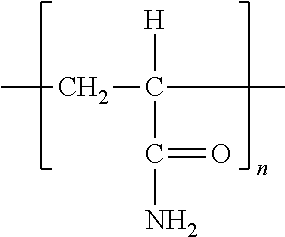
Poly(allylamine hydrochloride) PAH 
Polymethacrylic acid PMA 
Polystyrene sulfonate SPS 
poly(amidoamine) (note: G4 as used herein, but drawn as G1 for clarity) PAMAM 
poly(4-vinylpyridine) P4VP 
Polydiallyldimethyl- ammonium chloride PDAC 
Linear Poly(ethyleneimine) LPEI 
Poly(ethyleneoxide) PEO 
Poly(2-acrylamido-2- methyl-1-propane sulfonic acid) PAMPS 
Poly(vinylpyrrolidone) PVP 
Poly(vinylalcohol) PVA 
Poly(ethylene glycol) PEG 
Poly(aniline) PANI 
Poly(styrene sulfonic acid-maleic acid) PSSM3:1 
Poly(acryl-co- acrylamide acid) PAA-co-AAm 
Poly(dimethylamine- co-epichlorohydrin) PDME 
The foregoing list is intended to be exemplary and is not exhaustive. A person skilled in the art, given the disclosure and teachings herein, would be able to select a number of other useful charged polymeric materials, such as, for example, sulfonated polyanions of polysulfones or polyetherketones. - In certain embodiments, metal oxide nanoparticles may be used in the assembly layer-by-layer films. The term “metal” is also used herein to include metalloids belonging to groups 13-15 of the Periodic table. (For purposes of this invention, the chemical elements are identified in accordance with the Periodic Table of the Elements, CAS version, Handbook of Chemistry and Physics, 67th Ed., 1986-87, inside cover.) In other words, the metal in the metal oxide nanoparticles of the present invention may be Li, Na, K, Mg, Ca, Sr, Ba, Sc, Y, La, Ti, Zr, Hf, V, Nb, Ta, Cr, Mo, W, Mn, Tc, Re, Fe, Ru, Os, Co, Rh, Ir, Ni, Pd, Pt, Cu, Ag, Au, Zn, Cd, Hg, B, Al, Ga, In, Tl, Si, Ge, Sn, Pb, As, Sb, Bi or a lanthanide such as Ce. Examples of metal oxides include TiO2, Ta2O5, Nb2O5, ZrO2, Y2O3, Al2O3, and SiO2. The metal oxide may also be a mixed oxide containing two, three, four or five different metals.
- The term “nanoparticle” refers to particles which have an average diameter of between about 1 and about 500 nanometers. In certain embodiments, a nanoparticle may have an average diameter of between about 1 and about 100 nanometers.
- The invention now being generally described, it will be more readily understood by reference to the following, which is included merely for purposes of illustration of certain aspects and embodiments of the present invention, and is not intended to limit the invention.
- Nonwoven meshes of nylon fibers were made by electrospinning a solution of 10% nylon-6,6 (45,000 Mw) (Scientific Polymer Products) in hexafluoroisopropanol (Aldrich) at 0.1 mL/min with a needle-to-collector distance of 31 cm and a source voltage of 26.8 kV for 40 minutes using a parallel plate electrospinning apparatus. Mats were soaked in 0.02 M aqueous solution of PAH (56,000 Mw (Aldrich) for 30 minutes prior to LbL treatment.
- LPEI (25,000 Mw) (Polysciences), PAA (15,000 Mw, 35% aqueous solution) (Aldrich), PAMAM (G4, 22% solution in methanol) (Dendritech), SPS (1,000,000 Mw (Aldrich) and PDAC (150,000 Mw, 20% aqueous solution) (Aldrich) were used as received and prepared as 0.02 M solutions, based on the repeat unit molecular weight, in Milli-Q water. A colloidal solution of TiO2 nanoparticles was synthesized (as described in Krogman, K. C., Zacharia, N. S., Grillo, D. M., & Hammond, P. T., Photocatalytic layer-by-layer coatings for degradation of acutely toxic agents. Chem Mater 20 (5), 1924-1930 (2008)) and diluted to a concentration of 1.65 mg/mL.
- Conformal (TiO2/PDAC)n coatings were then deposited using a vacuum assisted Spray-LbL technique. See PCT Publication No. WO/2008/030474, which is hereby incorporated by reference in its entirety. Four inch diameter circles of electrospun Nylon were cut and mounted on coarse mesh stainless steel wire cloth (9×9 mesh) which had been previously fixed in the mouth of a large funnel. The other end of the funnel was connected via rubber tubing to an adjustable-flow single stage vacuum generator operating on compressed air, which was adjusted prior to operation to set the flow rate of air through the electrospun mat during spray deposition. The flow rate, and hence Re number, were determined using a high sensitivity anemometer. During operation the mat was held in place on the wire mesh only by vacuum. Atomized sprays of solutions were formed using modified air-brushes assembled into an automated system, and driven by compressed ultra-pure argon regulated to 20 psi. Cationic PDAC (150,000 Mw, 20% aqueous solution) (Aldrich) solution was first sprayed for 3 seconds at a rate of 0.2 mL/s at a sufficient distance and cone angle to reach the entire cross section of the mounted mat simultaneously. Two seconds later
pH 10 rinse water was sprayed from a similar distance for 10 seconds, and allowed 2 seconds for the bulk to be removed by vacuum. This half cycle was repeated for the anionic TiO2, and the total cycle (34 seconds) was repeated 25 times to develop the conformal coating. - Vacuum was removed and the mat flipped and remounted. No further drying time was necessary, and the still-damp mat was easily mounted on the same stainless steel screen. Bridged coatings were formed using LPEI (25,000 Mw) (Polysciences), PAA (15,000 Mw, 35% aqueous solution) (Aldrich), PAMAM (G4, 22% solution in methanol) (Dendritech), SPS (1,000,000 Mw) (Aldrich) and PDAC prepared as 0.02 M solutions, based on the repeat unit molecular weight, in Milli-Q water. While the same spray geometry was used, the time between sprays was increased from 2 seconds to 6 seconds. In the absence of vacuum solutions were observed to cascade down the mat surface, and therefore were allowed greater rest time (50 second cycle).
- Mats were coated with a 10 nm layer of Au/Pd and imaged using a JEOL JSM-6060 Scanning Electron Microscope. Average fiber diameter was determined by measuring 40 to 60 individual fibers on both sides of the electrospun mat. Surface area measurements were performed by BET (Micromeritics, ASAP 2020), and verified using both nitrogen and krypton as the adsorbent gas.
- Treated mats were mounted in a stainless steel permeation cell and subjected to a saturated vapor of CEES (Aldrich) evolving from a 3 μL, drop. Meanwhile a stream of ultrapure compressed air (AirGas) was passed at 50 SCCM beneath the sample and analyzed using a Total Hydrocarbon Analyzer (Gow-MAC Instruments, Series 23-550) equipped with a flame ionization detector. During UV testing the photocatalytic side of the material was also exposed to a UV spot source (Dymax, Blue Wave 200) filtered to 50 mW/cm2 intensity. Note, although CEES is a less toxic simulant for HD mustard gas extreme caution should still be exercised when working with it. Water vapor permeation tests were conducted using a Dynamic Moisture Permeation Cell by passing air at two different relative humidities over opposite sides of the treated mat, and measuring the change in water vapor in each stream.
- All U.S. patents and U.S. published patent applications cited herein are hereby incorporated by reference in their entireties.
- While several embodiments of the present invention have been described and illustrated herein, those of ordinary skill in the art will readily envision a variety of other means and/or structures for performing the functions and/or obtaining the results and/or one or more of the advantages described herein, and each of such variations and/or modifications is deemed to be within the scope of the present invention. More generally, those skilled in the art will readily appreciate that all parameters, dimensions, materials, and configurations described herein are meant to be exemplary and that the actual parameters, dimensions, materials, and/or configurations will depend upon the specific application or applications for which the teachings of the present invention is/are used. Those skilled in the art will recognize, or be able to ascertain using no more than routine experimentation, many equivalents to the specific embodiments of the invention described herein. It is, therefore, to be understood that the foregoing embodiments are presented by way of example only and that, within the scope of the appended claims and equivalents thereto, the invention may be practiced otherwise than as specifically described and claimed. The present invention is directed to each individual feature, system, article, material, kit, and/or method described herein. In addition, any combination of two or more such features, systems, articles, materials, kits, and/or methods, if such features, systems, articles, materials, kits, and/or methods are not mutually inconsistent, is included within the scope of the present invention.
Claims (24)
1. A multi-functional material, comprising a porous, fibrous substrate, wherein substantially all of the fibers of the substrate are conformally coated with a first layer-by-layer film, and substantially all of the pores in the substrate are at least partially filed with a second layer-by-layer film.
2. The material of claim 1 , wherein the substrate comprises electrospun fibers.
3. The material of claim 1 , wherein the first layer-by-layer film comprises a cationic polyelectrolyte.
4. The material of claim 3 , wherein the cationic polyelectrolyte is PDAC.
5. The material of claim 1 , wherein the first layer-by-layer film comprises an anionic metal oxide nanoparticle.
6. The material of claim 5 , wherein the anionic metal oxide nanoparticle is TiO2.
7. The material of claim 1 , wherein the first layer-by-layer film comprises between 1 and about 200 bilayers.
8. The material of claim 1 , wherein the first layer-by-layer film is (PDAC/TiO2)25.
9. The material of claim 1 , wherein the second layer-by-layer film comprises a cationic polyelectrolyte.
10. The material of claim 9 , wherein the cationic polyelectrolyte is PDAC, PAMAM (G4), PAH or LPEI.
11. The material of claim 1 , wherein the second layer-by-layer film comprises an anionic polyelectrolyte.
12. The material of claim 11 , wherein the anionic polyelectrolyte is SPS or PAA.
13. The material of claim 1 , wherein the second layer-by-layer film comprises between 1 and about 200 bilayers.
14. The material of claim 1 , wherein the second layer-by-layer film is (PDAC/SPS)50, (PAMAM/PAA)50, (PAH/PAA)100 or (LPEI/PAA)100.
15. The material of claim 1 , wherein said material is a selectively-reactive gas purification membrane, a self-cleaning fabric, a material used for water purification, or a protein functionalization scaffold used for tissue engineering.
16. A method of fabricating a multi-functional material from a porous, fibrous substrate comprising the steps of:
alternatingly depositing a first material and a second material on a porous, fibrous substrate, thereby conformally coating the fibers of the substrate with a first layer-by-layer film; and
alternatingly depositing a third material and a fourth material on the conformally coated substrate, thereby at least partially filling the pores in the substrate with a second layer-by-layer film.
17. The method of claim 16 , wherein the substrate comprises electrospun fibers.
18. The method of claim 16 , wherein the first layer-by-layer film is deposited by a spray assisted layer-by-layer process.
19. The method of claim 18 , wherein the spray assisted layer-by-layer process comprises the steps of spraying a first material from a first distance, at a first rate, for a first time, onto the substrate; and spraying a second material from a second distance, at a second rate, for a second time, onto the substrate.
20. The method of claim 19 , wherein the spray assisted layer-by-layer process further comprises the step of imposing a pressure gradient across the substrate while the fibers in the substrate are conformally coated with the first layer-by-layer film.
21. The method of claim 16 , wherein the second layer-by-layer film is deposited by a spray assisted layer-by-layer process.
22. The method of claim 21 , wherein the spray assisted layer-by-layer process comprises the steps of spraying a third material from a third distance, at a third rate, for a third time, onto the conformally coated substrate; and spraying a fourth material from a fourth distance, at a fourth rate, for a fourth time, onto the conformally coated substrate.
23. The method of claim 16 wherein the substrate has a first side and a second side; the first layer-by-layer film is deposited by a spray assisted layer-by-layer process applied to the first side of the substrate; and the second layer-by-layer film is deposited by a spray assembly layer-by-layer process applied to the second side of the substrate.
24. The method of claim 16 , wherein said material is a selectively-reactive gas purification membrane, a self-cleaning fabric, a material used for water purification, or a protein functionalization scaffold used for tissue engineering.
Priority Applications (1)
| Application Number | Priority Date | Filing Date | Title |
|---|---|---|---|
| US12/561,757 US20110064936A1 (en) | 2009-09-17 | 2009-09-17 | Method of Asymmetrically Functionalizing Porous Materials |
Applications Claiming Priority (1)
| Application Number | Priority Date | Filing Date | Title |
|---|---|---|---|
| US12/561,757 US20110064936A1 (en) | 2009-09-17 | 2009-09-17 | Method of Asymmetrically Functionalizing Porous Materials |
Publications (1)
| Publication Number | Publication Date |
|---|---|
| US20110064936A1 true US20110064936A1 (en) | 2011-03-17 |
Family
ID=43730864
Family Applications (1)
| Application Number | Title | Priority Date | Filing Date |
|---|---|---|---|
| US12/561,757 Abandoned US20110064936A1 (en) | 2009-09-17 | 2009-09-17 | Method of Asymmetrically Functionalizing Porous Materials |
Country Status (1)
| Country | Link |
|---|---|
| US (1) | US20110064936A1 (en) |
Cited By (31)
| Publication number | Priority date | Publication date | Assignee | Title |
|---|---|---|---|---|
| CN102284253A (en) * | 2011-06-13 | 2011-12-21 | 北京工业大学 | Method for assembling organic/inorganic hollow fiber composite membrane |
| CN102285183A (en) * | 2011-04-28 | 2011-12-21 | 吉林大学 | Polymer double-layer self-supporting film and application in preparation of actuator |
| US20120171573A1 (en) * | 2010-12-29 | 2012-07-05 | Industrial Technology Research Institute | Hybrid materials using ionic particles |
| CN102660202A (en) * | 2012-05-14 | 2012-09-12 | 吉林大学 | Method for preparing adhesive coating and adhesive film based on layer-by-layer assembly technology |
| WO2012163854A1 (en) * | 2011-05-27 | 2012-12-06 | Karlsruher Institut für Technologie | Device and method for producing highly porous, crystalline surface coatings |
| WO2014004479A2 (en) * | 2012-06-25 | 2014-01-03 | Massachusetts Institute Of Technology | Porous film |
| WO2014099367A1 (en) | 2012-12-20 | 2014-06-26 | 3M Innovative Properties Company | Method of making multilayer optical film comprising layer-by-layer self-assembled layers and articles |
| WO2014159521A1 (en) * | 2013-03-14 | 2014-10-02 | University Of Delaware | Gold nanorod/polymer nanocomposites and sensors based thereon |
| WO2014193550A1 (en) | 2013-05-31 | 2014-12-04 | 3M Innovative Properties Company | Methods of layer by layer self-assembly of a polyelectrolyte comprising light absorbing or stabilizing compound and articles |
| WO2015095317A1 (en) | 2013-12-19 | 2015-06-25 | 3M Innovative Properties Company | Articles comprising self-assembled layers comprising nanoparticles with a phosphorous surface treatment |
| US20150343389A1 (en) * | 2012-06-26 | 2015-12-03 | Fujifilm Manufacturing Europe Bv | Curable Compositions and Membranes |
| CN105169959A (en) * | 2015-07-20 | 2015-12-23 | 北京工业大学 | Method for rapid and environmentally-friendly production of compact separation membrane |
| US20170113179A1 (en) * | 2015-10-22 | 2017-04-27 | King Fahd University Of Petroleum And Minerals | Si-y nanocomposite membrane and methods of making and use thereof |
| US20170179436A1 (en) * | 2015-08-03 | 2017-06-22 | Shenzhen China Star Optoelectronics Technology Co., Ltd. | Manufacturing method for organic electroluminescent device and organic electroluminescent device |
| CN106984363A (en) * | 2017-05-17 | 2017-07-28 | 中国地质大学(北京) | A kind of method that utilization LBL self-assembly prepares catalysis material |
| CN107190499A (en) * | 2017-05-12 | 2017-09-22 | 平湖市新保纺织科技有限公司 | A kind of compound fabric of self-cleaning antibacterial uvioresistant and preparation method thereof |
| WO2018005088A1 (en) | 2016-06-27 | 2018-01-04 | 3M Innovative Properties Company | Compositions comprising nanoparticles functionalized with an alpha-hydroxy acid or salt, articles, and methods |
| CN108456401A (en) * | 2018-05-02 | 2018-08-28 | 北京中环鑫汇科技有限公司 | A kind of pipe composite and preparation method thereof |
| WO2020125377A1 (en) * | 2018-12-17 | 2020-06-25 | 太原理工大学 | Patterned layer-by-layer assembled self-supporting film-based flexible transparent conductive film and preparation method therefor |
| US10734454B2 (en) | 2016-09-02 | 2020-08-04 | 3M Innovative Properties Company | Display stack including emissive display and color correction film |
| WO2020250180A1 (en) | 2019-06-12 | 2020-12-17 | 3M Innovative Properties Company | High transmission light control films with asymmetric light output |
| WO2020250090A1 (en) | 2019-06-12 | 2020-12-17 | 3M Innovative Properties Company | Coated substrate comprising electrically conductive particles and dried aqueous dispersion of organic polymer |
| US11235290B2 (en) | 2017-02-17 | 2022-02-01 | The Research Foundation For The State University Of New York | High-flux thin-film nanocomposite reverse osmosis membrane for desalination |
| CN114588788A (en) * | 2022-01-28 | 2022-06-07 | 河北科技大学 | Composite fiber membrane and preparation method and application thereof |
| WO2022238781A1 (en) | 2021-05-10 | 2022-11-17 | 3M Innovative Properties Company | Optical system including light control film and fresnel lens |
| US11550183B2 (en) | 2018-08-01 | 2023-01-10 | 3M Innovative Properties Company | High transmission light control film |
| WO2023047204A1 (en) | 2021-09-24 | 2023-03-30 | 3M Innovative Properties Company | Coated microstructured films, methods of making same, and methods of making light control films |
| WO2023119007A1 (en) | 2021-12-22 | 2023-06-29 | 3M Innovative Properties Company | Articles having a coating including polyelectrolytes and a photocleavable polymer, and methods of making same |
| US11885989B2 (en) | 2017-12-13 | 2024-01-30 | 3M Innovative Properties Company | High transmission light control film |
| US11906252B2 (en) | 2019-05-31 | 2024-02-20 | 3M Innovative Properties Company | Composite cooling film and article including the same |
| US11947135B2 (en) | 2017-12-13 | 2024-04-02 | 3M Innovative Properties Company | High transmission light control film |
Citations (8)
| Publication number | Priority date | Publication date | Assignee | Title |
|---|---|---|---|---|
| US20020190434A1 (en) * | 1999-10-08 | 2002-12-19 | 3M Innovative Properties Company | Method and apparatus for making a fibrous electret web using a wetting liquid and an aqueous polar liquid |
| US20030124332A1 (en) * | 2001-08-28 | 2003-07-03 | Guoqiang Mao | Multi-layer coated porous materials and methods of making the same |
| US20040047979A1 (en) * | 2002-09-11 | 2004-03-11 | Yongxing Qiu | Method for applying an LbL coating onto a medical device |
| US6811805B2 (en) * | 2001-05-30 | 2004-11-02 | Novatis Ag | Method for applying a coating |
| US20060094320A1 (en) * | 2004-11-02 | 2006-05-04 | Kimberly-Clark Worldwide, Inc. | Gradient nanofiber materials and methods for making same |
| US20060263417A1 (en) * | 2005-05-10 | 2006-11-23 | Lelkes Peter I | Electrospun blends of natural and synthetic polymer fibers as tissue engineering scaffolds |
| US20090088679A1 (en) * | 2005-02-07 | 2009-04-02 | Massachusetts Institute Of Technology | Electronically-Degradable Layer-by-Layer Thin Films |
| US20100159366A1 (en) * | 2008-08-15 | 2010-06-24 | Massachusetts Institute Of Technology | Layer-by-layer assemblies of carbon-based nanostructures and their applications in energy storage and generation devices |
-
2009
- 2009-09-17 US US12/561,757 patent/US20110064936A1/en not_active Abandoned
Patent Citations (8)
| Publication number | Priority date | Publication date | Assignee | Title |
|---|---|---|---|---|
| US20020190434A1 (en) * | 1999-10-08 | 2002-12-19 | 3M Innovative Properties Company | Method and apparatus for making a fibrous electret web using a wetting liquid and an aqueous polar liquid |
| US6811805B2 (en) * | 2001-05-30 | 2004-11-02 | Novatis Ag | Method for applying a coating |
| US20030124332A1 (en) * | 2001-08-28 | 2003-07-03 | Guoqiang Mao | Multi-layer coated porous materials and methods of making the same |
| US20040047979A1 (en) * | 2002-09-11 | 2004-03-11 | Yongxing Qiu | Method for applying an LbL coating onto a medical device |
| US20060094320A1 (en) * | 2004-11-02 | 2006-05-04 | Kimberly-Clark Worldwide, Inc. | Gradient nanofiber materials and methods for making same |
| US20090088679A1 (en) * | 2005-02-07 | 2009-04-02 | Massachusetts Institute Of Technology | Electronically-Degradable Layer-by-Layer Thin Films |
| US20060263417A1 (en) * | 2005-05-10 | 2006-11-23 | Lelkes Peter I | Electrospun blends of natural and synthetic polymer fibers as tissue engineering scaffolds |
| US20100159366A1 (en) * | 2008-08-15 | 2010-06-24 | Massachusetts Institute Of Technology | Layer-by-layer assemblies of carbon-based nanostructures and their applications in energy storage and generation devices |
Cited By (44)
| Publication number | Priority date | Publication date | Assignee | Title |
|---|---|---|---|---|
| US9136516B2 (en) * | 2010-12-29 | 2015-09-15 | Industrial Technology Research Institute | Hybrid materials using ionic particles |
| US20120171573A1 (en) * | 2010-12-29 | 2012-07-05 | Industrial Technology Research Institute | Hybrid materials using ionic particles |
| CN102285183A (en) * | 2011-04-28 | 2011-12-21 | 吉林大学 | Polymer double-layer self-supporting film and application in preparation of actuator |
| WO2012163854A1 (en) * | 2011-05-27 | 2012-12-06 | Karlsruher Institut für Technologie | Device and method for producing highly porous, crystalline surface coatings |
| US20140302304A1 (en) * | 2011-05-27 | 2014-10-09 | Karlsruher Institut Fuer Technologie | Device and method for producing highly porous, crystalline surface coatings |
| US9757767B2 (en) * | 2011-05-27 | 2017-09-12 | Karlsruher Institut Fuer Technologie | Device and method for producing highly porous, crystalline surface coatings |
| CN102284253A (en) * | 2011-06-13 | 2011-12-21 | 北京工业大学 | Method for assembling organic/inorganic hollow fiber composite membrane |
| CN102660202A (en) * | 2012-05-14 | 2012-09-12 | 吉林大学 | Method for preparing adhesive coating and adhesive film based on layer-by-layer assembly technology |
| WO2014004479A2 (en) * | 2012-06-25 | 2014-01-03 | Massachusetts Institute Of Technology | Porous film |
| WO2014004479A3 (en) * | 2012-06-25 | 2014-05-30 | Massachusetts Institute Of Technology | Porous film |
| US9700848B2 (en) * | 2012-06-26 | 2017-07-11 | Fujifilm Manufacturing Europe B.V. | Curable compositions and membranes |
| US20150343389A1 (en) * | 2012-06-26 | 2015-12-03 | Fujifilm Manufacturing Europe Bv | Curable Compositions and Membranes |
| WO2014099367A1 (en) | 2012-12-20 | 2014-06-26 | 3M Innovative Properties Company | Method of making multilayer optical film comprising layer-by-layer self-assembled layers and articles |
| US9829604B2 (en) | 2012-12-20 | 2017-11-28 | 3M Innovative Properties Company | Method of making multilayer optical film comprising layer-by-layer self-assembled layers and articles |
| WO2014159521A1 (en) * | 2013-03-14 | 2014-10-02 | University Of Delaware | Gold nanorod/polymer nanocomposites and sensors based thereon |
| US9897547B2 (en) | 2013-03-14 | 2018-02-20 | University Of Delaware | Gold nanorod/polymer nanocomposites and sensors based thereon |
| WO2014193550A1 (en) | 2013-05-31 | 2014-12-04 | 3M Innovative Properties Company | Methods of layer by layer self-assembly of a polyelectrolyte comprising light absorbing or stabilizing compound and articles |
| US9902869B2 (en) | 2013-05-31 | 2018-02-27 | 3M Innovative Properties Company | Methods of layer by layer self-assembly of polyelectrolyte comprising light absorbing or stabilizing compound and articles |
| US10365415B2 (en) | 2013-12-19 | 2019-07-30 | 3M Innovative Properties Company | Articles comprising self-assembled layers comprising nanoparticles with a phosphorous surface treatment |
| WO2015095317A1 (en) | 2013-12-19 | 2015-06-25 | 3M Innovative Properties Company | Articles comprising self-assembled layers comprising nanoparticles with a phosphorous surface treatment |
| CN105169959A (en) * | 2015-07-20 | 2015-12-23 | 北京工业大学 | Method for rapid and environmentally-friendly production of compact separation membrane |
| US9698381B1 (en) * | 2015-08-03 | 2017-07-04 | Shenzhen China Star Optoelectronics Technology Co., Ltd. | Manufacturing method for organic electroluminescent device and organic electroluminescent device |
| US20170179436A1 (en) * | 2015-08-03 | 2017-06-22 | Shenzhen China Star Optoelectronics Technology Co., Ltd. | Manufacturing method for organic electroluminescent device and organic electroluminescent device |
| US9770688B2 (en) * | 2015-10-22 | 2017-09-26 | King Fahd University Of Petroleum And Minerals | Si—Y nanocomposite membrane and methods of making and use thereof |
| US20170113179A1 (en) * | 2015-10-22 | 2017-04-27 | King Fahd University Of Petroleum And Minerals | Si-y nanocomposite membrane and methods of making and use thereof |
| US9815019B1 (en) | 2015-10-22 | 2017-11-14 | King Fahd University Of Petroleum And Minerals | Gas separation device with nanocomposite membrane |
| WO2018005088A1 (en) | 2016-06-27 | 2018-01-04 | 3M Innovative Properties Company | Compositions comprising nanoparticles functionalized with an alpha-hydroxy acid or salt, articles, and methods |
| US10734454B2 (en) | 2016-09-02 | 2020-08-04 | 3M Innovative Properties Company | Display stack including emissive display and color correction film |
| US11235290B2 (en) | 2017-02-17 | 2022-02-01 | The Research Foundation For The State University Of New York | High-flux thin-film nanocomposite reverse osmosis membrane for desalination |
| CN107190499A (en) * | 2017-05-12 | 2017-09-22 | 平湖市新保纺织科技有限公司 | A kind of compound fabric of self-cleaning antibacterial uvioresistant and preparation method thereof |
| CN106984363A (en) * | 2017-05-17 | 2017-07-28 | 中国地质大学(北京) | A kind of method that utilization LBL self-assembly prepares catalysis material |
| US11947135B2 (en) | 2017-12-13 | 2024-04-02 | 3M Innovative Properties Company | High transmission light control film |
| US11885989B2 (en) | 2017-12-13 | 2024-01-30 | 3M Innovative Properties Company | High transmission light control film |
| CN108456401A (en) * | 2018-05-02 | 2018-08-28 | 北京中环鑫汇科技有限公司 | A kind of pipe composite and preparation method thereof |
| US11550183B2 (en) | 2018-08-01 | 2023-01-10 | 3M Innovative Properties Company | High transmission light control film |
| US11940689B2 (en) | 2018-08-01 | 2024-03-26 | 3M Innovative Properties Company | High transmission light control film |
| WO2020125377A1 (en) * | 2018-12-17 | 2020-06-25 | 太原理工大学 | Patterned layer-by-layer assembled self-supporting film-based flexible transparent conductive film and preparation method therefor |
| US11906252B2 (en) | 2019-05-31 | 2024-02-20 | 3M Innovative Properties Company | Composite cooling film and article including the same |
| WO2020250180A1 (en) | 2019-06-12 | 2020-12-17 | 3M Innovative Properties Company | High transmission light control films with asymmetric light output |
| WO2020250090A1 (en) | 2019-06-12 | 2020-12-17 | 3M Innovative Properties Company | Coated substrate comprising electrically conductive particles and dried aqueous dispersion of organic polymer |
| WO2022238781A1 (en) | 2021-05-10 | 2022-11-17 | 3M Innovative Properties Company | Optical system including light control film and fresnel lens |
| WO2023047204A1 (en) | 2021-09-24 | 2023-03-30 | 3M Innovative Properties Company | Coated microstructured films, methods of making same, and methods of making light control films |
| WO2023119007A1 (en) | 2021-12-22 | 2023-06-29 | 3M Innovative Properties Company | Articles having a coating including polyelectrolytes and a photocleavable polymer, and methods of making same |
| CN114588788A (en) * | 2022-01-28 | 2022-06-07 | 河北科技大学 | Composite fiber membrane and preparation method and application thereof |
Similar Documents
| Publication | Publication Date | Title |
|---|---|---|
| US20110064936A1 (en) | Method of Asymmetrically Functionalizing Porous Materials | |
| Mailley et al. | A review on the impact of humidity during electrospinning: From the nanofiber structure engineering to the applications | |
| Krogman et al. | Spraying asymmetry into functional membranes layer-by-layer | |
| US11724234B2 (en) | Multilayer thin film nanocomposite membranes prepared by molecular layer-by-layer assembly | |
| Shan et al. | Microphase diffusion-controlled interfacial polymerization for an ultrahigh permeability nanofiltration membrane | |
| US20110192789A1 (en) | Metal or metal oxide deposited fibrous materials | |
| Moradi et al. | Fabrication of high flux and antifouling mixed matrix fumarate-alumoxane/PAN membranes via electrospinning for application in membrane bioreactors | |
| US8231013B2 (en) | Articles comprising a fibrous support | |
| US20180071693A1 (en) | Filtration membranes, and related nano and/or micro fibers, composites, methods and systems | |
| US20190046934A1 (en) | Filtration membranes and related compositions, methods and systems | |
| Yoon et al. | Formation of functional polyethersulfone electrospun membrane for water purification by mixed solvent and oxidation processes | |
| US20130105395A1 (en) | Nanostructured membranes for engineered osmosis applications | |
| Ahmad et al. | Accelerated spraying-assisted layer by layer assembly of polyethyleneimine/titania nanosheet on thin film composite membrane for reverse osmosis desalination | |
| WO2009025900A2 (en) | High flux fluid separation membranes comprising a cellulose or cellulose derivative layer | |
| Ray et al. | Electrospinning: A versatile fabrication technique for nanofibrous membranes for use in desalination | |
| WO2007001405A9 (en) | High flux and low fouling filtration media | |
| Shi et al. | Selective swelling of electrospun block copolymers: from perforated nanofibers to high flux and responsive ultrafiltration membranes | |
| DE102009003374A1 (en) | Permanent hydrophilic porous coatings on a substrate and porous membranes thereof | |
| US20160137802A1 (en) | Multiscale porous polymer films | |
| Ritcharoen et al. | Development of polyelectrolyte multilayer-coated electrospun cellulose acetate fiber mat as composite membranes | |
| US20160369076A1 (en) | Super hydrophobic multiscale porous polymer films | |
| Tabe | A review of electrospun nanofber membranes | |
| Moon et al. | A highly efficient nanofibrous air filter membrane fabricated using electrospun amphiphilic PVDF-g-POEM double comb copolymer | |
| Khulbe et al. | The advances of electrospun nanofibers in membrane technology | |
| US20140202953A1 (en) | Multilayer Membrane Containing Carbon Nanotube Manufactured by Layer-By-Layer Assembly Method |
Legal Events
| Date | Code | Title | Description |
|---|---|---|---|
| AS | Assignment |
Owner name: MASSACHUSETTS INSTITUTE OF TECHNOLOGY, MASSACHUSET Free format text: ASSIGNMENT OF ASSIGNORS INTEREST;ASSIGNORS:HAMMOND-CUNNINGHAM, PAULA T.;KROGMAN, KEVIN C.;LOWERY, JOSEPH L.;AND OTHERS;SIGNING DATES FROM 20090925 TO 20091010;REEL/FRAME:023676/0119 |
|
| STCB | Information on status: application discontinuation |
Free format text: ABANDONED -- FAILURE TO RESPOND TO AN OFFICE ACTION |