US20100318178A1 - Method and apparatus for allowing blood flow through an occluded vessel - Google Patents
Method and apparatus for allowing blood flow through an occluded vessel Download PDFInfo
- Publication number
- US20100318178A1 US20100318178A1 US12/815,428 US81542810A US2010318178A1 US 20100318178 A1 US20100318178 A1 US 20100318178A1 US 81542810 A US81542810 A US 81542810A US 2010318178 A1 US2010318178 A1 US 2010318178A1
- Authority
- US
- United States
- Prior art keywords
- occlusion
- tubular body
- diameter state
- expanding device
- large diameter
- Prior art date
- Legal status (The legal status is an assumption and is not a legal conclusion. Google has not performed a legal analysis and makes no representation as to the accuracy of the status listed.)
- Granted
Links
Images


Classifications
-
- A—HUMAN NECESSITIES
- A61—MEDICAL OR VETERINARY SCIENCE; HYGIENE
- A61F—FILTERS IMPLANTABLE INTO BLOOD VESSELS; PROSTHESES; DEVICES PROVIDING PATENCY TO, OR PREVENTING COLLAPSING OF, TUBULAR STRUCTURES OF THE BODY, e.g. STENTS; ORTHOPAEDIC, NURSING OR CONTRACEPTIVE DEVICES; FOMENTATION; TREATMENT OR PROTECTION OF EYES OR EARS; BANDAGES, DRESSINGS OR ABSORBENT PADS; FIRST-AID KITS
- A61F2/00—Filters implantable into blood vessels; Prostheses, i.e. artificial substitutes or replacements for parts of the body; Appliances for connecting them with the body; Devices providing patency to, or preventing collapsing of, tubular structures of the body, e.g. stents
- A61F2/01—Filters implantable into blood vessels
-
- A—HUMAN NECESSITIES
- A61—MEDICAL OR VETERINARY SCIENCE; HYGIENE
- A61F—FILTERS IMPLANTABLE INTO BLOOD VESSELS; PROSTHESES; DEVICES PROVIDING PATENCY TO, OR PREVENTING COLLAPSING OF, TUBULAR STRUCTURES OF THE BODY, e.g. STENTS; ORTHOPAEDIC, NURSING OR CONTRACEPTIVE DEVICES; FOMENTATION; TREATMENT OR PROTECTION OF EYES OR EARS; BANDAGES, DRESSINGS OR ABSORBENT PADS; FIRST-AID KITS
- A61F2/00—Filters implantable into blood vessels; Prostheses, i.e. artificial substitutes or replacements for parts of the body; Appliances for connecting them with the body; Devices providing patency to, or preventing collapsing of, tubular structures of the body, e.g. stents
- A61F2/82—Devices providing patency to, or preventing collapsing of, tubular structures of the body, e.g. stents
- A61F2/844—Devices providing patency to, or preventing collapsing of, tubular structures of the body, e.g. stents folded prior to deployment
-
- A—HUMAN NECESSITIES
- A61—MEDICAL OR VETERINARY SCIENCE; HYGIENE
- A61B—DIAGNOSIS; SURGERY; IDENTIFICATION
- A61B17/00—Surgical instruments, devices or methods, e.g. tourniquets
- A61B17/22—Implements for squeezing-off ulcers or the like on the inside of inner organs of the body; Implements for scraping-out cavities of body organs, e.g. bones; Calculus removers; Calculus smashing apparatus; Apparatus for removing obstructions in blood vessels, not otherwise provided for
- A61B17/221—Gripping devices in the form of loops or baskets for gripping calculi or similar types of obstructions
-
- A—HUMAN NECESSITIES
- A61—MEDICAL OR VETERINARY SCIENCE; HYGIENE
- A61B—DIAGNOSIS; SURGERY; IDENTIFICATION
- A61B17/00—Surgical instruments, devices or methods, e.g. tourniquets
- A61B17/32—Surgical cutting instruments
- A61B17/3205—Excision instruments
- A61B17/3207—Atherectomy devices working by cutting or abrading; Similar devices specially adapted for non-vascular obstructions
- A61B17/320725—Atherectomy devices working by cutting or abrading; Similar devices specially adapted for non-vascular obstructions with radially expandable cutting or abrading elements
-
- A—HUMAN NECESSITIES
- A61—MEDICAL OR VETERINARY SCIENCE; HYGIENE
- A61B—DIAGNOSIS; SURGERY; IDENTIFICATION
- A61B90/00—Instruments, implements or accessories specially adapted for surgery or diagnosis and not covered by any of the groups A61B1/00 - A61B50/00, e.g. for luxation treatment or for protecting wound edges
- A61B90/39—Markers, e.g. radio-opaque or breast lesions markers
-
- A—HUMAN NECESSITIES
- A61—MEDICAL OR VETERINARY SCIENCE; HYGIENE
- A61F—FILTERS IMPLANTABLE INTO BLOOD VESSELS; PROSTHESES; DEVICES PROVIDING PATENCY TO, OR PREVENTING COLLAPSING OF, TUBULAR STRUCTURES OF THE BODY, e.g. STENTS; ORTHOPAEDIC, NURSING OR CONTRACEPTIVE DEVICES; FOMENTATION; TREATMENT OR PROTECTION OF EYES OR EARS; BANDAGES, DRESSINGS OR ABSORBENT PADS; FIRST-AID KITS
- A61F2/00—Filters implantable into blood vessels; Prostheses, i.e. artificial substitutes or replacements for parts of the body; Appliances for connecting them with the body; Devices providing patency to, or preventing collapsing of, tubular structures of the body, e.g. stents
- A61F2/82—Devices providing patency to, or preventing collapsing of, tubular structures of the body, e.g. stents
- A61F2/86—Stents in a form characterised by the wire-like elements; Stents in the form characterised by a net-like or mesh-like structure
-
- A—HUMAN NECESSITIES
- A61—MEDICAL OR VETERINARY SCIENCE; HYGIENE
- A61M—DEVICES FOR INTRODUCING MEDIA INTO, OR ONTO, THE BODY; DEVICES FOR TRANSDUCING BODY MEDIA OR FOR TAKING MEDIA FROM THE BODY; DEVICES FOR PRODUCING OR ENDING SLEEP OR STUPOR
- A61M29/00—Dilators with or without means for introducing media, e.g. remedies
- A61M29/02—Dilators made of swellable material
-
- A—HUMAN NECESSITIES
- A61—MEDICAL OR VETERINARY SCIENCE; HYGIENE
- A61B—DIAGNOSIS; SURGERY; IDENTIFICATION
- A61B17/00—Surgical instruments, devices or methods, e.g. tourniquets
- A61B2017/00831—Material properties
- A61B2017/00893—Material properties pharmaceutically effective
-
- A—HUMAN NECESSITIES
- A61—MEDICAL OR VETERINARY SCIENCE; HYGIENE
- A61B—DIAGNOSIS; SURGERY; IDENTIFICATION
- A61B17/00—Surgical instruments, devices or methods, e.g. tourniquets
- A61B17/22—Implements for squeezing-off ulcers or the like on the inside of inner organs of the body; Implements for scraping-out cavities of body organs, e.g. bones; Calculus removers; Calculus smashing apparatus; Apparatus for removing obstructions in blood vessels, not otherwise provided for
- A61B17/22031—Gripping instruments, e.g. forceps, for removing or smashing calculi
- A61B2017/22034—Gripping instruments, e.g. forceps, for removing or smashing calculi for gripping the obstruction or the tissue part from inside
-
- A—HUMAN NECESSITIES
- A61—MEDICAL OR VETERINARY SCIENCE; HYGIENE
- A61B—DIAGNOSIS; SURGERY; IDENTIFICATION
- A61B17/00—Surgical instruments, devices or methods, e.g. tourniquets
- A61B17/22—Implements for squeezing-off ulcers or the like on the inside of inner organs of the body; Implements for scraping-out cavities of body organs, e.g. bones; Calculus removers; Calculus smashing apparatus; Apparatus for removing obstructions in blood vessels, not otherwise provided for
- A61B17/221—Gripping devices in the form of loops or baskets for gripping calculi or similar types of obstructions
- A61B2017/2215—Gripping devices in the form of loops or baskets for gripping calculi or similar types of obstructions having an open distal end
-
- A—HUMAN NECESSITIES
- A61—MEDICAL OR VETERINARY SCIENCE; HYGIENE
- A61F—FILTERS IMPLANTABLE INTO BLOOD VESSELS; PROSTHESES; DEVICES PROVIDING PATENCY TO, OR PREVENTING COLLAPSING OF, TUBULAR STRUCTURES OF THE BODY, e.g. STENTS; ORTHOPAEDIC, NURSING OR CONTRACEPTIVE DEVICES; FOMENTATION; TREATMENT OR PROTECTION OF EYES OR EARS; BANDAGES, DRESSINGS OR ABSORBENT PADS; FIRST-AID KITS
- A61F2/00—Filters implantable into blood vessels; Prostheses, i.e. artificial substitutes or replacements for parts of the body; Appliances for connecting them with the body; Devices providing patency to, or preventing collapsing of, tubular structures of the body, e.g. stents
- A61F2/82—Devices providing patency to, or preventing collapsing of, tubular structures of the body, e.g. stents
- A61F2/86—Stents in a form characterised by the wire-like elements; Stents in the form characterised by a net-like or mesh-like structure
- A61F2/88—Stents in a form characterised by the wire-like elements; Stents in the form characterised by a net-like or mesh-like structure the wire-like elements formed as helical or spiral coils
-
- A—HUMAN NECESSITIES
- A61—MEDICAL OR VETERINARY SCIENCE; HYGIENE
- A61F—FILTERS IMPLANTABLE INTO BLOOD VESSELS; PROSTHESES; DEVICES PROVIDING PATENCY TO, OR PREVENTING COLLAPSING OF, TUBULAR STRUCTURES OF THE BODY, e.g. STENTS; ORTHOPAEDIC, NURSING OR CONTRACEPTIVE DEVICES; FOMENTATION; TREATMENT OR PROTECTION OF EYES OR EARS; BANDAGES, DRESSINGS OR ABSORBENT PADS; FIRST-AID KITS
- A61F2220/00—Fixations or connections for prostheses classified in groups A61F2/00 - A61F2/26 or A61F2/82 or A61F9/00 or A61F11/00 or subgroups thereof
- A61F2220/0025—Connections or couplings between prosthetic parts, e.g. between modular parts; Connecting elements
- A61F2220/005—Connections or couplings between prosthetic parts, e.g. between modular parts; Connecting elements using adhesives
-
- A—HUMAN NECESSITIES
- A61—MEDICAL OR VETERINARY SCIENCE; HYGIENE
- A61F—FILTERS IMPLANTABLE INTO BLOOD VESSELS; PROSTHESES; DEVICES PROVIDING PATENCY TO, OR PREVENTING COLLAPSING OF, TUBULAR STRUCTURES OF THE BODY, e.g. STENTS; ORTHOPAEDIC, NURSING OR CONTRACEPTIVE DEVICES; FOMENTATION; TREATMENT OR PROTECTION OF EYES OR EARS; BANDAGES, DRESSINGS OR ABSORBENT PADS; FIRST-AID KITS
- A61F2220/00—Fixations or connections for prostheses classified in groups A61F2/00 - A61F2/26 or A61F2/82 or A61F9/00 or A61F11/00 or subgroups thereof
- A61F2220/0025—Connections or couplings between prosthetic parts, e.g. between modular parts; Connecting elements
- A61F2220/0058—Connections or couplings between prosthetic parts, e.g. between modular parts; Connecting elements soldered or brazed or welded
-
- A—HUMAN NECESSITIES
- A61—MEDICAL OR VETERINARY SCIENCE; HYGIENE
- A61F—FILTERS IMPLANTABLE INTO BLOOD VESSELS; PROSTHESES; DEVICES PROVIDING PATENCY TO, OR PREVENTING COLLAPSING OF, TUBULAR STRUCTURES OF THE BODY, e.g. STENTS; ORTHOPAEDIC, NURSING OR CONTRACEPTIVE DEVICES; FOMENTATION; TREATMENT OR PROTECTION OF EYES OR EARS; BANDAGES, DRESSINGS OR ABSORBENT PADS; FIRST-AID KITS
- A61F2220/00—Fixations or connections for prostheses classified in groups A61F2/00 - A61F2/26 or A61F2/82 or A61F9/00 or A61F11/00 or subgroups thereof
- A61F2220/0025—Connections or couplings between prosthetic parts, e.g. between modular parts; Connecting elements
- A61F2220/0075—Connections or couplings between prosthetic parts, e.g. between modular parts; Connecting elements sutured, ligatured or stitched, retained or tied with a rope, string, thread, wire or cable
-
- A—HUMAN NECESSITIES
- A61—MEDICAL OR VETERINARY SCIENCE; HYGIENE
- A61F—FILTERS IMPLANTABLE INTO BLOOD VESSELS; PROSTHESES; DEVICES PROVIDING PATENCY TO, OR PREVENTING COLLAPSING OF, TUBULAR STRUCTURES OF THE BODY, e.g. STENTS; ORTHOPAEDIC, NURSING OR CONTRACEPTIVE DEVICES; FOMENTATION; TREATMENT OR PROTECTION OF EYES OR EARS; BANDAGES, DRESSINGS OR ABSORBENT PADS; FIRST-AID KITS
- A61F2230/00—Geometry of prostheses classified in groups A61F2/00 - A61F2/26 or A61F2/82 or A61F9/00 or A61F11/00 or subgroups thereof
- A61F2230/0063—Three-dimensional shapes
- A61F2230/0073—Quadric-shaped
- A61F2230/0078—Quadric-shaped hyperboloidal
-
- A—HUMAN NECESSITIES
- A61—MEDICAL OR VETERINARY SCIENCE; HYGIENE
- A61F—FILTERS IMPLANTABLE INTO BLOOD VESSELS; PROSTHESES; DEVICES PROVIDING PATENCY TO, OR PREVENTING COLLAPSING OF, TUBULAR STRUCTURES OF THE BODY, e.g. STENTS; ORTHOPAEDIC, NURSING OR CONTRACEPTIVE DEVICES; FOMENTATION; TREATMENT OR PROTECTION OF EYES OR EARS; BANDAGES, DRESSINGS OR ABSORBENT PADS; FIRST-AID KITS
- A61F2250/00—Special features of prostheses classified in groups A61F2/00 - A61F2/26 or A61F2/82 or A61F9/00 or A61F11/00 or subgroups thereof
- A61F2250/0058—Additional features; Implant or prostheses properties not otherwise provided for
- A61F2250/0059—Additional features; Implant or prostheses properties not otherwise provided for temporary
-
- A—HUMAN NECESSITIES
- A61—MEDICAL OR VETERINARY SCIENCE; HYGIENE
- A61F—FILTERS IMPLANTABLE INTO BLOOD VESSELS; PROSTHESES; DEVICES PROVIDING PATENCY TO, OR PREVENTING COLLAPSING OF, TUBULAR STRUCTURES OF THE BODY, e.g. STENTS; ORTHOPAEDIC, NURSING OR CONTRACEPTIVE DEVICES; FOMENTATION; TREATMENT OR PROTECTION OF EYES OR EARS; BANDAGES, DRESSINGS OR ABSORBENT PADS; FIRST-AID KITS
- A61F2250/00—Special features of prostheses classified in groups A61F2/00 - A61F2/26 or A61F2/82 or A61F9/00 or A61F11/00 or subgroups thereof
- A61F2250/0058—Additional features; Implant or prostheses properties not otherwise provided for
- A61F2250/0096—Markers and sensors for detecting a position or changes of a position of an implant, e.g. RF sensors, ultrasound markers
- A61F2250/0098—Markers and sensors for detecting a position or changes of a position of an implant, e.g. RF sensors, ultrasound markers radio-opaque, e.g. radio-opaque markers
Definitions
- the invention relates generally to the field of medical devices, specifically to medical devices that are useful in treating stroke, and more particularly to a device allowing for the flow of oxygenated blood through an obstructed artery thus sustaining at least partial patency.
- Stroke is a leading cause of disability, death and health care expenditure.
- Most strokes are ischemic, i.e. caused by a decrease in the blood supply to a portion of the brain due to a clot obstructing the flow of blood.
- a total or hemodynamically significant occlusion of a cerebral artery in an acute ischemic stroke is mostly due to thrombus formation, an embolus, and/or other unwanted matter.
- tissue ischemia laack of oxygen and nutrients
- the organ most sensitive to ischemia is the brain. Ischemia will rapidly progress to tissue infarction (cell death) if the occlusion of blood flow persists.
- occlusion As used herein is meant to include any partial or complete blockage of a blood vessel, as by thrombosis, embolism or gradual narrowing.
- the functionally impaired region that surrounds the infarct core and is threatened by cell death has been termed the ischemic penumbra.
- the ischemic penumbra although physiologically impaired, is potentially salvageable tissue, however the window of opportunity for recovery of the reversibly injured neurons in the ischemic penumbra is relatively short. Failure to timely restore blood flow triggers a biochemical and metabolic cascade ultimately leading to irreversible brain injury by progressive transformation of the ischemic penumbra into infarcted tissue, i.e. the infarct core expands as the penumbra tissue experiences necrosis.
- t-PA tissue plasminogen activator
- More recently percutaneous catheter-based technologies have been advanced, including: placing a microcatheter near the clot and infusing a thrombolytic agent in order to dissolve the clot; extracting the clot by distal embolectomy devices in which various wire corkscrews and baskets are advanced distally through the clot in order to capture it; and using proximal devices in which the clot is aspirated or captured and removed.
- Other methods of removing or disrupting the clot include: facilitating fibrinolysis by an outside energy source such as ultrasound or laser energy; mechanical manipulation of the clot by primary angioplasty; and employing stents permanently or transiently are also widely used.
- a key therapeutic goal of acute ischemic stroke treatment consists of re-establishment of arterial potency prior to cell death. The sooner arterial patency is achieved the greater the clinical benefit, therefore early restoration of blood flow in the affected territory of the brain may save brain tissue.
- U.S. Patent Application Publication S/N 2007 / 0208367 published Sep. 6, 2007 to Fiorella et al is directed to a method of increasing blood flow through an obstructed blood vessel includes providing an expandable member substantially made of a mesh having a plurality of interstices.
- the expandable member is expanded to bring at least a portion of the member body into contact with the occlusion.
- An outward radial force is exerted on the occlusion to dislodge at least one fragment from the occlusion and to enhance blood flow through the blood vessel past the occlusion.
- the radial force required may traumatize the blood vessel exhibiting the occlusion.
- a means for capturing the dislodged fragment is provided, however the blood flow interruption due to the capturing mesh itself induces flow resistance. Additionally, aggregation of the dislodged fragments in the capturing mesh disrupts and subsequently decreases the blood flow.
- blood inlet ports are provided near the proximal end with blood outlet ports provided at the distal end.
- the requirement for inlet and outlet ports fails to take full advantage of the pressure differential between the proximal and distal sides of the occlusion.
- the present disclosure provides methods and apparatuses for sustaining patency through an occlusion. This is accomplished in certain embodiments by providing a device arranged to provide and/or sustain at least partial patency of a small blood vessel exhibiting an occlusion.
- the device comprises a tubular body expandable from an initial small diameter state for manipulation adjacent, and/or through, the occlusion of the small blood vessel and a second large diameter state.
- the second large diameter is limited to a maximal allowed value, thus preventing undesired radial force against the occlusion.
- the second large diameter state is no more than 50% of the diameter of the blood vessel at the occlusion location.
- small blood vessel as used herein is defined as a blood vessel of 5 mm or less of inner diameter and may be constituted of an intracranial blood vessel.
- the device is a self expanding device. In one embodiment the device in its large diameter state is of a generally circular shape. In one embodiment the device is an expanded collapsible conduit between 2 and 40 millimeters longer than the maximal length of the occlusion.
- Certain embodiments provide for a device arranged to sustain at least partial patency of a small blood vessel exhibiting an occlusion, the device comprising a tubular body exhibiting a first small diameter state for manipulation to, and through, the occlusion of the small blood vessel, the device expandable to a second large diameter state within the occlusion, the inner dimensions of the second large diameter state being no more than 50% of the diameter of the small blood vessel at the occlusion location, the device presenting a conduit through the tubular body for blood flow through the occlusion when in the large diameter state.
- the tubular body in the second large diameter state does not urge to expand beyond 50% of the diameter of the small blood vessel. In some embodiments the tubular body in the second large diameter state exhibits a length at least 14 times the inner diameter of the tubular body in the second large diameter state.
- the tubular body in the second large diameter state exhibits an inner diameter no more than twice the inner diameter of the tubular body in the first small diameter state.
- the device further comprises a distal filtering extension coupled to a first end of the tubular body.
- the distal filtering extension is arranged to expand to meet the inner wall of the small blood vessel distal of the occlusion.
- the device further comprises a proximal securing member coupled to a second end of the tubular body, opposing the first end, the second securing portion arranged to expand to meet the inner wall of the small blood vessel.
- the device further comprises a retraction mechanism arranged to collapse the device from the second large diameter state within the occlusion, wherein the device may be withdrawn.
- the device is coated with an elastic non-porous material.
- the device is constituted of self expanding braided filaments.
- the device further comprises further comprising a clot retrieval device arranged to retrieve at least a portion of the occlusion, the clot retrieval device in communication with the tubular body and exhibiting a diameter greater than 50% of the diameter of the small blood vessel at the occlusion location.
- the tubular body is coated with an elastic porous material.
- the small blood vessel is an intracranial blood vessel.
- a temporary endovascular conduit system arranged to sustain partial patency of a small blood vessel exhibiting an occlusion
- the temporary endovascular conduit system comprising: a catheter exhibiting an inside diameter; a device comprising a tubular body exhibiting a first small diameter state exhibiting an inner diameter less than the catheter inside diameter, the device expandable to a second large diameter state when the device is within the occlusion, the inner diameter of the second large diameter state being no more than 50% of the diameter of the small blood vessel at the occlusion location, the device presenting a conduit through the tubular body for blood flow through the occlusion when in the second large diameter state.
- the tubular body in the second large diameter state does not urge to expand beyond 50% of the diameter of the small blood vessel at the occlusion location. In some embodiments the tubular body in the second large diameter state exhibits a length at least 14 times the inner diameter of the tubular body in the second large diameter state.
- the tubular body in the second large diameter state exhibits an inner diameter no more than twice the inner diameter of the tubular body in the first small diameter state.
- the device further comprises a distal filtering extension member coupled to a first end of the tubular body.
- the distal filtering extension member is arranged to expand to meet the inner wall of the small blood vessel distal of the occlusion.
- the temporary endovascular conduit system further comprises a proximal securing member coupled to a second end of the tubular body, opposing the first end, the proximal securing member arranged to expand to meet the inner wall of the small blood vessel.
- the temporary endovascular conduit system further comprises a pair of members in communication with the device, the device collapsible from the second large diameter state to the first small diameter state responsive to respective motion of the members.
- the tubular body is coated with an elastic non-porous material.
- the tubular body is coated with an elastic porous material.
- the device is constituted of self expanding braided filaments.
- the temporary endovascular conduit system further comprises a clot retrieval device arranged to retrieve at least a portion of the occlusion, the clot retrieval device in communication with the tubular body and exhibiting a diameter greater than 50% of the diameter of the small blood vessel at the occlusion location.
- the small blood vessel is an intracranial blood vessel.
- the temporary endovascular conduit system further comprises a member in communication with the device, the device collapsible from the second large diameter state to the first small diameter state responsive to pulling of the member.
- a system for restoring partial patency to a small blood vessel having an inner diameter and an occlusion comprising: a delivery catheter including a shaft having a shaft diameter and a recess adjacent a distal end of the shaft; and a hollow meshed tube deliverable into the small blood vessel and across the occlusion by the delivery catheter when retained in the recess and expandable from a first small diameter that is substantially similar to or less than the shaft diameter to a second large diameter that is substantially smaller than the small blood vessel diameter; wherein the hollow mesh tube is selectively expandable to the second large diameter in the occlusion thereby disassociated from the recess and deployed to sustain a dimension of a passage traveling through the clogged portion previously created by the delivery catheter.
- the second large diameter is no more than 200% of the first small diameter. In some embodiments the second larger diameter is no more than 50% of the small blood vessel diameter at the occlusion.
- a method of providing blood flow through a target small blood vessel exhibiting an occlusion comprising: selecting an expandable tubular body exhibiting a first small diameter state and a second large diameter state, the inner dimensions of the second large diameter state being no more than 50% of the diameter of the target blood vessel at the occlusion; advancing the selected expandable tubular body while in the first small diameter state through the occlusion; and expanding the selected and advanced expandable tubular body towards the second large diameter state thereby providing a conduit for blood flow through the occlusion, thereby allowing blood to flow through the selected expanded tubular body.
- the selected expandable tubular body in the second large diameter state does not urge to expand beyond 50% of the diameter of the target small blood vessel at the occlusion.
- the method further comprises: selecting the expandable tubular body such that the further selected expandable tubular body in the second large diameter state exhibits a length at least 14 times the inner diameter of the expandable tubular body in the second large diameter state.
- the selected expandable tubular body in the second large diameter state exhibits an inner diameter no more than twice the inner diameter of the tubular body in the first small diameter state.
- the selected expandable tubular body further comprises a distal filtering extension coupled to a distal end of the selected expandable tubular body. In some further embodiments the method comprises expanding the distal filtering extension to meet the inner wall of the target blood vessel distal of the occlusion. In some further embodiment the selected expandable tubular body further comprises a proximal securing member coupled to a proximal end of the selected expandable tubular body, the method further comprising expanding the proximal securing member to meet the inner wall of the target small blood vessel proximal of the occlusion.
- the method further comprises: contracting the selected expanded tubular body from the second large diameter state within the occlusion; and withdrawing the contracted selected tubular body from the target small blood vessel. In some further embodiments the contracting is to the first small diameter state.
- the method further comprises delivering a medicament to the occlusion through the selected expanded tubular body. In some embodiments the method further comprises withdrawing at least a portion of the occlusion from the target blood vessel.
- a method of providing blood flow through a target small blood vessel exhibiting an occlusion comprising: providing an expandable tubular body exhibiting a first small diameter state and a second large diameter state, the inner dimensions of the second large diameter state being no more than 50% of the diameter of the target small blood vessel at the occlusion; advancing the provided expandable tubular body while in the first small diameter state through the occlusion; and expanding the provided and advanced expandable tubular body towards the second large diameter state thereby creating a conduit for blood flow through the occlusion, the conduit constituted of the provided expanded tubular body.
- the provided expandable tubular body in the second large diameter state does not urge to expand beyond 50% of the diameter of the target blood vessel at the occlusion. In some embodiments the provided expandable tubular body in the second large diameter state exhibits a length at least 14 times the inner diameter of the expandable tubular body in the second large diameter state. In some embodiments the provided expandable tubular body in the second large diameter state exhibits an inner diameter no more than twice the inner diameter of the tubular body in the first small diameter state.
- the provided expandable tubular body further comprises a distal filtering extension coupled to a distal end of the selected expandable tubular body. In some further embodiments the method further comprises expanding the distal filtering extension to meet the inner wall of the target small blood vessel distal of the occlusion. In some further embodiments the provided expandable tubular body further comprises a proximal securing member coupled to a proximal end of the selected expandable tubular body, the method further comprising expanding the proximal securing member to meet the inner wall of the target small blood vessel proximal of the occlusion.
- the method further comprises: contracting the provided expanded tubular body from the second large diameter state within the occlusion; and withdrawing the contracted provided tubular body from the target small blood vessel. In some embodiments the contracting is to the first small diameter state. In some embodiments the method further comprises delivering a medicament to the occlusion through the provided expanded tubular body. In some embodiments the method further comprises withdrawing at least a portion of the occlusion from the target small blood vessel.
- FIG. 1 illustrates a high level schematic diagram of a sectioned view of a first embodiment of a temporary endovascular conduit system, comprising a self expanding device;
- FIGS. 2A-2E illustrate high level schematic diagrams of partially sectioned views of the distal portion of the temporary endovascular perfusion conduit system of FIG. 1 , showing sequential steps in the deployment of the self expanding device in a vessel according to an exemplary embodiment
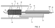
- FIG. 3 illustrates a high level schematic diagram of a partially sectioned view of the distal portion of the temporary endovascular perfusion conduit system of FIG. 1 and a delivery mechanism for intra-arterial administration of a medicament according to an exemplary embodiment
- FIG. 4 illustrates a high level schematic diagram of a sectioned view of a second embodiment of a temporary endovascular conduit system, comprising an expanding device
- FIGS. 5A-5D illustrate high level schematic diagrams of partially sectioned views of the distal portion of the temporary endovascular perfusion conduit system of FIG. 4 , showing sequential steps in the deployment of the expanding device in a vessel according to an exemplary embodiment
- FIG. 6 illustrates a high level schematic diagram of a partially sectioned view of the distal portion of the temporary endovascular perfusion conduit system of FIG. 4 and a delivery mechanism for intra-arterial administration of a medicament according to an exemplary embodiment
- FIG. 7A illustrates a high level schematic diagram of a sectioned view of an embodiment of a temporary endovascular perfusion conduit exhibiting a distal filtering extension member
- FIG. 7B illustrates a high level schematic diagram of a sectioned view of an embodiment of a temporary endovascular perfusion conduit exhibiting a proximal securing member and a distal filtering extension member;
- FIG. 8 illustrates a high level schematic diagram of a sectioned view of an embodiment of a temporary endovascular perfusion conduit comprising a clot retrieval device
- FIG. 9 illustrates a high level flow chart of a method of providing temporary endovascular perfusion and optional clot retrieval.
- FIG. 1 illustrates a high level schematic diagram of a sectioned view of a first embodiment of a temporary endovascular conduit system, denoted temporary endovascular conduit system 50 , deployed in an occlusion 10 occluding a body lumen 15 .
- Temporary endovascular conduit system 50 comprises: a catheter 40 , exhibiting a proximal portion 60 and a distal portion 80 ; a hub 90 ; a pair of members 26 and 26 A; a guide wire 30 ; and a self expanding device 20 , exhibiting a proximal end 22 and a distal end 24 , illustrated in a large diameter state.
- the diameter of body lumen 15 in the area of occlusion 10 is denoted D 2
- the inner diameter of self expanding device 20 in the large diameter state denoted D 1
- D 2 The diameter of body lumen 15 in the area of occlusion 10
- D 1 the inner diameter of self expanding device 20 in the large diameter state
- D 1 is preferably between 1 ⁇ 3 and 1 ⁇ 2 of D 2
- Body lumen 15 is a small blood vessel, exhibiting an inner diameter D 2 of 5 mm or less, as described above.
- providing a conduit exhibiting an inner diameter for blood flow of at least 1 ⁇ 3 of D 2 allows a sufficient blood flow, in the absence of sufficient collateral flow from other arteries, to prevent or delay cell death, since this provides for a resultant stenosis of less than 75%.
- Proximal end 22 of self expanding device 20 is positioned proximally to occlusion 10 and distal end 24 of self expanding device 20 is positioned distally to occlusion 10 .
- Self expanding device 20 in the large diameter state provides a conduit for limited blood flow from proximal end 22 to distal end 24 .
- the length of self expanding device 20 in the large diameter denoted L, is at least 5 times D 1 .
- length L is at least 10 times D 1 .
- length L is at least 15 times D 1 .
- length L is at least 20 times D 1 .
- length L is at least 30 times D 1 .
- length L is at least 14 times D 1 .
- Hub 90 is attached to proximal portion 60 of catheter 40 .
- members 26 and 26 A are respectively connected to proximal end 22 and distal end 24 of self expanding device 20 .
- Members 26 , 26 A and guide wire 30 run through catheter 40 and hub 90 and out therefrom, and are provided to be long enough so as to be accessible.
- the structure of self expanding device 20 can be of any kind, provided it is hollow, including, but not limited to, a tubular tube, a shield tube and a self expanding structure manufactured by any one of weaving, coiling, laser cutting and braiding a plurality of filaments.
- self expanding device 20 is a self expandable braided tubular member, as illustrated.
- the braid construction that forms self expanding device 20 can be produced from many different materials, including, but not limited to, metals, polymers and composites. More specifically, these materials can include cobalt-chrome alloys, stainless steel, nylon, and polyesters.
- superelastic materials such as some nickel titanium alloys, are used.
- a formulation of nickel titanium alloy comprising about 51%-56% nickel and about 44%-49% titanium is used.
- each filament comprising self expanding device 20 has a round cross section, the diameter of the cross section usually ranging between about 0.0005 inches and 0.01 inches and optionally between 0.001 inches and 0.004 inches, and the number of filaments comprising the braided construction ranges between 4 and 288.
- the filaments comprising self expanding device 20 are flat wires with non-circular cross sections, the number of filaments ranging between 8 and 64, optionally between 12 and 24.
- the braiding angle is between 60° and 150°. In one particular embodiment the braiding angle is 90°.
- the braiding pattern is a regular pattern known also as herringbone or 1 ⁇ 2 pattern.
- a braiding pattern of 1 ⁇ 1 is used, with such a braiding pattern also known as a “one over one under” pattern.
- self expanding device 20 is permeable to fluids.
- the inner diameter of self expanding device 20 is in the first small diameter state, denoted D 0 , when self expanding device 20 is held within catheter 40 as illustrated in FIG. 2A described further below.
- D 0 is between 0.5 mm and 1.5 mm, optionally between 0.8 mm and 1.2 mm and diameter D 1 is between 0.8 mm and 2 mm, optionally between 1 mm and 1.5 mm.
- the length of self expanding device 20 stays fixed when the diameter of self expanding device 20 changes, and in other embodiments, the length of self expanding device 20 is reduced when the inner diameter of self expanding device 20 increases.
- self expanding device 20 is substantially not expanded or only slightly expands when elongated to length L.
- the braid construction that forms self expanding device 20 is coated with a non-porous elastic material, illustrated in FIG. 3 as a coating 95 . Coating over the porous braid construction of self expanding device 20 forms a solid tubular conduit within occlusion 10 .
- the elastic material can be any of a plurality of materials, including, but not limited to: polymers such as silicones, polyethers, polyurethanes, polyamides, hydrogels such as polyvinyl alcohol or polyvinyl pyrrolidone, and other polymers suitable for intravascular use; permeable, semi-permeable and non-permeable membranes; and expandable foams.
- the elastic material is preferably formed into a fabric mesh and placed around self expanding device 20 .
- the elastic material is porous, preferably less permeable than self expanding device 20 .
- any particles from occlusion 10 which pass through the relatively small openings forming self expanding device 20 flow out therefrom, thereby avoiding harmful disruption of blood flow or occlusion of a vessel thereof.
- Self expanding device 20 in the large diameter state provides and/or sustains a conduit exhibiting an minimum inner diameter D 1 for sufficient blood flow to the region distal of occlusion 10 and from there to the affected area, thereby reducing the infarction rate of penumbral tissue.
- the effective time window for performing endovascular attempts to remove or disrupt occlusion 10 is expanded. Shortening the length and/or increasing the hollow cross-section diameter of self expanding device 20 may result in greater cerebral blood flow to the region distal to occlusion 10 and from there to the affected area, resulting in a greater reduction in the infarction rate of penumbral tissue.
- length L of self expanding device 20 in a maximum expanded state is provided to be as short as possible, while being longer than the length of occlusion 10 , optionally between 2 mm and 40 mm longer than the length of occlusion 10 , and the diameter of the hollow cross-section of self expanding device 20 in a maximum expanded state is provided to be between 1 ⁇ 3 and 1 ⁇ 2 of diameter D 2 of body lumen 15 , as described above.
- length L is 20 mm, thereby extending 5 mm proximally of occlusion 10 and 5 mm distally of occlusion 10 .
- occlusion 10 is 20-30 mm long, length L between 40 mm and 50 mm, thereby extending between 5 mm and 15 mm proximally of occlusion 10 and between 5 mm and 15 mm distally of occlusion 10 .
- Self expanding device 20 provides enough radial force at diameters up to the unstressed maximum expanded state of 1 ⁇ 2 of D 2 so as to prevent movement of self expanding device 20 in occlusion 10 , while being small enough so as not traumatize the walls of body lumen 15 .
- the inside diameter of self expanding device 20 in its maximum expanded state represents a conduit with a cross section of at least 0.685 mm 2 .
- self expanding device 20 When self expanding device 20 is at its maximum expanded state it is considered to be at its resting state, since no radial expansion force is exhibited by self expanding device 20 , in particular self expanding device 20 does not urge to expand beyond said second large diameter state. Thus, self expanding device 20 may exhibit outward radial force when within occlusion 10 , until expansion has reached the unstressed maximum expanded state of 1 ⁇ 2 of D 2 . Once self expanding device 20 has reached the unstressed maximum expanded state of 1 ⁇ 2 of D 2 no radial force is applied to occlusion 10 . Furthermore no radial force is applied to the walls of body lumen 15 distally and proximally of occlusion 10 .
- Members 26 , 26 A are provided in order to facilitate the deployment of self expanding device 20 into occlusion 10 , particularly aiding in control of localization and further procedures, and/or the ultimate retraction of self expanding device 20 therefrom.
- Members 26 and 26 A are in one embodiment each constituted of one of a flexible rod, a filament or a bundle of filaments.
- the cross section of each of members 26 and 26 A are on the same order as the cross section of guidewire 30 , with guidewire 30 preferably being a 0.014′′ (0.3556 mm) guidewire known to the art exhibiting a cross-sectional area of less than 0.1 mm 2 .
- stretching and compressing of self expanding device 20 is enabled by respectively relatively pulling and pushing members 26 and 26 A to expand and decrease the length between proximal end 22 and distal end 24 .
- Stretching self expanding device 20 reduces its cross-sectional area and enables an operator to change the placement of self expanding device 20 easily.
- Compressing self expanding device 20 enlarges its hollow cross-sectional area so as to allow more blood flow there through, as described above.
- self expanding device 20 can be retracted into catheter 40 by pulling member 26 or by pulling and pushing members 26 , 26 A, respectively, and withdrawn from the patient body along with the retraction of catheter 40 .
- members 26 , 26 A are inherently connected to self expanding device 20 , i.e. members 26 , 26 A are thin local elongated protrusions of self expanding device 20 .
- members 26 , 26 A are thin local elongated protrusions of self expanding device 20 .
- withdrawal of self expanding device 20 comprises reduction in radial size to a size greater than the radial size of self expanding device when first delivered to occlusion 10 .
- self expanding device 20 In order to enable visualization of the construction that forms self expanding device 20 under fluoroscopy, in one embodiment numerous radiopaque materials such as gold, platinum, or tungsten can be applied using various methods such as marker, electroplating, ion deposition, and coating. In some embodiments, self expanding device 20 is at least partially coated with a radiopaque polymer such as silicone mixed with tantalum powder thus providing visualization.
- a radiopaque polymer such as silicone mixed with tantalum powder
- self expanding device 20 is secured in location within occlusion 10 by catheter 40 or by another anchoring means secured externally of the patient body, such as by members 26 , 26 A and 26 B, to be described further below.
- FIGS. 2A-2E illustrate high level schematic diagrams of partially sectioned views of the distal portion of temporary endovascular conduit system 50 of FIG. 1 , showing sequential steps in the deployment of self expanding device 20 within body lumen 15 across occlusion 10 according to an exemplary embodiment, the description of FIGS. 2A-2E being taken together.
- self expanding device 20 is in a collapsed state, i.e. a small diameter state, and secured within catheter 40 , and particularly in a distal portion of catheter 40 .
- Self expanding device 20 is pre-loaded or back-loaded onto guidewire 30 while secured within catheter 40 .
- Guidewire 30 is manipulated through body lumen 15 from an entry site, such as the femoral artery, to the region of body lumen 15 occluded by occlusion 10 .
- a distal tip 32 of guidewire 30 is advanced across occlusion 10 using appropriate guidewire and crossing techniques known in the art. Once distal tip 32 of guidewire 30 passes through the distal end of occlusion 10 , catheter 40 is advanced through occlusion 10 .
- a micro catheter can be used to visualize the patency of both the vasculature proximal to occlusion 10 and the vasculature distal to occlusion 10 using conventional radiographic techniques, prior to advancing catheter 40 over guidewire 30 .
- FIG. 2B temporary endovascular conduit system 50 comprising catheter 40 constraining self expanding device 20 is advanced through occlusion 10 , with distal portion 80 of catheter 40 and distal end 24 of self expanding device 20 extending distally of occlusion 10 .
- a radiographic solution may be injected through hub 90 of FIG. 1 prior to advancing temporary endovascular conduit system 50 into occlusion 10 , thus after the positioning of catheter 40 across occlusion 10 the length of occlusion 10 can be determined, thereby allowing an operator to determine the desired positions of distal end 24 and proximal end 22 of self expanding device 20 .
- determining of the length of occlusion 10 is performed prior to inserting temporary endovascular conduit system 50 in the patient body, thus enabling the operator to choose a specific self expanding device 20 with desired final length and expanded large diameter.
- Various methods can be applied to visualize proximal end 22 and distal end 24 of self expanding device 20 under fluoroscopy, as described above in relation to FIG. 1 .
- catheter 40 is partially retracted from restraining self expanding device 20 , while members 26 , 26 A are held in place, thereby partially releasing self expanding device 20 from catheter 40 through distal portion 80 .
- Due to self expanding properties the exposed part of self expanding device 20 automatically performs an outward radial expansion and preferably forms into a generally circular configuration.
- inner diameter D 1 of self expanding device 20 in the large diameter state is no greater than twice, optionally no greater than 1.5 times, and further optionally no greater than 1.2 times the inner diameter D 0 of self expanding device 20 in the first small diameter state when held within catheter 40 .
- catheter 40 is retracted until self expanding device 20 is fully released.
- Self expanding device 20 expands to its large diameter state, presenting a conduit for blood flow through occlusion 10 .
- Catheter 40 may be fully retracted from the patient body.
- guidewire 30 remains positioned in occlusion 10 to provide guidance for maneuvering medical means to the site of occlusion 10 .
- guidewire 30 is removed from the patient body and member 26 and/or member 26 A provides guidance for maneuvering medical means to the site of occlusion 10 , thus enabling extended medical procedures without the need of guidewire 30 .
- Temporary endovascular conduit system 50 can be fully refracted out of the patient body, whenever necessary. In one embodiment this is accomplished by expanding the length of self expanding device 20 by manipulation of members 26 , 26 A thereby reducing the diameter of self expanding device 20 . Once the diameter of self expanding device 20 has been reduced, catheter 40 is preferably advanced over self expanding device 20 while self expanding device 20 is held in the small diameter state by members 26 , 26 A, and catheter 40 containing therein self expanding device 20 is then removed from the patient body. Alternatively, catheter 40 is held stationary and self expanding device 20 in the small diameter state is withdrawn from the area of occlusion 10 towards distal portion 80 of catheter 40 , and then drawn within catheter 40 . In an alternative embodiment, self expanding device 20 is maintained in the small diameter state by the manipulation of members 26 , 26 A and removed from the patient body by further manipulation of members 26 , 26 A.
- self expanding device 20 may be collapsed and returned within catheter 40 , numerous deployments of self expanding device 20 at various locations may be performed as a single endovascular procedure.
- a member 26 B constituted of one of a flexible rod, a filament or a bundle of filaments is attached to proximal end 22 of self expanding device 20 .
- Member 26 B can be produced by many different techniques, including but not limited to looping, tying, stitching, interweaving, gluing, welding and soldering, to one or more locations within proximal end 22 .
- member 26 B is looped into the collapsible braided construction of proximal end 22 and thus reduces the diameter of self expanding device 20 while tensioned.
- Self expanding device 20 can be retracted into catheter 40 by tensioning holding member 26 B and advancing distal portion 80 of catheter 40 from proximal end 22 to distal end 24 of self expanding device 20 .
- a stopper 27 with an outer diameter fits into the inner diameter of catheter 40 and facilitates deployment of self expanding device 20 into occlusion 10 since stopper 27 is in contact with proximal end 22 of self expanding device 20 when retracting catheter 40 out of its position across occlusion 10 .
- FIG. 3 illustrates a high level schematic diagram of a partially sectioned view of the distal portion of temporary endovascular conduit system 50 of FIG. 1 and a delivery mechanism 70 for intra-arterial administration of t-PA according to an exemplary embodiment, with device 20 illustrated with coating 95 .
- Coating 95 is in some embodiments non-permeable, and in other embodiments permeable.
- Self expanding device 20 is shown in its large diameter state, i.e. its fully expanded uncompressed state, inside occlusion 10 , thereby sustaining at least some blood flow through occlusion 10 , as described above.
- penumbral tissue preservation is facilitated, thereby prolonging the time window for any effective catheter based recanalization procedure, as described above.
- temporary endovascular conduit system 50 is temporarily deployed, so as to supply oxygenated blood to the ischemic penumbrae, and thereafter removed prior to any endovascular procedure for attempting to remove or disrupt occlusion 10 , and optionally redeployed between repeated procedures for attempting to remove or disrupt occlusion 10 .
- temporary endovascular conduit system 50 is deployed prior to any endovascular procedure for recanalization of lumen 15 , and self expanding device 20 remains expanded inside occlusion 10 during the procedure, thereby maintaining blood flow during the procedure.
- coating 95 is permeable, and thus allows for the passage of a fluid from delivery mechanism 70 to occlusion 10 .
- delivery mechanism 70 is preferably delivered to be within self expanding device 20 optionally formed of a mesh exhibiting openings such that fluid exiting delivery mechanism 70 is received to the circumference of self expanding device 20 deployed across occlusion 10 .
- catheter 40 is used as a passage of a fluid from outside of the body to the occlusion site eliminating the need for delivery mechanism 70 .
- Delivery mechanism 70 is manipulated through body lumen 15 from an entry site, such as the femoral artery, to a region proximal to occlusion 10 .
- delivery mechanism 70 can be manipulated over guidewire 30 .
- guidewire 30 has also been removed, or in the embodiment in which temporary endovascular conduit system 50 has not been removed, as illustrated, delivery mechanism 70 can be manipulated over a dedicated additional guidewire and/or through a guiding catheter, or by using any other technique known in the art.
- Delivery mechanism 70 administers a drug such as a neuro-protective agent, or a thrombolytic agent such as t-PA or any other antithrombotic agent into occlusion 10 , thus breaking down occlusion 10 .
- a drug such as a neuro-protective agent, or a thrombolytic agent such as t-PA or any other antithrombotic agent into occlusion 10 , thus breaking down occlusion 10 .
- a drug such as a neuro-protective agent, or a thrombolytic agent such as t-PA or any other antithrombotic agent into occlusion 10 , thus breaking down occlusion 10 .
- a drug such as a neuro-protective agent, or a thrombolytic agent such as t-PA or any other antithrombotic agent into occlusion 10 , thus breaking down occlusion 10 .
- other means of removing or disrupting occlusion 10 such as: thrombolytic agent infusing techniques; distal or
- removing or disrupting occlusion 10 such as: facilitating fibrinolysis by an outside energy source such as ultrasound or laser energy; and mechanical manipulation of occlusion 10 by primary angioplasty and/or by employing stents permanently or transiently, may be used.
- FIG. 4 illustrates a high level schematic diagram of a sectioned view of a second embodiment of a temporary endovascular perfusion conduit system, denoted temporary endovascular perfusion conduit system 150 , deployed in an occlusion 10 occluding a body lumen 15 .
- Temporary endovascular perfusion conduit system 150 comprises: a catheter 40 , exhibiting a proximal portion 60 and a distal portion 80 ; a hub 90 ; a pair of members 126 and 126 A; and an expanding device 120 , exhibiting a proximal end 122 and a distal end 124 , illustrated in a large diameter state.
- a guide wire 30 is also provided.
- the diameter of body lumen 15 in the area of occlusion 10 is denoted D 2
- the inner diameter of expanding device 120 in the large diameter state denoted D 1
- D 2 The diameter of body lumen 15 in the area of occlusion 10
- D 1 the inner diameter of expanding device 120 in the large diameter state
- D 1 is between 1 ⁇ 3 and 1 ⁇ 2 of D 2 .
- Advantageously providing a conduit exhibiting an inner diameter for blood flow of at least 1 ⁇ 3 of D 2 allows a sufficient blood flow, in the absence of sufficient collateral flow from other arteries, to prevent or delay cell death since this provides for a resultant stenosis of less than 75%.
- Proximal end 122 of expanding device 120 is positioned proximally to occlusion 10 and distal end 124 of expanding device 120 is positioned distally to occlusion 10 .
- Expanding device 120 in the large diameter state provides a conduit for limited blood flow from proximal end 122 to distal end 124 .
- the length of expanding device 120 in the large diameter is at least 5 times D 1 .
- length L is at least 10 times D 1 .
- length L is at least 15 times D 1 .
- length L is at least 20 times D 1 .
- length L is at least 30 times D 1 .
- length L is at least 14 times D 1 .
- Hub 90 is attached to proximal portion 60 of catheter 40 .
- members 126 and 126 A are respectively connected to one or both of proximal end 122 and distal end 124 of expanding device 120 .
- member 126 is connected to proximal end 122 of expanding device 120 and member 126 A is connected to distal end 124 of expanding device 120 , as will be described further hereinto below.
- Members 126 and 126 A and guide wire 30 run through catheter 40 and hub 90 and out therefrom, and are provided to be long enough so as to be accessible.
- the structure of expanding device 120 can be of any kind, providing it is hollow, including, but not limited to, a tubular tube, a shield tube and a self expanding structure manufactured by weaving, braiding, laser cutting, or by coiling a filament.
- Optionally expanding device 120 is a self expandable coiled tubular member, as illustrated, formed by winding a filament spirally and closely over a predetermined diameter and arranged such that when in a fully expanded state each wind is in contact with an adjacent wind, thereby forming a solid tubular shape.
- the coil forming expanding device 120 can be produced from many different materials, including, but not limited to, metals, polymers and composites. More specifically, these materials can include cobalt-chrome alloys, stainless steel, nylon, and polyesters.
- expanding device 120 is not self-expandable, but is instead balloon-expandable, shape memory altered by temperature change or externally stretchable without limitation.
- the filament comprising expanding device 120 has a round cross section, the diameter of the cross section usually ranging between about 0.001 inches and 0.006 inches and optionally between 0.001 inches and 0.0035 inches. In another embodiment the filament comprising expanding device 120 is a flat wire with a non-circular cross section.
- the coil forming expanding device 120 is coated with a non-porous elastic material. Coating over the porous coil will form a solid tubular conduit within occlusion 10 .
- the elastic material can be any of a plurality of materials, including, but not limited to: polymers such as silicone, polyethers, polyurethanes, polyamides, hydrogels such as polyvinyl alcohol or polyvinyl pyrrolidone, and other polymers suitable for intravascular use; permeable, semi-permeable and non-permeable membranes; and expandable foams.
- the elastic material is formed into a fabric mesh and placed around expanding device 120 .
- the elastic material is porous, preferably less permeable than expanding device 120 .
- Expanding device 120 in the large diameter state provides and sustains a conduit exhibiting an inner diameter D 1 for sufficient blood flow to the region distal of occlusion 10 and from there to the affected area, thereby reducing the infarction rate of penumbral tissue.
- the effective time window for performing endovascular attempts to remove or disrupt occlusion 10 is expanded. Shortening the length and/or increasing the hollow cross-section diameter of expanding device 120 may result in greater cerebral blood flow to the region distal to occlusion 10 and from there to the affected area, resulting in a greater reduction in the infarction rate of penumbral tissue.
- length L of expanding device 120 in a maximum expanded state is provided to be as short as possible, while being longer than the length of occlusion 10 , optionally between 2 mm and 40 mm longer than the length of occlusion 10 , and the diameter of the hollow cross-section of expanding device 120 in a maximum expanded state is provided to be between 1 ⁇ 3 and 1 ⁇ 2 of diameter D 2 of body lumen 15 , as described above.
- length L is 20 mm, thereby extending 5 mm proximally of occlusion 10 and 5 mm distally of occlusion 10 .
- occlusion 10 is 20-30 mm long
- length L between 40 mm and 50 mm, thereby extending between 5 mm and 15 mm proximally of occlusion 10 and between 5 mm and 15 mm distally of occlusion 10 .
- Expanding device 120 provides enough radial force at diameters up to the unstressed maximum expanded state of 1 ⁇ 2 of D 2 so as to prevent movement of expanding device 120 in occlusion 10 , while being small enough so as not traumatize the walls of body lumen 15 .
- the inside diameter of expanding device 120 in its maximum expanded state represents a conduit with a cross section of at least 0.685 mm 2 .
- expanding device 120 may exhibit outward radial force when within occlusion 10 , until expansion has reached the unstressed maximum expanded state of 1 ⁇ 2 of D 2 . Once expanding device 120 has reached the unstressed maximum expanded state of 1 ⁇ 2 of D 2 no radial force is applied to occlusion 10 . Furthermore no radial force is applied to the walls of body lumen 15 distally and proximally of occlusion 10 .
- the hollow cross-sectional area of expanding device 120 is small enough so as to allow simultaneous use of expanding device 120 and a device for dislodging, removing and/or dissolving the clot, as will be described below in relation to FIG. 6 .
- expanding device 120 is secured in location within occlusion 10 by catheter 40 or by another anchoring means secured externally of the patient body, such as by members 126 , 126 A or 126 B to be described further below
- Optional members 126 , 126 A are provided in order to facilitate the deployment of expanding device 120 into occlusion 10 particularly aiding in control of localization and further procedures, and/or the ultimate refraction of expanding device 120 therefrom.
- Members 126 and 126 A are in one embodiment each constituted of one of a flexible rod, a filament or a bundle of filaments.
- the cross section of each of members 126 and 126 A are on the same order as the cross section of guidewire 30 , with guidewire 30 preferably being a 0.014′′ (0.3556 mm) guidewire known to the art exhibiting a cross-sectional area of less than 0.1 mm 2 .
- stretching and compressing of expanding device 120 is enabled by respectively relatively pulling and pushing members 126 and 126 A to expand and decrease the length between proximal end 122 and distal end 124 .
- Stretching expanding device 120 reduces its cross-sectional area and enables an operator to change the placement of expanding device 120 easily.
- Compressing expanding device 120 enlarges its hollow cross-sectional area so as to allow more blood flow there through, as described above.
- expanding device 120 can be refracted into the catheter 40 using members 126 , 126 A and withdrawn from the patient body along with the retraction of catheter 40 .
- members 126 , 126 A are inherently connected to expanding device 120 , i.e. members 126 , 126 A are thin local elongated protrusions of expanding device 120 .
- withdrawal of expanding device 120 comprises reduction in radial size to a size greater than the radial size of expanding device when first delivered to occlusion 10 .
- radiopaque materials such as gold, platinum, or tungsten can be applied using various methods such as marker, electroplating, ion deposition, and coating.
- expanding device 120 is coated with a radiopaque polymer such as silicone mixed with tantalum powder.
- FIGS. 5A-5E illustrate high level schematic diagrams of partially sectioned views of the distal portion of temporary endovascular perfusion conduit system 150 of FIG. 4 , showing sequential steps in the deployment of expanding device 120 within body lumen 15 across occlusion 10 according to an exemplary embodiment, the description of FIGS. 5A-5D being taken together.
- expanding device 120 is in a collapsed state, i.e. a small diameter state, and secured within catheter 40 , and particularly in a distal portion of catheter 40 . Expanding device 120 is pre-loaded or back-loaded onto guidewire 30 while secured within catheter 40 .
- Guidewire 30 is manipulated through body lumen 15 from an entry site, such as the femoral artery, to the region of body lumen 15 occluded by occlusion 10 .
- a distal tip 32 of guidewire 30 is advanced across occlusion 10 using appropriate guidewire and crossing techniques known in the art. Once distal tip 32 of guidewire 30 passes through the distal end of occlusion 10 , catheter 40 is advanced through occlusion 10 .
- a micro catheter can be used to visualize the patency of both the vasculature proximal to occlusion 10 and the vasculature distal to occlusion 10 using conventional radiographic techniques, prior to advancing catheter 40 over guidewire 30 .
- FIG. 5B temporary endovascular conduit system 150 comprising catheter 40 constraining expanding device 120 is advanced through occlusion 10 , with distal portion 80 of catheter 40 and distal end 124 of expanding device 120 extending distally of occlusion 10 .
- a radiographic solution may be injected through hub 90 of FIG. 4 prior to advancing temporary endovascular conduit system 150 into occlusion 10 , thus after the positioning of catheter 40 across occlusion 10 the length of occlusion 10 can be determined, thereby allowing an operator to determine the desired positions of distal end 124 and proximal end 122 of expanding device 120 .
- determining of the length of occlusion 10 is performed prior to inserting temporary endovascular conduit system 150 in the patient body, thus enabling the operator to choose a specific expanding device 120 with a desired final length and expanded large diameter.
- Various methods can be applied to visualize proximal end 122 and distal end 124 of expanding device 120 under fluoroscopy, as described above in relation to FIG. 4 .
- catheter 40 is partially retracted from expanding device 120 while members 126 , 126 A are held in place, thereby partially releasing expanding device 120 from catheter 40 through distal portion 80 .
- expanding device 120 is self expandable, due to self expanding properties the exposed part of expanding device 120 automatically performs an outward radial expansion and preferably forms into a generally circular configuration.
- inner diameter D 1 of expanding device 120 in the large diameter state is no greater than twice, optionally no greater than 1.5 times, and further optionally no greater than 1.2 times the inner diameter of expanding device 120 in the first small diameter state when held within catheter 40 , denoted D 0 .
- catheter 40 is retracted until expanding device 120 is fully released. Expanding device 120 expands to its large diameter state presenting a conduit for blood flow through occlusion 10 .
- Catheter 40 may be fully retracted from the patient body.
- guidewire 30 remains positioned in occlusion 10 to provide guidance for maneuvering medical means to the site of occlusion 10 .
- guidewire 30 is removed from the patient body and member 126 and/or member 126 A provides guidance for maneuvering medical means to the site of occlusion 10 , thus enabling extended medical procedures without the need of a guide wire 30 .
- Temporary endovascular perfusion conduit system 150 can be fully retracted out of the patient body, whenever necessary. In one embodiment this is accomplished by expanding the length of expanding device 120 by manipulation of members 126 , 126 A thereby reducing the diameter of expanding device 120 . Once the diameter of expanding device 120 has been reduced, catheter 40 is preferably advanced over expanding device 120 while expanding device 120 is held in the small diameter state by members 126 , 126 A, and catheter 40 containing therein expanding device 120 is then removed from the patient body. Alternatively, catheter 40 is held stationary and expanding device 120 in the small diameter state is withdrawn from the area of occlusion 10 towards proximal end 80 of catheter 40 , and then drawn within catheter 40 .
- expanding device 120 is maintained in the small diameter state by the manipulation of members 126 , 126 A and removed from the patient body by further manipulation of members 126 , 126 A.
- expanding device 120 may be collapsed and returned within catheter 40 , numerous deployments of expanding device 120 at various locations may be performed as a single endovascular procedure.
- expanding device 120 can be retracted into catheter 40 by a holding member 126 B by tensioning holding member 26 B and advancing distal portion 80 of catheter 40 from proximal end 122 to distal end 124 of expanding device 120 .
- a stopper 27 exhibiting an outer diameter fits into the inner diameter of catheter 40 and facilitates the deployment of expanding device 120 into occlusion 10 by keeping stopper 27 in constant contact against the proximal end 122 of expanding device 120 and pushing it gradually during the retraction of catheter 40 out of its position across occlusion 10 .
- FIG. 6 illustrates a high level schematic diagram of a partially sectioned view of the distal portion of temporary endovascular perfusion conduit system 150 of FIG. 4 and a delivery mechanism 70 for intra-arterial administration of t-PA according to an exemplary embodiment.
- Expanding device 120 is shown in its large diameter state, i.e. its fully expanded uncompressed state, inside occlusion 10 , thereby sustaining at least some blood flow through occlusion 10 , as described above.
- penumbral tissue preservation is facilitated, thereby prolonging the time window for any effective catheter based recanalization procedure, as described above.
- temporary endovascular perfusion conduit system 150 is temporarily deployed, so as to supply oxygenated blood to the ischemic penumbrae, and thereafter removed prior to any endovascular procedure for attempting to remove or disrupt occlusion 10 , and optionally redeployed between repeated procedures for attempting to remove or disrupt occlusion 10 .
- temporary endovascular perfusion conduit system 150 is deployed prior to any endovascular procedure for attempting to remove or disrupt occlusion 10 , and expanding device 120 remains expanded inside occlusion 10 during the procedure, thereby maintaining blood flow during the procedure.
- expanding device 120 is permeable, and thus allows for the passage of a fluid from delivery mechanism 70 to occlusion 10 .
- delivery mechanism 70 is preferably delivered to be within expanding device 120 optionally formed as a spiral winding wherein successive turns are not in contact with previous turns thus forming a structure such that fluid exiting delivery mechanism 70 is received to the circumference of expanding device 120 deployed across occlusion 10 .
- catheter 40 is used as a passage of a fluid from outside of the body to the occlusion site eliminating the need for delivery mechanism 70 .
- Delivery mechanism 70 is manipulated through body lumen 15 from an entry site, such as the femoral artery, to a region proximal to occlusion 10 .
- delivery mechanism 70 can be manipulated over guidewire 30 .
- guidewire 30 has also been removed, or in the embodiment in which temporary endovascular perfusion conduit system 150 has not been removed, as illustrated, delivery mechanism 70 can be manipulated over a dedicated additional guidewire and/or through a guiding catheter, or by using any other technique known in the art.
- Delivery mechanism 70 administers a drug such as a neuro-protective agent, or a thrombolytic agent such as t-PA, or any other antithrombotic agent, into occlusion 10 , thus breaking down occlusion 10 .
- a drug such as a neuro-protective agent, or a thrombolytic agent such as t-PA, or any other antithrombotic agent
- thrombolytic agent infusing techniques such as: thrombolytic agent infusing techniques; distal or proximal embolectomy devices; various wire corkscrews and baskets; clot capturing devices;
- removing or disrupting occlusion 10 such as: facilitating fibrinolysis by an outside energy source such as ultrasound or laser energy; and mechanical manipulation of occlusion 10 by primary angioplasty and/or by employing stents permanently or transiently, may be used.
- FIG. 7A illustrates a high level schematic diagram of a sectioned view of an embodiment of a temporary endovascular perfusion conduit 220 exhibiting a distal filtering extension member 240 , coupled to distal end 24 of self expanding device 20 via transition portion 230 .
- Self expanding device 20 is substantially as described above in relation to FIG. 1 , exhibiting an inner diameter between 1 ⁇ 3 and 1 ⁇ 2 of D 2 , i.e. the diameter of body lumen 15 in the area of occlusion 10 .
- distal filtering extension member 240 is sized so as to meet the inner walls of lumen 15 in the area distal of occlusion 10 .
- distal filtering extension member 240 is arranged to be at the resting state for diameters of 0.25 mm-1.5 mm larger than the inner walls of lumen 15 in the area distal of occlusion 10 , thus ensuring that distal filtering extension member 240 meets the inner walls of lumen 15 and further optionally provides a securing or anchoring functionality.
- Transition portion 230 is optionally a flared portion, and both transition portion 230 and distal filtering extension member 240 may be provided in a single integrated braid using an appropriately shaped mandrel, as described in U.S. Pat. No. 7,093,527 issued Aug.
- distal filtering extension member 240 is arranged to trap particles greater than a predetermined size.
- the predetermined size is 500 microns.
- the predetermined size is 350 microns.
- the predetermined size is 200 microns, and in yet another embodiment the predetermined size is 80 microns.
- transition portion 230 and distal filtering extension member 240 are of a different element than that of temporary endovascular perfusion conduit 220 , such as of silicon or rubber.
- the distal portion of distal filtering extension member 240 may be open, may exhibit a filter, or be closed in the area opposing transition portion 230 without exceeding the scope.
- the filter of distal filtering extension member 240 may be more or less permeable than the walls of temporary endovascular perfusion conduit 220 without exceeding the scope.
- FIG. 7B illustrates a high level schematic diagram of a sectioned view of an embodiment of a temporary endovascular perfusion conduit 320 exhibiting distal filtering extension member 240 coupled to distal end 24 of self expanding device 20 via transition portion 230 , and further exhibiting a proximal securing member 330 coupled to proximal end 22 of self expanding device 20 via a transition portion 340 .
- Self expanding device 20 is substantially as described above in relation to FIG. 1 , exhibiting an inner diameter between 1 ⁇ 3 and 1 ⁇ 2 of D 2 , i.e. the diameter of body lumen 15 in the area of occlusion 10 and distal filtering extension member 240 is substantially as described above in relation to FIG. 7A .
- Proximal securing member 330 is preferably sized so as to meet the inner walls of lumen 15 in the area proximal of occlusion 10 , thus occlusion 10 is completely encased by the combination of self expanding device 20 , distal filtering extension member 240 and proximal securing member 330 .
- proximal securing member 330 is arranged to be at resting state for diameters of 0.25 mm-1.5 mm larger than the inner walls of lumen 15 in the area proximal of occlusion 10 , thus ensuring that proximal securing member 330 meets the inner walls of lumen 15 , thus securing particles detached from occlusion 10 to flow out therefrom, thereby avoiding harmful disruption of blood flow or occlusion of a vessel thereof, and optionally providing a securing or anchoring functionality.
- Transition portion 340 is preferably a flared portion, and both transition portion 340 and proximal securing member 340 may be provided in a single integrated braid using an appropriately shaped mandrel, as described in U.S. Pat. No. 7,093,527 incorporated above by reference.
- FIG. 8 illustrates a high level schematic diagram of a sectioned view of an embodiment of a temporary endovascular perfusion conduit 420 comprising a clot retrieval device 430 in communication with self expanding device 20 shown disposed within body lumen 15 at occlusion 10 .
- Self expanding device 20 is in all respects similar to self expanding device 20 of FIG. 1 , with the addition of clot retrieval device 430 constituted of an additional braid external to that of self expanding device 20 .
- Clot retrieval device 430 is arranged to be at resting state for diameters of 0.5 mm-1.5 mm larger than the inner walls of lumen 15 in the area distal of occlusion 10 , thus meet the inner walls of body lumen 15 .
- Clot retrieval device 430 is in an exemplary embodiment an open braid having 1 ⁇ 2 or less of the number of filaments constituting self expanding device 20 , and thus expands to trap within clot retrieval device 430 portions 440 of occlusion 10 .
- Retrieval of clot retrieval device 430 preferably in combination with retrieval of self expanding device 20 thus removes at least a portion of occlusion 10 from body lumen 15 while providing and/or sustaining a conduit for blood passage having a diameter for sufficient blood flow to the region distal of occlusion 10 .
- distal filtering extension member 240 described above in relation to FIG. 7A is further provided.
- axial motion of clot retrieval device 430 may break apart a portion of occlusion 10 .
- clot retrieval device 430 is provided in cooperation with distal filtering extension member 240 of FIG. 7A , thus distal filtering extension member 240 is arranged to trap any portions of occlusion 10 which have been broken apart by clot retrieval device 430 .
- Production of temporary endovascular perfusion conduit 420 is in one embodiment performed by braiding self expanding device 20 with additional filaments coupled to inherent structural filaments of self expanding device 20 , the additional filaments will ultimately appear only in clot retrieval device 430 .
- Section 450 of self expanding device 20 is braided, and the additional filaments are removed from the braiding machine, so that the balance of self expanding device 20 will not exhibit the additional filaments. Braiding of self expanding device 20 continues up to section 460 .
- the filaments of self expanding device 20 are removed from the braiding machine, and a tube with an inner diameter larger than that of self expanding device 20 and an outer diameter of the desired size at the resting state of clot retrieval device 430 is placed over the braided portion of self expanding device 20 .
- the additional filaments of portion 450 are then braided over the tube, up to section 460 .
- the tube is then removed, and all filaments, including the filaments of self expanding device 20 and the additional filaments are braided to completely form section 460 .
- temporary endovascular perfusion conduit 420 is a braided device, however this is not meant to be limiting in any way.
- temporary endovascular perfusion conduit 430 is manufactured by any one of weaving, coiling and laser cutting.
- FIG. 9 illustrates a high level flow chart of a method of providing temporary endovascular perfusion and optional clot retrieval.
- an expandable tubular body is provided, preferably selected so as to exhibit a first small diameter state and a second large diameter state.
- the expandable tubular body exhibits a diameter in the second large diameter state no more than 50% of the diameter of a target blood vessel at the sight of the occlusion.
- the length of the expandable tubular body of stage 1000 is selected so as to be at least 14 times the inner diameter of the expandable tubular body in the second large diameter state.
- the inner diameter of the expandable tubular body of stage 1000 in the large diameter state is selected so as to be no greater than twice the diameter of the expandable tubular body of stage 1000 in the small diameter state.
- the inner diameter of the small diameter state may not be inherent, and in an exemplary embodiment is defined by the parameters of the delivery catheter, such as catheter 40 .
- the expandable tubular body of stage 1000 is advanced in the small diameter state through the occlusion.
- a distal portion or a tip of the catheter is first broached through the occlusion thereby opening and/or widening a passage therethrough, later to be occupied and sustained by the expandable tubular body, as the catheter is further advanced.
- the expandable tubular body is manipulated through the body and advanced through the occlusion while loaded onto the distal portion of a delivery catheter, such as catheter 40 .
- stage 1040 the advanced tubular body of stage 1030 is expanded towards the second large diameter state, thus providing a conduit through the expanded tubular body to maintain blood flow patency through the occlusion.
- the expansion be complete to the second large diameter state, and the only requirement is that sufficient blood flow patency is restored by providing blood flow of at least 25% of the unoccluded blood flow volume.
- no additional radial force is supplied by the expanded tubular body to the occlusion, thus preventing unintended and uncontrolled break up.
- a medicament is delivered to the occlusion.
- the tubular body is permeable by the medicament when in the second large diameter state and thus the medicament is delivered through the tubular body to the occlusion surrounding the tubular body.
- a distal filtering extension is provided distal of the tubular body of stage 1000 , the distal filtering extension being expanded to meet the blood vessel walls distal of the occlusion.
- the distal filtering extension traps any dislodged fragments of the occlusion.
- a proximal securing mechanism is provided proximal of the tubular body of stage 1000 , the proximal securing mechanism being expanded to meet the blood vessel walls proximal of the occlusion.
- the proximal securing mechanism secures the occlusion and its potentially damaging fragments from dislodging and proceeding further into the bloodstream.
- the tubular body is contracted, preferably to the first diameter state, and withdrawn from the blood vessel.
- a portion of the occlusion is withdrawn along with the tubular body.
- the present embodiments enable a conduit system passively perfusing oxygenated blood through an obstructing clot and allowing for clot retrieval.
- This is accomplished in certain embodiments by inserting the conduit system into an occluded blood vessel providing for at least partial blood flow through the occluded blood vessel, thereby reducing the infarction rate of penumbral tissue.
- this is achieved by providing a conduit system exhibiting a collapsible conduit.
- the conduit system is placed inside the clot occluding the occluded blood vessel.
- the collapsible conduit is then expanded, forming a conduit inside the clot, thereby allowing at least partial blood flow therethrough.
Abstract
Description
- The invention relates generally to the field of medical devices, specifically to medical devices that are useful in treating stroke, and more particularly to a device allowing for the flow of oxygenated blood through an obstructed artery thus sustaining at least partial patency.
- Stroke is a leading cause of disability, death and health care expenditure. Most strokes are ischemic, i.e. caused by a decrease in the blood supply to a portion of the brain due to a clot obstructing the flow of blood. A total or hemodynamically significant occlusion of a cerebral artery in an acute ischemic stroke is mostly due to thrombus formation, an embolus, and/or other unwanted matter. When an artery is obstructed, tissue ischemia (lack of oxygen and nutrients) quickly develops. The organ most sensitive to ischemia is the brain. Ischemia will rapidly progress to tissue infarction (cell death) if the occlusion of blood flow persists. In patients experiencing a typical large vessel acute ischemic stroke, it has been estimated that within each hour of no cerebral perfusion, about 20 million neurons are lost. Therefore, cerebral artery occlusions that lead to stroke require swift and effective therapy to reduce the morbidity associated with the disease. The term occlusion as used herein is meant to include any partial or complete blockage of a blood vessel, as by thrombosis, embolism or gradual narrowing.
- The functionally impaired region that surrounds the infarct core and is threatened by cell death has been termed the ischemic penumbra. The ischemic penumbra, although physiologically impaired, is potentially salvageable tissue, however the window of opportunity for recovery of the reversibly injured neurons in the ischemic penumbra is relatively short. Failure to timely restore blood flow triggers a biochemical and metabolic cascade ultimately leading to irreversible brain injury by progressive transformation of the ischemic penumbra into infarcted tissue, i.e. the infarct core expands as the penumbra tissue experiences necrosis.
- Traditionally, emergency management of acute ischemic stroke consisted of mainly general supportive care, e.g. hydration, monitoring neurological status, blood pressure control, and/or anti-platelet or anti-coagulation therapy. In 1996 intra-arterial administration of tissue plasminogen activator (t-PA) was approved by the FDA for the treatment of acute ischemic stroke in selected cases within the first few hours from onset. More recently percutaneous catheter-based technologies have been advanced, including: placing a microcatheter near the clot and infusing a thrombolytic agent in order to dissolve the clot; extracting the clot by distal embolectomy devices in which various wire corkscrews and baskets are advanced distally through the clot in order to capture it; and using proximal devices in which the clot is aspirated or captured and removed. Other methods of removing or disrupting the clot, include: facilitating fibrinolysis by an outside energy source such as ultrasound or laser energy; mechanical manipulation of the clot by primary angioplasty; and employing stents permanently or transiently are also widely used.
- Often, more than one method is required until arterial patency is restored. Such treatment approaches have a common purpose of restoring artery patency as quickly as possible by removing or disrupting the obstructing clot. Achieving artery patency by any of these above methods or any combination of them (multimodal therapy) is often complex, requires multiple steps and is time consuming. Even if the treatment is successful, during the treatment progressive transformation of the penumbra into infarcted tissue occurs.
- A key therapeutic goal of acute ischemic stroke treatment consists of re-establishment of arterial potency prior to cell death. The sooner arterial patency is achieved the greater the clinical benefit, therefore early restoration of blood flow in the affected territory of the brain may save brain tissue.
- Cells within an infarction zone have dramatically reduced blood flow to less than 20% of normal blood flow. As a result, cells within this infarction zone will be irreversibly damaged within a few minutes. The blood flow in the ischemic penumbra, surrounding the infarction zone, is between 20% and 50% of normal. Cells in this area are endangered, but not irreversibly damaged. Studies have indicated that a critical focal stenosis of ˜75% decrease in diameter is usually required to compromise flow in a major cerebral artery, in face of insufficient collateral flow from other arteries.
- U.S. Patent Application Publication S/N 2007/0208367 published Sep. 6, 2007 to Fiorella et al is directed to a method of increasing blood flow through an obstructed blood vessel includes providing an expandable member substantially made of a mesh having a plurality of interstices. The expandable member is expanded to bring at least a portion of the member body into contact with the occlusion. An outward radial force is exerted on the occlusion to dislodge at least one fragment from the occlusion and to enhance blood flow through the blood vessel past the occlusion. Disadvantageously, the radial force required may traumatize the blood vessel exhibiting the occlusion. A means for capturing the dislodged fragment is provided, however the blood flow interruption due to the capturing mesh itself induces flow resistance. Additionally, aggregation of the dislodged fragments in the capturing mesh disrupts and subsequently decreases the blood flow.
- U.S. Pat. No. 6,295,990 issued Oct. 2, 2001 to Lewis et al, the entire contents of which is incorporated herein by reference, is addressed to methods for treating total and partial occlusions by employing a perfusion conduit which is penetrated through the occlusive material. Oxygenated blood or other medium is then perfused through the conduit in a controlled manner, preferably at a controlled pressure below the arterial pressure, to maintain oxygenation and relieve ischemia in tissue distal to the occlusion. The device and method of Lewis is based on an elongated solid catheter extending from outside the patient body until penetrating the occlusion. In an embodiment in which passive perfusion is implemented, blood inlet ports are provided near the proximal end with blood outlet ports provided at the distal end. The requirement for inlet and outlet ports fails to take full advantage of the pressure differential between the proximal and distal sides of the occlusion.
- An article by Kelly et al published in Stroke, June 2008 at pages 39: 1770-1773 entitled “Recanalization of an Acute Middle Cerebral Artery Occlusion Using a Self-Expanding, Reconstrainable, Intracranial Microstent as a Temporary Endovascular Bypass is addressed to providing a temporary bypass using a self expanding stent. Disadvantageously, the self expanding stent exerts radial force against the occlusion, which may result in undesired breaking up of the occlusion with significant fragments being dislodged to proceed further into the bloodstream resulting in potential brain damage.
- There is thus a need for a method and apparatus for passively perfusing oxygenated blood through an obstructing clot while minimizing undesired radial force against the occlusion.
- In view of the discussion provided above and other considerations, the present disclosure provides methods and apparatuses for sustaining patency through an occlusion. This is accomplished in certain embodiments by providing a device arranged to provide and/or sustain at least partial patency of a small blood vessel exhibiting an occlusion. The device comprises a tubular body expandable from an initial small diameter state for manipulation adjacent, and/or through, the occlusion of the small blood vessel and a second large diameter state. In some embodiments, the second large diameter is limited to a maximal allowed value, thus preventing undesired radial force against the occlusion. Optionally, the second large diameter state is no more than 50% of the diameter of the blood vessel at the occlusion location. The term small blood vessel as used herein is defined as a blood vessel of 5 mm or less of inner diameter and may be constituted of an intracranial blood vessel.
- In one embodiment the device is a self expanding device. In one embodiment the device in its large diameter state is of a generally circular shape. In one embodiment the device is an expanded collapsible conduit between 2 and 40 millimeters longer than the maximal length of the occlusion.
- Certain embodiments provide for a device arranged to sustain at least partial patency of a small blood vessel exhibiting an occlusion, the device comprising a tubular body exhibiting a first small diameter state for manipulation to, and through, the occlusion of the small blood vessel, the device expandable to a second large diameter state within the occlusion, the inner dimensions of the second large diameter state being no more than 50% of the diameter of the small blood vessel at the occlusion location, the device presenting a conduit through the tubular body for blood flow through the occlusion when in the large diameter state.
- In some embodiments the tubular body in the second large diameter state does not urge to expand beyond 50% of the diameter of the small blood vessel. In some embodiments the tubular body in the second large diameter state exhibits a length at least 14 times the inner diameter of the tubular body in the second large diameter state.
- In some embodiments the tubular body in the second large diameter state exhibits an inner diameter no more than twice the inner diameter of the tubular body in the first small diameter state. In some embodiments the device further comprises a distal filtering extension coupled to a first end of the tubular body. In certain further embodiments the distal filtering extension is arranged to expand to meet the inner wall of the small blood vessel distal of the occlusion. In certain further embodiments the device further comprises a proximal securing member coupled to a second end of the tubular body, opposing the first end, the second securing portion arranged to expand to meet the inner wall of the small blood vessel.
- In some embodiments the device further comprises a retraction mechanism arranged to collapse the device from the second large diameter state within the occlusion, wherein the device may be withdrawn. In some embodiments the device is coated with an elastic non-porous material.
- In some embodiments the device is constituted of self expanding braided filaments. In some embodiment the device further comprises further comprising a clot retrieval device arranged to retrieve at least a portion of the occlusion, the clot retrieval device in communication with the tubular body and exhibiting a diameter greater than 50% of the diameter of the small blood vessel at the occlusion location.
- In some embodiments the tubular body is coated with an elastic porous material. In some embodiments the small blood vessel is an intracranial blood vessel.
- Independently certain embodiments provide for a temporary endovascular conduit system arranged to sustain partial patency of a small blood vessel exhibiting an occlusion, the temporary endovascular conduit system comprising: a catheter exhibiting an inside diameter; a device comprising a tubular body exhibiting a first small diameter state exhibiting an inner diameter less than the catheter inside diameter, the device expandable to a second large diameter state when the device is within the occlusion, the inner diameter of the second large diameter state being no more than 50% of the diameter of the small blood vessel at the occlusion location, the device presenting a conduit through the tubular body for blood flow through the occlusion when in the second large diameter state.
- In some embodiments the tubular body in the second large diameter state does not urge to expand beyond 50% of the diameter of the small blood vessel at the occlusion location. In some embodiments the tubular body in the second large diameter state exhibits a length at least 14 times the inner diameter of the tubular body in the second large diameter state.
- In some embodiments the tubular body in the second large diameter state exhibits an inner diameter no more than twice the inner diameter of the tubular body in the first small diameter state. In some embodiments the device further comprises a distal filtering extension member coupled to a first end of the tubular body. In certain further embodiments the distal filtering extension member is arranged to expand to meet the inner wall of the small blood vessel distal of the occlusion. In certain further embodiments the temporary endovascular conduit system further comprises a proximal securing member coupled to a second end of the tubular body, opposing the first end, the proximal securing member arranged to expand to meet the inner wall of the small blood vessel.
- In some embodiments the temporary endovascular conduit system further comprises a pair of members in communication with the device, the device collapsible from the second large diameter state to the first small diameter state responsive to respective motion of the members. In some embodiments the tubular body is coated with an elastic non-porous material.
- In some embodiments the tubular body is coated with an elastic porous material. In some embodiments the device is constituted of self expanding braided filaments. In some embodiments the temporary endovascular conduit system further comprises a clot retrieval device arranged to retrieve at least a portion of the occlusion, the clot retrieval device in communication with the tubular body and exhibiting a diameter greater than 50% of the diameter of the small blood vessel at the occlusion location.
- In some embodiments the small blood vessel is an intracranial blood vessel. In some embodiments the temporary endovascular conduit system further comprises a member in communication with the device, the device collapsible from the second large diameter state to the first small diameter state responsive to pulling of the member.
- Independently a system for restoring partial patency to a small blood vessel having an inner diameter and an occlusion is provided, the system comprising: a delivery catheter including a shaft having a shaft diameter and a recess adjacent a distal end of the shaft; and a hollow meshed tube deliverable into the small blood vessel and across the occlusion by the delivery catheter when retained in the recess and expandable from a first small diameter that is substantially similar to or less than the shaft diameter to a second large diameter that is substantially smaller than the small blood vessel diameter; wherein the hollow mesh tube is selectively expandable to the second large diameter in the occlusion thereby disassociated from the recess and deployed to sustain a dimension of a passage traveling through the clogged portion previously created by the delivery catheter.
- In some embodiments the second large diameter is no more than 200% of the first small diameter. In some embodiments the second larger diameter is no more than 50% of the small blood vessel diameter at the occlusion. Independently a method of providing blood flow through a target small blood vessel exhibiting an occlusion is provided, the method comprising: selecting an expandable tubular body exhibiting a first small diameter state and a second large diameter state, the inner dimensions of the second large diameter state being no more than 50% of the diameter of the target blood vessel at the occlusion; advancing the selected expandable tubular body while in the first small diameter state through the occlusion; and expanding the selected and advanced expandable tubular body towards the second large diameter state thereby providing a conduit for blood flow through the occlusion, thereby allowing blood to flow through the selected expanded tubular body.
- In some embodiments the selected expandable tubular body in the second large diameter state does not urge to expand beyond 50% of the diameter of the target small blood vessel at the occlusion. In some embodiments the method further comprises: selecting the expandable tubular body such that the further selected expandable tubular body in the second large diameter state exhibits a length at least 14 times the inner diameter of the expandable tubular body in the second large diameter state. In some embodiments the selected expandable tubular body in the second large diameter state exhibits an inner diameter no more than twice the inner diameter of the tubular body in the first small diameter state.
- In some embodiments the selected expandable tubular body further comprises a distal filtering extension coupled to a distal end of the selected expandable tubular body. In some further embodiments the method comprises expanding the distal filtering extension to meet the inner wall of the target blood vessel distal of the occlusion. In some further embodiment the selected expandable tubular body further comprises a proximal securing member coupled to a proximal end of the selected expandable tubular body, the method further comprising expanding the proximal securing member to meet the inner wall of the target small blood vessel proximal of the occlusion.
- In some embodiments the method further comprises: contracting the selected expanded tubular body from the second large diameter state within the occlusion; and withdrawing the contracted selected tubular body from the target small blood vessel. In some further embodiments the contracting is to the first small diameter state.
- In some embodiments the method further comprises delivering a medicament to the occlusion through the selected expanded tubular body. In some embodiments the method further comprises withdrawing at least a portion of the occlusion from the target blood vessel.
- Independently a method of providing blood flow through a target small blood vessel exhibiting an occlusion is provided, the method comprising: providing an expandable tubular body exhibiting a first small diameter state and a second large diameter state, the inner dimensions of the second large diameter state being no more than 50% of the diameter of the target small blood vessel at the occlusion; advancing the provided expandable tubular body while in the first small diameter state through the occlusion; and expanding the provided and advanced expandable tubular body towards the second large diameter state thereby creating a conduit for blood flow through the occlusion, the conduit constituted of the provided expanded tubular body.
- In some embodiments the provided expandable tubular body in the second large diameter state does not urge to expand beyond 50% of the diameter of the target blood vessel at the occlusion. In some embodiments the provided expandable tubular body in the second large diameter state exhibits a length at least 14 times the inner diameter of the expandable tubular body in the second large diameter state. In some embodiments the provided expandable tubular body in the second large diameter state exhibits an inner diameter no more than twice the inner diameter of the tubular body in the first small diameter state.
- In some embodiments the provided expandable tubular body further comprises a distal filtering extension coupled to a distal end of the selected expandable tubular body. In some further embodiments the method further comprises expanding the distal filtering extension to meet the inner wall of the target small blood vessel distal of the occlusion. In some further embodiments the provided expandable tubular body further comprises a proximal securing member coupled to a proximal end of the selected expandable tubular body, the method further comprising expanding the proximal securing member to meet the inner wall of the target small blood vessel proximal of the occlusion.
- In some embodiments the method further comprises: contracting the provided expanded tubular body from the second large diameter state within the occlusion; and withdrawing the contracted provided tubular body from the target small blood vessel. In some embodiments the contracting is to the first small diameter state. In some embodiments the method further comprises delivering a medicament to the occlusion through the provided expanded tubular body. In some embodiments the method further comprises withdrawing at least a portion of the occlusion from the target small blood vessel.
- Additional features and advantages of the invention will become apparent from the following drawings and description.
- For a better understanding of the invention and to show how the same may be carried into effect, reference will now be made, purely by way of example, to the accompanying drawings in which like numerals designate corresponding elements or sections throughout.
- With specific reference now to the drawings in detail, it is stressed that the particulars shown are by way of example and for purposes of illustrative discussion of the preferred embodiments of the present invention only, and are presented in the cause of providing what is believed to be the most useful and readily understood description of the principles and conceptual aspects of the invention. In this regard, no attempt is made to show structural details of the invention in more detail than is necessary for a fundamental understanding of the invention, the description taken with the drawings making apparent to those skilled in the art how the several forms of the invention may be embodied in practice. In the accompanying drawings:
-
FIG. 1 illustrates a high level schematic diagram of a sectioned view of a first embodiment of a temporary endovascular conduit system, comprising a self expanding device; -
FIGS. 2A-2E illustrate high level schematic diagrams of partially sectioned views of the distal portion of the temporary endovascular perfusion conduit system ofFIG. 1 , showing sequential steps in the deployment of the self expanding device in a vessel according to an exemplary embodiment; -
FIG. 3 illustrates a high level schematic diagram of a partially sectioned view of the distal portion of the temporary endovascular perfusion conduit system ofFIG. 1 and a delivery mechanism for intra-arterial administration of a medicament according to an exemplary embodiment; -
FIG. 4 illustrates a high level schematic diagram of a sectioned view of a second embodiment of a temporary endovascular conduit system, comprising an expanding device; -
FIGS. 5A-5D illustrate high level schematic diagrams of partially sectioned views of the distal portion of the temporary endovascular perfusion conduit system ofFIG. 4 , showing sequential steps in the deployment of the expanding device in a vessel according to an exemplary embodiment; -
FIG. 6 illustrates a high level schematic diagram of a partially sectioned view of the distal portion of the temporary endovascular perfusion conduit system ofFIG. 4 and a delivery mechanism for intra-arterial administration of a medicament according to an exemplary embodiment; -
FIG. 7A illustrates a high level schematic diagram of a sectioned view of an embodiment of a temporary endovascular perfusion conduit exhibiting a distal filtering extension member; -
FIG. 7B illustrates a high level schematic diagram of a sectioned view of an embodiment of a temporary endovascular perfusion conduit exhibiting a proximal securing member and a distal filtering extension member; -
FIG. 8 illustrates a high level schematic diagram of a sectioned view of an embodiment of a temporary endovascular perfusion conduit comprising a clot retrieval device; and -
FIG. 9 illustrates a high level flow chart of a method of providing temporary endovascular perfusion and optional clot retrieval. - Before explaining at least one embodiment of the invention in detail, it is to be understood that the invention is not limited in its application to the details of construction and the arrangement of the components set forth in the following description or illustrated in the drawings. The invention is applicable to other embodiments or of being practiced or carried out in various ways. Also, it is to be understood that the phraseology and terminology employed herein is for the purpose of description and should not be regarded as limiting.
-
FIG. 1 illustrates a high level schematic diagram of a sectioned view of a first embodiment of a temporary endovascular conduit system, denoted temporaryendovascular conduit system 50, deployed in anocclusion 10 occluding abody lumen 15. Temporaryendovascular conduit system 50 comprises: acatheter 40, exhibiting aproximal portion 60 and adistal portion 80; ahub 90; a pair ofmembers guide wire 30; and aself expanding device 20, exhibiting aproximal end 22 and adistal end 24, illustrated in a large diameter state. The diameter ofbody lumen 15 in the area ofocclusion 10 is denoted D2, and the inner diameter ofself expanding device 20 in the large diameter state, denoted D1, is preferably between ⅓ and ½ of D2.Body lumen 15 is a small blood vessel, exhibiting an inner diameter D2 of 5 mm or less, as described above. Advantageously, providing a conduit exhibiting an inner diameter for blood flow of at least ⅓ of D2 allows a sufficient blood flow, in the absence of sufficient collateral flow from other arteries, to prevent or delay cell death, since this provides for a resultant stenosis of less than 75%. -
Proximal end 22 ofself expanding device 20 is positioned proximally toocclusion 10 anddistal end 24 ofself expanding device 20 is positioned distally toocclusion 10.Self expanding device 20 in the large diameter state provides a conduit for limited blood flow fromproximal end 22 todistal end 24. In one non-limiting embodiment the length ofself expanding device 20 in the large diameter, denoted L, is at least 5 times D1. In another non-limiting embodiment length L is at least 10 times D1. In another non-limiting embodiment length L is at least 15 times D1. In another non-limiting embodiment length L is at least 20 times D1. In another non-limiting embodiment length L is at least 30 times D1. In one particular non-limiting embodiment length L is at least 14 times D1. Thus, a conduit of sufficient length to extend from a point proximal ofocclusion 10 to a point distal ofocclusion 10 is provided.Hub 90 is attached toproximal portion 60 ofcatheter 40. In oneembodiment members proximal end 22 anddistal end 24 ofself expanding device 20.Members wire 30 run throughcatheter 40 andhub 90 and out therefrom, and are provided to be long enough so as to be accessible. - The structure of
self expanding device 20 can be of any kind, provided it is hollow, including, but not limited to, a tubular tube, a shield tube and a self expanding structure manufactured by any one of weaving, coiling, laser cutting and braiding a plurality of filaments. Optionally,self expanding device 20 is a self expandable braided tubular member, as illustrated. The braid construction that formsself expanding device 20 can be produced from many different materials, including, but not limited to, metals, polymers and composites. More specifically, these materials can include cobalt-chrome alloys, stainless steel, nylon, and polyesters. In one embodiment, superelastic materials such as some nickel titanium alloys, are used. In one particular embodiment a formulation of nickel titanium alloy comprising about 51%-56% nickel and about 44%-49% titanium is used. - In one embodiment each filament comprising
self expanding device 20 has a round cross section, the diameter of the cross section usually ranging between about 0.0005 inches and 0.01 inches and optionally between 0.001 inches and 0.004 inches, and the number of filaments comprising the braided construction ranges between 4 and 288. In another embodiment the filaments comprisingself expanding device 20 are flat wires with non-circular cross sections, the number of filaments ranging between 8 and 64, optionally between 12 and 24. In one embodiment the braiding angle is between 60° and 150°. In one particular embodiment the braiding angle is 90°. In one embodiment the braiding pattern is a regular pattern known also as herringbone or 1×2 pattern. In another embodiment a braiding pattern of 1×1 is used, with such a braiding pattern also known as a “one over one under” pattern. In one embodimentself expanding device 20 is permeable to fluids. The inner diameter ofself expanding device 20 is in the first small diameter state, denoted D0, when self expandingdevice 20 is held withincatheter 40 as illustrated inFIG. 2A described further below. In some embodiments D0 is between 0.5 mm and 1.5 mm, optionally between 0.8 mm and 1.2 mm and diameter D1 is between 0.8 mm and 2 mm, optionally between 1 mm and 1.5 mm. In certain embodiments the length ofself expanding device 20 stays fixed when the diameter ofself expanding device 20 changes, and in other embodiments, the length ofself expanding device 20 is reduced when the inner diameter ofself expanding device 20 increases. Alternatively,self expanding device 20 is substantially not expanded or only slightly expands when elongated to length L. - In one embodiment the braid construction that forms
self expanding device 20 is coated with a non-porous elastic material, illustrated inFIG. 3 as acoating 95. Coating over the porous braid construction ofself expanding device 20 forms a solid tubular conduit withinocclusion 10. The elastic material can be any of a plurality of materials, including, but not limited to: polymers such as silicones, polyethers, polyurethanes, polyamides, hydrogels such as polyvinyl alcohol or polyvinyl pyrrolidone, and other polymers suitable for intravascular use; permeable, semi-permeable and non-permeable membranes; and expandable foams. The elastic material is preferably formed into a fabric mesh and placed aroundself expanding device 20. Optionally, the elastic material is porous, preferably less permeable thanself expanding device 20. - In the absence of a non-porous elastic material coating, any particles from
occlusion 10 which pass through the relatively small openings formingself expanding device 20 flow out therefrom, thereby avoiding harmful disruption of blood flow or occlusion of a vessel thereof. -
Self expanding device 20 in the large diameter state, as shown, provides and/or sustains a conduit exhibiting an minimum inner diameter D1 for sufficient blood flow to the region distal ofocclusion 10 and from there to the affected area, thereby reducing the infarction rate of penumbral tissue. As a result, the effective time window for performing endovascular attempts to remove or disruptocclusion 10 is expanded. Shortening the length and/or increasing the hollow cross-section diameter ofself expanding device 20 may result in greater cerebral blood flow to the region distal toocclusion 10 and from there to the affected area, resulting in a greater reduction in the infarction rate of penumbral tissue. In one embodiment length L ofself expanding device 20 in a maximum expanded state is provided to be as short as possible, while being longer than the length ofocclusion 10, optionally between 2 mm and 40 mm longer than the length ofocclusion 10, and the diameter of the hollow cross-section ofself expanding device 20 in a maximum expanded state is provided to be between ⅓ and ½ of diameter D2 ofbody lumen 15, as described above. In one embodiment, whereocclusion 10 is 10 mm long, length L is 20 mm, thereby extending 5 mm proximally ofocclusion 10 and 5 mm distally ofocclusion 10. In another embodiment, whereocclusion 10 is 20-30 mm long, length L between 40 mm and 50 mm, thereby extending between 5 mm and 15 mm proximally ofocclusion 10 and between 5 mm and 15 mm distally ofocclusion 10.Self expanding device 20 provides enough radial force at diameters up to the unstressed maximum expanded state of ½ of D2 so as to prevent movement ofself expanding device 20 inocclusion 10, while being small enough so as not traumatize the walls ofbody lumen 15. In one non-limiting embodiment, the inside diameter ofself expanding device 20 in its maximum expanded state represents a conduit with a cross section of at least 0.685 mm2. When self expandingdevice 20 is at its maximum expanded state it is considered to be at its resting state, since no radial expansion force is exhibited byself expanding device 20, in particularself expanding device 20 does not urge to expand beyond said second large diameter state. Thus,self expanding device 20 may exhibit outward radial force when withinocclusion 10, until expansion has reached the unstressed maximum expanded state of ½ of D2. Onceself expanding device 20 has reached the unstressed maximum expanded state of ½ of D2 no radial force is applied toocclusion 10. Furthermore no radial force is applied to the walls ofbody lumen 15 distally and proximally ofocclusion 10. -
Members self expanding device 20 intoocclusion 10, particularly aiding in control of localization and further procedures, and/or the ultimate retraction ofself expanding device 20 therefrom.Members members guidewire 30, withguidewire 30 preferably being a 0.014″ (0.3556 mm) guidewire known to the art exhibiting a cross-sectional area of less than 0.1 mm2. In the embodiment in whichmember 26 is connected toproximal end 22 ofself expanding device 20 andmember 26A is connected todistal end 24 ofself expanding device 20, stretching and compressing ofself expanding device 20 is enabled by respectively relatively pulling and pushingmembers proximal end 22 anddistal end 24. Stretchingself expanding device 20 reduces its cross-sectional area and enables an operator to change the placement ofself expanding device 20 easily. Compressingself expanding device 20 enlarges its hollow cross-sectional area so as to allow more blood flow there through, as described above. As will be described below in relation toFIG. 2D ,self expanding device 20 can be retracted intocatheter 40 by pullingmember 26 or by pulling and pushingmembers catheter 40. - In another
embodiment members self expanding device 20, i.e.members self expanding device 20. There is no requirement that asingle catheter 40 be provided for both delivery ofself expanding device 20 and withdrawal ofself expanding device 20. In one embodiment, withdrawal ofself expanding device 20 comprises reduction in radial size to a size greater than the radial size of self expanding device when first delivered toocclusion 10. - In order to enable visualization of the construction that forms
self expanding device 20 under fluoroscopy, in one embodiment numerous radiopaque materials such as gold, platinum, or tungsten can be applied using various methods such as marker, electroplating, ion deposition, and coating. In some embodiments,self expanding device 20 is at least partially coated with a radiopaque polymer such as silicone mixed with tantalum powder thus providing visualization. - Optionally,
self expanding device 20 is secured in location withinocclusion 10 bycatheter 40 or by another anchoring means secured externally of the patient body, such as bymembers -
FIGS. 2A-2E illustrate high level schematic diagrams of partially sectioned views of the distal portion of temporaryendovascular conduit system 50 ofFIG. 1 , showing sequential steps in the deployment ofself expanding device 20 withinbody lumen 15 acrossocclusion 10 according to an exemplary embodiment, the description ofFIGS. 2A-2E being taken together. InFIG. 2A self expanding device 20 is in a collapsed state, i.e. a small diameter state, and secured withincatheter 40, and particularly in a distal portion ofcatheter 40.Self expanding device 20 is pre-loaded or back-loaded ontoguidewire 30 while secured withincatheter 40.Guidewire 30 is manipulated throughbody lumen 15 from an entry site, such as the femoral artery, to the region ofbody lumen 15 occluded byocclusion 10. Adistal tip 32 ofguidewire 30 is advanced acrossocclusion 10 using appropriate guidewire and crossing techniques known in the art. Oncedistal tip 32 ofguidewire 30 passes through the distal end ofocclusion 10,catheter 40 is advanced throughocclusion 10. In one embodiment, afterdistal tip 32 ofguidewire 30 has passed through the distal end ofocclusion 10, a micro catheter can be used to visualize the patency of both the vasculature proximal toocclusion 10 and the vasculature distal toocclusion 10 using conventional radiographic techniques, prior to advancingcatheter 40 overguidewire 30. - In
FIG. 2B temporaryendovascular conduit system 50 comprisingcatheter 40 constrainingself expanding device 20 is advanced throughocclusion 10, withdistal portion 80 ofcatheter 40 anddistal end 24 ofself expanding device 20 extending distally ofocclusion 10. In one embodiment, a radiographic solution may be injected throughhub 90 ofFIG. 1 prior to advancing temporaryendovascular conduit system 50 intoocclusion 10, thus after the positioning ofcatheter 40 acrossocclusion 10 the length ofocclusion 10 can be determined, thereby allowing an operator to determine the desired positions ofdistal end 24 andproximal end 22 ofself expanding device 20. In another embodiment, determining of the length ofocclusion 10 is performed prior to inserting temporaryendovascular conduit system 50 in the patient body, thus enabling the operator to choose a specificself expanding device 20 with desired final length and expanded large diameter. Various methods can be applied to visualizeproximal end 22 anddistal end 24 ofself expanding device 20 under fluoroscopy, as described above in relation toFIG. 1 . - In
FIG. 2C catheter 40 is partially retracted from restrainingself expanding device 20, whilemembers self expanding device 20 fromcatheter 40 throughdistal portion 80. Due to self expanding properties the exposed part ofself expanding device 20 automatically performs an outward radial expansion and preferably forms into a generally circular configuration. Optionally, inner diameter D1 ofself expanding device 20 in the large diameter state is no greater than twice, optionally no greater than 1.5 times, and further optionally no greater than 1.2 times the inner diameter D0 ofself expanding device 20 in the first small diameter state when held withincatheter 40. - In
FIG. 2D catheter 40 is retracted untilself expanding device 20 is fully released.Self expanding device 20 expands to its large diameter state, presenting a conduit for blood flow throughocclusion 10.Catheter 40 may be fully retracted from the patient body. In one embodiment guidewire 30 remains positioned inocclusion 10 to provide guidance for maneuvering medical means to the site ofocclusion 10. In another embodiment guidewire 30 is removed from the patient body andmember 26 and/ormember 26A provides guidance for maneuvering medical means to the site ofocclusion 10, thus enabling extended medical procedures without the need ofguidewire 30. - Temporary
endovascular conduit system 50 can be fully refracted out of the patient body, whenever necessary. In one embodiment this is accomplished by expanding the length ofself expanding device 20 by manipulation ofmembers self expanding device 20. Once the diameter ofself expanding device 20 has been reduced,catheter 40 is preferably advanced overself expanding device 20 whileself expanding device 20 is held in the small diameter state bymembers catheter 40 containing therein self expandingdevice 20 is then removed from the patient body. Alternatively,catheter 40 is held stationary andself expanding device 20 in the small diameter state is withdrawn from the area ofocclusion 10 towardsdistal portion 80 ofcatheter 40, and then drawn withincatheter 40. In an alternative embodiment,self expanding device 20 is maintained in the small diameter state by the manipulation ofmembers members - Advantageously, since
self expanding device 20 may be collapsed and returned withincatheter 40, numerous deployments ofself expanding device 20 at various locations may be performed as a single endovascular procedure. - In another embodiment illustrated in
FIG. 2E , amember 26B constituted of one of a flexible rod, a filament or a bundle of filaments is attached toproximal end 22 ofself expanding device 20.Member 26B can be produced by many different techniques, including but not limited to looping, tying, stitching, interweaving, gluing, welding and soldering, to one or more locations withinproximal end 22. In apreferred embodiment member 26B is looped into the collapsible braided construction ofproximal end 22 and thus reduces the diameter ofself expanding device 20 while tensioned.Self expanding device 20 can be retracted intocatheter 40 by tensioning holdingmember 26B and advancingdistal portion 80 ofcatheter 40 fromproximal end 22 todistal end 24 ofself expanding device 20. In this particular embodiment astopper 27 with an outer diameter fits into the inner diameter ofcatheter 40 and facilitates deployment ofself expanding device 20 intoocclusion 10 sincestopper 27 is in contact withproximal end 22 ofself expanding device 20 when retractingcatheter 40 out of its position acrossocclusion 10. -
FIG. 3 illustrates a high level schematic diagram of a partially sectioned view of the distal portion of temporaryendovascular conduit system 50 ofFIG. 1 and adelivery mechanism 70 for intra-arterial administration of t-PA according to an exemplary embodiment, withdevice 20 illustrated withcoating 95.Coating 95 is in some embodiments non-permeable, and in other embodiments permeable.Self expanding device 20 is shown in its large diameter state, i.e. its fully expanded uncompressed state, insideocclusion 10, thereby sustaining at least some blood flow throughocclusion 10, as described above. Thus, penumbral tissue preservation is facilitated, thereby prolonging the time window for any effective catheter based recanalization procedure, as described above. In one embodiment, temporaryendovascular conduit system 50 is temporarily deployed, so as to supply oxygenated blood to the ischemic penumbrae, and thereafter removed prior to any endovascular procedure for attempting to remove or disruptocclusion 10, and optionally redeployed between repeated procedures for attempting to remove or disruptocclusion 10. In another embodiment, as illustrated inFIG. 3 , temporaryendovascular conduit system 50 is deployed prior to any endovascular procedure for recanalization oflumen 15, andself expanding device 20 remains expanded insideocclusion 10 during the procedure, thereby maintaining blood flow during the procedure. Optionally, coating 95 is permeable, and thus allows for the passage of a fluid fromdelivery mechanism 70 toocclusion 10. In such an embodiment,delivery mechanism 70 is preferably delivered to be withinself expanding device 20 optionally formed of a mesh exhibiting openings such that fluid exitingdelivery mechanism 70 is received to the circumference ofself expanding device 20 deployed acrossocclusion 10. In anotherembodiment catheter 40 is used as a passage of a fluid from outside of the body to the occlusion site eliminating the need fordelivery mechanism 70. -
Delivery mechanism 70 is manipulated throughbody lumen 15 from an entry site, such as the femoral artery, to a region proximal toocclusion 10. In the embodiment in which temporaryendovascular conduit system 50 has been removed and guidewire 30 has been left in place,delivery mechanism 70 can be manipulated overguidewire 30. In the embodiment in which guidewire 30 has also been removed, or in the embodiment in which temporaryendovascular conduit system 50 has not been removed, as illustrated,delivery mechanism 70 can be manipulated over a dedicated additional guidewire and/or through a guiding catheter, or by using any other technique known in the art.Delivery mechanism 70 administers a drug such as a neuro-protective agent, or a thrombolytic agent such as t-PA or any other antithrombotic agent intoocclusion 10, thus breaking downocclusion 10. In another embodiment, other means of removing or disruptingocclusion 10, such as: thrombolytic agent infusing techniques; distal or proximal embolectomy devices; various wire corkscrews and baskets; clot capturing devices; and clot aspiration and removing devices, can be used. Other methods of removing or disruptingocclusion 10, such as: facilitating fibrinolysis by an outside energy source such as ultrasound or laser energy; and mechanical manipulation ofocclusion 10 by primary angioplasty and/or by employing stents permanently or transiently, may be used. -
FIG. 4 illustrates a high level schematic diagram of a sectioned view of a second embodiment of a temporary endovascular perfusion conduit system, denoted temporary endovascularperfusion conduit system 150, deployed in anocclusion 10 occluding abody lumen 15. Temporary endovascularperfusion conduit system 150 comprises: acatheter 40, exhibiting aproximal portion 60 and adistal portion 80; ahub 90; a pair ofmembers device 120, exhibiting aproximal end 122 and adistal end 124, illustrated in a large diameter state. Aguide wire 30 is also provided. The diameter ofbody lumen 15 in the area ofocclusion 10 is denoted D2, and the inner diameter of expandingdevice 120 in the large diameter state denoted D1, is between ⅓ and ½ of D2. Advantageously providing a conduit exhibiting an inner diameter for blood flow of at least ⅓ of D2 allows a sufficient blood flow, in the absence of sufficient collateral flow from other arteries, to prevent or delay cell death since this provides for a resultant stenosis of less than 75%.Proximal end 122 of expandingdevice 120 is positioned proximally toocclusion 10 anddistal end 124 of expandingdevice 120 is positioned distally toocclusion 10. Expandingdevice 120 in the large diameter state provides a conduit for limited blood flow fromproximal end 122 todistal end 124. Optionally, the length of expandingdevice 120 in the large diameter, denoted L, is at least 5 times D1. In another non-limiting embodiment length L is at least 10 times D1. In another non-limiting embodiment length L is at least 15 times D1. In another non-limiting embodiment length L is at least 20 times D1. In another non-limiting embodiment length L is at least 30 times D1. In one particular non-limiting embodiment length L is at least 14 times D1. Thus, a conduit of sufficient length to extend from a point proximal ofocclusion 10 to a point distal ofocclusion 10 is provided. -
Hub 90 is attached toproximal portion 60 ofcatheter 40. In oneembodiment members proximal end 122 anddistal end 124 of expandingdevice 120. In oneparticular embodiment member 126 is connected toproximal end 122 of expandingdevice 120 andmember 126A is connected todistal end 124 of expandingdevice 120, as will be described further hereinto below.Members wire 30 run throughcatheter 40 andhub 90 and out therefrom, and are provided to be long enough so as to be accessible. - The structure of expanding
device 120 can be of any kind, providing it is hollow, including, but not limited to, a tubular tube, a shield tube and a self expanding structure manufactured by weaving, braiding, laser cutting, or by coiling a filament. Optionally expandingdevice 120 is a self expandable coiled tubular member, as illustrated, formed by winding a filament spirally and closely over a predetermined diameter and arranged such that when in a fully expanded state each wind is in contact with an adjacent wind, thereby forming a solid tubular shape. The coil forming expandingdevice 120 can be produced from many different materials, including, but not limited to, metals, polymers and composites. More specifically, these materials can include cobalt-chrome alloys, stainless steel, nylon, and polyesters. In a preferred embodiment, superelastic materials such as some nickel titanium alloys, are used. Further preferably, a formulation of nickel titanium alloy comprising about 51%-56% nickel and about 44%-49% titanium is used. Optionally, expandingdevice 120 is not self-expandable, but is instead balloon-expandable, shape memory altered by temperature change or externally stretchable without limitation. - In one embodiment the filament comprising expanding
device 120 has a round cross section, the diameter of the cross section usually ranging between about 0.001 inches and 0.006 inches and optionally between 0.001 inches and 0.0035 inches. In another embodiment the filament comprising expandingdevice 120 is a flat wire with a non-circular cross section. - In one embodiment (not shown) the coil forming expanding
device 120 is coated with a non-porous elastic material. Coating over the porous coil will form a solid tubular conduit withinocclusion 10. The elastic material can be any of a plurality of materials, including, but not limited to: polymers such as silicone, polyethers, polyurethanes, polyamides, hydrogels such as polyvinyl alcohol or polyvinyl pyrrolidone, and other polymers suitable for intravascular use; permeable, semi-permeable and non-permeable membranes; and expandable foams. The elastic material is formed into a fabric mesh and placed around expandingdevice 120. Optionally, the elastic material is porous, preferably less permeable than expandingdevice 120. - In the absence of a non-porous elastic material coating any particles from
occlusion 10 which pass through the relatively small openings forming expandingdevice 120 flow out therefrom, thereby avoiding harmful disruption of blood flow or occlusion of a vessel thereof. - Expanding
device 120 in the large diameter state, as shown, provides and sustains a conduit exhibiting an inner diameter D1 for sufficient blood flow to the region distal ofocclusion 10 and from there to the affected area, thereby reducing the infarction rate of penumbral tissue. As a result, the effective time window for performing endovascular attempts to remove or disruptocclusion 10 is expanded. Shortening the length and/or increasing the hollow cross-section diameter of expandingdevice 120 may result in greater cerebral blood flow to the region distal toocclusion 10 and from there to the affected area, resulting in a greater reduction in the infarction rate of penumbral tissue. In one embodiment length L of expandingdevice 120 in a maximum expanded state is provided to be as short as possible, while being longer than the length ofocclusion 10, optionally between 2 mm and 40 mm longer than the length ofocclusion 10, and the diameter of the hollow cross-section of expandingdevice 120 in a maximum expanded state is provided to be between ⅓ and ½ of diameter D2 ofbody lumen 15, as described above. In one embodiment, whereocclusion 10 is 10 mm long, length L is 20 mm, thereby extending 5 mm proximally ofocclusion 10 and 5 mm distally ofocclusion 10. In another embodiment, whereocclusion 10 is 20-30 mm long, length L between 40 mm and 50 mm, thereby extending between 5 mm and 15 mm proximally ofocclusion 10 and between 5 mm and 15 mm distally ofocclusion 10. - Expanding
device 120 provides enough radial force at diameters up to the unstressed maximum expanded state of ½ of D2 so as to prevent movement of expandingdevice 120 inocclusion 10, while being small enough so as not traumatize the walls ofbody lumen 15. In one non-limiting embodiment, the inside diameter of expandingdevice 120 in its maximum expanded state represents a conduit with a cross section of at least 0.685 mm2. When expandingdevice 120 is at its maximum expanded state it is considered at resting state, since no radial expansion force is exhibited by expandingdevice 120, in particular expandingdevice 120 does not urge to expand beyond said second large diameter state. Thus, expandingdevice 120 may exhibit outward radial force when withinocclusion 10, until expansion has reached the unstressed maximum expanded state of ½ of D2. Once expandingdevice 120 has reached the unstressed maximum expanded state of ½ of D2 no radial force is applied toocclusion 10. Furthermore no radial force is applied to the walls ofbody lumen 15 distally and proximally ofocclusion 10. - Further preferably the hollow cross-sectional area of expanding
device 120 is small enough so as to allow simultaneous use of expandingdevice 120 and a device for dislodging, removing and/or dissolving the clot, as will be described below in relation toFIG. 6 . - Optionally, expanding
device 120 is secured in location withinocclusion 10 bycatheter 40 or by another anchoring means secured externally of the patient body, such as bymembers -
Optional members device 120 intoocclusion 10 particularly aiding in control of localization and further procedures, and/or the ultimate refraction of expandingdevice 120 therefrom.Members members guidewire 30, withguidewire 30 preferably being a 0.014″ (0.3556 mm) guidewire known to the art exhibiting a cross-sectional area of less than 0.1 mm2. In the embodiment in whichmember 126 is connected toproximal end 122 of expandingdevice 120 andmember 126A is connected todistal end 124 of expandingdevice 120, stretching and compressing of expandingdevice 120 is enabled by respectively relatively pulling and pushingmembers proximal end 122 anddistal end 124. Stretching expandingdevice 120 reduces its cross-sectional area and enables an operator to change the placement of expandingdevice 120 easily. Compressing expandingdevice 120 enlarges its hollow cross-sectional area so as to allow more blood flow there through, as described above. As will be described below in relation toFIG. 5D , expandingdevice 120 can be refracted into thecatheter 40 usingmembers catheter 40. - In another
embodiment members device 120, i.e.members device 120. There is no requirement that asingle catheter 40 be provided for both delivery of expandingdevice 120 and withdrawal of expandingdevice 120. In one embodiment, withdrawal of expandingdevice 120 comprises reduction in radial size to a size greater than the radial size of expanding device when first delivered toocclusion 10. - In order to enable visualization of the coil that forms expanding
device 120 under fluoroscopy, in one embodiment numerous radiopaque materials such as gold, platinum, or tungsten can be applied using various methods such as marker, electroplating, ion deposition, and coating. In a preferred embodiment, expandingdevice 120 is coated with a radiopaque polymer such as silicone mixed with tantalum powder. -
FIGS. 5A-5E illustrate high level schematic diagrams of partially sectioned views of the distal portion of temporary endovascularperfusion conduit system 150 ofFIG. 4 , showing sequential steps in the deployment of expandingdevice 120 withinbody lumen 15 acrossocclusion 10 according to an exemplary embodiment, the description ofFIGS. 5A-5D being taken together. InFIG. 5A expanding device 120 is in a collapsed state, i.e. a small diameter state, and secured withincatheter 40, and particularly in a distal portion ofcatheter 40. Expandingdevice 120 is pre-loaded or back-loaded ontoguidewire 30 while secured withincatheter 40.Guidewire 30 is manipulated throughbody lumen 15 from an entry site, such as the femoral artery, to the region ofbody lumen 15 occluded byocclusion 10. Adistal tip 32 ofguidewire 30 is advanced acrossocclusion 10 using appropriate guidewire and crossing techniques known in the art. Oncedistal tip 32 ofguidewire 30 passes through the distal end ofocclusion 10,catheter 40 is advanced throughocclusion 10. In one embodiment, afterdistal tip 32 ofguidewire 30 has passed through the distal end ofocclusion 10, a micro catheter can be used to visualize the patency of both the vasculature proximal toocclusion 10 and the vasculature distal toocclusion 10 using conventional radiographic techniques, prior to advancingcatheter 40 overguidewire 30. - In
FIG. 5B temporaryendovascular conduit system 150 comprisingcatheter 40 constraining expandingdevice 120 is advanced throughocclusion 10, withdistal portion 80 ofcatheter 40 anddistal end 124 of expandingdevice 120 extending distally ofocclusion 10. In one embodiment, a radiographic solution may be injected throughhub 90 ofFIG. 4 prior to advancing temporaryendovascular conduit system 150 intoocclusion 10, thus after the positioning ofcatheter 40 acrossocclusion 10 the length ofocclusion 10 can be determined, thereby allowing an operator to determine the desired positions ofdistal end 124 andproximal end 122 of expandingdevice 120. In another embodiment, determining of the length ofocclusion 10 is performed prior to inserting temporaryendovascular conduit system 150 in the patient body, thus enabling the operator to choose aspecific expanding device 120 with a desired final length and expanded large diameter. Various methods can be applied to visualizeproximal end 122 anddistal end 124 of expandingdevice 120 under fluoroscopy, as described above in relation toFIG. 4 . - In
FIG. 5C catheter 40 is partially retracted from expandingdevice 120 whilemembers device 120 fromcatheter 40 throughdistal portion 80. In the embodiment in which expandingdevice 120 is self expandable, due to self expanding properties the exposed part of expandingdevice 120 automatically performs an outward radial expansion and preferably forms into a generally circular configuration. Optionally, inner diameter D1 of expandingdevice 120 in the large diameter state is no greater than twice, optionally no greater than 1.5 times, and further optionally no greater than 1.2 times the inner diameter of expandingdevice 120 in the first small diameter state when held withincatheter 40, denoted D0. - In
FIG. 5D catheter 40 is retracted until expandingdevice 120 is fully released. Expandingdevice 120 expands to its large diameter state presenting a conduit for blood flow throughocclusion 10.Catheter 40 may be fully retracted from the patient body. In one embodiment guidewire 30 remains positioned inocclusion 10 to provide guidance for maneuvering medical means to the site ofocclusion 10. In another embodiment guidewire 30 is removed from the patient body andmember 126 and/ormember 126A provides guidance for maneuvering medical means to the site ofocclusion 10, thus enabling extended medical procedures without the need of aguide wire 30. - Temporary endovascular
perfusion conduit system 150 can be fully retracted out of the patient body, whenever necessary. In one embodiment this is accomplished by expanding the length of expandingdevice 120 by manipulation ofmembers device 120. Once the diameter of expandingdevice 120 has been reduced,catheter 40 is preferably advanced over expandingdevice 120 while expandingdevice 120 is held in the small diameter state bymembers catheter 40 containing therein expandingdevice 120 is then removed from the patient body. Alternatively,catheter 40 is held stationary and expandingdevice 120 in the small diameter state is withdrawn from the area ofocclusion 10 towardsproximal end 80 ofcatheter 40, and then drawn withincatheter 40. In an alternative embodiment, expandingdevice 120 is maintained in the small diameter state by the manipulation ofmembers members device 120 may be collapsed and returned withincatheter 40, numerous deployments of expandingdevice 120 at various locations may be performed as a single endovascular procedure. - In another embodiment illustrated in
FIG. 5E , expandingdevice 120 can be retracted intocatheter 40 by a holdingmember 126B by tensioning holdingmember 26B and advancingdistal portion 80 ofcatheter 40 fromproximal end 122 todistal end 124 of expandingdevice 120. In this particular embodiment astopper 27 exhibiting an outer diameter fits into the inner diameter ofcatheter 40 and facilitates the deployment of expandingdevice 120 intoocclusion 10 by keepingstopper 27 in constant contact against theproximal end 122 of expandingdevice 120 and pushing it gradually during the retraction ofcatheter 40 out of its position acrossocclusion 10. -
FIG. 6 illustrates a high level schematic diagram of a partially sectioned view of the distal portion of temporary endovascularperfusion conduit system 150 ofFIG. 4 and adelivery mechanism 70 for intra-arterial administration of t-PA according to an exemplary embodiment. Expandingdevice 120 is shown in its large diameter state, i.e. its fully expanded uncompressed state, insideocclusion 10, thereby sustaining at least some blood flow throughocclusion 10, as described above. Thus, penumbral tissue preservation is facilitated, thereby prolonging the time window for any effective catheter based recanalization procedure, as described above. In one embodiment, temporary endovascularperfusion conduit system 150 is temporarily deployed, so as to supply oxygenated blood to the ischemic penumbrae, and thereafter removed prior to any endovascular procedure for attempting to remove or disruptocclusion 10, and optionally redeployed between repeated procedures for attempting to remove or disruptocclusion 10. In another embodiment, illustrated inFIG. 6 , temporary endovascularperfusion conduit system 150 is deployed prior to any endovascular procedure for attempting to remove or disruptocclusion 10, and expandingdevice 120 remains expanded insideocclusion 10 during the procedure, thereby maintaining blood flow during the procedure. Optionally, expandingdevice 120 is permeable, and thus allows for the passage of a fluid fromdelivery mechanism 70 toocclusion 10. In such an embodiment,delivery mechanism 70 is preferably delivered to be within expandingdevice 120 optionally formed as a spiral winding wherein successive turns are not in contact with previous turns thus forming a structure such that fluid exitingdelivery mechanism 70 is received to the circumference of expandingdevice 120 deployed acrossocclusion 10. In anotherembodiment catheter 40 is used as a passage of a fluid from outside of the body to the occlusion site eliminating the need fordelivery mechanism 70. -
Delivery mechanism 70 is manipulated throughbody lumen 15 from an entry site, such as the femoral artery, to a region proximal toocclusion 10. In the embodiment in which temporary endovascularperfusion conduit system 150 has been removed and guidewire 30 has been left in place,delivery mechanism 70 can be manipulated overguidewire 30. In the embodiment in which guidewire 30 has also been removed, or in the embodiment in which temporary endovascularperfusion conduit system 150 has not been removed, as illustrated,delivery mechanism 70 can be manipulated over a dedicated additional guidewire and/or through a guiding catheter, or by using any other technique known in the art.Delivery mechanism 70 administers a drug such as a neuro-protective agent, or a thrombolytic agent such as t-PA, or any other antithrombotic agent, intoocclusion 10, thus breaking downocclusion 10. In another embodiment, other means of removing or disruptingocclusion 10, such as: thrombolytic agent infusing techniques; distal or proximal embolectomy devices; various wire corkscrews and baskets; clot capturing devices; and clot aspiration and removing devices, can be used. Other methods of removing or disruptingocclusion 10, such as: facilitating fibrinolysis by an outside energy source such as ultrasound or laser energy; and mechanical manipulation ofocclusion 10 by primary angioplasty and/or by employing stents permanently or transiently, may be used. -
FIG. 7A illustrates a high level schematic diagram of a sectioned view of an embodiment of a temporaryendovascular perfusion conduit 220 exhibiting a distalfiltering extension member 240, coupled todistal end 24 ofself expanding device 20 viatransition portion 230.Self expanding device 20 is substantially as described above in relation toFIG. 1 , exhibiting an inner diameter between ⅓ and ½ of D2, i.e. the diameter ofbody lumen 15 in the area ofocclusion 10. In an exemplary embodiment distalfiltering extension member 240 is sized so as to meet the inner walls oflumen 15 in the area distal ofocclusion 10. In an exemplary embodiment, distalfiltering extension member 240 is arranged to be at the resting state for diameters of 0.25 mm-1.5 mm larger than the inner walls oflumen 15 in the area distal ofocclusion 10, thus ensuring that distalfiltering extension member 240 meets the inner walls oflumen 15 and further optionally provides a securing or anchoring functionality.Transition portion 230 is optionally a flared portion, and bothtransition portion 230 and distalfiltering extension member 240 may be provided in a single integrated braid using an appropriately shaped mandrel, as described in U.S. Pat. No. 7,093,527 issued Aug. 22, 2006 to Rapaport et al, entitled “Method and Apparatus for Making Intraluminal Implants and Construction Particularly Useful in such Method and Apparatus”, the entire contents of which is incorporated herein by reference. In an exemplary embodiment, distalfiltering extension member 240 is arranged to trap particles greater than a predetermined size. In one preferred embodiment the predetermined size is 500 microns. In another embodiment the predetermined size is 350 microns. In another embodiment the predetermined size is 200 microns, and in yet another embodiment the predetermined size is 80 microns. - In another
embodiment transition portion 230 and distalfiltering extension member 240 are of a different element than that of temporaryendovascular perfusion conduit 220, such as of silicon or rubber. The distal portion of distalfiltering extension member 240 may be open, may exhibit a filter, or be closed in the area opposingtransition portion 230 without exceeding the scope. The filter of distalfiltering extension member 240 may be more or less permeable than the walls of temporaryendovascular perfusion conduit 220 without exceeding the scope. -
FIG. 7B illustrates a high level schematic diagram of a sectioned view of an embodiment of a temporaryendovascular perfusion conduit 320 exhibiting distalfiltering extension member 240 coupled todistal end 24 ofself expanding device 20 viatransition portion 230, and further exhibiting a proximal securingmember 330 coupled toproximal end 22 ofself expanding device 20 via atransition portion 340.Self expanding device 20 is substantially as described above in relation toFIG. 1 , exhibiting an inner diameter between ⅓ and ½ of D2, i.e. the diameter ofbody lumen 15 in the area ofocclusion 10 and distalfiltering extension member 240 is substantially as described above in relation toFIG. 7A . - Proximal securing
member 330 is preferably sized so as to meet the inner walls oflumen 15 in the area proximal ofocclusion 10, thusocclusion 10 is completely encased by the combination ofself expanding device 20, distalfiltering extension member 240 and proximal securingmember 330. In an exemplary embodiment, proximal securingmember 330 is arranged to be at resting state for diameters of 0.25 mm-1.5 mm larger than the inner walls oflumen 15 in the area proximal ofocclusion 10, thus ensuring that proximal securingmember 330 meets the inner walls oflumen 15, thus securing particles detached fromocclusion 10 to flow out therefrom, thereby avoiding harmful disruption of blood flow or occlusion of a vessel thereof, and optionally providing a securing or anchoring functionality.Transition portion 340 is preferably a flared portion, and bothtransition portion 340 and proximal securingmember 340 may be provided in a single integrated braid using an appropriately shaped mandrel, as described in U.S. Pat. No. 7,093,527 incorporated above by reference. -
FIG. 8 illustrates a high level schematic diagram of a sectioned view of an embodiment of a temporaryendovascular perfusion conduit 420 comprising aclot retrieval device 430 in communication withself expanding device 20 shown disposed withinbody lumen 15 atocclusion 10.Self expanding device 20 is in all respects similar toself expanding device 20 ofFIG. 1 , with the addition ofclot retrieval device 430 constituted of an additional braid external to that ofself expanding device 20.Clot retrieval device 430 is arranged to be at resting state for diameters of 0.5 mm-1.5 mm larger than the inner walls oflumen 15 in the area distal ofocclusion 10, thus meet the inner walls ofbody lumen 15. -
Clot retrieval device 430 is in an exemplary embodiment an open braid having ½ or less of the number of filaments constitutingself expanding device 20, and thus expands to trap withinclot retrieval device 430portions 440 ofocclusion 10. Retrieval ofclot retrieval device 430, preferably in combination with retrieval ofself expanding device 20 thus removes at least a portion ofocclusion 10 frombody lumen 15 while providing and/or sustaining a conduit for blood passage having a diameter for sufficient blood flow to the region distal ofocclusion 10. In one embodiment, not shown for simplicity, distalfiltering extension member 240, described above in relation toFIG. 7A is further provided. Additionally, or optionally, axial motion ofclot retrieval device 430 may break apart a portion ofocclusion 10. Preferably, in such an embodimentclot retrieval device 430 is provided in cooperation with distalfiltering extension member 240 ofFIG. 7A , thus distalfiltering extension member 240 is arranged to trap any portions ofocclusion 10 which have been broken apart byclot retrieval device 430. - Production of temporary
endovascular perfusion conduit 420 is in one embodiment performed by braidingself expanding device 20 with additional filaments coupled to inherent structural filaments ofself expanding device 20, the additional filaments will ultimately appear only inclot retrieval device 430. Section 450 ofself expanding device 20 is braided, and the additional filaments are removed from the braiding machine, so that the balance ofself expanding device 20 will not exhibit the additional filaments. Braiding ofself expanding device 20 continues up tosection 460. - As
self expanding device 20 is braided tosection 460, the filaments ofself expanding device 20 are removed from the braiding machine, and a tube with an inner diameter larger than that ofself expanding device 20 and an outer diameter of the desired size at the resting state ofclot retrieval device 430 is placed over the braided portion ofself expanding device 20. The additional filaments of portion 450 are then braided over the tube, up tosection 460. The tube is then removed, and all filaments, including the filaments ofself expanding device 20 and the additional filaments are braided to completely formsection 460. - The above has been described in an embodiment in which temporary
endovascular perfusion conduit 420 is a braided device, however this is not meant to be limiting in any way. In another embodiment temporaryendovascular perfusion conduit 430 is manufactured by any one of weaving, coiling and laser cutting. -
FIG. 9 illustrates a high level flow chart of a method of providing temporary endovascular perfusion and optional clot retrieval. Instage 1000, an expandable tubular body is provided, preferably selected so as to exhibit a first small diameter state and a second large diameter state. The expandable tubular body exhibits a diameter in the second large diameter state no more than 50% of the diameter of a target blood vessel at the sight of the occlusion. - In
optional stage 1010, the length of the expandable tubular body ofstage 1000 is selected so as to be at least 14 times the inner diameter of the expandable tubular body in the second large diameter state. Inoptional stage 1020, the inner diameter of the expandable tubular body ofstage 1000 in the large diameter state is selected so as to be no greater than twice the diameter of the expandable tubular body ofstage 1000 in the small diameter state. The inner diameter of the small diameter state may not be inherent, and in an exemplary embodiment is defined by the parameters of the delivery catheter, such ascatheter 40. - In
stage 1030, the expandable tubular body ofstage 1000 is advanced in the small diameter state through the occlusion. Alternatively or additionally, a distal portion or a tip of the catheter is first broached through the occlusion thereby opening and/or widening a passage therethrough, later to be occupied and sustained by the expandable tubular body, as the catheter is further advanced. Optionally, the expandable tubular body is manipulated through the body and advanced through the occlusion while loaded onto the distal portion of a delivery catheter, such ascatheter 40. - In
stage 1040, the advanced tubular body ofstage 1030 is expanded towards the second large diameter state, thus providing a conduit through the expanded tubular body to maintain blood flow patency through the occlusion. There is no requirement that the expansion be complete to the second large diameter state, and the only requirement is that sufficient blood flow patency is restored by providing blood flow of at least 25% of the unoccluded blood flow volume. Advantageously, by proper selection of the second large diameter state no additional radial force is supplied by the expanded tubular body to the occlusion, thus preventing unintended and uncontrolled break up. - In
optional stage 1050, a medicament is delivered to the occlusion. Preferably the tubular body is permeable by the medicament when in the second large diameter state and thus the medicament is delivered through the tubular body to the occlusion surrounding the tubular body. - In
optional stage 1060, a distal filtering extension is provided distal of the tubular body ofstage 1000, the distal filtering extension being expanded to meet the blood vessel walls distal of the occlusion. Advantageously, the distal filtering extension traps any dislodged fragments of the occlusion. - In
optional stage 1070, a proximal securing mechanism is provided proximal of the tubular body ofstage 1000, the proximal securing mechanism being expanded to meet the blood vessel walls proximal of the occlusion. Advantageously, the proximal securing mechanism secures the occlusion and its potentially damaging fragments from dislodging and proceeding further into the bloodstream. - In
option stage 1080, the tubular body is contracted, preferably to the first diameter state, and withdrawn from the blood vessel. Optionally, a portion of the occlusion is withdrawn along with the tubular body. - Thus the present embodiments enable a conduit system passively perfusing oxygenated blood through an obstructing clot and allowing for clot retrieval. This is accomplished in certain embodiments by inserting the conduit system into an occluded blood vessel providing for at least partial blood flow through the occluded blood vessel, thereby reducing the infarction rate of penumbral tissue. In one embodiment this is achieved by providing a conduit system exhibiting a collapsible conduit. The conduit system is placed inside the clot occluding the occluded blood vessel. The collapsible conduit is then expanded, forming a conduit inside the clot, thereby allowing at least partial blood flow therethrough.
- It is appreciated that certain features of the invention, which are, for clarity, described in the context of separate embodiments, may also be provided in combination in a single embodiment. Conversely, various features of the invention which are, for brevity, described in the context of a single embodiment, may also be provided separately or in any suitable sub-combination.
- Unless otherwise defined, all technical and scientific terms used herein have the same meanings as are commonly understood by one of ordinary skill in the art to which this invention belongs. Although methods similar or equivalent to those described herein can be used in the practice or testing of the present invention, suitable methods are described herein.
- All publications, patent applications, patents, and other references mentioned herein are incorporated by reference in their entirety. In case of conflict, the patent specification, including definitions, will prevail. In addition, the materials, methods, and examples are illustrative only and not intended to be limiting.
- It will be appreciated by persons skilled in the art that the present invention is not limited to what has been particularly shown and described hereinabove. Rather the scope of the present invention is defined by the appended claims and includes both combinations and sub-combinations of the various features described hereinabove as well as variations and modifications thereof, which would occur to persons skilled in the art upon reading the foregoing description.
Claims (22)
Priority Applications (1)
| Application Number | Priority Date | Filing Date | Title |
|---|---|---|---|
| US12/815,428 US9278201B2 (en) | 2009-06-15 | 2010-06-15 | Method and apparatus for allowing blood flow through an occluded vessel |
Applications Claiming Priority (2)
| Application Number | Priority Date | Filing Date | Title |
|---|---|---|---|
| US18694209P | 2009-06-15 | 2009-06-15 | |
| US12/815,428 US9278201B2 (en) | 2009-06-15 | 2010-06-15 | Method and apparatus for allowing blood flow through an occluded vessel |
Publications (2)
| Publication Number | Publication Date |
|---|---|
| US20100318178A1 true US20100318178A1 (en) | 2010-12-16 |
| US9278201B2 US9278201B2 (en) | 2016-03-08 |
Family
ID=42983641
Family Applications (4)
| Application Number | Title | Priority Date | Filing Date |
|---|---|---|---|
| US13/378,053 Active 2031-01-07 US9510855B2 (en) | 2009-06-15 | 2010-06-15 | Method and apparatus for allowing blood flow through an occluded vessel |
| US12/815,428 Active US9278201B2 (en) | 2009-06-15 | 2010-06-15 | Method and apparatus for allowing blood flow through an occluded vessel |
| US15/297,214 Abandoned US20170035446A1 (en) | 2009-06-15 | 2016-10-19 | Method and apparatus for allowing blood flow through an occluded vessel |
| US15/459,019 Active 2030-07-28 US11179253B2 (en) | 2009-06-15 | 2017-03-15 | Method and apparatus for allowing blood flow through an occluded vessel |
Family Applications Before (1)
| Application Number | Title | Priority Date | Filing Date |
|---|---|---|---|
| US13/378,053 Active 2031-01-07 US9510855B2 (en) | 2009-06-15 | 2010-06-15 | Method and apparatus for allowing blood flow through an occluded vessel |
Family Applications After (2)
| Application Number | Title | Priority Date | Filing Date |
|---|---|---|---|
| US15/297,214 Abandoned US20170035446A1 (en) | 2009-06-15 | 2016-10-19 | Method and apparatus for allowing blood flow through an occluded vessel |
| US15/459,019 Active 2030-07-28 US11179253B2 (en) | 2009-06-15 | 2017-03-15 | Method and apparatus for allowing blood flow through an occluded vessel |
Country Status (7)
| Country | Link |
|---|---|
| US (4) | US9510855B2 (en) |
| EP (1) | EP2442860B1 (en) |
| DK (1) | DK2442860T3 (en) |
| ES (1) | ES2728418T3 (en) |
| PL (1) | PL2442860T3 (en) |
| TR (1) | TR201907891T4 (en) |
| WO (1) | WO2010146581A1 (en) |
Cited By (87)
| Publication number | Priority date | Publication date | Assignee | Title |
|---|---|---|---|---|
| US20110213403A1 (en) * | 2010-02-23 | 2011-09-01 | Maria Aboytes | Devices and methods for vascular recanalization |
| WO2012120490A3 (en) * | 2011-03-09 | 2012-12-13 | Neuravi Limited | A clot retrieval device for removing occlusive clot from a blood vessel |
| US8394119B2 (en) | 2006-02-22 | 2013-03-12 | Covidien Lp | Stents having radiopaque mesh |
| US8398701B2 (en) | 2004-05-25 | 2013-03-19 | Covidien Lp | Flexible vascular occluding device |
| US8617234B2 (en) | 2004-05-25 | 2013-12-31 | Covidien Lp | Flexible vascular occluding device |
| US8623067B2 (en) | 2004-05-25 | 2014-01-07 | Covidien Lp | Methods and apparatus for luminal stenting |
| US8777976B2 (en) | 2008-07-22 | 2014-07-15 | Neuravi Limited | Clot capture systems and associated methods |
| US8784434B2 (en) | 2012-11-20 | 2014-07-22 | Inceptus Medical, Inc. | Methods and apparatus for treating embolism |
| US8984733B2 (en) | 2013-02-05 | 2015-03-24 | Artventive Medical Group, Inc. | Bodily lumen occlusion |
| US9017351B2 (en) | 2010-06-29 | 2015-04-28 | Artventive Medical Group, Inc. | Reducing flow through a tubular structure |
| US20150164523A1 (en) * | 2013-03-14 | 2015-06-18 | Neuravi Limited | Clot retrieval device for removing occlusive clot from a blood vessel |
| US9095344B2 (en) | 2013-02-05 | 2015-08-04 | Artventive Medical Group, Inc. | Methods and apparatuses for blood vessel occlusion |
| US9095343B2 (en) | 2005-05-25 | 2015-08-04 | Covidien Lp | System and method for delivering and deploying an occluding device within a vessel |
| US9114001B2 (en) | 2012-10-30 | 2015-08-25 | Covidien Lp | Systems for attaining a predetermined porosity of a vascular device |
| US9149277B2 (en) | 2010-10-18 | 2015-10-06 | Artventive Medical Group, Inc. | Expandable device delivery |
| US9157174B2 (en) | 2013-02-05 | 2015-10-13 | Covidien Lp | Vascular device for aneurysm treatment and providing blood flow into a perforator vessel |
| US9216034B2 (en) | 2011-10-04 | 2015-12-22 | Angioworks Medical, B.V. | Devices and methods for percutaneous endarterectomy |
| US9247942B2 (en) | 2010-06-29 | 2016-02-02 | Artventive Medical Group, Inc. | Reversible tubal contraceptive device |
| US9259237B2 (en) | 2013-07-12 | 2016-02-16 | Inceptus Medical, Llc | Methods and apparatus for treating pulmonary embolism |
| US9351749B2 (en) | 2010-10-22 | 2016-05-31 | Neuravi Limited | Clot engagement and removal system |
| US9393021B2 (en) | 2004-05-25 | 2016-07-19 | Covidien Lp | Flexible vascular occluding device |
| US9402707B2 (en) | 2008-07-22 | 2016-08-02 | Neuravi Limited | Clot capture systems and associated methods |
| US9433429B2 (en) | 2013-03-14 | 2016-09-06 | Neuravi Limited | Clot retrieval devices |
| US9452070B2 (en) | 2012-10-31 | 2016-09-27 | Covidien Lp | Methods and systems for increasing a density of a region of a vascular device |
| US9510855B2 (en) | 2009-06-15 | 2016-12-06 | Perflow Medical Ltd. | Method and apparatus for allowing blood flow through an occluded vessel |
| US9526865B2 (en) | 2014-06-09 | 2016-12-27 | Inceptus Medical, Llc | Retraction and aspiration device for treating embolism and associated systems and methods |
| US9636116B2 (en) | 2013-06-14 | 2017-05-02 | Artventive Medical Group, Inc. | Implantable luminal devices |
| US9642635B2 (en) | 2013-03-13 | 2017-05-09 | Neuravi Limited | Clot removal device |
| US9693795B2 (en) | 2015-05-27 | 2017-07-04 | Angioworks Medical B.V. | Devices and methods for minimally invasive tissue removal |
| US9737308B2 (en) | 2013-06-14 | 2017-08-22 | Artventive Medical Group, Inc. | Catheter-assisted tumor treatment |
| US9737306B2 (en) | 2013-06-14 | 2017-08-22 | Artventive Medical Group, Inc. | Implantable luminal devices |
| CN107280696A (en) * | 2016-04-04 | 2017-10-24 | 西门子保健有限责任公司 | It is determined that the method and filming apparatus of the collateral information of the collateral interior blood flow of description |
| US9844387B2 (en) | 2015-10-23 | 2017-12-19 | Inari Medical, Inc. | Intravascular treatment of vascular occlusion and associated devices, systems, and methods |
| US9943427B2 (en) | 2012-11-06 | 2018-04-17 | Covidien Lp | Shaped occluding devices and methods of using the same |
| US10004618B2 (en) | 2004-05-25 | 2018-06-26 | Covidien Lp | Methods and apparatus for luminal stenting |
| US10045790B2 (en) | 2012-09-24 | 2018-08-14 | Inari Medical, Inc. | Device and method for treating vascular occlusion |
| US10098651B2 (en) | 2017-01-10 | 2018-10-16 | Inari Medical, Inc. | Devices and methods for treating vascular occlusion |
| US10149968B2 (en) | 2013-06-14 | 2018-12-11 | Artventive Medical Group, Inc. | Catheter-assisted tumor treatment |
| US10201360B2 (en) | 2013-03-14 | 2019-02-12 | Neuravi Limited | Devices and methods for removal of acute blockages from blood vessels |
| US10238406B2 (en) | 2013-10-21 | 2019-03-26 | Inari Medical, Inc. | Methods and apparatus for treating embolism |
| US10265086B2 (en) | 2014-06-30 | 2019-04-23 | Neuravi Limited | System for removing a clot from a blood vessel |
| US10285720B2 (en) | 2014-03-11 | 2019-05-14 | Neuravi Limited | Clot retrieval system for removing occlusive clot from a blood vessel |
| US20190145954A1 (en) * | 2016-05-11 | 2019-05-16 | Michael P. Chapman | Viscoelastic analysis in patients with disease associated with cardiovascular system |
| US10342571B2 (en) | 2015-10-23 | 2019-07-09 | Inari Medical, Inc. | Intravascular treatment of vascular occlusion and associated devices, systems, and methods |
| US10363043B2 (en) | 2014-05-01 | 2019-07-30 | Artventive Medical Group, Inc. | Treatment of incompetent vessels |
| US10363054B2 (en) | 2014-11-26 | 2019-07-30 | Neuravi Limited | Clot retrieval device for removing occlusive clot from a blood vessel |
| US10376274B2 (en) | 2015-07-16 | 2019-08-13 | Perflow Medical Ltd. | Apparatus and method for vessel occlusion removal |
| US10383751B2 (en) | 2012-01-17 | 2019-08-20 | Perflow Medical Ltd. | Method and apparatus for occlusion removal |
| US10441301B2 (en) | 2014-06-13 | 2019-10-15 | Neuravi Limited | Devices and methods for removal of acute blockages from blood vessels |
| US10617435B2 (en) | 2014-11-26 | 2020-04-14 | Neuravi Limited | Clot retrieval device for removing clot from a blood vessel |
| US10792056B2 (en) | 2014-06-13 | 2020-10-06 | Neuravi Limited | Devices and methods for removal of acute blockages from blood vessels |
| US10813644B2 (en) | 2016-04-01 | 2020-10-27 | Artventive Medical Group, Inc. | Occlusive implant and delivery system |
| US10842498B2 (en) | 2018-09-13 | 2020-11-24 | Neuravi Limited | Systems and methods of restoring perfusion to a vessel |
| US11000682B2 (en) | 2017-09-06 | 2021-05-11 | Inari Medical, Inc. | Hemostasis valves and methods of use |
| US11137409B2 (en) | 2014-11-06 | 2021-10-05 | The Regents Of The University Of Colorado, A Body Corporate | Identification of novel disease states using viscoelastic analysis in the presence of a thrombolytic agent |
| US11147572B2 (en) | 2016-09-06 | 2021-10-19 | Neuravi Limited | Clot retrieval device for removing occlusive clot from a blood vessel |
| US11154314B2 (en) | 2018-01-26 | 2021-10-26 | Inari Medical, Inc. | Single insertion delivery system for treating embolism and associated systems and methods |
| US11253278B2 (en) | 2014-11-26 | 2022-02-22 | Neuravi Limited | Clot retrieval system for removing occlusive clot from a blood vessel |
| US11259824B2 (en) | 2011-03-09 | 2022-03-01 | Neuravi Limited | Clot retrieval device for removing occlusive clot from a blood vessel |
| US11311304B2 (en) | 2019-03-04 | 2022-04-26 | Neuravi Limited | Actuated clot retrieval catheter |
| US11395667B2 (en) | 2016-08-17 | 2022-07-26 | Neuravi Limited | Clot retrieval system for removing occlusive clot from a blood vessel |
| US11395669B2 (en) | 2020-06-23 | 2022-07-26 | Neuravi Limited | Clot retrieval device with flexible collapsible frame |
| US11406416B2 (en) | 2018-10-02 | 2022-08-09 | Neuravi Limited | Joint assembly for vasculature obstruction capture device |
| US11433218B2 (en) | 2015-12-18 | 2022-09-06 | Inari Medical, Inc. | Catheter shaft and associated devices, systems, and methods |
| US11439418B2 (en) | 2020-06-23 | 2022-09-13 | Neuravi Limited | Clot retrieval device for removing clot from a blood vessel |
| US11517340B2 (en) | 2019-12-03 | 2022-12-06 | Neuravi Limited | Stentriever devices for removing an occlusive clot from a vessel and methods thereof |
| US11529158B2 (en) | 2004-03-25 | 2022-12-20 | Inari Medical, Inc. | Method for treating vascular occlusion |
| US11529495B2 (en) | 2019-09-11 | 2022-12-20 | Neuravi Limited | Expandable mouth catheter |
| US11554005B2 (en) | 2018-08-13 | 2023-01-17 | Inari Medical, Inc. | System for treating embolism and associated devices and methods |
| US11633198B2 (en) | 2020-03-05 | 2023-04-25 | Neuravi Limited | Catheter proximal joint |
| US11712231B2 (en) | 2019-10-29 | 2023-08-01 | Neuravi Limited | Proximal locking assembly design for dual stent mechanical thrombectomy device |
| US11717308B2 (en) | 2020-04-17 | 2023-08-08 | Neuravi Limited | Clot retrieval device for removing heterogeneous clots from a blood vessel |
| US11730501B2 (en) | 2020-04-17 | 2023-08-22 | Neuravi Limited | Floating clot retrieval device for removing clots from a blood vessel |
| US11737771B2 (en) | 2020-06-18 | 2023-08-29 | Neuravi Limited | Dual channel thrombectomy device |
| US11759217B2 (en) | 2020-04-07 | 2023-09-19 | Neuravi Limited | Catheter tubular support |
| US11779364B2 (en) | 2019-11-27 | 2023-10-10 | Neuravi Limited | Actuated expandable mouth thrombectomy catheter |
| US11839725B2 (en) | 2019-11-27 | 2023-12-12 | Neuravi Limited | Clot retrieval device with outer sheath and inner catheter |
| US11864781B2 (en) | 2020-09-23 | 2024-01-09 | Neuravi Limited | Rotating frame thrombectomy device |
| US11864779B2 (en) | 2019-10-16 | 2024-01-09 | Inari Medical, Inc. | Systems, devices, and methods for treating vascular occlusions |
| US11871946B2 (en) | 2020-04-17 | 2024-01-16 | Neuravi Limited | Clot retrieval device for removing clot from a blood vessel |
| US11872354B2 (en) | 2021-02-24 | 2024-01-16 | Neuravi Limited | Flexible catheter shaft frame with seam |
| US11883043B2 (en) | 2020-03-31 | 2024-01-30 | DePuy Synthes Products, Inc. | Catheter funnel extension |
| US11918243B2 (en) | 2015-10-23 | 2024-03-05 | Inari Medical, Inc. | Intravascular treatment of vascular occlusion and associated devices, systems, and methods |
| US11937839B2 (en) | 2021-09-28 | 2024-03-26 | Neuravi Limited | Catheter with electrically actuated expandable mouth |
| US11937836B2 (en) | 2020-06-22 | 2024-03-26 | Neuravi Limited | Clot retrieval system with expandable clot engaging framework |
| US11937837B2 (en) | 2020-12-29 | 2024-03-26 | Neuravi Limited | Fibrin rich / soft clot mechanical thrombectomy device |
| US11944327B2 (en) | 2020-03-05 | 2024-04-02 | Neuravi Limited | Expandable mouth aspirating clot retrieval catheter |
Families Citing this family (44)
| Publication number | Priority date | Publication date | Assignee | Title |
|---|---|---|---|---|
| US8425549B2 (en) | 2002-07-23 | 2013-04-23 | Reverse Medical Corporation | Systems and methods for removing obstructive matter from body lumens and treating vascular defects |
| US9198687B2 (en) | 2007-10-17 | 2015-12-01 | Covidien Lp | Acute stroke revascularization/recanalization systems processes and products thereby |
| US8585713B2 (en) | 2007-10-17 | 2013-11-19 | Covidien Lp | Expandable tip assembly for thrombus management |
| US9220522B2 (en) | 2007-10-17 | 2015-12-29 | Covidien Lp | Embolus removal systems with baskets |
| US11337714B2 (en) | 2007-10-17 | 2022-05-24 | Covidien Lp | Restoring blood flow and clot removal during acute ischemic stroke |
| US8545514B2 (en) | 2008-04-11 | 2013-10-01 | Covidien Lp | Monorail neuro-microcatheter for delivery of medical devices to treat stroke, processes and products thereby |
| US8066757B2 (en) | 2007-10-17 | 2011-11-29 | Mindframe, Inc. | Blood flow restoration and thrombus management methods |
| US10123803B2 (en) * | 2007-10-17 | 2018-11-13 | Covidien Lp | Methods of managing neurovascular obstructions |
| US8926680B2 (en) | 2007-11-12 | 2015-01-06 | Covidien Lp | Aneurysm neck bridging processes with revascularization systems methods and products thereby |
| US8088140B2 (en) | 2008-05-19 | 2012-01-03 | Mindframe, Inc. | Blood flow restorative and embolus removal methods |
| AU2009217354B2 (en) | 2008-02-22 | 2013-10-10 | Covidien Lp | Methods and apparatus for flow restoration |
| WO2012081020A1 (en) * | 2010-12-12 | 2012-06-21 | Perflow Medical Ltd. | Method and apparatus for occlusion retrieval |
| CN103501735B (en) | 2011-03-08 | 2016-04-06 | W.L.戈尔及同仁股份有限公司 | For ostomy medical treatment device |
| JP2014521462A (en) | 2011-08-05 | 2014-08-28 | シルク・ロード・メディカル・インコーポレイテッド | Method and system for treating acute ischemic stroke |
| US9833252B2 (en) * | 2013-03-15 | 2017-12-05 | Microvention, Inc. | Multi-component obstruction removal system and method |
| EP3666227A1 (en) | 2013-06-14 | 2020-06-17 | Avantec Vascular Corporation | Inferior vena cava filter and retrieval systems |
| CN104434262B (en) * | 2013-09-16 | 2016-09-14 | 中国人民解放军第二军医大学 | A kind of medical apparatus and instruments removing pancreatic stones |
| US9265512B2 (en) | 2013-12-23 | 2016-02-23 | Silk Road Medical, Inc. | Transcarotid neurovascular catheter |
| US9993251B2 (en) | 2014-05-02 | 2018-06-12 | W. L. Gore & Associates, Inc. | Anastomosis devices |
| US11712230B2 (en) | 2014-05-02 | 2023-08-01 | W. L. Gore & Associates, Inc. | Occluder and anastomosis devices |
| US9801643B2 (en) * | 2014-09-02 | 2017-10-31 | Cook Medical Technologies Llc | Clot retrieval catheter |
| US20160166372A1 (en) | 2014-12-12 | 2016-06-16 | Avantec Vascular Corporation | Ivc filter retrieval systems with interposed support members |
| US11065019B1 (en) | 2015-02-04 | 2021-07-20 | Route 92 Medical, Inc. | Aspiration catheter systems and methods of use |
| ES2770321T3 (en) | 2015-02-04 | 2020-07-01 | Route 92 Medical Inc | Rapid Aspiration Thrombectomy System |
| US10426497B2 (en) | 2015-07-24 | 2019-10-01 | Route 92 Medical, Inc. | Anchoring delivery system and methods |
| WO2017147493A1 (en) | 2016-02-24 | 2017-08-31 | Incept, Llc | Enhanced flexibility neurovascular catheter |
| US10874499B2 (en) * | 2016-12-22 | 2020-12-29 | Avantec Vascular Corporation | Systems, devices, and methods for retrieval systems having a tether |
| CN110381855B (en) | 2017-01-06 | 2023-07-04 | 因赛普特有限责任公司 | Antithrombotic coating for aneurysm treatment devices |
| CN114984407A (en) | 2017-01-10 | 2022-09-02 | 92号医疗公司 | System, catheter and catheter advancement device for performing medical procedures in intracranial vessels |
| US11724075B2 (en) | 2017-04-18 | 2023-08-15 | W. L. Gore & Associates, Inc. | Deployment constraining sheath that enables staged deployment by device section |
| JP2021522885A (en) | 2018-05-01 | 2021-09-02 | インセプト・リミテッド・ライアビリティ・カンパニーIncept,Llc | Devices and methods for removing obstructive substances from intravascular sites |
| US11395665B2 (en) | 2018-05-01 | 2022-07-26 | Incept, Llc | Devices and methods for removing obstructive material, from an intravascular site |
| CN112423824B (en) | 2018-05-17 | 2023-02-21 | 92号医疗公司 | Aspiration catheter system and method of use |
| CN112584799A (en) | 2018-06-29 | 2021-03-30 | 阿万泰血管公司 | Systems and methods for implants and deployment devices |
| US11471582B2 (en) | 2018-07-06 | 2022-10-18 | Incept, Llc | Vacuum transfer tool for extendable catheter |
| US11517335B2 (en) | 2018-07-06 | 2022-12-06 | Incept, Llc | Sealed neurovascular extendable catheter |
| US11766539B2 (en) | 2019-03-29 | 2023-09-26 | Incept, Llc | Enhanced flexibility neurovascular catheter |
| CN114072196A (en) * | 2019-05-02 | 2022-02-18 | 森尼布鲁克研究院 | Systems and methods for balloon catheter support sleeves |
| JP2022551988A (en) | 2019-10-15 | 2022-12-14 | インパラティブ、ケア、インク. | Systems and methods for multivariate stroke detection |
| JP2023507553A (en) | 2019-12-18 | 2023-02-24 | インパラティブ、ケア、インク. | Methods and systems for treating venous thromboembolism |
| US11633272B2 (en) | 2019-12-18 | 2023-04-25 | Imperative Care, Inc. | Manually rotatable thrombus engagement tool |
| US20210315598A1 (en) | 2019-12-18 | 2021-10-14 | Imperative Care, Inc. | Methods of placing large bore aspiration catheters |
| CN113747934A (en) | 2020-03-10 | 2021-12-03 | 因普瑞缇夫护理公司 | Enhanced flexible neurovascular catheter |
| US11207497B1 (en) | 2020-08-11 | 2021-12-28 | Imperative Care, Inc. | Catheter with enhanced tensile strength |
Citations (70)
| Publication number | Priority date | Publication date | Assignee | Title |
|---|---|---|---|---|
| US4468216A (en) * | 1982-05-20 | 1984-08-28 | Rudolph Muto | Irrigation suction catheter |
| US4611594A (en) * | 1984-04-11 | 1986-09-16 | Northwestern University | Medical instrument for containment and removal of calculi |
| US4650466A (en) * | 1985-11-01 | 1987-03-17 | Angiobrade Partners | Angioplasty device |
| US4666426A (en) * | 1984-01-12 | 1987-05-19 | Karl Aigner | Double lumen catheter for a device for in-vivo purification of blood |
| US4804358A (en) * | 1985-02-20 | 1989-02-14 | Medicorp Research Laboratories Corporation | Coronary perfusion pump |
| US4850969A (en) * | 1987-10-01 | 1989-07-25 | Retroperfusion Systems, Inc. | Retroperfusion catheter and tip construction for use therewith |
| US4921483A (en) * | 1985-12-19 | 1990-05-01 | Leocor, Inc. | Angioplasty catheter |
| US5066282A (en) * | 1987-09-23 | 1991-11-19 | Leocor, Inc. | Positive displacement piston driven blood pump |
| US5090960A (en) * | 1990-01-12 | 1992-02-25 | Don Michael T Anthony | Regional perfusion dissolution catheter |
| US5106363A (en) * | 1988-10-11 | 1992-04-21 | Terumo Kabushiki Kaisha | Blood perfusion system and tube used therein |
| US5149321A (en) * | 1990-10-10 | 1992-09-22 | Klatz Ronald M | Brain resuscitation device and method for performing the same |
| US5158540A (en) * | 1985-12-19 | 1992-10-27 | Leocor, Inc. | Perfusion catheter |
| US5184627A (en) * | 1991-01-18 | 1993-02-09 | Boston Scientific Corporation | Infusion guidewire including proximal stiffening sheath |
| US5186713A (en) * | 1990-11-01 | 1993-02-16 | Baxter International Inc. | Extracorporeal blood oxygenation system and method for providing hemoperfusion during transluminal balloon angioplasty procedures |
| US5403274A (en) * | 1993-03-15 | 1995-04-04 | Cannon; Louis A. | Perfusion catheter and method of use |
| US5407424A (en) * | 1993-02-24 | 1995-04-18 | Scimed Life Systems, Inc. | Angioplasty perfusion pump |
| US5425723A (en) * | 1993-12-30 | 1995-06-20 | Boston Scientific Corporation | Infusion catheter with uniform distribution of fluids |
| US5451207A (en) * | 1994-04-25 | 1995-09-19 | The Regents Of The University Of California | Method of coronary plaque removal with bypass and perfusion |
| US5462523A (en) * | 1993-05-18 | 1995-10-31 | Target Therapeutics, Inc. | Drug delivery system |
| US5531715A (en) * | 1993-05-12 | 1996-07-02 | Target Therapeutics, Inc. | Lubricious catheters |
| US5584804A (en) * | 1990-10-10 | 1996-12-17 | Life Resuscitation Technologies, Inc. | Brain resuscitation and organ preservation device and method for performing the same |
| US5643228A (en) * | 1995-11-13 | 1997-07-01 | Uresil Corporation | Catheter |
| US5653684A (en) * | 1992-06-26 | 1997-08-05 | Schneider (Usa), Inc. | Catheter with expandable wire mesh tip |
| US5972019A (en) * | 1996-07-25 | 1999-10-26 | Target Therapeutics, Inc. | Mechanical clot treatment device |
| US6044845A (en) * | 1998-02-03 | 2000-04-04 | Salient Interventional Systems, Inc. | Methods and systems for treating ischemia |
| US6066158A (en) * | 1996-07-25 | 2000-05-23 | Target Therapeutics, Inc. | Mechanical clot encasing and removal wire |
| US6135917A (en) * | 1998-07-24 | 2000-10-24 | Nissan Motor Co., Ltd. | Speed ratio controller and control method of automatic transmission |
| US6139517A (en) * | 1997-12-15 | 2000-10-31 | Cardeon Corporation | Perfusion shunt apparatus and method |
| US6149665A (en) * | 1998-05-15 | 2000-11-21 | Shelhigh, Inc. | Intra vascular implant and method of manufacture thereof |
| US6258118B1 (en) * | 1998-11-25 | 2001-07-10 | Israel Aircraft Industries Ltd. | Removable support device |
| US20010016726A1 (en) * | 1998-04-27 | 2001-08-23 | William Richard Dubrul | Dilating and support apparatus with disease inhibitors and methods for use |
| US6295990B1 (en) * | 1998-02-03 | 2001-10-02 | Salient Interventional Systems, Inc. | Methods and systems for treating ischemia |
| US20020010487A1 (en) * | 2000-03-31 | 2002-01-24 | Evans Michael A. | Expansible shearing catheters for thrombus removal |
| US20020016624A1 (en) * | 1997-02-12 | 2002-02-07 | Prolific Medical, Inc. | Apparatus and method for controlled removal of stenotic material from stents |
| US6485522B1 (en) * | 1998-06-17 | 2002-11-26 | Eska Implants Gmbh & Co. | Adapter for an exoprosthetic standard element |
| US6485500B1 (en) * | 2000-03-21 | 2002-11-26 | Advanced Cardiovascular Systems, Inc. | Emboli protection system |
| US20030028238A1 (en) * | 1999-12-30 | 2003-02-06 | Burkett David H. | Catheter apparatus for treating occluded vessels and filtering embolic debris and method of use |
| US6595963B1 (en) * | 2000-09-07 | 2003-07-22 | Coaxia, Inc. | Aortic shunt for selective cerebral perfusion in stroke and cardiac arrest |
| US20030208262A1 (en) * | 2000-05-17 | 2003-11-06 | Benny Gaber | Selectively expandable and releasable stent |
| US6692509B2 (en) * | 1996-02-02 | 2004-02-17 | Regents Of The University Of California | Method of using a clot capture coil |
| US20040082962A1 (en) * | 1999-12-06 | 2004-04-29 | Bacchus Vascular, Inc. | Systems and methods for clot disruption and retrieval |
| US20040153119A1 (en) * | 2003-01-30 | 2004-08-05 | Kusleika Richard S. | Embolic filters with a distal loop or no loop |
| US7093527B2 (en) * | 2003-06-10 | 2006-08-22 | Surpass Medical Ltd. | Method and apparatus for making intraluminal implants and construction particularly useful in such method and apparatus |
| US20070208367A1 (en) * | 2006-02-01 | 2007-09-06 | The Cleveland Clinic Foundation | Method and apparatus for increasing blood flow through an obstructed blood vessel |
| US7318815B2 (en) * | 2002-07-02 | 2008-01-15 | Qureshi Adnan I | Angioplasty device with embolic recapture mechanism for treatment of occlusive vascular diseases |
| US20080249458A1 (en) * | 2007-04-09 | 2008-10-09 | Medtronic Vascular, Inc. | Intraventricular Shunt and Methods of Use Therefor |
| US20080262598A1 (en) * | 2007-04-18 | 2008-10-23 | David Elmaleh | Intravascular device with netting system |
| US20090030499A1 (en) * | 2006-02-28 | 2009-01-29 | C.R. Bard, Inc. | Flexible stretch stent-graft |
| US20090105722A1 (en) * | 2007-10-17 | 2009-04-23 | Mindframe, Inc. | Devices and methods for embolus removal during acute ischemic stroke |
| US20090105737A1 (en) * | 2007-10-17 | 2009-04-23 | Mindframe, Inc. | Acute stroke revascularization/recanalization systems processes and products thereby |
| US20090125053A1 (en) * | 2007-11-12 | 2009-05-14 | Mindframe, Inc. | Aneurysm neck bridging processes with revascularization systems methods and products thereby |
| US20090187240A1 (en) * | 2008-01-17 | 2009-07-23 | Boston Scientific Scimed, Inc. | Stent with anti-migration feature |
| US20090198269A1 (en) * | 2005-12-12 | 2009-08-06 | Ralf Hannes | Device for the Removal of Thrombi From Blood Vessels |
| US20090292307A1 (en) * | 2008-05-22 | 2009-11-26 | Nasser Razack | Mechanical embolectomy device and method |
| US20090299393A1 (en) * | 2007-12-26 | 2009-12-03 | Lazarus Effect, Inc. | Retrieval systems and methods for use thereof |
| US7691121B2 (en) * | 1998-05-01 | 2010-04-06 | Microvention, Inc. | Embolectomy catheters and methods for treating stroke and other small vessel thromboembolic disorders |
| US20100087850A1 (en) * | 2008-10-03 | 2010-04-08 | Nasser Razack | Mechanical Embolectomy Device and Method |
| US20100114017A1 (en) * | 2002-07-23 | 2010-05-06 | Reverse Medical Corporation | Systems and methods for removing obstructive matter from body lumens and treating vascular defects |
| US20100114135A1 (en) * | 2008-10-31 | 2010-05-06 | Scott Wilson | Devices and methods for temporarily opening a blood vessel |
| US20100160951A1 (en) * | 2008-12-19 | 2010-06-24 | Madison Michael T | Intracranial blood vessel dilation device |
| US20100174309A1 (en) * | 2008-05-19 | 2010-07-08 | Mindframe, Inc. | Recanalization/revascularization and embolus addressing systems including expandable tip neuro-microcatheter |
| US20100256600A1 (en) * | 2009-04-04 | 2010-10-07 | Ferrera David A | Neurovascular otw pta balloon catheter and delivery system |
| US7955344B2 (en) * | 2005-04-01 | 2011-06-07 | Nexgen Medical Systems, Inc. | Thrombus removal system and process |
| US20110160757A1 (en) * | 2007-10-17 | 2011-06-30 | Mindframe, Inc. | Expandable tip assembly for thrombus management |
| US20110213403A1 (en) * | 2010-02-23 | 2011-09-01 | Maria Aboytes | Devices and methods for vascular recanalization |
| US8066575B2 (en) * | 2005-12-26 | 2011-11-29 | Ntn Corporation | Constant velocity universal joint and inner member of the same |
| US20110319917A1 (en) * | 2007-10-17 | 2011-12-29 | Mindframe, Inc. | Methods of managing neurovascular obstructions |
| US8088140B2 (en) * | 2008-05-19 | 2012-01-03 | Mindframe, Inc. | Blood flow restorative and embolus removal methods |
| US20120065660A1 (en) * | 2007-10-17 | 2012-03-15 | Mindframe, Inc. | Expandable tip assembly for thrombus management |
| US20120089216A1 (en) * | 2009-06-15 | 2012-04-12 | Perflow Medical Ltd. | Method and apparatus for allowing blood flow through an occluded vessel |
Family Cites Families (44)
| Publication number | Priority date | Publication date | Assignee | Title |
|---|---|---|---|---|
| IT1176442B (en) * | 1984-07-20 | 1987-08-18 | Enrico Dormia | INSTRUMENT FOR THE EXTRACTION OF FOREIGN BODIES FROM THE BODY'S PHYSIOLOGICAL CHANNELS |
| EP0934092A4 (en) * | 1997-03-06 | 2008-03-26 | Boston Scient Scimed Inc | Distal protection device and method |
| WO1998047447A1 (en) * | 1997-04-23 | 1998-10-29 | Dubrul William R | Bifurcated stent and distal protection system |
| US6174330B1 (en) * | 1997-08-01 | 2001-01-16 | Schneider (Usa) Inc | Bioabsorbable marker having radiopaque constituents |
| US6361545B1 (en) * | 1997-09-26 | 2002-03-26 | Cardeon Corporation | Perfusion filter catheter |
| IES81060B2 (en) * | 1997-11-07 | 2000-01-12 | Salviac Ltd | An embolic protection device |
| US20100030256A1 (en) * | 1997-11-12 | 2010-02-04 | Genesis Technologies Llc | Medical Devices and Methods |
| EP0993297A4 (en) * | 1998-04-27 | 2009-05-06 | Artemis Medical Inc | Dilating and support apparatus with disease inhibitors and methods for use |
| US6168579B1 (en) * | 1999-08-04 | 2001-01-02 | Scimed Life Systems, Inc. | Filter flush system and methods of use |
| US6939361B1 (en) * | 1999-09-22 | 2005-09-06 | Nmt Medical, Inc. | Guidewire for a free standing intervascular device having an integral stop mechanism |
| US6375670B1 (en) * | 1999-10-07 | 2002-04-23 | Prodesco, Inc. | Intraluminal filter |
| US7749245B2 (en) * | 2000-01-27 | 2010-07-06 | Medtronic, Inc. | Cardiac valve procedure methods and devices |
| US20020143387A1 (en) * | 2001-03-27 | 2002-10-03 | Soetikno Roy M. | Stent repositioning and removal |
| US6911036B2 (en) * | 2001-04-03 | 2005-06-28 | Medtronic Vascular, Inc. | Guidewire apparatus for temporary distal embolic protection |
| US7052500B2 (en) | 2001-10-19 | 2006-05-30 | Scimed Life Systems, Inc. | Embolus extractor |
| US20050021075A1 (en) * | 2002-12-30 | 2005-01-27 | Bonnette Michael J. | Guidewire having deployable sheathless protective filter |
| US8070769B2 (en) * | 2002-05-06 | 2011-12-06 | Boston Scientific Scimed, Inc. | Inverted embolic protection filter |
| US7083633B2 (en) * | 2002-09-03 | 2006-08-01 | Advanced Vascular Technologies Llc | Arterial embolic filter deployed from catheter |
| US7220271B2 (en) * | 2003-01-30 | 2007-05-22 | Ev3 Inc. | Embolic filters having multiple layers and controlled pore size |
| US20040199201A1 (en) * | 2003-04-02 | 2004-10-07 | Scimed Life Systems, Inc. | Embolectomy devices |
| US7597704B2 (en) * | 2003-04-28 | 2009-10-06 | Atritech, Inc. | Left atrial appendage occlusion device with active expansion |
| US7879062B2 (en) * | 2003-07-22 | 2011-02-01 | Lumen Biomedical, Inc. | Fiber based embolism protection device |
| US9526609B2 (en) * | 2003-12-23 | 2016-12-27 | Boston Scientific Scimed, Inc. | Methods and apparatus for endovascularly replacing a patient's heart valve |
| US9039724B2 (en) * | 2004-03-19 | 2015-05-26 | Aga Medical Corporation | Device for occluding vascular defects |
| US8048149B2 (en) * | 2004-05-13 | 2011-11-01 | Medtronic Vascular, Inc. | Intraluminal stent including therapeutic agent delivery pads, and method of manufacturing the same |
| PT2465534T (en) | 2004-06-10 | 2017-06-27 | Univ Leicester | Methods for treating conditions associated with masp-2 dependent complement activation |
| US8019438B2 (en) * | 2005-06-28 | 2011-09-13 | Cardiac Pacemakers, Inc. | Anchor for electrode delivery system |
| WO2007020270A1 (en) | 2005-08-17 | 2007-02-22 | Akzo Nobel Coatings International B.V. | Coating composition comprising a polyisocyanate and a polyol |
| US8252017B2 (en) * | 2005-10-18 | 2012-08-28 | Cook Medical Technologies Llc | Invertible filter for embolic protection |
| US20070112371A1 (en) * | 2005-11-14 | 2007-05-17 | Medtronic Vascular, Inc. | Embolic protection filter having compact collapsed dimensions and method of making same |
| US9034006B2 (en) * | 2005-12-01 | 2015-05-19 | Atritech, Inc. | Method and apparatus for retrieving an embolized implant |
| US20090105747A1 (en) * | 2005-12-07 | 2009-04-23 | C.R. Bard, Inc. | Vena Cava Filter with Stent |
| US9107733B2 (en) * | 2006-01-13 | 2015-08-18 | W. L. Gore & Associates, Inc. | Removable blood conduit filter |
| DE602007003871D1 (en) * | 2006-03-06 | 2010-02-04 | Terumo Corp | atherectomy |
| CN101045022B (en) * | 2006-03-30 | 2010-08-25 | 温宁 | Self-expanding stent axial wire-drawing tensioning mechanism |
| US20080103522A1 (en) * | 2006-10-27 | 2008-05-01 | Medtronic Vascular, Inc. | Distal Protection Device for Filtering and Occlusion |
| US20080255606A1 (en) * | 2007-04-16 | 2008-10-16 | Medtronic Vascular, Inc. | Filtering device for use within a body lumen |
| WO2009055782A1 (en) * | 2007-10-26 | 2009-04-30 | Possis Medical, Inc. | Intravascular guidewire filter system for pulmonary embolism protection and embolism removal or maceration |
| EP2224991B1 (en) * | 2007-11-30 | 2018-02-21 | Cook Medical Technologies LLC | Method and device for vascular therapy |
| WO2009076482A1 (en) * | 2007-12-10 | 2009-06-18 | Incept, Llc | Retrieval apparatus and methods for use |
| ES2751997T3 (en) * | 2008-01-14 | 2020-04-02 | Conventus Orthopaedics Inc | Fracture repair apparatus |
| DK2265193T3 (en) * | 2008-04-21 | 2012-01-23 | Nfocus Neuromedical Inc | Embolic devices with braided ball and delivery systems |
| DE102008038195A1 (en) * | 2008-08-19 | 2010-02-25 | Phenox Gmbh | Device for opening occluded blood vessels |
| US20100211094A1 (en) * | 2009-02-18 | 2010-08-19 | Cook Incorporated | Umbrella distal embolic protection device |
-
2010
- 2010-06-15 DK DK10737635.2T patent/DK2442860T3/en active
- 2010-06-15 EP EP10737635.2A patent/EP2442860B1/en active Active
- 2010-06-15 US US13/378,053 patent/US9510855B2/en active Active
- 2010-06-15 US US12/815,428 patent/US9278201B2/en active Active
- 2010-06-15 TR TR2019/07891T patent/TR201907891T4/en unknown
- 2010-06-15 PL PL10737635T patent/PL2442860T3/en unknown
- 2010-06-15 WO PCT/IL2010/000470 patent/WO2010146581A1/en active Application Filing
- 2010-06-15 ES ES10737635T patent/ES2728418T3/en active Active
-
2016
- 2016-10-19 US US15/297,214 patent/US20170035446A1/en not_active Abandoned
-
2017
- 2017-03-15 US US15/459,019 patent/US11179253B2/en active Active
Patent Citations (84)
| Publication number | Priority date | Publication date | Assignee | Title |
|---|---|---|---|---|
| US4468216A (en) * | 1982-05-20 | 1984-08-28 | Rudolph Muto | Irrigation suction catheter |
| US4666426A (en) * | 1984-01-12 | 1987-05-19 | Karl Aigner | Double lumen catheter for a device for in-vivo purification of blood |
| US4611594A (en) * | 1984-04-11 | 1986-09-16 | Northwestern University | Medical instrument for containment and removal of calculi |
| US4804358A (en) * | 1985-02-20 | 1989-02-14 | Medicorp Research Laboratories Corporation | Coronary perfusion pump |
| US4650466A (en) * | 1985-11-01 | 1987-03-17 | Angiobrade Partners | Angioplasty device |
| US4921483A (en) * | 1985-12-19 | 1990-05-01 | Leocor, Inc. | Angioplasty catheter |
| US5158540A (en) * | 1985-12-19 | 1992-10-27 | Leocor, Inc. | Perfusion catheter |
| US5066282A (en) * | 1987-09-23 | 1991-11-19 | Leocor, Inc. | Positive displacement piston driven blood pump |
| US4850969A (en) * | 1987-10-01 | 1989-07-25 | Retroperfusion Systems, Inc. | Retroperfusion catheter and tip construction for use therewith |
| US5106363A (en) * | 1988-10-11 | 1992-04-21 | Terumo Kabushiki Kaisha | Blood perfusion system and tube used therein |
| US5090960A (en) * | 1990-01-12 | 1992-02-25 | Don Michael T Anthony | Regional perfusion dissolution catheter |
| US5584804A (en) * | 1990-10-10 | 1996-12-17 | Life Resuscitation Technologies, Inc. | Brain resuscitation and organ preservation device and method for performing the same |
| US5149321A (en) * | 1990-10-10 | 1992-09-22 | Klatz Ronald M | Brain resuscitation device and method for performing the same |
| US5186713A (en) * | 1990-11-01 | 1993-02-16 | Baxter International Inc. | Extracorporeal blood oxygenation system and method for providing hemoperfusion during transluminal balloon angioplasty procedures |
| US5184627A (en) * | 1991-01-18 | 1993-02-09 | Boston Scientific Corporation | Infusion guidewire including proximal stiffening sheath |
| US5653684A (en) * | 1992-06-26 | 1997-08-05 | Schneider (Usa), Inc. | Catheter with expandable wire mesh tip |
| US5407424A (en) * | 1993-02-24 | 1995-04-18 | Scimed Life Systems, Inc. | Angioplasty perfusion pump |
| US5403274A (en) * | 1993-03-15 | 1995-04-04 | Cannon; Louis A. | Perfusion catheter and method of use |
| US5531715A (en) * | 1993-05-12 | 1996-07-02 | Target Therapeutics, Inc. | Lubricious catheters |
| US5462523A (en) * | 1993-05-18 | 1995-10-31 | Target Therapeutics, Inc. | Drug delivery system |
| US5425723A (en) * | 1993-12-30 | 1995-06-20 | Boston Scientific Corporation | Infusion catheter with uniform distribution of fluids |
| US5451207A (en) * | 1994-04-25 | 1995-09-19 | The Regents Of The University Of California | Method of coronary plaque removal with bypass and perfusion |
| US5643228A (en) * | 1995-11-13 | 1997-07-01 | Uresil Corporation | Catheter |
| US6692509B2 (en) * | 1996-02-02 | 2004-02-17 | Regents Of The University Of California | Method of using a clot capture coil |
| US5972019A (en) * | 1996-07-25 | 1999-10-26 | Target Therapeutics, Inc. | Mechanical clot treatment device |
| US6066158A (en) * | 1996-07-25 | 2000-05-23 | Target Therapeutics, Inc. | Mechanical clot encasing and removal wire |
| US20020016624A1 (en) * | 1997-02-12 | 2002-02-07 | Prolific Medical, Inc. | Apparatus and method for controlled removal of stenotic material from stents |
| US6139517A (en) * | 1997-12-15 | 2000-10-31 | Cardeon Corporation | Perfusion shunt apparatus and method |
| US6295990B1 (en) * | 1998-02-03 | 2001-10-02 | Salient Interventional Systems, Inc. | Methods and systems for treating ischemia |
| US6044845A (en) * | 1998-02-03 | 2000-04-04 | Salient Interventional Systems, Inc. | Methods and systems for treating ischemia |
| US6481439B1 (en) * | 1998-02-03 | 2002-11-19 | Salient Interventional Systems, Inc. | Methods and systems for treating ischemia |
| US20010016726A1 (en) * | 1998-04-27 | 2001-08-23 | William Richard Dubrul | Dilating and support apparatus with disease inhibitors and methods for use |
| US7691121B2 (en) * | 1998-05-01 | 2010-04-06 | Microvention, Inc. | Embolectomy catheters and methods for treating stroke and other small vessel thromboembolic disorders |
| US6149665A (en) * | 1998-05-15 | 2000-11-21 | Shelhigh, Inc. | Intra vascular implant and method of manufacture thereof |
| US6485522B1 (en) * | 1998-06-17 | 2002-11-26 | Eska Implants Gmbh & Co. | Adapter for an exoprosthetic standard element |
| US6135917A (en) * | 1998-07-24 | 2000-10-24 | Nissan Motor Co., Ltd. | Speed ratio controller and control method of automatic transmission |
| US6258118B1 (en) * | 1998-11-25 | 2001-07-10 | Israel Aircraft Industries Ltd. | Removable support device |
| US20040082962A1 (en) * | 1999-12-06 | 2004-04-29 | Bacchus Vascular, Inc. | Systems and methods for clot disruption and retrieval |
| US20030028238A1 (en) * | 1999-12-30 | 2003-02-06 | Burkett David H. | Catheter apparatus for treating occluded vessels and filtering embolic debris and method of use |
| US6485500B1 (en) * | 2000-03-21 | 2002-11-26 | Advanced Cardiovascular Systems, Inc. | Emboli protection system |
| US20020010487A1 (en) * | 2000-03-31 | 2002-01-24 | Evans Michael A. | Expansible shearing catheters for thrombus removal |
| US20030208262A1 (en) * | 2000-05-17 | 2003-11-06 | Benny Gaber | Selectively expandable and releasable stent |
| US6595963B1 (en) * | 2000-09-07 | 2003-07-22 | Coaxia, Inc. | Aortic shunt for selective cerebral perfusion in stroke and cardiac arrest |
| US7318815B2 (en) * | 2002-07-02 | 2008-01-15 | Qureshi Adnan I | Angioplasty device with embolic recapture mechanism for treatment of occlusive vascular diseases |
| US20100114017A1 (en) * | 2002-07-23 | 2010-05-06 | Reverse Medical Corporation | Systems and methods for removing obstructive matter from body lumens and treating vascular defects |
| US20040153119A1 (en) * | 2003-01-30 | 2004-08-05 | Kusleika Richard S. | Embolic filters with a distal loop or no loop |
| US7093527B2 (en) * | 2003-06-10 | 2006-08-22 | Surpass Medical Ltd. | Method and apparatus for making intraluminal implants and construction particularly useful in such method and apparatus |
| US7955344B2 (en) * | 2005-04-01 | 2011-06-07 | Nexgen Medical Systems, Inc. | Thrombus removal system and process |
| US20090198269A1 (en) * | 2005-12-12 | 2009-08-06 | Ralf Hannes | Device for the Removal of Thrombi From Blood Vessels |
| US8066575B2 (en) * | 2005-12-26 | 2011-11-29 | Ntn Corporation | Constant velocity universal joint and inner member of the same |
| US20070208367A1 (en) * | 2006-02-01 | 2007-09-06 | The Cleveland Clinic Foundation | Method and apparatus for increasing blood flow through an obstructed blood vessel |
| US20090030499A1 (en) * | 2006-02-28 | 2009-01-29 | C.R. Bard, Inc. | Flexible stretch stent-graft |
| US20080249458A1 (en) * | 2007-04-09 | 2008-10-09 | Medtronic Vascular, Inc. | Intraventricular Shunt and Methods of Use Therefor |
| US20080262598A1 (en) * | 2007-04-18 | 2008-10-23 | David Elmaleh | Intravascular device with netting system |
| US8070791B2 (en) * | 2007-10-17 | 2011-12-06 | Mindframe, Inc. | Multiple layer embolus removal |
| US20110319917A1 (en) * | 2007-10-17 | 2011-12-29 | Mindframe, Inc. | Methods of managing neurovascular obstructions |
| US8197493B2 (en) * | 2007-10-17 | 2012-06-12 | Mindframe, Inc. | Method for providing progressive therapy for thrombus management |
| US20120116443A1 (en) * | 2007-10-17 | 2012-05-10 | Mindframe, Inc. | Devices for restoring blood flow and clot removal during acute ischemic stroke |
| US20120065660A1 (en) * | 2007-10-17 | 2012-03-15 | Mindframe, Inc. | Expandable tip assembly for thrombus management |
| US20120041460A1 (en) * | 2007-10-17 | 2012-02-16 | Mindframe, Inc. | Thrombus management system |
| US20120041475A1 (en) * | 2007-10-17 | 2012-02-16 | Mindframe, Inc. | Thrombus management device |
| US20120022576A1 (en) * | 2007-10-17 | 2012-01-26 | Mindframe, Inc. | Revascularization devices |
| US20120016406A1 (en) * | 2007-10-17 | 2012-01-19 | Mindframe, Inc. | Flow restoration methods |
| US20090105737A1 (en) * | 2007-10-17 | 2009-04-23 | Mindframe, Inc. | Acute stroke revascularization/recanalization systems processes and products thereby |
| US20100318097A1 (en) * | 2007-10-17 | 2010-12-16 | Mindframe, Inc. | Acute stroke revascularization/recanalization systems processes and products thereby |
| US20090105722A1 (en) * | 2007-10-17 | 2009-04-23 | Mindframe, Inc. | Devices and methods for embolus removal during acute ischemic stroke |
| US20110160757A1 (en) * | 2007-10-17 | 2011-06-30 | Mindframe, Inc. | Expandable tip assembly for thrombus management |
| US20110160760A1 (en) * | 2007-10-17 | 2011-06-30 | Mindframe, Inc. | System for providing progressive therapy for thrombus management |
| US20110190797A1 (en) * | 2007-10-17 | 2011-08-04 | Mindframe, Inc. | Method of restoring blood flow through an obstructed blood vessel of the brain |
| US8066757B2 (en) * | 2007-10-17 | 2011-11-29 | Mindframe, Inc. | Blood flow restoration and thrombus management methods |
| US20110238106A1 (en) * | 2007-10-17 | 2011-09-29 | Mindframe, Inc. | Blood flow restoration and thrombus management methods |
| US20100217187A1 (en) * | 2007-11-12 | 2010-08-26 | Mindframe, Inc. | Rapid perfusion devices and methods |
| US20090125053A1 (en) * | 2007-11-12 | 2009-05-14 | Mindframe, Inc. | Aneurysm neck bridging processes with revascularization systems methods and products thereby |
| US20090299393A1 (en) * | 2007-12-26 | 2009-12-03 | Lazarus Effect, Inc. | Retrieval systems and methods for use thereof |
| US20090187240A1 (en) * | 2008-01-17 | 2009-07-23 | Boston Scientific Scimed, Inc. | Stent with anti-migration feature |
| US8088140B2 (en) * | 2008-05-19 | 2012-01-03 | Mindframe, Inc. | Blood flow restorative and embolus removal methods |
| US20100174309A1 (en) * | 2008-05-19 | 2010-07-08 | Mindframe, Inc. | Recanalization/revascularization and embolus addressing systems including expandable tip neuro-microcatheter |
| US20090292307A1 (en) * | 2008-05-22 | 2009-11-26 | Nasser Razack | Mechanical embolectomy device and method |
| US20100087850A1 (en) * | 2008-10-03 | 2010-04-08 | Nasser Razack | Mechanical Embolectomy Device and Method |
| US20100114135A1 (en) * | 2008-10-31 | 2010-05-06 | Scott Wilson | Devices and methods for temporarily opening a blood vessel |
| US20100160951A1 (en) * | 2008-12-19 | 2010-06-24 | Madison Michael T | Intracranial blood vessel dilation device |
| US20100256600A1 (en) * | 2009-04-04 | 2010-10-07 | Ferrera David A | Neurovascular otw pta balloon catheter and delivery system |
| US20120089216A1 (en) * | 2009-06-15 | 2012-04-12 | Perflow Medical Ltd. | Method and apparatus for allowing blood flow through an occluded vessel |
| US20110213403A1 (en) * | 2010-02-23 | 2011-09-01 | Maria Aboytes | Devices and methods for vascular recanalization |
Cited By (197)
| Publication number | Priority date | Publication date | Assignee | Title |
|---|---|---|---|---|
| US11925369B2 (en) | 2004-03-25 | 2024-03-12 | Inari Medical, Inc. | Method for treating vascular occlusion |
| US11529158B2 (en) | 2004-03-25 | 2022-12-20 | Inari Medical, Inc. | Method for treating vascular occlusion |
| US11832837B2 (en) | 2004-03-25 | 2023-12-05 | Inari Medical, Inc. | Method for treating vascular occlusion |
| US11832838B2 (en) | 2004-03-25 | 2023-12-05 | Inari Medical, Inc. | Method for treating vascular occlusion |
| US11839393B2 (en) | 2004-03-25 | 2023-12-12 | Inari Medical, Inc. | Method for treating vascular occlusion |
| US8617234B2 (en) | 2004-05-25 | 2013-12-31 | Covidien Lp | Flexible vascular occluding device |
| US8623067B2 (en) | 2004-05-25 | 2014-01-07 | Covidien Lp | Methods and apparatus for luminal stenting |
| US11771433B2 (en) | 2004-05-25 | 2023-10-03 | Covidien Lp | Flexible vascular occluding device |
| US9801744B2 (en) | 2004-05-25 | 2017-10-31 | Covidien Lp | Methods and apparatus for luminal stenting |
| US10918389B2 (en) | 2004-05-25 | 2021-02-16 | Covidien Lp | Flexible vascular occluding device |
| US9295568B2 (en) | 2004-05-25 | 2016-03-29 | Covidien Lp | Methods and apparatus for luminal stenting |
| US9855047B2 (en) | 2004-05-25 | 2018-01-02 | Covidien Lp | Flexible vascular occluding device |
| US8628564B2 (en) | 2004-05-25 | 2014-01-14 | Covidien Lp | Methods and apparatus for luminal stenting |
| US9050205B2 (en) | 2004-05-25 | 2015-06-09 | Covidien Lp | Methods and apparatus for luminal stenting |
| US9125659B2 (en) | 2004-05-25 | 2015-09-08 | Covidien Lp | Flexible vascular occluding device |
| US9393021B2 (en) | 2004-05-25 | 2016-07-19 | Covidien Lp | Flexible vascular occluding device |
| US8398701B2 (en) | 2004-05-25 | 2013-03-19 | Covidien Lp | Flexible vascular occluding device |
| US10004618B2 (en) | 2004-05-25 | 2018-06-26 | Covidien Lp | Methods and apparatus for luminal stenting |
| US10765542B2 (en) | 2004-05-25 | 2020-09-08 | Covidien Lp | Methods and apparatus for luminal stenting |
| US9095343B2 (en) | 2005-05-25 | 2015-08-04 | Covidien Lp | System and method for delivering and deploying an occluding device within a vessel |
| US9610181B2 (en) | 2006-02-22 | 2017-04-04 | Covidien Lp | Stents having radiopaque mesh |
| US11382777B2 (en) | 2006-02-22 | 2022-07-12 | Covidien Lp | Stents having radiopaque mesh |
| US10433988B2 (en) | 2006-02-22 | 2019-10-08 | Covidien Lp | Stents having radiopaque mesh |
| US9320590B2 (en) | 2006-02-22 | 2016-04-26 | Covidien Lp | Stents having radiopaque mesh |
| US8394119B2 (en) | 2006-02-22 | 2013-03-12 | Covidien Lp | Stents having radiopaque mesh |
| US11529157B2 (en) | 2008-07-22 | 2022-12-20 | Neuravi Limited | Clot capture systems and associated methods |
| US9402707B2 (en) | 2008-07-22 | 2016-08-02 | Neuravi Limited | Clot capture systems and associated methods |
| US10582939B2 (en) | 2008-07-22 | 2020-03-10 | Neuravi Limited | Clot capture systems and associated methods |
| US8777976B2 (en) | 2008-07-22 | 2014-07-15 | Neuravi Limited | Clot capture systems and associated methods |
| US20170035446A1 (en) * | 2009-06-15 | 2017-02-09 | Perflow Medical Ltd. | Method and apparatus for allowing blood flow through an occluded vessel |
| US11179253B2 (en) | 2009-06-15 | 2021-11-23 | Perflow Medieal Ltd. | Method and apparatus for allowing blood flow through an occluded vessel |
| US9510855B2 (en) | 2009-06-15 | 2016-12-06 | Perflow Medical Ltd. | Method and apparatus for allowing blood flow through an occluded vessel |
| US20110213403A1 (en) * | 2010-02-23 | 2011-09-01 | Maria Aboytes | Devices and methods for vascular recanalization |
| US9931495B2 (en) | 2010-02-23 | 2018-04-03 | Covidien Lp | Devices and methods for vascular recanalization |
| US9211396B2 (en) | 2010-02-23 | 2015-12-15 | Covidien Lp | Devices and methods for vascular recanalization |
| US10300256B2 (en) | 2010-02-23 | 2019-05-28 | Covidien Lp | Devices and methods for vascular recanalization |
| US9247942B2 (en) | 2010-06-29 | 2016-02-02 | Artventive Medical Group, Inc. | Reversible tubal contraceptive device |
| US9017351B2 (en) | 2010-06-29 | 2015-04-28 | Artventive Medical Group, Inc. | Reducing flow through a tubular structure |
| US9451965B2 (en) | 2010-06-29 | 2016-09-27 | Artventive Medical Group, Inc. | Reducing flow through a tubular structure |
| US9149277B2 (en) | 2010-10-18 | 2015-10-06 | Artventive Medical Group, Inc. | Expandable device delivery |
| US10292723B2 (en) | 2010-10-22 | 2019-05-21 | Neuravi Limited | Clot engagement and removal system |
| US9351749B2 (en) | 2010-10-22 | 2016-05-31 | Neuravi Limited | Clot engagement and removal system |
| US9463036B2 (en) | 2010-10-22 | 2016-10-11 | Neuravi Limited | Clot engagement and removal system |
| US11246612B2 (en) | 2010-10-22 | 2022-02-15 | Neuravi Limited | Clot engagement and removal system |
| US11871949B2 (en) | 2010-10-22 | 2024-01-16 | Neuravi Limited | Clot engagement and removal system |
| US10743894B2 (en) | 2011-03-09 | 2020-08-18 | Neuravi Limited | Clot retrieval device for removing clot from a blood vessel |
| US20160120558A1 (en) * | 2011-03-09 | 2016-05-05 | Neuravi Limited | Clot retrieval device for removing occlusive clot from a blood vessel |
| US10034680B2 (en) | 2011-03-09 | 2018-07-31 | Neuravi Limited | Clot retrieval device for removing clot from a blood vessel |
| EP3871617A1 (en) * | 2011-03-09 | 2021-09-01 | Neuravi Limited | A clot retrieval device for removing occlusive clot from a blood vessel |
| US10588649B2 (en) | 2011-03-09 | 2020-03-17 | Neuravi Limited | Clot retrieval device for removing clot from a blood vessel |
| US9642639B2 (en) * | 2011-03-09 | 2017-05-09 | Neuravi Limited | Clot retrieval device for removing clot from a blood vessel |
| US10952760B2 (en) | 2011-03-09 | 2021-03-23 | Neuravi Limited | Clot retrieval device for removing a clot from a blood vessel |
| US20160192956A1 (en) * | 2011-03-09 | 2016-07-07 | Neuravi Limited | Clot retrieval device for removing clot from a blood vessel |
| US10299811B2 (en) | 2011-03-09 | 2019-05-28 | Neuravi Limited | Clot retrieval device for removing clot from a blood vessel |
| US8852205B2 (en) | 2011-03-09 | 2014-10-07 | Neuravi Limited | Clot retrieval device for removing occlusive clot from a blood vessel |
| US11259824B2 (en) | 2011-03-09 | 2022-03-01 | Neuravi Limited | Clot retrieval device for removing occlusive clot from a blood vessel |
| US10292722B2 (en) | 2011-03-09 | 2019-05-21 | Neuravi Limited | Clot retrieval device for removing clot from a blood vessel |
| US9301769B2 (en) | 2011-03-09 | 2016-04-05 | Neuravi Limited | Clot retrieval device for removing clot from a blood vessel |
| WO2012120490A3 (en) * | 2011-03-09 | 2012-12-13 | Neuravi Limited | A clot retrieval device for removing occlusive clot from a blood vessel |
| US9216034B2 (en) | 2011-10-04 | 2015-12-22 | Angioworks Medical, B.V. | Devices and methods for percutaneous endarterectomy |
| US10149697B2 (en) | 2011-10-04 | 2018-12-11 | Angioworks Medical, B.V. | Devices and methods for percutaneous tissue removal |
| US11197771B2 (en) | 2012-01-17 | 2021-12-14 | Perflow Medical Ltd. | Method and apparatus for occlusion removal |
| US10383751B2 (en) | 2012-01-17 | 2019-08-20 | Perflow Medical Ltd. | Method and apparatus for occlusion removal |
| US10045790B2 (en) | 2012-09-24 | 2018-08-14 | Inari Medical, Inc. | Device and method for treating vascular occlusion |
| US11147571B2 (en) | 2012-09-24 | 2021-10-19 | Inari Medical, Inc. | Device and method for treating vascular occlusion |
| US9907643B2 (en) | 2012-10-30 | 2018-03-06 | Covidien Lp | Systems for attaining a predetermined porosity of a vascular device |
| US9114001B2 (en) | 2012-10-30 | 2015-08-25 | Covidien Lp | Systems for attaining a predetermined porosity of a vascular device |
| US9301831B2 (en) | 2012-10-30 | 2016-04-05 | Covidien Lp | Methods for attaining a predetermined porosity of a vascular device |
| US10206798B2 (en) | 2012-10-31 | 2019-02-19 | Covidien Lp | Methods and systems for increasing a density of a region of a vascular device |
| US9452070B2 (en) | 2012-10-31 | 2016-09-27 | Covidien Lp | Methods and systems for increasing a density of a region of a vascular device |
| US10952878B2 (en) | 2012-10-31 | 2021-03-23 | Covidien Lp | Methods and systems for increasing a density of a region of a vascular device |
| US9943427B2 (en) | 2012-11-06 | 2018-04-17 | Covidien Lp | Shaped occluding devices and methods of using the same |
| US10004531B2 (en) | 2012-11-20 | 2018-06-26 | Inari Medical, Inc. | Methods and apparatus for treating embolism |
| US10588655B2 (en) | 2012-11-20 | 2020-03-17 | Inari Medical, Inc. | Methods and apparatus for treating embolism |
| US8784434B2 (en) | 2012-11-20 | 2014-07-22 | Inceptus Medical, Inc. | Methods and apparatus for treating embolism |
| US9717519B2 (en) | 2012-11-20 | 2017-08-01 | Inceptus Medical, Llc | Methods and apparatus for treating embolism |
| US8968330B2 (en) | 2012-11-20 | 2015-03-03 | Inceptus Medical, Llc | Methods and apparatus for treating embolism |
| US10709471B2 (en) | 2012-11-20 | 2020-07-14 | Inari Medical, Inc. | Methods and apparatus for treating embolism |
| US20160008014A1 (en) * | 2012-11-20 | 2016-01-14 | Inceptus Medical, Llc | Methods and apparatus for treating embolism |
| US9408620B2 (en) * | 2012-11-20 | 2016-08-09 | Inari Medical, Inc. | Methods and apparatus for treating embolism |
| US11648028B2 (en) | 2012-11-20 | 2023-05-16 | Inari Medical, Inc. | Methods and apparatus for treating embolism |
| US10335186B2 (en) | 2012-11-20 | 2019-07-02 | Inari Medical, Inc. | Methods and apparatus for treating embolism |
| US9561122B2 (en) | 2013-02-05 | 2017-02-07 | Covidien Lp | Vascular device for aneurysm treatment and providing blood flow into a perforator vessel |
| US8984733B2 (en) | 2013-02-05 | 2015-03-24 | Artventive Medical Group, Inc. | Bodily lumen occlusion |
| US9737307B2 (en) | 2013-02-05 | 2017-08-22 | Artventive Medical Group, Inc. | Blood vessel occlusion |
| US9157174B2 (en) | 2013-02-05 | 2015-10-13 | Covidien Lp | Vascular device for aneurysm treatment and providing blood flow into a perforator vessel |
| US10004513B2 (en) | 2013-02-05 | 2018-06-26 | Artventive Medical Group, Inc. | Bodily lumen occlusion |
| US9095344B2 (en) | 2013-02-05 | 2015-08-04 | Artventive Medical Group, Inc. | Methods and apparatuses for blood vessel occlusion |
| US9107669B2 (en) | 2013-02-05 | 2015-08-18 | Artventive Medical Group, Inc. | Blood vessel occlusion |
| US9642635B2 (en) | 2013-03-13 | 2017-05-09 | Neuravi Limited | Clot removal device |
| US10792055B2 (en) | 2013-03-13 | 2020-10-06 | Neuravi Limited | Clot removal device |
| US10080575B2 (en) | 2013-03-13 | 2018-09-25 | Neuravi Limited | Clot removal device |
| US10517622B2 (en) | 2013-03-13 | 2019-12-31 | Neuravi Limited | Clot removal device |
| US11937835B2 (en) | 2013-03-14 | 2024-03-26 | Neuravi Limited | Clot retrieval device for removing clot from a blood vessel |
| US11839392B2 (en) | 2013-03-14 | 2023-12-12 | Neuravi Limited | Clot retrieval device for removing clot from a blood vessel |
| US10420570B2 (en) | 2013-03-14 | 2019-09-24 | Neuravi Limited | Clot retrieval devices |
| US9433429B2 (en) | 2013-03-14 | 2016-09-06 | Neuravi Limited | Clot retrieval devices |
| US10390850B2 (en) | 2013-03-14 | 2019-08-27 | Neuravi Limited | Clot retrieval device for removing clot from a blood vessel |
| US11871945B2 (en) | 2013-03-14 | 2024-01-16 | Neuravi Limited | Clot retrieval device for removing clot from a blood vessel |
| US11103264B2 (en) | 2013-03-14 | 2021-08-31 | Neuravi Limited | Devices and methods for removal of acute blockages from blood vessels |
| US10278717B2 (en) | 2013-03-14 | 2019-05-07 | Neuravi Limited | Clot retrieval device for removing clot from a blood vessel |
| US9445829B2 (en) * | 2013-03-14 | 2016-09-20 | Neuravi Limited | Clot retrieval device for removing clot from a blood vessel |
| US10201360B2 (en) | 2013-03-14 | 2019-02-12 | Neuravi Limited | Devices and methods for removal of acute blockages from blood vessels |
| US10588648B2 (en) | 2013-03-14 | 2020-03-17 | Neuravi Limited | Clot retrieval device for removing clot from a blood vessel |
| US10610246B2 (en) | 2013-03-14 | 2020-04-07 | Neuravi Limited | Clot retrieval device for removing clot from a blood vessel |
| US10357265B2 (en) | 2013-03-14 | 2019-07-23 | Neuravi Limited | Devices and methods for removal of acute blockages from blood vessels |
| US10675045B2 (en) | 2013-03-14 | 2020-06-09 | Neuravi Limited | Clot retrieval device for removing clot from a blood vessel |
| US20150164523A1 (en) * | 2013-03-14 | 2015-06-18 | Neuravi Limited | Clot retrieval device for removing occlusive clot from a blood vessel |
| US11547427B2 (en) | 2013-03-14 | 2023-01-10 | Neuravi Limited | Clot retrieval devices |
| US10441290B2 (en) | 2013-06-14 | 2019-10-15 | Artventive Medical Group, Inc. | Implantable luminal devices |
| US9737306B2 (en) | 2013-06-14 | 2017-08-22 | Artventive Medical Group, Inc. | Implantable luminal devices |
| US9737308B2 (en) | 2013-06-14 | 2017-08-22 | Artventive Medical Group, Inc. | Catheter-assisted tumor treatment |
| US9636116B2 (en) | 2013-06-14 | 2017-05-02 | Artventive Medical Group, Inc. | Implantable luminal devices |
| US10149968B2 (en) | 2013-06-14 | 2018-12-11 | Artventive Medical Group, Inc. | Catheter-assisted tumor treatment |
| US9259237B2 (en) | 2013-07-12 | 2016-02-16 | Inceptus Medical, Llc | Methods and apparatus for treating pulmonary embolism |
| US10238406B2 (en) | 2013-10-21 | 2019-03-26 | Inari Medical, Inc. | Methods and apparatus for treating embolism |
| US11937838B2 (en) | 2013-10-21 | 2024-03-26 | Inari Medical, Inc. | Methods and apparatus for treating embolism |
| US11058445B2 (en) | 2013-10-21 | 2021-07-13 | Inari Medical, Inc. | Methods and apparatus for treating embolism |
| US11484328B2 (en) | 2014-03-11 | 2022-11-01 | Neuravi Limited | Clot retrieval system for removing occlusive clot from a blood vessel |
| US10285720B2 (en) | 2014-03-11 | 2019-05-14 | Neuravi Limited | Clot retrieval system for removing occlusive clot from a blood vessel |
| US11224438B2 (en) | 2014-05-01 | 2022-01-18 | Artventive Medical Group, Inc. | Treatment of incompetent vessels |
| US10363043B2 (en) | 2014-05-01 | 2019-07-30 | Artventive Medical Group, Inc. | Treatment of incompetent vessels |
| US9526865B2 (en) | 2014-06-09 | 2016-12-27 | Inceptus Medical, Llc | Retraction and aspiration device for treating embolism and associated systems and methods |
| US9526864B2 (en) | 2014-06-09 | 2016-12-27 | Inceptus Medical, Llc | Retraction and aspiration device for treating embolism and associated systems and methods |
| US10349960B2 (en) | 2014-06-09 | 2019-07-16 | Inari Medical, Inc. | Retraction and aspiration device for treating embolism and associated systems and methods |
| CN106470728A (en) * | 2014-06-09 | 2017-03-01 | 因赛普特斯医学有限责任公司 | For treating retraction and aspirator and related system and the method for thromboembolism |
| US11446045B2 (en) | 2014-06-13 | 2022-09-20 | Neuravi Limited | Devices and methods for removal of acute blockages from blood vessels |
| US10441301B2 (en) | 2014-06-13 | 2019-10-15 | Neuravi Limited | Devices and methods for removal of acute blockages from blood vessels |
| US10682152B2 (en) | 2014-06-13 | 2020-06-16 | Neuravi Limited | Devices and methods for removal of acute blockages from blood vessels |
| US10792056B2 (en) | 2014-06-13 | 2020-10-06 | Neuravi Limited | Devices and methods for removal of acute blockages from blood vessels |
| US11076876B2 (en) | 2014-06-30 | 2021-08-03 | Neuravi Limited | System for removing a clot from a blood vessel |
| US11944333B2 (en) | 2014-06-30 | 2024-04-02 | Neuravi Limited | System for removing a clot from a blood vessel |
| US10265086B2 (en) | 2014-06-30 | 2019-04-23 | Neuravi Limited | System for removing a clot from a blood vessel |
| US11137409B2 (en) | 2014-11-06 | 2021-10-05 | The Regents Of The University Of Colorado, A Body Corporate | Identification of novel disease states using viscoelastic analysis in the presence of a thrombolytic agent |
| US11857210B2 (en) | 2014-11-26 | 2024-01-02 | Neuravi Limited | Clot retrieval device for removing clot from a blood vessel |
| US11253278B2 (en) | 2014-11-26 | 2022-02-22 | Neuravi Limited | Clot retrieval system for removing occlusive clot from a blood vessel |
| US10363054B2 (en) | 2014-11-26 | 2019-07-30 | Neuravi Limited | Clot retrieval device for removing occlusive clot from a blood vessel |
| US10617435B2 (en) | 2014-11-26 | 2020-04-14 | Neuravi Limited | Clot retrieval device for removing clot from a blood vessel |
| US11712256B2 (en) | 2014-11-26 | 2023-08-01 | Neuravi Limited | Clot retrieval device for removing occlusive clot from a blood vessel |
| US10426512B2 (en) | 2015-05-27 | 2019-10-01 | Angioworks Medical B.V. | Devices and methods for minimally invasive tissue removal |
| US9693795B2 (en) | 2015-05-27 | 2017-07-04 | Angioworks Medical B.V. | Devices and methods for minimally invasive tissue removal |
| US11129631B2 (en) | 2015-07-16 | 2021-09-28 | Perflow Medical Ltd. | Apparatus and method for vessel occlusion removal |
| US10376274B2 (en) | 2015-07-16 | 2019-08-13 | Perflow Medical Ltd. | Apparatus and method for vessel occlusion removal |
| US9844387B2 (en) | 2015-10-23 | 2017-12-19 | Inari Medical, Inc. | Intravascular treatment of vascular occlusion and associated devices, systems, and methods |
| US11918243B2 (en) | 2015-10-23 | 2024-03-05 | Inari Medical, Inc. | Intravascular treatment of vascular occlusion and associated devices, systems, and methods |
| US11918244B2 (en) | 2015-10-23 | 2024-03-05 | Inari Medical, Inc. | Intravascular treatment of vascular occlusion and associated devices, systems, and methods |
| US11058451B2 (en) | 2015-10-23 | 2021-07-13 | Inari Medical, Inc. | Intravascular treatment of vascular occlusion and associated devices, systems, and methods |
| US10524811B2 (en) | 2015-10-23 | 2020-01-07 | Inari Medical, Inc. | Intravascular treatment of vascular occlusion and associated devices, systems, and methods |
| US10342571B2 (en) | 2015-10-23 | 2019-07-09 | Inari Medical, Inc. | Intravascular treatment of vascular occlusion and associated devices, systems, and methods |
| US11433218B2 (en) | 2015-12-18 | 2022-09-06 | Inari Medical, Inc. | Catheter shaft and associated devices, systems, and methods |
| US10813644B2 (en) | 2016-04-01 | 2020-10-27 | Artventive Medical Group, Inc. | Occlusive implant and delivery system |
| CN107280696A (en) * | 2016-04-04 | 2017-10-24 | 西门子保健有限责任公司 | It is determined that the method and filming apparatus of the collateral information of the collateral interior blood flow of description |
| US20190145954A1 (en) * | 2016-05-11 | 2019-05-16 | Michael P. Chapman | Viscoelastic analysis in patients with disease associated with cardiovascular system |
| US11169142B2 (en) * | 2016-05-11 | 2021-11-09 | The Regents Of The University Of Colorado, A Body Corporate | Viscoelastic analysis in patients with disease associated with cardiovascular system |
| US11395667B2 (en) | 2016-08-17 | 2022-07-26 | Neuravi Limited | Clot retrieval system for removing occlusive clot from a blood vessel |
| US11147572B2 (en) | 2016-09-06 | 2021-10-19 | Neuravi Limited | Clot retrieval device for removing occlusive clot from a blood vessel |
| US10912577B2 (en) | 2017-01-10 | 2021-02-09 | Inari Medical, Inc. | Devices and methods for treating vascular occlusion |
| US10098651B2 (en) | 2017-01-10 | 2018-10-16 | Inari Medical, Inc. | Devices and methods for treating vascular occlusion |
| US11806033B2 (en) | 2017-01-10 | 2023-11-07 | Inari Medical, Inc. | Devices and methods for treating vascular occlusion |
| US11844921B2 (en) | 2017-09-06 | 2023-12-19 | Inari Medical, Inc. | Hemostasis valves and methods of use |
| US11697012B2 (en) | 2017-09-06 | 2023-07-11 | Inari Medical, Inc. | Hemostasis valves and methods of use |
| US11865291B2 (en) | 2017-09-06 | 2024-01-09 | Inari Medical, Inc. | Hemostasis valves and methods of use |
| US11000682B2 (en) | 2017-09-06 | 2021-05-11 | Inari Medical, Inc. | Hemostasis valves and methods of use |
| US11697011B2 (en) | 2017-09-06 | 2023-07-11 | Inari Medical, Inc. | Hemostasis valves and methods of use |
| US11154314B2 (en) | 2018-01-26 | 2021-10-26 | Inari Medical, Inc. | Single insertion delivery system for treating embolism and associated systems and methods |
| US11849963B2 (en) | 2018-01-26 | 2023-12-26 | Inari Medical, Inc. | Single insertion delivery system for treating embolism and associated systems and methods |
| US11744691B2 (en) | 2018-08-13 | 2023-09-05 | Inari Medical, Inc. | System for treating embolism and associated devices and methods |
| US11642209B2 (en) | 2018-08-13 | 2023-05-09 | Inari Medical, Inc. | System for treating embolism and associated devices and methods |
| US11833023B2 (en) | 2018-08-13 | 2023-12-05 | Inari Medical, Inc. | System for treating embolism and associated devices and methods |
| US11890180B2 (en) | 2018-08-13 | 2024-02-06 | Inari Medical, Inc. | System for treating embolism and associated devices and methods |
| US11559382B2 (en) | 2018-08-13 | 2023-01-24 | Inari Medical, Inc. | System for treating embolism and associated devices and methods |
| US11554005B2 (en) | 2018-08-13 | 2023-01-17 | Inari Medical, Inc. | System for treating embolism and associated devices and methods |
| US10842498B2 (en) | 2018-09-13 | 2020-11-24 | Neuravi Limited | Systems and methods of restoring perfusion to a vessel |
| US11406416B2 (en) | 2018-10-02 | 2022-08-09 | Neuravi Limited | Joint assembly for vasculature obstruction capture device |
| US11311304B2 (en) | 2019-03-04 | 2022-04-26 | Neuravi Limited | Actuated clot retrieval catheter |
| US11529495B2 (en) | 2019-09-11 | 2022-12-20 | Neuravi Limited | Expandable mouth catheter |
| US11864779B2 (en) | 2019-10-16 | 2024-01-09 | Inari Medical, Inc. | Systems, devices, and methods for treating vascular occlusions |
| US11937834B2 (en) | 2019-10-16 | 2024-03-26 | Inari Medical, Inc. | Systems, devices, and methods for treating vascular occlusions |
| US11712231B2 (en) | 2019-10-29 | 2023-08-01 | Neuravi Limited | Proximal locking assembly design for dual stent mechanical thrombectomy device |
| US11779364B2 (en) | 2019-11-27 | 2023-10-10 | Neuravi Limited | Actuated expandable mouth thrombectomy catheter |
| US11839725B2 (en) | 2019-11-27 | 2023-12-12 | Neuravi Limited | Clot retrieval device with outer sheath and inner catheter |
| US11517340B2 (en) | 2019-12-03 | 2022-12-06 | Neuravi Limited | Stentriever devices for removing an occlusive clot from a vessel and methods thereof |
| US11944327B2 (en) | 2020-03-05 | 2024-04-02 | Neuravi Limited | Expandable mouth aspirating clot retrieval catheter |
| US11633198B2 (en) | 2020-03-05 | 2023-04-25 | Neuravi Limited | Catheter proximal joint |
| US11883043B2 (en) | 2020-03-31 | 2024-01-30 | DePuy Synthes Products, Inc. | Catheter funnel extension |
| US11759217B2 (en) | 2020-04-07 | 2023-09-19 | Neuravi Limited | Catheter tubular support |
| US11871946B2 (en) | 2020-04-17 | 2024-01-16 | Neuravi Limited | Clot retrieval device for removing clot from a blood vessel |
| US11730501B2 (en) | 2020-04-17 | 2023-08-22 | Neuravi Limited | Floating clot retrieval device for removing clots from a blood vessel |
| US11717308B2 (en) | 2020-04-17 | 2023-08-08 | Neuravi Limited | Clot retrieval device for removing heterogeneous clots from a blood vessel |
| US11737771B2 (en) | 2020-06-18 | 2023-08-29 | Neuravi Limited | Dual channel thrombectomy device |
| US11937836B2 (en) | 2020-06-22 | 2024-03-26 | Neuravi Limited | Clot retrieval system with expandable clot engaging framework |
| US11395669B2 (en) | 2020-06-23 | 2022-07-26 | Neuravi Limited | Clot retrieval device with flexible collapsible frame |
| US11439418B2 (en) | 2020-06-23 | 2022-09-13 | Neuravi Limited | Clot retrieval device for removing clot from a blood vessel |
| US11864781B2 (en) | 2020-09-23 | 2024-01-09 | Neuravi Limited | Rotating frame thrombectomy device |
| US11937837B2 (en) | 2020-12-29 | 2024-03-26 | Neuravi Limited | Fibrin rich / soft clot mechanical thrombectomy device |
| US11872354B2 (en) | 2021-02-24 | 2024-01-16 | Neuravi Limited | Flexible catheter shaft frame with seam |
| US11937839B2 (en) | 2021-09-28 | 2024-03-26 | Neuravi Limited | Catheter with electrically actuated expandable mouth |
Also Published As
| Publication number | Publication date |
|---|---|
| US20170035446A1 (en) | 2017-02-09 |
| US9278201B2 (en) | 2016-03-08 |
| DK2442860T3 (en) | 2019-06-24 |
| WO2010146581A1 (en) | 2010-12-23 |
| TR201907891T4 (en) | 2019-06-21 |
| PL2442860T3 (en) | 2019-09-30 |
| US11179253B2 (en) | 2021-11-23 |
| ES2728418T3 (en) | 2019-10-24 |
| US20170246014A1 (en) | 2017-08-31 |
| EP2442860A1 (en) | 2012-04-25 |
| US9510855B2 (en) | 2016-12-06 |
| EP2442860B1 (en) | 2019-03-27 |
| US20120089216A1 (en) | 2012-04-12 |
Similar Documents
| Publication | Publication Date | Title |
|---|---|---|
| US11179253B2 (en) | Method and apparatus for allowing blood flow through an occluded vessel | |
| WO2012081020A1 (en) | Method and apparatus for occlusion retrieval | |
| CN111246811B (en) | Devices and methods for treating vascular occlusion | |
| US11207095B2 (en) | Devices and systems for thrombus treatment | |
| CN107920827B (en) | Axially elongated thrombus capture system | |
| KR20190042582A (en) | Decongestion device for treatment of cerebral infarction | |
| US20110264132A1 (en) | Multi-utilitarian microcatheter system and method of use | |
| JP2009525136A (en) | Method and apparatus for increasing blood flow through a blocked blood vessel |
Legal Events
| Date | Code | Title | Description |
|---|---|---|---|
| AS | Assignment |
Owner name: PERFLOW MEDICAL LTD., ISRAEL Free format text: ASSIGNMENT OF ASSIGNORS INTEREST;ASSIGNORS:RAPAPORT, AVRAHAM;CIBULSKI, GILAD;REEL/FRAME:024679/0676 Effective date: 20100704 |
|
| STCF | Information on status: patent grant |
Free format text: PATENTED CASE |
|
| MAFP | Maintenance fee payment |
Free format text: PAYMENT OF MAINTENANCE FEE, 4TH YR, SMALL ENTITY (ORIGINAL EVENT CODE: M2551); ENTITY STATUS OF PATENT OWNER: SMALL ENTITY Year of fee payment: 4 |
|
| MAFP | Maintenance fee payment |
Free format text: PAYMENT OF MAINTENANCE FEE, 8TH YR, SMALL ENTITY (ORIGINAL EVENT CODE: M2552); ENTITY STATUS OF PATENT OWNER: SMALL ENTITY Year of fee payment: 8 |