US20080098667A1 - Method and article of manufacture for sealing a roof - Google Patents
Method and article of manufacture for sealing a roof Download PDFInfo
- Publication number
- US20080098667A1 US20080098667A1 US11/959,011 US95901107A US2008098667A1 US 20080098667 A1 US20080098667 A1 US 20080098667A1 US 95901107 A US95901107 A US 95901107A US 2008098667 A1 US2008098667 A1 US 2008098667A1
- Authority
- US
- United States
- Prior art keywords
- water
- vapor
- roof
- panel
- ice
- Prior art date
- Legal status (The legal status is an assumption and is not a legal conclusion. Google has not performed a legal analysis and makes no representation as to the accuracy of the status listed.)
- Abandoned
Links
Images

Classifications
-
- E—FIXED CONSTRUCTIONS
- E04—BUILDING
- E04D—ROOF COVERINGS; SKY-LIGHTS; GUTTERS; ROOF-WORKING TOOLS
- E04D12/00—Non-structural supports for roofing materials, e.g. battens, boards
-
- E—FIXED CONSTRUCTIONS
- E04—BUILDING
- E04D—ROOF COVERINGS; SKY-LIGHTS; GUTTERS; ROOF-WORKING TOOLS
- E04D12/00—Non-structural supports for roofing materials, e.g. battens, boards
- E04D12/002—Sheets of flexible material, e.g. roofing tile underlay
-
- Y—GENERAL TAGGING OF NEW TECHNOLOGICAL DEVELOPMENTS; GENERAL TAGGING OF CROSS-SECTIONAL TECHNOLOGIES SPANNING OVER SEVERAL SECTIONS OF THE IPC; TECHNICAL SUBJECTS COVERED BY FORMER USPC CROSS-REFERENCE ART COLLECTIONS [XRACs] AND DIGESTS
- Y10—TECHNICAL SUBJECTS COVERED BY FORMER USPC
- Y10S—TECHNICAL SUBJECTS COVERED BY FORMER USPC CROSS-REFERENCE ART COLLECTIONS [XRACs] AND DIGESTS
- Y10S52/00—Static structures, e.g. buildings
- Y10S52/16—Roofing with pressure sensitive adhesive, e.g. shingle
Definitions
- This invention relates generally to a sealed roof and more particularly to a method and article of manufacture for sealing a roof against vapor penetration, water leakage and ice damage.
- the temperature of the roof areas above the eaves is below the freezing point, because they are not heated by the residual heat escaping from the structure.
- the water freezes as it contacts the cold roof area over the eaves.
- This causes ice to build up on the roof over the eaves, which forms a barricade or an ice dam.
- the water behind the ice dam and on the roof remains in a liquid form due to the residual heat escaping from the structure.
- Pitched shingled, shaked, tiled or slated roofs are constructed by overlapping shingles, shakes, tiles or slates (hereinafter collectively “shingles”); therefore, the standing water behind the ice dam may seep under the shingles and into the structure causing water damage.
- overlaid shingled roofs are not designed to seal against the standing water caused by ice dams. They are designed, through their overlaid placement, to seal against water running off the roof. When water stands on a pitched shingled roof, the water seeps under the shingles, through the sheathing and into the structure. Water damage is aesthetically unappealing, very costly to repair and can lead to the proliferation of mold, which has been known to cause health problems in humans.
- Sheathing is secured to the rafters or roof frame. In most cases, a 4 feet in width by 8 feet in length piece of plywood having a thickness of 1 ⁇ 2′′ to 3 ⁇ 4′′ is used as sheathing.
- a vapor barrier is placed on the sheathing of the roof.
- the vapor barrier commonly used is 15#-30# tar paper that is available in 3′ rolls. The vapor barrier is not effective in precluding leakage caused by ice dams. Based on this, quality builders will assemble a vapor-, water- and ice-resistant layer along the eaves and valleys of the roofs to preclude, inter alia, water leakage due to ice dams.
- the vapor-, water- and ice-resistant layer is placed along the edges of the roof or eaves in lieu of the vapor barrier or tar paper.
- the vapor-, water- and ice-resistant layer is placed in other areas of the roof prone to water leakage, such as the valleys, in lieu of the vapor barrier or tar paper.
- the vapor- and water-resistant layer usually comes in 3′ rolls, and the industry standard is a 0.040′′ thick vapor-, water- and ice-resistant layer.
- GAF Corporation located at 1361 Alps Road, Wayne, N.J.
- 07470 is the owner of the Weather Watch® trademark registration for roofing membranes, and Owens-Corning Fiberglas Technology Inc. located at 7734 West 59 th Street, Summit, Ill. 60501 is the owner of the WeatherGuard® trademark registration for similar goods. It is important to note that there are other manufacturers of and products that are vapor-, water- and ice-resistant for precluding water leakage caused by ice dams.
- shingles are placed thereon in an overlapping construction from the lower portion of the pitched roof to the peak of the pitched roof as previously explained. For example, the first column of shingles placed along the lowest portion of the pitched roof is overlapped by the second column of shingles. This overlap construction continues upward until the peak of the roof is reached.
- the vapor-, water- and ice-resistant layer it is generally supplied in 3 ′ wide rolls having an adhesive backing that adheres to the sheathing.
- the adhesive backing is temporarily protected with a plastic film, which is removed prior to assembly to the sheathing panel.
- the vapor-, water- and ice-resistant layer is placed along the eaves, which are subjected to ice dams, and other problematic areas prone to leakage. These rolls are heavy and difficult to manipulate and carry up to the roof. Once on the roof, the roll is unrolled along the length of the roof that is to receive the vapor-, water- and ice-resistant layer. This process is very difficult to perform on a pitched roof and can be dangerous.
- the adhesive backing is exposed by peeling off the plastic film covering the adhesive on the back of the vapor-, water- and ice-resistant layer.
- the vapor-, water- and ice-resistant layer is placed on the roof and secured thereto. This process is very difficult to perform on a pitched roof and can be dangerous.
- the adhesive backing In hot weather, the adhesive backing is very tacky and difficult to handle. Improper placement of the vapor-, water- and ice-resistant layer results in, inter alia, kinks, seams and non-uniform coverage.
- the adhesive backing does not stick well to the sheathing and is difficult to align and secure to the sheathing.
- handling the vapor-, water- and ice-resistant layer is problematic. Walking along the edges of a roof is dangerous without these adverse conditions.
- combine any of these conditions and the placement of the vapor-, water- and ice-resistant layer is extremely difficult and hazardous.
- the present invention is directed to overcoming one or more of the problems or disadvantages set forth above.
- An aspect of the present invention is to provide an article of manufacture for overcoming one or more of the problems and disadvantages set forth above.
- a method of assembling a layer of vapor, water and ice resistant material onto a sheathing panel to form an ice dam for use in roof construction before the sheathing panel is secured onto roof rafters, the vapor, water and ice resistant material having on one side thereof an adhesive surface covered with a plastic film comprising the steps of positioning a face of the sheathing panel in a generally horizontal plane for accessibility in a controlled atmosphere, removing the plastic film from the vapor, water and ice layer, thereby exposing the adhesive surface of the vapor, water and ice layer, positioning a corner of the vapor, water and ice layer at a corner of the sheathing panel and aligning their longitudinal edges and pressing the adhesive surface of the vapor, and water and ice layer to the face of the sheathing panel to form an assembly, thereby forming an ice dam for use in roof construction.
- Another aspect of this invention is to provide an article of manufacture for waterproofing roofs.
- a sheathing panel having a pre-applied vapor, water and ice barrier thereon.
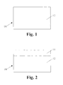
- FIG. 1 is a front view showing an assembly of a sheathing panel having the vapor, water and ice barrier placed thereon;
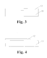
- FIG. 2 is a front view showing the assembly of the sheathing panel having the vapor, water and ice barrier placed thereon in an alternative embodiment of the invention
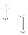
- FIG. 3 is a side view showing the assembly of the sheathing panel having the vapor, water and ice barrier placed thereon according to FIG. 1 ;
- FIG. 4 is a side view showing the assembly of the sheathing panel having the vapor, water and ice barrier placed thereon according to FIG. 2 ;
- FIG. 5 is a side view of the sheathing panel without the vapor, water and ice barrier placed thereon;
- FIG. 6 is a side view of the vapor, water and ice barrier.
- FIGS. 1-4 show two different embodiments of the present invention comprising a sheathing panel 11 having a vapor, water and ice layer 12 attached thereto.
- the vapor, water and ice layer 12 precludes vapor penetration and ice or water damage to the structure.
- the sheathing panel 11 is 4′ in width by 8′ in length having a thickness of 1 ⁇ 2′′ to 3 ⁇ 4′′.
- the dimensions of the sheathing panel 11 are not limiting, and the invention can be practiced with different size sheathing panels 11 .
- the vapor, water and ice layer 12 is supplied in rolls having different widths and having a thickness of approximately 0.040′′.
- the dimensions of the vapor, water and ice layer 12 are not limiting, and the invention can be practiced with different size vapor, water and ice layers 12 .
- FIGS. 1 and 3 show a first embodiment of the invention.
- the sheathing panel 11 has a first face 13 and a second face 14 as shown in FIG. 5 .
- the sheathing panel 11 is positioned so that the first face 13 or second face 14 is accessible.
- the vapor, water and ice layer 12 has a first side 15 and a second side 16 as shown in FIG. 6 .
- the second side 16 has a plastic film 17 covering an adhesive backing (not shown) on the second side 16 .
- the plastic film 17 is removed or peeled off of the vapor, water and ice layer 12 , thereby exposing the adhesive backing.
- the vapor, water and ice layer 12 is applied to either the first face 13 or the second face 14 of the sheathing panel 11 so that the adhesive backing contacts and adheres to the first face 13 or second face 14 of the sheathing panel 11 .
- the sheathing panel 11 has a pre-applied layer of adhesive on the first face 13 or the second face 14 , and the vapor, water and ice layer 12 does not have any adhesive backing.
- the sheathing panel 11 is positioned so that the first face 13 or second face 14 having the pre-applied adhesive is accessible.
- the first side 15 or the second side 16 of the vapor, water and ice layer 12 is placed onto the first face 13 or second face 14 having the pre-applied adhesive so that the adhesive contacts and adheres to the first side 15 or second side 16 of the vapor, water and ice layer 12 .
- the adhesive on the sheathing panel 11 may or may not be covered with a plastic or other similar strip (not shown). This strip protects the adhesive during shipping and handling. If a strip is covering the adhesive, it is obvious that the strip should be removed before assembling the vapor, water and ice layer 12 thereto. In another embodiment, both the sheathing panel 11 and the vapor, water and ice layer 12 have the pre-applied adhesive layer.
- the sheathing panel 11 and the vapor, water and ice layer 12 do not have the pre-applied adhesive layer. Rather, adhesive is applied during assembly of the sheathing panel 11 and the vapor, water and ice layer 12 .
- the vapor, water and ice layer 12 substantially covers the entire first face 13 or the entire second face 14 of the sheathing panel 11 .
- the coverage of the first face 13 or the second face 14 of the sheathing panel 11 is not limiting and can be adjusted according to the purpose of use.
- the vapor, water and ice layer 12 is applied to the first face 13 or second face 14 of the sheathing panel 11 as described in any one of the methods above, except the vapor, water and ice layer 12 covers three-fourths of the width of the first face 13 or the second face 14 of the sheathing panel 11 .
- the sheathing panel 11 will be 4 feet in width and the vapor, water and ice layer 12 will be three feet in width; hence, three-fourths of the width of the sheathing panel 11 is covered by the vapor, water and ice layer 12 .
- the coverage of the first face 13 or the second face 14 of the sheathing panel 11 with the vapor, water and ice layer 12 is not limiting and can be adjusted according to the purpose of use.
- the combination of the vapor, water and ice layer 12 and the sheathing panel 12 form an assembly 18 , 19 .
- the assembly 18 , 19 is transported to the roof and secured thereto. In most cases, the assembly 18 , 19 is nailed to the roof rafters. The nails penetrate the vapor, water ice layer 12 .
- the vapor, water and ice layer 12 is permeable and seals to the nail precluding seepage of vapor, water or ice.
- the eaves of the roof should be protected with the vapor, water and ice layer 12 .
- the assembly 18 , 19 will be secured to the areas above the eves.
- seam tape (not shown) is placed over the areas where the assemblies 18 , 19 abut each other from one of the assemblies 18 , 19 to the abutting assembly 18 , 19 .
- the seam tape is made of vapor, water and ice resistant material just as the material for the vapor, water and ice layer 12 .
- the seam tape is positioned over a gap between the abutting assemblies 18 , 19 and overlaps each of the assemblies 18 , 19 .
- the seam tape can be pre-applied to one of the abutting assemblies 18 , 19 so that when the assemblies 18 , 19 are secured to the rafters of the roof, the seam tape only need be pressed onto the assembly 18 , 19 not having the seam tape pre-attached thereto.
- the seam tape precludes vapor, water and ice from the area between the abutting assemblies 18 , 19 .
- the assembly 18 , 19 eliminates the efforts of carrying a roll of the vapor, water and ice layer 12 to the roof, unrolling the roll on the roof, peeling the plastic film 17 from the vapor, water and ice layer 12 while standing on the roof and properly placing the vapor, water and ice layer 12 on the sheathing panels 11 of the roof.
- the invention includes the process of pre-installing the vapor, water and ice layer 12 to the first face 13 or the second face 14 of the sheathing panel 11 before the sheathing panel 11 is assembled onto the rafters of a roof, comprising the steps of positioning the first face 13 or the second face 14 of the sheathing panel 11 in an upright or accessible position, peeling the plastic film 17 from the vapor, water and ice layer 12 , thereby exposing the adhesive surface on the second side 16 of the vapor, water and ice layer 12 , applying the adhesive surface of the vapor, and water and ice layer 12 onto the first face 13 or the second face 14 of the sheathing panel 11 .
- the assembly 18 , 19 is transported to the roof, and the assembly 18 , 19 is attached to the rafters of the roof. In most cases, the assembly 18 , 19 is nailed to the roof rafters. The nails penetrate the vapor, water ice layer 12 . The vapor, water and ice layer 12 is permeable and seals to the nail precluding seepage of vapor, water or ice. As an option, the seam tape is placed over the areas where the assemblies 18 , 19 abut each other from one of the assemblies 18 , 19 to the abutting assembly 18 , 19 to preclude vapor, water and ice from the area between the abutting assemblies 18 , 19 .
- the seam tape is positioned over a gap between the abutting assemblies 18 , 19 and overlaps each of the assemblies 18 , 19 .
- the adhesive is pre-applied or applied during the assembly to the sheathing panel 11 , the vapor, water and ice layer 12 or both.
- the vapor, water and ice layer 12 is sprayed onto the sheathing panel 11 .
- the adhesive is not required.
- the seam tape is placed over the areas where the assemblies 18 , 19 abut each other from one of the assemblies 18 , 19 to the abutting assembly 18 , 19 to preclude vapor, water and ice from the area between the abutting assemblies 18 , 19 .
- the seam tape is positioned over a gap between the abutting assemblies 18 , 19 and overlaps each of the assemblies 18 , 19 .
- the vapor, water and ice layer 12 is applied to the sheathing panel 11 by dipping the sheathing panel 11 into a dip tank (not shown) containing the vapor, water and ice layer 12 in a liquid form.
- the adhesive is not required.
- the seam tape is placed over the areas where the assemblies 18 , 19 abut each other from one of the assemblies 18 , 19 to the abutting assembly 18 , 19 to preclude vapor, water and ice from the area between the abutting assemblies 18 , 19 .
- the seam tape is positioned over a gap between the abutting assemblies 18 , 19 and overlaps each of the assemblies 18 , 19 .
Abstract
A process of pre-applying a vapor, water and ice layer to a sheathing panel before the sheathing panel is assembled onto rafters of a roof is disclosed, comprising the steps of positioning a face of the sheathing panel for accessibility, removing a plastic film from the vapor, water and ice layer, thereby exposing an adhesive surface of the vapor, water and ice layer, joining the adhesive surface of the vapor, and water and ice layer to the face of the sheathing panel to form an assembly, thereafter, transporting the assembly to the roof, and securing the assembly to the rafters of the roof. An article of manufacture for reducing water and ice damage caused by an ice dam on a roof is disclosed, wherein the article of manufacture is pre-assembled prior to assembly to rafters of the roof, comprising a sheathing panel for assembling on the rafters of the roof having a first face and a second face, a vapor, water and ice layer having a first side and a second side, the second side having a plastic film covering an adhesive backing, means for removing the plastic film to expose the adhesive backing and means for assembling the vapor, water and ice layer to the sheathing panel, wherein the second side of the vapor, water and ice layer having the adhesive backing is placed onto the first face of sheathing panel before assembly of the sheathing panel to the rafters of the roof.
Description
- This application is a continuation of U.S. patent application Ser. No. 10/993,018 filed on Nov. 19, 2004 which is a divisional of and claims priority to U.S. patent application Ser. No. 10/037,632 filed Jan. 3, 2002.
- Not Applicable.
- Not Applicable.
- This invention relates generally to a sealed roof and more particularly to a method and article of manufacture for sealing a roof against vapor penetration, water leakage and ice damage.
- Many structures are damaged due to the build-up of ice or ice dams on their roofs during the winter months. For example, snow may accumulate on a roof and create an insulating layer between the outside environment and the roof. As residual heat escapes from the structure through the roof, the snow in the proximity of the roof begins to melt and the water runs down the roof under the snow as is the case in a rain storm. Normally, water exits the roof by passing over the eaves and off the roof or down a drainage system.
- Under certain cold conditions, the temperature of the roof areas above the eaves is below the freezing point, because they are not heated by the residual heat escaping from the structure. As a result, the water freezes as it contacts the cold roof area over the eaves. This causes ice to build up on the roof over the eaves, which forms a barricade or an ice dam. The water behind the ice dam and on the roof remains in a liquid form due to the residual heat escaping from the structure. Pitched shingled, shaked, tiled or slated roofs are constructed by overlapping shingles, shakes, tiles or slates (hereinafter collectively “shingles”); therefore, the standing water behind the ice dam may seep under the shingles and into the structure causing water damage.
- Most overlaid shingled roofs are not designed to seal against the standing water caused by ice dams. They are designed, through their overlaid placement, to seal against water running off the roof. When water stands on a pitched shingled roof, the water seeps under the shingles, through the sheathing and into the structure. Water damage is aesthetically unappealing, very costly to repair and can lead to the proliferation of mold, which has been known to cause health problems in humans.
- There are construction devices and methods used to protect structures from damage caused by water standing on their pitched shingled roofs due to ice dams. These devices and methods include placing low friction roof elements on the eaves, so the ice slides off the roof. Some systems use electric heaters placed upon the eaves to melt the ice dams or to keep them from forming. Another way to prevent water damage to the structure is by placing a waterproof membrane on the sheathing and under the shingles. In the event an ice dam occurs, the membrane seals the structure from the standing water, preventing water from contacting the sheathing.
- The following is a simplistic overview of the process for assembling a roof. Sheathing is secured to the rafters or roof frame. In most cases, a 4 feet in width by 8 feet in length piece of plywood having a thickness of ½″ to ¾″ is used as sheathing. A vapor barrier is placed on the sheathing of the roof. The vapor barrier commonly used is 15#-30# tar paper that is available in 3′ rolls. The vapor barrier is not effective in precluding leakage caused by ice dams. Based on this, quality builders will assemble a vapor-, water- and ice-resistant layer along the eaves and valleys of the roofs to preclude, inter alia, water leakage due to ice dams. The vapor-, water- and ice-resistant layer is placed along the edges of the roof or eaves in lieu of the vapor barrier or tar paper. In addition, the vapor-, water- and ice-resistant layer is placed in other areas of the roof prone to water leakage, such as the valleys, in lieu of the vapor barrier or tar paper. The vapor- and water-resistant layer usually comes in 3′ rolls, and the industry standard is a 0.040″ thick vapor-, water- and ice-resistant layer. There are various manufacturers of and names used for the vapor-, water- and ice-resistant layer. For example, GAF Corporation located at 1361 Alps Road, Wayne, N.J. 07470 is the owner of the Weather Watch® trademark registration for roofing membranes, and Owens-Corning Fiberglas Technology Inc. located at 7734 West 59th Street, Summit, Ill. 60501 is the owner of the WeatherGuard® trademark registration for similar goods. It is important to note that there are other manufacturers of and products that are vapor-, water- and ice-resistant for precluding water leakage caused by ice dams. After placing the tar paper and vapor-, water- and ice-resistant layer in the appropriate locations on the roof, shingles are placed thereon in an overlapping construction from the lower portion of the pitched roof to the peak of the pitched roof as previously explained. For example, the first column of shingles placed along the lowest portion of the pitched roof is overlapped by the second column of shingles. This overlap construction continues upward until the peak of the roof is reached.
- Turning now to the vapor-, water- and ice-resistant layer, it is generally supplied in 3′ wide rolls having an adhesive backing that adheres to the sheathing. The adhesive backing is temporarily protected with a plastic film, which is removed prior to assembly to the sheathing panel. In most cases, the vapor-, water- and ice-resistant layer is placed along the eaves, which are subjected to ice dams, and other problematic areas prone to leakage. These rolls are heavy and difficult to manipulate and carry up to the roof. Once on the roof, the roll is unrolled along the length of the roof that is to receive the vapor-, water- and ice-resistant layer. This process is very difficult to perform on a pitched roof and can be dangerous. The adhesive backing is exposed by peeling off the plastic film covering the adhesive on the back of the vapor-, water- and ice-resistant layer. The vapor-, water- and ice-resistant layer is placed on the roof and secured thereto. This process is very difficult to perform on a pitched roof and can be dangerous. In hot weather, the adhesive backing is very tacky and difficult to handle. Improper placement of the vapor-, water- and ice-resistant layer results in, inter alia, kinks, seams and non-uniform coverage. In cold weather, the adhesive backing does not stick well to the sheathing and is difficult to align and secure to the sheathing. In windy conditions, handling the vapor-, water- and ice-resistant layer is problematic. Walking along the edges of a roof is dangerous without these adverse conditions. Moreover, combine any of these conditions and the placement of the vapor-, water- and ice-resistant layer is extremely difficult and hazardous.
- The present invention is directed to overcoming one or more of the problems or disadvantages set forth above.
- An aspect of the present invention is to provide an article of manufacture for overcoming one or more of the problems and disadvantages set forth above.
- It is an aspect of this invention to provide a method for waterproofing roofs.
- In another aspect of the invention, there is a method of assembling a layer of vapor, water and ice resistant material onto a sheathing panel to form an ice dam for use in roof construction before the sheathing panel is secured onto roof rafters, the vapor, water and ice resistant material having on one side thereof an adhesive surface covered with a plastic film, comprising the steps of positioning a face of the sheathing panel in a generally horizontal plane for accessibility in a controlled atmosphere, removing the plastic film from the vapor, water and ice layer, thereby exposing the adhesive surface of the vapor, water and ice layer, positioning a corner of the vapor, water and ice layer at a corner of the sheathing panel and aligning their longitudinal edges and pressing the adhesive surface of the vapor, and water and ice layer to the face of the sheathing panel to form an assembly, thereby forming an ice dam for use in roof construction.
- Another aspect of this invention is to provide an article of manufacture for waterproofing roofs.
- In another aspect of the invention, there is a pre-assembled article of manufacture providing a vapor, water and ice barrier for roofs.
- In yet another aspect of the invention, there is provided a method for pre-installing a vapor, water and ice barrier prior to placement on the roof.
- In still yet another aspect of the invention, there is provided a method for pre-applying a vapor, water and ice barrier on sheathing panels for roofs.
- In still another aspect of the invention, there is provided a sheathing panel having a pre-applied vapor, water and ice barrier thereon.
- These, and other aspects and advantages of the present invention, will become apparent as the invention becomes better understood from the Detailed Description, appended claims and the accompanying drawings.
- Reference is now made to the drawings, which illustrate the best known mode for carrying out the invention, and wherein similar reference characters indicate the same parts throughout the several views.
-
FIG. 1 is a front view showing an assembly of a sheathing panel having the vapor, water and ice barrier placed thereon; -
FIG. 2 is a front view showing the assembly of the sheathing panel having the vapor, water and ice barrier placed thereon in an alternative embodiment of the invention; -
FIG. 3 is a side view showing the assembly of the sheathing panel having the vapor, water and ice barrier placed thereon according toFIG. 1 ; -
FIG. 4 is a side view showing the assembly of the sheathing panel having the vapor, water and ice barrier placed thereon according toFIG. 2 ; -
FIG. 5 is a side view of the sheathing panel without the vapor, water and ice barrier placed thereon; and -
FIG. 6 is a side view of the vapor, water and ice barrier. -
FIGS. 1-4 show two different embodiments of the present invention comprising asheathing panel 11 having a vapor, water andice layer 12 attached thereto. The vapor, water andice layer 12 precludes vapor penetration and ice or water damage to the structure. In most cases, thesheathing panel 11 is 4′ in width by 8′ in length having a thickness of ½″ to ¾″. However, the dimensions of thesheathing panel 11 are not limiting, and the invention can be practiced with differentsize sheathing panels 11. The vapor, water andice layer 12 is supplied in rolls having different widths and having a thickness of approximately 0.040″. However, the dimensions of the vapor, water andice layer 12 are not limiting, and the invention can be practiced with different size vapor, water and ice layers 12. -
FIGS. 1 and 3 show a first embodiment of the invention. Thesheathing panel 11 has afirst face 13 and asecond face 14 as shown inFIG. 5 . Thesheathing panel 11 is positioned so that thefirst face 13 orsecond face 14 is accessible. The vapor, water andice layer 12 has afirst side 15 and asecond side 16 as shown inFIG. 6 . In the preferred embodiment, thesecond side 16 has aplastic film 17 covering an adhesive backing (not shown) on thesecond side 16. Theplastic film 17 is removed or peeled off of the vapor, water andice layer 12, thereby exposing the adhesive backing. The vapor, water andice layer 12 is applied to either thefirst face 13 or thesecond face 14 of thesheathing panel 11 so that the adhesive backing contacts and adheres to thefirst face 13 orsecond face 14 of thesheathing panel 11. In alternative embodiments, thesheathing panel 11 has a pre-applied layer of adhesive on thefirst face 13 or thesecond face 14, and the vapor, water andice layer 12 does not have any adhesive backing. In this embodiment, thesheathing panel 11 is positioned so that thefirst face 13 orsecond face 14 having the pre-applied adhesive is accessible. Thefirst side 15 or thesecond side 16 of the vapor, water andice layer 12 is placed onto thefirst face 13 orsecond face 14 having the pre-applied adhesive so that the adhesive contacts and adheres to thefirst side 15 orsecond side 16 of the vapor, water andice layer 12. The adhesive on thesheathing panel 11 may or may not be covered with a plastic or other similar strip (not shown). This strip protects the adhesive during shipping and handling. If a strip is covering the adhesive, it is obvious that the strip should be removed before assembling the vapor, water andice layer 12 thereto. In another embodiment, both thesheathing panel 11 and the vapor, water andice layer 12 have the pre-applied adhesive layer. In anther embodiment, thesheathing panel 11 and the vapor, water andice layer 12 do not have the pre-applied adhesive layer. Rather, adhesive is applied during assembly of thesheathing panel 11 and the vapor, water andice layer 12. In the embodiment shown inFIGS. 1 and 3 , the vapor, water andice layer 12 substantially covers the entirefirst face 13 or the entiresecond face 14 of thesheathing panel 11. However, it is important to note that the coverage of thefirst face 13 or thesecond face 14 of thesheathing panel 11 is not limiting and can be adjusted according to the purpose of use. - In a second embodiment of the invention as shown in
FIGS. 2 and 4 , the vapor, water andice layer 12 is applied to thefirst face 13 orsecond face 14 of thesheathing panel 11 as described in any one of the methods above, except the vapor, water andice layer 12 covers three-fourths of the width of thefirst face 13 or thesecond face 14 of thesheathing panel 11. In one example, thesheathing panel 11 will be 4 feet in width and the vapor, water andice layer 12 will be three feet in width; hence, three-fourths of the width of thesheathing panel 11 is covered by the vapor, water andice layer 12. The coverage of thefirst face 13 or thesecond face 14 of thesheathing panel 11 with the vapor, water andice layer 12 is not limiting and can be adjusted according to the purpose of use. - The combination of the vapor, water and
ice layer 12 and thesheathing panel 12 form anassembly assembly assembly water ice layer 12. The vapor, water andice layer 12 is permeable and seals to the nail precluding seepage of vapor, water or ice. For example, the eaves of the roof should be protected with the vapor, water andice layer 12. Theassembly assemblies assemblies assembly ice layer 12. The seam tape is positioned over a gap between the abuttingassemblies assemblies assemblies assemblies assembly assemblies assembly ice layer 12 to the roof, unrolling the roll on the roof, peeling theplastic film 17 from the vapor, water andice layer 12 while standing on the roof and properly placing the vapor, water andice layer 12 on thesheathing panels 11 of the roof. - In the preferred embodiment, the invention includes the process of pre-installing the vapor, water and
ice layer 12 to thefirst face 13 or thesecond face 14 of thesheathing panel 11 before thesheathing panel 11 is assembled onto the rafters of a roof, comprising the steps of positioning thefirst face 13 or thesecond face 14 of thesheathing panel 11 in an upright or accessible position, peeling theplastic film 17 from the vapor, water andice layer 12, thereby exposing the adhesive surface on thesecond side 16 of the vapor, water andice layer 12, applying the adhesive surface of the vapor, and water andice layer 12 onto thefirst face 13 or thesecond face 14 of thesheathing panel 11. Thereafter, theassembly assembly assembly water ice layer 12. The vapor, water andice layer 12 is permeable and seals to the nail precluding seepage of vapor, water or ice. As an option, the seam tape is placed over the areas where theassemblies assemblies assembly assemblies assemblies assemblies sheathing panel 11, the vapor, water andice layer 12 or both. - In an alternative embodiment, the vapor, water and
ice layer 12 is sprayed onto thesheathing panel 11. In this embodiment, the adhesive is not required. After installation of theassembly assemblies assemblies assembly assemblies assemblies assemblies - In an alternative embodiment, the vapor, water and
ice layer 12 is applied to thesheathing panel 11 by dipping thesheathing panel 11 into a dip tank (not shown) containing the vapor, water andice layer 12 in a liquid form. In this embodiment, the adhesive is not required. After installation of theassembly assemblies assemblies assembly assemblies assemblies assemblies - Other objects, features and advantages will be apparent to those skilled in the art. While preferred embodiments of the present invention have been illustrated and described, this has been by way of illustration and the invention should not be limited except as required by the scope of the appended claims.
Claims (13)
1. A roofing panel for a roof having a plurality of roof rafters, comprising:
a sheathing panel having a face;
a vapor, water, or ice resistant layer to said face;
said sheathing panel and
said resistant layer being fixed together before being attached to the roof rafters, thereby comprising a modular roof panel.
2. The roof panel according to claim 1 , wherein said vapor, water, and ice resistant layer is attached to said sheathing panel with an adhesive.
3. The roof panel according to claim 1 , wherein said vapor, water, and ice resistant layer is sprayed onto said sheathing panel.
4. The roof panel according to claim 1 , wherein said vapor, water, and ice resistant layer is formed on said sheathing panel by dipping said sheathing panel into a dip tank containing said vapor, water, and ice resistant layer.
5. The roof panel according to claim 1 , wherein said vapor, water, and ice resistant layer covers at least three-fourths of said sheathing panel.
6. The roof panel according to claim 1 , wherein said sheathing panel is nailed to said at least one of the plurality of roof rafters.
7. The roofing panel of claim 1 wherein said resistant layer seals around nails used to secure said panel to the rafters.
8. The roofing panel of claim 1 wherein said roofing panel is plywood.
9. The roofing panel of claim 1 wherein said panel is dimensioned to be adjacent to an eave of a roof.
10. The roofing panel of claim 1 having four edges, said resistant layer being further attached to at least one of said edges.
11. The roofing panel of claim 1 wherein said resistant layer extends beyond an edge of said sheathing panel.
12. The roofing panel of claim 1 further comprising tape for sealing a joint between said roofing panel and an adjacent panel in assembly.
13. The roofing panel of claim 1 wherein said resistant layer is underneath said sheathing panel.
Priority Applications (1)
| Application Number | Priority Date | Filing Date | Title |
|---|---|---|---|
| US11/959,011 US20080098667A1 (en) | 2002-01-03 | 2007-12-18 | Method and article of manufacture for sealing a roof |
Applications Claiming Priority (3)
| Application Number | Priority Date | Filing Date | Title |
|---|---|---|---|
| US3763202A | 2002-01-03 | 2002-01-03 | |
| US10/993,018 US7310921B2 (en) | 2002-01-03 | 2004-11-19 | Method and article of manufacture for sealing a roof |
| US11/959,011 US20080098667A1 (en) | 2002-01-03 | 2007-12-18 | Method and article of manufacture for sealing a roof |
Related Parent Applications (1)
| Application Number | Title | Priority Date | Filing Date |
|---|---|---|---|
| US10/993,018 Continuation US7310921B2 (en) | 2002-01-03 | 2004-11-19 | Method and article of manufacture for sealing a roof |
Publications (1)
| Publication Number | Publication Date |
|---|---|
| US20080098667A1 true US20080098667A1 (en) | 2008-05-01 |
Family
ID=34572313
Family Applications (2)
| Application Number | Title | Priority Date | Filing Date |
|---|---|---|---|
| US10/993,018 Expired - Fee Related US7310921B2 (en) | 2002-01-03 | 2004-11-19 | Method and article of manufacture for sealing a roof |
| US11/959,011 Abandoned US20080098667A1 (en) | 2002-01-03 | 2007-12-18 | Method and article of manufacture for sealing a roof |
Family Applications Before (1)
| Application Number | Title | Priority Date | Filing Date |
|---|---|---|---|
| US10/993,018 Expired - Fee Related US7310921B2 (en) | 2002-01-03 | 2004-11-19 | Method and article of manufacture for sealing a roof |
Country Status (1)
| Country | Link |
|---|---|
| US (2) | US7310921B2 (en) |
Cited By (3)
| Publication number | Priority date | Publication date | Assignee | Title |
|---|---|---|---|---|
| US20130263552A1 (en) * | 2012-04-05 | 2013-10-10 | Carlisle Intangible Company | Single ply roofing membranes with multifunctional biodegradable release liner |
| US9234355B2 (en) | 2012-05-31 | 2016-01-12 | Huber Engineered Woods Llc | Insulated sheathing panel and methods for use and manufacture thereof |
| US11536028B2 (en) | 2004-02-23 | 2022-12-27 | Huber Engineered Woods Llc | Panel for sheathing system and method |
Families Citing this family (9)
| Publication number | Priority date | Publication date | Assignee | Title |
|---|---|---|---|---|
| US7310921B2 (en) * | 2002-01-03 | 2007-12-25 | Williams Douglas C | Method and article of manufacture for sealing a roof |
| US8621799B2 (en) * | 2006-03-01 | 2014-01-07 | Rovshan Sade | External wall and roof systems |
| CN103732522B (en) * | 2011-08-10 | 2016-08-17 | 因温特奥股份公司 | Fire lift |
| US20130084419A1 (en) * | 2011-10-03 | 2013-04-04 | Textile Rubber And Chemical Company, Inc. | Moisture/vapor barrier and method of making and using same |
| USD719596S1 (en) | 2012-12-20 | 2014-12-16 | Sfs Intec Holding Ag | Induction apparatus |
| US10138919B2 (en) | 2015-12-10 | 2018-11-27 | Thomas R. Mathieson | Waterproof nail and screw with enlarged head and protective gasket |
| US10072418B2 (en) | 2015-12-10 | 2018-09-11 | Thomas R. Mathieson | Integral nail/disk structure for eliminating exposed roof nails |
| US10190316B2 (en) * | 2015-12-10 | 2019-01-29 | Thomas R. Mathieson | One-piece and two-piece shingle repair patch |
| US9631383B1 (en) * | 2015-12-10 | 2017-04-25 | Thomas R. Mathieson | Shingle patch for hail damage repair of asphalt shingles and an integral nail/disk structure for eliminating exposed roof nails |
Citations (30)
| Publication number | Priority date | Publication date | Assignee | Title |
|---|---|---|---|---|
| US3466222A (en) * | 1967-07-26 | 1969-09-09 | Lexsuco Inc | Fire retardant insulative structure and roof deck construction comprising the same |
| US3900102A (en) * | 1970-01-14 | 1975-08-19 | Grace W R & Co | Waterproofing means and method |
| US4063395A (en) * | 1974-05-10 | 1977-12-20 | Grefco, Inc. | Twin membrane, self sealing, mechanically fastened insulated roof deck system |
| US4073997A (en) * | 1974-12-06 | 1978-02-14 | Owens-Corning Fiberglas Corporation | Composite panel |
| US4160346A (en) * | 1976-05-11 | 1979-07-10 | Global Coatings Limited | Roof coating composition and construction |
| US4194335A (en) * | 1977-12-08 | 1980-03-25 | Diamond John N | Single sheathing roof panel |
| US4282697A (en) * | 1978-04-27 | 1981-08-11 | Dynamit Nobel Aktiengesellschaft | Insulating panel for roof coverings |
| US4450663A (en) * | 1981-06-15 | 1984-05-29 | Watkins Norman C | Insulative roof structure |
| US4601935A (en) * | 1985-05-06 | 1986-07-22 | Gencorp Inc. | EPDM laminate |
| US4757652A (en) * | 1987-08-05 | 1988-07-19 | Tarmac Roofing Systems, Inc. | Roofing product |
| US4775567A (en) * | 1986-10-24 | 1988-10-04 | Hyload Corporation | Waterproofing laminate |
| US4936070A (en) * | 1989-02-22 | 1990-06-26 | Michaud Robert E | Roof covering panel |
| US4965119A (en) * | 1986-05-23 | 1990-10-23 | The Kendall Company | Tapered roofing tape |
| US4992315A (en) * | 1989-11-13 | 1991-02-12 | Gaf Buildinhg Materials Corp. | Roofing membrane and method |
| US5096759A (en) * | 1988-07-27 | 1992-03-17 | Mineral Fiber Manufacturing Corporation | Laminated roofing sheet |
| US5099627A (en) * | 1990-09-28 | 1992-03-31 | Benjamin Obdyke Incorporated | Ventilated roof construction and method |
| US5598673A (en) * | 1994-01-18 | 1997-02-04 | Atkins; Mark R. | Masonry cavity wall air space and weeps obstruction prevention system |
| US5766721A (en) * | 1995-10-24 | 1998-06-16 | Bussey, Jr.; Harry | Insulation barrier |
| US5843552A (en) * | 1992-02-18 | 1998-12-01 | Bridgestone/Firestone, Inc. | Multicomponent self-sealing seam tape |
| US6023906A (en) * | 1998-02-27 | 2000-02-15 | Folkersen; Jonny | Method for sealing pitched roofs |
| US6209283B1 (en) * | 1998-02-27 | 2001-04-03 | Jonny Folkersen | Sealed roof and method for sealing a roof |
| US6235365B1 (en) * | 1998-12-18 | 2001-05-22 | W. R. Grace & Co.-Conn. | Waterproofing membrane having release sheet cutting system |
| US6296912B1 (en) * | 1998-06-29 | 2001-10-02 | Northern Elastomeric, Inc. | Roofing material with fibrous mat |
| US20030054127A1 (en) * | 1998-02-18 | 2003-03-20 | Raphael Heifetz | Sealing sheet assembly for construction surfaces and methods of making and applying same |
| US6769215B1 (en) * | 2002-08-19 | 2004-08-03 | Siplast, Inc. | System and method for enhancing the bond of roofing membrane to lightweight insulating concrete |
| US6804922B1 (en) * | 1998-06-03 | 2004-10-19 | Construction Research & Technology Gmbh | Integral composite building material and uses therefor |
| US20040226247A1 (en) * | 2003-05-13 | 2004-11-18 | Byrd Bobby Joe | Building panel with impermeable surface layer |
| US20060141191A1 (en) * | 2003-01-30 | 2006-06-29 | Jyoti Seth | Moisture barrier membrane with tearable release liner composite |
| US7310921B2 (en) * | 2002-01-03 | 2007-12-25 | Williams Douglas C | Method and article of manufacture for sealing a roof |
| US7658040B2 (en) * | 2004-02-23 | 2010-02-09 | Huber Engineered Woods Llc | Panel for sheathing system and method |
Family Cites Families (7)
| Publication number | Priority date | Publication date | Assignee | Title |
|---|---|---|---|---|
| US2044782A (en) * | 1933-04-13 | 1936-06-23 | Bakelite Building Prod Co Inc | Roofing element |
| US2144168A (en) * | 1937-10-11 | 1939-01-17 | Sherriff Goslin Co | Roof construction and method of laying roll roofing |
| US2226239A (en) * | 1938-12-30 | 1940-12-24 | Elmendorf Armin | Shingle roof construction |
| US2246514A (en) * | 1940-06-14 | 1941-06-24 | Hardy James Harris | Method for forming building surfaces |
| US4172830A (en) * | 1977-11-14 | 1979-10-30 | W. R. Grace & Co. | Waterproofing structure and method of using same |
| US4825616A (en) * | 1988-04-21 | 1989-05-02 | Gaf Corporation | Roofing shingle |
| US6701685B2 (en) * | 2001-03-01 | 2004-03-09 | Johns Manville International, Inc. | Waterproof roofing barrier |
-
2004
- 2004-11-19 US US10/993,018 patent/US7310921B2/en not_active Expired - Fee Related
-
2007
- 2007-12-18 US US11/959,011 patent/US20080098667A1/en not_active Abandoned
Patent Citations (31)
| Publication number | Priority date | Publication date | Assignee | Title |
|---|---|---|---|---|
| US3466222A (en) * | 1967-07-26 | 1969-09-09 | Lexsuco Inc | Fire retardant insulative structure and roof deck construction comprising the same |
| US3900102A (en) * | 1970-01-14 | 1975-08-19 | Grace W R & Co | Waterproofing means and method |
| US4063395A (en) * | 1974-05-10 | 1977-12-20 | Grefco, Inc. | Twin membrane, self sealing, mechanically fastened insulated roof deck system |
| US4073997A (en) * | 1974-12-06 | 1978-02-14 | Owens-Corning Fiberglas Corporation | Composite panel |
| US4160346A (en) * | 1976-05-11 | 1979-07-10 | Global Coatings Limited | Roof coating composition and construction |
| US4194335A (en) * | 1977-12-08 | 1980-03-25 | Diamond John N | Single sheathing roof panel |
| US4282697A (en) * | 1978-04-27 | 1981-08-11 | Dynamit Nobel Aktiengesellschaft | Insulating panel for roof coverings |
| US4450663A (en) * | 1981-06-15 | 1984-05-29 | Watkins Norman C | Insulative roof structure |
| US4601935A (en) * | 1985-05-06 | 1986-07-22 | Gencorp Inc. | EPDM laminate |
| US4965119A (en) * | 1986-05-23 | 1990-10-23 | The Kendall Company | Tapered roofing tape |
| US4775567A (en) * | 1986-10-24 | 1988-10-04 | Hyload Corporation | Waterproofing laminate |
| US4757652A (en) * | 1987-08-05 | 1988-07-19 | Tarmac Roofing Systems, Inc. | Roofing product |
| US5096759A (en) * | 1988-07-27 | 1992-03-17 | Mineral Fiber Manufacturing Corporation | Laminated roofing sheet |
| US4936070A (en) * | 1989-02-22 | 1990-06-26 | Michaud Robert E | Roof covering panel |
| US4992315A (en) * | 1989-11-13 | 1991-02-12 | Gaf Buildinhg Materials Corp. | Roofing membrane and method |
| US5099627A (en) * | 1990-09-28 | 1992-03-31 | Benjamin Obdyke Incorporated | Ventilated roof construction and method |
| US5843552A (en) * | 1992-02-18 | 1998-12-01 | Bridgestone/Firestone, Inc. | Multicomponent self-sealing seam tape |
| US5598673A (en) * | 1994-01-18 | 1997-02-04 | Atkins; Mark R. | Masonry cavity wall air space and weeps obstruction prevention system |
| US5766721A (en) * | 1995-10-24 | 1998-06-16 | Bussey, Jr.; Harry | Insulation barrier |
| US20030054127A1 (en) * | 1998-02-18 | 2003-03-20 | Raphael Heifetz | Sealing sheet assembly for construction surfaces and methods of making and applying same |
| US6023906A (en) * | 1998-02-27 | 2000-02-15 | Folkersen; Jonny | Method for sealing pitched roofs |
| US6209283B1 (en) * | 1998-02-27 | 2001-04-03 | Jonny Folkersen | Sealed roof and method for sealing a roof |
| US20010010141A1 (en) * | 1998-02-27 | 2001-08-02 | Jonny Folkersen | Sealed roof and method for sealing a roof |
| US6804922B1 (en) * | 1998-06-03 | 2004-10-19 | Construction Research & Technology Gmbh | Integral composite building material and uses therefor |
| US6296912B1 (en) * | 1998-06-29 | 2001-10-02 | Northern Elastomeric, Inc. | Roofing material with fibrous mat |
| US6235365B1 (en) * | 1998-12-18 | 2001-05-22 | W. R. Grace & Co.-Conn. | Waterproofing membrane having release sheet cutting system |
| US7310921B2 (en) * | 2002-01-03 | 2007-12-25 | Williams Douglas C | Method and article of manufacture for sealing a roof |
| US6769215B1 (en) * | 2002-08-19 | 2004-08-03 | Siplast, Inc. | System and method for enhancing the bond of roofing membrane to lightweight insulating concrete |
| US20060141191A1 (en) * | 2003-01-30 | 2006-06-29 | Jyoti Seth | Moisture barrier membrane with tearable release liner composite |
| US20040226247A1 (en) * | 2003-05-13 | 2004-11-18 | Byrd Bobby Joe | Building panel with impermeable surface layer |
| US7658040B2 (en) * | 2004-02-23 | 2010-02-09 | Huber Engineered Woods Llc | Panel for sheathing system and method |
Cited By (6)
| Publication number | Priority date | Publication date | Assignee | Title |
|---|---|---|---|---|
| US11536028B2 (en) | 2004-02-23 | 2022-12-27 | Huber Engineered Woods Llc | Panel for sheathing system and method |
| US11697939B2 (en) | 2004-02-23 | 2023-07-11 | Huber Engineered Woods Llc | Panel for sheathing system and method |
| US20130263552A1 (en) * | 2012-04-05 | 2013-10-10 | Carlisle Intangible Company | Single ply roofing membranes with multifunctional biodegradable release liner |
| US8833037B2 (en) * | 2012-04-05 | 2014-09-16 | Carlisle Intangible Company | Single ply roofing membranes with multifunctional biodegradable release liner |
| US9234355B2 (en) | 2012-05-31 | 2016-01-12 | Huber Engineered Woods Llc | Insulated sheathing panel and methods for use and manufacture thereof |
| US11414865B2 (en) | 2012-05-31 | 2022-08-16 | Huber Engineered Woods Llc | Insulated sheathing panel |
Also Published As
| Publication number | Publication date |
|---|---|
| US20050102922A1 (en) | 2005-05-19 |
| US7310921B2 (en) | 2007-12-25 |
Similar Documents
| Publication | Publication Date | Title |
|---|---|---|
| US20080098667A1 (en) | Method and article of manufacture for sealing a roof | |
| US6701685B2 (en) | Waterproof roofing barrier | |
| CA1264913A (en) | Roofing system | |
| US6401424B2 (en) | Sealed roof and method for sealing a roof | |
| US11168484B2 (en) | Roof and wall cover system | |
| US5394672A (en) | Interlocking insulated roof panel system | |
| US4386981A (en) | Method of waterproofing roofs and the like | |
| US7685785B2 (en) | Roof underlayment | |
| US6023906A (en) | Method for sealing pitched roofs | |
| US20040226247A1 (en) | Building panel with impermeable surface layer | |
| US4016323A (en) | Method and construction of roof system | |
| FI64698B (en) | TAKTAECKNINGSFOERFARANDE | |
| US8397446B2 (en) | Composite roofing or other surfacing board, method of making and using and roof made thereby | |
| US20200347601A1 (en) | Water resistant roofing underlayment | |
| US8079191B2 (en) | Method and system for covering flat roofs | |
| US20180038109A1 (en) | Insulated modular roof system | |
| US20190161970A1 (en) | Sealed tabbed asphalt shingle system and method | |
| AU2008203409A1 (en) | Roof Cover System | |
| US11927017B2 (en) | Roofing system and method | |
| US11555318B2 (en) | Roof cover system improvement | |
| US20230117195A1 (en) | Ice and water shield with sealable drip edge pocket and associated methods | |
| WO2021207794A1 (en) | Roof cover system improvement | |
| US20060005496A1 (en) | Torchless self-adhesive roofing product and method | |
| JPS5923129Y2 (en) | roof | |
| CA2144362A1 (en) | Roofing shingle preform and methods of manufacturing and using the same |
Legal Events
| Date | Code | Title | Description |
|---|---|---|---|
| STCB | Information on status: application discontinuation |
Free format text: ABANDONED -- FAILURE TO RESPOND TO AN OFFICE ACTION |