US20080098612A1 - Roof Drying Apparatus - Google Patents
Roof Drying Apparatus Download PDFInfo
- Publication number
- US20080098612A1 US20080098612A1 US11/813,751 US81375106A US2008098612A1 US 20080098612 A1 US20080098612 A1 US 20080098612A1 US 81375106 A US81375106 A US 81375106A US 2008098612 A1 US2008098612 A1 US 2008098612A1
- Authority
- US
- United States
- Prior art keywords
- air
- blower
- engine
- housing
- outlet
- Prior art date
- Legal status (The legal status is an assumption and is not a legal conclusion. Google has not performed a legal analysis and makes no representation as to the accuracy of the status listed.)
- Abandoned
Links
Images

Classifications
-
- E—FIXED CONSTRUCTIONS
- E01—CONSTRUCTION OF ROADS, RAILWAYS, OR BRIDGES
- E01C—CONSTRUCTION OF, OR SURFACES FOR, ROADS, SPORTS GROUNDS, OR THE LIKE; MACHINES OR AUXILIARY TOOLS FOR CONSTRUCTION OR REPAIR
- E01C23/00—Auxiliary devices or arrangements for constructing, repairing, reconditioning, or taking-up road or like surfaces
- E01C23/14—Auxiliary devices or arrangements for constructing, repairing, reconditioning, or taking-up road or like surfaces for heating or drying foundation, paving, or materials thereon, e.g. paint
-
- E—FIXED CONSTRUCTIONS
- E01—CONSTRUCTION OF ROADS, RAILWAYS, OR BRIDGES
- E01H—STREET CLEANING; CLEANING OF PERMANENT WAYS; CLEANING BEACHES; DISPERSING OR PREVENTING FOG IN GENERAL CLEANING STREET OR RAILWAY FURNITURE OR TUNNEL WALLS
- E01H1/00—Removing undesirable matter from roads or like surfaces, with or without moistening of the surface
- E01H1/08—Pneumatically dislodging or taking-up undesirable matter or small objects; Drying by heat only or by streams of gas; Cleaning by projecting abrasive particles
- E01H1/0809—Loosening or dislodging by blowing ; Drying by means of gas streams
Definitions
- the present invention relates to roof drying apparatus, to a duct device for producing roof drying apparatus, and to a method of drying a roof using such apparatus.
- Air blower devices such as commonly available leafblowers, have been utilised to physically blow water off a structure/substrate. However, these devices only blow ambient temperature air, and thus do not rapidly dry out a structure/substrate.
- the present invention seeks to provide a solution to this problem.
- roof drying apparatus comprising: a housing having one or more air inlets and an air outlet; an internal combustion engine mounted in the housing; and a blower mechanism which is drivable by the engine for forcing air out of the air outlet of the housing, characterised in that an exhaust outlet of the engine is positioned to discharge exhaust gas in or onto an air flow path which extends from the or at least one of the air inlets to the air outlet so that, in use, at least a portion of the air outputted from the air outlet by the blower mechanism is pre-heated by the exhaust gas of the engine.
- a duct device for adapting an internal combustion engine handheld air blower device to form roof drying apparatus as claimed in any one of the preceding claims, the device comprising a tubular body having two openings, a first one of the openings being adapted for connection to an engine compartment exhaust outlet of a housing of the air blower device to direct exhaust gas into the duct device, and a second one of the openings being adapted for connection to a blower compartment air inlet of the housing of the air blower device, so that, in use, at least a portion of air which is outputted from a blower mechanism air outlet of the blower device is pre-heated by exhaust gas of the engine of the blower device being drawn from the engine compartment exhaust outlet along the duct device and through the blower compartment air inlet.
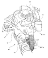
- FIG. 1 is a perspective view of one embodiment of roof drying apparatus, in accordance with the first aspect of the invention, having a duct device in accordance with the second aspect of the invention;
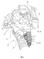
- FIG. 2 is a top plan view of the roof drying apparatus and duct device shown in FIG. 1 ;
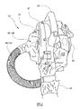
- FIG. 3 is a view from one side of the roof drying apparatus with the duct device and air discharge nozzle removed;
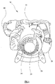
- FIG. 4 is a view from the other side of the roof drying apparatus shown in FIG. 3 ;
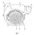
- FIG. 5 is a perspective view from the front of the roof drying apparatus shown in FIG. 3 .
- roof drying apparatus 10 which comprises a housing 12 having a handle or grip 14 with user operable controls 16 , feet or a stand 18 on the bottom of the housing 12 , a drive motor compartment 20 provided in one part of the housing 12 , and a blower compartment 22 provided in another part of the housing 12 .
- An internal combustion (i.c.) engine 24 is located in the drive motor compartment 20 of the housing 12 , and an ambient air inlet 26 of the roof drying apparatus 10 is formed in an outside wall of the housing 12 and adjacent to the i.c. engine 24 air intake (not shown).
- a fuel inlet 28 projects from the housing 12 for receiving fuel to run the i.c. engine 24 , and an exhaust outlet 30 of the i.c. engine 24 is positioned in or adjacent to an air outlet 32 of the drive motor compartment 20 (see FIG. 5 ).
- a blower mechanism 34 is provided in the blower compartment 22 of the housing 12 .
- the blower mechanism 34 comprises a blower wheel 36 which is mounted for rotation in a generally spiral shaped cavity of the blower compartment 22 .
- the blower wheel 36 is axially coupled to a drive shaft of the i.c. engine 24 .
- the blower compartment 22 has an air intake 38 formed in one side thereof, and an air outlet 40 of the roof drying apparatus 10 is formed at the top of the blower compartment 22 .
- a removable air discharge nozzle 42 is releasably attached to the housing 12 at the air outlet 40 of the roof drying apparatus 10 .
- the blower wheel 36 of the blower mechanism 34 includes vanes which, when moving, cooperate with the generally spiral shaped cavity to entrain air and accelerate it for forcible discharge from the air outlet 40 of the roof drying apparatus 10 .
- a duct 44 having a generally tubular hollow body extends from the drive motor compartment air outlet 32 to the blower compartment air intake 38 .
- a first opening 46 of the duct 44 is dimensioned to fully cover the drive motor compartment air outlet 32 , leaving only the air inlet 26 of the roof drying apparatus 10 open to the ambient environment.
- a second opening 48 of the duct 44 is dimensioned to fully cover the blower compartment air intake 38 .
- the blower mechanism 34 draws air along an air flow path which extends from the drive motor compartment air inlet 26 , through the drive motor compartment 20 , along the duct 44 , and through the blower compartment air intake 38 .
- the air drawn into the blower compartment 22 by the blower mechanism 34 is pre-heated by the heat energy radiated by the i.c. engine 24 .
- air intake 38 of the blower compartment 22 is only in fluid connection with the drive motor compartment 20 and not in direct fluid communication with the ambient environment, heated air entering the blower compartment 22 is not undesirably cooled by being mixed with ambient temperature air before discharge.
- the exhaust outlet 30 of the i.c. engine 24 is positioned in or adjacent to the drive motor compartment air outlet 32 .
- hot exhaust gas discharged from the exhaust outlet 30 is also entrained in the air being drawn along the duct 44 to the blower compartment 22 , resulting in further heating of the air moving along the produced air flow path.
- the roof drying apparatus can have more than one ambient air inlet formed in the drive motor compartment.
- the i.c. engine is preferably positioned in an air flow path from each air inlet to the blower compartment.
- drive motor Any suitable type of drive motor can be used, and the drive motor may be an electric motor instead of an i.c. engine.
- the roof drying apparatus described above is handheld and portable, without trailing wires or cords, thus making it a simple matter to direct a powerful steam of heated air at a body of water and/or a damp roof structure and/or substrate.
- the apparatus can be easily moved to other areas of the roof to perform further drying.
- the above-mentioned duct 44 can be provided as an independent device for connection to an existing air blower device, such as a leafblower, in order to produce roof drying apparatus as previously described.
- the duct device 44 ′ (see FIGS. 1 and 2 ) has the tubular body with openings at its ends.
- a first one of the openings 46 ′ is adapted for connection to a drive motor compartment of a housing of the air blower device, and a second one of the openings 48 ′ is adapted for connection to a blower compartment of the housing of the air blower device.
- Both the first and second opening 46 ′ and 48 ′ are dimensioned to fully cover an air outlet of the drive motor compartment and an air intake of the blower compartment, respectively.
- Suitable fastening means are utilised to releasably secure the duct device to the air blower device.
- the roof drying apparatus adapted from the air blower device can thus be used as described above for removing standing water from, and/or drying out, a roof structure and/or substrate.
- the duct and/or duct device may include a variably openable and closable aperture to allow ingress of ambient air for mixing with the heated air flowing to the blower compartment. This enables temperature regulation of the air stream discharged from the roof drying apparatus.
- roof drying apparatus and adapted air blower device described above are primarily intended to dry flat roof structures and/or roof substrates, they could also be used for drying pitched roof structures and/or substrates.
- the drive motor compartment may have other vents to allow cooling of the drive motor.
- roof drying apparatus which is handheld and portable, and which does not utilise a naked flame or have exposed electrical heating elements. It is also possible to provide a duct device by which an existing air blower device can be adapted to produce roof drying apparatus.
Landscapes
- Engineering & Computer Science (AREA)
- Architecture (AREA)
- Civil Engineering (AREA)
- Structural Engineering (AREA)
- Drying Of Solid Materials (AREA)
Abstract
Roof drying apparatus (10) comprises:
a housing (12) having one or more air inlets (26) and an air outlet (40);
an internal combustion engine (24) mounted in the housing (12); and
a blower mechanism (34) which is drivable by the engine (24) for forcing air out of the air outlet (40) of the housing (12).
The apparatus is characterised in that an exhaust outlet (30) of the engine (24) is positioned to discharge exhaust gas in or onto an air flow path which extends from the or at least one of the air inlets (26) to the air outlet (40) so that, in use, at least a portion of the air outputted from the air outlet (40) by the blower mechanism (34) is pre-heated by the exhaust gas of the engine (24).
A duct device for adapting an internal combustion engine handheld air blower device to form such roof drying apparatus is also provided.
Description
- The present invention relates to roof drying apparatus, to a duct device for producing roof drying apparatus, and to a method of drying a roof using such apparatus.
- In regions with climates having frequent precipitation, new flat roofing or repairs to existing flat roofing cannot be readily undertaken whilst the existing structure and/or substrate is retaining standing water or is simply just wet. Consequently, time is wasted removing the standing water, and/or drying out the structure/substrate prior to commencing laying of roof material.
- Air blower devices, such as commonly available leafblowers, have been utilised to physically blow water off a structure/substrate. However, these devices only blow ambient temperature air, and thus do not rapidly dry out a structure/substrate.
- It is also known to utilise naked flame devices, such as blowtorches and the like, as well as electrically powered devices, such as heat guns and hairdryers. However, health and safety regulations now impose strict workplace guidelines on the use of tools with exposed electrical elements and wiring in wet places, and the insurance coverage required when contemplating naked flame tools makes their use cost-prohibitive.
- The present invention seeks to provide a solution to this problem.
- According to a first aspect of the present invention, there is provided roof drying apparatus comprising: a housing having one or more air inlets and an air outlet; an internal combustion engine mounted in the housing; and a blower mechanism which is drivable by the engine for forcing air out of the air outlet of the housing, characterised in that an exhaust outlet of the engine is positioned to discharge exhaust gas in or onto an air flow path which extends from the or at least one of the air inlets to the air outlet so that, in use, at least a portion of the air outputted from the air outlet by the blower mechanism is pre-heated by the exhaust gas of the engine.
- Preferable and/or optional features of the first aspect of the invention are set forth in claims 2 to 6, inclusive.
- According to a second aspect of the invention, there is provided a duct device for adapting an internal combustion engine handheld air blower device to form roof drying apparatus as claimed in any one of the preceding claims, the device comprising a tubular body having two openings, a first one of the openings being adapted for connection to an engine compartment exhaust outlet of a housing of the air blower device to direct exhaust gas into the duct device, and a second one of the openings being adapted for connection to a blower compartment air inlet of the housing of the air blower device, so that, in use, at least a portion of air which is outputted from a blower mechanism air outlet of the blower device is pre-heated by exhaust gas of the engine of the blower device being drawn from the engine compartment exhaust outlet along the duct device and through the blower compartment air inlet.
- Preferable and/or optional features of the second aspect of the invention are set forth in claims 8 to 11, inclusive.
- The present invention will now be more particularly described, by way of example only, with reference to the accompanying drawings, in which:
-
FIG. 1 is a perspective view of one embodiment of roof drying apparatus, in accordance with the first aspect of the invention, having a duct device in accordance with the second aspect of the invention; -
FIG. 2 is a top plan view of the roof drying apparatus and duct device shown inFIG. 1 ; -
FIG. 3 is a view from one side of the roof drying apparatus with the duct device and air discharge nozzle removed; -
FIG. 4 is a view from the other side of the roof drying apparatus shown inFIG. 3 ; and -
FIG. 5 is a perspective view from the front of the roof drying apparatus shown inFIG. 3 . - Referring now to the drawings, there is shown
roof drying apparatus 10 which comprises ahousing 12 having a handle orgrip 14 with useroperable controls 16, feet or astand 18 on the bottom of thehousing 12, adrive motor compartment 20 provided in one part of thehousing 12, and ablower compartment 22 provided in another part of thehousing 12. - An internal combustion (i.c.)
engine 24 is located in thedrive motor compartment 20 of thehousing 12, and anambient air inlet 26 of theroof drying apparatus 10 is formed in an outside wall of thehousing 12 and adjacent to the i.c.engine 24 air intake (not shown). A fuel inlet 28 projects from thehousing 12 for receiving fuel to run the i.c.engine 24, and anexhaust outlet 30 of the i.c.engine 24 is positioned in or adjacent to anair outlet 32 of the drive motor compartment 20 (seeFIG. 5 ). - A
blower mechanism 34 is provided in theblower compartment 22 of thehousing 12. Theblower mechanism 34 comprises ablower wheel 36 which is mounted for rotation in a generally spiral shaped cavity of theblower compartment 22. Theblower wheel 36 is axially coupled to a drive shaft of the i.c.engine 24. Theblower compartment 22 has anair intake 38 formed in one side thereof, and anair outlet 40 of theroof drying apparatus 10 is formed at the top of theblower compartment 22. - As shown in
FIGS. 1 and 2 , a removableair discharge nozzle 42 is releasably attached to thehousing 12 at theair outlet 40 of theroof drying apparatus 10. - The
blower wheel 36 of theblower mechanism 34 includes vanes which, when moving, cooperate with the generally spiral shaped cavity to entrain air and accelerate it for forcible discharge from theair outlet 40 of theroof drying apparatus 10. - A
duct 44 having a generally tubular hollow body extends from the drive motorcompartment air outlet 32 to the blowercompartment air intake 38. A first opening 46 of theduct 44 is dimensioned to fully cover the drive motorcompartment air outlet 32, leaving only theair inlet 26 of theroof drying apparatus 10 open to the ambient environment. A second opening 48 of theduct 44 is dimensioned to fully cover the blowercompartment air intake 38. - Due to the
duct 44, theblower mechanism 34 draws air along an air flow path which extends from the drive motorcompartment air inlet 26, through thedrive motor compartment 20, along theduct 44, and through the blowercompartment air intake 38. - Since the i.c.
engine 24 is positioned directly in the air flow path, the air drawn into theblower compartment 22 by theblower mechanism 34 is pre-heated by the heat energy radiated by the i.c.engine 24. - Furthermore, since the
air intake 38 of theblower compartment 22 is only in fluid connection with thedrive motor compartment 20 and not in direct fluid communication with the ambient environment, heated air entering theblower compartment 22 is not undesirably cooled by being mixed with ambient temperature air before discharge. - As mentioned above, the
exhaust outlet 30 of the i.c.engine 24 is positioned in or adjacent to the drive motorcompartment air outlet 32. As such, hot exhaust gas discharged from theexhaust outlet 30 is also entrained in the air being drawn along theduct 44 to theblower compartment 22, resulting in further heating of the air moving along the produced air flow path. - The roof drying apparatus can have more than one ambient air inlet formed in the drive motor compartment. However, in this case, the i.c. engine is preferably positioned in an air flow path from each air inlet to the blower compartment.
- Any suitable type of drive motor can be used, and the drive motor may be an electric motor instead of an i.c. engine.
- The roof drying apparatus described above is handheld and portable, without trailing wires or cords, thus making it a simple matter to direct a powerful steam of heated air at a body of water and/or a damp roof structure and/or substrate. The apparatus can be easily moved to other areas of the roof to perform further drying.
- The above-mentioned
duct 44 can be provided as an independent device for connection to an existing air blower device, such as a leafblower, in order to produce roof drying apparatus as previously described. - In this case, the
duct device 44′ (seeFIGS. 1 and 2 ) has the tubular body with openings at its ends. A first one of the openings 46′ is adapted for connection to a drive motor compartment of a housing of the air blower device, and a second one of the openings 48′ is adapted for connection to a blower compartment of the housing of the air blower device. - Both the first and second opening 46′ and 48′ are dimensioned to fully cover an air outlet of the drive motor compartment and an air intake of the blower compartment, respectively.
- Suitable fastening means are utilised to releasably secure the duct device to the air blower device.
- This arrangement provides the same benefits as mentioned above, in that a blower mechanism of the air blower device is prevented from directly drawing ambient air into the blower compartment. As such, an air flow path, in which a drive motor of the air blower device is positioned, is again produced from the air inlet of the drive motor compartment to the air outlet of the blower compartment. Consequently, ambient air is only drawn into the housing via the drive motor compartment. The air flows over and around the drive motor, thus being heated, passes along the duct device, and enters the blower compartment. The heated air is then forcibly discharged from an air outlet of the air blower device in the normal manner.
- The roof drying apparatus adapted from the air blower device can thus be used as described above for removing standing water from, and/or drying out, a roof structure and/or substrate.
- The duct and/or duct device may include a variably openable and closable aperture to allow ingress of ambient air for mixing with the heated air flowing to the blower compartment. This enables temperature regulation of the air stream discharged from the roof drying apparatus.
- Although the roof drying apparatus and adapted air blower device described above are primarily intended to dry flat roof structures and/or roof substrates, they could also be used for drying pitched roof structures and/or substrates.
- The drive motor compartment may have other vents to allow cooling of the drive motor.
- It is thus possible to provide roof drying apparatus which is handheld and portable, and which does not utilise a naked flame or have exposed electrical heating elements. It is also possible to provide a duct device by which an existing air blower device can be adapted to produce roof drying apparatus.
- The embodiments described above are given by way of examples only, and modifications will be apparent to persons skilled in the art without departing from the scope of the invention as defined by the appended claims.
Claims (12)
1-11. (canceled)
12. Roof drying apparatus for drying a roof, the apparatus comprising:
a housing having one or more air inlets and an air outlet;
an internal combustion engine mounted in the housing; and
a blower mechanism which is drivable by the engine for forcing air out of the air outlet of the housing, characterised in that
an exhaust outlet of the engine is positioned to discharge exhaust gas in or onto an air flow path which extends from the or at least one of the air inlets to the air outlet so that, in use, at least a portion of the air outputted from the air outlet by the blower mechanism is pre-heated by the exhaust gas of the engine.
13. Apparatus as claimed in claim 12 , wherein the engine is positioned in an or the air flow path from the or each air inlet to the air outlet of the housing.
14. Apparatus as claimed in claim 12 , wherein the roof drying apparatus is a cordless handheld portable device.
15. Apparatus as claimed in claim 12 , wherein the housing has a single said air inlet in fluid communication with the air outlet.
16. Apparatus as claimed in claim 12 , wherein the said air outlet of the housing is the sole air outlet.
17. Apparatus as claimed in claim 12 , wherein the housing includes a duct which leads from the engine to the blower mechanism, and along which the or each said air flow path extends.
18. A duct device for adapting an internal combustion engine handheld air blower device to form roof drying apparatus as claimed in any one of the preceding claims, the device comprising:
a tubular body having two openings, and
fastening means for releasably securing the tubular body to a housing of the air blower device,
a first one of the openings being connectable via the fastening means to an engine compartment exhaust outlet of the housing of the air blower device to direct exhaust gas into the duct device, and
a second one of the openings being connectable via the fastening means to a blower compartment air inlet of the housing of the air blower device,
so that at least a portion of air which is outputted from a blower mechanism air outlet of the blower device is pre-heated by exhaust gas of the engine of the blower device being drawn from the engine compartment exhaust outlet along the duct device and through the blower compartment air inlet.
19. A duct device as claimed in claim 18 , wherein the first and second openings of the tubular body are releasably connectable to the blower device.
20. A duct device as claimed in claim 18 , wherein the second opening of the tubular body is dimensioned to cover the blower compartment air inlet of the blower device.
21. A duct device as claimed in claim 18 , wherein the first opening of the tubular body is dimensioned to cover the engine compartment exhaust outlet.
22. A duct device as claimed in claim 18 , wherein the first opening of the tubular body is dimensioned to cover the exhaust outlet of the engine.
Applications Claiming Priority (3)
| Application Number | Priority Date | Filing Date | Title |
|---|---|---|---|
| GB0500608.5 | 2005-01-13 | ||
| GB0500608A GB2422192A (en) | 2005-01-13 | 2005-01-13 | Portable roof drying blower heated by a drive motor |
| PCT/GB2006/000093 WO2006075156A1 (en) | 2005-01-13 | 2006-01-11 | Roof drying apparatus |
Publications (1)
| Publication Number | Publication Date |
|---|---|
| US20080098612A1 true US20080098612A1 (en) | 2008-05-01 |
Family
ID=34203990
Family Applications (1)
| Application Number | Title | Priority Date | Filing Date |
|---|---|---|---|
| US11/813,751 Abandoned US20080098612A1 (en) | 2005-01-13 | 2006-01-11 | Roof Drying Apparatus |
Country Status (4)
| Country | Link |
|---|---|
| US (1) | US20080098612A1 (en) |
| EP (1) | EP1836354A1 (en) |
| GB (1) | GB2422192A (en) |
| WO (1) | WO2006075156A1 (en) |
Families Citing this family (3)
| Publication number | Priority date | Publication date | Assignee | Title |
|---|---|---|---|---|
| US9121638B2 (en) | 2012-03-26 | 2015-09-01 | Dri-Eaz Products, Inc. | Surface dryers producing uniform exit velocity profiles, and associated systems and methods |
| USD761950S1 (en) | 2013-07-10 | 2016-07-19 | Dri-Eaz Products, Inc. | Air dryer |
| US11236759B2 (en) | 2018-10-29 | 2022-02-01 | Legend Brands, Inc. | Contoured fan blades and associated systems and methods |
Citations (6)
| Publication number | Priority date | Publication date | Assignee | Title |
|---|---|---|---|---|
| US4132507A (en) * | 1977-07-13 | 1979-01-02 | Kabushiki Kaisha Shikutani | Blowing apparatus |
| US4231717A (en) * | 1977-10-11 | 1980-11-04 | Toyota Jidosha Kogyo Kabushiki Kaisha | Engine drive type generator blower |
| US4269571A (en) * | 1979-08-14 | 1981-05-26 | Kabushiki Kaisha Shikutani | Blowing apparatus |
| US4461055A (en) * | 1981-07-01 | 1984-07-24 | Andreas Stihl | Portable sweeping device |
| US5211144A (en) * | 1990-06-22 | 1993-05-18 | Collins Imack L | Portable hand-held blower unit |
| US6640384B2 (en) * | 2001-10-10 | 2003-11-04 | Electrolux Home Products, Inc. | Convertible blower and vacuum |
Family Cites Families (3)
| Publication number | Priority date | Publication date | Assignee | Title |
|---|---|---|---|---|
| GB230208A (en) * | 1923-12-29 | 1925-03-12 | James Mitchell Thomas Johnston | Improvements in or relating to portable road-drying or heating apparatus |
| CH149184A (en) * | 1930-02-09 | 1931-08-31 | Winter Hans | Device for utilizing waste heat from internal combustion engines. |
| US20020157209A1 (en) * | 2001-04-27 | 2002-10-31 | Marshall James D. | Blower with interchangeable fixed and flexible tubes |
-
2005
- 2005-01-13 GB GB0500608A patent/GB2422192A/en not_active Withdrawn
-
2006
- 2006-01-11 US US11/813,751 patent/US20080098612A1/en not_active Abandoned
- 2006-01-11 WO PCT/GB2006/000093 patent/WO2006075156A1/en active Application Filing
- 2006-01-11 EP EP06700594A patent/EP1836354A1/en not_active Withdrawn
Patent Citations (6)
| Publication number | Priority date | Publication date | Assignee | Title |
|---|---|---|---|---|
| US4132507A (en) * | 1977-07-13 | 1979-01-02 | Kabushiki Kaisha Shikutani | Blowing apparatus |
| US4231717A (en) * | 1977-10-11 | 1980-11-04 | Toyota Jidosha Kogyo Kabushiki Kaisha | Engine drive type generator blower |
| US4269571A (en) * | 1979-08-14 | 1981-05-26 | Kabushiki Kaisha Shikutani | Blowing apparatus |
| US4461055A (en) * | 1981-07-01 | 1984-07-24 | Andreas Stihl | Portable sweeping device |
| US5211144A (en) * | 1990-06-22 | 1993-05-18 | Collins Imack L | Portable hand-held blower unit |
| US6640384B2 (en) * | 2001-10-10 | 2003-11-04 | Electrolux Home Products, Inc. | Convertible blower and vacuum |
Also Published As
| Publication number | Publication date |
|---|---|
| EP1836354A1 (en) | 2007-09-26 |
| GB0500608D0 (en) | 2005-02-16 |
| WO2006075156A1 (en) | 2006-07-20 |
| GB2422192A (en) | 2006-07-19 |
Similar Documents
| Publication | Publication Date | Title |
|---|---|---|
| US4137645A (en) | Laundry dryer | |
| US5251281A (en) | Arm supported portable electric heat blower | |
| US6630756B2 (en) | Air flow arrangement for generator enclosure | |
| US20080098612A1 (en) | Roof Drying Apparatus | |
| US4231717A (en) | Engine drive type generator blower | |
| US4255176A (en) | Combined air purifier and destratifier | |
| KR100626642B1 (en) | Hair iron having ventilation function | |
| US20030198564A1 (en) | Two-piece motor cooling and exhaust diluting blower housing | |
| US7604463B2 (en) | Motor cooling and exhaust diluting blower housing with heat shield and noise muffler | |
| CN111315254B (en) | Hair drier | |
| CN101507588B (en) | Multifunctional sterilization toilet cover | |
| JP6708851B2 (en) | Dryer | |
| US8079834B2 (en) | Exhaust dilution blower housing with remote air intake | |
| KR100744577B1 (en) | Hair dryer with function of feeding nutrient | |
| JP4408853B2 (en) | Engine working machine | |
| US20070092384A1 (en) | Cooling system for a blower | |
| JP3977231B2 (en) | Ventilation structure of fuel cell vehicle | |
| CN113465361A (en) | Drying device | |
| SE518481C2 (en) | Device for winter adaptation of an internal combustion engine powered hand tool | |
| JPH0615215A (en) | Coat drying unit | |
| US11445870B2 (en) | Blower apparatus | |
| SU1558385A2 (en) | Device for drying hands with hot air | |
| JP3030844U (en) | Gas fan heater | |
| WO2003047387A3 (en) | Hairdryer | |
| JPS63104680A (en) | One room type coating and drying chamber |
Legal Events
| Date | Code | Title | Description |
|---|---|---|---|
| STCB | Information on status: application discontinuation |
Free format text: ABANDONED -- FAILURE TO RESPOND TO AN OFFICE ACTION |