US20080098585A1 - Plate and method for high throughput screening - Google Patents
Plate and method for high throughput screening Download PDFInfo
- Publication number
- US20080098585A1 US20080098585A1 US11/955,742 US95574207A US2008098585A1 US 20080098585 A1 US20080098585 A1 US 20080098585A1 US 95574207 A US95574207 A US 95574207A US 2008098585 A1 US2008098585 A1 US 2008098585A1
- Authority
- US
- United States
- Prior art keywords
- media
- wells
- tissue
- aspiration
- well
- Prior art date
- Legal status (The legal status is an assumption and is not a legal conclusion. Google has not performed a legal analysis and makes no representation as to the accuracy of the status listed.)
- Abandoned
Links
Images


Classifications
-
- B—PERFORMING OPERATIONS; TRANSPORTING
- B01—PHYSICAL OR CHEMICAL PROCESSES OR APPARATUS IN GENERAL
- B01L—CHEMICAL OR PHYSICAL LABORATORY APPARATUS FOR GENERAL USE
- B01L3/00—Containers or dishes for laboratory use, e.g. laboratory glassware; Droppers
- B01L3/50—Containers for the purpose of retaining a material to be analysed, e.g. test tubes
- B01L3/502—Containers for the purpose of retaining a material to be analysed, e.g. test tubes with fluid transport, e.g. in multi-compartment structures
- B01L3/5025—Containers for the purpose of retaining a material to be analysed, e.g. test tubes with fluid transport, e.g. in multi-compartment structures for parallel transport of multiple samples
- B01L3/50255—Multi-well filtration
-
- B—PERFORMING OPERATIONS; TRANSPORTING
- B01—PHYSICAL OR CHEMICAL PROCESSES OR APPARATUS IN GENERAL
- B01L—CHEMICAL OR PHYSICAL LABORATORY APPARATUS FOR GENERAL USE
- B01L3/00—Containers or dishes for laboratory use, e.g. laboratory glassware; Droppers
- B01L3/50—Containers for the purpose of retaining a material to be analysed, e.g. test tubes
- B01L3/502—Containers for the purpose of retaining a material to be analysed, e.g. test tubes with fluid transport, e.g. in multi-compartment structures
- B01L3/5025—Containers for the purpose of retaining a material to be analysed, e.g. test tubes with fluid transport, e.g. in multi-compartment structures for parallel transport of multiple samples
-
- B—PERFORMING OPERATIONS; TRANSPORTING
- B01—PHYSICAL OR CHEMICAL PROCESSES OR APPARATUS IN GENERAL
- B01L—CHEMICAL OR PHYSICAL LABORATORY APPARATUS FOR GENERAL USE
- B01L3/00—Containers or dishes for laboratory use, e.g. laboratory glassware; Droppers
- B01L3/50—Containers for the purpose of retaining a material to be analysed, e.g. test tubes
- B01L3/508—Containers for the purpose of retaining a material to be analysed, e.g. test tubes rigid containers not provided for above
- B01L3/5085—Containers for the purpose of retaining a material to be analysed, e.g. test tubes rigid containers not provided for above for multiple samples, e.g. microtitration plates
-
- C—CHEMISTRY; METALLURGY
- C12—BIOCHEMISTRY; BEER; SPIRITS; WINE; VINEGAR; MICROBIOLOGY; ENZYMOLOGY; MUTATION OR GENETIC ENGINEERING
- C12M—APPARATUS FOR ENZYMOLOGY OR MICROBIOLOGY; APPARATUS FOR CULTURING MICROORGANISMS FOR PRODUCING BIOMASS, FOR GROWING CELLS OR FOR OBTAINING FERMENTATION OR METABOLIC PRODUCTS, i.e. BIOREACTORS OR FERMENTERS
- C12M25/00—Means for supporting, enclosing or fixing the microorganisms, e.g. immunocoatings
- C12M25/02—Membranes; Filters
- C12M25/04—Membranes; Filters in combination with well or multiwell plates, i.e. culture inserts
-
- C—CHEMISTRY; METALLURGY
- C12—BIOCHEMISTRY; BEER; SPIRITS; WINE; VINEGAR; MICROBIOLOGY; ENZYMOLOGY; MUTATION OR GENETIC ENGINEERING
- C12M—APPARATUS FOR ENZYMOLOGY OR MICROBIOLOGY; APPARATUS FOR CULTURING MICROORGANISMS FOR PRODUCING BIOMASS, FOR GROWING CELLS OR FOR OBTAINING FERMENTATION OR METABOLIC PRODUCTS, i.e. BIOREACTORS OR FERMENTERS
- C12M33/00—Means for introduction, transport, positioning, extraction, harvesting, peeling or sampling of biological material in or from the apparatus
- C12M33/04—Means for introduction, transport, positioning, extraction, harvesting, peeling or sampling of biological material in or from the apparatus by injection or suction, e.g. using pipettes, syringes, needles
- C12M33/06—Means for introduction, transport, positioning, extraction, harvesting, peeling or sampling of biological material in or from the apparatus by injection or suction, e.g. using pipettes, syringes, needles for multiple inoculation or multiple collection of samples
-
- B—PERFORMING OPERATIONS; TRANSPORTING
- B01—PHYSICAL OR CHEMICAL PROCESSES OR APPARATUS IN GENERAL
- B01L—CHEMICAL OR PHYSICAL LABORATORY APPARATUS FOR GENERAL USE
- B01L2200/00—Solutions for specific problems relating to chemical or physical laboratory apparatus
- B01L2200/02—Adapting objects or devices to another
- B01L2200/026—Fluid interfacing between devices or objects, e.g. connectors, inlet details
-
- B—PERFORMING OPERATIONS; TRANSPORTING
- B01—PHYSICAL OR CHEMICAL PROCESSES OR APPARATUS IN GENERAL
- B01L—CHEMICAL OR PHYSICAL LABORATORY APPARATUS FOR GENERAL USE
- B01L2200/00—Solutions for specific problems relating to chemical or physical laboratory apparatus
- B01L2200/06—Fluid handling related problems
- B01L2200/0642—Filling fluids into wells by specific techniques
-
- B—PERFORMING OPERATIONS; TRANSPORTING
- B01—PHYSICAL OR CHEMICAL PROCESSES OR APPARATUS IN GENERAL
- B01L—CHEMICAL OR PHYSICAL LABORATORY APPARATUS FOR GENERAL USE
- B01L2200/00—Solutions for specific problems relating to chemical or physical laboratory apparatus
- B01L2200/12—Specific details about manufacturing devices
-
- B—PERFORMING OPERATIONS; TRANSPORTING
- B01—PHYSICAL OR CHEMICAL PROCESSES OR APPARATUS IN GENERAL
- B01L—CHEMICAL OR PHYSICAL LABORATORY APPARATUS FOR GENERAL USE
- B01L2300/00—Additional constructional details
- B01L2300/08—Geometry, shape and general structure
- B01L2300/0809—Geometry, shape and general structure rectangular shaped
- B01L2300/0829—Multi-well plates; Microtitration plates
-
- B—PERFORMING OPERATIONS; TRANSPORTING
- B01—PHYSICAL OR CHEMICAL PROCESSES OR APPARATUS IN GENERAL
- B01L—CHEMICAL OR PHYSICAL LABORATORY APPARATUS FOR GENERAL USE
- B01L2400/00—Moving or stopping fluids
- B01L2400/04—Moving fluids with specific forces or mechanical means
- B01L2400/0475—Moving fluids with specific forces or mechanical means specific mechanical means and fluid pressure
- B01L2400/0487—Moving fluids with specific forces or mechanical means specific mechanical means and fluid pressure fluid pressure, pneumatics
- B01L2400/049—Moving fluids with specific forces or mechanical means specific mechanical means and fluid pressure fluid pressure, pneumatics vacuum
-
- Y—GENERAL TAGGING OF NEW TECHNOLOGICAL DEVELOPMENTS; GENERAL TAGGING OF CROSS-SECTIONAL TECHNOLOGIES SPANNING OVER SEVERAL SECTIONS OF THE IPC; TECHNICAL SUBJECTS COVERED BY FORMER USPC CROSS-REFERENCE ART COLLECTIONS [XRACs] AND DIGESTS
- Y10—TECHNICAL SUBJECTS COVERED BY FORMER USPC
- Y10T—TECHNICAL SUBJECTS COVERED BY FORMER US CLASSIFICATION
- Y10T29/00—Metal working
- Y10T29/49—Method of mechanical manufacture
- Y10T29/49995—Shaping one-piece blank by removing material
- Y10T29/49996—Successive distinct removal operations
-
- Y—GENERAL TAGGING OF NEW TECHNOLOGICAL DEVELOPMENTS; GENERAL TAGGING OF CROSS-SECTIONAL TECHNOLOGIES SPANNING OVER SEVERAL SECTIONS OF THE IPC; TECHNICAL SUBJECTS COVERED BY FORMER USPC CROSS-REFERENCE ART COLLECTIONS [XRACs] AND DIGESTS
- Y10—TECHNICAL SUBJECTS COVERED BY FORMER USPC
- Y10T—TECHNICAL SUBJECTS COVERED BY FORMER US CLASSIFICATION
- Y10T436/00—Chemistry: analytical and immunological testing
- Y10T436/25—Chemistry: analytical and immunological testing including sample preparation
- Y10T436/2575—Volumetric liquid transfer
Definitions
- the present invention relates to devices and methods for promoting the growth of tissue in experimental and production settings, more particularly the use of specialized plates to house the tissue and the cycling of media to biologically sustain the tissue.
- High-throughput screening typically requires parallel processing of batches of samples, typically in multiple well plates (MWPs) of 24, 48, 96, and 384, or more, wells per plate.
- MWPs are standard sizes that can be used with existing high-throughput machinery, such as with robotic-controlled pipetters.
- Each pipetting station of a robotic controlled pipetter employs pipetting heads having an array of pipette tips that address multiple wells simultaneously.
- the current multiple well plates are generally ineffective for screening plant and other tissues, and the secretory products associated with these tissues, that require, or prefer, more complex environments such as solid support structures.
- a common approach to supplying fresh media to plant tissue is to move the plant tissue to a container holding fresh media. Movement of the plant tissue is a relatively slow and labor intensive process, as multiple plates must be replenished and otherwise prepared for each batch of plant tissue. In addition there is a threat of loss or contamination of the tissue samples when they are removed from the wells.
- Another approach to aspirating and removing spent media and tissue byproducts is to use an assay plate having a plurality of wells, with each well having a hole or port at the base of the well.
- a filter is positioned at the bottom of each well to support the tissue.
- Spent media can be vacuum harvested from each well through the port using a vacuum manifold assembly.
- a vacuum manifold assembly is the MultiScreen Vacuum Manifold system manufactured by MILLIPORE of Bedford, Mass.
- the assay plate rests on a manifold that supplies a vacuum which draws the media through the filter disks, out of the cell wells and through the ports, where it is captured in the manifold below.
- the filter disks in the assay plate allow media to be drawn out of the plate, it is difficult for the filter disks to retain enough media to support tissue maintenance and growth for any length of time. Because the ports at the bottom of the wells are open to the ambient air, the ports may allow media to leak or evaporate and may also provide a path for microbial contamination of the wells. In addition, the wells of the assay plate cannot be individually sampled because the vacuum manifold harvests the media from all of the wells at once.
- the tissue of animals, and other types of organisms may also require, or prefer, solid support structures that inhibit the use of multiple well plates and high-throughput screening techniques.
- the growth of cartilage cells may be promoted by the use of a collagen fibril matrix that simulates an in vivo environment. Similar to the plant tissue discussed above, the cartilage cells need a supply of fresh media that is replenished at various intervals to survive and/or proliferate. In addition, some of the cartilage cells proliferate within the collagen fibril matrix and cannot be moved independent of the matrix. Moving the cells to a new plate with a fresh supply of media requires movement of the entire collagen matrix which is a relatively slow and inefficient process that exposes the tissue to contamination.
- a multiple well plate that allows the use of high throughput screening methods for non-liquid samples.
- a multiple well plate that allows the use of high throughput screening methods for tissues that require, or prefer, solid support structures. It would be further advantageous to have a multiple well plate that promotes the growth of tissue, such as plant tissue, without posing the risk of drowning the tissue in liquid media or allowing the tissue to dehydrate or become contaminated. It would also be advantageous to have a multiple well plate that allows media to be easily replenished, without undue disturbance of the tissue contained in the wells. Additionally, it would be advantageous to have the capability of sampling less than the total number of wells in the plate without disturbing the unsampled wells.
- the present invention addresses the above needs and achieves other advantages by providing a multiple well plate (MWP) and method for media exchange that promotes the growth of plant tissue, and other types of tissue, by controlling the supply of media to the tissue and allowing for the regular exchange (removal and addition) of media without disturbing the tissue.
- the MWP includes an array of wells, with each well being coupled with an adjacent aspiration hole that allows media to be aspirated from the wells using a conventional, automated pipette head.
- the MWP and pipette head provide a virtually complete exchange of the spent media because of the novel dual-well architecture.
- a hydrophilic, porous frit housed within each well supports the tissue and holds the media in its interstices, allowing contact between the tissue and the media while avoiding an anaerobic condition.
- the media is wicked upwards in sufficient quantities to provide nutrients to the tissue and promote proliferation of the tissue.
- the invention includes a plate for holding a porous frit that supports a tissue.
- the porous frit is saturated in a media that may be regularly aspirated and refreshed, for example, by a top-loading pipette device.
- the plate comprises a body with an upper surface defining a first hole and a second hole.
- the first hole has a first hole upper edge defined by the upper surface of the body and a first hole bottom portion defined within the body and below the upper surface of the body.
- the first hole is configured to receive the porous frit and the tissue, and to hold the media bathing the porous frit and the tissue.
- the second hole has a second hole upper edge defined by the upper surface of the body and a second hole bottom portion defined within the body and below the upper surface of the body.
- the second hole bottom portion is in fluid communication with the first hole bottom portion so that the pipette device can access the second hole upper edge to aspirate the media by applying a vacuum.
- the pipette device also refreshes the media by adding fresh media directly onto the frit in each well.
- the body of the plate further defines a passage connecting the first hole bottom portion and the second hole bottom portion in fluid communication.
- the body may further include a ledge protruding into the first hole bottom portion for supporting the frit above a reservoir of fluid.
- the body may also define a plurality of the first and second holes, with each first hole in fluid communication with a respective one of the second holes to form a MWP.
- the body defines an array of first and second holes, for example 12, 24, 48, 96, 384, or 1536 first and second holes, wherein each first hole is in fluid communication with a respective one of the second holes.
- the first and second holes preferably have cylindrical shapes.
- the top surface of the body is configured to receive a cover plate disposed thereon.
- the cover plate is transparent to light transmission and the first hole upper edge is configured to also allow light transmission, thereby promoting plant tissue growth.
- the present invention includes a method of making a plate for holding a porous frit that supports a tissue wherein the porous frit is saturated in a media.
- the media is regularly aspirated and refreshed by a pipette device to promote proliferation of the tissue.
- the method includes providing a body with an upper surface and defining a first and second holes in the body. Defining a first hole in the body includes drilling through the upper surface of the body to form a first hole upper edge and drilling below the upper surface to form a first hole bottom portion.
- the second hole is defined by drilling through the upper surface of the body to form a second hole upper edge and drilling below the upper surface to form a second hole bottom portion.
- the first and second hole bottom portions are connected in fluid communication by forming a passage in the body and between the first hole bottom portion and the second hole bottom portion.
- the passage is formed by inserting a saw disc into the first hole bottom portion and moving the saw laterally until encountering the second hole bottom portion.
- the present invention includes a method of using a MWP.
- a frit is placed into each of the plurality of first holes and tissue, preferably a duckweed or other plant tissue, is placed onto the frit.
- a media is dispensed into each of the plurality of first holes.
- a pipette is inserted into each of the plurality of second holes and used to aspirate the media from the first holes.
- the media is aspirated by applying a suction pressure to the second holes using the pipette.
- the suction pressure draws the media from the first hole, into the second hole and into the pipette so as to flush the media from the plate.
- Fresh media can be re-dispensed into the plurality of first holes after aspirating the media from the second holes.
- the present invention includes a frit material for supporting a tissue having a porous structure, a top surface and a bottom surface.
- the porous structure has hydrophilic properties and a plurality of interstices.
- the top surface is configured to support the tissue.
- the bottom surface is in fluid communication with a reservoir of fluid media. The hydrophilic properties of the porous structure wick the fluid into its interstices so that the supported tissue is supplied with sufficient liquid media from the reservoir to promote growth of the tissue.
- the present invention has several advantages.
- the tissue samples in the wells do not have to be moved or disturbed when the provided media is spent, cutting down on workload and ensuring sterile and optimal growth conditions.
- the plates may be used with conventional liquid handling pipette heads of the fixed tip or individually controllable tip versions because the aspiration holes are accessible from the upper surface of the body, i.e., a top-loading arrangement.
- the use of robotic liquid handlers with the plate promotes a well-to-well consistency in the treatment of the tissue, as well as the efficient removal and replacement of the media.
- the top-loading aspect allows the use of a standard lid for sterility control and removes the need for a separate vacuum manifold station for pulling out media.
- the lack of a manifold allows for the differential treatment of each well and provides flexibility in liquid handler design and selection, as well as experimental model and sample interrogation functions.
- the liquid head can be configured to remove the media as well as add new media with no change of tooling or pipette tips.
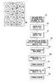
- FIG. 1 is a plan view of a MWP for liquid media exchange of a first embodiment of the present invention
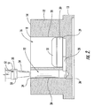
- FIG. 2 is an enlarged, cross-sectional view of a single well and an aspiration hole from the MWP of FIG. 1 ;
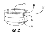
- FIG. 3 is a perspective view of a tip seal of another embodiment of the present invention.
- FIG. 4 is a perspective view of a system for replenishing media in the MWP shown in FIG. 1 of another embodiment of the present invention
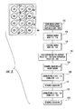
- FIG. 5 is a flow chart of a method of replenishing media using the system of FIG. 4 ;
- FIG. 6 is a sectional view of the well and aspiration hole of FIG. 2 being machined in another embodiment of the present invention.
- a multiple well plate (MWP) 10 of the present invention includes a body 12 having an upper surface 14 .
- the body 12 defines an array of first holes, or wells 16 and an array of second aspiration holes 22 , as shown in FIG. 1 .
- a plurality of channels 28 each connect a respective one of the wells 16 to an adjacent one of the aspiration holes 22 , as shown in FIG. 2 .
- disposed in each of the wells 16 is a porous, hydrophilic frit 30 which supports a tissue sample 32 over a reservoir of liquid media 36 .
- the porous, hydrophilic properties of the frit 30 wick the media 36 upwards, so as to supply the media to the tissue sample 32 .
- the aspiration holes 22 which are each sized and configured to receive a pipette tip 34 .
- the vacuum pressure draws the fluid media 36 out of each of the wells 16 , through the channels 28 , through the adjacent one of the aspiration holes 22 and into the pipette tips.
- the tissue sample 32 is preferably a plant tissue, such as dicot and monocot tissue such as tissue from corn ( Zea mays ), Brassica sp. (e.g., B. napus, B. rapa, B. juncea ), particularly those Brassica species useful as sources of seed oil, alfalfa ( Medicago sativa ), rice ( Oryza sativa ), rye ( Secale cereale ), sorghum ( Sorghum bicolor, Sorghum vulgare ), millet (e.g., pearl millet ( Pennisetum glaucum ), proso millet ( Panicum miliaceum ), foxtail millet ( Setaria italica ), finger millet ( Eleusine coracana )), sunflower ( Helianthus annuus ), safflower ( Carthamus tinctorius ), wheat ( Triticum aestivum ), soybean ( Glycine max ), tobacco ( Nicotiana tabacum ), potato
- the body 12 of the MWP 10 is preferably constructed of a polycarbonate block that can be machined and is resistant enough to heat to be sterilized in an autoclave for reuse. Generally, the hardness of polycarbonate allows it to be machined by computer controlled milling machine (CNC), or other automatic machining process, into complex, precision shapes.
- CNC computer controlled milling machine
- the body could also be constructed of other materials, such as a polystyrene, polysulphone, other synthetic materials, metals, ceramics, glass, etc.
- the body 12 is rectangular in shape, being 5.03 ⁇ 0.01 inches in length, 3.365 ⁇ 0.01 inches in width and 0.813 ⁇ 0.01 inches in height, a configuration compatible with most conventional liquid handling machines.
- the body 12 includes other features such as a base 13 and a pair of 45° chamfers 15 on opposing corners of one width of the body.
- the base 13 provides a ledge and can serve as a gripping or mounting surface in conventional equipment.
- the pair chamfers 15 can serve as reference marks to ensure the proper orientation of the body, especially when it is important to keep track of the location of each well.
- the body 12 also has a flat, upper surface 14 through which the holes 16 and 22 are drilled. It should be noted, that although the size of the body is preferably configured for compatibility with preexisting equipment, the dimensions of the body can be varied as desired.
- the number, dimensions and locations of the wells 16 are also tailored to be compatible with preexisting equipment.
- the plate preferably has 24 wells in an array of 4 by 6, or 48 wells in an array of 6 by 8 to be compatible with most liquid handling devices.
- Other well densities could be used such as 6 wells, or 96 wells that are compatible with conventional devices.
- nonstandard well densities could also be used, such as single well or a 1000 wells.
- the number of wells will be limited by such practicalities as the size of the body 12 , the type of tissue being grown, the capabilities of the equipment using the wells and the size of the wells themselves.
- each of the wells 16 has a standard cylindrical shape with a diameter of 0.62 inches and a depth of 0.60 ⁇ 0.01 inches for the 24 well plate.
- the diameter of each well can be varied as desired, and is based on several factors, such as the initial size of the tissue to be placed in the well, the growth rate of the tissue, and the length of time the tissue is to be propogated in the well before removal.
- a center-to-center distance between the wells is 0.76 inches for the 24 well plate to ensure that the arrangement and motion of standard, automated pipette devices is compatible.
- the 24 well plate has been determined by the inventors to be particularly suitable to the tissue propagation of duckweed callus, presenting a preferred balance of tissue 32 volume and density of wells.
- the density of the cell wells 16 used for duckweed is preferably 96 wells or less due to the size of callus and rapid cell growth. Of course, other arrangements could also be used for more customized equipment, if desired.
- the aspiration holes 22 extend through the upper surface 14 of the body 12 .
- Each of the 24 aspiration holes 22 is preferably adjacent to, and connected in fluid communication with, a respective one of the wells 16 .
- the pairing arrangement of the aspiration holes 22 and the wells 16 allows aspiration without cross-contamination of the samples, such as occurs with the prior art manifold well plates.
- the pairing arrangement allows the media of individual wells 16 of interest to be aspirated and refreshed selectively. Individual wells 16 could be addressed selectively by hand or by automated equipment that allows the operation of a single pipette independently of the other pipettes in the head.
- tissue in one of the wells was generating a strong expression response to an agent, such as increased growth of tissue, increased expression of a polypeptide, added resistance to a selective agent such as a herbicide, or resistance to a plant pathogen.
- an agent such as increased growth of tissue, increased expression of a polypeptide, added resistance to a selective agent such as a herbicide, or resistance to a plant pathogen.
- Other biochemical or biophysical responses could also be assayed in individual wells with the present invention.
- the media from this well could be aspirated and tested more frequently than the other wells. Among other advantages, more frequent collection and testing of media from that well would provide a stronger statistical correlation. If contamination is less of a concern, each of the aspiration holes 22 could be paired with several wells 16 to cut down on the number of aspiration iterations.
- Each of the aspiration holes 22 are also preferably cylindrical in shape with a depth of 0.66 ⁇ 0.01 inches and a diameter of 0.167 inches, so as to be able to receive a standard sized pipette tip 34 through its upper edge 24 . Larger or smaller diameters, and different center-to-center distances could be used, depending upon the size of the pipette tip to be inserted therein. Of course, the other shapes and other dimensions could be varied to suit a customized arrangement, or other standard pipette shapes and lengths that are known to those of skill in the art. Cylindrical aspiration holes 22 are also preferable in that they are easier to machine with rotating drill bits.
- the center-to-center distance between adjacent ones of the aspiration holes 22 is preferably the same as the center-to-center distance between the wells 16 , which is 0.76 inches in the illustrated embodiment of 24 wells.
- the placement of the aspiration holes through the upper surface 14 of the body 12 and the same center-to-center distance ensures that the same pipette head configuration can be used for aspiration of the media 36 as for the dispersion of the media.
- Each of the channels 28 connects a respective pair of the cell wells 16 and aspiration holes 22 in fluid communication, as shown in FIG. 2 .
- Each of the channels 28 is preferably roughly elliptical in shape due to the preferred method of manufacturing used to create the channel, as will be described hereinafter.
- Each of the channels is disposed beneath a bottom portion of one of the wells 16 and the aspiration holes 22 , also due to the preferred method of manufacture. Many types of shapes could be used for the channel 28 as the pressure distribution of the vacuum applied by the pipette 34 will still be evenly distributed throughout the cell well being aspirated.
- Each of the channels 28 acts, along with its respective one of the wells 16 and the holes 22 , as a reservoir for excess media 36 that has not been wicked into the frit 30 .
- the channels 28 and aspiration holes 22 could also be used to supply media 36 .
- Supplying media through the channels 28 and aspiration holes 22 to the wells 16 could be useful, for instance, if the callus of the plant tissue 32 was dense enough to be relatively impermeable to media dispensed into through the upper edge of the wells 16 .
- the width of each of the channels 28 is less than the diameter of its respective one of the wells 16 so as to form a ledge 29 at the bottom of the well for supporting the frit 30 above the media 36 .
- Each frit 30 is preferably constructed of a sintered polyethylene material that is porous and hydrophilic to promote the attraction and retention of the media within its interstices.
- the hydrophilicity of the frit material can be permanent or temporary depending upon the processes by which it is applied, or whether the material is inherently hydrophilic.
- Alternative materials with porous structures could be used and a surfactant could be applied to materials not naturally hydrophilic to make them hydrophilic.
- the material is produced by sintering and wicks solutions by capillary action and can act as a sterile barrier due to its tortuous path properties.
- the frits are preferably cut or punched in disk shapes roughly congruent with the wells 16 from porous 1 ⁇ 4 inch thick polyethylene sheet with an average pore size of 90 to 130 micrometers known as Porex from Porous Products of Fairburn, Ga. and also available as Part No. Y2-PEH-250/90 from Small Parts Inc., Miami Lakes, Fla. Such a frit can hold about 550 ⁇ l of media and supply the tissue for a number of days.
- the congruency of shape between the frit 30 and its respective one of the wells 16 ensures a fit with minimal leakage of the media 36 around the frit and also ensures that the frit rests firmly on the ledge 29 , above most of the media.
- Different thicknesses of the frit 30 may be used, with thicker frits generally holding more material and needing to be refreshed with new media less often.
- a larger diameter frit could be used for larger diameter wells 16 , but may require a manifold underneath for additional support to keep the large diameter frit 30 from collapsing under the applied vacuum pressure. For instance, a large diameter frit 30 could be supported by a screen disposed on the back of the frit material when the frit material is manufactured.
- the frits are typically much stronger than similarly sized membranous or paper supports which cannot withstand even moderate vacuum pressures applied by the pipette tip during aspiration.
- the frit material of the present invention should be able to withstand pressures of about 30 inches of Hg.
- the tissue 32 could be grown on a sheet of the frit material, and then cut or punched into individual frits for placement into the wells 16 .
- the MWP 10 is preferably constructed from a block of polycarbonate material of roughly the same rectangular dimensions as the body 12 . Constructing the plate from a single block of material insures against leakage between wells which could result in cross-contamination of the samples.
- the wells 16 and aspiration holes 22 are preferably formed using a CNC, or other automated drilling machine, with drill bits of similar dimensions to the desired hole dimensions. If necessary, the drilling machine also cuts away enough polycarbonate to form the base 13 , the inset above the base, the chamfers 15 and removes enough material to flatten out other surfaces, such as the upper surface 14 .
- the channel 28 is preferably formed using a rotating saw blade 80 on the same milling machine.
- the rotating saw blade has a cutting diameter of slightly less than the wells 16 and is inserted into one of the wells until it cuts away to a depth equal to the thickness of the rotating saw blade 80 , as shown in FIG. 6 .
- the rotating saw blade is then advanced in the direction of the adjacent one of the aspiration holes 22 until it cuts into the aspiration hole enough to form the channel 28 with sufficient size to enable fluid communication between the well and the aspiration hole, as shown in FIG. 2 .
- the saw blade 80 is then moved back to the center of the well and retracted out of the well.
- the undersized diameter of the saw blade forms the ledge 29 on which the frit 30 is supported.
- the present invention can also include a seal 35 that embraces the pipette tip 34 and is disposed around the upper edge 24 of one of the aspiration holes 22 when the tip is inserted therein.
- the seal 35 includes an elastomeric ring 50 subjacent a rigid collar 51 .
- the rigid collar is preferably constructed from a stiff material, such as from a steel bushing, and optionally includes a set screw 52 extending through its side. Tightening of the set screw tightens the collar about the pipette tip 34 allowing the rigid collar 51 to prevent upward migration of the elastomeric ring 50 as it is pressed against the upper edge 24 of the aspiration hole.
- the end of the elastomeric ring 50 that makes contact with the upper edge 24 of the aspiration hole can have a frustoconical shape with a preferred angle of about 70° to further facilitate formation of a vacuum-tight seal.
- the seal 35 is approximately 0.3 inches in diameter and 0.5 inches long so as to fit a standard pipette tip.
- TECAN pipette tip No. 71-700S with a PTFE (TEFLON) coating an inside point diameter of 0.5 mm, outside point diameter of 1.1 mm, inside body diameter of 1.5 mm and an outside body diameter of 2.0 mm.
- the elastomeric ring 50 may also be configured to fit any type of pipette tip by sizing its aperture 53 to be about 90% of the widest outside diameter of the pipette tip, allowing the seal to compress around the tip while relaxing to its normal shape when removed from the aspiration hole.
- the rigid collar 51 has an aperture that is oversized 10% with respect to the outside diameter of the pipette tip 34 allowing it to easily receive the pipette tip. The collar's aperture is decreased when the set screw 52 is tightened to secure the collar about the pipette tip 34 .
- the seal 35 could also be integrally molded with the pipette tip 34 .
- a soft sealing material could be used around the upper edge 24 of the aspiration holes so as to sealingly receive a tip without the seal 35 .
- the MWP 10 is used to promote tissue growth and propagation by supplying nutrients in a sterile environment.
- the method for using the MWP includes loading the plate either manually, or using a cell-sorter modified to sort tissue samples, such as those used to sort fruit flies. Generally, this equipment uses a vacuum to pick up the samples. The unmodified cell sorter could be used if the tissue samples are small enough.
- the MWP 10 is preferably covered with a transparent, polystyrene cover or lid to allow the transmission of light to the tissue.
- the plate is stacked for access by a liquid handler including multiple pipette tips connected to media and vacuum supplies.
- the liquid handler grips the plate and removes the lid in a manner known to those of skill in the art.
- the liquid handling device extends each pipette tip 34 into a respective one of the aspiration holes 22 until the seal 35 abuts the upper edge 24 of the aspiration hole and the portion of the upper surface 14 thereabout.
- the liquid handling device dispenses media through the tips, into the aspiration holes 22 , through the channels 28 and into the wells 16 . In this manner, the tissue 32 in each of the wells 16 has access to a supply of the media through the frit 30 .
- the lid is replaced on the plate 10 and the plate is placed in a culture room with illumination to promote growth (in the case of plant tissues).
- the plate 10 is loaded back on the liquid handling device.
- the lid is removed from the plate.
- the liquid handling device extends each pipette tip 34 into a respective one of the aspiration holes 22 until the seal 35 abuts the upper edge 24 of the aspiration hole and the portion of the upper surface 14 thereabout.
- the liquid handling device applies a vacuum or suction pressure through the pipette tips which draws the media from the cell wells 16 , through the channels 28 , into the aspiration holes 22 and into the pipette tips to complete aspiration.
- the media is cycled as often as needed by repeating the above process.
- an automated pipetting head (or robotic liquid handler) 60 is used to address single or multiple wells selectively, such as the GENESIS liquid handler (TECAN, AG of Switzerland), shown in FIG. 4 .
- the robot is upgraded with a six-way valve for switching between different media, reagent and ethanol supplies.
- the robot includes eight pipetting tips 61 on its liquid handling arm 62 .
- Four of the tips are configured to deliver media to a plurality of multiple well plates 63 supported on its deck 64 .
- the four remaining tips are each fitted with a tip seal allowing the four remaining tips to aspirate the wells 16 through their respective aspiration holes 22 .
- the robotic liquid handler 60 is operated using a software program to control deployment of its pipetting tips 61 in such a way as to minimize cross-contamination between the wells 16 .
- contamination of the four media supplying tips is avoided by suspending the media supplying tips over the wells without contacting the plates.
- Contamination of the aspiration tips is avoided by flushing each tip with an anti-microbial ethanol liquid in between aspiration cycles.
- the exterior of the tips and seals are washed in an on-deck shallow wash station 65 , also filled with ethanol liquid. The ethanol is pumped by a syringe pump and/or a high-speed diaphragm (fast wash) pump from a reservoir accessible through the six way valve.
- Programming the robot 60 to access the correct holes requires teaching the robot the location of both the aspiration holes 22 and the wells 16 .
- the robot is operated as if the plate 10 has twice as many wells because the aspiration holes 22 are positioned to correspond to the wells of a plate having twice the density.
- the fact that the aspiration holes have a smaller diameter than the wells 16 is of no consequence as the robot seeks the center of the aspiration holes 22 .
- the robot is programmed to access a 24 well plate as if it had 48 wells, each well having a diameter equal to that of the aspiration holes.
- the programming of the well centers (or their locations with respect to the aspiration holes) can be considerably off because of the much smaller diameter of the pipette tips 61 with respect to the wells.
- FIG. 5 depicts one example of how the robot 60 can be programmed to address the wells 16 and aspiration holes 22 of the plate 10 .
- the four media supply tips are positioned above wells 105 through 108 and, without contacting the plate 10 , dispense media into the wells in step 125 .
- the media supply tips are then sequentially positioned above, and dispense media into, wells 113 through 116 and 121 through 124 in steps 126 and 127 , respectively.
- the four aspiration tips are then inserted into the aspiration holes (which the robot recognizes as “wells”) 101 through 104 , aspirating spent media from wells 105 through 108 , in step 128 .
- the aspiration tips are flushed internally and cleansed externally with ethanol at the wash station 65 , in step 129 .
- Aspiration and cleaning are alternated for holes 109 through 112 , in steps 130 and 131 , and again for aspiration holes 117 through 120 in steps 132 and 133 .
- the process can be expanded or reduced depending upon the number of pipetting tips and the number of wells.
- the process is preferably performed within a HEPA filtered environment, such as within a pressurized and filtered hood, to minimize the occurrence of contamination.
- the robot 60 can also be used in conjunction with a high-density hotel or rack for holding and supplying light to the tissue in hundreds of the plates, as described in commonly owned U.S. patent application Ser. No. 10/080,918 entitled, “LED Array for Illuminating Cell Well Plates and Automated Rack System for Handling the Same,” which is incorporated herein by reference.
- the automated rack system uses its own robot to manipulate and present the plates to the robot of the present system.
- the well plate and method of the present invention could be used to perform solid phase extraction.
- Each well of the well plate contains a matrix trapped between a pair of frits which form a column.
- Various compounds (such as a ligands, or antibodies) are forced through the column and become trapped within the matrix.
- an agent can be forced through the column to breakup the solid phase.
- High-throughput distribution and retrieval of the compound, agents, etc. could be handled by an automated pipetting head using the wells and their respective aspiration holes.
- the present invention has several advantages.
- the tissue samples 32 in the wells 16 do not have to be moved or disturbed, cutting down on workload, ensuring sterile and optimal growth conditions.
- the plates 10 may be used with conventional liquid handling pipette heads because the aspiration holes 22 are accessible from the upper surface of the body, i.e., a top-loading arrangement.
- the use of robotic liquid handlers with the plate promotes a well-to-well consistency in the treatment of the tissue, as well as the efficient removal and replacement of the media 36 .
- the top-loading aspect allows the use of a standard lid for sterility control and removes the need for a separate vacuum manifold station for pulling out media.
- the lack of a manifold allows for the differential treatment of each well and provides flexibility in liquid handler design and selection.
- the liquid head can be configured to remove the media as well as add new media with no change of tooling or pipette tips.
- FIG. 1 Some of the figures disclosed herein contain block diagrams, flowcharts and control flow illustrations of methods, systems and program products according to the invention. It will be understood that each block or step of the block diagram, flowchart and control flow illustration, and combinations of blocks in the block diagram, flowchart and control flow illustration, can be implemented by computer program instructions. These computer program instructions may be loaded onto a computer or other programmable apparatus to produce a machine, such that the instructions which execute on the computer or other programmable apparatus create means for implementing the functions specified in the block diagram, flowchart or control flow block(s) or step(s).
- These computer program instructions may also be stored in a computer-readable memory that can direct a computer or other programmable apparatus to function in a particular manner, such that the instructions stored in the computer-readable memory produce an article of manufacture including instruction means which implement the function specified in the block diagram, flowchart or control flow block(s) or step(s).
- the computer program instructions may also be loaded onto a computer or other programmable apparatus to cause a series of operational steps to be performed on the computer or other programmable apparatus to produce a computer implemented process such that the instructions which execute on the computer or other programmable apparatus provide steps for implementing the functions specified in the block diagram, flowchart or control flow block(s) or step(s).
- blocks or steps of the block diagram, flowchart or control flow illustration support combinations of means for performing the specified functions, combinations of steps for performing the specified functions and program instruction means for performing the specified functions. It will also be understood that each block or step of the block diagram, flowchart or control flow illustration, and combinations of blocks or steps in the block diagram, flowchart or control flow illustration, can be implemented by special purpose hardware-based computer systems which perform the specified functions or steps, or combinations of special purpose hardware and computer instructions.
Abstract
A multiple well plate and method for media exchange, including a body defining a plurality of cell wells each connected via a channel to one of a plurality of aspiration holes, is provided. The cell wells contain a porous, hydrophilic frit which is suspended on a ledge above a reservoir of fluid media and supports a tissue sample. The properties of the frit wick the fluid media upwards to supply the tissue sample with nutrients for growth and proliferation. Old media is aspirated from the wells by a liquid handling device which inserts a pipette tip into the aspiration holes. The pipette tip applies a suction pressure which draws the media out of the cell well, through the channel, into the aspiration hole and out through the pipette tip. New media is dispersed through the pipette tip and directly into the cell well.
Description
- The present application is a divisional of U.S. application Ser. No. 10/157,562, filed May 29, 2002, which claims the benefit of U.S. Provisional Application No. 60/294,430, filed May 30, 2001, both of which are hereby incorporated herein in their entirety by reference.
- The present invention relates to devices and methods for promoting the growth of tissue in experimental and production settings, more particularly the use of specialized plates to house the tissue and the cycling of media to biologically sustain the tissue.
- High-throughput screening typically requires parallel processing of batches of samples, typically in multiple well plates (MWPs) of 24, 48, 96, and 384, or more, wells per plate. MWPs are standard sizes that can be used with existing high-throughput machinery, such as with robotic-controlled pipetters. Each pipetting station of a robotic controlled pipetter employs pipetting heads having an array of pipette tips that address multiple wells simultaneously. Although used effectively for the screening of liquid samples, the current multiple well plates are generally ineffective for screening plant and other tissues, and the secretory products associated with these tissues, that require, or prefer, more complex environments such as solid support structures.
- For example, attempts have been made to grow plants in MWPs by suspending the plants in a liquid media within each well. However, the plant tissue is deprived of oxygen when sitting in the liquid, effectively “drowning” the plant tissue in an anaerobic environment. Other attempts have been made using media that are generally more solid and provide a substrate on which the plant tissue may be supported above the fluid, such as a gel or filter paper disk. Although these types of supports avoid drowning the plants, they are difficult to exchange and replenish when the nutrients or media have been depleted. Paper bridges doused in liquid media have also been used as tissue supports and the liquid media is somewhat more easily replenished. However, empirical evidence has shown that paper bridges are difficult to manage in an automated system and are generally ineffective at promoting plant tissue growth. Without being wed to any particular theory, this may be because the liquid media does not easily penetrate the paper bridge (i.e., the paper bridge is only mildly hydrophilic) and the tissue supported thereon lacks a continuous supply of media.
- A common approach to supplying fresh media to plant tissue is to move the plant tissue to a container holding fresh media. Movement of the plant tissue is a relatively slow and labor intensive process, as multiple plates must be replenished and otherwise prepared for each batch of plant tissue. In addition there is a threat of loss or contamination of the tissue samples when they are removed from the wells.
- Another approach to aspirating and removing spent media and tissue byproducts is to use an assay plate having a plurality of wells, with each well having a hole or port at the base of the well. A filter is positioned at the bottom of each well to support the tissue. Spent media can be vacuum harvested from each well through the port using a vacuum manifold assembly. One example of a vacuum manifold assembly is the MultiScreen Vacuum Manifold system manufactured by MILLIPORE of Bedford, Mass. The assay plate rests on a manifold that supplies a vacuum which draws the media through the filter disks, out of the cell wells and through the ports, where it is captured in the manifold below. Although the filter disks in the assay plate allow media to be drawn out of the plate, it is difficult for the filter disks to retain enough media to support tissue maintenance and growth for any length of time. Because the ports at the bottom of the wells are open to the ambient air, the ports may allow media to leak or evaporate and may also provide a path for microbial contamination of the wells. In addition, the wells of the assay plate cannot be individually sampled because the vacuum manifold harvests the media from all of the wells at once.
- The tissue of animals, and other types of organisms may also require, or prefer, solid support structures that inhibit the use of multiple well plates and high-throughput screening techniques. For instance, the growth of cartilage cells may be promoted by the use of a collagen fibril matrix that simulates an in vivo environment. Similar to the plant tissue discussed above, the cartilage cells need a supply of fresh media that is replenished at various intervals to survive and/or proliferate. In addition, some of the cartilage cells proliferate within the collagen fibril matrix and cannot be moved independent of the matrix. Moving the cells to a new plate with a fresh supply of media requires movement of the entire collagen matrix which is a relatively slow and inefficient process that exposes the tissue to contamination.
- It would be advantageous to have a multiple well plate that allows the use of high throughput screening methods for non-liquid samples. In addition, it would be advantageous to have a multiple well plate that allows the use of high throughput screening methods for tissues that require, or prefer, solid support structures. It would be further advantageous to have a multiple well plate that promotes the growth of tissue, such as plant tissue, without posing the risk of drowning the tissue in liquid media or allowing the tissue to dehydrate or become contaminated. It would also be advantageous to have a multiple well plate that allows media to be easily replenished, without undue disturbance of the tissue contained in the wells. Additionally, it would be advantageous to have the capability of sampling less than the total number of wells in the plate without disturbing the unsampled wells.
- The present invention addresses the above needs and achieves other advantages by providing a multiple well plate (MWP) and method for media exchange that promotes the growth of plant tissue, and other types of tissue, by controlling the supply of media to the tissue and allowing for the regular exchange (removal and addition) of media without disturbing the tissue. The MWP includes an array of wells, with each well being coupled with an adjacent aspiration hole that allows media to be aspirated from the wells using a conventional, automated pipette head. The MWP and pipette head provide a virtually complete exchange of the spent media because of the novel dual-well architecture. A hydrophilic, porous frit housed within each well supports the tissue and holds the media in its interstices, allowing contact between the tissue and the media while avoiding an anaerobic condition. The media is wicked upwards in sufficient quantities to provide nutrients to the tissue and promote proliferation of the tissue.
- In one embodiment, the invention includes a plate for holding a porous frit that supports a tissue. The porous frit is saturated in a media that may be regularly aspirated and refreshed, for example, by a top-loading pipette device. The plate comprises a body with an upper surface defining a first hole and a second hole. The first hole has a first hole upper edge defined by the upper surface of the body and a first hole bottom portion defined within the body and below the upper surface of the body. The first hole is configured to receive the porous frit and the tissue, and to hold the media bathing the porous frit and the tissue. The second hole has a second hole upper edge defined by the upper surface of the body and a second hole bottom portion defined within the body and below the upper surface of the body. The second hole bottom portion is in fluid communication with the first hole bottom portion so that the pipette device can access the second hole upper edge to aspirate the media by applying a vacuum. The pipette device also refreshes the media by adding fresh media directly onto the frit in each well.
- In another aspect, the body of the plate further defines a passage connecting the first hole bottom portion and the second hole bottom portion in fluid communication. The body may further include a ledge protruding into the first hole bottom portion for supporting the frit above a reservoir of fluid. The body may also define a plurality of the first and second holes, with each first hole in fluid communication with a respective one of the second holes to form a MWP. In another aspect, the body defines an array of first and second holes, for example 12, 24, 48, 96, 384, or 1536 first and second holes, wherein each first hole is in fluid communication with a respective one of the second holes. The first and second holes preferably have cylindrical shapes.
- In yet another aspect, the top surface of the body is configured to receive a cover plate disposed thereon. Preferably the cover plate is transparent to light transmission and the first hole upper edge is configured to also allow light transmission, thereby promoting plant tissue growth.
- In another embodiment, the present invention includes a method of making a plate for holding a porous frit that supports a tissue wherein the porous frit is saturated in a media. The media is regularly aspirated and refreshed by a pipette device to promote proliferation of the tissue. The method includes providing a body with an upper surface and defining a first and second holes in the body. Defining a first hole in the body includes drilling through the upper surface of the body to form a first hole upper edge and drilling below the upper surface to form a first hole bottom portion. The second hole is defined by drilling through the upper surface of the body to form a second hole upper edge and drilling below the upper surface to form a second hole bottom portion. The first and second hole bottom portions are connected in fluid communication by forming a passage in the body and between the first hole bottom portion and the second hole bottom portion. Preferably, the passage is formed by inserting a saw disc into the first hole bottom portion and moving the saw laterally until encountering the second hole bottom portion.
- In yet another embodiment, the present invention includes a method of using a MWP. A frit is placed into each of the plurality of first holes and tissue, preferably a duckweed or other plant tissue, is placed onto the frit. A media is dispensed into each of the plurality of first holes. A pipette is inserted into each of the plurality of second holes and used to aspirate the media from the first holes. The media is aspirated by applying a suction pressure to the second holes using the pipette. The suction pressure draws the media from the first hole, into the second hole and into the pipette so as to flush the media from the plate. Fresh media can be re-dispensed into the plurality of first holes after aspirating the media from the second holes.
- In still another embodiment, the present invention includes a frit material for supporting a tissue having a porous structure, a top surface and a bottom surface. The porous structure has hydrophilic properties and a plurality of interstices. The top surface is configured to support the tissue. The bottom surface is in fluid communication with a reservoir of fluid media. The hydrophilic properties of the porous structure wick the fluid into its interstices so that the supported tissue is supplied with sufficient liquid media from the reservoir to promote growth of the tissue.
- The present invention has several advantages. For example, the tissue samples in the wells do not have to be moved or disturbed when the provided media is spent, cutting down on workload and ensuring sterile and optimal growth conditions. The plates may be used with conventional liquid handling pipette heads of the fixed tip or individually controllable tip versions because the aspiration holes are accessible from the upper surface of the body, i.e., a top-loading arrangement. The use of robotic liquid handlers with the plate promotes a well-to-well consistency in the treatment of the tissue, as well as the efficient removal and replacement of the media. The top-loading aspect allows the use of a standard lid for sterility control and removes the need for a separate vacuum manifold station for pulling out media. The lack of a manifold allows for the differential treatment of each well and provides flexibility in liquid handler design and selection, as well as experimental model and sample interrogation functions. The liquid head can be configured to remove the media as well as add new media with no change of tooling or pipette tips.
- Having thus described the invention in general terms, reference will now be made to the accompanying drawings, which are not necessarily drawn to scale, and wherein:
-
FIG. 1 is a plan view of a MWP for liquid media exchange of a first embodiment of the present invention; -
FIG. 2 is an enlarged, cross-sectional view of a single well and an aspiration hole from the MWP ofFIG. 1 ; -
FIG. 3 is a perspective view of a tip seal of another embodiment of the present invention; -
FIG. 4 is a perspective view of a system for replenishing media in the MWP shown inFIG. 1 of another embodiment of the present invention; -
FIG. 5 is a flow chart of a method of replenishing media using the system ofFIG. 4 ; and -
FIG. 6 is a sectional view of the well and aspiration hole ofFIG. 2 being machined in another embodiment of the present invention. - The present invention now will be described more fully hereinafter with reference to the accompanying drawings, in which preferred embodiments of the invention are shown. This invention may, however, be embodied in many different forms and should not be construed as limited to the embodiments set forth herein; rather, these embodiments are provided so that this disclosure will be thorough and complete, and will fully convey the scope of the invention to those skilled in the art. Like numbers refer to like elements throughout.
- A multiple well plate (MWP) 10 of the present invention includes a
body 12 having anupper surface 14. Thebody 12 defines an array of first holes, orwells 16 and an array of second aspiration holes 22, as shown inFIG. 1 . A plurality ofchannels 28 each connect a respective one of thewells 16 to an adjacent one of the aspiration holes 22, as shown inFIG. 2 . In one embodiment, disposed in each of thewells 16 is a porous,hydrophilic frit 30 which supports atissue sample 32 over a reservoir ofliquid media 36. The porous, hydrophilic properties of the frit 30 wick themedia 36 upwards, so as to supply the media to thetissue sample 32. Exchange of old,depleted media 36 is facilitated by the aspiration holes 22 which are each sized and configured to receive apipette tip 34. During aspiration, several of the pipette tips are inserted into the aspiration holes 22 and apply a vacuum pressure. The vacuum pressure draws thefluid media 36 out of each of thewells 16, through thechannels 28, through the adjacent one of the aspiration holes 22 and into the pipette tips. - The
tissue sample 32 is preferably a plant tissue, such as dicot and monocot tissue such as tissue from corn (Zea mays), Brassica sp. (e.g., B. napus, B. rapa, B. juncea), particularly those Brassica species useful as sources of seed oil, alfalfa (Medicago sativa), rice (Oryza sativa), rye (Secale cereale), sorghum (Sorghum bicolor, Sorghum vulgare), millet (e.g., pearl millet (Pennisetum glaucum), proso millet (Panicum miliaceum), foxtail millet (Setaria italica), finger millet (Eleusine coracana)), sunflower (Helianthus annuus), safflower (Carthamus tinctorius), wheat (Triticum aestivum), soybean (Glycine max), tobacco (Nicotiana tabacum), potato (Solanum tuberosum), peanuts (Arachis hypogaea), cotton (Gossypium barbadense, Gossypium hirsutum), sweet potato (Ipomoea batatus), cassaya (Manihot esculenta), coffee (Coffea spp.), coconut (Cocos nucifera), pineapple (Ananas comosus), citrus trees (Citrus spp.), cocoa (Theobroma cacao), tea (Camellia sinensis), banana (Musa spp.), avocado (Persea americana), fig (Ficus casica), guava (Psidium guajava), mango (Mangifera indica), olive (Olea europaea), papaya (Carica papaya), cashew (Anacardium occidentale), macadamia (Macadamia integrifolia), almond (Prunus amygdalus), sugar beets (Beta vulgaris), sugarcane (Saccharum spp.), oats, barley, vegetables, ornamentals, and conifers. In some embodiments the tissue is callus tissue from duckweed or gymnosperms. The present invention may be particularly effective with plant tissues that thrive with minimal fluid, such as tissue derived from gymnosperms. - The
body 12 of theMWP 10 is preferably constructed of a polycarbonate block that can be machined and is resistant enough to heat to be sterilized in an autoclave for reuse. Generally, the hardness of polycarbonate allows it to be machined by computer controlled milling machine (CNC), or other automatic machining process, into complex, precision shapes. The body could also be constructed of other materials, such as a polystyrene, polysulphone, other synthetic materials, metals, ceramics, glass, etc. Thebody 12 is rectangular in shape, being 5.03±0.01 inches in length, 3.365±0.01 inches in width and 0.813±0.01 inches in height, a configuration compatible with most conventional liquid handling machines. Thebody 12 includes other features such as abase 13 and a pair of 45°chamfers 15 on opposing corners of one width of the body. Thebase 13 provides a ledge and can serve as a gripping or mounting surface in conventional equipment. The pair chamfers 15 can serve as reference marks to ensure the proper orientation of the body, especially when it is important to keep track of the location of each well. Thebody 12 also has a flat,upper surface 14 through which theholes - The number, dimensions and locations of the
wells 16 are also tailored to be compatible with preexisting equipment. For instance, the plate preferably has 24 wells in an array of 4 by 6, or 48 wells in an array of 6 by 8 to be compatible with most liquid handling devices. Other well densities could be used such as 6 wells, or 96 wells that are compatible with conventional devices. However, nonstandard well densities could also be used, such as single well or a 1000 wells. Generally the number of wells will be limited by such practicalities as the size of thebody 12, the type of tissue being grown, the capabilities of the equipment using the wells and the size of the wells themselves. - Preferably, each of the
wells 16 has a standard cylindrical shape with a diameter of 0.62 inches and a depth of 0.60±0.01 inches for the 24 well plate. The diameter of each well can be varied as desired, and is based on several factors, such as the initial size of the tissue to be placed in the well, the growth rate of the tissue, and the length of time the tissue is to be propogated in the well before removal. A center-to-center distance between the wells is 0.76 inches for the 24 well plate to ensure that the arrangement and motion of standard, automated pipette devices is compatible. The 24 well plate has been determined by the inventors to be particularly suitable to the tissue propagation of duckweed callus, presenting a preferred balance oftissue 32 volume and density of wells. The density of thecell wells 16 used for duckweed is preferably 96 wells or less due to the size of callus and rapid cell growth. Of course, other arrangements could also be used for more customized equipment, if desired. - The aspiration holes 22 extend through the
upper surface 14 of thebody 12. Each of the 24 aspiration holes 22 is preferably adjacent to, and connected in fluid communication with, a respective one of thewells 16. The pairing arrangement of the aspiration holes 22 and thewells 16 allows aspiration without cross-contamination of the samples, such as occurs with the prior art manifold well plates. In addition, the pairing arrangement allows the media ofindividual wells 16 of interest to be aspirated and refreshed selectively.Individual wells 16 could be addressed selectively by hand or by automated equipment that allows the operation of a single pipette independently of the other pipettes in the head. Selectively addressing wells would be useful if, for instance, the tissue in one of the wells was generating a strong expression response to an agent, such as increased growth of tissue, increased expression of a polypeptide, added resistance to a selective agent such as a herbicide, or resistance to a plant pathogen. Other biochemical or biophysical responses could also be assayed in individual wells with the present invention. The media from this well could be aspirated and tested more frequently than the other wells. Among other advantages, more frequent collection and testing of media from that well would provide a stronger statistical correlation. If contamination is less of a concern, each of the aspiration holes 22 could be paired withseveral wells 16 to cut down on the number of aspiration iterations. - Each of the aspiration holes 22 are also preferably cylindrical in shape with a depth of 0.66±0.01 inches and a diameter of 0.167 inches, so as to be able to receive a standard
sized pipette tip 34 through itsupper edge 24. Larger or smaller diameters, and different center-to-center distances could be used, depending upon the size of the pipette tip to be inserted therein. Of course, the other shapes and other dimensions could be varied to suit a customized arrangement, or other standard pipette shapes and lengths that are known to those of skill in the art. Cylindrical aspiration holes 22 are also preferable in that they are easier to machine with rotating drill bits. The center-to-center distance between adjacent ones of the aspiration holes 22 is preferably the same as the center-to-center distance between thewells 16, which is 0.76 inches in the illustrated embodiment of 24 wells. The placement of the aspiration holes through theupper surface 14 of thebody 12 and the same center-to-center distance ensures that the same pipette head configuration can be used for aspiration of themedia 36 as for the dispersion of the media. - Each of the
channels 28 connects a respective pair of thecell wells 16 and aspiration holes 22 in fluid communication, as shown inFIG. 2 . Each of thechannels 28 is preferably roughly elliptical in shape due to the preferred method of manufacturing used to create the channel, as will be described hereinafter. Each of the channels is disposed beneath a bottom portion of one of thewells 16 and the aspiration holes 22, also due to the preferred method of manufacture. Many types of shapes could be used for thechannel 28 as the pressure distribution of the vacuum applied by thepipette 34 will still be evenly distributed throughout the cell well being aspirated. Each of thechannels 28 acts, along with its respective one of thewells 16 and theholes 22, as a reservoir forexcess media 36 that has not been wicked into thefrit 30. In addition to supplying a vacuum for aspiration, thechannels 28 and aspiration holes 22 could also be used to supplymedia 36. Supplying media through thechannels 28 and aspiration holes 22 to thewells 16 could be useful, for instance, if the callus of theplant tissue 32 was dense enough to be relatively impermeable to media dispensed into through the upper edge of thewells 16. Preferably, the width of each of thechannels 28 is less than the diameter of its respective one of thewells 16 so as to form aledge 29 at the bottom of the well for supporting the frit 30 above themedia 36. - Each
frit 30 is preferably constructed of a sintered polyethylene material that is porous and hydrophilic to promote the attraction and retention of the media within its interstices. The hydrophilicity of the frit material can be permanent or temporary depending upon the processes by which it is applied, or whether the material is inherently hydrophilic. Alternative materials with porous structures could be used and a surfactant could be applied to materials not naturally hydrophilic to make them hydrophilic. The material is produced by sintering and wicks solutions by capillary action and can act as a sterile barrier due to its tortuous path properties. The frits are preferably cut or punched in disk shapes roughly congruent with thewells 16 from porous ¼ inch thick polyethylene sheet with an average pore size of 90 to 130 micrometers known as Porex from Porous Products of Fairburn, Ga. and also available as Part No. Y2-PEH-250/90 from Small Parts Inc., Miami Lakes, Fla. Such a frit can hold about 550 μl of media and supply the tissue for a number of days. - The congruency of shape between the frit 30 and its respective one of the
wells 16 ensures a fit with minimal leakage of themedia 36 around the frit and also ensures that the frit rests firmly on theledge 29, above most of the media. Different thicknesses of the frit 30 may be used, with thicker frits generally holding more material and needing to be refreshed with new media less often. A larger diameter frit could be used forlarger diameter wells 16, but may require a manifold underneath for additional support to keep thelarge diameter frit 30 from collapsing under the applied vacuum pressure. For instance, alarge diameter frit 30 could be supported by a screen disposed on the back of the frit material when the frit material is manufactured. Despite the possible need for a supporting manifold, the frits are typically much stronger than similarly sized membranous or paper supports which cannot withstand even moderate vacuum pressures applied by the pipette tip during aspiration. Preferably, the frit material of the present invention should be able to withstand pressures of about 30 inches of Hg. In yet another embodiment, thetissue 32 could be grown on a sheet of the frit material, and then cut or punched into individual frits for placement into thewells 16. - The
MWP 10 is preferably constructed from a block of polycarbonate material of roughly the same rectangular dimensions as thebody 12. Constructing the plate from a single block of material insures against leakage between wells which could result in cross-contamination of the samples. Thewells 16 and aspiration holes 22 are preferably formed using a CNC, or other automated drilling machine, with drill bits of similar dimensions to the desired hole dimensions. If necessary, the drilling machine also cuts away enough polycarbonate to form thebase 13, the inset above the base, thechamfers 15 and removes enough material to flatten out other surfaces, such as theupper surface 14. Thechannel 28 is preferably formed using a rotatingsaw blade 80 on the same milling machine. The rotating saw blade has a cutting diameter of slightly less than thewells 16 and is inserted into one of the wells until it cuts away to a depth equal to the thickness of the rotatingsaw blade 80, as shown inFIG. 6 . The rotating saw blade is then advanced in the direction of the adjacent one of the aspiration holes 22 until it cuts into the aspiration hole enough to form thechannel 28 with sufficient size to enable fluid communication between the well and the aspiration hole, as shown inFIG. 2 . Thesaw blade 80 is then moved back to the center of the well and retracted out of the well. The undersized diameter of the saw blade forms theledge 29 on which thefrit 30 is supported. - As shown in
FIGS. 2 and 3 , the present invention can also include aseal 35 that embraces thepipette tip 34 and is disposed around theupper edge 24 of one of the aspiration holes 22 when the tip is inserted therein. Theseal 35 includes anelastomeric ring 50 subjacent arigid collar 51. The rigid collar is preferably constructed from a stiff material, such as from a steel bushing, and optionally includes aset screw 52 extending through its side. Tightening of the set screw tightens the collar about thepipette tip 34 allowing therigid collar 51 to prevent upward migration of theelastomeric ring 50 as it is pressed against theupper edge 24 of the aspiration hole. The end of theelastomeric ring 50 that makes contact with theupper edge 24 of the aspiration hole can have a frustoconical shape with a preferred angle of about 70° to further facilitate formation of a vacuum-tight seal. Further preferably, theseal 35 is approximately 0.3 inches in diameter and 0.5 inches long so as to fit a standard pipette tip. For instance, TECAN pipette tip No. 71-700S with a PTFE (TEFLON) coating, an inside point diameter of 0.5 mm, outside point diameter of 1.1 mm, inside body diameter of 1.5 mm and an outside body diameter of 2.0 mm. - The
elastomeric ring 50 may also be configured to fit any type of pipette tip by sizing itsaperture 53 to be about 90% of the widest outside diameter of the pipette tip, allowing the seal to compress around the tip while relaxing to its normal shape when removed from the aspiration hole. Conversely, therigid collar 51 has an aperture that is oversized 10% with respect to the outside diameter of thepipette tip 34 allowing it to easily receive the pipette tip. The collar's aperture is decreased when theset screw 52 is tightened to secure the collar about thepipette tip 34. In an alternative embodiment, theseal 35 could also be integrally molded with thepipette tip 34. In yet another embodiment, a soft sealing material could be used around theupper edge 24 of the aspiration holes so as to sealingly receive a tip without theseal 35. - The
MWP 10 is used to promote tissue growth and propagation by supplying nutrients in a sterile environment. The method for using the MWP includes loading the plate either manually, or using a cell-sorter modified to sort tissue samples, such as those used to sort fruit flies. Generally, this equipment uses a vacuum to pick up the samples. The unmodified cell sorter could be used if the tissue samples are small enough. TheMWP 10 is preferably covered with a transparent, polystyrene cover or lid to allow the transmission of light to the tissue. - Once the
tissue 32 is in thewells 16 of the plate, the plate is stacked for access by a liquid handler including multiple pipette tips connected to media and vacuum supplies. The liquid handler grips the plate and removes the lid in a manner known to those of skill in the art. The liquid handling device extends eachpipette tip 34 into a respective one of the aspiration holes 22 until theseal 35 abuts theupper edge 24 of the aspiration hole and the portion of theupper surface 14 thereabout. The liquid handling device dispenses media through the tips, into the aspiration holes 22, through thechannels 28 and into thewells 16. In this manner, thetissue 32 in each of thewells 16 has access to a supply of the media through thefrit 30. The lid is replaced on theplate 10 and the plate is placed in a culture room with illumination to promote growth (in the case of plant tissues). - After the tissue depletes essential nutrients in the
media 36, or the media otherwise needs to be changed, theplate 10 is loaded back on the liquid handling device. The lid is removed from the plate. The liquid handling device extends eachpipette tip 34 into a respective one of the aspiration holes 22 until theseal 35 abuts theupper edge 24 of the aspiration hole and the portion of theupper surface 14 thereabout. The liquid handling device applies a vacuum or suction pressure through the pipette tips which draws the media from thecell wells 16, through thechannels 28, into the aspiration holes 22 and into the pipette tips to complete aspiration. The media is cycled as often as needed by repeating the above process. - In another embodiment, an automated pipetting head (or robotic liquid handler) 60 is used to address single or multiple wells selectively, such as the GENESIS liquid handler (TECAN, AG of Switzerland), shown in
FIG. 4 . The robot is upgraded with a six-way valve for switching between different media, reagent and ethanol supplies. The robot includes eight pipetting tips 61 on itsliquid handling arm 62. Four of the tips are configured to deliver media to a plurality of multiplewell plates 63 supported on itsdeck 64. The four remaining tips are each fitted with a tip seal allowing the four remaining tips to aspirate thewells 16 through their respective aspiration holes 22. - Preferably, the robotic liquid handler 60 is operated using a software program to control deployment of its pipetting tips 61 in such a way as to minimize cross-contamination between the
wells 16. During media delivery, contamination of the four media supplying tips is avoided by suspending the media supplying tips over the wells without contacting the plates. Contamination of the aspiration tips is avoided by flushing each tip with an anti-microbial ethanol liquid in between aspiration cycles. The exterior of the tips and seals are washed in an on-deckshallow wash station 65, also filled with ethanol liquid. The ethanol is pumped by a syringe pump and/or a high-speed diaphragm (fast wash) pump from a reservoir accessible through the six way valve. - Programming the robot 60 to access the correct holes requires teaching the robot the location of both the aspiration holes 22 and the
wells 16. In this manner, the robot is operated as if theplate 10 has twice as many wells because the aspiration holes 22 are positioned to correspond to the wells of a plate having twice the density. The fact that the aspiration holes have a smaller diameter than thewells 16 is of no consequence as the robot seeks the center of the aspiration holes 22. For instance, the robot is programmed to access a 24 well plate as if it had 48 wells, each well having a diameter equal to that of the aspiration holes. Notably, the programming of the well centers (or their locations with respect to the aspiration holes) can be considerably off because of the much smaller diameter of the pipette tips 61 with respect to the wells. -
FIG. 5 depicts one example of how the robot 60 can be programmed to address thewells 16 and aspiration holes 22 of theplate 10. First, the four media supply tips are positioned abovewells 105 through 108 and, without contacting theplate 10, dispense media into the wells instep 125. The media supply tips are then sequentially positioned above, and dispense media into,wells 113 through 116 and 121 through 124 insteps wells 105 through 108, instep 128. After aspiration, the aspiration tips are flushed internally and cleansed externally with ethanol at thewash station 65, instep 129. Aspiration and cleaning are alternated forholes 109 through 112, insteps steps - The robot 60 can also be used in conjunction with a high-density hotel or rack for holding and supplying light to the tissue in hundreds of the plates, as described in commonly owned U.S. patent application Ser. No. 10/080,918 entitled, “LED Array for Illuminating Cell Well Plates and Automated Rack System for Handling the Same,” which is incorporated herein by reference. The automated rack system uses its own robot to manipulate and present the plates to the robot of the present system.
- In yet another embodiment, the well plate and method of the present invention could be used to perform solid phase extraction. Each well of the well plate contains a matrix trapped between a pair of frits which form a column. Various compounds (such as a ligands, or antibodies) are forced through the column and become trapped within the matrix. After solid phase extraction, an agent can be forced through the column to breakup the solid phase. High-throughput distribution and retrieval of the compound, agents, etc. could be handled by an automated pipetting head using the wells and their respective aspiration holes.
- The present invention has several advantages. For example, the
tissue samples 32 in thewells 16 do not have to be moved or disturbed, cutting down on workload, ensuring sterile and optimal growth conditions. Theplates 10 may be used with conventional liquid handling pipette heads because the aspiration holes 22 are accessible from the upper surface of the body, i.e., a top-loading arrangement. The use of robotic liquid handlers with the plate promotes a well-to-well consistency in the treatment of the tissue, as well as the efficient removal and replacement of themedia 36. The top-loading aspect allows the use of a standard lid for sterility control and removes the need for a separate vacuum manifold station for pulling out media. The lack of a manifold allows for the differential treatment of each well and provides flexibility in liquid handler design and selection. The liquid head can be configured to remove the media as well as add new media with no change of tooling or pipette tips. - Some of the figures disclosed herein contain block diagrams, flowcharts and control flow illustrations of methods, systems and program products according to the invention. It will be understood that each block or step of the block diagram, flowchart and control flow illustration, and combinations of blocks in the block diagram, flowchart and control flow illustration, can be implemented by computer program instructions. These computer program instructions may be loaded onto a computer or other programmable apparatus to produce a machine, such that the instructions which execute on the computer or other programmable apparatus create means for implementing the functions specified in the block diagram, flowchart or control flow block(s) or step(s). These computer program instructions may also be stored in a computer-readable memory that can direct a computer or other programmable apparatus to function in a particular manner, such that the instructions stored in the computer-readable memory produce an article of manufacture including instruction means which implement the function specified in the block diagram, flowchart or control flow block(s) or step(s). The computer program instructions may also be loaded onto a computer or other programmable apparatus to cause a series of operational steps to be performed on the computer or other programmable apparatus to produce a computer implemented process such that the instructions which execute on the computer or other programmable apparatus provide steps for implementing the functions specified in the block diagram, flowchart or control flow block(s) or step(s).
- Accordingly, blocks or steps of the block diagram, flowchart or control flow illustration support combinations of means for performing the specified functions, combinations of steps for performing the specified functions and program instruction means for performing the specified functions. It will also be understood that each block or step of the block diagram, flowchart or control flow illustration, and combinations of blocks or steps in the block diagram, flowchart or control flow illustration, can be implemented by special purpose hardware-based computer systems which perform the specified functions or steps, or combinations of special purpose hardware and computer instructions.
- Many modifications and other embodiments of the invention will come to mind to one skilled in the art to which this invention pertains having the benefit of the teachings presented in the foregoing descriptions and the associated drawings. Therefore, it is to be understood that the invention is not to be limited to the specific embodiments disclosed and that modifications and other embodiments are intended to be included within the scope of the appended claims. For instance, in another embodiment the well plate and method could also be used to grow bacterium. Although specific terms are employed herein, they are used in a generic and descriptive sense only and not for purposes of limitation.
Claims (3)
1. A method of making a plate for holding a porous frit that supports a tissue, the porous frit and the tissue bathed in a media that is regularly aspirated and refreshed by a pipette device, said method comprising:
providing a body with an upper surface;
defining a first hole in the body by drilling through the upper surface of the body to form a first hole upper edge and drilling below the upper surface and into the body to form a first hole bottom portion;
defining a second hole in the body by drilling through the upper surface of the body to form a second hole upper edge and drilling below the upper surface and into the body to form a second hole bottom portion; and
connecting the first hole bottom portion to the second hole bottom portion by forming a passage in the body and between the first hole bottom portion and the second hole bottom portion.
2. A method of making the plate of claim 1 , wherein forming the passage includes inserting a saw into the first hole bottom portion and moving the saw laterally until encountering the second hole bottom portion.
3. A method of making the plate of claim 1 , wherein the body is defined from a single piece of material.
Priority Applications (1)
| Application Number | Priority Date | Filing Date | Title |
|---|---|---|---|
| US11/955,742 US20080098585A1 (en) | 2001-05-30 | 2007-12-13 | Plate and method for high throughput screening |
Applications Claiming Priority (3)
| Application Number | Priority Date | Filing Date | Title |
|---|---|---|---|
| US29443001P | 2001-05-30 | 2001-05-30 | |
| US10/157,562 US7326385B2 (en) | 2001-05-30 | 2002-05-29 | Plate and method for high throughput screening |
| US11/955,742 US20080098585A1 (en) | 2001-05-30 | 2007-12-13 | Plate and method for high throughput screening |
Related Parent Applications (1)
| Application Number | Title | Priority Date | Filing Date |
|---|---|---|---|
| US10/157,562 Division US7326385B2 (en) | 2001-05-30 | 2002-05-29 | Plate and method for high throughput screening |
Publications (1)
| Publication Number | Publication Date |
|---|---|
| US20080098585A1 true US20080098585A1 (en) | 2008-05-01 |
Family
ID=23133387
Family Applications (6)
| Application Number | Title | Priority Date | Filing Date |
|---|---|---|---|
| US10/157,562 Expired - Fee Related US7326385B2 (en) | 2001-05-30 | 2002-05-29 | Plate and method for high throughput screening |
| US11/955,744 Abandoned US20080102518A1 (en) | 2001-05-30 | 2007-12-13 | Plate and method for high throughput screening |
| US11/955,742 Abandoned US20080098585A1 (en) | 2001-05-30 | 2007-12-13 | Plate and method for high throughput screening |
| US11/955,739 Abandoned US20080096269A1 (en) | 2001-05-30 | 2007-12-13 | Plate and method for high throughput screening |
| US11/955,741 Abandoned US20080096272A1 (en) | 2001-05-30 | 2007-12-13 | Plate and method for high throughput screening |
| US11/955,747 Abandoned US20080096270A1 (en) | 2001-05-30 | 2007-12-13 | Plate and method for high throughput screening |
Family Applications Before (2)
| Application Number | Title | Priority Date | Filing Date |
|---|---|---|---|
| US10/157,562 Expired - Fee Related US7326385B2 (en) | 2001-05-30 | 2002-05-29 | Plate and method for high throughput screening |
| US11/955,744 Abandoned US20080102518A1 (en) | 2001-05-30 | 2007-12-13 | Plate and method for high throughput screening |
Family Applications After (3)
| Application Number | Title | Priority Date | Filing Date |
|---|---|---|---|
| US11/955,739 Abandoned US20080096269A1 (en) | 2001-05-30 | 2007-12-13 | Plate and method for high throughput screening |
| US11/955,741 Abandoned US20080096272A1 (en) | 2001-05-30 | 2007-12-13 | Plate and method for high throughput screening |
| US11/955,747 Abandoned US20080096270A1 (en) | 2001-05-30 | 2007-12-13 | Plate and method for high throughput screening |
Country Status (17)
| Country | Link |
|---|---|
| US (6) | US7326385B2 (en) |
| EP (1) | EP1427528B1 (en) |
| JP (1) | JP4471648B2 (en) |
| CN (1) | CN100418632C (en) |
| AT (1) | ATE327038T1 (en) |
| AU (1) | AU2002303881B2 (en) |
| CA (1) | CA2448358A1 (en) |
| DE (1) | DE60211723T2 (en) |
| DK (1) | DK1427528T3 (en) |
| ES (1) | ES2261669T3 (en) |
| HK (1) | HK1062027A1 (en) |
| IL (2) | IL158983A0 (en) |
| MX (1) | MXPA03010831A (en) |
| NZ (1) | NZ529761A (en) |
| PT (1) | PT1427528E (en) |
| RU (1) | RU2296619C2 (en) |
| WO (1) | WO2002097029A2 (en) |
Families Citing this family (46)
| Publication number | Priority date | Publication date | Assignee | Title |
|---|---|---|---|---|
| GB9812783D0 (en) | 1998-06-12 | 1998-08-12 | Cenes Ltd | High throuoghput screen |
| US6630006B2 (en) * | 1999-06-18 | 2003-10-07 | The Regents Of The University Of California | Method for screening microcrystallizations for crystal formation |
| US20090118139A1 (en) * | 2000-11-07 | 2009-05-07 | Caliper Life Sciences, Inc. | Microfluidic method and system for enzyme inhibition activity screening |
| US6811752B2 (en) * | 2001-05-15 | 2004-11-02 | Biocrystal, Ltd. | Device having microchambers and microfluidics |
| US20030085952A1 (en) * | 2001-11-05 | 2003-05-08 | Williams Roger O | Apparatus and method for controlling the free surface of liquid in a well plate |
| US20030180965A1 (en) * | 2002-03-25 | 2003-09-25 | Levent Yobas | Micro-fluidic device and method of manufacturing and using the same |
| US7089621B2 (en) * | 2002-09-20 | 2006-08-15 | Colgate-Palmolive Company | Toothbrush |
| KR101197981B1 (en) * | 2002-09-27 | 2012-11-05 | 콜게이트-파아므올리브캄파니 | Toothbrush |
| US7416710B1 (en) | 2003-12-31 | 2008-08-26 | Takeda San Diego, Inc. | Method and system for performing crystallization trials |
| US20050175499A1 (en) * | 2004-02-06 | 2005-08-11 | Quest Diagnostics Investments Incorporated | Method of reducing cross sample contamination during filter sampling |
| CH701163B1 (en) * | 2004-06-24 | 2010-12-15 | Tecan Trading Ag | System for manipulating liquid samples as well as apparatus and method for arranging pipette or dispenser tips in such a system. |
| US7563410B2 (en) | 2004-10-19 | 2009-07-21 | Agilent Technologies, Inc. | Solid phase extraction apparatus and method |
| JP4563782B2 (en) * | 2004-11-26 | 2010-10-13 | 株式会社日立製作所 | Incubator |
| US20100170852A1 (en) * | 2004-12-03 | 2010-07-08 | Chris Suh | Method and Device for Gravity Flow Chromatography |
| US20090223893A1 (en) * | 2005-12-01 | 2009-09-10 | Gjerde Douglas T | Method and Device for Desalting an Analyte |
| US20100140173A1 (en) * | 2004-12-03 | 2010-06-10 | Chris Suh | Method and Device for Gravity Flow Chromatography |
| GB0505378D0 (en) * | 2005-03-16 | 2005-04-20 | Robio Systems Ltd | Fluidic devices for cell and embryo culture |
| WO2008030611A2 (en) | 2006-09-05 | 2008-03-13 | Medarex, Inc. | Antibodies to bone morphogenic proteins and receptors therefor and methods for their use |
| DE102007000564B4 (en) * | 2007-10-24 | 2016-11-17 | Leibniz-Institut Für Polymerforschung Dresden E.V. | Method for coating carriers with collagen fibril matrices |
| US8726745B2 (en) * | 2007-11-26 | 2014-05-20 | Perkinelmer Health Sciences, Inc. | Fluid handling device with ultrasound sensor and methods and systems using same |
| US8187538B2 (en) * | 2008-01-17 | 2012-05-29 | Ortho-Clinical Diagnostics, Inc. | Diluent wells produced in card format for immunodiagnostic testing |
| WO2009126945A2 (en) | 2008-04-11 | 2009-10-15 | Pelican Group Holdings, Inc. | Pipette tip handling devices and methods |
| CN101270332B (en) * | 2008-04-30 | 2012-05-30 | 广东省人民医院 | Apparatus and method for cultivation and process of cell or tissue |
| DE102008035646B4 (en) * | 2008-07-31 | 2012-12-13 | Volker Lob | Cell chip system with drain cavity sink |
| US8569046B2 (en) * | 2009-02-20 | 2013-10-29 | Massachusetts Institute Of Technology | Microarray with microchannels |
| US8590736B2 (en) * | 2009-04-11 | 2013-11-26 | Biotix, Inc. | Automated pipette tip loading devices and methods |
| US8309036B2 (en) * | 2009-05-15 | 2012-11-13 | Gen-Probe Incorporated | Method for separating viscous materials suspended from a pipette |
| US8549476B2 (en) * | 2009-07-30 | 2013-10-01 | Hewlett-Packard Development Company, L.P. | Comparison of result of program operation to result of an operation of a different version of the program |
| CA2769552A1 (en) | 2009-07-31 | 2011-02-03 | Simon Stafford | Means for improved liquid handling in a microplate |
| US8831776B2 (en) * | 2009-08-27 | 2014-09-09 | Sakura Finetek U.S.A., Inc. | Integrated tissue processing and embedding systems, and methods thereof |
| RU2446394C1 (en) * | 2011-01-26 | 2012-03-27 | Российская Федерация в лице Министерства промышленности и торговли Российской Федерации (Минпромторг России) | Multichannel cable-scanner colorimetre for analysing multicomponent aqueous solutions |
| US9529008B2 (en) | 2011-03-03 | 2016-12-27 | Life Technologies Corporation | Sampling probes, systems, apparatuses, and methods |
| ES2358699B1 (en) * | 2011-03-09 | 2012-03-14 | Zf Biotox, S.L. | MICROPLACE FOR BIOLOGICAL TESTS. |
| KR101101310B1 (en) | 2011-05-17 | 2011-12-30 | 서울대학교산학협력단 | Assay method using coded particle based platform |
| FI20116059A (en) * | 2011-10-28 | 2013-04-29 | Thermo Fisher Scientific Oy | Reagent bottle, system, method and apparatus for handling closures and the like |
| MX357979B (en) * | 2013-01-11 | 2018-08-01 | Regeneron Pharma | Systems and devices for sample handling. |
| AU2013202805B2 (en) * | 2013-03-14 | 2015-07-16 | Gen-Probe Incorporated | System and method for extending the capabilities of a diagnostic analyzer |
| CN103394380B (en) * | 2013-07-31 | 2016-05-25 | 中国科学院上海微系统与信息技术研究所 | A kind of high flux micro liquid sample distributor and using method |
| JP2016077186A (en) * | 2014-10-14 | 2016-05-16 | 大日本印刷株式会社 | Culture container and lower container thereof |
| TWI555578B (en) * | 2015-01-20 | 2016-11-01 | Kuan-Jung Chung | Extraction of quantitative dosages |
| CN108368470B (en) | 2016-02-29 | 2021-07-09 | 惠普发展公司,有限责任合伙企业 | Liquid-conducting sample container |
| EP3452218B1 (en) | 2016-05-04 | 2021-07-14 | CeMM - Forschungszentrum für Molekulare Medizin GmbH | Multiwell imaging plate and method for incubating non-adherent cells |
| GB201614116D0 (en) | 2016-08-18 | 2016-10-05 | Vib Vzw And Univ Gent | Netwell assay plate system |
| US11142738B2 (en) * | 2016-10-25 | 2021-10-12 | The Regents Of The University Of California | Sieve system and methods for cell media exchange |
| US10987668B2 (en) * | 2016-12-23 | 2021-04-27 | Biomerieux, Inc. | Test card with well shelf |
| USD889683S1 (en) | 2017-12-22 | 2020-07-07 | Biomerieux, Inc. | Test card |
Citations (29)
| Publication number | Priority date | Publication date | Assignee | Title |
|---|---|---|---|---|
| US2533089A (en) * | 1949-04-26 | 1950-12-05 | Baltimore Biolog Lab | Petri dish cover |
| US4125436A (en) * | 1977-08-25 | 1978-11-14 | Linbro Scientific, Inc. | Slips for specimen growth and microscopic examination |
| US4531324A (en) * | 1983-10-07 | 1985-07-30 | Agracetus | Plant tissue culture device |
| US4812392A (en) * | 1984-12-27 | 1989-03-14 | Sumitomo Electric Industries, Ltd. | Method and apparatus for incubating cells |
| US4871674A (en) * | 1987-10-12 | 1989-10-03 | Kurashiki Boseki Kabushiki Kaisha | Culture cell |
| US4917793A (en) * | 1986-12-04 | 1990-04-17 | Pitt Aldo M | Transparent porous membrane having hydrophilic surface and process |
| US4963490A (en) * | 1987-09-07 | 1990-10-16 | Alcan International Limited | Porous inorganic membrane support and method |
| US4980293A (en) * | 1988-09-02 | 1990-12-25 | Multi-Technology Inc. | Dispensing reagents in a specimen well |
| US5026649A (en) * | 1986-03-20 | 1991-06-25 | Costar Corporation | Apparatus for growing tissue cultures in vitro |
| US5141718A (en) * | 1990-10-30 | 1992-08-25 | Millipore Corporation | Test plate apparatus |
| US5212906A (en) * | 1988-02-10 | 1993-05-25 | Noboru Okuno | Liquid culture apparatus |
| US5262128A (en) * | 1989-10-23 | 1993-11-16 | The United States Of America As Represented By The Department Of Health And Human Services | Array-type multiple cell injector |
| US5324657A (en) * | 1992-04-21 | 1994-06-28 | Osmotek Ltd. | Apparatus for plant cell tissue culture |
| US5358871A (en) * | 1993-01-13 | 1994-10-25 | Becton, Dickinson And Company | Culture vessel |
| US5376273A (en) * | 1992-05-18 | 1994-12-27 | Costar Corporation | Supported microporous membrane |
| US5468638A (en) * | 1992-09-28 | 1995-11-21 | Becton, Dickinson And Company | Cell culture insert |
| US5525505A (en) * | 1994-01-31 | 1996-06-11 | Clemson University | Plant propagation system and method |
| US5641681A (en) * | 1995-04-17 | 1997-06-24 | The United States Of America As Represented By The Administrator Of The National Aeronautics And Space Administration | Device and method for screening crystallization conditions in solution crystal growth |
| US5650323A (en) * | 1991-06-26 | 1997-07-22 | Costar Corporation | System for growing and manipulating tissue cultures using 96-well format equipment |
| US5707869A (en) * | 1994-06-28 | 1998-01-13 | Wolf; Martin L. | Compartmentalized multiple well tissue culture plate |
| US5801055A (en) * | 1997-09-10 | 1998-09-01 | Becton Dickinson And Company | Multi-well culture dish assembly |
| US5817510A (en) * | 1995-02-24 | 1998-10-06 | Xechem International, Inc. | Device and method for evaluating microorganisms |
| US5958762A (en) * | 1995-06-15 | 1999-09-28 | Chemodyne S.A. | Cell culture device |
| US5972694A (en) * | 1997-02-11 | 1999-10-26 | Mathus; Gregory | Multi-well plate |
| US6037171A (en) * | 1995-10-06 | 2000-03-14 | Microcloning Cccd Ab | Cell culture microchambers in a grid matrix sandwiched between a planar base and semipermeable membrane |
| US6146883A (en) * | 1998-09-14 | 2000-11-14 | Navicyte, Inc. | Packing device for transporting confluent cell monolayers |
| US20010002984A1 (en) * | 1998-06-10 | 2001-06-07 | Graffinity Pharmaceutical Design Gmbh | Reactor support comprising a plurality of micro-sample receiving chambers |
| US6306645B1 (en) * | 1999-06-25 | 2001-10-23 | Incell Ltd. | Container for explant culture, method of using same, and process, mold and apparatus of making same |
| US20020172621A1 (en) * | 2001-05-15 | 2002-11-21 | Emilio Barbera-Guillem | Device having microchambers and microfluidics |
Family Cites Families (6)
| Publication number | Priority date | Publication date | Assignee | Title |
|---|---|---|---|---|
| US5206568A (en) * | 1986-03-26 | 1993-04-27 | Beckman Instruments, Inc. | Coordinated control of stepper motors |
| DE69319983T2 (en) * | 1992-09-28 | 1999-02-18 | Becton Dickinson Co | Cell culture use |
| WO1995027054A1 (en) * | 1994-03-30 | 1995-10-12 | Universite De Montreal | Use of dna oligomers for inhibition of hiv by decreasing ribosomal frameshifting |
| GB9808836D0 (en) | 1998-04-27 | 1998-06-24 | Amersham Pharm Biotech Uk Ltd | Microfabricated apparatus for cell based assays |
| US6485690B1 (en) * | 1999-05-27 | 2002-11-26 | Orchid Biosciences, Inc. | Multiple fluid sample processor and system |
| US6766817B2 (en) * | 2001-07-25 | 2004-07-27 | Tubarc Technologies, Llc | Fluid conduction utilizing a reversible unsaturated siphon with tubarc porosity action |
-
2002
- 2002-05-29 MX MXPA03010831A patent/MXPA03010831A/en active IP Right Grant
- 2002-05-29 US US10/157,562 patent/US7326385B2/en not_active Expired - Fee Related
- 2002-05-29 IL IL15898302A patent/IL158983A0/en unknown
- 2002-05-29 RU RU2003137840/04A patent/RU2296619C2/en not_active IP Right Cessation
- 2002-05-29 WO PCT/US2002/016645 patent/WO2002097029A2/en active IP Right Grant
- 2002-05-29 NZ NZ529761A patent/NZ529761A/en not_active IP Right Cessation
- 2002-05-29 EP EP02731943A patent/EP1427528B1/en not_active Expired - Lifetime
- 2002-05-29 CA CA002448358A patent/CA2448358A1/en not_active Abandoned
- 2002-05-29 AT AT02731943T patent/ATE327038T1/en active
- 2002-05-29 ES ES02731943T patent/ES2261669T3/en not_active Expired - Lifetime
- 2002-05-29 PT PT02731943T patent/PT1427528E/en unknown
- 2002-05-29 AU AU2002303881A patent/AU2002303881B2/en not_active Ceased
- 2002-05-29 CN CNB028121171A patent/CN100418632C/en not_active Expired - Fee Related
- 2002-05-29 DK DK02731943T patent/DK1427528T3/en active
- 2002-05-29 JP JP2003500198A patent/JP4471648B2/en not_active Expired - Lifetime
- 2002-05-29 DE DE60211723T patent/DE60211723T2/en not_active Expired - Lifetime
-
2003
- 2003-11-20 IL IL158983A patent/IL158983A/en not_active IP Right Cessation
-
2004
- 2004-07-10 HK HK04105034A patent/HK1062027A1/en not_active IP Right Cessation
-
2007
- 2007-12-13 US US11/955,744 patent/US20080102518A1/en not_active Abandoned
- 2007-12-13 US US11/955,742 patent/US20080098585A1/en not_active Abandoned
- 2007-12-13 US US11/955,739 patent/US20080096269A1/en not_active Abandoned
- 2007-12-13 US US11/955,741 patent/US20080096272A1/en not_active Abandoned
- 2007-12-13 US US11/955,747 patent/US20080096270A1/en not_active Abandoned
Patent Citations (32)
| Publication number | Priority date | Publication date | Assignee | Title |
|---|---|---|---|---|
| US2533089A (en) * | 1949-04-26 | 1950-12-05 | Baltimore Biolog Lab | Petri dish cover |
| US4125436A (en) * | 1977-08-25 | 1978-11-14 | Linbro Scientific, Inc. | Slips for specimen growth and microscopic examination |
| US4531324A (en) * | 1983-10-07 | 1985-07-30 | Agracetus | Plant tissue culture device |
| US4812392A (en) * | 1984-12-27 | 1989-03-14 | Sumitomo Electric Industries, Ltd. | Method and apparatus for incubating cells |
| US5466602A (en) * | 1986-03-20 | 1995-11-14 | Data Packaging Corporation | Apparatus for growing tissue cultures in vitro |
| US5026649A (en) * | 1986-03-20 | 1991-06-25 | Costar Corporation | Apparatus for growing tissue cultures in vitro |
| US5215920A (en) * | 1986-03-20 | 1993-06-01 | Costar Corporation | Apparatus for growing tissue cultures in vitro |
| US4917793A (en) * | 1986-12-04 | 1990-04-17 | Pitt Aldo M | Transparent porous membrane having hydrophilic surface and process |
| US4963490A (en) * | 1987-09-07 | 1990-10-16 | Alcan International Limited | Porous inorganic membrane support and method |
| US4871674A (en) * | 1987-10-12 | 1989-10-03 | Kurashiki Boseki Kabushiki Kaisha | Culture cell |
| US5212906A (en) * | 1988-02-10 | 1993-05-25 | Noboru Okuno | Liquid culture apparatus |
| US4980293A (en) * | 1988-09-02 | 1990-12-25 | Multi-Technology Inc. | Dispensing reagents in a specimen well |
| US5262128A (en) * | 1989-10-23 | 1993-11-16 | The United States Of America As Represented By The Department Of Health And Human Services | Array-type multiple cell injector |
| US5141718A (en) * | 1990-10-30 | 1992-08-25 | Millipore Corporation | Test plate apparatus |
| US5650323A (en) * | 1991-06-26 | 1997-07-22 | Costar Corporation | System for growing and manipulating tissue cultures using 96-well format equipment |
| US5324657A (en) * | 1992-04-21 | 1994-06-28 | Osmotek Ltd. | Apparatus for plant cell tissue culture |
| US5376273A (en) * | 1992-05-18 | 1994-12-27 | Costar Corporation | Supported microporous membrane |
| US5468638A (en) * | 1992-09-28 | 1995-11-21 | Becton, Dickinson And Company | Cell culture insert |
| US5358871A (en) * | 1993-01-13 | 1994-10-25 | Becton, Dickinson And Company | Culture vessel |
| US5597731A (en) * | 1994-01-31 | 1997-01-28 | Clemson University | Plant propagation system |
| US5525505A (en) * | 1994-01-31 | 1996-06-11 | Clemson University | Plant propagation system and method |
| US5707869A (en) * | 1994-06-28 | 1998-01-13 | Wolf; Martin L. | Compartmentalized multiple well tissue culture plate |
| US5817510A (en) * | 1995-02-24 | 1998-10-06 | Xechem International, Inc. | Device and method for evaluating microorganisms |
| US5641681A (en) * | 1995-04-17 | 1997-06-24 | The United States Of America As Represented By The Administrator Of The National Aeronautics And Space Administration | Device and method for screening crystallization conditions in solution crystal growth |
| US5958762A (en) * | 1995-06-15 | 1999-09-28 | Chemodyne S.A. | Cell culture device |
| US6037171A (en) * | 1995-10-06 | 2000-03-14 | Microcloning Cccd Ab | Cell culture microchambers in a grid matrix sandwiched between a planar base and semipermeable membrane |
| US5972694A (en) * | 1997-02-11 | 1999-10-26 | Mathus; Gregory | Multi-well plate |
| US5801055A (en) * | 1997-09-10 | 1998-09-01 | Becton Dickinson And Company | Multi-well culture dish assembly |
| US20010002984A1 (en) * | 1998-06-10 | 2001-06-07 | Graffinity Pharmaceutical Design Gmbh | Reactor support comprising a plurality of micro-sample receiving chambers |
| US6146883A (en) * | 1998-09-14 | 2000-11-14 | Navicyte, Inc. | Packing device for transporting confluent cell monolayers |
| US6306645B1 (en) * | 1999-06-25 | 2001-10-23 | Incell Ltd. | Container for explant culture, method of using same, and process, mold and apparatus of making same |
| US20020172621A1 (en) * | 2001-05-15 | 2002-11-21 | Emilio Barbera-Guillem | Device having microchambers and microfluidics |
Also Published As
| Publication number | Publication date |
|---|---|
| WO2002097029A3 (en) | 2004-04-15 |
| CN100418632C (en) | 2008-09-17 |
| MXPA03010831A (en) | 2004-11-22 |
| NZ529761A (en) | 2006-10-27 |
| CN1537032A (en) | 2004-10-13 |
| AU2002303881B2 (en) | 2008-01-10 |
| US20030026738A1 (en) | 2003-02-06 |
| HK1062027A1 (en) | 2004-10-15 |
| CA2448358A1 (en) | 2002-12-05 |
| IL158983A (en) | 2010-05-31 |
| US20080102518A1 (en) | 2008-05-01 |
| DK1427528T3 (en) | 2006-09-25 |
| EP1427528A2 (en) | 2004-06-16 |
| ES2261669T3 (en) | 2006-11-16 |
| ATE327038T1 (en) | 2006-06-15 |
| US20080096269A1 (en) | 2008-04-24 |
| US7326385B2 (en) | 2008-02-05 |
| US20080096272A1 (en) | 2008-04-24 |
| RU2296619C2 (en) | 2007-04-10 |
| JP2005514904A (en) | 2005-05-26 |
| JP4471648B2 (en) | 2010-06-02 |
| EP1427528B1 (en) | 2006-05-24 |
| DE60211723D1 (en) | 2006-06-29 |
| RU2003137840A (en) | 2005-05-27 |
| DE60211723T2 (en) | 2007-05-16 |
| WO2002097029A2 (en) | 2002-12-05 |
| IL158983A0 (en) | 2004-05-12 |
| US20080096270A1 (en) | 2008-04-24 |
| PT1427528E (en) | 2006-09-29 |
Similar Documents
| Publication | Publication Date | Title |
|---|---|---|
| US7326385B2 (en) | Plate and method for high throughput screening | |
| AU2002303881A1 (en) | Plate and method for high throughput screening | |
| EP0009320B1 (en) | Apparatus and method for harvesting material from micro-culture plates | |
| EP1395366B1 (en) | Multiwell test apparatus | |
| EP0483620B1 (en) | Test plate apparatus | |
| EP2069472A1 (en) | Systems and methods for active microfluidic cell handling | |
| EP1395645B1 (en) | Access holes for feeding a multiwell filter plate | |
| EP0839182A4 (en) | Dialyzed multiple well tissue culture plate | |
| WO2006097749A1 (en) | Fluidic devices for cell and embryo culture | |
| DE19920811A1 (en) | Apparatus for conducting investigations on cell cultures comprises a receptacle holding the cell culture on the bottom and a reserve of nutrient medium, and a displaceable separator defining a small reactor space at the bottom | |
| US11213815B2 (en) | Netwell assay plate system | |
| EP0193883A2 (en) | Well forming apparatus | |
| WO1997016717A1 (en) | Automated permeability analysis system | |
| EP3834938A1 (en) | Insert for an array of wells , application method and use | |
| MXPA06002797A (en) | Apparatus for handling cells, embryos or oocytes | |
| DE10251337A1 (en) | Apparatus for color and hybridizing reactions has a cover plate, with a recess, forming a reservoir when the sample carrier and biological sample are in place, useful in the analysis of gene expression patterns |
Legal Events
| Date | Code | Title | Description |
|---|---|---|---|
| AS | Assignment |
Owner name: BIOLEX THERAPEUTICS, INC., NORTH CAROLINA Free format text: CHANGE OF NAME;ASSIGNOR:BIOLEX, INC.;REEL/FRAME:020487/0980 Effective date: 20071011 Owner name: BIOLEX THERAPEUTICS, INC.,NORTH CAROLINA Free format text: CHANGE OF NAME;ASSIGNOR:BIOLEX, INC.;REEL/FRAME:020487/0980 Effective date: 20071011 |
|
| STCB | Information on status: application discontinuation |
Free format text: ABANDONED -- FAILURE TO RESPOND TO AN OFFICE ACTION |