US20080098413A1 - Disk Clamp Mechanism and Disk Device - Google Patents
Disk Clamp Mechanism and Disk Device Download PDFInfo
- Publication number
- US20080098413A1 US20080098413A1 US11/794,318 US79431805A US2008098413A1 US 20080098413 A1 US20080098413 A1 US 20080098413A1 US 79431805 A US79431805 A US 79431805A US 2008098413 A1 US2008098413 A1 US 2008098413A1
- Authority
- US
- United States
- Prior art keywords
- disk
- clamper
- disk clamper
- clamp mechanism
- pushing member
- Prior art date
- Legal status (The legal status is an assumption and is not a legal conclusion. Google has not performed a legal analysis and makes no representation as to the accuracy of the status listed.)
- Granted
Links
Images
Classifications
-
- G—PHYSICS
- G11—INFORMATION STORAGE
- G11B—INFORMATION STORAGE BASED ON RELATIVE MOVEMENT BETWEEN RECORD CARRIER AND TRANSDUCER
- G11B17/00—Guiding record carriers not specifically of filamentary or web form, or of supports therefor
- G11B17/02—Details
- G11B17/04—Feeding or guiding single record carrier to or from transducer unit
- G11B17/05—Feeding or guiding single record carrier to or from transducer unit specially adapted for discs not contained within cartridges
-
- G—PHYSICS
- G11—INFORMATION STORAGE
- G11B—INFORMATION STORAGE BASED ON RELATIVE MOVEMENT BETWEEN RECORD CARRIER AND TRANSDUCER
- G11B17/00—Guiding record carriers not specifically of filamentary or web form, or of supports therefor
- G11B17/02—Details
- G11B17/022—Positioning or locking of single discs
- G11B17/028—Positioning or locking of single discs of discs rotating during transducing operation
- G11B17/0281—Positioning or locking of single discs of discs rotating during transducing operation by an adapter enabling the centre-pin to receive carriers with large centre hole
-
- G—PHYSICS
- G11—INFORMATION STORAGE
- G11B—INFORMATION STORAGE BASED ON RELATIVE MOVEMENT BETWEEN RECORD CARRIER AND TRANSDUCER
- G11B17/00—Guiding record carriers not specifically of filamentary or web form, or of supports therefor
- G11B17/02—Details
- G11B17/022—Positioning or locking of single discs
- G11B17/028—Positioning or locking of single discs of discs rotating during transducing operation
- G11B17/0284—Positioning or locking of single discs of discs rotating during transducing operation by clampers
- G11B17/0285—Positioning or locking of single discs of discs rotating during transducing operation by clampers mounted on a bridge
-
- G—PHYSICS
- G11—INFORMATION STORAGE
- G11B—INFORMATION STORAGE BASED ON RELATIVE MOVEMENT BETWEEN RECORD CARRIER AND TRANSDUCER
- G11B17/00—Guiding record carriers not specifically of filamentary or web form, or of supports therefor
- G11B17/02—Details
- G11B17/04—Feeding or guiding single record carrier to or from transducer unit
- G11B17/05—Feeding or guiding single record carrier to or from transducer unit specially adapted for discs not contained within cartridges
- G11B17/053—Indirect insertion, i.e. with external loading means
- G11B17/056—Indirect insertion, i.e. with external loading means with sliding loading means
Definitions
- This invention relates to a disk clamp mechanism for holding a disk as an information recording medium such as, for example, a compact disk (CD) and a digital versatile disk (DVD) or the like, and also relates to a disk device using the disk clamp mechanism.
- a disk clamp mechanism for holding a disk as an information recording medium such as, for example, a compact disk (CD) and a digital versatile disk (DVD) or the like, and also relates to a disk device using the disk clamp mechanism.
- a disk device such as a DVD player or the like is configured to perform recording and reproducing of information signal while rotating a disk as an information recording medium using a turntable.
- a disk clamp mechanism is used to clamp the disk onto the turntable to hold the disk.
- a disk clamp mechanism (of the first type) configured to push the disk clamper to the turntable side using the resilient force of a plate spring (see, for example, Patent Publication No. 1).
- another disk clamp mechanism (of the second type) configured to attract the disk clamper to the turntable using a magnet or a magnetic body (see, for example, Patent Publication No. 2).
- Patent Publication No. 1 Japanese Patent Publication No. 2680727 (Page 3, FIG. 2).
- Patent Publication No. 2 Japanese Laid-Open Patent Publication No. 2003-123353 (Pages 3-4, FIG. 2).
- a movable base on which the turntable is mounted is swingably (movably in the vertical direction) provided on a main chassis.
- the disk clamper is held by a disk clamper holding member formed of a metal plate having the thickness of 1 mm, and is pushed to the turntable side by the plate spring provided on an upper surface (i.e., a surface opposite to the turntable) of the disk clamper holding member.
- the turntable moves upward by the swinging of the movable base, the disk clamper is pushed to the turntable side by means of the compression force of the plate spring, so that the disk is clamped between the disk clamper and the turntable.
- the magnet is fixed to the turntable instead of the plate spring.
- the magnet magnetically attracts the turntable, so that the disk is clamped between the disk clamper and the turntable.
- the main chassis and the disk clamper holding member are integrally formed of resin.
- the force for clamping the disk is approximately 2N (Newton) in general.
- the plate metal used as the disk clamper holding member in the disk clamp mechanism of the first type is an expensive material.
- the magnet or the like used in the disk clamp mechanism of the second type is also an expensive material. Therefore, in terms of the reduction of the manufacturing cost, it is demanded to develop the disk clamp mechanism that does not use such expensive materials.
- the plate spring for forcing the disk clamper, and to integrally form the disk clamper holding member and the main chassis using resin.
- the urging force of the plate spring is applied to a portion for mounting the plate spring of the disk clamper holding member as a reactive force. Therefore, in the case where the disk device is placed under high temperature environment, there is a possibility that the disk clamper holding member may curve in the direction away from the turntable due to creep deformation. In this case, the distance between the plate spring and the turntable may increase.
- the present invention is intended to solve the above problems, and an object of the present invention is to prevent the creep deformation of the disk clamper holding member to thereby ensure the clamping of the disk onto the turntable.
- a disk clamp mechanism of the present invention includes a disk clamper, a main chassis, a disk clamper pushing member and a resilient member.
- the disk clamper is provided in opposition to a turntable, has a contact surface contacting a disk on a side facing the turntable, and has a convex portion on a side opposite to the contact surface.
- the main chassis includes a frame body and a disk clamper holding member provided on the frame body for holding the disk clamper.
- the disk clamper pushing member has a pushing surface that pushes the convex portion of the disk clamper toward the disk and first and second end portions provided on both sides of the pushing surface.
- the first end portion is swingably supported by the main chassis, and the pushing surface is swingable in a direction perpendicular to a surface of the disk.
- the resilient member urges the second end portion of the disk clamper pushing member in the direction in which the pushing surface pushes the disk.
- the first end portion of the disk clamper pushing member is swingably supported by the main chassis, and the second end portion is urged toward the turntable by means of the resilient member. Therefore, the disk clamp operation does not cause the creep deformation of a part of the disk clamper holding member. As a result, it becomes possible to accomplish the disk clamp mechanism capable of surely clamping the disk onto the turntable.
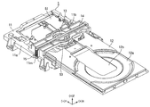
- FIG. 1 is a perspective view showing a state in which a disk tray of a disk device according to Embodiment 1 of the present invention is ejected, as seen from above obliquely;
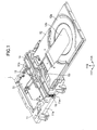
- FIG. 2 is a perspective view showing a state in which the disk tray of the disk device according to Embodiment 1 of the present invention is stored, as seen from above obliquely;
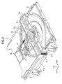
- FIG. 3 is a perspective view showing a state in which a disk clamp mechanism according to Embodiment 1 of the present invention is disassembled, as seen from above obliquely;
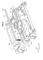
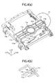
- FIG. 4 ( a ) is a perspective view showing a main chassis of the disk clamp mechanism according to Embodiment 1 of the present invention, as seen from above obliquely;
- FIG. 4 ( b ) is a perspective view showing a supporting portion of a disk clamper pushing member in an enlarged scale
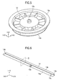
- FIG. 5 is a perspective view showing a disk clamper of the disk clamp mechanism according to Embodiment 1 of the present invention, as seen from above obliquely;
- FIG. 6 is a perspective view showing the disk clamper pushing member of the disk clamp mechanism according to Embodiment 1 of the present invention, as seen from below obliquely;
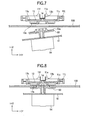
- FIG. 7 is a sectional view showing a state of the main part of the disk clamp mechanism right before the disk clamp mechanism starts a disk clamp operation
- FIG. 8 is a sectional view showing a state of the main part of the disk clamp mechanism having completed the disk clamp operation
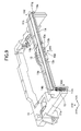
- FIG. 9 is a sectional perspective view showing a state of the main part of the disk clamp mechanism having completed the disk clamp operation
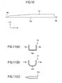
- FIG. 10 is a front view showing a disk clamper pushing member of a disk clamp mechanism according to Embodiment 2 of the present invention.
- FIGS. 11A, 11B and 11 C are perspective views showing a configuration example of a disk clamper pushing member of a disk clamp mechanism according to Embodiment 2 of the present invention.
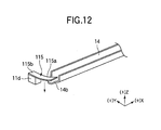
- FIG. 12 is a schematic view showing a configuration for urging in a disk clamp mechanism according to Embodiment 2 of the present invention.
- FIGS. 1 and 2 are perspective views showing the disk device 1 according to Embodiment 1, as seen from above obliquely.
- FIG. 1 shows a state in which a disk tray 12 of the disk device 1 is in a protruding position
- FIG. 2 shows a state in which the disk tray 12 of the disk device 1 is stored.
- the disk device 1 includes a main chassis 11 , a disk tray 12 provided on the main chassis 11 so that the disk tray 12 can be stored in and ejected from the main chassis 11 , and a traverse chassis 51 swingably provided on the main chassis 11 .
- the direction on the same plane as the disk tray 12 i.e., the same plane as a surface of a disk on the disk tray 12
- the direction on the aforementioned plane and perpendicular to the Y direction is defined as the X direction.
- the direction perpendicular to the same plane as the disk tray 12 i.e., the direction perpendicular to the surface of the disk
- the Z direction is defined as the Z direction.
- the Y direction the direction in which the disk tray 12 is stored in the main chassis 11 is defined as +Y direction, and the direction in which the disk tray 12 is ejected from the main chassis 11 is defined as ⁇ Y direction.
- the right direction as viewed facing in the +Y direction is defined as +X direction
- the left direction is defined as ⁇ X direction
- the Z direction the direction from the disk tray 12 toward a disk clamper 13 is defined as +Z direction
- the opposite direction is defined as ⁇ Z direction.
- the main chassis 11 includes a rectangular frame portion 11 a in which the disk tray 12 can be stored, and a disk clamper holding member 11 b which are integrally formed of resin.
- the disk clamper holding member 11 b extends between a pair of opposing side walls of the rectangular frame portion 11 a at the +Z side of the rectangular frame portion 11 a .
- the disk tray 12 is able to pass through between the rectangular frame portion 11 a and the disk clamper holding member 11 b .
- a disk clamper 13 in the form of a circular disk is stored and held at the center portion of the disk clamper holding member 11 b.
- the disk tray 12 is a rectangular plate member that can be stored in the rectangular frame portion 11 a of the main chassis 11 . By the reciprocate movement of the disk tray 12 in the Y direction, the disk tray 12 is stored in or ejected from the rectangular frame portion 11 a of the main chassis 11 .
- a receiving portion 12 a for placing the disk is provided on the surface of the +Z side of the disk tray 12 .
- the disk tray 12 has an opening 12 b that allows access to the disk on the receiving portion 12 a from the ⁇ Z side.
- the traverse chassis 51 is a rectangular plate member having a size such that the traverse chassis 51 can be placed inside the main chassis 11 in XY plane.
- the traverse chassis 51 is supported by the main chassis 11 at a periphery of the +Y side of the traverse chassis 51 so that the traverse chassis 51 is swingable about a swinging axis of the X direction. Further, the traverse chassis 51 swings from the state in which the traverse chassis 51 is parallel to the XY plane ( FIG. 2 ) to the state in which the traverse chassis 51 is inclined with respect to the XY plane toward the ⁇ Z direction ( FIG. 1 ).
- a turntable 53 is mounted on the end portion of the traverse chassis 51 in the ⁇ Y direction.
- an optical pickup unit 52 is supported on the traverse chassis 51 so that the optical pickup unit 52 is movable in the Y direction, and the optical pickup unit 52 records information signal on the disk or reproduce information signal recorded on the disk.
- the turntable 53 moves upward or downward in the Z direction in accordance with the swinging of the traverse chassis 51 . When the turntable 53 is in a raised position, the turntable 53 and the disk clamper 13 clamp the disk and rotate the disk.
- the traverse chassis 51 is in a position where the traverse chassis 51 has swung in the direction away from the disk clamper 13 (i.e., downward). In this state, the traverse chassis 51 is inclined to the ⁇ Z direction with respect to the main chassis 11 , so that the optical pickup unit 52 and the turntable 53 mounted on the traverse chassis 51 do not interfere with the disk to be stored in the disk device 1 .
- the disk tray 12 moves in the +Y direction, and the disk is stored in the main chassis 11 .
- the traverse chassis 51 swings in the +Z direction about the swinging axis, and becomes parallel to the main chassis 11 as shown in FIG. 2 .
- the turntable 53 moves upward and lifts the disk (placed on the receiving portion 12 a of the disk tray 12 ) to clamp the disk between the turntable 53 and the disk clamper 13 .
- the disk clamper 13 is pushed to the turntable 53 side by the disk clamper pushing member 14 as described later.
- the disk clamper 13 , the turntable 53 and the disk clamper pushing member 14 constitute a disk clamp mechanism.
- the turntable 53 rotates, and the disk rotates at a predetermined rotational speed. Further, the optical pickup unit 52 moves in the radial direction of the disk (Y direction in the drawing), and information signal is recorded on a predetermined data area of the disk, or information signal recorded in the disk is reproduced.
- the traverse chassis 51 swings downward ( ⁇ Z direction), so that the optical pickup unit 52 and the turntable 53 shift downward. Then, the disk tray 12 having the receiving portion 12 a on which the disk is placed moves in the ⁇ Y direction, and protrudes to the outside of the disk device 1 as shown in FIG. 1 . With this, the disk is ejected outside the disk device 1 .
- FIG. 3 is an exploded perspective view showing the disk clamp mechanism, as seen from above obliquely.
- FIG. 4 ( a ) is a perspective view showing the main chassis 11 as seen from above obliquely.
- FIG. 4 ( b ) is a perspective view showing a supporting portion for the disk clamper pushing member 14 in an enlarged scale.
- FIG. 5 is a perspective view showing the disk clamper 13 , as seen from above obliquely.
- FIG. 6 is a perspective view showing the disk clamper pushing member 14 , as seen from below obliquely.
- the disk clamp mechanism includes the disk clamper 13 held inside a disk clamper holding portion 11 c of the main chassis 11 and a disk clamper pushing member 14 mounted on the main chassis 11 for pushing the disk clamper 13 in the ⁇ Z direction.
- the disk clamper pushing member 14 is a longitudinal member elongated in the X direction along the above described disk clamper holding member 11 b .
- An end portion (first end portion) 14 a of the disk clamper pushing member 14 is swingably supported by the main chassis 11 as described later.
- the other end portion (second end portion) 14 b of the disk clamper pushing member 14 is linked to a coil spring 15 and is urged in the ⁇ Z direction.
- the main chassis 11 that constitute a base of the disk clamp mechanism includes the above described rectangular frame portion 11 a and a disk clamper holding member 11 b . Both ends of the disk clamper holding member 11 b in the X direction are connected to both side walls of the rectangular frame portion 11 a in the X direction.
- a circular opening (i.e., a disk clamper holding portion 11 c ) for holding the disk clamper 13 is formed on the center portion (in the X direction) of the disk clamper holding member 11 b .
- a groove 11 p extends in the X direction throughout the entire length of the disk clamper holding member 11 b for storing the disk clamper pushing member 14 .
- FIG. 4 ( b ) is an enlarged view showing an end of the disk clamper holding member 11 b , i.e., a part encircled by a circle IV in FIG. 4 ( a ) in an enlarged scale.
- the end portion of the disk clamper holding member 11 b in the +X direction constitutes a protruding portion 11 r that protrudes in the +Z direction.
- a concave portion 11 g that opens to the ⁇ X side and has a predetermined depth is formed on the protruding portion 11 r .
- An end portion 14 a of the disk clamper pushing member 14 is inserted into the concave portion 11 g , and constitutes a swinging fulcrum.
- a boss 11 h is formed adjacent to the concave portion 11 g in the ⁇ X direction.
- the boss 11 h is configured to engage a hole 14 c ( FIG. 6 ) of the disk clamper pushing member 14 when the end portion 14 a of the disk clamper pushing member 14 is inserted into the concave portion 11 g.
- a groove 11 n of the Z direction for holding the coil spring 15 is formed on an end portion of the disk clamper holding member 11 b in the ⁇ X direction. Further, a hook portion 11 m is formed below the groove 11 n at the end portion of the disk clamper holding member 11 b in the ⁇ X direction, and the hook portion 11 m engages an end of the coil spring 15 .
- the groove 11 p of the X direction provided on the disk clamper holding member 11 b has a width approximately the same as or wider than the width of the base surface of the disk clamper pushing member 14 , and stores the disk clamper pushing member 14 therein.
- the guide portions 11 e and 11 f in the form of projections are formed on both side surfaces of the groove 11 p , and have the heights higher than the side surfaces of the groove 11 p in the Z direction.
- the guide portions 11 e and 11 f protrude inwardly from the side surfaces of the groove 11 p , and are able to contact the side surfaces of the disk clamper holding member 14 .
- the guide portions 11 e and 11 f define the swinging of the disk clamper holding member 14 in the XY plane about the boss 11 h .
- the disk clamper pushing member 14 is not swingable in the XY plane but is swingable only in the XZ plane.
- the disk clamper 13 is in the form of a circular disk.
- a contact surface 13 a is formed on a side of the disk clamper 13 facing the turntable 53 .
- a hemispheric convex portion 13 b is formed on the center in the radial direction of the disk clamper 13 , and a flange portion 13 c is formed to protrude outwardly from the periphery of the above described contact surface 13 a.
- the disk clamper 13 is stored in the inside of the disk clamper holding portion 11 c ( FIG. 3 ) formed on the disk clamper holding member 11 b .
- the flange portion 13 c of the disk clamper 13 is supported by a bottom portion 11 j ( FIG. 7 ) of the disk clamper holding portion 11 c from below.
- the bottom portion 11 j of the disk clamper holding portion 11 c abuts against the flange portion 13 c to lift the disk clamper 13 upward in the +Z direction, and supports the disk clamper 13 on the upper side (+Z side) with respect to the moving path of the disk tray 12 and the disk. With this, the interference of the disk clamper 13 with the disk tray 12 and the disk that reciprocally move in the Y direction can be prevented.
- the disk clamper pushing member 14 shown in FIG. 6 is formed of a metal plate having the thickness of 0.4 mm and has a length (the dimension in the X direction) approximately the same as the disk clamper holding member 11 b .
- the disk clamper pushing member 14 has an elongated bottom plate 14 g having the width of approximately 3 mm, and a pair of side plates 14 e and 14 f formed on both sides of the bottom plate 14 g (one side wall 14 f is omitted in FIG. 6 ).
- the heights (the dimension in the Z direction) of the side plates 14 e and 14 f are approximately 3 mm.
- the end portion 14 a of the disk clamper pushing member 14 in the +X direction is inserted into the concave portion 11 g ( FIG.
- the hole 14 c is formed in the vicinity of the end portion 14 a of the disk clamper pushing member 14 .
- the hole 14 c fits the boss 11 h of the main chassis 11 , and the side plates 14 e and 14 f are placed in between the guide portions 11 e and 11 f of the main chassis 11 .
- the disk clamper pushing member 14 becomes swingable only in the XZ plane.
- the end portion 14 b of the disk clamper pushing member 14 in the ⁇ X direction is fixed to an end of the coil spring 15 opposite to the end fixed to the hook portion 11 m of the main chassis 11 , and is urged in the ⁇ Z direction.
- a pushing surface 14 d is formed at the center of the disk clamper pushing member 14 , and the pushing surface 14 d abuts and pushes downward the convex portion 13 b ( FIG. 5 ) of the disk clamper 13 .
- FIG. 7 shows a state after the disk tray 12 is stored in the main chassis 11 and right before the turntable 53 starts moving upward.
- the traverse chassis 51 is inclined, and the turntable 53 is held at a position lower than the feeding path of the disk 100 placed on the disk tray 12 (omitted in FIG. 7 ).
- the flange portion 13 c is lifted upward by the bottom portion 11 j of the disk clamper holding portion 11 c , so that the disk clamper 13 is held at a position higher than the feeding path of the disk 100 .
- the convex portion 13 b of the disk clamper 13 contacts the pushing surface 14 d ( FIG. 6 ) of the disk clamper pushing member 14 , and the end portion 14 b ( FIG. 3 ) of the disk clamper pushing member 14 is urged by the coil spring 15 in the ⁇ Z direction, with the result that the disk clamper 13 is pushed in the ⁇ Z direction.
- a placing surface 53 a of the turntable 53 contacts the disk 100 to lift the disk 100 from the disk tray 12 , so that the disk 100 is held on the placing surface 53 a of the turntable 53 .
- the turntable 53 moves further upward, the disk 100 abuts against the contact surface 13 a of the disk clamper 13 , so that the disk clamper 13 moves upward together with the disk 100 .
- the flange portion 13 c of the disk clamper 13 moves upward away from the bottom portion 11 j of the disk clamper holding portion 11 c .
- the disk clamper 13 is pushed to the turntable 53 side (in the ⁇ Z direction) by the disk clamper pushing member 14 , and therefore the disk 100 is clamped between the disk clamper 13 and the turntable 53 and is held therebetween.
- FIG. 8 shows a state where the upward movement of the turntable 53 is completed.
- the traverse chassis 51 and the turntable 53 are in horizontal state (i.e., the rotational axis of the turntable 53 is oriented in the vertical direction).
- a predetermined gap S is formed between the disk clamper 13 and the bottom portion 11 j of the disk clamper holding portion 11 c . Then, the disk 100 is rotated together with the turntable 53 by the spindle motor 54 , and the recording or reproducing of the information signal is performed on the disk.
- FIG. 9 is a perspective view showing the disk clamp mechanism when the disk clamp operation is completed, cut along a XZ plane.
- the dimension and the spring coefficient of the coil spring 15 is so determined as to generate a force of 1N in the ⁇ Z direction in a state where the disk 100 is clamped between the disk clamper 13 and the turntable 53 (i.e., during the disk clamp operation). Therefore, the force of 1N is applied to either of the end portions 14 a and 14 b of the disk clamper pushing member 14 . In contrast, by the upward movement of the turntable 53 ( FIG. 8 ), the force is applied to the pushing surface 14 d of the disk clamper pushing member 14 as shown by an arrow in the drawing, and the magnitude of the force is double the resilient force of the coil spring 15 , i.e., 2N.
- the disk clamper pushing member 14 is applied with the force during the disk clamp operation as described above, the disk clamper pushing member 14 is fixed to the connecting portions of the rectangular frame portion 11 a and the disk clamper holding member 11 b , and therefore a force causing a deformation (curving) of the disk clamper holding member 11 b is not generated. Accordingly, even when the disk device is left under the high temperature environment, the creep deformation of the disk clamper holding member 11 b does not occur.
- the main chassis 11 is applied with a force in the direction opposite to the force applied to both end portions 14 a and 14 b of the disk clamper pushing member 14 .
- the concave portion 11 g of the main chassis 11 is applied with the force of 1N in the ⁇ Z direction
- the hook portion 11 m of the main chassis 11 is applied with the force of 1N in the +Z direction.
- This force is such that the side walls of the rectangular frame portion 11 a at the ends in the +X direction and ⁇ X direction are curved in the YZ plane.
- the thickness of the side walls of the rectangular frame portion 11 a has no influence on the reduction of thickness of the disk device, and therefore the side walls can be sufficiently thick so as to prevent the creep deformation. Accordingly, the creep deformation of the main chassis 11 does not occur.
- the end portions 14 a and 14 b and the pushing surface 14 d of the disk clamper pushing member 14 are applied with the forces in the directions in which the disk clamper pushing member 14 is curved in the Z direction.
- the disk clamper pushing member 14 has a rectangular U-shape with the height (dimension in the Z direction) of 3 mm that provides a rib effect, and therefore the disk clamper pushing member 14 has a sufficient rigidity against the deformation (curving) due to the coil spring 15 . Accordingly, the deformation of the disk clamper pushing member 14 does not occur.
- the end portion 14 a of the disk clamper pushing member 14 is swingably supported at the side wall of the +X side of the main chassis 11 , and the other end 14 b of the disk clamper pushing member 14 is urged in the ⁇ Z direction at the side wall of the ⁇ X side of the main chassis 11 . Therefore, it becomes possible to prevent the generation of the force that causes the curvature of the disk clamper holding member 11 b . Accordingly, even when the disk device is left under the high temperature environment, no deformation occurs on the disk clamper holding member 11 b , the main chassis 11 or the disk clamper pushing member 14 . That is, it becomes possible to obtain the disk clamp mechanism having high reliability and capable of surely clamping the disk onto the turntable 53 .
- the force causing the deformation (curving) of the disk clamper holding member 11 b does not occur, it is not necessary to thicken the disk clamper holding member 11 b to enhance the rigidity of the disk clamper holding member 11 b to thereby restrict the bending stress.
- the creep deformation can be prevented by increasing the thickness in the direction other than the Z direction.
- the strength of the main chassis 11 can be ensured without increasing the height in the +Z direction, and therefore the disk clamp mechanism having the same size as or a smaller size than the conventional disk clamp mechanism can be accomplished. As a result, the disk device having the same size as or a smaller size than the conventional disk device can be obtained.
- a spring stainless steel band which is a general material of a plate spring disclosed in the Patent Publication No. 1 is expensive, and is hard to obtain since an exclusive mold is required to manufacture the spring stainless steel band.
- this Embodiment 1 uses the disk clamper pushing member 14 and the coil spring 15 instead of the plate spring for pushing the disk clamper 13 against the turntable 53 , and therefore it becomes possible to obtain an inexpensive disk clamp mechanism.
- the coil spring 15 can be obtained at the cost of approximately one fifth of the plate spring.
- the disk clamper pushing member 14 is formed of a metal thin plate having the thickness of 0.4 mm, the disk clamper pushing member 14 can be obtained at a cost of approximately 2.5 times the coil spring.
- the plate spring by replacing the plate spring with the disk clamper pushing member 14 and the coil spring 15 , it becomes possible to reduce the cost corresponding to one and half of the coil spring 15 . Further, unlike the plate spring, the coil spring 15 does not need an exclusive mold, and therefore the coil spring 15 can easily be obtained.
- the disk clamper pushing member 14 is urged by the coil spring 15 provided between the end portion 14 b and the hook portion 11 m of the main chassis 11 , and therefore the configuration for urging the disk clamper 14 in the ⁇ Z direction can be simple.
- FIG. 10 is a front view showing a side portion of the disk clamper pushing member 14 of the disk device 1 according to Embodiment 2, as seen from the +Y side.
- the height (dimension in the Z direction) of the disk clamper pushing member 14 is constant (see FIGS. 2 and 3 ).
- the height of the disk clamper pushing member 14 decreases, from the center portion to the end portion 14 b.
- the height (dimension in the Z direction) of the disk clamper pushing member 14 gradually decreases, from the center portion of the disk clamper pushing member 14 to the end portion 14 b in the ⁇ X direction.
- the height of the disk clamper pushing member 14 is constant, from the center portion of the disk clamper pushing member 14 to the end portion 14 a in the +X direction (the portion attached to the main chassis 11 as the swinging fulcrum).
- the disk clamper pushing member 14 swings in the +Z direction about the end portion 14 a in the +X direction, and therefore the shifting amount in the +Z direction increases as approaching the end portion 14 b in the ⁇ X direction.
- the height of the disk clamper pushing member 14 decreases as approaching the end portion 14 b in the ⁇ X direction, and therefore protruding amount of the disk clamper pushing member 14 in the +Z direction can be reduced.
- the dimension of the disk clamp mechanism in the +Z direction can be reduced, so that a thinner disk device can be accomplished.
- the force applied to the substance is the largest at the point of action and decreases as receding from the point of action. Therefore, the force applied to the disk clamper pushing member 14 by the disk clamper 13 is the largest at the pushing surface 14 d (for example, 2N) and decreases as approaching the end portion 14 a or 14 b (for example, 1N). Accordingly, even when the disk clamper pushing member 14 is so configured that the height thereof decreases from the center portion to the end portion 14 b , the disk clamper pushing member 14 can sufficiently tolerate the force of deforming (curving) the disk clamper pushing member 14 .
- the height (the dimension in Z direction) of the disk clamper pushing member 14 gradually decreases from the center portion to the end portion 14 b in the ⁇ X direction, and therefore the protruding amount of the disk clamper pushing member 14 in the +Z direction can be reduced.
- the disk clamp mechanism can be thinned while maintaining the force of clamping the disk, so that a thinner disk device can be accomplished.
- FIGS. 11A through 11C are sectional views showing the sectional shapes of the disk clamper pushing member according to this embodiment, compared with the sectional shape ( FIG. 11A ) of the disk clamper pushing member 14 according to the above described Embodiment 1.
- FIG. 11A through 11C correspond to a section cut along a surface XI (YZ plane) shown in FIG. 6 .
- the disk clamper pushing member 14 of the above described Embodiment 1 has a rectangular U-shaped section for ensuring the strength as shown in FIG. 11A
- the strength can be ensured even when the disk clamper pushing member has other sectional shape.
- the disk clamper pushing member 114 shown in FIG. 11B has a U-shaped section instead of the rectangular U-shaped section.
- the disk clamper pushing member 114 includes, in the YZ plane, a pair of opposing side plate portions 114 a and 114 b and a bottom plate portion 114 c curved in the ⁇ Z direction.
- the disk clamper pushing member 114 is formed of a flat plate member (or a flat plate member around which a thin sheet metal is wound) as shown in FIG. 11C , it is only necessary that the disk clamper pushing member 114 has a thickness T (the dimension in the Z direction) sufficient for tolerate the force applied by the disk clamper 13 .
- FIG. 12 is a perspective view showing an example of a configuration for urging the disk clamper pushing member 14 in Embodiment 4.
- the end portion 14 b of the disk clamper pushing member 14 is urged in the ⁇ Z direction using the coil spring 15 ( FIG. 3 )
- a plate spring 115 is used.
- an end 115 a of the plate spring 115 in the longitudinal direction is fixed to a fixing member 11 d provided on the main chassis 11 , and the other end 115 b urges the end portion 14 b of the disk clamper pushing member 14 in the ⁇ Z direction.
- the urging of the disk clamper pushing member 14 using the plate spring or flat spiral spring can be performed by other methods, as long as a sufficient force for clamping the disk is obtained.
Abstract
Description
- This invention relates to a disk clamp mechanism for holding a disk as an information recording medium such as, for example, a compact disk (CD) and a digital versatile disk (DVD) or the like, and also relates to a disk device using the disk clamp mechanism.
- A disk device such as a DVD player or the like is configured to perform recording and reproducing of information signal while rotating a disk as an information recording medium using a turntable. A disk clamp mechanism is used to clamp the disk onto the turntable to hold the disk. There is known a disk clamp mechanism (of the first type) configured to push the disk clamper to the turntable side using the resilient force of a plate spring (see, for example, Patent Publication No. 1). There is known another disk clamp mechanism (of the second type) configured to attract the disk clamper to the turntable using a magnet or a magnetic body (see, for example, Patent Publication No. 2).
- Patent Publication No. 1: Japanese Patent Publication No. 2680727 (Page 3, FIG. 2).
- Patent Publication No. 2: Japanese Laid-Open Patent Publication No. 2003-123353 (Pages 3-4, FIG. 2).
- In the disk clamp mechanism of the first type, a movable base on which the turntable is mounted is swingably (movably in the vertical direction) provided on a main chassis. The disk clamper is held by a disk clamper holding member formed of a metal plate having the thickness of 1 mm, and is pushed to the turntable side by the plate spring provided on an upper surface (i.e., a surface opposite to the turntable) of the disk clamper holding member. When the turntable moves upward by the swinging of the movable base, the disk clamper is pushed to the turntable side by means of the compression force of the plate spring, so that the disk is clamped between the disk clamper and the turntable.
- In the disk clamp mechanism of the second type, the magnet is fixed to the turntable instead of the plate spring. The magnet magnetically attracts the turntable, so that the disk is clamped between the disk clamper and the turntable. Further, the main chassis and the disk clamper holding member are integrally formed of resin.
- In either of the disk clamp mechanisms of the first and second types, the force for clamping the disk is approximately 2N (Newton) in general.
- However, the plate metal used as the disk clamper holding member in the disk clamp mechanism of the first type is an expensive material. Further, the magnet or the like used in the disk clamp mechanism of the second type is also an expensive material. Therefore, in terms of the reduction of the manufacturing cost, it is demanded to develop the disk clamp mechanism that does not use such expensive materials.
- In this case, it is considered to use the plate spring for forcing the disk clamper, and to integrally form the disk clamper holding member and the main chassis using resin. However, with such a configuration, the urging force of the plate spring is applied to a portion for mounting the plate spring of the disk clamper holding member as a reactive force. Therefore, in the case where the disk device is placed under high temperature environment, there is a possibility that the disk clamper holding member may curve in the direction away from the turntable due to creep deformation. In this case, the distance between the plate spring and the turntable may increase.
- When the distance between the plate spring and the turntable increases, the compressing amount of the plate spring (during the recording or reproducing) decreases, and therefore the urging force with which the disk clamper clamps the disk onto the turntable becomes insufficient. As a result, there arises a problem that a slip between the turntable and the disk may occur to cause trouble in the recording or reproducing function, or to cause the disk to be dropped out of the turntable.
- The present invention is intended to solve the above problems, and an object of the present invention is to prevent the creep deformation of the disk clamper holding member to thereby ensure the clamping of the disk onto the turntable.
- A disk clamp mechanism of the present invention includes a disk clamper, a main chassis, a disk clamper pushing member and a resilient member. The disk clamper is provided in opposition to a turntable, has a contact surface contacting a disk on a side facing the turntable, and has a convex portion on a side opposite to the contact surface. The main chassis includes a frame body and a disk clamper holding member provided on the frame body for holding the disk clamper. The disk clamper pushing member has a pushing surface that pushes the convex portion of the disk clamper toward the disk and first and second end portions provided on both sides of the pushing surface. The first end portion is swingably supported by the main chassis, and the pushing surface is swingable in a direction perpendicular to a surface of the disk. The resilient member urges the second end portion of the disk clamper pushing member in the direction in which the pushing surface pushes the disk.
- According to the present invention, the first end portion of the disk clamper pushing member is swingably supported by the main chassis, and the second end portion is urged toward the turntable by means of the resilient member. Therefore, the disk clamp operation does not cause the creep deformation of a part of the disk clamper holding member. As a result, it becomes possible to accomplish the disk clamp mechanism capable of surely clamping the disk onto the turntable.
-
FIG. 1 is a perspective view showing a state in which a disk tray of a disk device according toEmbodiment 1 of the present invention is ejected, as seen from above obliquely; -
FIG. 2 is a perspective view showing a state in which the disk tray of the disk device according toEmbodiment 1 of the present invention is stored, as seen from above obliquely; -
FIG. 3 is a perspective view showing a state in which a disk clamp mechanism according toEmbodiment 1 of the present invention is disassembled, as seen from above obliquely; -
FIG. 4 (a) is a perspective view showing a main chassis of the disk clamp mechanism according toEmbodiment 1 of the present invention, as seen from above obliquely; -
FIG. 4 (b) is a perspective view showing a supporting portion of a disk clamper pushing member in an enlarged scale; -
FIG. 5 is a perspective view showing a disk clamper of the disk clamp mechanism according toEmbodiment 1 of the present invention, as seen from above obliquely; -
FIG. 6 is a perspective view showing the disk clamper pushing member of the disk clamp mechanism according toEmbodiment 1 of the present invention, as seen from below obliquely; -
FIG. 7 is a sectional view showing a state of the main part of the disk clamp mechanism right before the disk clamp mechanism starts a disk clamp operation; -
FIG. 8 is a sectional view showing a state of the main part of the disk clamp mechanism having completed the disk clamp operation; -
FIG. 9 is a sectional perspective view showing a state of the main part of the disk clamp mechanism having completed the disk clamp operation; -
FIG. 10 is a front view showing a disk clamper pushing member of a disk clamp mechanism according toEmbodiment 2 of the present invention; -
FIGS. 11A, 11B and 11C are perspective views showing a configuration example of a disk clamper pushing member of a disk clamp mechanism according toEmbodiment 2 of the present invention, and -
FIG. 12 is a schematic view showing a configuration for urging in a disk clamp mechanism according toEmbodiment 2 of the present invention. - 1 . . . disk device, 11 . . . main chassis, 11 a . . . rectangular frame portion, 11 b . . . disk clamper holding member, 13 . . . disk clamper, 13 a . . . contact surface, 13 b . . . convex portion, 14 . . . disk clamper pushing member, 15 . . . coil spring.
- First, the configuration and operation of a DVD player device (hereinafter, a disk device) in which a disk clamp mechanism according to
Embodiment 1 of the present invention is mounted will be described. -
FIGS. 1 and 2 are perspective views showing thedisk device 1 according toEmbodiment 1, as seen from above obliquely. In this regard,FIG. 1 shows a state in which adisk tray 12 of thedisk device 1 is in a protruding position, andFIG. 2 shows a state in which the disk tray 12 of thedisk device 1 is stored. - As shown in
FIG. 1 , thedisk device 1 includes amain chassis 11, adisk tray 12 provided on themain chassis 11 so that thedisk tray 12 can be stored in and ejected from themain chassis 11, and atraverse chassis 51 swingably provided on themain chassis 11. - Here, for convenience of explanation, the direction on the same plane as the disk tray 12 (i.e., the same plane as a surface of a disk on the disk tray 12) and parallel to the direction of storage/ejection of the
disk tray 12 is defined as the Y direction. The direction on the aforementioned plane and perpendicular to the Y direction is defined as the X direction. The direction perpendicular to the same plane as the disk tray 12 (i.e., the direction perpendicular to the surface of the disk) is defined as the Z direction. With regard to the Y direction, the direction in which thedisk tray 12 is stored in themain chassis 11 is defined as +Y direction, and the direction in which thedisk tray 12 is ejected from themain chassis 11 is defined as −Y direction. With regard to the X direction, the right direction as viewed facing in the +Y direction is defined as +X direction, and the left direction is defined as −X direction. With regard to the Z direction, the direction from thedisk tray 12 toward adisk clamper 13 is defined as +Z direction, the opposite direction is defined as −Z direction. - The
main chassis 11 includes arectangular frame portion 11 a in which thedisk tray 12 can be stored, and a diskclamper holding member 11 b which are integrally formed of resin. The diskclamper holding member 11 b extends between a pair of opposing side walls of therectangular frame portion 11 a at the +Z side of therectangular frame portion 11 a. Thedisk tray 12 is able to pass through between therectangular frame portion 11 a and the diskclamper holding member 11 b. Adisk clamper 13 in the form of a circular disk is stored and held at the center portion of the diskclamper holding member 11 b. - The
disk tray 12 is a rectangular plate member that can be stored in therectangular frame portion 11 a of themain chassis 11. By the reciprocate movement of thedisk tray 12 in the Y direction, thedisk tray 12 is stored in or ejected from therectangular frame portion 11 a of themain chassis 11. A receivingportion 12 a for placing the disk is provided on the surface of the +Z side of thedisk tray 12. Thedisk tray 12 has anopening 12 b that allows access to the disk on the receivingportion 12 a from the −Z side. - As shown in
FIGS. 1 and 2 , thetraverse chassis 51 is a rectangular plate member having a size such that thetraverse chassis 51 can be placed inside themain chassis 11 in XY plane. Thetraverse chassis 51 is supported by themain chassis 11 at a periphery of the +Y side of thetraverse chassis 51 so that thetraverse chassis 51 is swingable about a swinging axis of the X direction. Further, thetraverse chassis 51 swings from the state in which thetraverse chassis 51 is parallel to the XY plane (FIG. 2 ) to the state in which thetraverse chassis 51 is inclined with respect to the XY plane toward the −Z direction (FIG. 1 ). Aturntable 53 is mounted on the end portion of thetraverse chassis 51 in the −Y direction. Further, anoptical pickup unit 52 is supported on thetraverse chassis 51 so that theoptical pickup unit 52 is movable in the Y direction, and theoptical pickup unit 52 records information signal on the disk or reproduce information signal recorded on the disk. Theturntable 53 moves upward or downward in the Z direction in accordance with the swinging of thetraverse chassis 51. When theturntable 53 is in a raised position, theturntable 53 and thedisk clamper 13 clamp the disk and rotate the disk. - Next, the entire operation of the
disk device 1 will be described. As shown inFIG. 1 , when thedisk tray 12 protrudes outside themain chassis 11, thetraverse chassis 51 is in a position where thetraverse chassis 51 has swung in the direction away from the disk clamper 13 (i.e., downward). In this state, thetraverse chassis 51 is inclined to the −Z direction with respect to themain chassis 11, so that theoptical pickup unit 52 and theturntable 53 mounted on thetraverse chassis 51 do not interfere with the disk to be stored in thedisk device 1. - After the disk (not shown) is placed on the receiving
portion 12 a of thedisk tray 12, thedisk tray 12 moves in the +Y direction, and the disk is stored in themain chassis 11. When the disk placed on the receivingportion 12 a reaches the position right above theturntable 53, thetraverse chassis 51 swings in the +Z direction about the swinging axis, and becomes parallel to themain chassis 11 as shown inFIG. 2 . - As the
traverse chassis 51 become parallel to themain chassis 11, theturntable 53 moves upward and lifts the disk (placed on the receivingportion 12 a of the disk tray 12) to clamp the disk between theturntable 53 and thedisk clamper 13. Thedisk clamper 13 is pushed to theturntable 53 side by the diskclamper pushing member 14 as described later. Thedisk clamper 13, theturntable 53 and the diskclamper pushing member 14 constitute a disk clamp mechanism. - In this state, the
turntable 53 rotates, and the disk rotates at a predetermined rotational speed. Further, theoptical pickup unit 52 moves in the radial direction of the disk (Y direction in the drawing), and information signal is recorded on a predetermined data area of the disk, or information signal recorded in the disk is reproduced. - After the recording or reproducing of the information signal is completed, the
traverse chassis 51 swings downward (−Z direction), so that theoptical pickup unit 52 and theturntable 53 shift downward. Then, thedisk tray 12 having the receivingportion 12 a on which the disk is placed moves in the −Y direction, and protrudes to the outside of thedisk device 1 as shown inFIG. 1 . With this, the disk is ejected outside thedisk device 1. - Next, the disk clamp mechanism according to
Embodiment 1 will be described in detail. -
FIG. 3 is an exploded perspective view showing the disk clamp mechanism, as seen from above obliquely.FIG. 4 (a) is a perspective view showing themain chassis 11 as seen from above obliquely.FIG. 4 (b) is a perspective view showing a supporting portion for the diskclamper pushing member 14 in an enlarged scale.FIG. 5 is a perspective view showing thedisk clamper 13, as seen from above obliquely.FIG. 6 is a perspective view showing the diskclamper pushing member 14, as seen from below obliquely. - As shown in
FIG. 3 , the disk clamp mechanism includes thedisk clamper 13 held inside a diskclamper holding portion 11 c of themain chassis 11 and a diskclamper pushing member 14 mounted on themain chassis 11 for pushing thedisk clamper 13 in the −Z direction. - The disk
clamper pushing member 14 is a longitudinal member elongated in the X direction along the above described diskclamper holding member 11 b. An end portion (first end portion) 14 a of the diskclamper pushing member 14 is swingably supported by themain chassis 11 as described later. The other end portion (second end portion) 14 b of the diskclamper pushing member 14 is linked to acoil spring 15 and is urged in the −Z direction. - As shown in
FIG. 4 (a), themain chassis 11 that constitute a base of the disk clamp mechanism includes the above describedrectangular frame portion 11 a and a diskclamper holding member 11 b. Both ends of the diskclamper holding member 11 b in the X direction are connected to both side walls of therectangular frame portion 11 a in the X direction. A circular opening (i.e., a diskclamper holding portion 11 c) for holding thedisk clamper 13 is formed on the center portion (in the X direction) of the diskclamper holding member 11 b. Agroove 11 p extends in the X direction throughout the entire length of the diskclamper holding member 11 b for storing the diskclamper pushing member 14. -
FIG. 4 (b) is an enlarged view showing an end of the diskclamper holding member 11 b, i.e., a part encircled by a circle IV inFIG. 4 (a) in an enlarged scale. The end portion of the diskclamper holding member 11 b in the +X direction constitutes a protrudingportion 11 r that protrudes in the +Z direction. Aconcave portion 11 g that opens to the −X side and has a predetermined depth is formed on the protrudingportion 11 r. Anend portion 14 a of the diskclamper pushing member 14 is inserted into theconcave portion 11 g, and constitutes a swinging fulcrum. Inside thegroove 11 p, aboss 11 h is formed adjacent to theconcave portion 11 g in the −X direction. Theboss 11 h is configured to engage ahole 14 c (FIG. 6 ) of the diskclamper pushing member 14 when theend portion 14 a of the diskclamper pushing member 14 is inserted into theconcave portion 11 g. - As shown in
FIG. 3 , agroove 11 n of the Z direction for holding thecoil spring 15 is formed on an end portion of the diskclamper holding member 11 b in the −X direction. Further, ahook portion 11 m is formed below thegroove 11 n at the end portion of the diskclamper holding member 11 b in the −X direction, and thehook portion 11 m engages an end of thecoil spring 15. - The
groove 11 p of the X direction provided on the diskclamper holding member 11 b has a width approximately the same as or wider than the width of the base surface of the diskclamper pushing member 14, and stores the diskclamper pushing member 14 therein. Theguide portions groove 11 p, and have the heights higher than the side surfaces of thegroove 11 p in the Z direction. Theguide portions groove 11 p, and are able to contact the side surfaces of the diskclamper holding member 14. Theguide portions clamper holding member 14 in the XY plane about theboss 11 h. In other words, the diskclamper pushing member 14 is not swingable in the XY plane but is swingable only in the XZ plane. - As shown in
FIG. 5 , thedisk clamper 13 is in the form of a circular disk. Acontact surface 13 a is formed on a side of thedisk clamper 13 facing theturntable 53. On a side of thedisk clamper 13 opposite to theturntable 53, a hemisphericconvex portion 13 b is formed on the center in the radial direction of thedisk clamper 13, and aflange portion 13 c is formed to protrude outwardly from the periphery of the above describedcontact surface 13 a. - The
disk clamper 13 is stored in the inside of the diskclamper holding portion 11 c (FIG. 3 ) formed on the diskclamper holding member 11 b. Theflange portion 13 c of thedisk clamper 13 is supported by abottom portion 11 j (FIG. 7 ) of the diskclamper holding portion 11 c from below. On the storage/ejection of thedisk tray 12, thebottom portion 11 j of the diskclamper holding portion 11 c abuts against theflange portion 13 c to lift thedisk clamper 13 upward in the +Z direction, and supports thedisk clamper 13 on the upper side (+Z side) with respect to the moving path of thedisk tray 12 and the disk. With this, the interference of thedisk clamper 13 with thedisk tray 12 and the disk that reciprocally move in the Y direction can be prevented. - The disk
clamper pushing member 14 shown inFIG. 6 is formed of a metal plate having the thickness of 0.4 mm and has a length (the dimension in the X direction) approximately the same as the diskclamper holding member 11 b. The diskclamper pushing member 14 has an elongatedbottom plate 14 g having the width of approximately 3 mm, and a pair ofside plates bottom plate 14 g (oneside wall 14 f is omitted inFIG. 6 ). The heights (the dimension in the Z direction) of theside plates end portion 14 a of the diskclamper pushing member 14 in the +X direction is inserted into theconcave portion 11 g (FIG. 4 ) of the above describedmain chassis 11. Thehole 14 c is formed in the vicinity of theend portion 14 a of the diskclamper pushing member 14. In a state where theend portion 14 a of the diskclamper pushing member 14 is inserted in theconcave portion 11 g (FIG. 4 ) of themain chassis 11, thehole 14 c fits theboss 11 h of themain chassis 11, and theside plates guide portions main chassis 11. With this, the diskclamper pushing member 14 becomes swingable only in the XZ plane. Theend portion 14 b of the diskclamper pushing member 14 in the −X direction is fixed to an end of thecoil spring 15 opposite to the end fixed to thehook portion 11 m of themain chassis 11, and is urged in the −Z direction. A pushingsurface 14 d is formed at the center of the diskclamper pushing member 14, and the pushingsurface 14 d abuts and pushes downward theconvex portion 13 b (FIG. 5 ) of thedisk clamper 13. - Next, the detailed operation of the disk clamp mechanism as configured above will be described.
-
FIG. 7 shows a state after thedisk tray 12 is stored in themain chassis 11 and right before theturntable 53 starts moving upward. In this state, thetraverse chassis 51 is inclined, and theturntable 53 is held at a position lower than the feeding path of thedisk 100 placed on the disk tray 12 (omitted inFIG. 7 ). - The
flange portion 13 c is lifted upward by thebottom portion 11 j of the diskclamper holding portion 11 c, so that thedisk clamper 13 is held at a position higher than the feeding path of thedisk 100. In this state, theconvex portion 13 b of thedisk clamper 13 contacts the pushingsurface 14 d (FIG. 6 ) of the diskclamper pushing member 14, and theend portion 14 b (FIG. 3 ) of the diskclamper pushing member 14 is urged by thecoil spring 15 in the −Z direction, with the result that thedisk clamper 13 is pushed in the −Z direction. - When the
traverse chassis 51 swings upward and theturntable 53 moves upward, a placingsurface 53 a of theturntable 53 contacts thedisk 100 to lift thedisk 100 from thedisk tray 12, so that thedisk 100 is held on the placingsurface 53 a of theturntable 53. When theturntable 53 moves further upward, thedisk 100 abuts against thecontact surface 13 a of thedisk clamper 13, so that thedisk clamper 13 moves upward together with thedisk 100. In other words, theflange portion 13 c of thedisk clamper 13 moves upward away from thebottom portion 11 j of the diskclamper holding portion 11 c. Further, thedisk clamper 13 is pushed to theturntable 53 side (in the −Z direction) by the diskclamper pushing member 14, and therefore thedisk 100 is clamped between thedisk clamper 13 and theturntable 53 and is held therebetween. -
FIG. 8 shows a state where the upward movement of theturntable 53 is completed. In this state, thetraverse chassis 51 and theturntable 53 are in horizontal state (i.e., the rotational axis of theturntable 53 is oriented in the vertical direction). Further, a predetermined gap S is formed between thedisk clamper 13 and thebottom portion 11 j of the diskclamper holding portion 11 c. Then, thedisk 100 is rotated together with theturntable 53 by thespindle motor 54, and the recording or reproducing of the information signal is performed on the disk. - Next, the disk clamp action of the disk clamp mechanism will be described in further detail.
FIG. 9 is a perspective view showing the disk clamp mechanism when the disk clamp operation is completed, cut along a XZ plane. - When the
disk clamper 13 moves upward together with theturntable 53, the diskclamper pushing member 14 contacting thedisk clamper 13 is lifted by the diskclamper pushing member 14 in the +Z direction. As a result, the diskclamper pushing member 14 swings about theend portion 14 a in the X direction so that theother end portion 14 b shifts in the +Z direction. Therefore, thecoil spring 15 fixed to theother end portion 14 b of the diskclamper pushing member 14 is stretched. - The dimension and the spring coefficient of the
coil spring 15 is so determined as to generate a force of 1N in the −Z direction in a state where thedisk 100 is clamped between thedisk clamper 13 and the turntable 53 (i.e., during the disk clamp operation). Therefore, the force of 1N is applied to either of theend portions clamper pushing member 14. In contrast, by the upward movement of the turntable 53 (FIG. 8 ), the force is applied to the pushingsurface 14 d of the diskclamper pushing member 14 as shown by an arrow in the drawing, and the magnitude of the force is double the resilient force of thecoil spring 15, i.e., 2N. The forces applied to bothend portions clamper pushing member 14 and the force applied to the pushingsurface 14 d are balanced. Thus, thedisk 100 is clamped between the disk clamper 13 (pushed by the disk clamper pushing member 14) and theturntable 53 with the force of 2N and held therebetween. - Although the disk
clamper pushing member 14 is applied with the force during the disk clamp operation as described above, the diskclamper pushing member 14 is fixed to the connecting portions of therectangular frame portion 11 a and the diskclamper holding member 11 b, and therefore a force causing a deformation (curving) of the diskclamper holding member 11 b is not generated. Accordingly, even when the disk device is left under the high temperature environment, the creep deformation of the diskclamper holding member 11 b does not occur. - In contrast, the
main chassis 11 is applied with a force in the direction opposite to the force applied to bothend portions clamper pushing member 14. In other words, theconcave portion 11 g of themain chassis 11 is applied with the force of 1N in the −Z direction, and thehook portion 11 m of themain chassis 11 is applied with the force of 1N in the +Z direction. This force is such that the side walls of therectangular frame portion 11 a at the ends in the +X direction and −X direction are curved in the YZ plane. However, the thickness of the side walls of therectangular frame portion 11 a has no influence on the reduction of thickness of the disk device, and therefore the side walls can be sufficiently thick so as to prevent the creep deformation. Accordingly, the creep deformation of themain chassis 11 does not occur. - Further, the
end portions surface 14 d of the diskclamper pushing member 14 are applied with the forces in the directions in which the diskclamper pushing member 14 is curved in the Z direction. However, the diskclamper pushing member 14 has a rectangular U-shape with the height (dimension in the Z direction) of 3 mm that provides a rib effect, and therefore the diskclamper pushing member 14 has a sufficient rigidity against the deformation (curving) due to thecoil spring 15. Accordingly, the deformation of the diskclamper pushing member 14 does not occur. - As described above, according to
Embodiment 1, theend portion 14 a of the diskclamper pushing member 14 is swingably supported at the side wall of the +X side of themain chassis 11, and theother end 14 b of the diskclamper pushing member 14 is urged in the −Z direction at the side wall of the −X side of themain chassis 11. Therefore, it becomes possible to prevent the generation of the force that causes the curvature of the diskclamper holding member 11 b. Accordingly, even when the disk device is left under the high temperature environment, no deformation occurs on the diskclamper holding member 11 b, themain chassis 11 or the diskclamper pushing member 14. That is, it becomes possible to obtain the disk clamp mechanism having high reliability and capable of surely clamping the disk onto theturntable 53. - Further, since the force causing the deformation (curving) of the disk
clamper holding member 11 b does not occur, it is not necessary to thicken the diskclamper holding member 11 b to enhance the rigidity of the diskclamper holding member 11 b to thereby restrict the bending stress. Further, with regard to the force applied to therectangular frame portion 11 a, the creep deformation can be prevented by increasing the thickness in the direction other than the Z direction. As described above, the strength of themain chassis 11 can be ensured without increasing the height in the +Z direction, and therefore the disk clamp mechanism having the same size as or a smaller size than the conventional disk clamp mechanism can be accomplished. As a result, the disk device having the same size as or a smaller size than the conventional disk device can be obtained. - Further, a spring stainless steel band which is a general material of a plate spring disclosed in the Patent Publication No. 1 is expensive, and is hard to obtain since an exclusive mold is required to manufacture the spring stainless steel band. In contrast, this
Embodiment 1 uses the diskclamper pushing member 14 and thecoil spring 15 instead of the plate spring for pushing thedisk clamper 13 against theturntable 53, and therefore it becomes possible to obtain an inexpensive disk clamp mechanism. For example, in general, thecoil spring 15 can be obtained at the cost of approximately one fifth of the plate spring. Further, when the diskclamper pushing member 14 is formed of a metal thin plate having the thickness of 0.4 mm, the diskclamper pushing member 14 can be obtained at a cost of approximately 2.5 times the coil spring. In other words, by replacing the plate spring with the diskclamper pushing member 14 and thecoil spring 15, it becomes possible to reduce the cost corresponding to one and half of thecoil spring 15. Further, unlike the plate spring, thecoil spring 15 does not need an exclusive mold, and therefore thecoil spring 15 can easily be obtained. - Further, the disk
clamper pushing member 14 is urged by thecoil spring 15 provided between theend portion 14 b and thehook portion 11 m of themain chassis 11, and therefore the configuration for urging thedisk clamper 14 in the −Z direction can be simple. -
FIG. 10 is a front view showing a side portion of the diskclamper pushing member 14 of thedisk device 1 according toEmbodiment 2, as seen from the +Y side. In the above describedEmbodiment 1, the height (dimension in the Z direction) of the diskclamper pushing member 14 is constant (seeFIGS. 2 and 3 ). In thisEmbodiment 2, the height of the diskclamper pushing member 14 decreases, from the center portion to theend portion 14 b. - To be more specific, the height (dimension in the Z direction) of the disk
clamper pushing member 14 gradually decreases, from the center portion of the diskclamper pushing member 14 to theend portion 14 b in the −X direction. In contrast, the height of the diskclamper pushing member 14 is constant, from the center portion of the diskclamper pushing member 14 to theend portion 14 a in the +X direction (the portion attached to themain chassis 11 as the swinging fulcrum). - During the disk clamp operation, the disk
clamper pushing member 14 swings in the +Z direction about theend portion 14 a in the +X direction, and therefore the shifting amount in the +Z direction increases as approaching theend portion 14 b in the −X direction. In this embodiment, the height of the diskclamper pushing member 14 decreases as approaching theend portion 14 b in the −X direction, and therefore protruding amount of the diskclamper pushing member 14 in the +Z direction can be reduced. As a result, the dimension of the disk clamp mechanism in the +Z direction can be reduced, so that a thinner disk device can be accomplished. - Generally, when an external force is acted on a substance, the force applied to the substance is the largest at the point of action and decreases as receding from the point of action. Therefore, the force applied to the disk
clamper pushing member 14 by thedisk clamper 13 is the largest at the pushingsurface 14 d (for example, 2N) and decreases as approaching theend portion clamper pushing member 14 is so configured that the height thereof decreases from the center portion to theend portion 14 b, the diskclamper pushing member 14 can sufficiently tolerate the force of deforming (curving) the diskclamper pushing member 14. - As described above, according to
Embodiment 2, the height (the dimension in Z direction) of the diskclamper pushing member 14 gradually decreases from the center portion to theend portion 14 b in the −X direction, and therefore the protruding amount of the diskclamper pushing member 14 in the +Z direction can be reduced. As a result, the disk clamp mechanism can be thinned while maintaining the force of clamping the disk, so that a thinner disk device can be accomplished. -
FIGS. 11A through 11C are sectional views showing the sectional shapes of the disk clamper pushing member according to this embodiment, compared with the sectional shape (FIG. 11A ) of the diskclamper pushing member 14 according to the above describedEmbodiment 1.FIG. 11A through 11C correspond to a section cut along a surface XI (YZ plane) shown inFIG. 6 . - Although the disk
clamper pushing member 14 of the above describedEmbodiment 1 has a rectangular U-shaped section for ensuring the strength as shown inFIG. 11A , the strength can be ensured even when the disk clamper pushing member has other sectional shape. For example, the disk clamper pushing member 114 shown inFIG. 11B has a U-shaped section instead of the rectangular U-shaped section. In this case, the disk clamper pushing member 114 includes, in the YZ plane, a pair of opposingside plate portions 114 a and 114 b and abottom plate portion 114 c curved in the −Z direction. Further, it is also possible to employ a W-shaped section instead of the U-shaped section. With such sections, the strength tolerating the force applied by the disk clamper 13 (such that the disk clamper pushing member 114 is curved) can be obtained by means of the rib effect, as is the case with the rectangular U-shaped section. - Further, in the case where the disk clamper pushing member 114 is formed of a flat plate member (or a flat plate member around which a thin sheet metal is wound) as shown in
FIG. 11C , it is only necessary that the disk clamper pushing member 114 has a thickness T (the dimension in the Z direction) sufficient for tolerate the force applied by thedisk clamper 13. -
FIG. 12 is a perspective view showing an example of a configuration for urging the diskclamper pushing member 14 in Embodiment 4. Although, in the above describedEmbodiment 1, theend portion 14 b of the diskclamper pushing member 14 is urged in the −Z direction using the coil spring 15 (FIG. 3 ), it is also possible to use a plate spring or a flat spiral spring instead of thecoil spring 15. In the example shown inFIG. 12 , aplate spring 115 is used. In this case, anend 115 a of theplate spring 115 in the longitudinal direction is fixed to a fixingmember 11 d provided on themain chassis 11, and theother end 115 b urges theend portion 14 b of the diskclamper pushing member 14 in the −Z direction. In this regard, the urging of the diskclamper pushing member 14 using the plate spring or flat spiral spring can be performed by other methods, as long as a sufficient force for clamping the disk is obtained.
Claims (8)
Applications Claiming Priority (3)
| Application Number | Priority Date | Filing Date | Title |
|---|---|---|---|
| JP2005-161663 | 2005-06-01 | ||
| JP2005161663A JP3835480B1 (en) | 2005-06-01 | 2005-06-01 | Disc clamp mechanism |
| PCT/JP2005/020789 WO2006129387A1 (en) | 2005-06-01 | 2005-11-14 | Disk clamp mechanism and disk device |
Publications (2)
| Publication Number | Publication Date |
|---|---|
| US20080098413A1 true US20080098413A1 (en) | 2008-04-24 |
| US7831985B2 US7831985B2 (en) | 2010-11-09 |
Family
ID=37416150
Family Applications (1)
| Application Number | Title | Priority Date | Filing Date |
|---|---|---|---|
| US11/794,318 Expired - Fee Related US7831985B2 (en) | 2005-06-01 | 2005-11-14 | Disk clamp mechanism and disk device |
Country Status (4)
| Country | Link |
|---|---|
| US (1) | US7831985B2 (en) |
| JP (1) | JP3835480B1 (en) |
| CN (1) | CN100470650C (en) |
| WO (1) | WO2006129387A1 (en) |
Cited By (3)
| Publication number | Priority date | Publication date | Assignee | Title |
|---|---|---|---|---|
| US20080077949A1 (en) * | 2006-09-22 | 2008-03-27 | Inventec Corporation | Rotating data storage device anti-shake mechanism |
| US20110225601A1 (en) * | 2010-03-12 | 2011-09-15 | Orion Electric Company, Ltd. | Disc device including disc loading mechanism |
| CN103065650A (en) * | 2011-10-24 | 2013-04-24 | Lg伊诺特有限公司 | Disc clamping unit and spindle motor having same |
Families Citing this family (3)
| Publication number | Priority date | Publication date | Assignee | Title |
|---|---|---|---|---|
| JP2012009104A (en) * | 2010-06-24 | 2012-01-12 | Jvc Kenwood Corp | Disk clamp mechanism and disk driving device |
| US20130014134A1 (en) * | 2011-07-08 | 2013-01-10 | Hitachi-Lg Data Storage Korea, Inc. | Apparatus for clamping optical disc |
| CN112207736A (en) * | 2020-10-09 | 2021-01-12 | 湖州奇奇机电科技有限公司 | Semi-automatic clamping mechanism for processing hinge block |
Citations (5)
| Publication number | Priority date | Publication date | Assignee | Title |
|---|---|---|---|---|
| US5926452A (en) * | 1996-09-30 | 1999-07-20 | Daewoo Electronics Ltd. | Disc clamping apparatus for a disc player |
| US5970044A (en) * | 1996-12-24 | 1999-10-19 | Matsushita Electric Industrial Co., Ltd. | Disc clamping device |
| US20020150027A1 (en) * | 2001-03-22 | 2002-10-17 | Kazunari Kato | Disc device |
| US20060174255A1 (en) * | 2005-02-03 | 2006-08-03 | Lite-On It Corporation | Apparatus for positioning clamper of optical disc device |
| US7555762B2 (en) * | 2004-03-04 | 2009-06-30 | Fujitsu Ten Limited | Clamp mechanism for disk-shaped recording medium and reproducing apparatus for the recording medium |
Family Cites Families (3)
| Publication number | Priority date | Publication date | Assignee | Title |
|---|---|---|---|---|
| JPH0211546U (en) | 1988-06-28 | 1990-01-24 | ||
| JP2680727B2 (en) | 1990-08-30 | 1997-11-19 | 三洋電機株式会社 | Disc playback device |
| JP3761806B2 (en) | 2001-10-10 | 2006-03-29 | 松下電器産業株式会社 | Disc clamp device |
-
2005
- 2005-06-01 JP JP2005161663A patent/JP3835480B1/en not_active Expired - Fee Related
- 2005-11-14 US US11/794,318 patent/US7831985B2/en not_active Expired - Fee Related
- 2005-11-14 CN CNB2005800466886A patent/CN100470650C/en not_active Expired - Fee Related
- 2005-11-14 WO PCT/JP2005/020789 patent/WO2006129387A1/en active Application Filing
Patent Citations (6)
| Publication number | Priority date | Publication date | Assignee | Title |
|---|---|---|---|---|
| US5926452A (en) * | 1996-09-30 | 1999-07-20 | Daewoo Electronics Ltd. | Disc clamping apparatus for a disc player |
| US5970044A (en) * | 1996-12-24 | 1999-10-19 | Matsushita Electric Industrial Co., Ltd. | Disc clamping device |
| US20020150027A1 (en) * | 2001-03-22 | 2002-10-17 | Kazunari Kato | Disc device |
| US6754903B2 (en) * | 2001-03-22 | 2004-06-22 | Alpine Electronics, Inc. | Disc device |
| US7555762B2 (en) * | 2004-03-04 | 2009-06-30 | Fujitsu Ten Limited | Clamp mechanism for disk-shaped recording medium and reproducing apparatus for the recording medium |
| US20060174255A1 (en) * | 2005-02-03 | 2006-08-03 | Lite-On It Corporation | Apparatus for positioning clamper of optical disc device |
Cited By (4)
| Publication number | Priority date | Publication date | Assignee | Title |
|---|---|---|---|---|
| US20080077949A1 (en) * | 2006-09-22 | 2008-03-27 | Inventec Corporation | Rotating data storage device anti-shake mechanism |
| US20110225601A1 (en) * | 2010-03-12 | 2011-09-15 | Orion Electric Company, Ltd. | Disc device including disc loading mechanism |
| US8214852B2 (en) * | 2010-03-12 | 2012-07-03 | Orion Electric Company, Ltd. | Disc device including disc loading mechanism |
| CN103065650A (en) * | 2011-10-24 | 2013-04-24 | Lg伊诺特有限公司 | Disc clamping unit and spindle motor having same |
Also Published As
| Publication number | Publication date |
|---|---|
| JP3835480B1 (en) | 2006-10-18 |
| US7831985B2 (en) | 2010-11-09 |
| JP2006338776A (en) | 2006-12-14 |
| CN101103401A (en) | 2008-01-09 |
| CN100470650C (en) | 2009-03-18 |
| WO2006129387A1 (en) | 2006-12-07 |
Similar Documents
| Publication | Publication Date | Title |
|---|---|---|
| US7831985B2 (en) | Disk clamp mechanism and disk device | |
| US6868549B2 (en) | Disk clamp apparatus | |
| US7917919B2 (en) | Disc clamping mechanism and disc drive device | |
| US7478412B2 (en) | Clamper and disk drive with the same | |
| US7404197B2 (en) | Disk drive | |
| US6928045B2 (en) | Disc clamping apparatus | |
| JPH05166106A (en) | Support mechanism for magnetic field modulation head | |
| US7565670B2 (en) | Disk clamping mechanism having improved vibration resistance | |
| US8327393B2 (en) | Disc-clamping mechanism and disc driving apparatus | |
| US8146116B2 (en) | Disk device having a clamper restricting member | |
| JP2007066429A (en) | Clamper of recording/reproducing apparatus, and recording/reproducing apparatus with the clamper | |
| JP3296668B2 (en) | Recording and playback device | |
| JP2007149279A (en) | Disk drive with tray | |
| US7409697B2 (en) | Electronic apparatus including disk device | |
| US7506348B2 (en) | Disc cartridge, and disc recording and/or reproducing device using the same | |
| JP4246144B2 (en) | Disc clamp device | |
| CN101290782B (en) | Optical disk drive | |
| JP3427666B2 (en) | Disk unit | |
| KR20050087648A (en) | Apparatus for holding disk and disk tray provided with the same | |
| JP2005346888A (en) | Disk device | |
| US20060277562A1 (en) | Disk device | |
| JP2003115158A (en) | Unit for driving recording medium | |
| JP2005135524A (en) | Recording and reproducing device | |
| JP2007012199A (en) | Disk loading device | |
| JP2000048446A (en) | Disk recording and reproducing device |
Legal Events
| Date | Code | Title | Description |
|---|---|---|---|
| AS | Assignment |
Owner name: MITSUBISHI ELECTRIC CORPORATION, JAPAN Free format text: ASSIGNMENT OF ASSIGNORS INTEREST;ASSIGNOR:FUKASAWA, AKIHIRO;REEL/FRAME:019535/0634 Effective date: 20070529 |
|
| STCF | Information on status: patent grant |
Free format text: PATENTED CASE |
|
| FEPP | Fee payment procedure |
Free format text: PAYOR NUMBER ASSIGNED (ORIGINAL EVENT CODE: ASPN); ENTITY STATUS OF PATENT OWNER: LARGE ENTITY |
|
| FPAY | Fee payment |
Year of fee payment: 4 |
|
| MAFP | Maintenance fee payment |
Free format text: PAYMENT OF MAINTENANCE FEE, 8TH YEAR, LARGE ENTITY (ORIGINAL EVENT CODE: M1552) Year of fee payment: 8 |
|
| FEPP | Fee payment procedure |
Free format text: MAINTENANCE FEE REMINDER MAILED (ORIGINAL EVENT CODE: REM.); ENTITY STATUS OF PATENT OWNER: LARGE ENTITY |
|
| LAPS | Lapse for failure to pay maintenance fees |
Free format text: PATENT EXPIRED FOR FAILURE TO PAY MAINTENANCE FEES (ORIGINAL EVENT CODE: EXP.); ENTITY STATUS OF PATENT OWNER: LARGE ENTITY |
|
| STCH | Information on status: patent discontinuation |
Free format text: PATENT EXPIRED DUE TO NONPAYMENT OF MAINTENANCE FEES UNDER 37 CFR 1.362 |
|
| FP | Lapsed due to failure to pay maintenance fee |
Effective date: 20221109 |