US20080098273A1 - Method and apparatus for encoding and decoding data - Google Patents
Method and apparatus for encoding and decoding data Download PDFInfo
- Publication number
- US20080098273A1 US20080098273A1 US11/539,404 US53940406A US2008098273A1 US 20080098273 A1 US20080098273 A1 US 20080098273A1 US 53940406 A US53940406 A US 53940406A US 2008098273 A1 US2008098273 A1 US 2008098273A1
- Authority
- US
- United States
- Prior art keywords
- fec
- bits
- block
- sizes
- transport block
- Prior art date
- Legal status (The legal status is an assumption and is not a legal conclusion. Google has not performed a legal analysis and makes no representation as to the accuracy of the status listed.)
- Granted
Links
Images

Classifications
-
- H—ELECTRICITY
- H04—ELECTRIC COMMUNICATION TECHNIQUE
- H04L—TRANSMISSION OF DIGITAL INFORMATION, e.g. TELEGRAPHIC COMMUNICATION
- H04L1/00—Arrangements for detecting or preventing errors in the information received
- H04L1/004—Arrangements for detecting or preventing errors in the information received by using forward error control
- H04L1/0041—Arrangements at the transmitter end
-
- H—ELECTRICITY
- H03—ELECTRONIC CIRCUITRY
- H03M—CODING; DECODING; CODE CONVERSION IN GENERAL
- H03M13/00—Coding, decoding or code conversion, for error detection or error correction; Coding theory basic assumptions; Coding bounds; Error probability evaluation methods; Channel models; Simulation or testing of codes
- H03M13/03—Error detection or forward error correction by redundancy in data representation, i.e. code words containing more digits than the source words
- H03M13/05—Error detection or forward error correction by redundancy in data representation, i.e. code words containing more digits than the source words using block codes, i.e. a predetermined number of check bits joined to a predetermined number of information bits
-
- H—ELECTRICITY
- H03—ELECTRONIC CIRCUITRY
- H03M—CODING; DECODING; CODE CONVERSION IN GENERAL
- H03M13/00—Coding, decoding or code conversion, for error detection or error correction; Coding theory basic assumptions; Coding bounds; Error probability evaluation methods; Channel models; Simulation or testing of codes
- H03M13/63—Joint error correction and other techniques
- H03M13/6306—Error control coding in combination with Automatic Repeat reQuest [ARQ] and diversity transmission, e.g. coding schemes for the multiple transmission of the same information or the transmission of incremental redundancy
-
- H—ELECTRICITY
- H04—ELECTRIC COMMUNICATION TECHNIQUE
- H04L—TRANSMISSION OF DIGITAL INFORMATION, e.g. TELEGRAPHIC COMMUNICATION
- H04L1/00—Arrangements for detecting or preventing errors in the information received
- H04L1/004—Arrangements for detecting or preventing errors in the information received by using forward error control
- H04L1/0056—Systems characterized by the type of code used
- H04L1/0064—Concatenated codes
- H04L1/0066—Parallel concatenated codes
-
- H—ELECTRICITY
- H04—ELECTRIC COMMUNICATION TECHNIQUE
- H04L—TRANSMISSION OF DIGITAL INFORMATION, e.g. TELEGRAPHIC COMMUNICATION
- H04L1/00—Arrangements for detecting or preventing errors in the information received
- H04L1/02—Arrangements for detecting or preventing errors in the information received by diversity reception
- H04L1/06—Arrangements for detecting or preventing errors in the information received by diversity reception using space diversity
-
- H—ELECTRICITY
- H04—ELECTRIC COMMUNICATION TECHNIQUE
- H04L—TRANSMISSION OF DIGITAL INFORMATION, e.g. TELEGRAPHIC COMMUNICATION
- H04L1/00—Arrangements for detecting or preventing errors in the information received
- H04L1/12—Arrangements for detecting or preventing errors in the information received by using return channel
- H04L1/16—Arrangements for detecting or preventing errors in the information received by using return channel in which the return channel carries supervisory signals, e.g. repetition request signals
- H04L1/18—Automatic repetition systems, e.g. Van Duuren systems
- H04L1/1812—Hybrid protocols; Hybrid automatic repeat request [HARQ]
Definitions
- the present invention relates generally to encoding and decoding data and in particular, to a method and apparatus for turbo coding and decoding data.
- Digital data transmissions over wired and wireless links sometimes may be corrupted, for instance, by noise in the link or channel, by interference from other transmissions, or by other environmental factors.
- many communication systems employ error-correction techniques to aid in communication.
- turbo coding of an information block to be transmitted.
- an encoder within the transmitter of a communication system will encode an input block u of length K bits into a codeword block x of N bits.
- the codeword block x is then transmitted over the channel, possibly after further processing such as channel interleaving as defined in the IEEE 802.16e specifications.
- the turbo decoder takes the received signal vector y of length N as input, and generates an estimate û of vector u.
- turbo encoder is composed of two constituent convolutional encoders.
- the first constituent encoder takes the input block u as input in its original order
- the second constituent encoder takes the input block u in its interleaved order after passing u through a turbo interleaver ⁇ .
- the turbo encoder output x is composed of the systematic bits (equal to the input block u), the parity bits from the first constituent encoder, and the parity bits from the second constituent encoder.
- turbo decoder within the receiver of the communication system is composed of two constituent convolutional decoders, one for each constituent code.
- the constituent decoders are separated by the interleaver ⁇ and the corresponding deinterleaver ⁇ ⁇ 1 .
- Messages in the format of log-likelihood ratios (LLRs) are passed between the constituent decoders iteratively.
- the decision û is made after several iterations.
- the turbo interleaver ⁇ is the key component in the turbo code design. It is responsible for scrambling the input block u in a pseudo-random fashion, thus providing the codewords x with good weight distribution, hence good error-correcting capabilities.
- the turbo interleaver ⁇ has significant impact on the implementation of the turbo decoder within the receiver.
- turbo codes performance improves with increasing interleaver length.
- interleaver size there is a diminishing return in increasing the interleaver size.
- FEC Forward Error Correction
- the CTB is segmented (e.g., using code block segmentation rule) into several small segments, each of which is processed separately by the turbo encoder at the transmitter and correspondingly by the turbo decoder at the receiver.
- the turbo code may be designed to support only a small number of FEC block sizes for various reasons (e.g., high speed decoding, reduced storage, etc). Therefore, a need exists for a method and apparatus for turbo coding and decoding that appropriately matches the CTB to available FEC block sizes.
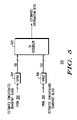
- FIG. 1 is a block diagram of a transmitter.
- FIG. 2 is a block diagram of a receiver.
- FIG. 3 is a block diagram of the turbo encoder of FIG. 1 .
- FIG. 4 is a block diagram of transport block former on the transmitter side.
- FIG. 5 is a block diagram of a transport block assembler on the receiver side.
- FIG. 6 is a flow chart showing operation of the transmitter of FIG. 1 .
- FIG. 7 is a flow chart showing operation of the receiver of FIG. 2 .
- a method and apparatus for turbo coding and decoding is provided herein.
- a concatenated transport block (CTB) of length X is received and a forward error correction (FEC) block size K I is determined from a group of available non-contiguous FEC block sizes between K min and K max , and wherein K min ⁇ K I ⁇ K max and wherein K I is additionally based on X.
- the concatenated transport block of length X is segmented into C segments each of size substantially equal to K I .
- An FEC codeword for each of the C segments is determined using FEC block size K I ; and the C FEC codewords are transmitted over the channel.
- a concatenated transport block (CTB) of length X is received and two FEC block sizes K I ⁇ 1 and K I are determined from a group of non-contiguous FEC block sizes, wherein the available non-contiguous FEC block sizes are between K min and K max , and wherein K min ⁇ K I ⁇ 1 ⁇ K max , K min ⁇ K I ⁇ K max , and wherein K I ⁇ 1 and K I are additionally based on X.
- the concatenated transport block of length X is segmented into C segments each of size substantially equal to K I ⁇ 1 or K I .
- An FEC codeword for each of the C segments is determined using FEC block sizes K I or K I ⁇ 1 , and the C FEC codewords are transmitted over the channel.
- the benefit of the above methods is that they reduce the padding of filler bits required to encode the CTB, while using the fewest number of segments allowed by the available non-contiguous FEC block sizes.
- the second method uses two different (but adjacent) FEC block sizes to minimize the number of filler bits while using the fewest number of segments as allowed by the available non-contiguous FEC block sizes.
- the FEC block sizes for the segment sizes and the number of segments for the two embodiments may be determined using simple logic circuitry.
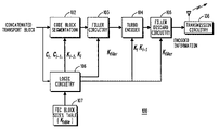
- FIG. 1 is a block diagram of transmitter 100 .
- transmitter 100 comprises code block segmentation circuitry 102 , filler circuitry 103 , turbo encoder 104 , filler discard circuitry 105 , transmitter 108 , logic circuitry 106 , and table/storage 107 .
- Transmitter 100 additionally comprises of receiving circuitry (not shown in FIG. 1 ) that receives a concatenated transport block of length X.
- Logic circuitry 106 determines an available FEC block size K I from a group of non-contiguous FEC block sizes 107 , wherein the available non-contiguous FEC block sizes are between K min and K max , and wherein K min ⁇ K I ⁇ K max , and wherein K I is additionally based on X.
- Code block segmentation circuitry 102 segments the concatenated transport block of length X into C segments of sizes substantially equal to K I ; and encoding circuitry 104 determines an FEC codeword for each of the C segments using FEC block size K I .
- transmission circuitry 108 transmits the C FEC codewords over a channel.
- the transmitter 100 comprises receiving circuitry (not shown in the FIG. 1 ) that receives a concatenated transport block of length X, logic circuitry 106 that determines two available FEC block sizes K I ⁇ 1 and K I from a group of non-contiguous FEC block sizes 107 , wherein the available non-contiguous FEC block sizes are between K min and K max , and wherein K min ⁇ K I ⁇ 1 ⁇ K max , K min ⁇ K I ⁇ K max , and wherein K I ⁇ 1 and K I are additionally based on X.
- Transmitter 100 comprises code block segmentation circuitry 102 that segments the concatenated transport block of length X into C segments of sizes substantially equal to K I ⁇ 1 or K I , and encoding circuitry 104 that determines an FEC codeword for each of the C segments using FEC block size K I or K I ⁇ 1 . Finally transmission circuitry 108 is provided that transmits the C FEC codewords over a channel.
- Encoding circuitry 104 is preceded by filler circuitry 103 that inserts filler bits into the segments to form an FEC input block.
- FEC encoder 104 encodes the FEC input block, and filler discard circuitry 105 discards bits related to the filler bits.
- circuitry 102 During operation of transmitter 100 , data in the form of a concatenated transport block is received by circuitry 102 . Circuitry 102 prepares the concatenated transport block before Forward Error Correction (FEC) encoding.
- FEC Forward Error Correction
- the range of the CTB sizes may be different from the range of the FEC block sizes supported by the underlying FEC scheme in the physical layer for a communication system. Therefore, it is necessary to define a rule that divides a CTB into segments that can be efficiently handled by the FEC.
- CTB sizes i.e., X
- the maximum FEC block size that FEC encoder 104 can handle. Therefore, the CTB needs to be segmented by circuitry 102 into a number of smaller-sized segments and each segment needs to be encoded by FEC encoder 104 into a separate FEC codeword.
- Circuitry 102 uses a code block segmentation rule that is designed to achieve good performance (i.e., the aggregate performance of the segments for a given CTB) with the underlying FEC. It involves the following aspects for any given CTB size:
- an EUTRA turbo coder may be defined for only a limited set of FEC block sizes (interleaver sizes).
- segment size When the segment size is equal to an available FEC block size, then the segment can be taken as an FEC input block directly (thus no need of filler bit insertion). However, when the segment size is not equal to any available FEC block sizes, filler bit padding may be applied, and the next larger available FEC block size (i.e., interleaver size) chosen from K table 107 may be used.
- the segmentation rules take the following properties of turbo coding into account.
- Property (b) suggests that it is not necessary to include interleavers for very large sizes in the table (K table ).
- the FEC block sizes defined in K table may depend on other factors. For example, i) for reduced storage/complexity, a small number of interleavers in K table may be desirable, and ii) the maximum interleaver size defined in K table may be chosen to limit the number of segments per CTB, thus limiting the segmentation penalty of a CTB.
- the segmentation penalty is the performance loss due to dividing a CTB into several segments instead of encoding the entire CTB into one FEC codeword.
- Property (c) suggests that the minimum number of segments should be used to reduce segmentation penalty.
- the sum of all segments is equal to the concatenated transport block size X, i.e., the segment sizes are constrained by the following equation.
- the next section describes the determination of the FEC block size used for FEC encoding, one for each of the C segment size.
- the rule for determining the FEC block size (interleaver size) for turbo coder as described in Release 6 of the 3GPP standard is as follows
- K max 5114 is the maximum interleaver size for Rel 6 Turbo code
- C is the number of segments (or code blocks)
- K I is the interleaver size
- Y is the total number of filler bits inserted for the CTB of size X when C FEC input blocks of size K I is used.
- a CTB of size X is segmented into C segments of approximately equal size, and each segment is encoded using a turbo code with a K I -bit interleaver. If Y>0, Y known bits are padded to the beginning of the first segment before encoding.
- the number of filler bits is bounded by C, the number of segments used for code block segmentation.
- the FEC block sizes may be defined only for non-contiguous sizes (a coarser set of interleaver sizes) K table .
- segment sizes that are not equal to any available FEC block sizes i.e., not defined in K table ) need to be handled using filler bits before FEC encoding (and puncturing after encoding to arrive at a desired code rate).
- One method is to modify (1) and let all segments be encoded with a single interleaver size K I , where
- the number of filler bits can be controlled by varying the FEC block size granularity in K table .
- the number of filler bits can also be reduced using another approach as described next.
- any K I ( ⁇ X/C ⁇ ) can be chosen from K table for FEC encoding at the cost of potentially increased number of filler bits.
- logic circuitry 106 determines the number of segments using the following relation
- C I ⁇ 1 and C I are the number of segments that are encoded using FEC block sizes K I ⁇ 1 and K I , respectively, where K I is the smallest size from available FEC block sizes that is greater than or equal to ⁇ X/C ⁇ , and D I denotes the difference between the adjacent interleaver sizes K I ⁇ 1 and K I .
- the code block segmentation forms C segments, of which C I ⁇ 1 segments are FEC-encoded with a FEC block size K I ⁇ 1 .
- K I ⁇ 1 size is allowed but not actually used.
- this method requires fewer filler bits than padding all C segments to the larger FEC block size K I .
- This method is optimal in that the number of filler bits Y′′ added per CTB is guaranteed to be least while using the fewest segments as possible. Y′′ is determined as follows
- segment sizes obtained after code block segmentation have the following constraints, assuming (without loss of generality that the first C I segments are encoded with K I and rest with K I ⁇ 1 ).
- a proper FEC block size needs to be chosen from table 107 of non-contiguous FEC block sizes.
- Logic circuitry 106 performs the task of choosing the appropriate FEC block size/sizes as discussed above.
- An example of table 107 is given in Table 1. For example, in first case, logic circuitry 106 chooses FEC block size from the available non-contiguous FEC block sizes between K min and K max , and wherein K min ⁇ K I ⁇ K max , and wherein K I is additionally based on X.
- the underlying FEC coder 104 supports only a limited set of FEC block sizes (or input sizes). Without loss of generality, it is assumed that FEC coder 104 is a turbo coder, and the set of FEC block sizes supported by the turbo coder is the set of interleaver sizes for which the turbo code internal interleaver is defined. However, one of ordinary skill in the art will recognize that other FEC schemes may be used in 104 , including low-density parity check (LDPC) codes, convolutional codes, block turbo codes, Reed-Solomon codes, etc.
- LDPC low-density parity check
- this information is passed to code block segmentation circuitry 102 where the CTB (X bits) is segmented into C segments which are encoded with FEC block size K I , if only one FEC block size is allowed. Alternatively, if two adjacent FEC block sizes are allowed, the code block segmentation circuitry 102 may output C I segments which are to be encoded with FEC block size K I and C I ⁇ 1 segments which are to be encoded FEC block size K I ⁇ 1 .
- the number of filler bits (padded for each segment) may be determined based on the segment size and the FEC block size being used for FEC encoding of the segment. There are at least two ways to distribute the overall filler bits into the C segments.
- Concentrated-filler Put the filler bits into as few segments as possible without making the segment sizes too small. In one example, all filler bits may appear in the beginning of the first segment. The advantage is that only one segment (containing all the filler bits) needs to be handled separately. Moreover, the filler bits can be padded to the segment that is encoded with the larger FEC block size K I rather than smaller FEC block size K I ⁇ 1 when two FEC block sizes are used for a CTB. This method is particularly attractive when allowing two adjacent FEC block sizes for encoding.
- Distributed-filler Distribute the filler bits evenly (as much as possible) into a plural of segments.
- the filler bits can be distributed to as many as all C segments.
- a preferred embodiment is to append Y′′ (if allowing two adjacent FEC block sizes; Y if allowing one FEC block size only) consecutive filler bits to the front of the one of the segments (e.g., the first or the last) using FEC block size K I before sending it to the encoder. In terms of performance, it is equivalent to appending the Y′′ consecutive filler bits to the end of a segment having FEC block size K I .
- an FEC codeword is determined using the steps of inserting filler bits into the segment to form an FEC input block; FEC encoding the FEC input block; and discarding bits related to the filler bits.
- FIG. 2 is a block diagram of a receiver.
- the received signal vector goes through the code block de-segmentation circuitry 202 which organizes portions of received signal vector according to the segment they are associated with.
- the segment size, number of segments, FEC block size used to turbo-decode each segment, number of filler bits may be determined using logic circuitry 213 and available FEC block size table 215 in a fashion similar to that at the encoder.
- the filler handling circuitry 204 uses the knowledge of the location of filler bits to benefit turbo decoder 206 , for e.g., by setting the LLRs corresponding to filler bits to a high magnitude.
- circuitry 208 discards the filler bits to obtain estimate of a segment.
- the code block assembler 211 assembles the estimated transport by suitably collecting and arranging the estimates of the segments obtained from circuitry 208 .
- This section provides a specific way of determining the FEC codeword.
- the method takes advantage of the knowledge of filler bits insertion at the transmitter is described. In particular, the method determines which bits (both systematic and parity bits) can be discarded from the turbo encoder output with no or negligible significant performance degradation.
- the filler bits are known, and hence the systematic bits of these bits (equal to the known bits) can be discarded prior to transmission. However, it is not clear if any parity bits can be discarded.
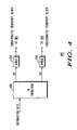
- FIG. 3 is a block diagram of turbo encoder 104 of FIG. 1 .
- input block of length K bits enters both interleaver 301 and constituent encoder 302 .
- Interleaver 301 interleaves the input block and passes the input block in interleaved order to constituent encoder 303 .
- Constituent encoder 303 then encodes the interleaved input block.
- constituent encoder 302 encodes the original input block.
- the codeword block x is composed of systematic block (equal to the FEC input block), output of constituent encoder 302 , and output of constituent encoder 303 .
- the codeword block x is then sent to circuitry 105 .
- K filler filler bits (usually 0's) are inserted at the beginning of the turbo code input block
- the systematic bits and the parity bits of the constituent encoder 302 corresponding to the K filler bit positions are all zeros. Therefore, these bits may be discarded at the transmitter and the receiver can utilize this knowledge while performing turbo decoding.
- the K filler bits are scrambled due to the turbo code interleaver and hence the parity bits of constituent encoder 303 corresponding to the filler bits are not known and thus cannot be discarded simply.
- the initial state of the constituent encoders may not be always zero.
- the initial state and the final state for a constituent encoder are equal and they depend on the input block. Therefore, when K filler consecutive filler bits (i.e., zeros) are inserted at the beginning of the turbo code input block, the parity bits of constituent encoder 302 corresponding to the K filler bit positions are not always zeros. However, it can be proven that most of these K filler parity bits of the constituent encoder 302 carry no information.
- the FEC encoder can be a tail-biting convolutional code used alone, or a tail-biting convolutional code used as a constituent code of a turbo coder.
- groups of systematic bits corresponding to the filler bits may be discarded; and the parity bits corresponding to the groups of filler bits at the output of a constituent encoder may be discarded, wherein the constituent encoder takes the FEC input block without interleaving for tail-biting turbo coders.
- S(i) may not be a constant.
- the states S(j) in between may not be a constant or equal to state S(i), i ⁇ j ⁇ i+(2 m ⁇ 1)g.
- the transmitter can take advantage of (7) by discarding the constituent encoder output during those steps, as these filler bits do not change the shift register state and thus providing no information for the decoder.
- the decoder within the receiver can also take advantage of (7) similarly based on the knowledge of filler bit positions and values.
- constituent encoder 303 the K filler filler bits may get dispersed due to the turbo code interleaver. Therefore, it may not be possible to discard the parity bits from the constituent encoder 303 without affecting performance.
- code block segmentation rule may be used, e.g., hybrid-Automatic Repeat reQuest (HARQ), Multiple Input Multi Output (MIMO), etc.
- HARQ hybrid-Automatic Repeat reQuest
- MIMO Multiple Input Multi Output
- Transport Block (TB) Former TB
- the code block segmentation rule described above is applied to a concatenated transport block (CTB) on a hybrid ARQ (HARQ) channel.
- CTB concatenated transport block
- HARQ hybrid ARQ
- the information bits than needs to be sent to a single user from the base station within a transmission time interval (TTI) may need to be divided into at least one transport block, thus going through at least one HARQ channel.
- TTI transmission time interval
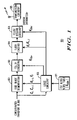
- FIG. 4 shows an example wherein the information bits are transmitted using two HARQ channels (corresponding to HARQ 1 , and HARQ 2 ), and two transport blocks TB 1 and TB 2 .
- information bits of length A are received by TB formation circuitry 402 to be transmitted on one or more spatial streams.
- Circuitry 402 designates X′ bits as a transport block TB 1 , where X′ ⁇ A; HARQ 1 processor 404 attaches CRC bits to the X′ bits to form the concatenated transport block of length X; the concatenated transport block of length X is mapped to a first HARQ channel.
- the concatenated transport block is sent to the code block segmentation circuitry 102 .
- HARQ 2 processor 406 attaches CRC bits to Y bits form a second concatenated transport block; the concatenated transport block is mapped to a second HARQ channel.
- the concatenated transport block is sent to the code block segmentation circuitry 102 .
- circuitry 404 and 406 may perform additional functions such as other functionalities related to HARQ, adding control information, etc.
- FIG. 4 Though the concepts in FIG. 4 are illustrated using two HARQ channels, they can be easily extended to a plurality of HARQ channels. If more than one HARQ channel is supported to a user within a Transmission Time Interval (TTI), the code block segmentation rule may be applied to each TB.
- TTI Transmission Time Interval
- Multiple HARQ channels may occur due to having too many FEC codewords (or segments) per TTI per user, such as from large bandwidth (e.g., 20 MHz), higher order modulation (e.g., 64 QAM), multistream MIMO, etc.
- Multiple HARQ channels may also be used for TBs that have different QoS, such as VoIP and best-effort data.
- a MIMO codeword comprises the bits that are sent to a single user within a TTI on one MIMO stream.
- a MIMO codeword may comprise one or more FEC codewords.
- x e.g. 8
- FEC codewords value of x determined by the eNodeB scheduler in EUTRA.
- two TBs are created as follows. The packet is divided approximately evenly between two TBs, each TB having nearly the same number of FEC codewords of approximately the same size.
- TBi refers to TB of i-th HARQ channel; numbers 1 through 4 indicates the MIMO codeword (or stream) number.
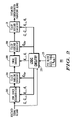
- FIG. 5 is a block diagram of receiver processing when information bits are received over at least one HARQ channel.
- the received bits from the code block assembler 211 are input to the appropriate channel processors 504 and 506 .
- the output of the channel processors are the estimated transports blocks TB 1 and TB 2 which are input to the TB assembler circuitry 502 which combines the TBs and outputs estimated information bits.
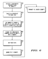
- FIG. 6 is a flow chart showing operation of the transmitter of FIG. 1 .
- the logic flow begins at step 601 where segmentation circuitry receives a concatenated transport block of length X.
- logic circuitry accesses table 107 and chooses an appropriate FEC block size.
- the FEC block size K I is determined from a group of non-contiguous FEC block sizes located in table 107 , where the available non-contiguous FEC block sizes in table 107 are between K min and K max , and wherein K min ⁇ K I ⁇ K max .
- K I is based on X.
- X is determined by logic circuitry 106 from the concatenated transport block.
- step 605 the number of segments C and the FEC lock sizes are passed to segmentation circuitry 102 and at step 607 segmentation circuitry segments the concatenated transport block of length X into C segments of size substantially equal to K I (or alternatively K I and K I ⁇ 1 ).
- Filler bits are added (if necessary) at step 609 via circuitry 103 and at step 611 each of the C segments are encoded (i.e., an FEC codeword is determined for each of the C segments).
- step 613 the FEC codewords are transmitted via transmission circuitry 108 .
- the step of determining an FEC codeword comprises the steps of inserting filler bits into the segment to form an FEC input block, FEC encoding the FEC input block, and discarding bits related to the filler bits.
- This step may entail inserting groups of consecutive filler bits into a segment to form an FEC input block where the group length is a multiple of 7, FEC encoding the FEC input block, and discarding bits related to the filler bits.
- Discarding filler bits comprises the steps of discarding groups of systematic bits corresponding to the filler bits and discarding the parity bits corresponding to the groups of filler bits at the output of constituent encoder 1 , where constituent encoder takes the FEC input block without interleaving for tail-biting turbo coders.
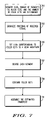
- FIG. 7 is a flow chart showing operation of the receiver of FIG. 2 .
- the logic flow begins at step 701 where the segment size, number of segments, FEC block size used to turbo-decode each segment, and the number of filler bits are determined using logic circuitry 213 and table 215 .
- the FEC block size K I is determined from a group of non-contiguous FEC block sizes located in table 215 , where the available non-contiguous FEC block sizes in table 215 are between K min and K max , and wherein K min ⁇ K I ⁇ K max .
- K I is based on X.
- X is determined by logic circuitry 213 from the received signal vector.
- a received signal vector goes through code block de-segmentation circuitry 202 which organizes portions of received signal vector according to the C segment they are associated with.
- filler handling circuitry 204 uses the knowledge of the location of filler bits to benefit turbo decoder 206 , for e.g., by setting the LLRs corresponding to filler bits to a high magnitude.
- Each of the C segments is decoded at step 707 .
- circuitry 208 discards the filler bits to obtain estimate of a segment (step 709 ).
- Code block assembler 211 assembles the estimated transport by suitably collecting and arranging the estimates of the segments obtained from circuitry 208 (step 711 ).
Abstract
Description
- The present invention relates generally to encoding and decoding data and in particular, to a method and apparatus for turbo coding and decoding data.
- Digital data transmissions over wired and wireless links sometimes may be corrupted, for instance, by noise in the link or channel, by interference from other transmissions, or by other environmental factors. To combat the errors introduced by the channel, many communication systems employ error-correction techniques to aid in communication.
- One technique utilized for error correction is turbo coding of an information block to be transmitted. Utilizing such a technique, an encoder within the transmitter of a communication system will encode an input block u of length K bits into a codeword block x of N bits. The codeword block x is then transmitted over the channel, possibly after further processing such as channel interleaving as defined in the IEEE 802.16e specifications. At the receiver, the turbo decoder takes the received signal vector y of length N as input, and generates an estimate û of vector u.
- Typically the turbo encoder is composed of two constituent convolutional encoders. The first constituent encoder takes the input block u as input in its original order, and the second constituent encoder takes the input block u in its interleaved order after passing u through a turbo interleaver π. The turbo encoder output x is composed of the systematic bits (equal to the input block u), the parity bits from the first constituent encoder, and the parity bits from the second constituent encoder.
- Correspondingly the turbo decoder within the receiver of the communication system is composed of two constituent convolutional decoders, one for each constituent code. The constituent decoders are separated by the interleaver π and the corresponding deinterleaver π−1. Messages in the format of log-likelihood ratios (LLRs) are passed between the constituent decoders iteratively. The decision û is made after several iterations.
- The turbo interleaver π is the key component in the turbo code design. It is responsible for scrambling the input block u in a pseudo-random fashion, thus providing the codewords x with good weight distribution, hence good error-correcting capabilities. In addition to decoding performance, the turbo interleaver π has significant impact on the implementation of the turbo decoder within the receiver. Usually, turbo codes performance improves with increasing interleaver length. However, there is a diminishing return in increasing the interleaver size. In practice, the maximum Forward Error Correction (FEC) block size (i.e., interleaver size) of a turbo code is limited to a certain value due to complexity and delay reasons. Hence, if the size of the input block (concatenated transport block or CTB) is larger than the maximum FEC block size supported by the turbo code, the CTB is segmented (e.g., using code block segmentation rule) into several small segments, each of which is processed separately by the turbo encoder at the transmitter and correspondingly by the turbo decoder at the receiver.
- In some systems, the turbo code may be designed to support only a small number of FEC block sizes for various reasons (e.g., high speed decoding, reduced storage, etc). Therefore, a need exists for a method and apparatus for turbo coding and decoding that appropriately matches the CTB to available FEC block sizes.
-
FIG. 1 is a block diagram of a transmitter. -
FIG. 2 is a block diagram of a receiver. -
FIG. 3 is a block diagram of the turbo encoder ofFIG. 1 . -
FIG. 4 is a block diagram of transport block former on the transmitter side. -
FIG. 5 is a block diagram of a transport block assembler on the receiver side. -
FIG. 6 is a flow chart showing operation of the transmitter ofFIG. 1 . -
FIG. 7 is a flow chart showing operation of the receiver ofFIG. 2 . - In order to address the above-mentioned need, a method and apparatus for turbo coding and decoding is provided herein. During operation, a concatenated transport block (CTB) of length X is received and a forward error correction (FEC) block size KI is determined from a group of available non-contiguous FEC block sizes between Kmin and Kmax, and wherein Kmin≦KI<Kmax and wherein KI is additionally based on X. The concatenated transport block of length X is segmented into C segments each of size substantially equal to KI. An FEC codeword for each of the C segments is determined using FEC block size KI; and the C FEC codewords are transmitted over the channel.
- In an alternate embodiment, a concatenated transport block (CTB) of length X is received and two FEC block sizes KI−1 and KI are determined from a group of non-contiguous FEC block sizes, wherein the available non-contiguous FEC block sizes are between Kmin and Kmax, and wherein Kmin≦KI−1<Kmax, Kmin≦KI≦Kmax, and wherein KI−1 and KI are additionally based on X. The concatenated transport block of length X is segmented into C segments each of size substantially equal to KI−1 or KI. An FEC codeword for each of the C segments is determined using FEC block sizes KI or KI−1, and the C FEC codewords are transmitted over the channel.
- The benefit of the above methods is that they reduce the padding of filler bits required to encode the CTB, while using the fewest number of segments allowed by the available non-contiguous FEC block sizes. In particular, the second method uses two different (but adjacent) FEC block sizes to minimize the number of filler bits while using the fewest number of segments as allowed by the available non-contiguous FEC block sizes. Moreover, the FEC block sizes for the segment sizes and the number of segments for the two embodiments may be determined using simple logic circuitry.
- Prior to describing encoding and decoding data, the following definitions are provided to set the necessary background:
-
- For ease of notation, a concatenated transport block refers to the result of concatenating one or more transport blocks, after adding overhead such as CRC bits to each transport block.
- X denotes the concatenated transport block size (e.g., length of the concatenated transport block in bits).
- Y denotes the total number of filler bits added to a concatenated transport block.
- C denotes the number of segments a concatenated transport block gets segmented into.
- CBSSi denotes the size of the ith segment of a concatenated transport block (i=1, . . . C, where C is the segment size. CBSS stands for code block segment size.
- KI−1 and KI denote FEC block sizes (e.g., sizes for which turbo code internal interleaver are defined) that may be used to FEC encode the segments of a concatenated transport block.
- Ktable denotes a set of available non-contiguous FEC block sizes (sizes for which a turbo code internal interleaver is defined).
- Kfiller denotes the number of filler bits added to a segment.
- R denotes the mother code rate of the turbo coder (e.g., R=⅓ for the 3GPP Turbo Code).
- R−1 is the inverse of mother code rate of turbo coder (e.g., R−1=3 for the 3GPP Turbo Code).
- Ntb is the number of tail bits in the FEC codeword at the output of FEC encoder. In particular,
- Ntb=12 for 3GPP turbo code with tail bits.
- Ntb=0 for a 3GPP turbo code with tail-biting.
- π denotes the turbo code internal interleaver.
- The flooring operation └x┘ denotes the largest integer smaller than or equal to x and the ceiling operation ┌x┐ denotes the smallest integer larger than or equal to x.
- Turning now to the drawings, wherein like numerals designate like components,
FIG. 1 is a block diagram oftransmitter 100. As shown,transmitter 100 comprises codeblock segmentation circuitry 102,filler circuitry 103,turbo encoder 104, fillerdiscard circuitry 105,transmitter 108,logic circuitry 106, and table/storage 107.Transmitter 100 additionally comprises of receiving circuitry (not shown inFIG. 1 ) that receives a concatenated transport block of length X.Logic circuitry 106 determines an available FEC block size KI from a group of non-contiguousFEC block sizes 107, wherein the available non-contiguous FEC block sizes are between Kmin and Kmax, and wherein Kmin≦KI<Kmax, and wherein KI is additionally based on X. Codeblock segmentation circuitry 102 segments the concatenated transport block of length X into C segments of sizes substantially equal to KI; and encodingcircuitry 104 determines an FEC codeword for each of the C segments using FEC block size KI. Finallytransmission circuitry 108 transmits the C FEC codewords over a channel. - In another embodiment, the
transmitter 100 comprises receiving circuitry (not shown in theFIG. 1 ) that receives a concatenated transport block of length X,logic circuitry 106 that determines two available FEC block sizes KI−1 and KI from a group of non-contiguousFEC block sizes 107, wherein the available non-contiguous FEC block sizes are between Kmin and Kmax, and wherein Kmin≦KI−1<Kmax, Kmin≦KI≦Kmax, and wherein KI−1 and KI are additionally based on X.Transmitter 100 comprises codeblock segmentation circuitry 102 that segments the concatenated transport block of length X into C segments of sizes substantially equal to KI−1 or KI, andencoding circuitry 104 that determines an FEC codeword for each of the C segments using FEC block size KI or KI−1. Finallytransmission circuitry 108 is provided that transmits the C FEC codewords over a channel. -
Encoding circuitry 104 is preceded byfiller circuitry 103 that inserts filler bits into the segments to form an FEC input block.FEC encoder 104 encodes the FEC input block, and filler discardcircuitry 105 discards bits related to the filler bits. - During operation of
transmitter 100, data in the form of a concatenated transport block is received bycircuitry 102.Circuitry 102 prepares the concatenated transport block before Forward Error Correction (FEC) encoding. - In general, the range of the CTB sizes (i.e., X) may be different from the range of the FEC block sizes supported by the underlying FEC scheme in the physical layer for a communication system. Therefore, it is necessary to define a rule that divides a CTB into segments that can be efficiently handled by the FEC. In particular, CTB sizes (i.e., X) are often much larger than the maximum FEC block size that
FEC encoder 104 can handle. Therefore, the CTB needs to be segmented bycircuitry 102 into a number of smaller-sized segments and each segment needs to be encoded byFEC encoder 104 into a separate FEC codeword. -
Circuitry 102 uses a code block segmentation rule that is designed to achieve good performance (i.e., the aggregate performance of the segments for a given CTB) with the underlying FEC. It involves the following aspects for any given CTB size: -
- Choosing the number of segments C;
- Choosing the sizes of each segment;
- Inserting the filler bits before FEC encoding and the removing of filler bits after FEC encoding, if the segment size cannot be handled directly by the FEC.
- The proposed segmentation rules are particularly useful for Evolved-UMTS Terrestrial Radio Access (EUTRA) system where a turbo coder may be defined for only a limited set of FEC block sizes (interleaver sizes). Unlike the Release 6 3GPP Turbo coder that defines 5075 interleavers of contiguous sizes, one for each interleaver size KI between 40 bits and 5114 bits, an EUTRA turbo coder may define a limited number of FEC block sizes Ktable (e.g., 40-50 interleavers with non-contiguous sizes ranging from 128 bits to 6144 bits) to cover a large number of segment sizes (e.g., 6144-128+1=6017 sizes). When the segment size is equal to an available FEC block size, then the segment can be taken as an FEC input block directly (thus no need of filler bit insertion). However, when the segment size is not equal to any available FEC block sizes, filler bit padding may be applied, and the next larger available FEC block size (i.e., interleaver size) chosen from
K table 107 may be used. - The segmentation rules take the following properties of turbo coding into account.
-
- (a) Turbo code performance improves as the FEC block size increases.
- (b) Turbo code performance improvement via increasing FEC block sizes has diminishing returns beyond a few thousand bits.
- (c) A CTB is received correctly only if all the segments are received correctly.
- Properties (a) and (c) indicate that the overall performance is likely to be dominated by the segment having the worst performance. Thus, it is preferable to have segments that are approximately of equal sizes so that they are FEC encoded with approximately equal FEC block sizes (and hence accorded approximately equal error protection from FEC perspective).
- Property (b) suggests that it is not necessary to include interleavers for very large sizes in the table (Ktable). However, the FEC block sizes defined in Ktable may depend on other factors. For example, i) for reduced storage/complexity, a small number of interleavers in Ktable may be desirable, and ii) the maximum interleaver size defined in Ktable may be chosen to limit the number of segments per CTB, thus limiting the segmentation penalty of a CTB. The segmentation penalty is the performance loss due to dividing a CTB into several segments instead of encoding the entire CTB into one FEC codeword.
- Property (c) suggests that the minimum number of segments should be used to reduce segmentation penalty.
- Considering all the above, the number of segments is C=┌X/Kmax┐, where Kmax is the maximum FEC block size defined in Ktable. Assuming that CBSSi denote the segment size of the ith segment (i=1, . . . of the concatenated transport block, the sum of all segments is equal to the concatenated transport block size X, i.e., the segment sizes are constrained by the following equation.
-
- The next section describes the determination of the FEC block size used for FEC encoding, one for each of the C segment size.
- Given that a CTB of length X is the input to the code block segmentation function, the rule for determining the FEC block size (interleaver size) for turbo coder as described in Release 6 of the 3GPP standard is as follows
-
C=┌X/K max┐, -
K I=max(40,┌X/C┐), (1) -
Y=CK I −X. - where Kmax=5114 is the maximum interleaver size for Rel 6 Turbo code, C is the number of segments (or code blocks), KI is the interleaver size, and Y is the total number of filler bits inserted for the CTB of size X when C FEC input blocks of size KI is used. In essence, a CTB of size X is segmented into C segments of approximately equal size, and each segment is encoded using a turbo code with a KI-bit interleaver. If Y>0, Y known bits are padded to the beginning of the first segment before encoding. Since the FEC block sizes (i.e., interleavers) are defined for all sizes between Kmin=40 and Kmax=5114 in Release 6 3GPP turbo code, the number of filler bits is bounded by C, the number of segments used for code block segmentation.
- However, in other systems such as the one being considered for EUTRA, the FEC block sizes (interleaver sizes) may be defined only for non-contiguous sizes (a coarser set of interleaver sizes) Ktable. In such cases, segment sizes that are not equal to any available FEC block sizes (i.e., not defined in Ktable) need to be handled using filler bits before FEC encoding (and puncturing after encoding to arrive at a desired code rate).
- Assuming that a turbo coder supports only a limited number of FEC block sizes distributed between Kmin and Kmax, both inclusive, two simple methods of code block segmentation of a concatenated transport block of length X using Ktable are described next. These methods use as few segments as possible while they also reduce the number of filler bits that are required for encoding,
- One method is to modify (1) and let all segments be encoded with a single interleaver size KI, where
-
- where i, 1≦i≦T, indexes into the group of non-contiguous FEC block sizes available in Ktable, assuming the T sizes in Ktable are sorted in ascending order. In essence, this method chooses the smallest KI from Ktable that is greater than or equal to ┌X/C┐, i.e., KI=┌X/C┐+δ, where 0≦δ<KI-K1−1, and KI−1<┌X/C┐. Note that it is assigned that KI−1=0 when I=1. Therefore, the number of filler bits is given by
-
- Therefore, Y is large when δ is large. The following examples illustrate how the number of available FEC block sizes (Ktable) affects Y.
-
- If Ktable has all the values between Zmin=40 and Zmax=5114, the maximum number of filler bits is equal to
C− 1. - If Ktable has T=100 values uniformly distributed between Zmin=40 and Zmax=5114, the maximum total number of filler bits padded to all segments is approximately equal to 50×C.
- If Ktable has all the values between Zmin=40 and Zmax=5114, the maximum number of filler bits is equal to
- Therefore, the number of filler bits can be controlled by varying the FEC block size granularity in Ktable. The number of filler bits can also be reduced using another approach as described next. However, before discussing the next method, it is noted that in a general case, any KI(≧┌X/C┐) can be chosen from Ktable for FEC encoding at the cost of potentially increased number of filler bits. In this case, the segment sizes obtained after code block segmentation satisfy CBSSi≦KI, for i=1, . . . C. In this case,
logic circuitry 106 determines the number of segments using the following relation -
C=┌X/K max┐, - Instead of using one FEC block size KI for encoding all the segments of a given CTB, it is proposed that two adjacent FEC block sizes KI−1 and KI, KI−1<KI, 1≦I≦T, be selected from Ktable. Note that it is assigned that KI−1=0 when I=1. The number of segments C and the larger FEC block size KI are still chosen to be the same as in earlier cases, i.e., C is still computed as in (1) and KI is still computed as in (2). However, the number of segments encoded with size KI−1 and size KI are determined as follows (for easy understanding, all involved computations are repeated below). In this case,
logic circuitry 106 performs the following operations to find the number of segments, -
C=┌X/K max =C I +C I−1, -
Y=CK I −X, -
D I =K I −K I−1, -
C I−1 =└Y/D I┘, -
C I =C−└Y/D I┘, (4) - and CI−1 and CI are the number of segments that are encoded using FEC block sizes KI−1 and KI, respectively, where KI is the smallest size from available FEC block sizes that is greater than or equal to ┌X/C┐, and DI denotes the difference between the adjacent interleaver sizes KI−1 and KI.
- Note that in (4) Y does not indicate the number of filler bits required if allowing two adjacent sizes; but indicates the number of filler bits required had only one size of KI is used for all C segments.
- Thus, the code block segmentation forms C segments, of which CI−1 segments are FEC-encoded with a FEC block size KI−1. Note that when Y<DI, (4) gives CI−1=0, and this method degenerates to using one FEC block size of KI. (i.e., KI−1 size is allowed but not actually used.) On the other hand, when Y≧DI, this method requires fewer filler bits than padding all C segments to the larger FEC block size KI. This method is optimal in that the number of filler bits Y″ added per CTB is guaranteed to be least while using the fewest segments as possible. Y″ is determined as follows
-
Y″=C I−1 K I−1 +C I K I −X, (5) - It can be proven that Y″ is bounded by DI, regardless of C,
-
0≦Y″<K I −K I−1, (6) - In this case, the segment sizes obtained after code block segmentation have the following constraints, assuming (without loss of generality that the first CI segments are encoded with KI and rest with KI−1).
-
CBSS i ≦K I, for i=1, . . . C I -
CBSS i ≦K I−1, for i=C I+1, . . . C; if C I−1≧1. - Returning to
FIG. 1 , as discussed above, a proper FEC block size needs to be chosen from table 107 of non-contiguous FEC block sizes.Logic circuitry 106 performs the task of choosing the appropriate FEC block size/sizes as discussed above. An example of table 107 is given in Table 1. For example, in first case,logic circuitry 106 chooses FEC block size from the available non-contiguous FEC block sizes between Kmin and Kmax, and wherein Kmin≦KI≦Kmax, and wherein KI is additionally based on X. Particularly, if a single FEC block size KI is to be used,logic circuitry 106 chooses the smallest K, (from Ktable) that is not smaller than ┌X/C┐, i.e., KI=┌X/C┐+δ, where δ≧0, and KI−1<┌X/C┐. If, however, two FEC block sizes are to be used, KI−1 and KI are determined with equation (4) giving the number of segments that are encoded using FEC block sizes KI−1 and KI. -
TABLE 1 The set of FEC block sizes for which turbo coder internal interleaver is defined. Ktable 128 256 512 1024 2048 4096 144 288 576 1152 2304 4608 160 320 640 1280 2560 5120 176 352 704 1408 2816 5632 192 384 768 1536 3072 6144 208 416 832 1664 3328 216 440 888 1776 3568 240 480 960 1920 3840 - The
underlying FEC coder 104 supports only a limited set of FEC block sizes (or input sizes). Without loss of generality, it is assumed thatFEC coder 104 is a turbo coder, and the set of FEC block sizes supported by the turbo coder is the set of interleaver sizes for which the turbo code internal interleaver is defined. However, one of ordinary skill in the art will recognize that other FEC schemes may be used in 104, including low-density parity check (LDPC) codes, convolutional codes, block turbo codes, Reed-Solomon codes, etc. - Once the number of segments C and the FEC block size for each segment is determined, this information is passed to code
block segmentation circuitry 102 where the CTB (X bits) is segmented into C segments which are encoded with FEC block size KI, if only one FEC block size is allowed. Alternatively, if two adjacent FEC block sizes are allowed, the codeblock segmentation circuitry 102 may output CI segments which are to be encoded with FEC block size KI and CI−1 segments which are to be encoded FEC block size KI−1. - The number of filler bits (padded for each segment) may be determined based on the segment size and the FEC block size being used for FEC encoding of the segment. There are at least two ways to distribute the overall filler bits into the C segments.
- Concentrated-filler. Put the filler bits into as few segments as possible without making the segment sizes too small. In one example, all filler bits may appear in the beginning of the first segment. The advantage is that only one segment (containing all the filler bits) needs to be handled separately. Moreover, the filler bits can be padded to the segment that is encoded with the larger FEC block size KI rather than smaller FEC block size KI−1 when two FEC block sizes are used for a CTB. This method is particularly attractive when allowing two adjacent FEC block sizes for encoding.
- Distributed-filler. Distribute the filler bits evenly (as much as possible) into a plural of segments. The filler bits can be distributed to as many as all C segments.
- For efficient implementation of the transmitter and the receiver, concentrated-filler is preferred. A preferred embodiment is to append Y″ (if allowing two adjacent FEC block sizes; Y if allowing one FEC block size only) consecutive filler bits to the front of the one of the segments (e.g., the first or the last) using FEC block size KI before sending it to the encoder. In terms of performance, it is equivalent to appending the Y″ consecutive filler bits to the end of a segment having FEC block size KI.
- Returning to
FIG. 1 , for each segment (produced by circuitry 102), an FEC codeword is determined using the steps of inserting filler bits into the segment to form an FEC input block; FEC encoding the FEC input block; and discarding bits related to the filler bits. - Each segment produced by
circuitry 102 is passed tofiller circuitry 103 where filler bit insertion takes place. If no filler bits are required, then filler circuitry is transparent, i.e., no filler bits are added (Kfiller=0). The segments (along with filler bits) are then passed toturbo encoder 104 where turbo encoding of the C segments leads to C FEC codewords. The filler bits are then discarded bycircuitry 105 and the resulting C codewords are appropriately transmitted bytransmission circuitry 108. If no filler bits are added bycircuitry 103, then filler discardcircuitry 105 is transparent, i.e., no filler bits are removed (Kfiller=0). Note that it is possible thatcircuitry 105 may not discard any bits corresponding to the filler bits. -
FIG. 2 is a block diagram of a receiver. During operation the received signal vector goes through the codeblock de-segmentation circuitry 202 which organizes portions of received signal vector according to the segment they are associated with. The segment size, number of segments, FEC block size used to turbo-decode each segment, number of filler bits may be determined usinglogic circuitry 213 and available FEC block size table 215 in a fashion similar to that at the encoder. Thefiller handling circuitry 204 uses the knowledge of the location of filler bits to benefitturbo decoder 206, for e.g., by setting the LLRs corresponding to filler bits to a high magnitude. After turbo decoding,circuitry 208 discards the filler bits to obtain estimate of a segment. Thecode block assembler 211 assembles the estimated transport by suitably collecting and arranging the estimates of the segments obtained fromcircuitry 208. - This section provides a specific way of determining the FEC codeword. The method takes advantage of the knowledge of filler bits insertion at the transmitter is described. In particular, the method determines which bits (both systematic and parity bits) can be discarded from the turbo encoder output with no or negligible significant performance degradation. In general, the filler bits are known, and hence the systematic bits of these bits (equal to the known bits) can be discarded prior to transmission. However, it is not clear if any parity bits can be discarded.
-
FIG. 3 is a block diagram ofturbo encoder 104 ofFIG. 1 . During operation, input block of length K, bits enters bothinterleaver 301 andconstituent encoder 302.Interleaver 301 interleaves the input block and passes the input block in interleaved order toconstituent encoder 303.Constituent encoder 303 then encodes the interleaved input block. In a similar manner,constituent encoder 302 encodes the original input block. The codeword block x is composed of systematic block (equal to the FEC input block), output ofconstituent encoder 302, and output ofconstituent encoder 303. The codeword block x is then sent tocircuitry 105. - In a conventional turbo encoder such as e.g., tailed turbo codes, the initial state of the constituent encoders (shift register contents) is assumed to be all-zero.
- In such case, when Kfiller filler bits (usually 0's) are inserted at the beginning of the turbo code input block, the systematic bits and the parity bits of the
constituent encoder 302 corresponding to the Kfiller bit positions are all zeros. Therefore, these bits may be discarded at the transmitter and the receiver can utilize this knowledge while performing turbo decoding. However, in theconstituent encoder 303, the Kfiller bits are scrambled due to the turbo code interleaver and hence the parity bits ofconstituent encoder 303 corresponding to the filler bits are not known and thus cannot be discarded simply. - When the turbo coder has tail-biting constituent encoders, the initial state of the constituent encoders may not be always zero. For tail-biting codes, the initial state and the final state for a constituent encoder are equal and they depend on the input block. Therefore, when Kfiller consecutive filler bits (i.e., zeros) are inserted at the beginning of the turbo code input block, the parity bits of
constituent encoder 302 corresponding to the Kfiller bit positions are not always zeros. However, it can be proven that most of these Kfiller parity bits of theconstituent encoder 302 carry no information. - In general, groups of consecutive filler bits are inserted into a segment to form an FEC input block wherein the group length is a multiple of 2′″−1 (=7 for the constituent convolutional codes within the 3GPP turbo coder). Then, the FEC input block is FEC encoded and parity bits related to the filler bits are discarded. The FEC encoder can be a tail-biting convolutional code used alone, or a tail-biting convolutional code used as a constituent code of a turbo coder.
- In particular, when used for turbo codes with tail-biting constituent codes, groups of systematic bits corresponding to the filler bits may be discarded; and the parity bits corresponding to the groups of filler bits at the output of a constituent encoder may be discarded, wherein the constituent encoder takes the FEC input block without interleaving for tail-biting turbo coders. This can be shown as follows.
- Let the state of the shift register of
constituent encoder 302 at step i be S(i), let m be the number of elements in the shift register, and let g be any integer greater than 0. When (2m−1)×g zeros are input to the constituent encoder from step i+1 to step i+(2m−1)×g, the following is a property of recursive convolutional encoder (such as the one used in Rel. 6 3GPP turbo code), -
S(i)=S(i+(2m−1)g) (7) - Note that S(i) may not be a constant. In addition, the states S(j) in between may not be a constant or equal to state S(i), i<j<i+(2m−1)g.
- Therefore, the state of the constituent encoder remains unchanged between step i+1 to step i+(2m−1)×g. Therefore, the transmitter can take advantage of (7) by discarding the constituent encoder output during those steps, as these filler bits do not change the shift register state and thus providing no information for the decoder. The decoder within the receiver can also take advantage of (7) similarly based on the knowledge of filler bit positions and values. Next, the above method is described with an example where Kfiller filler bits (zeros) are inserted in consecutive positions in the input of a tail-biting turbo code.
- Since Kfiller consecutive filler bits (zeros) are inserted in the turbo code input block, g=└Kfiller/(2m−1)┘, and therefore p×g×(2m−1) parity bits of
constituent encoder 302 may be discarded, where p is the number parity bits at the output of theconstituent encoder 302 that are generated for each bit in the FEC input block. Therefore, only the parity bits corresponding to the groups of filler bits at the output ofconstituent encoder 302 are discarded, whereinconstituent encoder 302 takes the FEC input block without interleaving for tail-biting turbo coders. - For a tail-biting 3GPP turbo coder, p=1 in
constituent encoder 1, m=3. Thus 7└Kfiller/(2m−1)┘ parity bits can be discarded fromconstituent encoder 302 for Kfiller consecutive filler bits. Since m=3, at most only 6 parity bits corresponding to the Kfiller filler bits ofconstituent encoder 302 may need to be kept at the output ofconstituent encoder 302. - In
constituent encoder 303, the Kfiller filler bits may get dispersed due to the turbo code interleaver. Therefore, it may not be possible to discard the parity bits from theconstituent encoder 303 without affecting performance. - The following section describes some example scenarios in which the code block segmentation rule may be used, e.g., hybrid-Automatic Repeat reQuest (HARQ), Multiple Input Multi Output (MIMO), etc.
- The code block segmentation rule described above is applied to a concatenated transport block (CTB) on a hybrid ARQ (HARQ) channel. Before code block segmentation, the information bits than needs to be sent to a single user from the base station within a transmission time interval (TTI) may need to be divided into at least one transport block, thus going through at least one HARQ channel. For example
FIG. 4 shows an example wherein the information bits are transmitted using two HARQ channels (corresponding to HARQ1, and HARQ2), and two transport blocks TB1 and TB2. During operation, information bits of length A are received byTB formation circuitry 402 to be transmitted on one or more spatial streams.Circuitry 402 designates X′ bits as a transport block TB1, where X′≦A;HARQ1 processor 404 attaches CRC bits to the X′ bits to form the concatenated transport block of length X; the concatenated transport block of length X is mapped to a first HARQ channel. The concatenated transport block is sent to the codeblock segmentation circuitry 102. -
Circuitry 402 designates W′=A−X′ bits from the information bits as a second transport block TB2;HARQ2 processor 406 attaches CRC bits to Y bits form a second concatenated transport block; the concatenated transport block is mapped to a second HARQ channel. The concatenated transport block is sent to the codeblock segmentation circuitry 102. - Note that
circuitry - Though the concepts in
FIG. 4 are illustrated using two HARQ channels, they can be easily extended to a plurality of HARQ channels. If more than one HARQ channel is supported to a user within a Transmission Time Interval (TTI), the code block segmentation rule may be applied to each TB. - Multiple HARQ channels may occur due to having too many FEC codewords (or segments) per TTI per user, such as from large bandwidth (e.g., 20 MHz), higher order modulation (e.g., 64 QAM), multistream MIMO, etc. Multiple HARQ channels may also be used for TBs that have different QoS, such as VoIP and best-effort data.
- A MIMO codeword comprises the bits that are sent to a single user within a TTI on one MIMO stream. Thus a MIMO codeword may comprise one or more FEC codewords. Sometimes a MIMO codeword is used to refer to the bits on a MIMO stream.
- Rules may be defined for the creation of a TB. In one embodiment, a TB shall comprise no more than x (e.g., x=8) FEC codewords (value of x determined by the eNodeB scheduler in EUTRA). In another embodiment, if more than x FEC codewords are needed for a TB, then two TBs are created as follows. The packet is divided approximately evenly between two TBs, each TB having nearly the same number of FEC codewords of approximately the same size. In yet another embodiment, for FEC codewords that are to be sent to two MIMO streams, each belongs to a separate TB. In yet another embodiment, for FEC codewords that are to be sent to three MIMO streams while using 2 simultaneous HARQ channels, the first (on average, best quality stream) belongs to one TB and the second and third stream belong to a second TB. In yet another embodiment, four MIMO codewords to be sent using two HARQ channels, several combinations are possible. For example, (a) TB1=1,2 TB2=3,4 (b) TB1=1,3 TB2=2,4 (c) TB1=1,2 TB2=2,3 (d) TB1=1, TB2=2,3,4. Here TBi refers to TB of i-th HARQ channel;
numbers 1 through 4 indicates the MIMO codeword (or stream) number. -
FIG. 5 is a block diagram of receiver processing when information bits are received over at least one HARQ channel. The received bits from thecode block assembler 211 are input to theappropriate channel processors TB assembler circuitry 502 which combines the TBs and outputs estimated information bits. -
FIG. 6 is a flow chart showing operation of the transmitter ofFIG. 1 . The logic flow begins atstep 601 where segmentation circuitry receives a concatenated transport block of length X. Atstep 603 logic circuitry accesses table 107 and chooses an appropriate FEC block size. As discussed above, in a first embodiment of the present invention the FEC block size KI is determined from a group of non-contiguous FEC block sizes located in table 107, where the available non-contiguous FEC block sizes in table 107 are between Kmin and Kmax, and wherein Kmin≦KI<Kmax. As discussed above, KI is based on X. X is determined bylogic circuitry 106 from the concatenated transport block. Once X is determined, KI=┌X/C┐+δ and C=┌X/Kmax┐ are determined. In a second embodiment of the present invention FEC block sizes KI and KI−1 are determined, where KI=┌X/C┐+δ. - Continuing, at
step 605 the number of segments C and the FEC lock sizes are passed tosegmentation circuitry 102 and atstep 607 segmentation circuitry segments the concatenated transport block of length X into C segments of size substantially equal to KI (or alternatively KI and KI−1). Filler bits are added (if necessary) atstep 609 viacircuitry 103 and atstep 611 each of the C segments are encoded (i.e., an FEC codeword is determined for each of the C segments). Finally, atstep 613 the FEC codewords are transmitted viatransmission circuitry 108. - As discussed above, the step of determining an FEC codeword comprises the steps of inserting filler bits into the segment to form an FEC input block, FEC encoding the FEC input block, and discarding bits related to the filler bits. This step may entail inserting groups of consecutive filler bits into a segment to form an FEC input block where the group length is a multiple of 7, FEC encoding the FEC input block, and discarding bits related to the filler bits. Discarding filler bits comprises the steps of discarding groups of systematic bits corresponding to the filler bits and discarding the parity bits corresponding to the groups of filler bits at the output of
constituent encoder 1, where constituent encoder takes the FEC input block without interleaving for tail-biting turbo coders. -
FIG. 7 is a flow chart showing operation of the receiver ofFIG. 2 . The logic flow begins atstep 701 where the segment size, number of segments, FEC block size used to turbo-decode each segment, and the number of filler bits are determined usinglogic circuitry 213 and table 215. As discussed above, in a first embodiment of the present invention the FEC block size KI is determined from a group of non-contiguous FEC block sizes located in table 215, where the available non-contiguous FEC block sizes in table 215 are between Kmin and Kmax, and wherein Kmin≦KI<Kmax. As discussed above, KI is based on X. X is determined bylogic circuitry 213 from the received signal vector.Logic circuitry 213 then determines KI=┌X/C┐+δ and C=┌X/Kmax┐. In a second embodiment of the present invention FEC block sizes KI and KI−1 are determined, where KI=┌X/C┐+δ. - At step 703 a received signal vector goes through code
block de-segmentation circuitry 202 which organizes portions of received signal vector according to the C segment they are associated with. Atstep 705filler handling circuitry 204 uses the knowledge of the location of filler bits to benefitturbo decoder 206, for e.g., by setting the LLRs corresponding to filler bits to a high magnitude. Each of the C segments is decoded atstep 707. After turbo decoding,circuitry 208 discards the filler bits to obtain estimate of a segment (step 709).Code block assembler 211 assembles the estimated transport by suitably collecting and arranging the estimates of the segments obtained from circuitry 208 (step 711). - While the invention has been particularly shown and described with reference to a particular embodiment, it will be understood by those skilled in the art that various changes in form and details may be made therein without departing from the spirit and scope of the invention. It is intended that such changes come within the scope of the following claims.
Claims (20)
Y=CK I −X,
C I−1 =└Y/D┘,
C I =C−└Y/D I┘,′
Priority Applications (11)
| Application Number | Priority Date | Filing Date | Title |
|---|---|---|---|
| US11/539,404 US8356232B2 (en) | 2006-10-06 | 2006-10-06 | Method and apparatus for encoding and decoding data |
| ES07842624T ES2386911T3 (en) | 2006-10-04 | 2007-09-17 | Procedure and apparatus for encoding and decoding data |
| CN2007800375299A CN101573872B (en) | 2006-10-04 | 2007-09-17 | Method and apparatus for encoding and decoding data |
| PCT/US2007/078676 WO2008042586A2 (en) | 2006-10-04 | 2007-09-17 | Method and apparatus for encoding and decoding data |
| EP07842624A EP2080271B1 (en) | 2006-10-04 | 2007-09-17 | Method and apparatus for encoding and decoding data |
| BRPI0717506A BRPI0717506B8 (en) | 2006-10-04 | 2007-09-17 | method and apparatus for encoding and decoding data |
| KR1020097006933A KR101429786B1 (en) | 2006-10-04 | 2007-09-17 | Method and apparatus for encoding and decoding data |
| PL07842624T PL2080271T3 (en) | 2006-10-04 | 2007-09-17 | Method and apparatus for encoding and decoding data |
| JP2007252797A JP4714941B2 (en) | 2006-10-04 | 2007-09-28 | Method and apparatus for encoding and decoding data |
| ARP070104380A AR064591A1 (en) | 2006-10-04 | 2007-10-03 | METHOD AND APPLIANCE FOR CODING AND DECODING DATA |
| JP2010262461A JP5110407B2 (en) | 2006-10-04 | 2010-11-25 | Method and apparatus for encoding and decoding data |
Applications Claiming Priority (1)
| Application Number | Priority Date | Filing Date | Title |
|---|---|---|---|
| US11/539,404 US8356232B2 (en) | 2006-10-06 | 2006-10-06 | Method and apparatus for encoding and decoding data |
Publications (2)
| Publication Number | Publication Date |
|---|---|
| US20080098273A1 true US20080098273A1 (en) | 2008-04-24 |
| US8356232B2 US8356232B2 (en) | 2013-01-15 |
Family
ID=39319485
Family Applications (1)
| Application Number | Title | Priority Date | Filing Date |
|---|---|---|---|
| US11/539,404 Active 2030-06-15 US8356232B2 (en) | 2006-10-04 | 2006-10-06 | Method and apparatus for encoding and decoding data |
Country Status (1)
| Country | Link |
|---|---|
| US (1) | US8356232B2 (en) |
Cited By (19)
| Publication number | Priority date | Publication date | Assignee | Title |
|---|---|---|---|---|
| US20090028261A1 (en) * | 2007-07-26 | 2009-01-29 | Interdigital Technology Corporation | Method and apparatus for reducing signaling overhead during a dual codeword hybrid automatic repeat request operation |
| US20090070653A1 (en) * | 2007-08-14 | 2009-03-12 | Lg Electronics Inc. | Method of transmitting data |
| US20090106618A1 (en) * | 2006-05-17 | 2009-04-23 | Hua Lin | Turbo encoder and harq processing method applied for the turbo encoder |
| US20090199066A1 (en) * | 2008-01-31 | 2009-08-06 | Lg Electronics Inc. | Method for determining transport block size and signal transmission method using the same |
| EP2150001A1 (en) * | 2008-08-01 | 2010-02-03 | Telefonaktiebolaget LM Ericsson (PUBL) | Technique for rate matching in a data transmission system |
| US20100208680A1 (en) * | 2009-02-13 | 2010-08-19 | Samsung Electronics Co., Ltd. | Apparatus and method for codeword to layer mapping in mimo transmission wireless systems |
| US20100318875A1 (en) * | 2008-01-14 | 2010-12-16 | Jin Xu | Data Transmission Method and Equipment |
| US20110197104A1 (en) * | 2006-11-30 | 2011-08-11 | Motorola Mobility, Inc. | Method and apparatus for encoding and decoding data |
| US20110206170A1 (en) * | 2010-02-23 | 2011-08-25 | Qualcomm Incorporated | Code block interference cancellation |
| US20120051335A1 (en) * | 2009-05-08 | 2012-03-01 | Ryota Kimura | Communication Apparatus and Communication Method and Communication System |
| US8356232B2 (en) * | 2006-10-06 | 2013-01-15 | Motorola Mobility Llc | Method and apparatus for encoding and decoding data |
| US20130151470A1 (en) * | 2009-04-20 | 2013-06-13 | Cleversafe, Inc. | Securing Data in a Dispersed Storage Network Using Shared Secret Slices |
| US20150131611A1 (en) * | 2007-06-08 | 2015-05-14 | Samsung Electronics Co., Ltd. | Methods and apparatus for channel interleaving in ofdm systems |
| US20160182092A1 (en) * | 2014-12-23 | 2016-06-23 | Texas Instruments Incorporated | Forward Error Control Coding |
| US20190229860A1 (en) * | 2016-07-15 | 2019-07-25 | Sharp Kabushiki Kaisha | Transmission apparatus, reception apparatus, communication method, and integrated circuit |
| US11171739B2 (en) * | 2017-11-16 | 2021-11-09 | Qualcomm Incorproated | Reduced overhead error detection code design for decoding a codeword |
| US11368169B2 (en) | 2017-03-24 | 2022-06-21 | Zte Corporation | Processing method and device for quasi-cyclic low density parity check coding |
| US11451333B2 (en) * | 2017-10-03 | 2022-09-20 | Telefonaktiebolaget L M Ericsson (Publ) | TBS determination with multiple base graphs |
| US11477065B2 (en) * | 2015-04-15 | 2022-10-18 | Zte Corporation | Method and apparatus for code block division |
Citations (23)
| Publication number | Priority date | Publication date | Assignee | Title |
|---|---|---|---|---|
| US5410308A (en) * | 1990-10-24 | 1995-04-25 | Deutsche Thomson-Brandt Gmbh | System for processing a digital signal including auxiliary data to facilitate data reconstitution at a decoder |
| US6289486B1 (en) * | 1997-07-30 | 2001-09-11 | Samsung Electronics Co., Ltd. | Adaptive channel encoding method and device |
| US6304991B1 (en) * | 1998-12-04 | 2001-10-16 | Qualcomm Incorporated | Turbo code interleaver using linear congruential sequence |
| US6314534B1 (en) * | 1999-03-31 | 2001-11-06 | Qualcomm Incorporated | Generalized address generation for bit reversed random interleaving |
| US6339834B1 (en) * | 1998-05-28 | 2002-01-15 | Her Majesty The Queen In Right Of Canada, As Represented By The Minister Of Industry Through The Communication Research Centre | Interleaving with golden section increments |
| US6347385B1 (en) * | 1998-08-03 | 2002-02-12 | Nortel Networks Limited | Interleavers for turbo code |
| US6427214B1 (en) * | 1998-09-29 | 2002-07-30 | Nortel Networks Limited | Interleaver using co-set partitioning |
| US6437711B1 (en) * | 1999-04-16 | 2002-08-20 | Nokia Networks Oy | Segmentation mechanism for a block encoder and method for encoding with a block encoder |
| US20030023909A1 (en) * | 2000-03-17 | 2003-01-30 | Tetsuya Ikeda | Interleave address generator |
| US6591381B1 (en) * | 1999-04-06 | 2003-07-08 | Samsung Electronics Co., Ltd. | 2-dimensional interleaving apparatus and method |
| US6625762B1 (en) * | 1999-03-05 | 2003-09-23 | Canon Kabushiki Kaisha | Interleaving device and method for turbocoding and turbodecoding |
| US6668343B1 (en) * | 1998-12-21 | 2003-12-23 | Samsung Electronics Co., Ltd. | Interleaving/deinterleaving device and method for communication system |
| US6766489B1 (en) * | 1998-11-09 | 2004-07-20 | Canon Kabushiki Kaisha | Device and method of adapting turbocoders and the associated decoders to sequences of variable length |
| US6775800B2 (en) * | 2000-01-03 | 2004-08-10 | Icoding Technology, Inc. | System and method for high speed processing of turbo codes |
| US6785859B2 (en) * | 2000-08-04 | 2004-08-31 | Texas Instruments Incorporated | Interleaver for variable block size |
| US6854077B2 (en) * | 2000-08-05 | 2005-02-08 | Motorola, Inc. | Apparatus and method for providing turbo code interleaving in a communications system |
| US6888901B2 (en) * | 2000-12-23 | 2005-05-03 | Samsung Electronics Co., Ltd. | Apparatus and method for stopping iterative decoding in a CDMA mobile communication system |
| US20060120467A1 (en) * | 2003-06-12 | 2006-06-08 | Kenichi Miyoshi | Packet communication device |
| US7170849B1 (en) * | 2001-03-19 | 2007-01-30 | Cisco Systems Wireless Networking (Australia) Pty Limited | Interleaver, deinterleaver, interleaving method, and deinterleaving method for OFDM data |
| US20070038912A1 (en) * | 2003-05-19 | 2007-02-15 | Matsushita Electric Industrial Co., Ltd. | Error correction encoding/decoding apparatus and error correction encoding/decoding method |
| US7200181B2 (en) * | 2001-02-16 | 2007-04-03 | Samsung Electronics Co., Ltd. | Apparatus and method for generating and decoding codes in a communication system |
| US7236480B2 (en) * | 2002-06-07 | 2007-06-26 | Sandbridge Technologies, Inc. | Method of first interleaving of a two interleaver transmitter |
| US20110197104A1 (en) * | 2006-11-30 | 2011-08-11 | Motorola Mobility, Inc. | Method and apparatus for encoding and decoding data |
Family Cites Families (6)
| Publication number | Priority date | Publication date | Assignee | Title |
|---|---|---|---|---|
| JP2001060934A (en) | 1999-08-20 | 2001-03-06 | Matsushita Electric Ind Co Ltd | Ofdm communication equipment |
| WO2004040774A1 (en) | 2002-10-29 | 2004-05-13 | Samsung Electronics Co., Ltd. | Method and apparatus for deinterleaving interleaved data stream in a communication system |
| RU2265960C2 (en) | 2003-06-16 | 2005-12-10 | Федеральное государственное унитарное предприятие "Калужский научно-исследовательский институт телемеханических устройств" | Method for transferring information with use of adaptive alternation |
| EP1850486A4 (en) | 2005-02-03 | 2008-05-07 | Matsushita Electric Ind Co Ltd | Parallel interleaver, parallel deinterleaver, and interleave method |
| US7925956B2 (en) | 2006-10-03 | 2011-04-12 | Motorola Mobility, Inc. | Method and apparatus for encoding and decoding data |
| US8356232B2 (en) * | 2006-10-06 | 2013-01-15 | Motorola Mobility Llc | Method and apparatus for encoding and decoding data |
-
2006
- 2006-10-06 US US11/539,404 patent/US8356232B2/en active Active
Patent Citations (23)
| Publication number | Priority date | Publication date | Assignee | Title |
|---|---|---|---|---|
| US5410308A (en) * | 1990-10-24 | 1995-04-25 | Deutsche Thomson-Brandt Gmbh | System for processing a digital signal including auxiliary data to facilitate data reconstitution at a decoder |
| US6289486B1 (en) * | 1997-07-30 | 2001-09-11 | Samsung Electronics Co., Ltd. | Adaptive channel encoding method and device |
| US6339834B1 (en) * | 1998-05-28 | 2002-01-15 | Her Majesty The Queen In Right Of Canada, As Represented By The Minister Of Industry Through The Communication Research Centre | Interleaving with golden section increments |
| US6347385B1 (en) * | 1998-08-03 | 2002-02-12 | Nortel Networks Limited | Interleavers for turbo code |
| US6427214B1 (en) * | 1998-09-29 | 2002-07-30 | Nortel Networks Limited | Interleaver using co-set partitioning |
| US6766489B1 (en) * | 1998-11-09 | 2004-07-20 | Canon Kabushiki Kaisha | Device and method of adapting turbocoders and the associated decoders to sequences of variable length |
| US6304991B1 (en) * | 1998-12-04 | 2001-10-16 | Qualcomm Incorporated | Turbo code interleaver using linear congruential sequence |
| US6668343B1 (en) * | 1998-12-21 | 2003-12-23 | Samsung Electronics Co., Ltd. | Interleaving/deinterleaving device and method for communication system |
| US6625762B1 (en) * | 1999-03-05 | 2003-09-23 | Canon Kabushiki Kaisha | Interleaving device and method for turbocoding and turbodecoding |
| US6314534B1 (en) * | 1999-03-31 | 2001-11-06 | Qualcomm Incorporated | Generalized address generation for bit reversed random interleaving |
| US6591381B1 (en) * | 1999-04-06 | 2003-07-08 | Samsung Electronics Co., Ltd. | 2-dimensional interleaving apparatus and method |
| US6437711B1 (en) * | 1999-04-16 | 2002-08-20 | Nokia Networks Oy | Segmentation mechanism for a block encoder and method for encoding with a block encoder |
| US6775800B2 (en) * | 2000-01-03 | 2004-08-10 | Icoding Technology, Inc. | System and method for high speed processing of turbo codes |
| US20030023909A1 (en) * | 2000-03-17 | 2003-01-30 | Tetsuya Ikeda | Interleave address generator |
| US6785859B2 (en) * | 2000-08-04 | 2004-08-31 | Texas Instruments Incorporated | Interleaver for variable block size |
| US6854077B2 (en) * | 2000-08-05 | 2005-02-08 | Motorola, Inc. | Apparatus and method for providing turbo code interleaving in a communications system |
| US6888901B2 (en) * | 2000-12-23 | 2005-05-03 | Samsung Electronics Co., Ltd. | Apparatus and method for stopping iterative decoding in a CDMA mobile communication system |
| US7200181B2 (en) * | 2001-02-16 | 2007-04-03 | Samsung Electronics Co., Ltd. | Apparatus and method for generating and decoding codes in a communication system |
| US7170849B1 (en) * | 2001-03-19 | 2007-01-30 | Cisco Systems Wireless Networking (Australia) Pty Limited | Interleaver, deinterleaver, interleaving method, and deinterleaving method for OFDM data |
| US7236480B2 (en) * | 2002-06-07 | 2007-06-26 | Sandbridge Technologies, Inc. | Method of first interleaving of a two interleaver transmitter |
| US20070038912A1 (en) * | 2003-05-19 | 2007-02-15 | Matsushita Electric Industrial Co., Ltd. | Error correction encoding/decoding apparatus and error correction encoding/decoding method |
| US20060120467A1 (en) * | 2003-06-12 | 2006-06-08 | Kenichi Miyoshi | Packet communication device |
| US20110197104A1 (en) * | 2006-11-30 | 2011-08-11 | Motorola Mobility, Inc. | Method and apparatus for encoding and decoding data |
Cited By (56)
| Publication number | Priority date | Publication date | Assignee | Title |
|---|---|---|---|---|
| US8250429B2 (en) * | 2006-05-17 | 2012-08-21 | Nec Corporation | Turbo encoder and HARQ processing method applied for the turbo encoder |
| US20090106618A1 (en) * | 2006-05-17 | 2009-04-23 | Hua Lin | Turbo encoder and harq processing method applied for the turbo encoder |
| US8356232B2 (en) * | 2006-10-06 | 2013-01-15 | Motorola Mobility Llc | Method and apparatus for encoding and decoding data |
| US8850286B2 (en) | 2006-11-30 | 2014-09-30 | Motorola Mobility Llc | Method and apparatus for encoding and decoding data |
| US20110197104A1 (en) * | 2006-11-30 | 2011-08-11 | Motorola Mobility, Inc. | Method and apparatus for encoding and decoding data |
| US20150131611A1 (en) * | 2007-06-08 | 2015-05-14 | Samsung Electronics Co., Ltd. | Methods and apparatus for channel interleaving in ofdm systems |
| US9444591B2 (en) * | 2007-06-08 | 2016-09-13 | Samsung Electronics, Co., Ltd. | Methods and apparatus for channel interleaving in OFDM systems |
| US20090028261A1 (en) * | 2007-07-26 | 2009-01-29 | Interdigital Technology Corporation | Method and apparatus for reducing signaling overhead during a dual codeword hybrid automatic repeat request operation |
| US9154162B2 (en) | 2007-08-14 | 2015-10-06 | Lg Electronics Inc. | Method and apparatus for transmitting uplink data in a wireless access system |
| US8219877B2 (en) * | 2007-08-14 | 2012-07-10 | Lg Electronics Inc. | Method and apparatus for transmitting uplink data in a wireless access system |
| US9912444B2 (en) | 2007-08-14 | 2018-03-06 | Lg Electronics Inc. | Method and apparatus for transmitting uplink data in a wireless access system |
| US9246513B2 (en) | 2007-08-14 | 2016-01-26 | Lg Electronics Inc. | Method and apparatus for transmitting uplink data in a wireless access system |
| US20090070653A1 (en) * | 2007-08-14 | 2009-03-12 | Lg Electronics Inc. | Method of transmitting data |
| US8458571B2 (en) * | 2008-01-14 | 2013-06-04 | Zte Corporation | Data transmission method and equipment |
| US20100318875A1 (en) * | 2008-01-14 | 2010-12-16 | Jin Xu | Data Transmission Method and Equipment |
| US10425858B2 (en) | 2008-01-31 | 2019-09-24 | Lg Electronics Inc. | Method for determining transport block size and signal transmission method using the same |
| US9807647B2 (en) | 2008-01-31 | 2017-10-31 | Lg Electronics Inc. | Method for determining transport block size and signal transmission method using the same |
| US8266513B2 (en) * | 2008-01-31 | 2012-09-11 | Lg Electronics Inc. | Method for determining transport block size and signal transmission method using the same |
| US9225470B2 (en) | 2008-01-31 | 2015-12-29 | Lg Electronics Inc. | Method for determining transport block size and signal transmission method using the same |
| US8578257B2 (en) * | 2008-01-31 | 2013-11-05 | Lg Electronics Inc. | Method for determining transport block size and signal transmission method using the same |
| US8671336B2 (en) * | 2008-01-31 | 2014-03-11 | Lg Electronics Inc. | Method for determining transport block size and signal transmission method using the same |
| US8739014B2 (en) | 2008-01-31 | 2014-05-27 | Lg Electronics Inc. | Method for determining transport block size and signal transmission method using the same |
| US20090199066A1 (en) * | 2008-01-31 | 2009-08-06 | Lg Electronics Inc. | Method for determining transport block size and signal transmission method using the same |
| US20110134982A1 (en) * | 2008-08-01 | 2011-06-09 | Steffen Reinhardt | Technique for Rate Matching in a Data Transmission System |
| WO2010012544A3 (en) * | 2008-08-01 | 2010-04-22 | Telefonaktiebolaget L M Ericsson (Publ) | Technique for rate matching in a data transmission system |
| US8446300B2 (en) | 2008-08-01 | 2013-05-21 | Telefonaktiebolaget Lm Ericsson (Publ) | Technique for rate matching in a data transmission system |
| WO2010012544A2 (en) * | 2008-08-01 | 2010-02-04 | Telefonaktiebolaget L M Ericsson (Publ) | Technique for rate matching in a data transmission system |
| EP2150001A1 (en) * | 2008-08-01 | 2010-02-03 | Telefonaktiebolaget LM Ericsson (PUBL) | Technique for rate matching in a data transmission system |
| KR20110115129A (en) * | 2009-02-13 | 2011-10-20 | 삼성전자주식회사 | Apparatus and method for codeword to layer mapping in mimo transmission wireless systems |
| US20100208680A1 (en) * | 2009-02-13 | 2010-08-19 | Samsung Electronics Co., Ltd. | Apparatus and method for codeword to layer mapping in mimo transmission wireless systems |
| US8259643B2 (en) | 2009-02-13 | 2012-09-04 | Samsung Electronics Co., Ltd. | Apparatus and method for codeword to layer mapping in MIMO transmission wireless systems |
| KR101700976B1 (en) | 2009-02-13 | 2017-02-13 | 삼성전자주식회사 | Apparatus and method for codeword to layer mapping in mimo transmission wireless systems |
| WO2010093194A3 (en) * | 2009-02-13 | 2010-10-07 | Samsung Electronics Co., Ltd. | Apparatus and method for codeword to layer mapping in mimo transmission wireless systems |
| US9104691B2 (en) * | 2009-04-20 | 2015-08-11 | Cleversafe, Inc. | Securing data in a dispersed storage network using an encoding equation |
| US20130151470A1 (en) * | 2009-04-20 | 2013-06-13 | Cleversafe, Inc. | Securing Data in a Dispersed Storage Network Using Shared Secret Slices |
| US10111134B2 (en) | 2009-05-08 | 2018-10-23 | Sony Corporation | Communication apparatus, communication method, and communication system for handling frames of variable length |
| US10575214B2 (en) | 2009-05-08 | 2020-02-25 | Sony Corporation | Communication apparatus, communication method, and communication system for handling frames of variable length |
| US20120051335A1 (en) * | 2009-05-08 | 2012-03-01 | Ryota Kimura | Communication Apparatus and Communication Method and Communication System |
| US9706436B2 (en) | 2009-05-08 | 2017-07-11 | Sony Corporation | Communication apparatus, communication method, and communication system for handling frames of variable length |
| US9036610B2 (en) * | 2009-05-08 | 2015-05-19 | Sony Corporation | Communication apparatus, communication method, and communication system for handling frames of variable length |
| US8451964B2 (en) * | 2010-02-23 | 2013-05-28 | Qualcomm Incorporated | Code block interference cancellation |
| US20110206170A1 (en) * | 2010-02-23 | 2011-08-25 | Qualcomm Incorporated | Code block interference cancellation |
| US10230404B2 (en) * | 2014-12-23 | 2019-03-12 | Texas Instruments Incorporated | Forward error control coding |
| US11552654B2 (en) | 2014-12-23 | 2023-01-10 | Texas Instruments Incorporated | Forward error control coding |
| US20160182092A1 (en) * | 2014-12-23 | 2016-06-23 | Texas Instruments Incorporated | Forward Error Control Coding |
| US10886949B2 (en) | 2014-12-23 | 2021-01-05 | Texas Instruments Incorporated | Forward error control coding |
| US11477065B2 (en) * | 2015-04-15 | 2022-10-18 | Zte Corporation | Method and apparatus for code block division |
| US10771202B2 (en) * | 2016-07-15 | 2020-09-08 | Sharp Kabushiki Kaisha | Transmission apparatus, reception apparatus, communication method, and integrated circuit |
| US20190229860A1 (en) * | 2016-07-15 | 2019-07-25 | Sharp Kabushiki Kaisha | Transmission apparatus, reception apparatus, communication method, and integrated circuit |
| US11368169B2 (en) | 2017-03-24 | 2022-06-21 | Zte Corporation | Processing method and device for quasi-cyclic low density parity check coding |
| US11843394B2 (en) | 2017-03-24 | 2023-12-12 | Zte Corporation | Processing method and device for quasi-cyclic low density parity check coding |
| US11451333B2 (en) * | 2017-10-03 | 2022-09-20 | Telefonaktiebolaget L M Ericsson (Publ) | TBS determination with multiple base graphs |
| US20230025192A1 (en) * | 2017-10-03 | 2023-01-26 | Telefonaktiebolaget Lm Ericsson (Publ) | Tbs determination with multiple base graphs |
| US11171739B2 (en) * | 2017-11-16 | 2021-11-09 | Qualcomm Incorproated | Reduced overhead error detection code design for decoding a codeword |
| US20220094471A1 (en) * | 2017-11-16 | 2022-03-24 | Qualcomm Incorporated | Reduced overhead error detection code design for decoding a codeword |
| US11695505B2 (en) * | 2017-11-16 | 2023-07-04 | Qualcomm Incorporated | Reduced overhead error detection code design for decoding a codeword |
Also Published As
| Publication number | Publication date |
|---|---|
| US8356232B2 (en) | 2013-01-15 |
Similar Documents
| Publication | Publication Date | Title |
|---|---|---|
| US8356232B2 (en) | Method and apparatus for encoding and decoding data | |
| JP6204543B2 (en) | Transport block size determination method and signal transmission method using the same | |
| EP3160071B1 (en) | Data sending method and apparatus | |
| EP2080271B1 (en) | Method and apparatus for encoding and decoding data | |
| JP3610329B2 (en) | Turbo coding method using large minimum distance and system for realizing the same | |
| US7873893B2 (en) | Method and apparatus for encoding and decoding data | |
| AU2014308554B2 (en) | Enhanced automatic identification system | |
| US7475330B2 (en) | Method and apparatus for generating a punctured symbol vector for a given information vector | |
| EP1819058A1 (en) | Cyclic redundancy check (CRC) based error correction method and device | |
| CN101217352B (en) | A buffering setting method of phase rate matching | |
| JP2009543477A (en) | System and method for forward error correction (FEC) protection | |
| WO2007020678A1 (en) | Transmitter apparatus, coder apparatus and decoder apparatus | |
| WO2007020677A1 (en) | Transmitter apparatus | |
| US20040039985A1 (en) | Method and apparatus for puncturing with unequal error protection in a wireless communication system | |
| Bhargava et al. | Coding theory and its applications in communication systems | |
| WO2017026036A1 (en) | Encoder device, decoder device and communication system |
Legal Events
| Date | Code | Title | Description |
|---|---|---|---|
| AS | Assignment |
Owner name: MOTOROLA, INC., ILLINOIS Free format text: ASSIGNMENT OF ASSIGNORS INTEREST;ASSIGNORS:BLANKENSHIP, YUFEI W.;BLANKENSHIP, T. KEITH;CLASSON, BRIAN K.;AND OTHERS;REEL/FRAME:018361/0328;SIGNING DATES FROM 20061005 TO 20061006 Owner name: MOTOROLA, INC., ILLINOIS Free format text: ASSIGNMENT OF ASSIGNORS INTEREST;ASSIGNORS:BLANKENSHIP, YUFEI W.;BLANKENSHIP, T. KEITH;CLASSON, BRIAN K.;AND OTHERS;SIGNING DATES FROM 20061005 TO 20061006;REEL/FRAME:018361/0328 |
|
| AS | Assignment |
Owner name: MOTOROLA MOBILITY, INC, ILLINOIS Free format text: ASSIGNMENT OF ASSIGNORS INTEREST;ASSIGNOR:MOTOROLA, INC;REEL/FRAME:025673/0558 Effective date: 20100731 |
|
| AS | Assignment |
Owner name: MOTOROLA MOBILITY LLC, ILLINOIS Free format text: ASSIGNMENT OF ASSIGNORS INTEREST;ASSIGNOR:MOTOROLA MOBILITY, INC.;REEL/FRAME:028829/0856 Effective date: 20120622 |
|
| STCF | Information on status: patent grant |
Free format text: PATENTED CASE |
|
| AS | Assignment |
Owner name: GOOGLE TECHNOLOGY HOLDINGS LLC, CALIFORNIA Free format text: ASSIGNMENT OF ASSIGNORS INTEREST;ASSIGNOR:MOTOROLA MOBILITY LLC;REEL/FRAME:034500/0001 Effective date: 20141028 |
|
| FPAY | Fee payment |
Year of fee payment: 4 |
|
| MAFP | Maintenance fee payment |
Free format text: PAYMENT OF MAINTENANCE FEE, 8TH YEAR, LARGE ENTITY (ORIGINAL EVENT CODE: M1552); ENTITY STATUS OF PATENT OWNER: LARGE ENTITY Year of fee payment: 8 |