US20070286063A1 - OFDM in Fast Fading Channel - Google Patents
OFDM in Fast Fading Channel Download PDFInfo
- Publication number
- US20070286063A1 US20070286063A1 US11/688,169 US68816907A US2007286063A1 US 20070286063 A1 US20070286063 A1 US 20070286063A1 US 68816907 A US68816907 A US 68816907A US 2007286063 A1 US2007286063 A1 US 2007286063A1
- Authority
- US
- United States
- Prior art keywords
- statistics
- symbols
- signal
- ofdm
- vector
- Prior art date
- Legal status (The legal status is an assumption and is not a legal conclusion. Google has not performed a legal analysis and makes no representation as to the accuracy of the status listed.)
- Granted
Links
Images
Classifications
-
- H—ELECTRICITY
- H04—ELECTRIC COMMUNICATION TECHNIQUE
- H04L—TRANSMISSION OF DIGITAL INFORMATION, e.g. TELEGRAPHIC COMMUNICATION
- H04L27/00—Modulated-carrier systems
- H04L27/26—Systems using multi-frequency codes
- H04L27/2601—Multicarrier modulation systems
- H04L27/2647—Arrangements specific to the receiver only
-
- H—ELECTRICITY
- H04—ELECTRIC COMMUNICATION TECHNIQUE
- H04B—TRANSMISSION
- H04B7/00—Radio transmission systems, i.e. using radiation field
- H04B7/02—Diversity systems; Multi-antenna system, i.e. transmission or reception using multiple antennas
- H04B7/04—Diversity systems; Multi-antenna system, i.e. transmission or reception using multiple antennas using two or more spaced independent antennas
- H04B7/0413—MIMO systems
-
- H—ELECTRICITY
- H04—ELECTRIC COMMUNICATION TECHNIQUE
- H04L—TRANSMISSION OF DIGITAL INFORMATION, e.g. TELEGRAPHIC COMMUNICATION
- H04L1/00—Arrangements for detecting or preventing errors in the information received
- H04L1/004—Arrangements for detecting or preventing errors in the information received by using forward error control
- H04L1/0045—Arrangements at the receiver end
- H04L1/0054—Maximum-likelihood or sequential decoding, e.g. Viterbi, Fano, ZJ algorithms
-
- H—ELECTRICITY
- H04—ELECTRIC COMMUNICATION TECHNIQUE
- H04L—TRANSMISSION OF DIGITAL INFORMATION, e.g. TELEGRAPHIC COMMUNICATION
- H04L25/00—Baseband systems
- H04L25/02—Details ; arrangements for supplying electrical power along data transmission lines
- H04L25/03—Shaping networks in transmitter or receiver, e.g. adaptive shaping networks
- H04L25/03006—Arrangements for removing intersymbol interference
- H04L25/03178—Arrangements involving sequence estimation techniques
- H04L25/03203—Trellis search techniques
-
- H—ELECTRICITY
- H04—ELECTRIC COMMUNICATION TECHNIQUE
- H04W—WIRELESS COMMUNICATION NETWORKS
- H04W28/00—Network traffic management; Network resource management
- H04W28/02—Traffic management, e.g. flow control or congestion control
- H04W28/04—Error control
-
- H—ELECTRICITY
- H04—ELECTRIC COMMUNICATION TECHNIQUE
- H04W—WIRELESS COMMUNICATION NETWORKS
- H04W48/00—Access restriction; Network selection; Access point selection
- H04W48/08—Access restriction or access information delivery, e.g. discovery data delivery
- H04W48/12—Access restriction or access information delivery, e.g. discovery data delivery using downlink control channel
Definitions
- Orthogonal Frequency Division Multiplexing is a digital transmission technique where a given channel bandwidth is divided into subchannels and individual digital signalling tones are transmitted over each subchannel concurrently in time.
- This transmission scheme has been an active area of research in many systems due to its resistance to multipath fading and potential for adaptive modulation where the number of tones as well as the modulation on each tone can be varied to optimize the aggregate data rate.
- DFI Discrete Fourier Transform
- IDFT Inverse Discrete Fourier Transform
- fast IDFT/DFT circuits are very convenient from the standpoint of system implementation. These digital circuits take as input a discrete sequence in frequency/time and generates as an output a discrete sequence in time/frequency respectively. A discretization process is needed to transform the received continuous time OFDM signal waveform to a corresponding discrete signal sequence. Conventional receivers or prior art, apply direct sampling of the continuous time OFDM waveforms to generate a corresponding discrete time sequence. This is accomplished via bandpass filtering of the received signal, followed by direct sampling by an Analog-to-Digital converter (ADC). These two operations are performed with or without first down converting the received signal from Radio Frequencies (RF) to Intemediate Frequencies (IF) and/or to Baseband Frequencies (BF). After the ADC, the a Discrete Fourier Transform is performed on the received signal samples using a Fast Fourier Transform (FFT) algorithm as shown in FIG. 1 .
- FFT Fast Fourier Transform
- Another important aspect of the invention is that the implicit diversity of the fading fading channel is used to provide performance gains for both the optimal and suboptimal OFDM systems.
- the approach used in prior art is to reverse the effects of the channel, such as the effects time-selective fading on the transmitted signal.
- the new receiver makes use of the effects of the fast fading channel to improve detection performance, in terms of increased signal-to-noise ratio or in terms of transmitted higher data rates.
- the new invention does not use analog-to-digial converters (ADC) to sample the received signal but employs a different method to generate a sequence that is a sufficient statistic.
- ADC analog-to-digial converters
- This sufficient statistic substantially contains all the information regarding the received continuous time waveform.
- Prior art which employ ADC's, generate signal samples which are not a sufficient statistic.
- prior art receivers lose at least 3 decibels (dB) (or by factor of 2) in signal-to-noise power ratio over an additive white Gaussian noise channel (AWGN).
- dB decibels
- AWGN additive white Gaussian noise channel
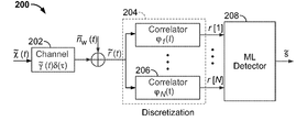
- the received signal, r(t), consists of a transmitted OFDM signal ⁇ tilde over ( ⁇ ) ⁇ (t) plus a single sinusoidal tone transmitted at frequency ⁇ c + ⁇ N +L/T s , both of which are distorted by the fading process ⁇ tilde over ( ⁇ ) ⁇ (t) due to the fading channel, and by the additive white Gaussian noise process n w (t) introduced at the receiver.
- ML maximum likelihood
- the estimated sequence ⁇ that is selected is of the minimum Euclidean distance to the received sequence r.
- the new receiver does not “reverse” the time-selective fading effects of the channel, but takes full advantage of the time variations to achieve the implicit diversity gain offered by the channel.
- FIG. 1 is a diagram illustrating an OFDM receiver implemented according to prior art.
- FIG. 2 is a diagram illustrating the optimal OFDM receiver implemented according to the invention.
- FIG. 3 is a diagram illustrating an optimal receiver process.
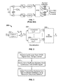
- FIG. 4 is a block diagram of the Discretizer 206 , also shown in FIG. 2 , which generates the sufficent statistics vector r for the optimal OFDM receiver.
- FIG. 6 is a finite-state machine model of the signal part of the received observable in equation (29).
- the received observable is input to the ML detector 208 shown in FIG. 2 .
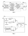
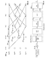
- FIG. 7 is a flow graph representation for two dominant memory elements of the finite-state machine model (shown in FIG. 6 ) of the signal part of the received observable in equation (29).
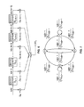
- FIG. 8 is a trellis diagram for two dominant memory elements of the finite-state machine model (shown in FIG. 6 ) of the signal part of the received observable in equation (29).
- This trellis diagram example illustrates the trellis search algorithm for ML detector 208 .
- FIG. 9 is a diagram illustrating an OFDM receiver where the DISCRETIZATION is implemented according to prior art and the ML detector is implemented according to the invention ML detector 208 as shown in 2 .
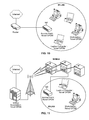
- FIG. 10 is a diagram illustrating an embodiment of a WLAN (Wireless Local Area Network) that may be implemented according to the invention.
- WLAN Wireless Local Area Network
- FIG. 11 is a system diagram illustrating an embodiment of a WIMAX (Worldwide Interoperability for Microwave Access) receiver system that is built according to the invention.
- WIMAX Worldwide Interoperability for Microwave Access
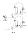
- FIG. 12 is a diagram illustrating an embodiment of a DSL (Digital Subscriber Line) communication system that may be implemented according to the invention.
- DSL Digital Subscriber Line
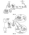
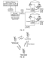
- FIG. 13 is a system diagram illustrating an embodiment of a DVB-T (Digital Video Broadcasting-Terrestrial) receiver system that is built according to the invention.
- DVB-T Digital Video Broadcasting-Terrestrial
- FIG. 14 is a system diagram illustrating an embodiment of HDTV (High Definition Television) broadcasting systems using DVB-T and DVB-H (Digital Video Broadcasting-Handheld) networks that are built according to the invention.
- HDTV High Definition Television
- DVB-T Digital Video Broadcasting-Handheld
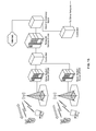
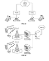
- FIG. 15 is system diagrams illustrating embodiment of uni-directional and bidirectional generic cellular communication systems built according to the invention.
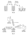
- FIG. 16 is a system diagram illustrating an embodiment of a uni-directional and bi-directional microwave communication system that is built according to the invention.
- FIG. 17 is a system diagram illustrating an embodiment of uni-directional and bidirectional point-to-point radio communication systems that are built according to the invention.
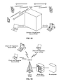
- FIG. 18 is a system diagram illustrating an embodiment of a unidirectional and bidirectional generic communication system that is built according to the invention.
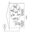
- FIG. 19 is a system diagram illustrating an embodiment of a one to many (multicast or one to a selected group of terminals or devices) or broadcast communication system that is built according to the invention.
- FIG. 20 is a system diagram illustrating an embodiment of UWB (Ultra-wideband) transceiver systems that are built according to the invention.
- UWB Ultra-wideband
- FIG. 21 is a system diagram illustrating an embodiment of an AC Power Line (Alternating Current Power Line) communication system that is built according to the invention.
- AC Power Line Alternating Current Power Line
- FIG. 22 is a system diagram illustrating an embodiment of a random ad-hoc or mesh network communication system that is built according to the invention.
- FIG. 23 is a system diagram illustrating an embodiment of a wireline communication system that is built according to the invention.
- FIG. 24 is a system diagram illustrating an embodiment of a Beyond 3G and/or future cellular communication system that is built according to the invention.
- FIG. 2 is a system diagram illustrating an embodiment of a wireless or wireline communication system that is built according to the invention.
- This wired or wireless network may include any number of networks including the Internet, proprietary networks, other wired networks and/or WANs (Wide Area Networks).
- the wireless communication “channel” may be viewed as not including multiple wireless hops in one embodiment.
- the receiver may also be implemented using terrestrial receivers such in a multi-hop embodiment.
- other receivers may exist that perform receiver operations in cooperation with each other.
- FIG. 4 provides further details of the discretization process 204 .
- the received signal r(t) is first time-limited or “windowed” by 302 to the duration of an OFDM symbol interval [nT s , (n+1)T s ], where n is an integer and designates the n th received OFDM symbol in the windowing function 302 .
- This windowing function 302 is performed for each OFDM symbol received in sequence.
- T s is the OFDM symbol duration interval.
- the optimality criterion for the optimal receiver is the minimum probability of OFDM symbol error.
- the former will be referred to as the optimal receiver and the latter as the suboptimal receiver.
- the receiver structures are described prior to presenting the performance analysis.
- FIG. 2 shows a block diagram of the optimal receiver 200 .
- This vector is an input to the ML detector 208 which is described in the next section.
- the correlation operation 206 can be easily implemented as exemplified in FIGS. 4 and 5 using 302 , 304 , 306 and modern, high-speed, digital signal processors (DSPs) or field programmable gate arrays (FPGAs).
- DSPs digital signal processors
- FPGAs field programmable gate arrays
- FIG. 9 A block diagram of a suboptimal receiver which employs prior art discretization and ML detector 208 (an aspect of this invention) is shown in FIG. 9 .
- the incoming OFDM signal ⁇ tilde over (r) ⁇ (t) is filtered through an ideal bandpass filter of equivalent lowpass bandwidth W/2.
- This observation vector is an input to an ML detector.
- ⁇ tilde over (y) ⁇ (t) has the form given in (7).
- the observables for the optimal receiver and suboptimal receiver are specified below.
- mn ⁇ ( l - 1 ) / L l / L ⁇ e j2 ⁇ ⁇ ( n - m ) ⁇ ⁇ ⁇ d ⁇
- s 2 ⁇ E b ⁇ b
- the received waveform ⁇ tilde over (r) ⁇ (t), in FIG. 9 is first processed by the suboptimal discretizer 902 to generate a suboptimal set of observables according to the following.
- the received waveform is ideal bandpass filtered prior to sampling to limit the noise.
- the equivalent lowpass filter bandwidth is W/2.
- the FFT is applied to obtain the suboptimal vector of observables y from the discrete time samples.
- the resulting ICI is now due to two different and independent causes—bandpass filtering and time variations in the channel.
- the observation vectors r and y are input to the ML detector.
- the output is the detected symbol vector with the maximum aposteriori probability (MAP).
- the A* algorithm [NeRaAu01: P. Nemeth, L. Rasmussen, and T. Aulin, “Maximum-likelihood detection of block coded CDMA using the A* algorithm,” in Proceedings of International Symposium on Information Theory, ISIT 2001, p. 88, June 2001. This article is incorporated by reference herein in its entirety.] is used to perform an optimal search to determine the optimal path in the tree.
- the optimal path corresponds to the most likely vector of data symbols (b[1] . . . b[N]) transmitted in the OFDM symbol.
- an appropriate metric and an heuristic function need to be defined for both the optimal and suboptimal OFDM receivers.
- the covariance matrix A is a symmetric and positive definite matrix.
- the distance (or cost) from the root node to node n is given by g k (n).
- the remaining distance from node n to the last node on the path b is given by h k (n).
- the algorithm starts with the root node in a list and terminates when the node to be expanded corresponds to the full N-length path through the search tree. This path specifies the ML vector b which minimized the function ⁇ (b). For every expanded node an evaluation function ⁇ k (n) must be calculated for its successors. Let h k (e) (n) be the underestimate of the remaining distance h k (n).
- the algorithm operates with a list of expansion-candidate nodes. At each iteration, the node with the smallest value for its evaluation function will be expanded to yield two child successor nodes as new candidate nodes through which to continue the search. The parent node will be removed from the list and its successors will be inserted in the list.
- An appropriate heuristic function remains to be defined.
- a better heuristic function can significantly reduce the number of nodes searched before the algorithm terminates and returns the ML vector. However, the computational load associated with evaluating the better heuristic function is increased.
- a candidate heuristic function to use is one based on constraint minimization techniques, as suggested in [NeRaAu01].
- the task of underestimating h k (n) by a chosen h k (e) (n) reduces to the task of underestimating q k (n) by a chosen q k (e) (n).
- n w ′′ y - 1 T s ⁇ C ⁇ ⁇ s .
- Equation (28) has the same form as equation (40).
- the A* algorithm for the case of the suboptimal receiver can be implemented in the very same way as for the case of the optimal receiver.
- the generated sequence is input to the integrator 306 in FIG. 4 , which performs the operation given by equation (16).
- the operation in (16) can be implemented using a Fast Fourier Transform as specified in equations (22) and (17) to (21).
- the superscript “ ⁇ 1” denotes matrix inverse.
- N ⁇ 1 shift registers For a received OFDM signal with N tones, there are N ⁇ 1 shift registers in its FSM model.
- the specific values in the N ⁇ 1 shift registers (or memory elements) form a numeric sequence, which represent the state of the system or of the FSM. A given unique sequence of values in the N ⁇ 1 memory elements specifies a unique state.
- a “state-group” be identified by a unique sequence of values in the dominant memory. elements.
- a given state belongs to a “state-group” when the given state's corresponding values in the dominant memory elements are the same as those defined for the “state-group”.
- states can be merged into a “super-state”, identified by the specific sequence of values in the dominant memory elements of the FSM.
- FIG. 7 shows a flow graph of a FSM with two dominate memory elements, where state sequences of length N ⁇ 1 are grouped into either one of the four “super-states”.
- FIG. 8 shows an example implementation of an approximate ML sequence detector.
- the possible output metrics are ((w) i+1 ⁇ f i+1 T b
- b[N] ⁇ 1 ) 2 +((w) i ⁇ f i T b
- the structure of an optimal OFDM receiver was compared to that of a suboptimal one in an AWGN channel and in a fast fading channel with AWGN.
- the structure of both receivers consists of a discretization block, with the time-continuous OFDM signal as the input and a vector of observables as an output, followed by an ML soft-decision detector, implemented using an A* optimal tree-search algorithm.
- the discretization block 204 for the optimal receiver generates the SS according to the principles of optimum signal detection, while the discretization block 902 for the suboptimum receiver samples the filtered continuous time waveform, followed by FFT to generate the observables which are suboptimal.
- the time-varying channel was assumed to be known at the receiver. Results show that both optimal and suboptimal systems benefit from the implicit diversity provided by the time variations of the fast fading channel.
- both the optimal and suboptimal receivers have the about the same complexity in terms of implementation.
- the optimal receiver significantly outperforms the suboptimal one.
Abstract
Detection of OFDM symbols generates an equivalent vector which represents the sufficient statistics (SS) which are subsequently processed using a maximum likelihood (ML) algorithm. The algorithms and implementations are described. Both examples of implementation using the A* (ML) algorithm and a near-ML trellis search algorithm for a time-varying finite state machine model of the received vector of SS are described.
Description
- This application claims the benefit of priority of U.S. Patent Application No. 60/783,058, for “OFDM In Fast Fading,” filed Mar. 17, 2006, which provisional patent application is incorporated by reference herein in its entirety.
- The invention relates generally to communication systems and, more particularly, it relates to receivers employed in the detection of signals and the recovery of the original transmitted information within such communication systems. Such communication systems include wireless, mobile wireless, and wireline: 4th Generation Cellular, 3rd Generation cellular long term evolution, wireless local area networks (WiFi), broadband fixed wireless access networks (WiMAX), mobile broadband wireless networks (mobile WiMAX), asynchronous digital subscriber lines (ADSL, VDSL), digital video broadcasting-terrestrial (DVB-T) and its extension DVB-Handheld (DVB-H), ultra wideband (UWB), alternating current (AC) power lines.
- Orthogonal Frequency Division Multiplexing (OFDM) is a digital transmission technique where a given channel bandwidth is divided into subchannels and individual digital signalling tones are transmitted over each subchannel concurrently in time. This transmission scheme has been an active area of research in many systems due to its resistance to multipath fading and potential for adaptive modulation where the number of tones as well as the modulation on each tone can be varied to optimize the aggregate data rate. The fact that the Discrete Fourier Transform (DFI) or Inverse Discrete Fourier Transform (IDFT), implemented using a Fast Fourier Transform algorithm, can be used to multiplex and demultiplex the signal tones was also one of the prime contributors to a high interest in this scheme.
- The use of using fast IDFT/DFT circuits is very convenient from the standpoint of system implementation. These digital circuits take as input a discrete sequence in frequency/time and generates as an output a discrete sequence in time/frequency respectively. A discretization process is needed to transform the received continuous time OFDM signal waveform to a corresponding discrete signal sequence. Conventional receivers or prior art, apply direct sampling of the continuous time OFDM waveforms to generate a corresponding discrete time sequence. This is accomplished via bandpass filtering of the received signal, followed by direct sampling by an Analog-to-Digital converter (ADC). These two operations are performed with or without first down converting the received signal from Radio Frequencies (RF) to Intemediate Frequencies (IF) and/or to Baseband Frequencies (BF). After the ADC, the a Discrete Fourier Transform is performed on the received signal samples using a Fast Fourier Transform (FFT) algorithm as shown in
FIG. 1 . - Apparently, there is no clear justification for the detection procedures where direct sampling of the incoming continuous time OFDM signal is performed as part of the detection process. It is well-known that the sampling procedure is lossy with respect to information. In one of more recent papers which implicitly deals with this problem, expressions are used for the demodulated signal obtained from a received OFDM signal which look very similar to those obtained by optimum detection procedures since he is using an infinite number of samples. However, using an infinite number of samples is not feasible in practice. Furthermore, this result does not provide a set of sufficient statistics since the signal's multiplicative time process, γ(t), is unknown and optimal filtering is not performed.
- The problem of optimal signal detection has been extensively analyzed by others. In order to obtain a maximal signal-to-noise ratio (SNR) as well as the sufficient statistics such that optimality is not sacrificed, correlation receivers or matched filters, consisting of a complete set of basis functions for the received signal, must be employed at receiver's front end. If we are able to select an appropriate orthonormal basis of functions for the received OFDM signal, after optimal detection of its coordinates in the selected signal space, we are able to optimally detect the transmitted symbols carried by the OFDM signal using a Maximum Aposteriori decision rule.
- Since the late 1950's, when the OFDM or Multitone transmission was invented, it was always believed that the optimal receiver is too complex to build, requiring banks of analog oscillators and banks of matched filters to de-multiplex or separate the signal tones of the received OFDM signal. For practical systems which employ 128 to 2048 signal tones, this was highly complex and costly. Thus, suboptimal receivers which employ sampling followed by FFT are considered an attractive alternative even today. The state of the art OFDM receivers today are suboptimal receivers that sample the continuous time signal and applies equalizers to remove the effects of fast fading.
- One important aspect of the invention described here provides a method to implement the optimal receiver for an OFDM signal transmitted over a variety of channel environments such as the wireless channel, as well as the wireline channel. It encompasses all data, digital voice, digital audio and digital video applications which employ the OFDM transmission technique. The implementation method for the optimal receiver employs a discretization process which provides the set of sufficient statistics (no loss of information) derived from the received continuous time OFDM signal. A Maximum Likelihood (ML) soft-decision algorithm can be used to detect the transmitted symbols from the set of sufficient statistics. The optimal discretization process has about the same complexity as the suboptimal discretization process, but the optimal provides a significant improvement in performance. The optimal discretization process is described in detail in the section entitled Optimal Receiver Functionality.
- Another important aspect of the invention is that the implicit diversity of the fading fading channel is used to provide performance gains for both the optimal and suboptimal OFDM systems. The approach used in prior art is to reverse the effects of the channel, such as the effects time-selective fading on the transmitted signal. Contrary to prior art, the new receiver makes use of the effects of the fast fading channel to improve detection performance, in terms of increased signal-to-noise ratio or in terms of transmitted higher data rates.
- Different from prior art, the new invention does not use analog-to-digial converters (ADC) to sample the received signal but employs a different method to generate a sequence that is a sufficient statistic. This sufficient statistic substantially contains all the information regarding the received continuous time waveform. Prior art, which employ ADC's, generate signal samples which are not a sufficient statistic. As a result, prior art receivers lose at least 3 decibels (dB) (or by factor of 2) in signal-to-noise power ratio over an additive white Gaussian noise channel (AWGN).
-
FIG. 4 is a block diagram of one implementation of a new receiver which generates the sufficient statistic, r[1], . . . ,r[N], from the received signal, r(t)={{tilde over (γ)}(t)({tilde over (χ)}(t)+√{square root over (2Eb/Ts)}ej2π(ƒ
N +L/Ts )t)ej2πƒc t}+nw(t), where{·} denotes the real part of the argument. The received signal, r(t), consists of a transmitted OFDM signal {tilde over (χ)}(t) plus a single sinusoidal tone transmitted at frequency ƒc+ƒN+L/Ts, both of which are distorted by the fading process {tilde over (γ)}(t) due to the fading channel, and by the additive white Gaussian noise process nw(t) introduced at the receiver. The sufficient statistic, r=[r[1], . . . , r[N]]T, is input to a maximum likelihood (ML)detector 208 which outputs an estimated transmitted sequence ŝ. The superscript “T” denotes vector transpose. The estimated sequence ŝ that is selected is of the minimum Euclidean distance to the received sequence r. Different from prior art, the new receiver does not “reverse” the time-selective fading effects of the channel, but takes full advantage of the time variations to achieve the implicit diversity gain offered by the channel. - The following figures illustrate some of the many different applications for which this invention can be used.
-
FIG. 1 is a diagram illustrating an OFDM receiver implemented according to prior art. -
FIG. 2 is a diagram illustrating the optimal OFDM receiver implemented according to the invention. -
FIG. 3 is a diagram illustrating an optimal receiver process. -
FIG. 4 is a block diagram of theDiscretizer 206, also shown inFIG. 2 , which generates the sufficent statistics vector r for the optimal OFDM receiver. -
FIG. 5 is a block diagram of theSequence Generator 304 for {ai, i=0, . . . , n−1}.Sequence Generator 304 also shown inFIG. 4 . -
FIG. 6 is a finite-state machine model of the signal part of the received observable in equation (29). The received observable is input to theML detector 208 shown inFIG. 2 . -
FIG. 7 is a flow graph representation for two dominant memory elements of the finite-state machine model (shown inFIG. 6 ) of the signal part of the received observable in equation (29). -
FIG. 8 is a trellis diagram for two dominant memory elements of the finite-state machine model (shown inFIG. 6 ) of the signal part of the received observable in equation (29). This trellis diagram example illustrates the trellis search algorithm forML detector 208. -
FIG. 9 is a diagram illustrating an OFDM receiver where the DISCRETIZATION is implemented according to prior art and the ML detector is implemented according to theinvention ML detector 208 as shown in 2. -
FIG. 10 is a diagram illustrating an embodiment of a WLAN (Wireless Local Area Network) that may be implemented according to the invention. -
FIG. 11 is a system diagram illustrating an embodiment of a WIMAX (Worldwide Interoperability for Microwave Access) receiver system that is built according to the invention. -
FIG. 12 is a diagram illustrating an embodiment of a DSL (Digital Subscriber Line) communication system that may be implemented according to the invention. -
FIG. 13 is a system diagram illustrating an embodiment of a DVB-T (Digital Video Broadcasting-Terrestrial) receiver system that is built according to the invention. -
FIG. 14 is a system diagram illustrating an embodiment of HDTV (High Definition Television) broadcasting systems using DVB-T and DVB-H (Digital Video Broadcasting-Handheld) networks that are built according to the invention. -
FIG. 15 is system diagrams illustrating embodiment of uni-directional and bidirectional generic cellular communication systems built according to the invention. -
FIG. 16 is a system diagram illustrating an embodiment of a uni-directional and bi-directional microwave communication system that is built according to the invention. -
FIG. 17 is a system diagram illustrating an embodiment of uni-directional and bidirectional point-to-point radio communication systems that are built according to the invention. -
FIG. 18 is a system diagram illustrating an embodiment of a unidirectional and bidirectional generic communication system that is built according to the invention. -
FIG. 19 is a system diagram illustrating an embodiment of a one to many (multicast or one to a selected group of terminals or devices) or broadcast communication system that is built according to the invention. -
FIG. 20 is a system diagram illustrating an embodiment of UWB (Ultra-wideband) transceiver systems that are built according to the invention. -
FIG. 21 is a system diagram illustrating an embodiment of an AC Power Line (Alternating Current Power Line) communication system that is built according to the invention. -
FIG. 22 is a system diagram illustrating an embodiment of a random ad-hoc or mesh network communication system that is built according to the invention. -
FIG. 23 is a system diagram illustrating an embodiment of a wireline communication system that is built according to the invention. -
FIG. 24 is a system diagram illustrating an embodiment of a Beyond 3G and/or future cellular communication system that is built according to the invention. - Various aspects of the invention may be found in any number of devices that detect OFDM or MIMO-OFDM transmitted signals. In some instances, the OFDM symbol detection is performed on signals whose code rate and/or modulation may vary as frequently as on an OFDM symbol by symbol basis.
- Diagrams of various system embodiments are provided below where any of the various aspects of the invention may be implemented. In general, any device that performs detection of OFDM signals may benefit from the invention.
-
FIG. 2 is a system diagram illustrating an embodiment of a wireless or wireline communication system that is built according to the invention. This wired or wireless network may include any number of networks including the Internet, proprietary networks, other wired networks and/or WANs (Wide Area Networks). For example, the wireless communication “channel” may be viewed as not including multiple wireless hops in one embodiment. The receiver may also be implemented using terrestrial receivers such in a multi-hop embodiment. In addition, other receivers may exist that perform receiver operations in cooperation with each other. - In some implementations, an optimal receiver process includes the steps of receiving a continuous time OFDM signal over a fading channel (210), deriving a set of sufficient statistics from the continuous time OFDM signal (212) and detecting transmitted symbols from the set of sufficient statistics using an ML detector (214) as depicted in
FIG. 3 . -
FIG. 4 provides further details of thediscretization process 204. The received signal r(t) is first time-limited or “windowed” by 302 to the duration of an OFDM symbol interval [nTs, (n+1)Ts], where n is an integer and designates the nth received OFDM symbol in thewindowing function 302. Thiswindowing function 302 is performed for each OFDM symbol received in sequence. Next, the windowed signal is processed by thesequence generator 304 to generate the sequence ai, i=0, . . . , n−1, defined by equations (20) and (21). In thesequence generator 304, (n−1) is defined to be (n−1)=Ts/Δt. Further details of a possible implementation of thesequence generator 304 is shown inFIG. 5 . Subsequently, the sufficient statistics, r[k], k=1, . . . , N, is generated by 306 from the input sequence ai, i=0, . . . , n−1 according to equation (22) which can be implemented using an FFT algorithm. - It is also noted that the methods described may also be performed within any of the appropriate system and/or apparatus designs (e.g., communication systems, communication devices, communication transceivers, communication receivers, and/or functionality described therein) that are depicted below without departing from the scope and spirit of the invention.
- In view of the detailed description of the invention and associated drawings above and below, other modifications and variations will now become apparent. It should also be apparent that such other modifications and variations may be effected without departing from the spirit and scope of the invention.
- A. OFDM System Model
- In its simplest form, when binary signalling (BPSK) is used, the complex envelope of the transmitted OFDM signal is given by
where ƒk=k/Ts is the central frequency of the kth subchannel, Ts is the OFDM symbol duration interval. The data symbols s[k]=√{square root over (Eb)}b[k], k=1, . . . , N, are all mutually independent and b[k]=±1. The total OFDM signal energy is - The OFDM signal is transmitted over a time-varying flat-fading channel and the complex envelope of the received OFDM signal can be written as
{tilde over (r)}(t)=γ(t){tilde over (χ)}(t)+ñ w(t), (4)
where γ(t) is a complex-valued Gaussian random process. The complex envelope of the additive white Gaussian noise (AWGN) has the following power spectrum
Φñw (ƒ)=N0,−∞<ƒ<∞ (5)
A Karhunen-Loéve expansion can be used to characterize the received signal part γ(t){tilde over (χ)}(t) where the eigenfunctions, {φk(t)}k=1 K, and corresponding eigenvalues, λ1, . . . , λK, are solutions to the integral equations
where Cr,i(t,u)=E[{tilde over (r)}(t){tilde over (r)}*(t)|{tilde over (χ)}i(t)], and {tilde over (χ)}i(t) is one of M=2N possible OFDM waveforms. The derivation of the eigenfunctions in closed-form is not trivial for the case of Rayleigh flat-fading channel. To partially overcome this difficulty a simplified model of the Rayleigh fading channel is proposed. We assume that it's possible to make a piecewise-constant approximation of the Gaussian random process γ(t) by {tilde over (γ)}(t), where
and where pl(t)=1 for (l−1)Tc≦t≦lTc and 0 elsewhere. It is assumed that (γ1 . . . γL)Tis a vector of independent and identically distributed (i.i.d.) complex-valued Gaussian random variables with zero mean and unit variance. It is also assumed L=Ts/Tc, where Tc is the coherence time of the channel. This model is a rough approximation because it approximates a time-continuous sample function (0≦t≦Ts) of the random process γ(t) by a strictly time-discontinuous, piecewise-constant function. However, it will help us to obtain some quick but important theoretical and numerical results for error performance. - We wish to compare the error performance of an optimal receiver for the transmitted OFDM signal to that of the conventional, FFT-based, OFDM receiver. The optimality criterion for the optimal receiver is the minimum probability of OFDM symbol error. In the subsequent text, the former will be referred to as the optimal receiver and the latter as the suboptimal receiver. The receiver structures are described prior to presenting the performance analysis.
-
FIG. 2 shows a block diagram of theoptimal receiver 200. Thediscretization process 204 inFIG. 2 generates the observation vector r=(r[1] . . . r[N])T. This vector is an input to theML detector 208 which is described in the next section. In practice, thecorrelation operation 206 can be easily implemented as exemplified inFIGS. 4 and 5 using 302, 304, 306 and modern, high-speed, digital signal processors (DSPs) or field programmable gate arrays (FPGAs). The computations employed in the 306 part of theDiscretizer 204 or more specifically, in the 306 aspect of thecorrelator 206 require basic multiplication and addition operations to perform the integration numerically. - A block diagram of a suboptimal receiver which employs prior art discretization and ML detector 208 (an aspect of this invention) is shown in
FIG. 9 . The incoming OFDM signal {tilde over (r)}(t) is filtered through an ideal bandpass filter of equivalent lowpass bandwidth W/2. The filtered signal is sampled using a sample-and-hold (S/H) circuit at time instants tn=nΔt, Δt=Ts/N, to generate the vector r′=(r′[1] . . . r′[N]). An N-point discrete Fourier transform (DFT) is performed on the vector r′ to obtain the observation vector y=(y[1] . . . y[N])T. This observation vector is an input to an ML detector. - Expressions for the observables r (for optimal receiver) and y (for suboptimal receiver) are presented for the case of a time-selective, flat-fading channel plus AWGN. We are assuming that {tilde over (r)}(t) is defined as in (4).
- For a time-selective flat-fading channel, {tilde over (y)}(t) has the form given in (7). The observables for the optimal receiver and suboptimal receiver are specified below.
- A. Optimum Receiver Functionality
- Define the set of basis functions {φk(t)}k=1 K, as
φk(t)={tilde over (γ)}(t)φk(t),K=N,k=1, . . . ,N (8)
where it's assumed that {tilde over (γ)}(t) is known and φk(t) is defined in (1) and (2). Then, projections of {tilde over (r)}(t) on the basis functions provide the SS for {tilde over (r)}(t). Note that the set {φk(t)}k=1 K is not orthonormal. The orthogonality of the OFDM signal tones at frequencies ƒk=k/Ts, k=1, . . . , N, is violated due to the time-varying multiplicative random process γ(t). This results in ICI among the data symbols. The vector of observables is
and r=(r[1] . . . r[N])T, s=(s[1] . . . s[N])T, n=(n[1] . . . n[N])T is the jointly Gaussian complex noise vector. The covariance matrices Al are Hermitian and |γl|, l=1, . . . , L, are i.i.d. Rayleigh random variables. Due to the ICI caused by a time-varying channel, the matrix A is not strictly diagonal.
B. Functionality/Implementation Description of the Optimal Discretization Process - The
discretization process 204 inFIG. 2 performs the following operation to generate the observables r[k], k=1, . . . , N:
Let yk(t)={tilde over (r)}(t)φ*k(t) and define the sequence yki as
for i=0, 1, . . . , n−1 where n−1 is the number of subintervals within [0, Ts] and Δt=Ts/(n−1) is the width of the subintervals. Thus, the function yk(t) evaluated at the endpoints of the interval [0, Ts] are yk0=yk(0) and yk(n−1)=yk(Ts). Applying a numerical integration rule such as the Trapezoidal Rule to equation (14) gives
The accuracy of the numerical integration increases as the width of the subintervals, Δt, decreases or equivalently, as the number of subintervals (n−1) increases. The sequence yki=yk(iΔt), i=0, 1, . . . , n−1 can be equivalently rewritten as
Using definitions from (17) to (19), the sum in (16) can be expressed as
Equation (22) can be interpreted as the Discrete Fourier Transform of the sequence ai, i=0, 1, . . . , n−1 with n>N. Thus, efficient algorithms such as the Fast Fourier Transform, can be employed inpart 306 to generate the sufficient statistics r[k], k=1, . . . , N as part of thediscretization process 204 inFIG. 2 for theoptimal receiver 200. Note that this is different from the suboptimal receiver described below which does not generate the sufficient statistics, but merely samples the time continuous function and thereby, throwing away information available in the received OFDM signal.
C. Suboptimum Receiver Functionality - The received waveform {tilde over (r)}(t), in
FIG. 9 , is first processed by thesuboptimal discretizer 902 to generate a suboptimal set of observables according to the following. The received waveform is ideal bandpass filtered prior to sampling to limit the noise. The equivalent lowpass filter bandwidth is W/2. The FFT is applied to obtain the suboptimal vector of observables y from the discrete time samples. The observables, y, at the output of thesuboptimal discretizer 902 of the suboptimal OFDM receiver are given by
and Ws=NΔƒ is fixed or is not varied. - The resulting ICI is now due to two different and independent causes—bandpass filtering and time variations in the channel.
- The observation vectors r and y, defined by (9) and (23) respectively, are input to the ML detector. The output is the detected symbol vector with the maximum aposteriori probability (MAP). The A* algorithm [NeRaAu01: P. Nemeth, L. Rasmussen, and T. Aulin, “Maximum-likelihood detection of block coded CDMA using the A* algorithm,” in Proceedings of International Symposium on Information Theory, ISIT 2001, p. 88, June 2001. This article is incorporated by reference herein in its entirety.] is used to perform an optimal search to determine the optimal path in the tree. The optimal path corresponds to the most likely vector of data symbols (b[1] . . . b[N]) transmitted in the OFDM symbol. To implement the A* algorithm, an appropriate metric and an heuristic function need to be defined for both the optimal and suboptimal OFDM receivers.
- A. The A * Algorithm for the Optimal Receiver
- The expression (9) for the vector of observables of the optimal OFDM receiver can be simplified to real valued vectors and matrix, i.e. r, s, nεRN, AεRN×N,
r=As+n, (28)
where E[nnT]=N0/2A. The covariance matrix A is a symmetric and positive definite matrix. The vector of observables (28) can be further transformed in the following way
F −T r=w=√{square root over (E b)}Fb+n w, (29)
where A=FTF, E[nwnw T]=N0/2I. Without loss of generality (WLOG) √{square root over (Eb)}=1 is assumed. The negative log-likelihood function, Λ(b), is defined as
Λ(b)=∥w−Fb∥ 2 (30)
=g k(n)+h k(n),0≦k≦N, (31)
where n is the node in the search tree at depth k through which the vector b is passing. - The distance (or cost) from the root node to node n is given by gk(n). The remaining distance from node n to the last node on the path b is given by hk(n). The algorithm starts with the root node in a list and terminates when the node to be expanded corresponds to the full N-length path through the search tree. This path specifies the ML vector b which minimized the function Λ(b). For every expanded node an evaluation function ƒk(n) must be calculated for its successors. Let hk (e)(n) be the underestimate of the remaining distance hk(n). The evaluation function ƒk(n) for node n is a sum of the current distance gk(n) and the heuristic function hk (e)(n) which yields
ƒk(n)=g k(n)+h k (e)(n),n=1, . . . ,2N,0≦k≦N. (32)
The algorithm operates with a list of expansion-candidate nodes. At each iteration, the node with the smallest value for its evaluation function will be expanded to yield two child successor nodes as new candidate nodes through which to continue the search. The parent node will be removed from the list and its successors will be inserted in the list. - An appropriate heuristic function remains to be defined. A better heuristic function can significantly reduce the number of nodes searched before the algorithm terminates and returns the ML vector. However, the computational load associated with evaluating the better heuristic function is increased.
- A candidate heuristic function to use is one based on constraint minimization techniques, as suggested in [NeRaAu01]. According to [NeRaAu01], the heuristic function can be written as
h k(n)=2q k(n)+c,0≦k≦N, (33)
where for the given node n at depth k, the quantity c is a constant and can be immediately calculated. Thus, the task of underestimating hk(n) by a chosen hk (e)(n) reduces to the task of underestimating qk(n) by a chosen qk (e)(n). - Define the notation u(k)=(u[1] . . . u[k]) and u(
k )=(u[k+1] . . . u[N]), 0≦k≦N. The problem of minimizing qk (e)(n) is treated as a box-constrained minimization problem: find the (N−k)−length vector u(k ) which lies in the box-constrained set −a(k )≦v(k )≦a(k ), a(k )={1}N−k, and minimizes
where A(k ),(k ) of dimension (N−k)×(N−k) is the submatrix in the bottom right of matrix A in (28) and
c T =F (k ),(k ) T(w (k ) −F (k ),(k ) b (k)). (35)
According to [NeRaAu01],
can be found using an iterative algorithm with polynomial complexity. This completes the description of an implementation of the A* algorithm for the optimal OFDM receiver, which is used for generating the numerical results in the next section.
B. The A * Algorithm for the Suboptimal Receiver - For any complex vector x and complex matrix X, define
- The expression (23) for the vector of observables of the suboptimal OFDM receiver was derived in the previous section, which implies
Since n″w is a vector of circularly-symmetric Gaussian random variables where ½E[n″wn″w †]=WN0/WsTsI, and assuming that the matrix {tilde over (C)} is non-singular, we can represent (39) in the equivalent form
The matrix {tilde over ({circumflex over (R)})}={tilde over (Ĉ)}†{tilde over (Ĉ)} is a positive definite and symmetric 2N×2N real matrix, {tilde over ({circumflex over (n)})} is a 2N×1 real noise vector with covariance
and ŝ is 2N×1 real signal vector. - Equation (28) has the same form as equation (40). Thus, the A* algorithm for the case of the suboptimal receiver can be implemented in the very same way as for the case of the optimal receiver.
-
FIG. 5 shows an example implementation of thesequence generator 304 for the sequence, ai, i=0, . . . , n−1. The generated sequence is input to theintegrator 306 inFIG. 4 , which performs the operation given by equation (16). The operation in (16) can be implemented using a Fast Fourier Transform as specified in equations (22) and (17) to (21). - The received signal vector of sufficient statistics, r, can be modelled as a time-varying finite state machine (FSM). Its linearly transformed version, w=(FT)−1r, given in equation (29), can similarly be modelled as a time-varying FSM, shown in
FIG. 6 . The superscript “−1” denotes matrix inverse. For a received OFDM signal with N tones, there are N−1 shift registers in its FSM model. The specific values in the N−1 shift registers (or memory elements) form a numeric sequence, which represent the state of the system or of the FSM. A given unique sequence of values in the N−1 memory elements specifies a unique state. - Let ƒik be the matrix element in the ith row and kth column of matrix F in equation (29). In
FIG. 6 , we associate a multiplier ƒik with the shift register, Dk, to the left of the multiplier for k=N−1, N−2, . . . , 1. Define D as the set with the smallest number of memory elements, whose corresponding associated multipliers ƒik have magnitudes all greater than those corresponding to memory elements not in the set D and satisfy
A memory element in the FSM is considered dominant and if it belongs to the set D. - Let a “state-group” be identified by a unique sequence of values in the dominant memory. elements. A given state belongs to a “state-group” when the given state's corresponding values in the dominant memory elements are the same as those defined for the “state-group”. In other words, states can be merged into a “super-state”, identified by the specific sequence of values in the dominant memory elements of the FSM. As an example,
FIG. 7 shows a flow graph of a FSM with two dominate memory elements, where state sequences of length N−1 are grouped into either one of the four “super-states”. - This grouping of states is permissible, results in a near-ML detector with an almost ML symbol error rate performance, and significantly reduces the complexity with respect to the ML detector when the number of dominant FSM memory elements is small. The dominant FSM memory elements with relatively large factors, |ƒik| contribute to the significant interchannel symbol interference. For the ith subchannel, this ICI is present in the observed symbol (w)i, defined as the ith component of vector w in equation (29).
FIG. 8 shows an example implementation of an approximate ML sequence detector. In this example, there are two dominant interfering subchannels as modelled by two memory elements giving rise to 4 possible “super-states” for binary signalling. Only the data symbols of the dominant interfering subchannels are used in defining the possible states. State transitions are triggered by the binary input, and the output is a partial sum of the ML metric given in equation (30). At subchannel i=N, the possible output metrics are ((w)i−fi Tb|b[N]=±1)2. At subchannel i=N−1, the possible output metrics are ((w)i+1−fi+1 Tb|b[N]=±1)2+((w)i−fi Tb|b[N]=±1,b[N−1]=±1)2, where as before (w)i denotes the ith component of vector w, fi T denotes the row vector in the ith row of the matrix F, and b is a column vector of transmitted data symbols with components b[k]=±1, k=1, . . . , N. - The structure of an optimal OFDM receiver was compared to that of a suboptimal one in an AWGN channel and in a fast fading channel with AWGN. The structure of both receivers consists of a discretization block, with the time-continuous OFDM signal as the input and a vector of observables as an output, followed by an ML soft-decision detector, implemented using an A* optimal tree-search algorithm. The
discretization block 204 for the optimal receiver generates the SS according to the principles of optimum signal detection, while thediscretization block 902 for the suboptimum receiver samples the filtered continuous time waveform, followed by FFT to generate the observables which are suboptimal. The time-varying channel was assumed to be known at the receiver. Results show that both optimal and suboptimal systems benefit from the implicit diversity provided by the time variations of the fast fading channel. - Finally, both the optimal and suboptimal receivers have the about the same complexity in terms of implementation. However, the optimal receiver significantly outperforms the suboptimal one.
Claims (24)
1. A method comprising:
deriving a set of statistics from a continuous time Orthogonal Frequency Division Multiplexing (OFDM) signal received on a fading channel; and
detecting one or more symbols using the set of statistics.
2. The method of claim 1 , where deriving the set of statistics further comprises:
deriving statistics that model time variations in the OFDM signal caused by the fading channel.
3. The method of claim 2 , where the time variations include a multiplicative time process of the OFDM signal.
4. The method of claim 1 , where deriving the set of statistics further comprises:
deriving the set of statistics using a descretization process that utilizes fading channel information associated with the continuous time OFDM signal.
5. The method of claim 1 , where detecting one or more symbols from the set of statistics further comprises:
detecting an estimated sequence of symbols from a vector of observables using a Maximum Likelihood (ML) detector.
6. The method of claim 5 , where detecting an estimated sequence of symbols from a vector of observables further comprises:
determining a Euclidean distance between the estimated sequence of symbols and the received OFDM signal in vector space; and
selecting the estimated sequence of symbols for output if the distance is a minimum Euclidean distance from the received signal.
7. The method of claim 5 , where detecting an estimated sequence of symbols from a vector of observables further comprises:
determining a vector of symbols with maximum aposteriori probability.
8. The method of claim 5 , where the vector of observables is modeled as a time-varying finite state machine.
9. The method of claim 5 , where the vector of observables, r[k], is generated based on an operation given by
where:
{tilde over (r)}(t) is the received OFDM signal;
φk T s (t) is a set of basis functions; and
Ts is the symbol duration period.
10. The method of claim 9 , wherein the operation is implemented using a frequency transform.
11. A system comprising:
a descretization module operable for receiving a continuous time Orthogonal Frequency Division Multiplexing (OFDM) signal on a fading channel, and for determining a set of statistics from the signal; and
a detector coupled to the descretization module and operable for detecting one or more symbols using the set of statistics.
12. The system of claim 11 , where the detector is a Maximum Likelihood (ML) detector.
13. The system of claim 11 , where the statistics model time variations in the OFDM signal caused by the fading channel.
14. The system of claim 11 , where the time variations include a multiplicative time process of the OFDM signal.
15. The system of claim 11 , where the set of statistics are derived using a descretization process that utilizes fading channel information associated with the continuous time OFDM signal.
16. The system of claim 11 , where the detector estimates a sequence of symbols from a vector of observables.
17. The system of claim 16 , where the detector determines a Euclidean distance between the estimated sequence of symbols and the received OFDM signal in vector space, and selects the estimated sequence of symbols for output if the distance is a minimum Euclidean distance from the received signal.
18. The system of claim 16 , where the vector of observables is modeled as a time-varying finite state machine.
19. The system of claim 16 , where the vector of observables, r[k], is generated based on an operation given by
k=1, . . . , N,
where:
{tilde over (r)}(t) is the received OFDM signal;
φk T s (t) is a set of basis functions; and
Ts is the symbol duration period.
20. The system of claim 19 , wherein the operation is implemented using a frequency transform.
21. A system comprising:
means for deriving a set of statistics from a continuous time Orthogonal Frequency Division Multiplexing (OFDM) signal received on a fading channel; and
means for detecting one or more symbols using the set of statistics.
22. A computer-readable medium having stored thereon instructions, which, when executed by a processor, causes the processor to perform operations comprising:
deriving a set of statistics from a continuous time Orthogonal Frequency Division Multiplexing (OFDM) signal received on a fading channel; and
detecting one or more symbols using the set of statistics.
23. A method comprising:
receiving a continuous time Orthogonal Frequency Division Multiplexing (OFDM) signal on a fading channel; and
correlating the continuous time OFDM signal with a set of basis functions to produce a set of statistics; and
detecting one or more symbols using the set of statistics.
24. The method of claim 23 , where the set of basis functions is complete for the received OFDM signal.
Priority Applications (1)
| Application Number | Priority Date | Filing Date | Title |
|---|---|---|---|
| US11/688,169 US8125883B2 (en) | 2006-03-17 | 2007-03-19 | OFDM in fast fading channel |
Applications Claiming Priority (2)
| Application Number | Priority Date | Filing Date | Title |
|---|---|---|---|
| US78305806P | 2006-03-17 | 2006-03-17 | |
| US11/688,169 US8125883B2 (en) | 2006-03-17 | 2007-03-19 | OFDM in fast fading channel |
Publications (2)
| Publication Number | Publication Date |
|---|---|
| US20070286063A1 true US20070286063A1 (en) | 2007-12-13 |
| US8125883B2 US8125883B2 (en) | 2012-02-28 |
Family
ID=38833831
Family Applications (1)
| Application Number | Title | Priority Date | Filing Date |
|---|---|---|---|
| US11/688,169 Expired - Fee Related US8125883B2 (en) | 2006-03-17 | 2007-03-19 | OFDM in fast fading channel |
Country Status (5)
| Country | Link |
|---|---|
| US (1) | US8125883B2 (en) |
| EP (1) | EP2002583A4 (en) |
| KR (2) | KR101383499B1 (en) |
| CN (1) | CN101529765A (en) |
| WO (1) | WO2007148232A2 (en) |
Cited By (10)
| Publication number | Priority date | Publication date | Assignee | Title |
|---|---|---|---|---|
| US20080134254A1 (en) * | 2006-12-04 | 2008-06-05 | Samsung Electronics Co., Ltd. | System and method for wireless communication of uncompressed high definition video data using a beamforming acquisition protocol |
| US20080130778A1 (en) * | 2006-12-04 | 2008-06-05 | Samsung Electronics Co., Ltd. | System and method for wireless communication of uncompressed high definition video data using a transfer matrix for beamforming estimation |
| US20080144751A1 (en) * | 2006-12-04 | 2008-06-19 | Samsung Electronics Co., Ltd. | System and method for wireless communication of uncompressed high definition video data using beambook-constructed beamforming signals |
| US20090046798A1 (en) * | 2007-08-13 | 2009-02-19 | Samsung Electronics Co., Ltd. | System and method for acquiring a training matrix for a breamforming acquisition protocol using a butson matrix |
| US20090141824A1 (en) * | 2006-12-04 | 2009-06-04 | Samsung Electronics Co., Ltd. | Method and system for generating candidate beamforming coeeficients for transmission of data over a wireless medium |
| US20110007851A1 (en) * | 2008-03-07 | 2011-01-13 | Imec | Method and device for multiple input-multiple output detection |
| US20120093198A1 (en) * | 2010-10-08 | 2012-04-19 | Texas Instruments Incorporated | Building, Transmitting, and Receiving Frame Structures in Power Line Communications |
| US9391839B2 (en) | 2014-06-11 | 2016-07-12 | Amplisine Labs, LLC | Ad hoc wireless mesh network |
| US20160365949A1 (en) * | 2015-06-15 | 2016-12-15 | Ching-Yih Tseng | Apparatus and Methods for Maximum Likelihood Symbol Detection in Communications Systems |
| US10182385B2 (en) | 2014-06-09 | 2019-01-15 | Site Pro, LLC | Multi-path wireless mesh networks |
Families Citing this family (12)
| Publication number | Priority date | Publication date | Assignee | Title |
|---|---|---|---|---|
| JP5458621B2 (en) * | 2009-03-19 | 2014-04-02 | 富士通株式会社 | Method, apparatus, and program for calculating simultaneous linear equations of sparse positive symmetric matrix |
| US9634690B2 (en) | 2010-09-30 | 2017-04-25 | Alcatel Lucent | Method and apparatus for arbitrary resolution video coding using compressive sampling measurements |
| US8644376B2 (en) * | 2010-09-30 | 2014-02-04 | Alcatel Lucent | Apparatus and method for generating compressive measurements of video using spatial and temporal integration |
| US9319578B2 (en) | 2012-10-24 | 2016-04-19 | Alcatel Lucent | Resolution and focus enhancement |
| US9344736B2 (en) | 2010-09-30 | 2016-05-17 | Alcatel Lucent | Systems and methods for compressive sense imaging |
| US8929456B2 (en) | 2010-09-30 | 2015-01-06 | Alcatel Lucent | Video coding using compressive measurements |
| US9398310B2 (en) | 2011-07-14 | 2016-07-19 | Alcatel Lucent | Method and apparatus for super-resolution video coding using compressive sampling measurements |
| US9600899B2 (en) | 2013-12-20 | 2017-03-21 | Alcatel Lucent | Methods and apparatuses for detecting anomalies in the compressed sensing domain |
| US9563806B2 (en) | 2013-12-20 | 2017-02-07 | Alcatel Lucent | Methods and apparatuses for detecting anomalies using transform based compressed sensing matrices |
| US9894324B2 (en) | 2014-07-15 | 2018-02-13 | Alcatel-Lucent Usa Inc. | Method and system for modifying compressive sensing block sizes for video monitoring using distance information |
| US11082880B2 (en) | 2017-10-27 | 2021-08-03 | Hewlett Packard Enterprise Development Lp | Adjusting data rates in wireless networks |
| CN112042161B (en) * | 2018-01-26 | 2023-09-26 | 加州理工学院 | System and method for communicating by modulating data at zero |
Citations (10)
| Publication number | Priority date | Publication date | Assignee | Title |
|---|---|---|---|---|
| US5671221A (en) * | 1995-06-14 | 1997-09-23 | Sharp Microelectronics Technology, Inc. | Receiving method and apparatus for use in a spread-spectrum communication system |
| US6154489A (en) * | 1998-03-30 | 2000-11-28 | Motorola, Inc. | Adaptive-rate coded digital image transmission |
| US20010055320A1 (en) * | 1994-12-15 | 2001-12-27 | Pierzga Wayne Francis | Multiplex communication |
| US20030156534A1 (en) * | 2000-08-25 | 2003-08-21 | Coulson Alan James | Communication system using OFDM |
| US6781951B1 (en) * | 1998-10-23 | 2004-08-24 | Koninklijke Philips Electronics N.V. | Radio communication system |
| US20040170228A1 (en) * | 2000-08-31 | 2004-09-02 | Nokia Corporation | Frequency domain partial response signaling with high spectral efficiency and low peak to average power ratio |
| US20050243943A1 (en) * | 2004-04-30 | 2005-11-03 | Richard Stirling-Gallacher | Equalising structure and method with maximum likelihood detection |
| US20060028977A1 (en) * | 2000-08-24 | 2006-02-09 | Seiichi Izumi | Communication device for receiving and transmitting OFDM signals in a wireless communication system |
| US20060141933A1 (en) * | 2004-12-23 | 2006-06-29 | Smee John E | Channel estimation for interference cancellation |
| US20060229017A1 (en) * | 2003-05-15 | 2006-10-12 | Peter Larsson | Interference cancellation in wireless relaying networks |
Family Cites Families (1)
| Publication number | Priority date | Publication date | Assignee | Title |
|---|---|---|---|---|
| US6654408B1 (en) * | 2000-10-27 | 2003-11-25 | Wisconsin Alumni Research Foundation | Method and system for multi-carrier multiple access reception in the presence of imperfections |
-
2007
- 2007-03-19 WO PCT/IB2007/002836 patent/WO2007148232A2/en active Application Filing
- 2007-03-19 EP EP07845236A patent/EP2002583A4/en not_active Withdrawn
- 2007-03-19 US US11/688,169 patent/US8125883B2/en not_active Expired - Fee Related
- 2007-03-19 CN CNA2007800159410A patent/CN101529765A/en active Pending
- 2007-03-19 KR KR1020087025276A patent/KR101383499B1/en not_active IP Right Cessation
- 2007-03-19 KR KR1020137025701A patent/KR20130119002A/en not_active Application Discontinuation
Patent Citations (11)
| Publication number | Priority date | Publication date | Assignee | Title |
|---|---|---|---|---|
| US20010055320A1 (en) * | 1994-12-15 | 2001-12-27 | Pierzga Wayne Francis | Multiplex communication |
| US20020114270A1 (en) * | 1994-12-15 | 2002-08-22 | Inmarsat Ltd | Multiplex communication |
| US5671221A (en) * | 1995-06-14 | 1997-09-23 | Sharp Microelectronics Technology, Inc. | Receiving method and apparatus for use in a spread-spectrum communication system |
| US6154489A (en) * | 1998-03-30 | 2000-11-28 | Motorola, Inc. | Adaptive-rate coded digital image transmission |
| US6781951B1 (en) * | 1998-10-23 | 2004-08-24 | Koninklijke Philips Electronics N.V. | Radio communication system |
| US20060028977A1 (en) * | 2000-08-24 | 2006-02-09 | Seiichi Izumi | Communication device for receiving and transmitting OFDM signals in a wireless communication system |
| US20030156534A1 (en) * | 2000-08-25 | 2003-08-21 | Coulson Alan James | Communication system using OFDM |
| US20040170228A1 (en) * | 2000-08-31 | 2004-09-02 | Nokia Corporation | Frequency domain partial response signaling with high spectral efficiency and low peak to average power ratio |
| US20060229017A1 (en) * | 2003-05-15 | 2006-10-12 | Peter Larsson | Interference cancellation in wireless relaying networks |
| US20050243943A1 (en) * | 2004-04-30 | 2005-11-03 | Richard Stirling-Gallacher | Equalising structure and method with maximum likelihood detection |
| US20060141933A1 (en) * | 2004-12-23 | 2006-06-29 | Smee John E | Channel estimation for interference cancellation |
Cited By (17)
| Publication number | Priority date | Publication date | Assignee | Title |
|---|---|---|---|---|
| US8259836B2 (en) | 2006-12-04 | 2012-09-04 | Samsung Electronics Co., Ltd. | Method and system for generating candidate beamforming coefficients for transmission of data over a wireless medium |
| US20080144751A1 (en) * | 2006-12-04 | 2008-06-19 | Samsung Electronics Co., Ltd. | System and method for wireless communication of uncompressed high definition video data using beambook-constructed beamforming signals |
| US20080134254A1 (en) * | 2006-12-04 | 2008-06-05 | Samsung Electronics Co., Ltd. | System and method for wireless communication of uncompressed high definition video data using a beamforming acquisition protocol |
| US8265177B2 (en) * | 2006-12-04 | 2012-09-11 | Samsung Electronics Co., Ltd. | System and method for wireless communication of uncompressed high definition video data using beambook-constructed beamforming signals |
| US20080130778A1 (en) * | 2006-12-04 | 2008-06-05 | Samsung Electronics Co., Ltd. | System and method for wireless communication of uncompressed high definition video data using a transfer matrix for beamforming estimation |
| US8040856B2 (en) | 2006-12-04 | 2011-10-18 | Samsung Electronics Co., Ltd. | System and method for wireless communication of uncompressed high definition video data using a beamforming acquisition protocol |
| US20090141824A1 (en) * | 2006-12-04 | 2009-06-04 | Samsung Electronics Co., Ltd. | Method and system for generating candidate beamforming coeeficients for transmission of data over a wireless medium |
| US20090046798A1 (en) * | 2007-08-13 | 2009-02-19 | Samsung Electronics Co., Ltd. | System and method for acquiring a training matrix for a breamforming acquisition protocol using a butson matrix |
| US20110007851A1 (en) * | 2008-03-07 | 2011-01-13 | Imec | Method and device for multiple input-multiple output detection |
| US8615057B2 (en) * | 2008-03-07 | 2013-12-24 | Imec | Method and device for multiple input-multiple output detection |
| US20120093198A1 (en) * | 2010-10-08 | 2012-04-19 | Texas Instruments Incorporated | Building, Transmitting, and Receiving Frame Structures in Power Line Communications |
| US8718115B2 (en) * | 2010-10-08 | 2014-05-06 | Texas Instruments Incorporated | Building, transmitting, and receiving frame structures in power line communications |
| US10182385B2 (en) | 2014-06-09 | 2019-01-15 | Site Pro, LLC | Multi-path wireless mesh networks |
| US9391839B2 (en) | 2014-06-11 | 2016-07-12 | Amplisine Labs, LLC | Ad hoc wireless mesh network |
| US20160365949A1 (en) * | 2015-06-15 | 2016-12-15 | Ching-Yih Tseng | Apparatus and Methods for Maximum Likelihood Symbol Detection in Communications Systems |
| US9942004B2 (en) * | 2015-06-15 | 2018-04-10 | Ching-Yih Tseng | Apparatus and methods for maximum likelihood symbol detection in communications systems |
| CN107925636A (en) * | 2015-06-15 | 2018-04-17 | 曾庆义 | It is used for the device and method of maximum likelihood symbol detection in communication system |
Also Published As
| Publication number | Publication date |
|---|---|
| WO2007148232A8 (en) | 2008-05-29 |
| CN101529765A (en) | 2009-09-09 |
| EP2002583A4 (en) | 2013-03-20 |
| WO2007148232A3 (en) | 2008-07-10 |
| KR101383499B1 (en) | 2014-04-08 |
| WO2007148232A2 (en) | 2007-12-27 |
| KR20130119002A (en) | 2013-10-30 |
| US8125883B2 (en) | 2012-02-28 |
| KR20080110624A (en) | 2008-12-18 |
| EP2002583A2 (en) | 2008-12-17 |
Similar Documents
| Publication | Publication Date | Title |
|---|---|---|
| US8125883B2 (en) | OFDM in fast fading channel | |
| US7848463B2 (en) | Adaptive time-filtering for channel estimation in OFDM system | |
| Kim et al. | An efficient frequency offset estimator for OFDM systems and its performance characteristics | |
| Li et al. | Subspace-based blind channel estimation for OFDM by exploiting virtual carriers | |
| JP4620277B2 (en) | Clustered OFDM with channel estimation | |
| US8300713B2 (en) | Preamble sequence detection and integral carrier frequency offset estimation method for OFDM/OFDMA wireless communication system | |
| Bang et al. | A coarse frequency offset estimation in an OFDM system using the concept of the coherence phase bandwidth | |
| JP2009532957A (en) | Channel estimation for rapidly dispersive fading channels | |
| US8275074B2 (en) | OFDM receiver for dispersive environment | |
| CN101268667B (en) | Estimation method of vector data sent, code element determining equipment and system | |
| JPWO2007020943A1 (en) | OFDM communication method | |
| EP2612476A1 (en) | Incremental joint detection of frequency domain symbols | |
| Tomba et al. | A model for the analysis of timing jitter in OFDM systems | |
| Hassan et al. | Variable pilot channels estimation based on blocktype and comb-type pilot arrangement in OFDM system | |
| Tai et al. | An overview of generalized frequency division multiplexing (GFDM) | |
| US20050073947A1 (en) | Channel estimator for a receiver and method of operation thereof | |
| CN105227504B (en) | A kind of channel estimation methods and system of MB-OFDM UWB systems | |
| Singh et al. | Block based channel Estimation Algorithms for OFDM-IEEE 802.16 e (Mobile WiMAX) system | |
| Zhang et al. | On practical inter-carrier interference cancellation techniques | |
| Hijazi et al. | OFDM Channel Parameters Estimation used for ICI Reduction in time-varying Multipath channels | |
| US20230396476A1 (en) | Radio transmission device and radio reception device | |
| Arrue et al. | Two coarse frequency acquisition algorithms for OFDM based IEEE 802.11 standards | |
| Chow et al. | WLC37-3: Diversity Benefits of OFDM in Fast Fading | |
| Curuk et al. | Simplified MAP estimator for OFDM systems under fading | |
| Ogundile et al. | Improved distance metric technique for deriving soft reliability information over Rayleigh Fading Channel |
Legal Events
| Date | Code | Title | Description |
|---|---|---|---|
| REMI | Maintenance fee reminder mailed | ||
| LAPS | Lapse for failure to pay maintenance fees | ||
| STCH | Information on status: patent discontinuation |
Free format text: PATENT EXPIRED DUE TO NONPAYMENT OF MAINTENANCE FEES UNDER 37 CFR 1.362 |
|
| FP | Lapsed due to failure to pay maintenance fee |
Effective date: 20160228 |