US20070192001A1 - Electronic control apparatus for vehicle and diagnosing method thereof - Google Patents
Electronic control apparatus for vehicle and diagnosing method thereof Download PDFInfo
- Publication number
- US20070192001A1 US20070192001A1 US11/655,269 US65526907A US2007192001A1 US 20070192001 A1 US20070192001 A1 US 20070192001A1 US 65526907 A US65526907 A US 65526907A US 2007192001 A1 US2007192001 A1 US 2007192001A1
- Authority
- US
- United States
- Prior art keywords
- abnormality
- control unit
- communication circuit
- determined
- communication
- Prior art date
- Legal status (The legal status is an assumption and is not a legal conclusion. Google has not performed a legal analysis and makes no representation as to the accuracy of the status listed.)
- Granted
Links
Images


Classifications
-
- F—MECHANICAL ENGINEERING; LIGHTING; HEATING; WEAPONS; BLASTING
- F02—COMBUSTION ENGINES; HOT-GAS OR COMBUSTION-PRODUCT ENGINE PLANTS
- F02D—CONTROLLING COMBUSTION ENGINES
- F02D41/00—Electrical control of supply of combustible mixture or its constituents
- F02D41/24—Electrical control of supply of combustible mixture or its constituents characterised by the use of digital means
- F02D41/26—Electrical control of supply of combustible mixture or its constituents characterised by the use of digital means using computer, e.g. microprocessor
-
- B—PERFORMING OPERATIONS; TRANSPORTING
- B60—VEHICLES IN GENERAL
- B60W—CONJOINT CONTROL OF VEHICLE SUB-UNITS OF DIFFERENT TYPE OR DIFFERENT FUNCTION; CONTROL SYSTEMS SPECIALLY ADAPTED FOR HYBRID VEHICLES; ROAD VEHICLE DRIVE CONTROL SYSTEMS FOR PURPOSES NOT RELATED TO THE CONTROL OF A PARTICULAR SUB-UNIT
- B60W50/00—Details of control systems for road vehicle drive control not related to the control of a particular sub-unit, e.g. process diagnostic or vehicle driver interfaces
- B60W50/04—Monitoring the functioning of the control system
-
- F—MECHANICAL ENGINEERING; LIGHTING; HEATING; WEAPONS; BLASTING
- F01—MACHINES OR ENGINES IN GENERAL; ENGINE PLANTS IN GENERAL; STEAM ENGINES
- F01L—CYCLICALLY OPERATING VALVES FOR MACHINES OR ENGINES
- F01L1/00—Valve-gear or valve arrangements, e.g. lift-valve gear
- F01L1/34—Valve-gear or valve arrangements, e.g. lift-valve gear characterised by the provision of means for changing the timing of the valves without changing the duration of opening and without affecting the magnitude of the valve lift
-
- F—MECHANICAL ENGINEERING; LIGHTING; HEATING; WEAPONS; BLASTING
- F01—MACHINES OR ENGINES IN GENERAL; ENGINE PLANTS IN GENERAL; STEAM ENGINES
- F01L—CYCLICALLY OPERATING VALVES FOR MACHINES OR ENGINES
- F01L13/00—Modifications of valve-gear to facilitate reversing, braking, starting, changing compression ratio, or other specific operations
- F01L13/0015—Modifications of valve-gear to facilitate reversing, braking, starting, changing compression ratio, or other specific operations for optimising engine performances by modifying valve lift according to various working parameters, e.g. rotational speed, load, torque
- F01L13/0021—Modifications of valve-gear to facilitate reversing, braking, starting, changing compression ratio, or other specific operations for optimising engine performances by modifying valve lift according to various working parameters, e.g. rotational speed, load, torque by modification of rocker arm ratio
- F01L13/0026—Modifications of valve-gear to facilitate reversing, braking, starting, changing compression ratio, or other specific operations for optimising engine performances by modifying valve lift according to various working parameters, e.g. rotational speed, load, torque by modification of rocker arm ratio by means of an eccentric
-
- F—MECHANICAL ENGINEERING; LIGHTING; HEATING; WEAPONS; BLASTING
- F02—COMBUSTION ENGINES; HOT-GAS OR COMBUSTION-PRODUCT ENGINE PLANTS
- F02D—CONTROLLING COMBUSTION ENGINES
- F02D41/00—Electrical control of supply of combustible mixture or its constituents
- F02D41/22—Safety or indicating devices for abnormal conditions
-
- F—MECHANICAL ENGINEERING; LIGHTING; HEATING; WEAPONS; BLASTING
- F01—MACHINES OR ENGINES IN GENERAL; ENGINE PLANTS IN GENERAL; STEAM ENGINES
- F01L—CYCLICALLY OPERATING VALVES FOR MACHINES OR ENGINES
- F01L1/00—Valve-gear or valve arrangements, e.g. lift-valve gear
- F01L1/02—Valve drive
- F01L1/04—Valve drive by means of cams, camshafts, cam discs, eccentrics or the like
- F01L1/047—Camshafts
- F01L1/053—Camshafts overhead type
- F01L2001/0537—Double overhead camshafts [DOHC]
-
- F—MECHANICAL ENGINEERING; LIGHTING; HEATING; WEAPONS; BLASTING
- F01—MACHINES OR ENGINES IN GENERAL; ENGINE PLANTS IN GENERAL; STEAM ENGINES
- F01L—CYCLICALLY OPERATING VALVES FOR MACHINES OR ENGINES
- F01L13/00—Modifications of valve-gear to facilitate reversing, braking, starting, changing compression ratio, or other specific operations
- F01L13/0015—Modifications of valve-gear to facilitate reversing, braking, starting, changing compression ratio, or other specific operations for optimising engine performances by modifying valve lift according to various working parameters, e.g. rotational speed, load, torque
- F01L13/0063—Modifications of valve-gear to facilitate reversing, braking, starting, changing compression ratio, or other specific operations for optimising engine performances by modifying valve lift according to various working parameters, e.g. rotational speed, load, torque by modification of cam contact point by displacing an intermediate lever or wedge-shaped intermediate element, e.g. Tourtelot
- F01L2013/0073—Modifications of valve-gear to facilitate reversing, braking, starting, changing compression ratio, or other specific operations for optimising engine performances by modifying valve lift according to various working parameters, e.g. rotational speed, load, torque by modification of cam contact point by displacing an intermediate lever or wedge-shaped intermediate element, e.g. Tourtelot with an oscillating cam acting on the valve of the "Delphi" type
-
- F—MECHANICAL ENGINEERING; LIGHTING; HEATING; WEAPONS; BLASTING
- F01—MACHINES OR ENGINES IN GENERAL; ENGINE PLANTS IN GENERAL; STEAM ENGINES
- F01L—CYCLICALLY OPERATING VALVES FOR MACHINES OR ENGINES
- F01L2800/00—Methods of operation using a variable valve timing mechanism
-
- F—MECHANICAL ENGINEERING; LIGHTING; HEATING; WEAPONS; BLASTING
- F01—MACHINES OR ENGINES IN GENERAL; ENGINE PLANTS IN GENERAL; STEAM ENGINES
- F01L—CYCLICALLY OPERATING VALVES FOR MACHINES OR ENGINES
- F01L2800/00—Methods of operation using a variable valve timing mechanism
- F01L2800/12—Fail safe operation
-
- F—MECHANICAL ENGINEERING; LIGHTING; HEATING; WEAPONS; BLASTING
- F01—MACHINES OR ENGINES IN GENERAL; ENGINE PLANTS IN GENERAL; STEAM ENGINES
- F01L—CYCLICALLY OPERATING VALVES FOR MACHINES OR ENGINES
- F01L2820/00—Details on specific features characterising valve gear arrangements
- F01L2820/03—Auxiliary actuators
- F01L2820/032—Electric motors
Definitions
- the present invention relates to an electronic control apparatus adapted for a vehicle, not exclusively but preferably a car, and provided with a plurality of control units and a communication circuit providing a connection for communication among the control units.
- Japanese Unexamined Patent Publication No. 2002-314632 discloses a system in which data communication is performed among a plurality of control units. Each of the control units detects whether or not a communication abnormality occurs on the basis of the cycles of received data and, when occurrence of the communication abnormality is detected, each of the control units executes a fail-safe mode.
- each of the control units diagnoses an own reception state but cannot diagnose a reception state of the associated control unit or units.
- the fail-safe mode cannot be properly executed with respect to a reception abnormality of the other associated control unit or units, and there is such a possibility that controllability might largely deteriorate.
- An object of the present invention is to determine occurrence of a communication abnormality more accurately and to execute a fail-safe mode more properly with respect to the communication abnormality.
- an electronic control apparatus adapted for a vehicle, and incorporating therein a plurality of control units associable in communication with one another and a communication circuit providing a connection for communication among the control units, each control unit being configured to diagnose an abnormality in data reception and transmit the diagnosis result to other control unit in association for communication, thereby to diagnose an abnormality that occurs in the communication circuit on the basis of both the diagnosis result of the control unit per se and a diagnosis result transmitted from the associated control unit in communication.
- a diagnosing method of an electronic control apparatus for a vehicle having a plurality of control units associable in communication with one another and a communication circuit that connects the plurality of control units to one another for communication among the control units.
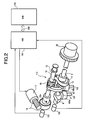
- FIG. 1 is a system diagram of a vehicular engine to which the present invention is applied;
- FIG. 2 is a perspective view showing the details of a variable lift mechanism illustrated in FIG. 1 ;
- FIG. 3 is a side view showing the details of the variable lift mechanism illustrated in FIG. 1 ;
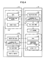
- FIG. 4 is a block diagram showing functions of a control unit illustrated in FIG. 1 ;
- FIG. 5 is a flowchart showing diagnostic control and a fail-safe mode common to the control units
- FIG. 6 is a flowchart showing diagnosis and the fail-safe mode performed by a control unit for controlling the variable lift mechanism.
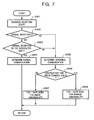
- FIG. 7 is a flowchart showing diagnosis and the fail-safe mode performed by a control unit for controlling an electronically-controlled throttle.
- FIG. 1 is a system configuration diagram of a vehicular engine, e.g., a car engine.
- an electronically-controlled throttle 104 for driving a throttle valve 103 b by a throttle motor 103 a is disposed in an intake pipe 102 of an engine (gasoline internal combustion engine) 101 .
- Air is sucked into a combustion chamber 106 via electronically-controlled throttle 104 and an intake valve 105 .
- Fuel injection valve 131 injects fuel (gasoline), an amount of which is proportional to valve open time.
- the fuel is ignited and combusted in combustion chamber 106 due to a spark ignition by a not-shown spark plug.
- Exhaust gas in combustion chamber 106 is exhausted via an exhaust valve 107 , purified by a front catalytic converter 108 and a rear catalytic converter 109 , and the resultant gas is exhausted to the atmosphere.
- Exhaust valve 107 is driven so as to be opened/closed by a cam 111 provided on an exhaust-side cam shaft 110 , with maintaining a predetermined valve lift amount, a valve operation angle, and a valve timing.
- intake valve 105 is adjusted by a variable lift mechanism 112 so that the valve lift amount and the operation angle vary continuously.
- An engine control unit (ECU) 114 incorporating therein a microcomputer controls fuel ejection valve 131 , a power transistor for a spark coil, and electronically-controlled throttle 104 by a computing process according to a pre-stored program.
- VCU valve control unit
- Engine control unit 114 and valve control unit 141 are arranged to perform necessary controlling motions in associate with each other and are, therefore, connected to one another via a communication circuit 250 to carry out diverse communications therebetween.
- a target lift amount computed by engine control unit 114 is transmitted to valve control unit 141 and, on the other hand, data indicating an actual valve lift amount is transmitted from valve control unit 141 to engine control unit 114 .
- detection signals are inputted from an air flow meter 115 for detecting an intake air amount of engine 101 , an accelerator pedal sensor 116 for detecting a stroke amount of an accelerator pedal operated by a driver of the vehicle, a crank angle sensor 117 for detecting a section to be detected, which is provided on a signal plate supported by a crankshaft 120 and for outputting a crank angle signal at each of reference rotational positions of crankshaft 120 , a throttle sensor 118 for detecting an opening angle TVO of throttle valve 103 b , a water temperature sensor 119 for detecting temperature of cooling water of engine 101 , a cam angle sensor 132 for detecting an intended section for detection, which is provided on a signal plate supported by an intake valve drive shaft 3 , and for outputting a cam angle signal at each of reference rotational positions of intake valve drive shaft 3 , and an intake pressure sensor 134 for detecting an intake manifold pressure on the downstream of throttle valve 103 b and on the upstream side of intake valve 105 .
- FIG. 2 is a perspective view showing the structure of variable lift mechanism 112 .
- a pair of intake valves 105 is provided for each of the cylinders, and intake valve drive shaft 3 rotatably driven by crankshaft 120 is supported along a cylinder line direction above intake valves 105 .
- An oscillating cam 4 in contact with a valve lifter 105 a of an associated one of intake valves 105 and opening/closing this intake valve 105 is mounted to be fit onto intake valve drive shaft 3 so as to be relatively rotatable.
- variable lift mechanism 112 for continuously changing the operation angle and the valve lift amount of intake valve 105 is provided.
- variable valve timing mechanism 20 is provided which continuously changes the center phase of the operation angle of intake valve 105 by changing the rotation phase of intake valve drive shaft 3 relative to crankshaft 120 .
- variable valve timing mechanism 20 is controlled by engine control unit 114 in the present embodiment, valve control unit 141 may control variable lift mechanism 112 and variable valve timing mechanism 20 .
- variable lift mechanism 112 has a circular drive cam 11 eccentrically and fixedly provided on intake valve drive shaft 3 , a ring-shaped link 12 fit onto drive cam 11 so as to be relatively rotatable, a control shaft 13 extending in the cylinder line direction in almost parallel with intake valve drive shaft 3 , a circular control cam 14 eccentrically and fixedly provided on control shaft 13 , a rocker arm 15 relatively rotatably fit onto control cam 14 to have one end thereof which is coupled to the tip of ring-shaped link 12 , and a rod-shaped link 16 coupled to the other end of rocker arm 15 and oscillating cam 4 .
- Control shaft 13 is rotated by a motor 17 via a gear train 18 .
- a stopper 13 a integrally provided with control shaft 13 and coming into contact with a suitably arranged stationary side (not illustrated in FIG. 2 ), control shaft 13 is prevented from further turning to a lift amount reduction side more than an angle position corresponding to a preset minimum lift position.
- control cam 14 By changing the rotation angle of control shaft 13 by driving motor 17 , the axis position of control cam 14 as the rocking center of rocker arm 15 changes, and the posture of oscillating cam 4 changes.
- a detection signal from an angle sensor 133 for detecting the rotation angle of control shaft 13 is inputted to valve control unit 141 .
- Valve control unit 141 feedback-controls a flow amount of an electric current to motor 17 on the basis of a detection result of angle sensor 133 in order to rotate control shaft 13 to a target angle position corresponding to a target lift amount transmitted from engine control unit 114 .
- a power-source relay provided for motor 17 is designed to be capable of being on/off-controlled independently by each of engine control unit 114 and valve control unit 141 .
- data of the target lift amount and data of the actual rotation angle of control shaft 13 are transmitted and/or received via communication circuit 250 provided between engine control unit 114 and valve control unit 141 .
- communication circuit 250 provided between engine control unit 114 and valve control unit 141 .
- control unit 114 and valve control unit 141 As shown in FIG. 4 , diagnosis of a communication abnormality and a fail-safe mode are executed.
- respective engine control unit (ECU) 114 and valve control unit (VCU) 141 that are mutually associated with one another for performing required controlling motions are provided with transmission units 114 a , 141 a and abnormal-state-determining units 114 b , 141 b , respectively.
- Each of transmission units 114 a , 141 a includes a transmitting unit 201 that transmits data to be used for reception check to the associated side, a transmitting unit 202 for transmitting a determination result obtained by its own abnormal-state-determining units 114 b , 141 b to the associated side, and a transmitting unit 203 that transmits therefrom data of a target lift amount or an actual lift amount.
- Each of abnormal-state-determining units 114 b , 141 b includes: a reception check unit 205 for receiving data outputted from transmitting unit 201 on the associated side, diagnosing a communication state based on communication cycles of the reception data, and outputting a diagnosis result to transmitting unit 202 and a diagnosing unit 206 which will be described later; and diagnosing unit 206 that reads a diagnosis result transmitted from transmitting unit 202 of the associated side and a diagnosis result of its own reception check unit 205 , and diagnosing an abnormal state of communication circuit 250 .
- diagnosing unit 206 determines that an abnormality has occurred in communication circuit 250 .
- Each of engine control unit 114 and valve control unit 141 when any one of or both of diagnosing units 206 determines or determine that an abnormality has occurred in communication circuit 250 , executes the fail-safe mode for itself.
- variable lift mechanism 112 is controlled on the basis of a target lift amount which is pre-stored for the fail-safe mode.
- variable lift mechanism 112 is controlled on the basis of the lift amount for the fail-safe mode, and then controls the opening angle of throttle valve 103 b so as to obtain a target intake air amount under the target lift amount for the fail-safe mode. That is to say, the fail-safe mode of the engine control unit 114 is executed in the described manner. As a result, even if any abnormality occurs in communication circuit 250 , an intake air amount can be controlled in accordance with a request, and considerable deterioration in drivability can be avoided.
- valve control unit 141 it is necessary to interrupt current flow to motor 17 of variable lift mechanism 112 to thereby control variable lift mechanism 112 to the minimum lift amount.
- variable lift mechanism 112 is controlled on the basis of the target lift amount for the fail-safe mode and, on the other hand, the opening angle of the throttle valve can be controlled on such a condition that variable lift mechanism 112 has been controlled to the target lift amount for the fail-safe mode.
- the flowchart of FIG. 5 relates to determination of an abnormality in communication circuit 250 (network) and the fail-safe mode performed by engine control unit 114 and valve control unit 141 .
- step S 101 data transmitted from the associated side is received, thereby executing determinination of reception state.
- the communication state is diagnosed from cycles of communication for mutually communicating reception data.
- step S 102 it is determined whether a result of diagnosis of the reception state in the step S 101 is normal or abnormal.
- step S 102 When it is determined in the step S 102 that the reception state is normal, the control unit proceeds to step S 103 where whether a result of diagnosis of the reception state on the associated side transmitted from the associated side is normal or not is determined.
- control unit proceeds to step S 104 where it is determined that communication circuit 250 is normal.
- step S 102 when it is determined in the step S 102 that the reception result of the control unit itself is abnormal or when it is determined in the step S 103 that the diagnosis result of the reception result on the associated side is abnormal, the control unit proceeds to step S 105 .
- step S 105 it is determined that an abnormality has occurred in communication circuit 250 .
- step S 106 When an abnormality in communication circuit 250 is determined, in the following step S 106 , a preset fail-safe mode is executed.
- variable lift mechanism 112 is controlled on the basis of the target lift amount which is pre-stored for the fail-safe mode.
- variable lift mechanism 112 is controlled to the lift amount for the fail-safe mode
- the opening angle of throttle valve 103 b is controlled so as to obtain the target intake air amount under the target lift amount for the fail-safe mode.
- Abnormalities of communication circuit 250 include a relatively minor abnormality such as noise to a serious abnormality such as disconnection of communication circuit 250 . According to the degree of an abnormality, the fail-safe mode can be switched.
- valve control unit 141 switches the content of the fail-safe mode in accordance with the degree of an abnormality in communication circuit 250 .
- steps S 201 to S 205 processes similar to those in the steps S 101 to S 105 are performed by the valve control unit 141 .
- valve control unit 141 proceeds to step S 206 and determines whether or not continuation time in which determination of the abnormality occurrence in communication circuit 250 continues exceeds a predetermined value.
- valve control unit 141 determines that an abnormality in communication circuit 250 is minor and proceeds to step S 207 .
- variable lift mechanism 112 is controlled on the basis of the target lift amount which is pre-stored for the fail-safe mode.
- valve control unit 141 determines that an abnormality of communication circuit 250 is serious and proceeds to step S 208 .
- step S 208 motor 17 for driving variable lift mechanism 112 is forcedly turned off, and variable lift mechanism 112 returns to the initial position (minimum lift position).
- the degree of an abnormality in communication circuit 250 can be determined not only by continuation time of the abnormality determination and the number of times of abnormality determination but also by an error with respect to a reference value of communication cycles.
- the method of determining the degree of an abnormality is not limited.
- the flowchart of FIG. 7 shows an example in which engine control unit 114 switches the fail-safe mode in accordance with the degree of an abnormality in communication circuit 250 .
- steps S 301 to S 305 processes similar to those in the steps S 101 to S 105 are performed.
- step S 305 When it is determined in step S 305 that an abnormality has occurred in communication circuit 250 , engine control unit 114 proceeds to step S 306 and determines whether or not continuation time (or the number of times) in which determination of abnormality occurrence in communication circuit 250 exceeds a predetermined value.
- engine control unit 114 determines that an abnormality in communication circuit 250 is minor and proceeds to step S 307 .
- the throttle position is controlled according to the requested intake air amount.
- engine control unit 114 determines that an abnormality in communication circuit 250 is serious and proceeds to step S 308 .
- step S 308 motor 17 for driving variable lift mechanism 112 is forcedly turned off, so that variable lift mechanism 112 returns to the initial position (minimum lift position) and, on the assumption that variable lift mechanism 112 has returned to the initial position (minimum lift position), the throttle position is controlled according to the requested intake air amount.
- the degree of an abnormality in communication circuit 250 which is minor or serious, is determined and the fail-safe mode is switched accordingly.
- the fail-safe mode is switched accordingly.
Abstract
Description
- 1. Field of the Invention
- The present invention relates to an electronic control apparatus adapted for a vehicle, not exclusively but preferably a car, and provided with a plurality of control units and a communication circuit providing a connection for communication among the control units.
- 2. Description of the Related Art
- Japanese Unexamined Patent Publication No. 2002-314632 discloses a system in which data communication is performed among a plurality of control units. Each of the control units detects whether or not a communication abnormality occurs on the basis of the cycles of received data and, when occurrence of the communication abnormality is detected, each of the control units executes a fail-safe mode.
- In the conventional diagnosis of communication abnormality, each of the control units diagnoses an own reception state but cannot diagnose a reception state of the associated control unit or units.
- Consequently, the fail-safe mode cannot be properly executed with respect to a reception abnormality of the other associated control unit or units, and there is such a possibility that controllability might largely deteriorate.
- An object of the present invention is to determine occurrence of a communication abnormality more accurately and to execute a fail-safe mode more properly with respect to the communication abnormality.
- To achieve the object, in accordance with the present invention, there is provided an electronic control apparatus adapted for a vehicle, and incorporating therein a plurality of control units associable in communication with one another and a communication circuit providing a connection for communication among the control units, each control unit being configured to diagnose an abnormality in data reception and transmit the diagnosis result to other control unit in association for communication, thereby to diagnose an abnormality that occurs in the communication circuit on the basis of both the diagnosis result of the control unit per se and a diagnosis result transmitted from the associated control unit in communication.
- In accordance with another aspect of the present invention, there is provided a diagnosing method of an electronic control apparatus for a vehicle, having a plurality of control units associable in communication with one another and a communication circuit that connects the plurality of control units to one another for communication among the control units.
- The other objects, features, and advantages of this invention will become understood from the following description with reference to the accompanying drawings.
-
FIG. 1 is a system diagram of a vehicular engine to which the present invention is applied; -
FIG. 2 is a perspective view showing the details of a variable lift mechanism illustrated inFIG. 1 ; -
FIG. 3 is a side view showing the details of the variable lift mechanism illustrated inFIG. 1 ; -
FIG. 4 is a block diagram showing functions of a control unit illustrated inFIG. 1 ; -
FIG. 5 is a flowchart showing diagnostic control and a fail-safe mode common to the control units; -
FIG. 6 is a flowchart showing diagnosis and the fail-safe mode performed by a control unit for controlling the variable lift mechanism; and -
FIG. 7 is a flowchart showing diagnosis and the fail-safe mode performed by a control unit for controlling an electronically-controlled throttle. - Embodiments of the present invention will be described hereinbelow.
-
FIG. 1 is a system configuration diagram of a vehicular engine, e.g., a car engine. - Referring to
FIG. 1 , an electronically-controlledthrottle 104 for driving athrottle valve 103 b by athrottle motor 103 a is disposed in anintake pipe 102 of an engine (gasoline internal combustion engine) 101. - Air is sucked into a
combustion chamber 106 via electronically-controlledthrottle 104 and anintake valve 105. - An
intake port 130 of each of cylinders is provided with afuel injection valve 131.Fuel injection valve 131 injects fuel (gasoline), an amount of which is proportional to valve open time. - The fuel is ignited and combusted in
combustion chamber 106 due to a spark ignition by a not-shown spark plug. - Exhaust gas in
combustion chamber 106 is exhausted via anexhaust valve 107, purified by a frontcatalytic converter 108 and a rearcatalytic converter 109, and the resultant gas is exhausted to the atmosphere. -
Exhaust valve 107 is driven so as to be opened/closed by acam 111 provided on an exhaust-side cam shaft 110, with maintaining a predetermined valve lift amount, a valve operation angle, and a valve timing. - On the other hand,
intake valve 105 is adjusted by avariable lift mechanism 112 so that the valve lift amount and the operation angle vary continuously. - An engine control unit (ECU) 114 incorporating therein a microcomputer controls
fuel ejection valve 131, a power transistor for a spark coil, and electronically-controlledthrottle 104 by a computing process according to a pre-stored program. - A valve control unit (VCU) 141 incorporating therein a microcomputer is also provided and controls
variable lift mechanism 112. -
Engine control unit 114 andvalve control unit 141 are arranged to perform necessary controlling motions in associate with each other and are, therefore, connected to one another via acommunication circuit 250 to carry out diverse communications therebetween. - A target lift amount computed by
engine control unit 114 is transmitted tovalve control unit 141 and, on the other hand, data indicating an actual valve lift amount is transmitted fromvalve control unit 141 toengine control unit 114. - To
engine control unit 114, detection signals are inputted from anair flow meter 115 for detecting an intake air amount ofengine 101, anaccelerator pedal sensor 116 for detecting a stroke amount of an accelerator pedal operated by a driver of the vehicle, acrank angle sensor 117 for detecting a section to be detected, which is provided on a signal plate supported by acrankshaft 120 and for outputting a crank angle signal at each of reference rotational positions ofcrankshaft 120, athrottle sensor 118 for detecting an opening angle TVO ofthrottle valve 103 b, awater temperature sensor 119 for detecting temperature of cooling water ofengine 101, acam angle sensor 132 for detecting an intended section for detection, which is provided on a signal plate supported by an intakevalve drive shaft 3, and for outputting a cam angle signal at each of reference rotational positions of intakevalve drive shaft 3, and anintake pressure sensor 134 for detecting an intake manifold pressure on the downstream ofthrottle valve 103 b and on the upstream side ofintake valve 105. -
FIG. 2 is a perspective view showing the structure ofvariable lift mechanism 112. - In
engine 101 of the present embodiment, a pair ofintake valves 105 is provided for each of the cylinders, and intakevalve drive shaft 3 rotatably driven bycrankshaft 120 is supported along a cylinder line direction aboveintake valves 105. - An oscillating
cam 4 in contact with avalve lifter 105 a of an associated one ofintake valves 105 and opening/closing thisintake valve 105 is mounted to be fit onto intakevalve drive shaft 3 so as to be relatively rotatable. - Between intake
valve drive shaft 3 and oscillatingcam 4,variable lift mechanism 112 for continuously changing the operation angle and the valve lift amount ofintake valve 105 is provided. - At one end of intake
valve drive shaft 3, a variablevalve timing mechanism 20 is provided which continuously changes the center phase of the operation angle ofintake valve 105 by changing the rotation phase of intakevalve drive shaft 3 relative tocrankshaft 120. - Although variable
valve timing mechanism 20 is controlled byengine control unit 114 in the present embodiment,valve control unit 141 may controlvariable lift mechanism 112 and variablevalve timing mechanism 20. - As shown in
FIGS. 2 and 3 ,variable lift mechanism 112 has acircular drive cam 11 eccentrically and fixedly provided on intakevalve drive shaft 3, a ring-shaped link 12 fit ontodrive cam 11 so as to be relatively rotatable, acontrol shaft 13 extending in the cylinder line direction in almost parallel with intakevalve drive shaft 3, acircular control cam 14 eccentrically and fixedly provided oncontrol shaft 13, arocker arm 15 relatively rotatably fit ontocontrol cam 14 to have one end thereof which is coupled to the tip of ring-shaped link 12, and a rod-shaped link 16 coupled to the other end ofrocker arm 15 and oscillatingcam 4. -
Control shaft 13 is rotated by amotor 17 via agear train 18. By astopper 13 a integrally provided withcontrol shaft 13 and coming into contact with a suitably arranged stationary side (not illustrated inFIG. 2 ),control shaft 13 is prevented from further turning to a lift amount reduction side more than an angle position corresponding to a preset minimum lift position. - With the above described configuration, when intake
valve drive shaft 3 rotates in association withcrankshaft 120, ring-shaped link 12 performs an approximately translatory motion viadrive cam 11,rocker arm 15 rocks around the axis ofcontrol cam 14, oscillatingcam 4 oscillates via rod-shaped link 16, andintake valve 105 is opened/closed. - By changing the rotation angle of
control shaft 13 by drivingmotor 17, the axis position ofcontrol cam 14 as the rocking center ofrocker arm 15 changes, and the posture of oscillatingcam 4 changes. - Consequently, in a state in which the center phase of the operation angle of
intake valve 105 is substantially constant, the operation angle and the valve lift amount ofintake valve 105 continuously change. - A detection signal from an
angle sensor 133 for detecting the rotation angle ofcontrol shaft 13 is inputted tovalve control unit 141.Valve control unit 141 feedback-controls a flow amount of an electric current tomotor 17 on the basis of a detection result ofangle sensor 133 in order to rotatecontrol shaft 13 to a target angle position corresponding to a target lift amount transmitted fromengine control unit 114. - A power-source relay provided for
motor 17 is designed to be capable of being on/off-controlled independently by each ofengine control unit 114 andvalve control unit 141. - As described above, data of the target lift amount and data of the actual rotation angle of
control shaft 13 are transmitted and/or received viacommunication circuit 250 provided betweenengine control unit 114 andvalve control unit 141. When a communication abnormality occurs, therefore, a desired control cannot be executed. - Consequently, with a configuration of
control unit 114 andvalve control unit 141, as shown inFIG. 4 , diagnosis of a communication abnormality and a fail-safe mode are executed. - As shown in
FIG. 4 , respective engine control unit (ECU) 114 and valve control unit (VCU) 141 that are mutually associated with one another for performing required controlling motions are provided withtransmission units units - Each of
transmission units unit 201 that transmits data to be used for reception check to the associated side, a transmittingunit 202 for transmitting a determination result obtained by its own abnormal-state-determiningunits unit 203 that transmits therefrom data of a target lift amount or an actual lift amount. - From transmitting
unit 203 ofengine control unit 114, the data of the target lift amount is transmitted towardvalve control unit 141. On the other hand, from transmittingunit 203 ofvalve control unit 141, data of the rotation angle ofcontrol shaft 13 is transmitted towardengine control unit 114. - Each of abnormal-state-determining
units reception check unit 205 for receiving data outputted from transmittingunit 201 on the associated side, diagnosing a communication state based on communication cycles of the reception data, and outputting a diagnosis result to transmittingunit 202 and adiagnosing unit 206 which will be described later; and diagnosingunit 206 that reads a diagnosis result transmitted from transmittingunit 202 of the associated side and a diagnosis result of its ownreception check unit 205, and diagnosing an abnormal state ofcommunication circuit 250. - With each of
reception check units 206 of engine andvalve control units unit 202 of the associated side is abnormal and/or in the case where a diagnosis result of its ownreception check unit 205 is abnormal, diagnosingunit 206 determines that an abnormality has occurred incommunication circuit 250. - Each of
engine control unit 114 andvalve control unit 141, when any one of or both ofdiagnosing units 206 determines or determine that an abnormality has occurred incommunication circuit 250, executes the fail-safe mode for itself. - Hence, in the fail-safe mode of
valve control unit 141,variable lift mechanism 112 is controlled on the basis of a target lift amount which is pre-stored for the fail-safe mode. - On the other hand, with
engine control unit 114, it assumes thatvariable lift mechanism 112 is controlled on the basis of the lift amount for the fail-safe mode, and then controls the opening angle ofthrottle valve 103 b so as to obtain a target intake air amount under the target lift amount for the fail-safe mode. That is to say, the fail-safe mode of theengine control unit 114 is executed in the described manner. As a result, even if any abnormality occurs incommunication circuit 250, an intake air amount can be controlled in accordance with a request, and considerable deterioration in drivability can be avoided. - In contrast, in the case of executing the fail-safe mode only from a result of diagnosis of the reception state of itself, for example, even when
valve control unit 141 determines a reception abnormality and enters the fail-safe mode,engine control unit 114 does not always move to the fail-safe mode for executing the fail-safe operation. - Consequently, to assure reliability and safety guarantee, as the fail-safe mode on the side of
valve control unit 141, it is necessary to interrupt current flow tomotor 17 ofvariable lift mechanism 112 to thereby controlvariable lift mechanism 112 to the minimum lift amount. - On the other hand, in the foregoing embodiment, when an abnormal reception state is detected in at least one of
engine control unit 114 andvalve control unit 141, the information is surely transmitted to the associated side. As a result, almost simultaneously, these control units can move to the mode to execute the fail-safe operation. Therefore, as described above,variable lift mechanism 112 is controlled on the basis of the target lift amount for the fail-safe mode and, on the other hand, the opening angle of the throttle valve can be controlled on such a condition thatvariable lift mechanism 112 has been controlled to the target lift amount for the fail-safe mode. - The flowchart of
FIG. 5 relates to determination of an abnormality in communication circuit 250 (network) and the fail-safe mode performed byengine control unit 114 andvalve control unit 141. - In the flowchart of
FIG. 5 , in step S101, data transmitted from the associated side is received, thereby executing determinination of reception state. In this case, the communication state is diagnosed from cycles of communication for mutually communicating reception data. Thus, it is preferable to finally determine occurrence of abnormal reception when abnormal communication cycles continue for predetermined time. - In the following step S102, it is determined whether a result of diagnosis of the reception state in the step S101 is normal or abnormal.
- When it is determined in the step S102 that the reception state is normal, the control unit proceeds to step S103 where whether a result of diagnosis of the reception state on the associated side transmitted from the associated side is normal or not is determined.
- Then, when it is determined that the reception state on the associated side is also normal, the control unit proceeds to step S104 where it is determined that
communication circuit 250 is normal. - To the contrary, when it is determined in the step S102 that the reception result of the control unit itself is abnormal or when it is determined in the step S103 that the diagnosis result of the reception result on the associated side is abnormal, the control unit proceeds to step S105.
- In the step S105, it is determined that an abnormality has occurred in
communication circuit 250. - When an abnormality in
communication circuit 250 is determined, in the following step S106, a preset fail-safe mode is executed. - In the fail-safe mode, on condition that the associated side also enters the fail-safe mode almost simultaneously, a control is determined.
- Specifically, on the side of
valve control unit 141,variable lift mechanism 112 is controlled on the basis of the target lift amount which is pre-stored for the fail-safe mode. - On the other hand, on the side of
engine control unit 114, on the assumption thatvariable lift mechanism 112 is controlled to the lift amount for the fail-safe mode, the opening angle ofthrottle valve 103 b is controlled so as to obtain the target intake air amount under the target lift amount for the fail-safe mode. - Abnormalities of
communication circuit 250 include a relatively minor abnormality such as noise to a serious abnormality such as disconnection ofcommunication circuit 250. According to the degree of an abnormality, the fail-safe mode can be switched. - The flowchart of
FIG. 6 shows an example in whichvalve control unit 141 switches the content of the fail-safe mode in accordance with the degree of an abnormality incommunication circuit 250. - In the flowchart of
FIG. 6 , in steps S201 to S205, processes similar to those in the steps S101 to S105 are performed by thevalve control unit 141. - When it is determined in step S205 that an abnormality has occurred in
communication circuit 250,valve control unit 141 proceeds to step S206 and determines whether or not continuation time in which determination of the abnormality occurrence incommunication circuit 250 continues exceeds a predetermined value. - In place of the continuation time of abnormality occurrence, it may take the way of determining as to whether or not the number of times of successive determination of abnormality occurrence in
communication circuit 250 exceeds a predetermined value. - When the continuation time (or the number of times of successive determination of abnormality occurrence) is a predetermined value or less,
valve control unit 141 determines that an abnormality incommunication circuit 250 is minor and proceeds to step S207. - In the step S207,
variable lift mechanism 112 is controlled on the basis of the target lift amount which is pre-stored for the fail-safe mode. - On the other hand, when the continuation time (or the number of times of abnormality determination) exceeds the predetermined value,
valve control unit 141 determines that an abnormality ofcommunication circuit 250 is serious and proceeds to step S208. - In the step S208,
motor 17 for drivingvariable lift mechanism 112 is forcedly turned off, andvariable lift mechanism 112 returns to the initial position (minimum lift position). - The degree of an abnormality in
communication circuit 250 can be determined not only by continuation time of the abnormality determination and the number of times of abnormality determination but also by an error with respect to a reference value of communication cycles. The method of determining the degree of an abnormality is not limited. - The flowchart of
FIG. 7 shows an example in whichengine control unit 114 switches the fail-safe mode in accordance with the degree of an abnormality incommunication circuit 250. - In the flowchart of
FIG. 7 , in steps S301 to S305, processes similar to those in the steps S101 to S105 are performed. - When it is determined in step S305 that an abnormality has occurred in
communication circuit 250,engine control unit 114 proceeds to step S306 and determines whether or not continuation time (or the number of times) in which determination of abnormality occurrence incommunication circuit 250 exceeds a predetermined value. - When the continuation time (or the number of times) is the predetermined value or less,
engine control unit 114 determines that an abnormality incommunication circuit 250 is minor and proceeds to step S307. - In the step S307, on the assumption that
variable lift mechanism 112 is controlled on the basis of the target lift amount for the fail-safe mode, the throttle position is controlled according to the requested intake air amount. - On the other hand, when the continuation time (or the number of times) exceeds the predetermined value,
engine control unit 114 determines that an abnormality incommunication circuit 250 is serious and proceeds to step S308. - In the step S308,
motor 17 for drivingvariable lift mechanism 112 is forcedly turned off, so thatvariable lift mechanism 112 returns to the initial position (minimum lift position) and, on the assumption thatvariable lift mechanism 112 has returned to the initial position (minimum lift position), the throttle position is controlled according to the requested intake air amount. - As described above, the degree of an abnormality in
communication circuit 250, which is minor or serious, is determined and the fail-safe mode is switched accordingly. Thus, while assuring reliability and safety more certainly, when an abnormality is minor, controllability close to that in a normal state can be maintained. - Although the electronic control apparatus for a vehicle constructed so that
engine control unit 114 andvalve control unit 141 can perform communications with each other has been described as an example in the foregoing embodiment, similar communication abnormality determination and a similar fail-safe mode can be applied to a combination of, for example,engine control unit 114 and a control unit for controlling a fuel pump, a control unit for controlling an automatic transmission, or the like. - The entire contents of Japanese Patent Application No. 2006-012684, filed Jan. 20, 2006 are incorporated herein by reference.
- While only selected embodiments have been chosen to illustrate the present invention, it will be apparent to those skilled in the art from this disclosure that various changes and modifications can be made herein without departing from the scope of the invention as defined in the appended claims.
- Furthermore, the foregoing description of the embodiments according to the present invention are provided for illustration only, and not for the purpose of limiting the invention as defined by the appended claims and their equivalents.
Claims (20)
Applications Claiming Priority (2)
| Application Number | Priority Date | Filing Date | Title |
|---|---|---|---|
| JP2006012684A JP4827535B2 (en) | 2006-01-20 | 2006-01-20 | Electronic control unit for automobile |
| JP2006-012684 | 2006-01-20 |
Publications (2)
| Publication Number | Publication Date |
|---|---|
| US20070192001A1 true US20070192001A1 (en) | 2007-08-16 |
| US7765041B2 US7765041B2 (en) | 2010-07-27 |
Family
ID=38282383
Family Applications (1)
| Application Number | Title | Priority Date | Filing Date |
|---|---|---|---|
| US11/655,269 Active 2028-10-22 US7765041B2 (en) | 2006-01-20 | 2007-01-19 | Electronic control apparatus for vehicle and diagnosing method thereof |
Country Status (3)
| Country | Link |
|---|---|
| US (1) | US7765041B2 (en) |
| JP (1) | JP4827535B2 (en) |
| DE (1) | DE102007003146B4 (en) |
Cited By (12)
| Publication number | Priority date | Publication date | Assignee | Title |
|---|---|---|---|---|
| US20090088892A1 (en) * | 2007-10-01 | 2009-04-02 | Hitachi, Ltd. | Control system of electric actuator and control method thereof |
| US20120158267A1 (en) * | 2010-01-15 | 2012-06-21 | Toyota Jidosha Kabushiki Kaisha | Valve working angle variable system |
| CN103229459A (en) * | 2010-11-29 | 2013-07-31 | 矢崎总业株式会社 | Operation support device, electronic apparatus, electronic control device, and control system |
| US8534397B2 (en) | 2010-06-03 | 2013-09-17 | Polaris Industries Inc. | Electronic throttle control |
| CN107304707A (en) * | 2016-04-19 | 2017-10-31 | 通用汽车环球科技运作有限责任公司 | Control system and method for communication loss |
| CN107941491A (en) * | 2017-11-21 | 2018-04-20 | 合肥工业大学 | A kind of detection device for efp |
| US11008955B2 (en) | 2017-03-09 | 2021-05-18 | Hitachi Automotive Systems, Ltd. | Control device for internal combustion engine and control method for variable mechanism for internal combustion engine |
| CN115234372A (en) * | 2022-07-29 | 2022-10-25 | 无锡威孚高科技集团股份有限公司 | Fault management method of engine variable valve control system |
| US11878678B2 (en) | 2016-11-18 | 2024-01-23 | Polaris Industries Inc. | Vehicle having adjustable suspension |
| US11904648B2 (en) | 2020-07-17 | 2024-02-20 | Polaris Industries Inc. | Adjustable suspensions and vehicle operation for off-road recreational vehicles |
| US11912096B2 (en) | 2017-06-09 | 2024-02-27 | Polaris Industries Inc. | Adjustable vehicle suspension system |
| US11919524B2 (en) | 2014-10-31 | 2024-03-05 | Polaris Industries Inc. | System and method for controlling a vehicle |
Families Citing this family (9)
| Publication number | Priority date | Publication date | Assignee | Title |
|---|---|---|---|---|
| JP5273976B2 (en) * | 2007-09-21 | 2013-08-28 | 日立オートモティブシステムズ株式会社 | Vehicle fuel supply control device |
| US8118122B2 (en) * | 2007-10-25 | 2012-02-21 | GM Global Technology Operations LLC | Method and system for monitoring signal integrity in a distributed controls system |
| US8428816B2 (en) * | 2007-10-27 | 2013-04-23 | GM Global Technology Operations LLC | Method and apparatus for monitoring software and signal integrity in a distributed control module system for a powertrain system |
| JP4525797B2 (en) * | 2008-05-23 | 2010-08-18 | トヨタ自動車株式会社 | Abnormality judgment device for valve characteristic change mechanism |
| JP5302844B2 (en) * | 2008-11-21 | 2013-10-02 | 本田技研工業株式会社 | Control device for internal combustion engine |
| JP5047142B2 (en) * | 2008-12-17 | 2012-10-10 | 三菱重工業株式会社 | Control method when combustion diagnosis signal of internal combustion engine is abnormal |
| JP4977740B2 (en) * | 2009-08-03 | 2012-07-18 | 日立オートモティブシステムズ株式会社 | Internal combustion engine control device |
| JP5351235B2 (en) * | 2011-10-24 | 2013-11-27 | 日立オートモティブシステムズ株式会社 | Vehicle fuel supply control device |
| CN112272955B (en) * | 2018-06-15 | 2021-11-16 | 三菱电机株式会社 | Control device and signal control method |
Citations (15)
| Publication number | Priority date | Publication date | Assignee | Title |
|---|---|---|---|---|
| US5416708A (en) * | 1992-09-30 | 1995-05-16 | Honda Giken Kogyo Kabushiki Kaisha | System for monitoring and controlling motor vehicle running condition |
| US6073610A (en) * | 1997-04-25 | 2000-06-13 | Mitsubishi Jidosha Kogyo Kabushiki | Control apparatus of internal combustion engine equipped with electronic throttle control device |
| US6256569B1 (en) * | 1997-10-15 | 2001-07-03 | Unisia Jecs Corporation | Actuator controllers for motor vehicles |
| US6619259B2 (en) * | 1999-08-06 | 2003-09-16 | Hitachi, Ltd. | Electronically controlled throttle control system |
| US20050224048A1 (en) * | 2001-08-08 | 2005-10-13 | Hitachi, Ltd. | Device for controlling throttle valve |
| US20050263146A1 (en) * | 2004-05-28 | 2005-12-01 | Mitsubishi Denki Kabushiki Kaisha | Fuel pressure control device for internal combustion engine |
| US20060042858A1 (en) * | 2004-08-24 | 2006-03-02 | Trw Automotive U.S. Llc | Steer-by-wire steering apparatus with redundant electric motor drive systems |
| US20060089767A1 (en) * | 2004-10-25 | 2006-04-27 | Sowa Michael A | Vehicles fault diagnostic systems and methods |
| US20060089768A1 (en) * | 2001-03-01 | 2006-04-27 | Kohei Sakurai | Vehicle diagnostic system |
| US20060149441A1 (en) * | 2004-12-21 | 2006-07-06 | Toyota Jidosha Kabushiki Kaisha | Failure detection device and method for oil temperature sensor for automatic transmission |
| US20060200283A1 (en) * | 2003-09-04 | 2006-09-07 | Yoshinori Furuno | Construction machine diagnosis information presenting device, diagnosis information display system, and diagnosis information presenting method |
| US20070093947A1 (en) * | 2005-10-21 | 2007-04-26 | General Motors Corporation | Vehicle diagnostic test and reporting method |
| US20070100520A1 (en) * | 2005-10-31 | 2007-05-03 | Hemang Shah | Technical information management apparatus and method for vehicle diagnostic tools |
| US20070135977A1 (en) * | 2005-12-14 | 2007-06-14 | Clark Equipment Co. | Diagnostic system for a power machine |
| US7246024B2 (en) * | 2004-03-31 | 2007-07-17 | Honda Motor Co., Ltd. | Sensor malfunction detection system for gas-turbine engine |
Family Cites Families (11)
| Publication number | Priority date | Publication date | Assignee | Title |
|---|---|---|---|---|
| JPS62161037A (en) | 1986-01-09 | 1987-07-17 | Nippon Denso Co Ltd | Synthetic diagnostic apparatus mounted on vehicle |
| DE3726344A1 (en) | 1987-08-07 | 1989-02-16 | Porsche Ag | DIAGNOSTIC SYSTEM FOR CONTROL UNITS OF A MOTOR VEHICLE |
| JP3117442B2 (en) * | 1988-07-07 | 2000-12-11 | 株式会社日立製作所 | Vehicle control device |
| JP3166127B2 (en) * | 1994-04-19 | 2001-05-14 | 株式会社日立製作所 | LAN switching system and power system monitoring and control system |
| JP3146957B2 (en) * | 1994-12-02 | 2001-03-19 | 株式会社デンソー | Vehicle control device |
| JP3752022B2 (en) * | 1995-08-25 | 2006-03-08 | 株式会社デンソー | Electronic control unit with fault diagnosis function |
| JP2001197154A (en) * | 2000-01-07 | 2001-07-19 | Hitachi Ltd | Compound controller |
| DE10113917B4 (en) | 2001-03-21 | 2019-05-23 | Robert Bosch Gmbh | Method and device for monitoring control units |
| JP4465905B2 (en) | 2001-04-16 | 2010-05-26 | 株式会社デンソー | Electronic control unit |
| JP3948345B2 (en) * | 2002-05-20 | 2007-07-25 | 株式会社デンソー | Communications system |
| DE10251855A1 (en) | 2002-11-07 | 2004-05-19 | Robert Bosch Gmbh | Monitoring data consistency in distributed system involves updating currency of parameter characterizing useful data per call to first computer grid in first subsystem, comparing between subsystems |
-
2006
- 2006-01-20 JP JP2006012684A patent/JP4827535B2/en active Active
-
2007
- 2007-01-19 US US11/655,269 patent/US7765041B2/en active Active
- 2007-01-22 DE DE102007003146.9A patent/DE102007003146B4/en active Active
Patent Citations (16)
| Publication number | Priority date | Publication date | Assignee | Title |
|---|---|---|---|---|
| US5416708A (en) * | 1992-09-30 | 1995-05-16 | Honda Giken Kogyo Kabushiki Kaisha | System for monitoring and controlling motor vehicle running condition |
| US6073610A (en) * | 1997-04-25 | 2000-06-13 | Mitsubishi Jidosha Kogyo Kabushiki | Control apparatus of internal combustion engine equipped with electronic throttle control device |
| US6256569B1 (en) * | 1997-10-15 | 2001-07-03 | Unisia Jecs Corporation | Actuator controllers for motor vehicles |
| US6619259B2 (en) * | 1999-08-06 | 2003-09-16 | Hitachi, Ltd. | Electronically controlled throttle control system |
| US20060089768A1 (en) * | 2001-03-01 | 2006-04-27 | Kohei Sakurai | Vehicle diagnostic system |
| US20050224048A1 (en) * | 2001-08-08 | 2005-10-13 | Hitachi, Ltd. | Device for controlling throttle valve |
| US20060200283A1 (en) * | 2003-09-04 | 2006-09-07 | Yoshinori Furuno | Construction machine diagnosis information presenting device, diagnosis information display system, and diagnosis information presenting method |
| US7246024B2 (en) * | 2004-03-31 | 2007-07-17 | Honda Motor Co., Ltd. | Sensor malfunction detection system for gas-turbine engine |
| US20050263146A1 (en) * | 2004-05-28 | 2005-12-01 | Mitsubishi Denki Kabushiki Kaisha | Fuel pressure control device for internal combustion engine |
| US20060042858A1 (en) * | 2004-08-24 | 2006-03-02 | Trw Automotive U.S. Llc | Steer-by-wire steering apparatus with redundant electric motor drive systems |
| US20060089767A1 (en) * | 2004-10-25 | 2006-04-27 | Sowa Michael A | Vehicles fault diagnostic systems and methods |
| US7239946B2 (en) * | 2004-10-25 | 2007-07-03 | General Motors Corporation | Vehicles fault diagnostic systems and methods |
| US20060149441A1 (en) * | 2004-12-21 | 2006-07-06 | Toyota Jidosha Kabushiki Kaisha | Failure detection device and method for oil temperature sensor for automatic transmission |
| US20070093947A1 (en) * | 2005-10-21 | 2007-04-26 | General Motors Corporation | Vehicle diagnostic test and reporting method |
| US20070100520A1 (en) * | 2005-10-31 | 2007-05-03 | Hemang Shah | Technical information management apparatus and method for vehicle diagnostic tools |
| US20070135977A1 (en) * | 2005-12-14 | 2007-06-14 | Clark Equipment Co. | Diagnostic system for a power machine |
Cited By (20)
| Publication number | Priority date | Publication date | Assignee | Title |
|---|---|---|---|---|
| US20090088892A1 (en) * | 2007-10-01 | 2009-04-02 | Hitachi, Ltd. | Control system of electric actuator and control method thereof |
| US9121361B2 (en) * | 2007-10-01 | 2015-09-01 | Hitachi, Ltd. | Control system of electric actuator and control method thereof |
| DE102008050165B4 (en) * | 2007-10-01 | 2018-05-09 | Hitachi, Ltd. | Drive control system of an electric actuator and its control method |
| US20120158267A1 (en) * | 2010-01-15 | 2012-06-21 | Toyota Jidosha Kabushiki Kaisha | Valve working angle variable system |
| US9850824B2 (en) * | 2010-01-15 | 2017-12-26 | Toyota Jidosha Kabushiki Kaisha | Valve working angle variable system |
| US10933744B2 (en) | 2010-06-03 | 2021-03-02 | Polaris Industries Inc. | Electronic throttle control |
| US8534397B2 (en) | 2010-06-03 | 2013-09-17 | Polaris Industries Inc. | Electronic throttle control |
| US10086698B2 (en) | 2010-06-03 | 2018-10-02 | Polaris Industries Inc. | Electronic throttle control |
| US9162573B2 (en) | 2010-06-03 | 2015-10-20 | Polaris Industries Inc. | Electronic throttle control |
| US9381810B2 (en) | 2010-06-03 | 2016-07-05 | Polaris Industries Inc. | Electronic throttle control |
| US20130261928A1 (en) * | 2010-11-29 | 2013-10-03 | Yazaki Corporation | Operation Support Apparatus, Electronic Device, Electronic Control Unit and Control System |
| CN103229459A (en) * | 2010-11-29 | 2013-07-31 | 矢崎总业株式会社 | Operation support device, electronic apparatus, electronic control device, and control system |
| US11919524B2 (en) | 2014-10-31 | 2024-03-05 | Polaris Industries Inc. | System and method for controlling a vehicle |
| CN107304707A (en) * | 2016-04-19 | 2017-10-31 | 通用汽车环球科技运作有限责任公司 | Control system and method for communication loss |
| US11878678B2 (en) | 2016-11-18 | 2024-01-23 | Polaris Industries Inc. | Vehicle having adjustable suspension |
| US11008955B2 (en) | 2017-03-09 | 2021-05-18 | Hitachi Automotive Systems, Ltd. | Control device for internal combustion engine and control method for variable mechanism for internal combustion engine |
| US11912096B2 (en) | 2017-06-09 | 2024-02-27 | Polaris Industries Inc. | Adjustable vehicle suspension system |
| CN107941491A (en) * | 2017-11-21 | 2018-04-20 | 合肥工业大学 | A kind of detection device for efp |
| US11904648B2 (en) | 2020-07-17 | 2024-02-20 | Polaris Industries Inc. | Adjustable suspensions and vehicle operation for off-road recreational vehicles |
| CN115234372A (en) * | 2022-07-29 | 2022-10-25 | 无锡威孚高科技集团股份有限公司 | Fault management method of engine variable valve control system |
Also Published As
| Publication number | Publication date |
|---|---|
| JP2007191098A (en) | 2007-08-02 |
| JP4827535B2 (en) | 2011-11-30 |
| DE102007003146A1 (en) | 2007-08-09 |
| US7765041B2 (en) | 2010-07-27 |
| DE102007003146B4 (en) | 2020-06-18 |
Similar Documents
| Publication | Publication Date | Title |
|---|---|---|
| US7765041B2 (en) | Electronic control apparatus for vehicle and diagnosing method thereof | |
| US7104259B2 (en) | Diagnostic device for exhaust gas recirculation system | |
| JP3991384B2 (en) | Electronic control unit | |
| US7761221B2 (en) | Variable valve controller for an internal combustion engine and method for operating the same | |
| US6135085A (en) | Control apparatus for use in internal combustion engine | |
| US7308871B2 (en) | Control apparatus for variable valve apparatus and method thereof | |
| EP1653065B1 (en) | Intake control apparatus and method for internal combustion engine | |
| JP4151602B2 (en) | Reference position learning device for variable valve mechanism | |
| JPH0525026B2 (en) | ||
| JP4306139B2 (en) | Pressure sensor abnormality detection device | |
| JP3623888B2 (en) | Freezing diagnosis device for intake pressure sensor | |
| JPH11141383A (en) | Drive control device vehicle engine | |
| US5992379A (en) | Method of controlling an internal combustion engine | |
| EP0866219B1 (en) | Fuel cut control apparatus for internal combustion engine | |
| US8126637B2 (en) | Control system for internal combustion engine | |
| CN111065805B (en) | Method and device for controlling internal combustion engine | |
| CN110872998A (en) | Method for verifying CVVD position learning result and CVVD system for verifying CVVD position learning result | |
| JP2006336566A (en) | Controller for variable cylinder engine | |
| US7467042B2 (en) | Method and control unit for diagnosing a valve lift adjustment system of an internal combustion engine | |
| JP4019818B2 (en) | Sensor abnormality detection device of variable valve mechanism | |
| JP2007113470A (en) | Swirl correction device | |
| JP6266281B2 (en) | Electronic control unit for automobile | |
| JPH0491330A (en) | Malfunction judging device of vtc device | |
| JP2009299655A (en) | Valve system for internal combustion engine | |
| JP2668037B2 (en) | Automotive engine |
Legal Events
| Date | Code | Title | Description |
|---|---|---|---|
| AS | Assignment |
Owner name: HITACHI, LTD., JAPAN Free format text: ASSIGNMENT OF ASSIGNORS INTEREST;ASSIGNORS:TATSUMI, MOTOKI;ABE, KAZUHIKO;KUBOTA, MITSUHIKO;REEL/FRAME:019202/0815 Effective date: 20070322 |
|
| STCF | Information on status: patent grant |
Free format text: PATENTED CASE |
|
| FEPP | Fee payment procedure |
Free format text: PAYOR NUMBER ASSIGNED (ORIGINAL EVENT CODE: ASPN); ENTITY STATUS OF PATENT OWNER: LARGE ENTITY |
|
| FPAY | Fee payment |
Year of fee payment: 4 |
|
| MAFP | Maintenance fee payment |
Free format text: PAYMENT OF MAINTENANCE FEE, 8TH YEAR, LARGE ENTITY (ORIGINAL EVENT CODE: M1552) Year of fee payment: 8 |
|
| MAFP | Maintenance fee payment |
Free format text: PAYMENT OF MAINTENANCE FEE, 12TH YEAR, LARGE ENTITY (ORIGINAL EVENT CODE: M1553); ENTITY STATUS OF PATENT OWNER: LARGE ENTITY Year of fee payment: 12 |
|
| AS | Assignment |
Owner name: HITACHI AUTOMOTIVE SYSTEMS, LTD., JAPAN Free format text: DEMERGER;ASSIGNOR:HITACHI, LTD.;REEL/FRAME:058744/0813 Effective date: 20090701 Owner name: HITACHI ASTEMO, LTD., JAPAN Free format text: CHANGE OF NAME;ASSIGNOR:HITACHI AUTOMOTIVE SYSTEMS, LTD.;REEL/FRAME:058758/0776 Effective date: 20210101 |