US20070163473A1 - Rackable twin sheet pallet - Google Patents
Rackable twin sheet pallet Download PDFInfo
- Publication number
- US20070163473A1 US20070163473A1 US11/333,170 US33317006A US2007163473A1 US 20070163473 A1 US20070163473 A1 US 20070163473A1 US 33317006 A US33317006 A US 33317006A US 2007163473 A1 US2007163473 A1 US 2007163473A1
- Authority
- US
- United States
- Prior art keywords
- pallet
- sheet
- rod
- groove
- plastic
- Prior art date
- Legal status (The legal status is an assumption and is not a legal conclusion. Google has not performed a legal analysis and makes no representation as to the accuracy of the status listed.)
- Granted
Links
- 238000000034 method Methods 0.000 claims abstract description 34
- 239000004033 plastic Substances 0.000 claims abstract description 31
- 229920003023 plastic Polymers 0.000 claims abstract description 31
- 230000002093 peripheral effect Effects 0.000 claims abstract description 30
- 239000002985 plastic film Substances 0.000 claims abstract description 19
- 125000006850 spacer group Chemical group 0.000 claims description 20
- 239000000463 material Substances 0.000 claims description 16
- 239000002184 metal Substances 0.000 claims description 12
- 238000003856 thermoforming Methods 0.000 claims description 6
- 230000004044 response Effects 0.000 claims description 2
- 230000003014 reinforcing effect Effects 0.000 abstract description 7
- 238000010276 construction Methods 0.000 description 6
- 238000007373 indentation Methods 0.000 description 5
- 230000004927 fusion Effects 0.000 description 4
- 239000004698 Polyethylene Substances 0.000 description 3
- 229910000831 Steel Inorganic materials 0.000 description 3
- -1 polyethylene Polymers 0.000 description 3
- 229920000573 polyethylene Polymers 0.000 description 3
- 239000010959 steel Substances 0.000 description 3
- 238000001816 cooling Methods 0.000 description 2
- 238000012986 modification Methods 0.000 description 2
- 230000004048 modification Effects 0.000 description 2
- 230000008569 process Effects 0.000 description 2
- 238000007666 vacuum forming Methods 0.000 description 2
- 229910001294 Reinforcing steel Inorganic materials 0.000 description 1
- 230000004888 barrier function Effects 0.000 description 1
- 238000004140 cleaning Methods 0.000 description 1
- 230000006835 compression Effects 0.000 description 1
- 238000007906 compression Methods 0.000 description 1
- 238000000748 compression moulding Methods 0.000 description 1
- 238000005520 cutting process Methods 0.000 description 1
- 230000000694 effects Effects 0.000 description 1
- 230000001788 irregular Effects 0.000 description 1
- 238000003860 storage Methods 0.000 description 1
- 238000003466 welding Methods 0.000 description 1
Images


Classifications
-
- B—PERFORMING OPERATIONS; TRANSPORTING
- B65—CONVEYING; PACKING; STORING; HANDLING THIN OR FILAMENTARY MATERIAL
- B65D—CONTAINERS FOR STORAGE OR TRANSPORT OF ARTICLES OR MATERIALS, e.g. BAGS, BARRELS, BOTTLES, BOXES, CANS, CARTONS, CRATES, DRUMS, JARS, TANKS, HOPPERS, FORWARDING CONTAINERS; ACCESSORIES, CLOSURES, OR FITTINGS THEREFOR; PACKAGING ELEMENTS; PACKAGES
- B65D19/00—Pallets or like platforms, with or without side walls, for supporting loads to be lifted or lowered
- B65D19/38—Details or accessories
-
- B—PERFORMING OPERATIONS; TRANSPORTING
- B65—CONVEYING; PACKING; STORING; HANDLING THIN OR FILAMENTARY MATERIAL
- B65D—CONTAINERS FOR STORAGE OR TRANSPORT OF ARTICLES OR MATERIALS, e.g. BAGS, BARRELS, BOTTLES, BOXES, CANS, CARTONS, CRATES, DRUMS, JARS, TANKS, HOPPERS, FORWARDING CONTAINERS; ACCESSORIES, CLOSURES, OR FITTINGS THEREFOR; PACKAGING ELEMENTS; PACKAGES
- B65D19/00—Pallets or like platforms, with or without side walls, for supporting loads to be lifted or lowered
- B65D19/0004—Rigid pallets without side walls
- B65D19/0006—Rigid pallets without side walls the load supporting surface being made of a single element
- B65D19/0008—Rigid pallets without side walls the load supporting surface being made of a single element forming a continuous plane contact surface
- B65D19/001—Rigid pallets without side walls the load supporting surface being made of a single element forming a continuous plane contact surface the base surface being made of a single element
- B65D19/0014—Rigid pallets without side walls the load supporting surface being made of a single element forming a continuous plane contact surface the base surface being made of a single element forming discontinuous or non-planar contact surfaces
- B65D19/0016—Rigid pallets without side walls the load supporting surface being made of a single element forming a continuous plane contact surface the base surface being made of a single element forming discontinuous or non-planar contact surfaces and each contact surface having a stringer-like shape
-
- B—PERFORMING OPERATIONS; TRANSPORTING
- B65—CONVEYING; PACKING; STORING; HANDLING THIN OR FILAMENTARY MATERIAL
- B65D—CONTAINERS FOR STORAGE OR TRANSPORT OF ARTICLES OR MATERIALS, e.g. BAGS, BARRELS, BOTTLES, BOXES, CANS, CARTONS, CRATES, DRUMS, JARS, TANKS, HOPPERS, FORWARDING CONTAINERS; ACCESSORIES, CLOSURES, OR FITTINGS THEREFOR; PACKAGING ELEMENTS; PACKAGES
- B65D2519/00—Pallets or like platforms, with or without side walls, for supporting loads to be lifted or lowered
- B65D2519/00004—Details relating to pallets
- B65D2519/00009—Materials
- B65D2519/00014—Materials for the load supporting surface
- B65D2519/00034—Plastic
-
- B—PERFORMING OPERATIONS; TRANSPORTING
- B65—CONVEYING; PACKING; STORING; HANDLING THIN OR FILAMENTARY MATERIAL
- B65D—CONTAINERS FOR STORAGE OR TRANSPORT OF ARTICLES OR MATERIALS, e.g. BAGS, BARRELS, BOTTLES, BOXES, CANS, CARTONS, CRATES, DRUMS, JARS, TANKS, HOPPERS, FORWARDING CONTAINERS; ACCESSORIES, CLOSURES, OR FITTINGS THEREFOR; PACKAGING ELEMENTS; PACKAGES
- B65D2519/00—Pallets or like platforms, with or without side walls, for supporting loads to be lifted or lowered
- B65D2519/00004—Details relating to pallets
- B65D2519/00009—Materials
- B65D2519/00049—Materials for the base surface
- B65D2519/00069—Plastic
-
- B—PERFORMING OPERATIONS; TRANSPORTING
- B65—CONVEYING; PACKING; STORING; HANDLING THIN OR FILAMENTARY MATERIAL
- B65D—CONTAINERS FOR STORAGE OR TRANSPORT OF ARTICLES OR MATERIALS, e.g. BAGS, BARRELS, BOTTLES, BOXES, CANS, CARTONS, CRATES, DRUMS, JARS, TANKS, HOPPERS, FORWARDING CONTAINERS; ACCESSORIES, CLOSURES, OR FITTINGS THEREFOR; PACKAGING ELEMENTS; PACKAGES
- B65D2519/00—Pallets or like platforms, with or without side walls, for supporting loads to be lifted or lowered
- B65D2519/00004—Details relating to pallets
- B65D2519/00009—Materials
- B65D2519/00119—Materials for the construction of the reinforcements
- B65D2519/00129—Metal
-
- B—PERFORMING OPERATIONS; TRANSPORTING
- B65—CONVEYING; PACKING; STORING; HANDLING THIN OR FILAMENTARY MATERIAL
- B65D—CONTAINERS FOR STORAGE OR TRANSPORT OF ARTICLES OR MATERIALS, e.g. BAGS, BARRELS, BOTTLES, BOXES, CANS, CARTONS, CRATES, DRUMS, JARS, TANKS, HOPPERS, FORWARDING CONTAINERS; ACCESSORIES, CLOSURES, OR FITTINGS THEREFOR; PACKAGING ELEMENTS; PACKAGES
- B65D2519/00—Pallets or like platforms, with or without side walls, for supporting loads to be lifted or lowered
- B65D2519/00004—Details relating to pallets
- B65D2519/00258—Overall construction
- B65D2519/00263—Overall construction of the pallet
- B65D2519/00273—Overall construction of the pallet made of more than one piece
-
- B—PERFORMING OPERATIONS; TRANSPORTING
- B65—CONVEYING; PACKING; STORING; HANDLING THIN OR FILAMENTARY MATERIAL
- B65D—CONTAINERS FOR STORAGE OR TRANSPORT OF ARTICLES OR MATERIALS, e.g. BAGS, BARRELS, BOTTLES, BOXES, CANS, CARTONS, CRATES, DRUMS, JARS, TANKS, HOPPERS, FORWARDING CONTAINERS; ACCESSORIES, CLOSURES, OR FITTINGS THEREFOR; PACKAGING ELEMENTS; PACKAGES
- B65D2519/00—Pallets or like platforms, with or without side walls, for supporting loads to be lifted or lowered
- B65D2519/00004—Details relating to pallets
- B65D2519/00258—Overall construction
- B65D2519/00283—Overall construction of the load supporting surface
- B65D2519/00288—Overall construction of the load supporting surface made of one piece
-
- B—PERFORMING OPERATIONS; TRANSPORTING
- B65—CONVEYING; PACKING; STORING; HANDLING THIN OR FILAMENTARY MATERIAL
- B65D—CONTAINERS FOR STORAGE OR TRANSPORT OF ARTICLES OR MATERIALS, e.g. BAGS, BARRELS, BOTTLES, BOXES, CANS, CARTONS, CRATES, DRUMS, JARS, TANKS, HOPPERS, FORWARDING CONTAINERS; ACCESSORIES, CLOSURES, OR FITTINGS THEREFOR; PACKAGING ELEMENTS; PACKAGES
- B65D2519/00—Pallets or like platforms, with or without side walls, for supporting loads to be lifted or lowered
- B65D2519/00004—Details relating to pallets
- B65D2519/00258—Overall construction
- B65D2519/00313—Overall construction of the base surface
- B65D2519/00318—Overall construction of the base surface made of one piece
-
- B—PERFORMING OPERATIONS; TRANSPORTING
- B65—CONVEYING; PACKING; STORING; HANDLING THIN OR FILAMENTARY MATERIAL
- B65D—CONTAINERS FOR STORAGE OR TRANSPORT OF ARTICLES OR MATERIALS, e.g. BAGS, BARRELS, BOTTLES, BOXES, CANS, CARTONS, CRATES, DRUMS, JARS, TANKS, HOPPERS, FORWARDING CONTAINERS; ACCESSORIES, CLOSURES, OR FITTINGS THEREFOR; PACKAGING ELEMENTS; PACKAGES
- B65D2519/00—Pallets or like platforms, with or without side walls, for supporting loads to be lifted or lowered
- B65D2519/00004—Details relating to pallets
- B65D2519/00258—Overall construction
- B65D2519/00313—Overall construction of the base surface
- B65D2519/00328—Overall construction of the base surface shape of the contact surface of the base
- B65D2519/00333—Overall construction of the base surface shape of the contact surface of the base contact surface having a stringer-like shape
-
- B—PERFORMING OPERATIONS; TRANSPORTING
- B65—CONVEYING; PACKING; STORING; HANDLING THIN OR FILAMENTARY MATERIAL
- B65D—CONTAINERS FOR STORAGE OR TRANSPORT OF ARTICLES OR MATERIALS, e.g. BAGS, BARRELS, BOTTLES, BOXES, CANS, CARTONS, CRATES, DRUMS, JARS, TANKS, HOPPERS, FORWARDING CONTAINERS; ACCESSORIES, CLOSURES, OR FITTINGS THEREFOR; PACKAGING ELEMENTS; PACKAGES
- B65D2519/00—Pallets or like platforms, with or without side walls, for supporting loads to be lifted or lowered
- B65D2519/00004—Details relating to pallets
- B65D2519/00258—Overall construction
- B65D2519/00398—Overall construction reinforcements
- B65D2519/00432—Non-integral, e.g. inserts
- B65D2519/00437—Non-integral, e.g. inserts on the load supporting surface
-
- B—PERFORMING OPERATIONS; TRANSPORTING
- B65—CONVEYING; PACKING; STORING; HANDLING THIN OR FILAMENTARY MATERIAL
- B65D—CONTAINERS FOR STORAGE OR TRANSPORT OF ARTICLES OR MATERIALS, e.g. BAGS, BARRELS, BOTTLES, BOXES, CANS, CARTONS, CRATES, DRUMS, JARS, TANKS, HOPPERS, FORWARDING CONTAINERS; ACCESSORIES, CLOSURES, OR FITTINGS THEREFOR; PACKAGING ELEMENTS; PACKAGES
- B65D2519/00—Pallets or like platforms, with or without side walls, for supporting loads to be lifted or lowered
- B65D2519/00004—Details relating to pallets
- B65D2519/00258—Overall construction
- B65D2519/00398—Overall construction reinforcements
- B65D2519/00432—Non-integral, e.g. inserts
- B65D2519/00442—Non-integral, e.g. inserts on the base surface
-
- B—PERFORMING OPERATIONS; TRANSPORTING
- B65—CONVEYING; PACKING; STORING; HANDLING THIN OR FILAMENTARY MATERIAL
- B65D—CONTAINERS FOR STORAGE OR TRANSPORT OF ARTICLES OR MATERIALS, e.g. BAGS, BARRELS, BOTTLES, BOXES, CANS, CARTONS, CRATES, DRUMS, JARS, TANKS, HOPPERS, FORWARDING CONTAINERS; ACCESSORIES, CLOSURES, OR FITTINGS THEREFOR; PACKAGING ELEMENTS; PACKAGES
- B65D2519/00—Pallets or like platforms, with or without side walls, for supporting loads to be lifted or lowered
- B65D2519/00004—Details relating to pallets
- B65D2519/00547—Connections
- B65D2519/00552—Structures connecting the constitutive elements of the pallet to each other, i.e. load supporting surface, base surface and/or separate spacer
- B65D2519/00557—Structures connecting the constitutive elements of the pallet to each other, i.e. load supporting surface, base surface and/or separate spacer without separate auxiliary elements
- B65D2519/00562—Structures connecting the constitutive elements of the pallet to each other, i.e. load supporting surface, base surface and/or separate spacer without separate auxiliary elements chemical connection, e.g. glued, welded, sealed
-
- B—PERFORMING OPERATIONS; TRANSPORTING
- B65—CONVEYING; PACKING; STORING; HANDLING THIN OR FILAMENTARY MATERIAL
- B65D—CONTAINERS FOR STORAGE OR TRANSPORT OF ARTICLES OR MATERIALS, e.g. BAGS, BARRELS, BOTTLES, BOXES, CANS, CARTONS, CRATES, DRUMS, JARS, TANKS, HOPPERS, FORWARDING CONTAINERS; ACCESSORIES, CLOSURES, OR FITTINGS THEREFOR; PACKAGING ELEMENTS; PACKAGES
- B65D2519/00—Pallets or like platforms, with or without side walls, for supporting loads to be lifted or lowered
- B65D2519/00004—Details relating to pallets
- B65D2519/00736—Details
- B65D2519/00776—Accessories for manipulating the pallet
- B65D2519/00796—Guiding means for fork-lift
Definitions
- This invention relates to shipping and storage pallets and more particularly to plastic pallets embodying a twin sheet construction.
- twin sheet plastic pallets have in general proven to be superior to the wooden pallets previously in use
- prior art twin sheet pallets have tended to creep or sag after extended-periods of use especially when utilized in a racked manner with opposite edges of the pallet supported by spaced bars of a rack structure.
- This invention is directed to the provision of an improved twin sheet pallet.
- this invention is directed to the provision of a twin sheet plastic pallet which is resistant to creeping or sag even after extended periods of usage in a racked environment.
- this invention is directed to the provision of a twin sheet plastic pallet that is rackable in both directions, either side to side or end to end.
- the invention pallet is of the plastic twin sheet type comprising an upper plastic sheet and a lower plastic sheet selectibly fused together to form a generally rectangular pallet having an upper platform structure.
- the pallet further includes a metallic support structure positioned beneath the platform structure between the upper and lower sheets and including a plurality of beam members arranged end to end in a rectangular frame configuration with each beam member generally parallel to a respective outer edge of the pallet.
- each beam member is spaced inboard with respect to the respective outer edge.
- the pallet defines a groove structure opening upwardly in the platform structure between each beam member and the respective outer edge.
- each groove structure is formed by portions of the upper sheet fused to portions of the lower sheet and the portions of the lower sheet forming the groove structures comprise a continuous upwardly opening peripheral groove extending around the perimeter of the lower sheet with bottom walls of the continuous groove forming a continuous rectangular perimeter footprint for the pallet.
- the upper sheet defines a top wall forming the platform structure and a plurality of circumferentially spaced upwardly opening protrusions extending downwardly from the top wall and nesting within the continuous groove in the lower sheet to form the groove structures.
- the pallet further includes a plurality of spacer knobs protruding from one of the sheets and fused to the other sheet and serving to space portions of the upper sheet from portions of the lower sheet; at least certain of the spacer knobs are arranged in rows; and the beam members are positioned between adjacent rows of the spacer knobs.
- the pallet further includes upstanding locator knobs positioned between adjacent rows of spacer knobs and engaging an underface of a respective beam member.
- the pallet further defines a central groove structure opening upwardly in the platform structure and extending between the peripheral groove structure proximate one side edge of the pallet and the peripheral groove structure proximate the opposite side edge of the pallet.
- the pallet further includes aligned slots in side walls of the peripheral groove structures and in side walls of the central groove structure to allow passage of the forks of a forklift truck.
- the invention twin sheet pallet comprises an upper generally rectangular sheet and a lower generally rectangular sheet selectively fused together to form a generally rectangular pallet having an upper platform structure;
- the lower sheet is formed with a continuous peripheral upwardly opening groove and a central upwardly opening groove extending from the peripheral groove proximate one side edge of the lower sheet to the peripheral groove proximate an opposite side edge of the sheet;
- the upper sheet defines a top wall forming the platform structure and a plurality of circumferentially spaced upwardly opening protrusions, extending downwardly from the top wall and fusedly nested in the continuous peripheral groove in the lower sheet to form a continuous double walled thickness peripheral groove structure, and a plurality of central upwardly opening protrusions extending downwardly from the top wall and fusedly nested in the central groove in the lower sheet to form a double walled thickness central groove structure.
- the underface of the pallet is configured to define a rectangular perimeter footprint surface and a metal rod is positioned proximate the footprint surface along each side edge of the rectangular footprint surface.
- each rod is positioned in a downwardly opening channel provided in the footprint surface.
- each rod is encapsulated by the lower sheet of the pallet by fused plastic material plugging the channel opening following positioning of the rod in the channel.
- each rod includes a substantially straight main body portion and cranked end portions and the rods are arranged in end to end relation with the cranked end portion of one rod positioned proximate but unconnected to the cranked end portion of an adjacent rod.
- each cranked end portion extends outwardly toward the respective side edge of the footprint surface.
- the invention also provides a method of forming a generally rectangular reinforced twin sheet plastic pallet comprising first and second plastic sheets selectively fused together with metallic beam members encapsulated therebetween.
- the invention methodology comprises thermoforming the first sheet to include four elongated channel structures arranged in end to end relation; with the first sheet in a heated state, placing a beam member in each channel structure in end to end relation and with the adjacent beam ends spaced apart; thermoforming the second sheet and fusing it to the first sheet to encapsulate the beam members in the channel structures; and allowing the fused together sheets to cool to allow the pallet to shrink both end to end and side to side to bring the spaced adjacent ends of the beam members together to form a continuous rectangular frame configuration.
- the beam members have beveled ends which are brought together in response to pallet shrinkage to font a bevel joint between each set of adjacent beam members.
- the lower sheet of the pallet is configured so that an underface of the lower sheet defines a continuous rectangular footprint surface for the pallet and a metallic rod is positioned proximate the footprint surface along each side edge of the footprint surface.
- each rod is positioned in a downwardly opening channel provided in the footprint surface.
- plastic material is fused into the opening of the channel to encapsulate the rod within the lower plastic sheet.
- each rod includes a substantially straight main body portion and cranked end portions and the rods are arranged in end to end relation proximate the footprint surface with the cranked end portion of one rod positioned proximate but unconnected to the cranked end portion of an adjacent rod.
- each cranked end portion extends outwardly toward the respective side edge of the footprint surface.
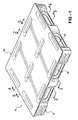
- FIG. 1 is a perspective view of the invention pallet
- FIGS. 2, 3 , 4 and 5 are cross-sectional views taken respectively on lines 2 - 2 , 3 - 3 , 4 - 4 and 5 - 5 of FIG. 1 ;
- FIG. 6 is a bottom perspective view of the pallet
- FIG. 7 is a top view of the pallet
- FIG. 8 is a side view of the pallet
- FIG. 9 is an end view of the pallet
- FIG. 10 is an exploded view of the pallet
- FIG. 11, 12 , 13 , 14 and 15 are fragmentary views showing details of reinforcing beam members
- FIG. 16 is a view of reinforcing rod members
- FIG. 17 is a fragmentary bottom view of the pallet
- FIG. 18 is a detail view taken within the circle 18 of FIG. 17 ;
- FIG. 19 is a detail view looking in the direction of the arrow 19 in FIG. 18 ;
- FIG. 20 is a fragmentary perspective view of the pallet structure seen in FIG. 18 .
- the invention pallet is formed of lower and upper plastic sheets 12 and 14 , knitted or fused together, four reinforcing steel beam members 16 encapsulated between the upper and lower sheets, and four metal rods 18 encapsulated in the underface of the pallet.
- Sheets 12 and 14 may be separately molded in a vacuum thermoforming process, may be formed of an organic polymeric material such as polyethylene, and may be knitted or fused together to form the pallet in a compression molding process.
- the molds for vacuum forming the sheets are not shown but may be constructed in accordance with known vacuum thermoforming techniques.
- Each of the upper and lower sheets is formed from a generally rectangular planar plastic sheet and the sheets are fused together utilizing the molds while the sheets are in a heated moldable state so that fusion may occur between the upper and lower sheets at any point where an interface is defined between the upper and lower sheets.
- Lower sheet 12 starts out as a generally rectangular sheet of polyethylene plastic material and is vacuum thermoformed in known manner utilizing a suitable lower mold.
- Lower sheet 12 includes upstanding end walls 12 a , upstanding sidewalls 12 b , a continuously upwardly opening peripheral groove 12 c extending around the perimeter of the sheet, a central upwardly opening groove 12 d for connecting the portion of the peripheral groove 12 c proximate one end wall 12 a with the portion of the peripheral groove 12 c proximate the opposite end wall 12 a , and top wall portions 12 e extending between side edge portions of the groove 12 c and the central groove 12 d .
- Central groove 12 d includes enlarged end portions 12 f , an enlarged central portion 12 g , and narrow portions 12 h extending between portions 12 f and 12 g.
- Lower sheet 12 further includes a plurality of upwardly extending hollow spacer knobs 12 i provided on the upper face of each top wall portion 12 e .
- the knobs are provided in laterally spaced rows along the entire length and width of the top walls 12 e .
- Knobs 12 i have a circular truncated cone configuration except that the confronting faces 12 j of the outboard knob rows extending lengthwise and widthwise of the sheet are flatted to define longitudinal channels 20 for seating and locating the respective beam members 16 . It will be seen that a channel 20 is provided along each outboard lengthwise edge of the sheet to accommodate a longitudinally extending beam 16 and further channels 20 are provided along each outboard end edge to accommodate a transversely extending beam 16 .
- channels 20 along the outboard end edges to accommodate transverse beam 16 are each interrupted by an enlarged end portion 12 f of the groove 12 d .
- a row of downwardly opening upwardly extending locator knobs 12 k are also provided in each top wall 12 e between the rows of flatted outboard spacer knobs. Locator knobs 12 k are staggered with respect to, and smaller than, spacer knobs 12 i.
- the underface 12 m of continuous groove 12 c will be seen to define a continuous rectangular perimeter footprint surface for the pallet and a downwardly opening channel 12 n is formed along each side of the rectangular footprint surface.
- Each channel 12 n includes a straight central main body portion 12 p extending parallel to a respective side edge of the footprint surface and cranked or angled end portions 12 q opening in the respective side edge of the footprint surface proximate a respective corner of the footprint surface.
- Upper sheet 14 starts out as a generally rectangular sheet of polyethylene plastic material and is vacuum thermoformed in known manner utilizing a suitable upper mold.
- Upper sheet 14 includes a generally planar top wall 14 a , forming the platform structure for the resulting pallet, a plurality of circumferentially spaced upwardly opening “U” shaped protrusions 14 b extending downwardly from the top wall, and a plurality of central “U” shaped protrusions 14 c extending downwardly from the top wall.
- Protrusions 14 b and 14 c are sized to fit nestingly and snugly within peripheral groove 12 c and central groove 12 d respectively with two spaced protrusions 14 b positioned along each side edge of the peripheral groove, two protrusions 14 b positioned in each end portion of the peripheral groove, and two protrusions 14 c positioned in the narrow portions 12 h of central groove 12 d.
- each beam 16 in cross section, include sidewalls 16 a , a top wall 16 b including a central “V” 16 c , and spaced bottom wall sections 16 d terminating in lips 16 e defining a central slot 16 f .
- Beam members 16 include two end transverse beam members having a length generally corresponding to the channel structure 20 defined at each end of the lower sheet and a pair of longitudinally beam members 16 each having a length generally corresponding to the length of the channel structures 20 provided along the side edges of the lower sheet. As best seen in FIGS. 14 and 15 , each end 16 g of each beam member has a 45° bevel configuration.
- Each rod 18 is sized to fit in a respective channel 12 n and includes a straight main body portion 18 a sized to fit in a respective channel main body portion 12 p and cranked end portions 18 b sized to fit in respective channel end portions 12 q.
- beam members 16 are positioned in the respective channel structures 20 .
- the parameters of the various parts are chosen such that with the lower sheet in a heated condition, beam members 16 when placed in end to end relation within the channel structures 20 are spaced apart at their beveled ends by a distance “X” as best seen in FIG. 14 .
- the molds are brought together in known fashion to compression press the upper sheet to the lower sheet to form the twin sheet pallet 10 with the beam member encapsulated between the upper and lower sheets and specifically with each beam member totally surrounded by upper sheet top wall 14 a , a lower sheet top wall 12 e and knob flats 12 j .
- the plastic material of the sheets fuses or knits together in known manner at all areas where the upper and lower sheets form an interface.
- the periphery 14 d of the top wall 14 a of the upper sheet is fused to the peripheral upper edge 12 r of the lower sheets; the side walls 14 e of each side protrusion 14 b are fused to the inboard face of an indentation 12 s in a side wall 12 b or an end wall 12 a of the lower sheet and an inboard wall 12 t of the lower sheet; the bottom walls 14 f of the protrusions 14 b are fused to bottom walls 12 u of the lower sheet groove 12 ; the side walls 14 e of the central protrusions 14 d are fused to side walls 12 v of the lower sheet; the bottom wall 14 f of each central protrusion 14 d is fused to a respective portion of the central bottom wall 12 w of the lower sheet; and the upper end of each hollow spacer knob 12 i fuses to the underface 14 g of the top wall 14 a of the upper sheet.
- the protrusions 14 b are sized such that the outboard wall 14 e of each protrusion 14 b actually seats against the inboard face of a respective indentation 12 s so that a space 22 is formed between the upper and lower sheets above and along the extent of each indentation 12 s .
- the knobs 12 i serve to define a space 24 between the upper and lower sheets in the pallet areas between the side grooves and the central groove. Spaces 22 and 24 will be seen to define a twin sheet or double wall configuration for the pallet to provide structural rigidity for the pallet.
- the plastic material of the pallet shrinks significantly so that the pallet itself undergoes shrinkage both end to end and side to side to bring the spaced apart beveled ends 16 g of the beam members together to form a continuous rectangular frame configuration within the pallet.
- this methodology whereby the beam members are not initially joined together to form a rigid frame structure but rather are placed individually within the channel structures with their beveled end in spaced relation, avoids the problem of having the knobs defining the channel structures pull away from the beam members as the plastic material of the pallet shrinks during the cooling process while the beam members maintain their initial rigid fixed positions within the upper and lower sheets with the result that the beam members in the final, cooled pallet, are loosely positioned within the upper and lower sheets rather than being firmly encapsulated in the channel structures according to the invention methodology.
- a cutting or routing step is performed to form a pair of slots 26 in the sidewalls of the pallet and extending laterally across the pallet to allow the entry of the forks of a forklift truck.
- an oblong cut out 28 is formed in each indentation 12 s of a sidewall 12 b , in the outboard sidewall 14 e and the inboard sidewall 14 e of the nested protrusion 14 b , in an inboard wall 12 t , in an inboard wall 12 b , in central protrusion side walls 14 e , in an inboard wall 12 v , in an inboard wall 12 t , and the inboard and outboard sidewalls 14 e of the nested protrusions 14 b , and in the indentation 12 s of the other sidewall 12 b .
- Similar cutouts 28 are formed in the end walls of the pallet to define further slots 26 .
- planar top wall 14 a of the upper sheet defines a generally planar platform surface for receipt of a pallet load and the bottom walls of the peripheral groove in the lower sheet and the central groove in the lower sheet coact to define a pallet footprint including a continuous rectangular perimeter footprint joined by a central footprint of the central groove.
- the rods 18 are positioned in the respective channels 12 n , with the main body rod portions positioned in the main body channel portions and the cranked rod end portions positioned in the channel cranked end portions, whereafter plastic material 30 is positioned over each rod, in a plastic fusion welding operation, to encapsulate the rods in the lower face of the pallet.
- the plastic fusion material 30 also fills channel end portions 12 x outboard of the ends of the rod crank ends so as to further encapsulate the rods.
- the plastic fusion material is flush with the underface of the pallet so as to hide the rods but not interfere with the ready movement of the pallet over transfer surfaces and transfer devices.
- the bottom of the finished plastic pallet cannot stretch under edge racking tension beyond what the stretch rods will allow.
- the upper steel beams and the lower steel rods are held efficiently in shear by the plastic structure creating a combined plastic/steel truss much stiffer than the individual components would be if they were not locked together.
- the invention pallet is also extremely simple in construction and therefore relatively inexpensive to produce and yet is extremely sturdy so as to provide an extremely long useful life.
- the invention construction also lends itself to simple and effective cleaning operations between pallet usages.
Abstract
A plastic twin sheet pallet and a method of forming the pallet. The pallet includes an upper plastic sheet and a lower plastic sheet selectively fused together to form a generally rectangular pallet having an upper platform structure. The pallet further includes a metallic support structure positioned beneath the platform structure between the upper and lower sheets and including a plurality of beam members arranged end to end in a rectangular frame configuration with each beam member generally parallel to and spaced inboard from the respective outer edge of the pallet. The pallet further includes a peripheral groove structure opening upwardly in the platform structure between each beam member and the respective outer edge of the pallet. The pallet defines a peripheral groove structure opening upwardly in the platform structure between each beam member and their respective outer edge of the pallet. With the lower sheet in a heated state the beam members are positioned in upwardly opening channels defined in the lower sheet with beveled ends of the beam members positioned end to end but in spaced relation, whereafter a thermoformed upper sheet is fused to the lower sheet to encapsulate the beam members between the sheets. As the resulting pallet cools and shrinks the end to end and side to side shrinkage of the pallet brings the beveled ends of the beam members together to form a continuous rectangular frame configuration firmly imbedded within the pallet. The pallet further includes reinforcing rods embedded in rectangular configuration in the lower footprint face of the pallet to augment the reinforcing action of the beam members.
Description
- This invention relates to shipping and storage pallets and more particularly to plastic pallets embodying a twin sheet construction.
- Whereas twin sheet plastic pallets have in general proven to be superior to the wooden pallets previously in use, prior art twin sheet pallets have tended to creep or sag after extended-periods of use especially when utilized in a racked manner with opposite edges of the pallet supported by spaced bars of a rack structure.
- This invention is directed to the provision of an improved twin sheet pallet.
- More specifically, this invention is directed to the provision of a twin sheet plastic pallet which is resistant to creeping or sag even after extended periods of usage in a racked environment.
- Yet more specifically, this invention is directed to the provision of a twin sheet plastic pallet that is rackable in both directions, either side to side or end to end.
- The invention pallet is of the plastic twin sheet type comprising an upper plastic sheet and a lower plastic sheet selectibly fused together to form a generally rectangular pallet having an upper platform structure.
- According to an important feature of the invention, the pallet further includes a metallic support structure positioned beneath the platform structure between the upper and lower sheets and including a plurality of beam members arranged end to end in a rectangular frame configuration with each beam member generally parallel to a respective outer edge of the pallet.
- According to a further feature of the invention, each beam member is spaced inboard with respect to the respective outer edge.
- According to a further feature of the invention, the pallet defines a groove structure opening upwardly in the platform structure between each beam member and the respective outer edge.
- According to a further feature of the invention, each groove structure is formed by portions of the upper sheet fused to portions of the lower sheet and the portions of the lower sheet forming the groove structures comprise a continuous upwardly opening peripheral groove extending around the perimeter of the lower sheet with bottom walls of the continuous groove forming a continuous rectangular perimeter footprint for the pallet.
- According to a further feature of the invention, the upper sheet defines a top wall forming the platform structure and a plurality of circumferentially spaced upwardly opening protrusions extending downwardly from the top wall and nesting within the continuous groove in the lower sheet to form the groove structures.
- According to a further feature of the invention, the pallet further includes a plurality of spacer knobs protruding from one of the sheets and fused to the other sheet and serving to space portions of the upper sheet from portions of the lower sheet; at least certain of the spacer knobs are arranged in rows; and the beam members are positioned between adjacent rows of the spacer knobs.
- According to a further feature of the invention, the spacer knobs are provided in and extend upwardly from the lower sheet and are fused to an underface of the upper sheet.
- According to a further feature of the invention, the pallet further includes upstanding locator knobs positioned between adjacent rows of spacer knobs and engaging an underface of a respective beam member.
- According to a further feature of the invention, the pallet further defines a central groove structure opening upwardly in the platform structure and extending between the peripheral groove structure proximate one side edge of the pallet and the peripheral groove structure proximate the opposite side edge of the pallet.
- According to a further feature of the invention, the pallet further includes aligned slots in side walls of the peripheral groove structures and in side walls of the central groove structure to allow passage of the forks of a forklift truck.
- The invention twin sheet pallet, according to a further aspect of the invention, comprises an upper generally rectangular sheet and a lower generally rectangular sheet selectively fused together to form a generally rectangular pallet having an upper platform structure; the lower sheet is formed with a continuous peripheral upwardly opening groove and a central upwardly opening groove extending from the peripheral groove proximate one side edge of the lower sheet to the peripheral groove proximate an opposite side edge of the sheet; and the upper sheet defines a top wall forming the platform structure and a plurality of circumferentially spaced upwardly opening protrusions, extending downwardly from the top wall and fusedly nested in the continuous peripheral groove in the lower sheet to form a continuous double walled thickness peripheral groove structure, and a plurality of central upwardly opening protrusions extending downwardly from the top wall and fusedly nested in the central groove in the lower sheet to form a double walled thickness central groove structure.
- According to a further feature of the invention, the underface of the pallet is configured to define a rectangular perimeter footprint surface and a metal rod is positioned proximate the footprint surface along each side edge of the rectangular footprint surface.
- According to a further feature of the invention, each rod is positioned in a downwardly opening channel provided in the footprint surface.
- According to a further feature of the invention, each rod is encapsulated by the lower sheet of the pallet by fused plastic material plugging the channel opening following positioning of the rod in the channel.
- According to a further feature of the invention, each rod includes a substantially straight main body portion and cranked end portions and the rods are arranged in end to end relation with the cranked end portion of one rod positioned proximate but unconnected to the cranked end portion of an adjacent rod.
- According to a further feature of the invention, each cranked end portion extends outwardly toward the respective side edge of the footprint surface.
- The invention also provides a method of forming a generally rectangular reinforced twin sheet plastic pallet comprising first and second plastic sheets selectively fused together with metallic beam members encapsulated therebetween.
- The invention methodology comprises thermoforming the first sheet to include four elongated channel structures arranged in end to end relation; with the first sheet in a heated state, placing a beam member in each channel structure in end to end relation and with the adjacent beam ends spaced apart; thermoforming the second sheet and fusing it to the first sheet to encapsulate the beam members in the channel structures; and allowing the fused together sheets to cool to allow the pallet to shrink both end to end and side to side to bring the spaced adjacent ends of the beam members together to form a continuous rectangular frame configuration.
- According to a further feature of the invention methodology, the beam members have beveled ends which are brought together in response to pallet shrinkage to font a bevel joint between each set of adjacent beam members.
- According to a further feature of the invention methodology, the lower sheet of the pallet is configured so that an underface of the lower sheet defines a continuous rectangular footprint surface for the pallet and a metallic rod is positioned proximate the footprint surface along each side edge of the footprint surface.
- According to a further feature of the invention methodology, each rod is positioned in a downwardly opening channel provided in the footprint surface.
- According to a further feature of the invention methodology, following positioning of each rod in the respective channel, plastic material is fused into the opening of the channel to encapsulate the rod within the lower plastic sheet.
- According to a further feature of the invention methodology, each rod includes a substantially straight main body portion and cranked end portions and the rods are arranged in end to end relation proximate the footprint surface with the cranked end portion of one rod positioned proximate but unconnected to the cranked end portion of an adjacent rod.
- According to a further feature of the invention methodology, each cranked end portion extends outwardly toward the respective side edge of the footprint surface.
- Other applications of the present invention will become apparent to those skilled in the art when the following description of the best mode contemplated for practicing the invention is read in conjunction with the accompanying drawings.
- The description herein makes reference to the accompanying drawings wherein like reference numerals refer to like parts throughout the several views, and wherein:
-
FIG. 1 is a perspective view of the invention pallet; -
FIGS. 2, 3 , 4 and 5 are cross-sectional views taken respectively on lines 2-2, 3-3, 4-4 and 5-5 ofFIG. 1 ; -
FIG. 6 is a bottom perspective view of the pallet; -
FIG. 7 is a top view of the pallet; -
FIG. 8 is a side view of the pallet; -
FIG. 9 is an end view of the pallet; -
FIG. 10 is an exploded view of the pallet; -
FIG. 11, 12 , 13, 14 and 15 are fragmentary views showing details of reinforcing beam members; -
FIG. 16 is a view of reinforcing rod members; -
FIG. 17 is a fragmentary bottom view of the pallet; -
FIG. 18 is a detail view taken within thecircle 18 ofFIG. 17 ; -
FIG. 19 is a detail view looking in the direction of thearrow 19 inFIG. 18 ; and -
FIG. 20 is a fragmentary perspective view of the pallet structure seen inFIG. 18 . - In overview, the invention pallet is formed of lower and upper
plastic sheets steel beam members 16 encapsulated between the upper and lower sheets, and fourmetal rods 18 encapsulated in the underface of the pallet.Sheets - Each of the upper and lower sheets is formed from a generally rectangular planar plastic sheet and the sheets are fused together utilizing the molds while the sheets are in a heated moldable state so that fusion may occur between the upper and lower sheets at any point where an interface is defined between the upper and lower sheets.
-
Lower sheet 12 starts out as a generally rectangular sheet of polyethylene plastic material and is vacuum thermoformed in known manner utilizing a suitable lower mold.Lower sheet 12 includesupstanding end walls 12 a,upstanding sidewalls 12 b, a continuously upwardly openingperipheral groove 12 c extending around the perimeter of the sheet, a central upwardly openinggroove 12 d for connecting the portion of theperipheral groove 12 c proximate oneend wall 12 a with the portion of theperipheral groove 12 c proximate theopposite end wall 12 a, andtop wall portions 12 e extending between side edge portions of thegroove 12 c and thecentral groove 12 d.Central groove 12 d includes enlargedend portions 12 f, an enlargedcentral portion 12 g, andnarrow portions 12 h extending betweenportions -
Lower sheet 12 further includes a plurality of upwardly extendinghollow spacer knobs 12 i provided on the upper face of eachtop wall portion 12 e. The knobs are provided in laterally spaced rows along the entire length and width of thetop walls 12 e.Knobs 12 i have a circular truncated cone configuration except that the confrontingfaces 12 j of the outboard knob rows extending lengthwise and widthwise of the sheet are flatted to definelongitudinal channels 20 for seating and locating therespective beam members 16. It will be seen that achannel 20 is provided along each outboard lengthwise edge of the sheet to accommodate a longitudinally extendingbeam 16 andfurther channels 20 are provided along each outboard end edge to accommodate a transversely extendingbeam 16. Note that thechannels 20 along the outboard end edges to accommodatetransverse beam 16 are each interrupted by an enlargedend portion 12 f of thegroove 12 d. A row of downwardly opening upwardly extendinglocator knobs 12 k are also provided in eachtop wall 12 e between the rows of flatted outboard spacer knobs.Locator knobs 12 k are staggered with respect to, and smaller than,spacer knobs 12 i. - The
underface 12 m ofcontinuous groove 12 c will be seen to define a continuous rectangular perimeter footprint surface for the pallet and a downwardly openingchannel 12 n is formed along each side of the rectangular footprint surface. Eachchannel 12 n includes a straight centralmain body portion 12 p extending parallel to a respective side edge of the footprint surface and cranked orangled end portions 12 q opening in the respective side edge of the footprint surface proximate a respective corner of the footprint surface. -
Upper sheet 14 starts out as a generally rectangular sheet of polyethylene plastic material and is vacuum thermoformed in known manner utilizing a suitable upper mold.Upper sheet 14 includes a generally planartop wall 14 a, forming the platform structure for the resulting pallet, a plurality of circumferentially spaced upwardly opening “U” shapedprotrusions 14 b extending downwardly from the top wall, and a plurality of central “U” shapedprotrusions 14 c extending downwardly from the top wall.Protrusions peripheral groove 12 c andcentral groove 12 d respectively with two spacedprotrusions 14 b positioned along each side edge of the peripheral groove, twoprotrusions 14 b positioned in each end portion of the peripheral groove, and twoprotrusions 14 c positioned in thenarrow portions 12 h ofcentral groove 12 d. - As best seen in
FIG. 11, 12 and 13, eachbeam 16, in cross section, include sidewalls 16 a, atop wall 16 b including a central “V” 16 c, and spacedbottom wall sections 16 d terminating inlips 16 e defining acentral slot 16 f.Beam members 16 include two end transverse beam members having a length generally corresponding to thechannel structure 20 defined at each end of the lower sheet and a pair oflongitudinally beam members 16 each having a length generally corresponding to the length of thechannel structures 20 provided along the side edges of the lower sheet. As best seen inFIGS. 14 and 15 , each end 16 g of each beam member has a 45° bevel configuration. - Each
rod 18 is sized to fit in arespective channel 12 n and includes a straightmain body portion 18 a sized to fit in a respective channelmain body portion 12 p and crankedend portions 18 b sized to fit in respectivechannel end portions 12 q. - Following the vacuum forming operations to form the upper and lower sheets, and with the upper and lower sheets still in a heated moldable state,
beam members 16 are positioned in therespective channel structures 20. The parameters of the various parts are chosen such that with the lower sheet in a heated condition,beam members 16 when placed in end to end relation within thechannel structures 20 are spaced apart at their beveled ends by a distance “X” as best seen inFIG. 14 . - Following the positioning of the beam members within the
channel structures 20 of the lower sheet with the beveled ends 16 g of adjacent beam members in spaced disposition, the molds are brought together in known fashion to compression press the upper sheet to the lower sheet to form thetwin sheet pallet 10 with the beam member encapsulated between the upper and lower sheets and specifically with each beam member totally surrounded by upper sheettop wall 14 a, a lowersheet top wall 12 e andknob flats 12 j. As the upper and lower sheets, in a heated moldable state, are brought together the plastic material of the sheets fuses or knits together in known manner at all areas where the upper and lower sheets form an interface. Specifically, theperiphery 14 d of thetop wall 14 a of the upper sheet is fused to the peripheralupper edge 12 r of the lower sheets; theside walls 14 e of eachside protrusion 14 b are fused to the inboard face of anindentation 12 s in aside wall 12 b or anend wall 12 a of the lower sheet and aninboard wall 12 t of the lower sheet; thebottom walls 14 f of theprotrusions 14 b are fused tobottom walls 12 u of thelower sheet groove 12; theside walls 14 e of thecentral protrusions 14 d are fused toside walls 12 v of the lower sheet; thebottom wall 14 f of eachcentral protrusion 14 d is fused to a respective portion of thecentral bottom wall 12 w of the lower sheet; and the upper end of eachhollow spacer knob 12 i fuses to the underface 14 g of thetop wall 14 a of the upper sheet. - As noted, the
protrusions 14 b are sized such that theoutboard wall 14 e of eachprotrusion 14 b actually seats against the inboard face of arespective indentation 12 s so that aspace 22 is formed between the upper and lower sheets above and along the extent of eachindentation 12 s. Further, theknobs 12 i serve to define aspace 24 between the upper and lower sheets in the pallet areas between the side grooves and the central groove.Spaces - According to the invention methodology, as the pallet cools following the fusing together of the upper and lower sheets, the plastic material of the pallet shrinks significantly so that the pallet itself undergoes shrinkage both end to end and side to side to bring the spaced apart beveled ends 16 g of the beam members together to form a continuous rectangular frame configuration within the pallet. Note that this methodology, whereby the beam members are not initially joined together to form a rigid frame structure but rather are placed individually within the channel structures with their beveled end in spaced relation, avoids the problem of having the knobs defining the channel structures pull away from the beam members as the plastic material of the pallet shrinks during the cooling process while the beam members maintain their initial rigid fixed positions within the upper and lower sheets with the result that the beam members in the final, cooled pallet, are loosely positioned within the upper and lower sheets rather than being firmly encapsulated in the channel structures according to the invention methodology.
- Following the fusing together of the upper and lower sheets to form the pallet and after allowing the material of the pallet to cool, a cutting or routing step is performed to form a pair of
slots 26 in the sidewalls of the pallet and extending laterally across the pallet to allow the entry of the forks of a forklift truck. Specifically, an oblong cut out 28 is formed in eachindentation 12 s of asidewall 12 b, in theoutboard sidewall 14 e and theinboard sidewall 14 e of the nestedprotrusion 14 b, in aninboard wall 12 t, in aninboard wall 12 b, in centralprotrusion side walls 14 e, in aninboard wall 12 v, in aninboard wall 12 t, and the inboard andoutboard sidewalls 14 e of the nestedprotrusions 14 b, and in theindentation 12 s of theother sidewall 12 b.Similar cutouts 28 are formed in the end walls of the pallet to definefurther slots 26. Theslots 26 in the various walls of the pallet coact to facilitate the handling of the pallet by a forklift truck approaching the pallet from either direction. In the completed pallet the planartop wall 14 a of the upper sheet defines a generally planar platform surface for receipt of a pallet load and the bottom walls of the peripheral groove in the lower sheet and the central groove in the lower sheet coact to define a pallet footprint including a continuous rectangular perimeter footprint joined by a central footprint of the central groove. - Also following the cooling of the pallet, the
rods 18 are positioned in therespective channels 12 n, with the main body rod portions positioned in the main body channel portions and the cranked rod end portions positioned in the channel cranked end portions, whereafterplastic material 30 is positioned over each rod, in a plastic fusion welding operation, to encapsulate the rods in the lower face of the pallet. Theplastic fusion material 30 also fillschannel end portions 12 x outboard of the ends of the rod crank ends so as to further encapsulate the rods. In the finished pallet, the plastic fusion material is flush with the underface of the pallet so as to hide the rods but not interfere with the ready movement of the pallet over transfer surfaces and transfer devices. - The invention pallet will be seen to provide many important advantages. Specifically, the encapsulated rectangular frame construction provides excellent rackability of the pallet in both directions, that is, whether racked end to end or side to side. Further, the invention construction provides a continuous longitudinally extending footprint along the underface of the pallet so that the pallet can pass easily over barriers and irregular transfer surfaces and transfer devices such for example as conveyors. Further the invention construction provides firm entrapment for the forks of the forklift truck so that the pallet even if unevenly loaded will not tend to tip off of the forks of the pallet as the pallet is lifted and transported by the fork. Further, the reinforcing rods augment the reinforcing action of the reinforcing beams and further contribute to the rackability of the pallet in both directions. Specifically, because the rod ends are cranked and the spaces around the rod ends are filled in with plastic weld, the bottom of the finished plastic pallet cannot stretch under edge racking tension beyond what the stretch rods will allow. In effect, the upper steel beams and the lower steel rods are held efficiently in shear by the plastic structure creating a combined plastic/steel truss much stiffer than the individual components would be if they were not locked together. The invention pallet is also extremely simple in construction and therefore relatively inexpensive to produce and yet is extremely sturdy so as to provide an extremely long useful life. The invention construction also lends itself to simple and effective cleaning operations between pallet usages.
- While the invention has been described in connection with what is presently considered to be the most practical and preferred embodiment, it is to be understood that the invention is not to be limited to the disclosed embodiments but, on the contrary, is intended to cover various modifications and equivalent arrangements included within the spirit and scope of the appended claims, which scope is to be accorded the broadest interpretation so as to encompass all such modifications and equivalent structures as is permitted under the law.
Claims (44)
1. A twin sheet plastic pallet including an upper plastic sheet and a lower plastic sheet selectively fused together to form a generally rectangular pallet having an upper platform structure, characterized in that:
the pallet further includes a metallic support structure positioned beneath the platform structure between the upper and lower sheets and including a plurality of beam members arranged end to end in a rectangular frame configuration with each beam member generally parallel to a respective outer edge of the pallet.
2. A pallet according to claim 1 wherein each beam member is spaced inboard with respect to the respective outer edge of the pallet.
3. A pallet according to claim 2 wherein the pallet defines a peripheral groove structure opening upwardly in the platform structure between each beam member and the respective outer edge of the pallet.
4. A pallet according to claim 3 wherein:
each groove structure is formed by portions of the upper sheet fused to portions of the lower sheet;
the portions of the lower sheet forming the groove structures comprise a continuous upwardly opening groove extending around the perimeter of the lower sheet with bottom walls of the continuous groove forming a continuous rectangular perimeter footprint surface of the pallet.
5. A pallet according to claim 4 wherein the pallet further includes a metal rod structure positioned proximate the footprint surface along each side edge of the footprint surface.
6. A pallet according to claim 5 wherein the metal rod structure comprises a metal rod positioned along each side edge in a downwardly opening channel provided in the footprint surface.
7. A pallet according to claim 6 wherein each rod is encapsulated by the lower sheet by fused plastic material plugging the channel opening following positioning of the rod in the channel.
8. A pallet according to claim 5 wherein each rod includes a substantially straight main body portion and cranked end portions and the rods are arranged in end to end relation with the cranked end portion of one rod positioned proximate but unconnected to the cranked end portion of an adjacent rod.
9. A pallet according to claim 8 wherein each cranked end portion extends outwardly toward the respective side edge of the footprint surface.
10. A pallet according to claim 4 wherein the upper sheet defines a top wall forming the platform structure and a plurality of circumferentially spaced upwardly opening protrusions extending downwardly from the top wall and nesting within the continuous groove in the lower sheet to form the groove structures.
11. A pallet according to claim 3 wherein:
the pallet further includes a plurality of spacer knobs protruding from one of the sheets and fused to the other sheet and serving to space portions of the upper sheet from portions of the lower sheet;
at least certain of the spacer knobs are arranged in rows; and
the beam members are positioned between adjacent rows of spacer knobs.
12. A pallet according to claim 11 wherein the spacer knobs are provided in and extend upwardly from the lower sheet and are fused to an underface of the upper sheet.
13. A pallet according to claim 12 wherein the pallet further includes upstanding locator knobs positioned between adjacent rows of spacer knobs and engaging an underface of a respective beam member.
14. A pallet according to claim 3 wherein:
the pallet further defines a central groove structure opening upwardly in the platform structure and extending between the peripheral groove structure proximate one side edge of the pallet and the peripheral groove structure proximate an opposite side edge of the pallet.
15. A pallet according to claim 14 wherein:
each groove structure is formed by portions of the upper sheet fused to portions of the lower sheet; and
the portions of the lower sheet forming the groove structures comprise a continuous upwardly opening perimeter groove extending around the perimeter of the lower sheet and a central upwardly opening groove extending between the perimeter groove structure proximate one side edge of the pallet and the perimeter groove structure proximate an opposite side edge of the pallet.
16. A pallet according to claim 15 wherein:
the upper sheet defines a top wall defining the platform structure and a plurality of upwardly opening protrusions extending downwardly from the top wall and nesting in the continuous perimeter groove and in the central groove to form the groove structures.
17. A pallet according to claim 16 wherein the pallet further includes aligned slots in side walls of the peripheral groove structures and in sidewalls of the central groove structure to allow passage of the forks of a forklift truck.
18. A pallet according to claim 17 wherein the pallet further includes a plurality of spacer knobs protruding from one of the sheets and fused to the other sheet and serving to spaced portions of the upper sheet from portions of the lower sheet.
19. A pallet according to claim 18 wherein at least certain of the spacer knobs are arranged in rows; and
the beam members are positioned between adjacent rows of spacer knobs.
20. A twin sheet plastic pallet including an upper generally rectangular sheet and a lower generally rectangular sheet selectively fused together to form a generally rectangular pallet having an upper platform structure, characterized in that:
the lower sheet is formed with a continuous peripheral upwardly opening groove and a central upwardly opening groove extending from the peripheral groove proximate one side edge of the lower sheet to the peripheral groove proximate an opposite side edge of the lower sheet; and
the upper sheet defines a top wall forming the platform structure and a plurality of circumferentially spaced upwardly opening protrusions extending downwardly from the top wall and fusedly nested in the continuous peripheral groove in the lower sheet, to form a continuous double wall thickness peripheral groove structure, and a plurality of central upwardly opening protrusions fusedly nested in the central groove in the lower sheet to form a double walled thickness central groove structure.
21. A pallet according to claim 20 wherein the pallet further includes aligned slots in sidewalls of the peripheral groove structure and in side walls of the central groove structure to allow passage of the forks of a forklift truck.
22. A pallet according to claim 21 wherein the pallet further includes a plurality of spacer knobs protruding from one of the sheets and fused to the other sheet and serving to space portions of the upper sheet between the groove structures from portions of the lower sheet between the groove structures.
23. A pallet according to claim 22 wherein:
the spacer knobs immediately inboard of the peripheral groove structure are arranged in parallel adjacent rows; and
metallic beam members are positioned between the adjacent parallel rows.
24. A method of forming a generally rectangular reinforced twin sheet plastic pallet comprising first and second plastic sheets selectively fused together with metallic beam members encapsulated therebetween, the method comprising:
thermoforming the first sheet to include four (4) elongated channel structures arranged in end to end relation;
with the first sheet in a heated state, placing a beam member in each channel structure in end to end relation and with the adjacent ends of the beam members spaced apart;
thermoforming the second sheet and fusing it to the first sheet to encapsulate the beam members in the groove structures; and
allowing the fused together sheets to cool to allow the pallet to shrink both end to end and side to side to bring the spaced apart ends of the beams together to form a continuous rectangular frame configuration.
25. A method according to claim 24 wherein:
the beam members have beveled ends which are brought together in response to pallet shrinkage to form a beveled joint between each set of adjacent beam members.
26. A method according to claim 25 wherein:
the channel structures are defined by parallel rows of spacer knobs protruding from the first sheet and fused to the second sheet and serving to space portions of the first sheet from portions of the second sheet and to define the depth of the channel structures.
27. A method according to claim 26 wherein:
the first sheet is a lower pallet sheet and the second sheet is an upper pallet sheet; and
the knobs project upwardly from the lower sheet and are fused to an underface of the upper sheet.
28. A method according to claim 24 wherein the first sheet is a lower plastic sheet and the second sheet is an upper plastic sheet and wherein the method includes the further step of configuring an underface of the lower sheet to define a continuous rectangular perimeter footprint surface for the pallet and positioning a metal rod structure proximate the footprint surface along each side edge of the rectangular footprint surface.
29. A method according to claim 28 wherein the metal rod structure comprises a metal rod positioned along each side edge in a downwardly opening channel provided in the footprint surface.
30. A method according to claim 29 wherein:
following positioning of each rod in the respective channel, plastic material is fused into the opening of the channel to encapsulate the rod within the lower plastic sheet.
31. A method according to claim 30 wherein each rod includes a substantially straight main body portion and cranked end portions and the rods are arranged in end to end relation proximate the footprint surface with the cranked end portion of one rod positioned proximate but unconnected to the cranked end portion of an adjacent rod.
32. A method according to claim 31 wherein each cranked end portion extends outward toward the respective side edge of the footprint surface.
33. A twin sheet plastic pallet including an upper plastic sheet and a lower plastic sheet selectively fused together to form a generally rectangular pallet having an upper platform structure, characterized in that:
an underface of the lower sheet defines a continuous rectangular perimeter footprint surface for the pallet; and
a metal rod is positioned proximate the footprint surface along each side edge of the rectangular footprint surface.
34. A pallet according to claim 33 wherein each rod is positioned in a downwardly opening channel provided in the footprint surface.
35. A pallet according to claim 34 wherein each rod is encapsulated by the lower sheet by fused plastic material plugging the channel opening following positioning of the rod in the channel.
36. A pallet according to claim 33 wherein:
each rod includes a substantially straight main body portion and cranked end portions; and
the rods are arranged in end to end relation with the cranked end portion of one rod positioned proximate but unconnected to the cranked end portion of an adjacent rod.
37. A pallet according to claim 36 wherein each cranked end portion extends outwardly toward the respective side edge of the footprint surface.
38. A pallet according to claim 33 wherein the pallet further includes a metallic support structure positioned beneath the platform structure between the upper and lower sheets and including a plurality of beam members arranged end to end in a rectangular frame configuration with each beam member generally proximate to a respective outer edge of the pallet in overlying relation to a respective rod.
39. A method of forming a twin sheet plastic pallet including an upper plastic sheet and a lower plastic sheet selectively fused together to form the pallet, the method comprising:
configuring the lower sheet so that an underface of the lower sheet defines a continuous rectangular footprint surface for the pallet; and
positioning a metal rod structure proximate the footprint surface along each side edge of the rectangular footprint surface.
40. A method according to claim 39 wherein the metal rod structure comprises a metal rod positioned along each side edge in a downwardly opening channel opening in the footprint surface.
41. A method according to claim 40 wherein following positioning of each rod in the respective channel plastic material is fused into the opening of the channel to encapsulate the rod within the lower plastic sheet.
42. A method according to claim 40 wherein:
each rod includes a substantially straight main body portion and cranked end portions; and
the rods are arranged in end to end relation proximate the footprint surface with the cranked end portion of one rod positioned proximate but unconnected to the cranked end portion of an adjacent rod.
43. A method according to claim 42 wherein each cranked end portion extends outwardly toward the respective side edge of the footprint surface.
44. A method according to claim 39 wherein the method includes the further step of providing a metallic support structure positioned beneath the platform structure beneath the upper and lower sheets and including a plurality of beam members arranged end to end in a rectangular frame configuration with each beam member generally proximate to a respective outer edge of the pallet in overlying relation to a respective rod.
Priority Applications (5)
| Application Number | Priority Date | Filing Date | Title |
|---|---|---|---|
| US11/333,170 US7343865B2 (en) | 2006-01-17 | 2006-01-17 | Rackable twin sheet pallet |
| PCT/US2006/049409 WO2007087065A2 (en) | 2006-01-17 | 2006-12-28 | Rackable twin sheet pallet |
| AT06846081T ATE551271T1 (en) | 2006-01-17 | 2006-12-28 | STACKABLE DOUBLE SHEET PALLET |
| EP06846081A EP1973788B1 (en) | 2006-01-17 | 2006-12-28 | Rackable twin sheet pallet |
| NO20083351A NO339118B1 (en) | 2006-01-17 | 2008-07-30 | Standable two-layer pallet |
Applications Claiming Priority (1)
| Application Number | Priority Date | Filing Date | Title |
|---|---|---|---|
| US11/333,170 US7343865B2 (en) | 2006-01-17 | 2006-01-17 | Rackable twin sheet pallet |
Publications (2)
| Publication Number | Publication Date |
|---|---|
| US20070163473A1 true US20070163473A1 (en) | 2007-07-19 |
| US7343865B2 US7343865B2 (en) | 2008-03-18 |
Family
ID=38261937
Family Applications (1)
| Application Number | Title | Priority Date | Filing Date |
|---|---|---|---|
| US11/333,170 Active 2026-05-20 US7343865B2 (en) | 2006-01-17 | 2006-01-17 | Rackable twin sheet pallet |
Country Status (5)
| Country | Link |
|---|---|
| US (1) | US7343865B2 (en) |
| EP (1) | EP1973788B1 (en) |
| AT (1) | ATE551271T1 (en) |
| NO (1) | NO339118B1 (en) |
| WO (1) | WO2007087065A2 (en) |
Cited By (18)
| Publication number | Priority date | Publication date | Assignee | Title |
|---|---|---|---|---|
| US20080141912A1 (en) * | 2006-12-19 | 2008-06-19 | Valentinsson Anders L | Transport pallet |
| US20090188412A1 (en) * | 2008-01-29 | 2009-07-30 | Georg Utz Holding Ag | Pallet |
| US20110110742A1 (en) * | 2008-04-14 | 2011-05-12 | Shuert Technologies, Llc | Frame stacking methods and spacers |
| EP2390198A1 (en) * | 2010-05-14 | 2011-11-30 | Philip John Fox Harris | Transport pallet |
| US20120037050A1 (en) * | 2009-02-18 | 2012-02-16 | B.B.P. Technologies Ltd. | non-flat deck-board pallet |
| EP2463208A1 (en) * | 2010-12-08 | 2012-06-13 | D.W. Plastics NV | Multipart pallet |
| US9242760B2 (en) | 2012-02-20 | 2016-01-26 | Roni Pal Israel 2000 Ltd. | Pallet and beams |
| CN106477216A (en) * | 2015-08-24 | 2017-03-08 | 德国邮政股份公司 | Device for automatically protection postal delivery thing |
| DE102015116056A1 (en) * | 2015-09-23 | 2017-03-23 | VD-Technology B.V. | Transport pallet for a transport container and method for its production |
| US20170166351A1 (en) * | 2015-12-15 | 2017-06-15 | Snyder Industries, Inc. | Pallet with integrated shift prevention features |
| USD799781S1 (en) * | 2016-03-31 | 2017-10-10 | PALLcon Services Company, Ltd. | Pallet with columns |
| CN108045698A (en) * | 2017-12-11 | 2018-05-18 | 成都市银隆新能源有限公司 | A kind of lithium battery transfer tray |
| US20190135485A1 (en) * | 2017-06-13 | 2019-05-09 | Rehrig Pacific Company | Fire retardant pallet assembly |
| WO2019145881A1 (en) * | 2018-01-23 | 2019-08-01 | Rdp (Nz) Limited | A shipping pallet and/or deck useful for such |
| USD869812S1 (en) | 2017-11-03 | 2019-12-10 | Inteplast Group Corporation | Pallet |
| US10882660B2 (en) * | 2018-05-31 | 2021-01-05 | Chep Technology Pty Limited | Repairable plastic pallet with carvings in the top deck and associated methods |
| US11027881B2 (en) * | 2018-07-31 | 2021-06-08 | Igps Logistics, Llc | Plastic pallet having an integrally formed deck and method of manufacturing the same |
| US11352169B2 (en) | 2019-01-18 | 2022-06-07 | Rehrig Pacific Company | Pallet assembly |
Families Citing this family (13)
| Publication number | Priority date | Publication date | Assignee | Title |
|---|---|---|---|---|
| US7611060B2 (en) | 2005-03-11 | 2009-11-03 | Hand Held Products, Inc. | System and method to automatically focus an image reader |
| US7780089B2 (en) | 2005-06-03 | 2010-08-24 | Hand Held Products, Inc. | Digital picture taking optical reader having hybrid monochrome and color image sensor array |
| US7568628B2 (en) | 2005-03-11 | 2009-08-04 | Hand Held Products, Inc. | Bar code reading device with global electronic shutter control |
| US7770799B2 (en) | 2005-06-03 | 2010-08-10 | Hand Held Products, Inc. | Optical reader having reduced specular reflection read failures |
| US7779764B2 (en) * | 2006-05-08 | 2010-08-24 | Chep Technology Pty Limited | Durable pallet and pallet block |
| US7624689B2 (en) * | 2006-09-01 | 2009-12-01 | Shuert Technologies, Inc. | One way plastic pallet |
| US20080116099A1 (en) * | 2006-11-22 | 2008-05-22 | Eduardo Garcia | Tray |
| US20100316291A1 (en) * | 2009-06-11 | 2010-12-16 | Shulan Deng | Imaging terminal having data compression |
| US8764033B2 (en) * | 2010-08-06 | 2014-07-01 | Robert Devine | Utility truck base reinforcement and method of manufacture |
| US8424469B2 (en) | 2011-03-09 | 2013-04-23 | Shuert Technology LLC | Plastic pallet with twin-sheet deck and runner structures |
| MX2013001828A (en) | 2012-02-14 | 2013-10-14 | Rehrig Pacific Co | Pallet assembly. |
| WO2017105531A1 (en) * | 2015-12-16 | 2017-06-22 | Airdex Corporation | Load bearing structure |
| CA2982035A1 (en) | 2016-10-11 | 2018-04-11 | Rehrig Pacific Company | Pallet with inset deck |
Citations (14)
| Publication number | Priority date | Publication date | Assignee | Title |
|---|---|---|---|---|
| US4606278A (en) * | 1984-09-28 | 1986-08-19 | Shuert Lyle H | Twin sheet pallet |
| US4742781A (en) * | 1984-12-03 | 1988-05-10 | Shuert Lyle H | Twin sheet pallet with sleeve retaining construction |
| US5042396A (en) * | 1988-07-29 | 1991-08-27 | Shuert Lyle H | Plastic pallet |
| US5117762A (en) * | 1990-02-26 | 1992-06-02 | Shuert Lyle H | Rackable plastic pallet |
| US5791262A (en) * | 1994-02-14 | 1998-08-11 | The Fabri-Form Co. | Reinforced plastic pallet |
| US5794544A (en) * | 1996-04-22 | 1998-08-18 | Shuert; Lyle H. | Plastic pallet |
| US6125770A (en) * | 1997-12-01 | 2000-10-03 | Paul Craemer Gmbh | Plastic pallet |
| US6199488B1 (en) * | 1997-10-07 | 2001-03-13 | James Favaron | Reinforced plastic pallets |
| US6357366B1 (en) * | 1999-02-05 | 2002-03-19 | Menasha Corporation | Rackable molded pallet |
| US6446563B1 (en) * | 1998-10-07 | 2002-09-10 | Harout Ohanesian | Thermoplastic pallet |
| US6718888B2 (en) * | 2000-04-11 | 2004-04-13 | Nextreme, Llc | Thermoformed platform |
| US6955129B2 (en) * | 2000-08-24 | 2005-10-18 | The Engineered Pallot Company, Llc | Plastic pallet design |
| US7086339B2 (en) * | 2003-04-29 | 2006-08-08 | Rehrig Pacific Company | Pallet assembly |
| US7165499B2 (en) * | 2003-02-04 | 2007-01-23 | Rehrig Pacific Company | Reinforced pallet |
Family Cites Families (4)
| Publication number | Priority date | Publication date | Assignee | Title |
|---|---|---|---|---|
| JPH05504923A (en) * | 1990-02-26 | 1993-07-29 | シャート ライル エイチ | Rackable plastic pallets |
| US5391251A (en) * | 1990-05-15 | 1995-02-21 | Shuert; Lyle H. | Method of forming a pallet |
| US5197396A (en) * | 1991-08-05 | 1993-03-30 | Penda Corporation | Double deck plastic pallet |
| US6955128B2 (en) * | 2001-10-19 | 2005-10-18 | Rehrig Pacific Company | Reinforced pallet |
-
2006
- 2006-01-17 US US11/333,170 patent/US7343865B2/en active Active
- 2006-12-28 AT AT06846081T patent/ATE551271T1/en active
- 2006-12-28 WO PCT/US2006/049409 patent/WO2007087065A2/en active Application Filing
- 2006-12-28 EP EP06846081A patent/EP1973788B1/en not_active Not-in-force
-
2008
- 2008-07-30 NO NO20083351A patent/NO339118B1/en unknown
Patent Citations (14)
| Publication number | Priority date | Publication date | Assignee | Title |
|---|---|---|---|---|
| US4606278A (en) * | 1984-09-28 | 1986-08-19 | Shuert Lyle H | Twin sheet pallet |
| US4742781A (en) * | 1984-12-03 | 1988-05-10 | Shuert Lyle H | Twin sheet pallet with sleeve retaining construction |
| US5042396A (en) * | 1988-07-29 | 1991-08-27 | Shuert Lyle H | Plastic pallet |
| US5117762A (en) * | 1990-02-26 | 1992-06-02 | Shuert Lyle H | Rackable plastic pallet |
| US5791262A (en) * | 1994-02-14 | 1998-08-11 | The Fabri-Form Co. | Reinforced plastic pallet |
| US5794544A (en) * | 1996-04-22 | 1998-08-18 | Shuert; Lyle H. | Plastic pallet |
| US6199488B1 (en) * | 1997-10-07 | 2001-03-13 | James Favaron | Reinforced plastic pallets |
| US6125770A (en) * | 1997-12-01 | 2000-10-03 | Paul Craemer Gmbh | Plastic pallet |
| US6446563B1 (en) * | 1998-10-07 | 2002-09-10 | Harout Ohanesian | Thermoplastic pallet |
| US6357366B1 (en) * | 1999-02-05 | 2002-03-19 | Menasha Corporation | Rackable molded pallet |
| US6718888B2 (en) * | 2000-04-11 | 2004-04-13 | Nextreme, Llc | Thermoformed platform |
| US6955129B2 (en) * | 2000-08-24 | 2005-10-18 | The Engineered Pallot Company, Llc | Plastic pallet design |
| US7165499B2 (en) * | 2003-02-04 | 2007-01-23 | Rehrig Pacific Company | Reinforced pallet |
| US7086339B2 (en) * | 2003-04-29 | 2006-08-08 | Rehrig Pacific Company | Pallet assembly |
Cited By (30)
| Publication number | Priority date | Publication date | Assignee | Title |
|---|---|---|---|---|
| US20080141912A1 (en) * | 2006-12-19 | 2008-06-19 | Valentinsson Anders L | Transport pallet |
| US8622006B2 (en) * | 2008-01-29 | 2014-01-07 | Georg Utz Holding Ag | Pallet |
| US20090188412A1 (en) * | 2008-01-29 | 2009-07-30 | Georg Utz Holding Ag | Pallet |
| US20110110742A1 (en) * | 2008-04-14 | 2011-05-12 | Shuert Technologies, Llc | Frame stacking methods and spacers |
| US8172495B2 (en) * | 2008-04-14 | 2012-05-08 | Shuert Lyle H | Frame stacking methods and spacers |
| US20120037050A1 (en) * | 2009-02-18 | 2012-02-16 | B.B.P. Technologies Ltd. | non-flat deck-board pallet |
| US8695512B2 (en) * | 2009-02-18 | 2014-04-15 | B.B.P. Technologies Ltd. | Non-flat deck-board pallet |
| US8857634B2 (en) | 2010-05-14 | 2014-10-14 | Philip John Fox Harris | Transport pallet |
| EP2390198A1 (en) * | 2010-05-14 | 2011-11-30 | Philip John Fox Harris | Transport pallet |
| EP2463208A1 (en) * | 2010-12-08 | 2012-06-13 | D.W. Plastics NV | Multipart pallet |
| US9242760B2 (en) | 2012-02-20 | 2016-01-26 | Roni Pal Israel 2000 Ltd. | Pallet and beams |
| CN106477216A (en) * | 2015-08-24 | 2017-03-08 | 德国邮政股份公司 | Device for automatically protection postal delivery thing |
| DE102015116056A1 (en) * | 2015-09-23 | 2017-03-23 | VD-Technology B.V. | Transport pallet for a transport container and method for its production |
| US20170166351A1 (en) * | 2015-12-15 | 2017-06-15 | Snyder Industries, Inc. | Pallet with integrated shift prevention features |
| USD799781S1 (en) * | 2016-03-31 | 2017-10-10 | PALLcon Services Company, Ltd. | Pallet with columns |
| USD899725S1 (en) * | 2016-03-31 | 2020-10-20 | PALLcon Services Company, Ltd. | Pallet with columns |
| USD816939S1 (en) | 2016-03-31 | 2018-05-01 | PALLcon Services Company, Ltd. | Pallet with columns |
| US20190135485A1 (en) * | 2017-06-13 | 2019-05-09 | Rehrig Pacific Company | Fire retardant pallet assembly |
| US10532852B2 (en) * | 2017-06-13 | 2020-01-14 | Rehrig Pacific Company | Fire retardant pallet assembly |
| USD927118S1 (en) | 2017-11-03 | 2021-08-03 | Inteplast Group Corporation | Pallet |
| USD869812S1 (en) | 2017-11-03 | 2019-12-10 | Inteplast Group Corporation | Pallet |
| CN108045698A (en) * | 2017-12-11 | 2018-05-18 | 成都市银隆新能源有限公司 | A kind of lithium battery transfer tray |
| CN111629972A (en) * | 2018-01-23 | 2020-09-04 | Rdp集团有限公司 | Shipping pallet and/or pallet for shipping pallet |
| WO2019145881A1 (en) * | 2018-01-23 | 2019-08-01 | Rdp (Nz) Limited | A shipping pallet and/or deck useful for such |
| US11273953B2 (en) | 2018-01-23 | 2022-03-15 | Rdp Group Limited | Shipping pallet and/or deck useful for such |
| US10882660B2 (en) * | 2018-05-31 | 2021-01-05 | Chep Technology Pty Limited | Repairable plastic pallet with carvings in the top deck and associated methods |
| US11305913B2 (en) | 2018-05-31 | 2022-04-19 | Chep Technology Pty Limited | Repairable plastic pallet with carvings in the top deck and associated methods |
| US11787598B2 (en) | 2018-05-31 | 2023-10-17 | Chep Technology Pty Limited | Repairable plastic pallet with removable support blocks and associated methods |
| US11027881B2 (en) * | 2018-07-31 | 2021-06-08 | Igps Logistics, Llc | Plastic pallet having an integrally formed deck and method of manufacturing the same |
| US11352169B2 (en) | 2019-01-18 | 2022-06-07 | Rehrig Pacific Company | Pallet assembly |
Also Published As
| Publication number | Publication date |
|---|---|
| WO2007087065B1 (en) | 2008-11-20 |
| EP1973788A2 (en) | 2008-10-01 |
| WO2007087065A3 (en) | 2008-10-02 |
| ATE551271T1 (en) | 2012-04-15 |
| NO339118B1 (en) | 2016-11-14 |
| EP1973788B1 (en) | 2012-03-28 |
| EP1973788A4 (en) | 2010-11-17 |
| NO20083351L (en) | 2008-07-30 |
| WO2007087065A2 (en) | 2007-08-02 |
| US7343865B2 (en) | 2008-03-18 |
Similar Documents
| Publication | Publication Date | Title |
|---|---|---|
| US7343865B2 (en) | Rackable twin sheet pallet | |
| US7726248B2 (en) | Twin sheet pallet | |
| US4879956A (en) | Plastic pallet | |
| AU2008232611B2 (en) | Plastic pallet with sleeved reinforcing rods and associated method for making the same | |
| US8291839B2 (en) | Pallet with alignment features | |
| US5596933A (en) | Reinforced plastic pallet | |
| US6644219B2 (en) | Pallet assembly | |
| US6668735B2 (en) | Pallet with a plastic platform | |
| US6962115B2 (en) | Blow molded pallet with pre-formed inserts | |
| NZ299185A (en) | Thermoformed pallet comprises plastics structure formed from twin-sheet thermoplastics sheeting and having a load supporting deck and feet | |
| US8943981B2 (en) | Reinforced plastic pallet | |
| US20090000527A1 (en) | Three piece welded plastic pallet | |
| EP2467304B1 (en) | Transport pallet | |
| US10077133B2 (en) | Nestable pallets and methods for forming the same | |
| JP4539215B2 (en) | Plastic pallet | |
| KR20170039086A (en) | Pallet and method of making a pallet | |
| US7624689B2 (en) | One way plastic pallet | |
| US6959650B2 (en) | Conveyorable plastic thermoformed pallet and method for making pallet | |
| EP4056600A1 (en) | Pallet and method for manufacturing same | |
| JP2005206195A (en) | Synthetic resin pallet |
Legal Events
| Date | Code | Title | Description |
|---|---|---|---|
| STCF | Information on status: patent grant |
Free format text: PATENTED CASE |
|
| FPAY | Fee payment |
Year of fee payment: 4 |
|
| FPAY | Fee payment |
Year of fee payment: 8 |
|
| MAFP | Maintenance fee payment |
Free format text: PAYMENT OF MAINTENANCE FEE, 12TH YR, SMALL ENTITY (ORIGINAL EVENT CODE: M2553); ENTITY STATUS OF PATENT OWNER: SMALL ENTITY Year of fee payment: 12 |