US20070150480A1 - Service delivery platform - Google Patents
Service delivery platform Download PDFInfo
- Publication number
- US20070150480A1 US20070150480A1 US11/400,249 US40024906A US2007150480A1 US 20070150480 A1 US20070150480 A1 US 20070150480A1 US 40024906 A US40024906 A US 40024906A US 2007150480 A1 US2007150480 A1 US 2007150480A1
- Authority
- US
- United States
- Prior art keywords
- service
- sdp
- services
- entity
- management
- Prior art date
- Legal status (The legal status is an assumption and is not a legal conclusion. Google has not performed a legal analysis and makes no representation as to the accuracy of the status listed.)
- Abandoned
Links
- 238000012384 transportation and delivery Methods 0.000 title claims abstract description 83
- 238000007726 management method Methods 0.000 claims abstract description 440
- 238000000034 method Methods 0.000 claims abstract description 189
- 230000008569 process Effects 0.000 claims description 131
- 230000010354 integration Effects 0.000 claims description 84
- 238000013499 data model Methods 0.000 claims description 70
- 230000003993 interaction Effects 0.000 claims description 35
- 238000004891 communication Methods 0.000 claims description 18
- 230000004044 response Effects 0.000 claims description 12
- 230000004048 modification Effects 0.000 claims description 7
- 238000012986 modification Methods 0.000 claims description 7
- 238000013501 data transformation Methods 0.000 claims description 5
- 238000013507 mapping Methods 0.000 claims description 4
- 238000006243 chemical reaction Methods 0.000 claims description 3
- 239000000470 constituent Substances 0.000 claims description 2
- 238000002716 delivery method Methods 0.000 claims 1
- 238000011161 development Methods 0.000 abstract description 27
- 239000000047 product Substances 0.000 description 137
- 230000006870 function Effects 0.000 description 74
- 230000008520 organization Effects 0.000 description 46
- 230000018109 developmental process Effects 0.000 description 30
- 238000010586 diagram Methods 0.000 description 26
- 238000001994 activation Methods 0.000 description 17
- 238000012544 monitoring process Methods 0.000 description 17
- 230000004913 activation Effects 0.000 description 16
- 230000008859 change Effects 0.000 description 16
- 238000005516 engineering process Methods 0.000 description 14
- 238000010200 validation analysis Methods 0.000 description 13
- 230000007246 mechanism Effects 0.000 description 12
- 238000012545 processing Methods 0.000 description 12
- 230000009471 action Effects 0.000 description 11
- 238000013475 authorization Methods 0.000 description 10
- 238000012552 review Methods 0.000 description 10
- 230000009466 transformation Effects 0.000 description 9
- 101150042248 Mgmt gene Proteins 0.000 description 8
- 238000013459 approach Methods 0.000 description 8
- 239000003795 chemical substances by application Substances 0.000 description 8
- 230000000694 effects Effects 0.000 description 8
- 238000000926 separation method Methods 0.000 description 8
- 238000013461 design Methods 0.000 description 7
- 230000032258 transport Effects 0.000 description 5
- 230000000007 visual effect Effects 0.000 description 5
- 230000008901 benefit Effects 0.000 description 4
- 230000000977 initiatory effect Effects 0.000 description 4
- 238000005204 segregation Methods 0.000 description 4
- 230000001360 synchronised effect Effects 0.000 description 4
- 230000002776 aggregation Effects 0.000 description 3
- 238000004220 aggregation Methods 0.000 description 3
- 238000013506 data mapping Methods 0.000 description 3
- 238000000354 decomposition reaction Methods 0.000 description 3
- 238000009826 distribution Methods 0.000 description 3
- 230000036541 health Effects 0.000 description 3
- 238000012423 maintenance Methods 0.000 description 3
- 238000013468 resource allocation Methods 0.000 description 3
- 230000011664 signaling Effects 0.000 description 3
- 238000012550 audit Methods 0.000 description 2
- 230000005540 biological transmission Effects 0.000 description 2
- 230000001413 cellular effect Effects 0.000 description 2
- 239000012141 concentrate Substances 0.000 description 2
- 238000007596 consolidation process Methods 0.000 description 2
- 238000012937 correction Methods 0.000 description 2
- 230000006872 improvement Effects 0.000 description 2
- 238000005259 measurement Methods 0.000 description 2
- 238000004806 packaging method and process Methods 0.000 description 2
- 238000009877 rendering Methods 0.000 description 2
- 238000003860 storage Methods 0.000 description 2
- 238000000844 transformation Methods 0.000 description 2
- 230000007704 transition Effects 0.000 description 2
- KJLPSBMDOIVXSN-UHFFFAOYSA-N 4-[4-[2-[4-(3,4-dicarboxyphenoxy)phenyl]propan-2-yl]phenoxy]phthalic acid Chemical compound C=1C=C(OC=2C=C(C(C(O)=O)=CC=2)C(O)=O)C=CC=1C(C)(C)C(C=C1)=CC=C1OC1=CC=C(C(O)=O)C(C(O)=O)=C1 KJLPSBMDOIVXSN-UHFFFAOYSA-N 0.000 description 1
- 101001094649 Homo sapiens Popeye domain-containing protein 3 Proteins 0.000 description 1
- 101000608234 Homo sapiens Pyrin domain-containing protein 5 Proteins 0.000 description 1
- 101000578693 Homo sapiens Target of rapamycin complex subunit LST8 Proteins 0.000 description 1
- 241000257303 Hymenoptera Species 0.000 description 1
- 102100027802 Target of rapamycin complex subunit LST8 Human genes 0.000 description 1
- 230000006978 adaptation Effects 0.000 description 1
- 238000004458 analytical method Methods 0.000 description 1
- 238000010923 batch production Methods 0.000 description 1
- 238000012508 change request Methods 0.000 description 1
- 238000012790 confirmation Methods 0.000 description 1
- 238000013500 data storage Methods 0.000 description 1
- 230000009849 deactivation Effects 0.000 description 1
- 230000007547 defect Effects 0.000 description 1
- 230000018044 dehydration Effects 0.000 description 1
- 238000006297 dehydration reaction Methods 0.000 description 1
- 230000001934 delay Effects 0.000 description 1
- 230000001419 dependent effect Effects 0.000 description 1
- 238000001514 detection method Methods 0.000 description 1
- 239000000284 extract Substances 0.000 description 1
- 239000012467 final product Substances 0.000 description 1
- 230000036571 hydration Effects 0.000 description 1
- 238000006703 hydration reaction Methods 0.000 description 1
- 230000008676 import Effects 0.000 description 1
- 238000002955 isolation Methods 0.000 description 1
- 230000004807 localization Effects 0.000 description 1
- 238000004519 manufacturing process Methods 0.000 description 1
- 239000000463 material Substances 0.000 description 1
- 239000011159 matrix material Substances 0.000 description 1
- 230000005012 migration Effects 0.000 description 1
- 238000013508 migration Methods 0.000 description 1
- 230000006855 networking Effects 0.000 description 1
- 238000013439 planning Methods 0.000 description 1
- 238000009428 plumbing Methods 0.000 description 1
- 238000007781 pre-processing Methods 0.000 description 1
- 230000002265 prevention Effects 0.000 description 1
- 230000011218 segmentation Effects 0.000 description 1
- 238000004904 shortening Methods 0.000 description 1
- 238000000638 solvent extraction Methods 0.000 description 1
- 239000000725 suspension Substances 0.000 description 1
- 238000012360 testing method Methods 0.000 description 1
- 238000012546 transfer Methods 0.000 description 1
- 238000013519 translation Methods 0.000 description 1
- 230000001960 triggered effect Effects 0.000 description 1
- 238000013024 troubleshooting Methods 0.000 description 1
Images


Classifications
-
- H—ELECTRICITY
- H04—ELECTRIC COMMUNICATION TECHNIQUE
- H04M—TELEPHONIC COMMUNICATION
- H04M3/00—Automatic or semi-automatic exchanges
- H04M3/42—Systems providing special services or facilities to subscribers
- H04M3/42136—Administration or customisation of services
- H04M3/42153—Administration or customisation of services by subscriber
- H04M3/42161—Administration or customisation of services by subscriber via computer interface
-
- G—PHYSICS
- G06—COMPUTING; CALCULATING OR COUNTING
- G06Q—INFORMATION AND COMMUNICATION TECHNOLOGY [ICT] SPECIALLY ADAPTED FOR ADMINISTRATIVE, COMMERCIAL, FINANCIAL, MANAGERIAL OR SUPERVISORY PURPOSES; SYSTEMS OR METHODS SPECIALLY ADAPTED FOR ADMINISTRATIVE, COMMERCIAL, FINANCIAL, MANAGERIAL OR SUPERVISORY PURPOSES, NOT OTHERWISE PROVIDED FOR
- G06Q10/00—Administration; Management
- G06Q10/06—Resources, workflows, human or project management; Enterprise or organisation planning; Enterprise or organisation modelling
-
- G—PHYSICS
- G06—COMPUTING; CALCULATING OR COUNTING
- G06Q—INFORMATION AND COMMUNICATION TECHNOLOGY [ICT] SPECIALLY ADAPTED FOR ADMINISTRATIVE, COMMERCIAL, FINANCIAL, MANAGERIAL OR SUPERVISORY PURPOSES; SYSTEMS OR METHODS SPECIALLY ADAPTED FOR ADMINISTRATIVE, COMMERCIAL, FINANCIAL, MANAGERIAL OR SUPERVISORY PURPOSES, NOT OTHERWISE PROVIDED FOR
- G06Q30/00—Commerce
- G06Q30/02—Marketing; Price estimation or determination; Fundraising
-
- G—PHYSICS
- G06—COMPUTING; CALCULATING OR COUNTING
- G06Q—INFORMATION AND COMMUNICATION TECHNOLOGY [ICT] SPECIALLY ADAPTED FOR ADMINISTRATIVE, COMMERCIAL, FINANCIAL, MANAGERIAL OR SUPERVISORY PURPOSES; SYSTEMS OR METHODS SPECIALLY ADAPTED FOR ADMINISTRATIVE, COMMERCIAL, FINANCIAL, MANAGERIAL OR SUPERVISORY PURPOSES, NOT OTHERWISE PROVIDED FOR
- G06Q30/00—Commerce
- G06Q30/04—Billing or invoicing
-
- G06Q50/60—
-
- Y—GENERAL TAGGING OF NEW TECHNOLOGICAL DEVELOPMENTS; GENERAL TAGGING OF CROSS-SECTIONAL TECHNOLOGIES SPANNING OVER SEVERAL SECTIONS OF THE IPC; TECHNICAL SUBJECTS COVERED BY FORMER USPC CROSS-REFERENCE ART COLLECTIONS [XRACs] AND DIGESTS
- Y02—TECHNOLOGIES OR APPLICATIONS FOR MITIGATION OR ADAPTATION AGAINST CLIMATE CHANGE
- Y02P—CLIMATE CHANGE MITIGATION TECHNOLOGIES IN THE PRODUCTION OR PROCESSING OF GOODS
- Y02P90/00—Enabling technologies with a potential contribution to greenhouse gas [GHG] emissions mitigation
- Y02P90/80—Management or planning
Definitions
- the present application relates generally to provision of services such as telecommunication services. More particularly, the present application relates to a service delivery platform and method to improve the delivery of telecommunications services.
- Telecommunications service providers provide services to their customers in response to customer orders, change requests and other processes.
- One particular class of service providers is telecommunications service providers, which provide telecommunication services to their customers, referred to as subscribers.
- Telecommunications services currently include both wire line and wireless technologies.
- wire line telecommunication services include telephone service and related services such as voice mail, call forwarding, three way calling and caller identification, or cable television service and associated cable-provided services, such as internet access.
- wireless telecommunication services include cellular telephone service and associated services such as voice mail and three way calling, wireless electronic mail and paging.
- Provision of such services includes many aspects.
- the service must be initially provisioned, or established. This can include establishing an account for charging and billing the subscriber. This can include setting up service provision channels, such as designating a telephone number or other unique resource for the subscriber, providing dedicated hardware and software for the subscriber, such as installing a telephone line. After provisioning, if the service is provided on a per-unit basis, the service must be metered to measure the quantity of the service consumed. Bills must be generated and payments credited. If additional services are subscribed, the additional services must be provisioned and the account adjusted accordingly. Each change requires updating the equipment and software involved in service provision.
- SP Service Provider
- Legacy systems may be implemented using hardware and software which are fully functional but no longer supported or no longer the best choice. Such legacy systems may be technologically incompatible with new equipment for providing services which are to be packaged with a legacy service. New implementations of services or features are preferably built on advanced equipment and software to leverage current technologies, efficiencies and standardized tools. Getting legacy systems to work well with newly installed systems may be difficult to accomplish technically and may require substantial time and cost. As one example, many current telecommunications services are provided using the standardized Advanced Intelligent Network. Newer equipment makes use of the infrastructure of the internet, which employs a data transfer protocol such as transmission control protocol/internet protocol (TCP/IP). Even a technical interworking of new and legacy systems is possible, the resulting system may not include all desired functionality and may not be optimized for the service provider's needs. The final product or suite or products may be limited by the limitations of the incorporated legacy system.
- TCP/IP transmission control protocol/internet protocol
- the present embodiments provide a service delivery platform, including method and apparatus for managing the delivery of a variety of services to customers or subscribers.
- the service delivery platform (SDP) is a platform architecture that fully exploits the convergence opportunities made available for the service providers (SPs) recently.
- SPs service providers
- the SDP creates, hosts, and manages services over different channels and end user devices.
- the implementation of the SDP will dramatically simplify service deployment and management, and allow the enterprise to develop new services more rapidly with the reduced development efforts.
- FIG. 1 is a block diagram of a service provider system
- FIG. 2 is a functional block diagram of a service delivery system
- FIG. 3 is a functional block diagram of as service delivery platform for use in the service delivery system of FIG. 1 ;
- FIG. 4 is a physical architecture diagram of a service delivery platform
- FIG. 5 is an interaction diagram illustrating a process of changing features of an existing service using a service delivery platform
- FIG. 6 is an interaction diagram illustrating a process of creating a new offer using a service delivery platform
- FIG. 7 is an interaction diagram illustrating a process of creating a billing feed using a service delivery platform
- FIG. 8 is an interaction diagram illustrating a process of providing a value-added reseller with a customer view using a service delivery platform
- FIG. 9 is an interaction diagram illustrating a process of creating a new account in an enterprise environment using a service delivery platform
- FIG. 10 is an alternative interaction diagram illustrating a process of creating an account with two new services using a service delivery platform
- FIG. 11 is an interaction diagram illustrating a process of authenticating and authorizing an end user of services using a service delivery platform
- FIG. 12 is an interaction diagram illustrating a process of handling a provisioning exception when provisioning services using a service delivery platform
- FIG. 13 is an interaction diagram illustrating a process of changing offer properties of an offer of services by a service provider, using a service delivery platform
- FIG. 14 illustrates an object model for use in conjunction with a system and method like the present embodiments
- FIG. 15 illustrates exemplary implementations of the disclosed products and processes of the present invention.
- the present invention provides a technology architecture that enables efficient and rapid creation and support of applications by service providers who provide or seek to provide services to subscribers.
- the architecture standardizes the interfaces linking applications to operational and back office support systems and network capabilities. This reduces the time required for the service creation process and gets products to market faster. It also reduces the cost of service creation and support.
- the architecture provides a common, reusable set of development tools. It allows reuse of discrete and modular functionality across the entire platform. It has the capability to define and apply common control policies to applications. And it has the capabilities to define and manage integrated profiling of users, services and resources. These all provide greater flexibility in bundling and packaging features and applications to create new services.
- the present invention provides a service delivery platform which is modular, flexible and designed to support the delivery of value-added services.
- the service delivery platform includes a suite of plug-and-play solutions built on a standardized platform, such as the Microsoft .NET platform, available from Microsoft Corp., Redmond, Wash. This platform is optimized for delivery to SMBs as managed services.
- the service delivery platform further provides a modular, end-to-end service delivery platform that substantially automates sales, order management, provisioning, billing and operations management.
- the service delivery platform relies on a reusable, component-based model that maximizes reuse and flexible service bundling.
- the service delivery platform can be extended to the widest variety of services, service providers and customers.
- telecommunications services that can beneficially be implemented in accordance with the service delivery platform include hosted Microsoft Exchange messaging services, including mobile electronic mail (email), facsimile and short message service and email archiving; hosted Microsoft Sharepoint, which is a system allowing network-based collaboration within an organization and with customers and business partners; Unified Messaging/Unified Communications (UM/UC); HiPath Openscape, a multimodal communications application from Siemens Enterprise Networks, San Jose, Calif.; web hosting; media on demand; secure instant messaging; web conferencing and live meetings (LM); and Voice Over Internet Protocol (VoIP); Microsoft Customer Relationship Manager (CRM); Microsoft Great Plains, which provides capabilities for financial management, distribution, manufacturing, project accounting, human resource management, field service management, and business analytics; and television over Internet Protocol (IP TV), and others applications.
- This list is intended to be illustrative and not exhaustive.
- a system in accordance with the present embodiments reduces the amount of work required to implement new services by incorporating the functions common to all managed services into the service delivery platform itself. For example, for developing core service functionality, common routines such as logging, metering, tracking, etc., are well-defined and available for use by the service. For developing portal screens for the user interface (UI) for a service, pre-existing WebParts, from Microsoft Sharepoint, reduce the UI development time. For adding a new service description to a catalog of services, the service delivery platform provides a standardized service catalog structure which defines elements to be included, which ensures seamless integration with the rest of the service. Further, for creating provisioning logic and workflows, a rules engine based on Microsoft BizTalk simplifies the effort required to implement workflow.
- UI user interface
- Existing workflows provide a starting point for implementing new workflows.
- the system in accordance with the present embodiments isolates interface complexities from developers and allows reuse of existing interfaces.
- the system features an interface to a billing platform which is architected to minimize changes with additional services.
- existing reports can be used as a starting point.
- Well-defined data structures reduce development time.
- the system allows the additional service to suggest modifications to existing operations support processes, rather than establishing new processes.
- FIG. 1 is a block diagram of a service provider system 100 .
- the system 100 includes customer-side components 102 and system-side components 104 .
- the components communicate over an enterprise messaging backbone 106 .
- the customer-side components 102 include a customer self-service function 108 , a customer management system 110 , an order manager 112 , a usage manager 114 , and a customer database manager 116 .
- the customer side components 102 provide order entry, billing and customer care functionalities.
- the self-service function 108 allows a customer or service subscriber to view or modify an account without assistance and intervention by an agent of the service provider. This could be through World Wide Web access by the subscriber or by actuation of a telephone menu system.
- the order manager 112 manages the provisioning of new or changed services for subscribers.
- the usage manager 114 monitors usage of the service, for example, to ensure the customer only accesses services in accordance with his subscription.
- the customer database manager 116 manages the content of and access to the customer database. Other components may be included or substituted depending on the particular services provided or the particular service provider.
- the system-side components 104 include a network 120 , a third party supplier gateway 122 , a billing and invoicing system 124 , an enterprise manager 126 , external interfaces 128 , and a service delivery platform 130 .
- the network 120 includes the service delivery infrastructure of data processing equipment and associated software.
- the third party supplier gateway 122 is a portal permitting service providers other than the service provider associated with the system 100 to provide services to customers.
- the billing and invoicing system 124 receives information about the nature and amount of services used, terms of service between the service provider and the subscriber and generates a bill for the subscriber.
- the enterprise manager 126 provides overall system control.
- the external interfaces 128 allow the system 100 to communicate data and information with other sources.
- the service delivery platform 130 creates, hosts, manages, controls, and deploys the value-added services provided by the system 100 .
- the service delivery platform 130 operates as a system within the larger service provider system 100 .
- the service delivery platform 130 interacts with the entire system 100 through the enterprise messaging backbone 106 .
- the enterprise messaging backbone provides interfaces and process management over the entire network, bridging system and information in order to provide complete and consistent operations and management.
- the service delivery platform 130 will be described in greater detail below.
- FIG. 2 is a functional block diagram of a service delivery system 200 including the service delivery platform 130 of FIG. 1 .
- the service delivery system 200 includes the service delivery platform 130 , a service activation function 202 , a service integration and management function 204 , an operations support system 206 , business support systems 208 and service platforms 210 .
- the SDP 130 is a core engine that encapsulates support services for value added services that might be offered by the service provider.
- the SDP 130 includes service creation, service deployment, service enablement and service assurance capabilities as will be discussed below.
- the service activation function 202 permits initiation of service provision to one or more customers. It presents a user interface or other access portal to a customer of the service provider or an agent or operator working on behalf of the service provider to activate the service. This function 202 also allows subsequent modification of the service, such as adding or deleting capabilities. The customer may access this function 202 himself, such as over a World Wide Web interface or through a telephone menu system. Alternatively, the customer may engage the operator in a phone call or live online session, or by any other means, to specify the service requirements.
- the service integration and management (SIM) function 204 includes a customer relationship manager (CRM) front end 212 and a portal 214 .
- the SIM function 204 allows users, both internal users such as operators and customer relations managers and external users such as customers the ability to access and use SDP services.
- the CRM front end 212 provides the hardware and software for interacting with a customer or operator. Any suitable customer relations management device or service may be used. Examples include call center software and hardware which allows customers to speak by telephone with operators and allows the operators, in turn, to activate and update service provisioning using the service delivery platform 130 .
- the CRM front end 212 interacts with a CRM interface web service 216 to access data and other information of the SDP 130 .
- the SDP 130 has a counterpart CRM integration adapter 218 which communicates with the CRM interface web service 216 , preferably using internet protocol (IP) or other standard data communication.
- IP internet protocol
- the portal 214 allows outside users access to the SDP 130 and includes a portal interface web service 220 .
- the SDP 130 has a counterpart portal integration adapter 222 .
- the portal web service 220 and the portal integration adapter 222 preferably use internet protocol (IP) or another standard.
- IP internet protocol
- Customers may utilize external customer relation management (CRM) systems to request service activation. The customers will purchase product services or packages offered by service catalog for the external systems, not for the SDP.
- CRM customer relation management
- the portal 214 allows communication between the SDP 130 and these external systems.
- the operations support system (OSS) 206 provides inventory control, monitoring, etc., and is integrated with the SDP 130 .
- the OSS 206 includes an inventory/resources function 224 and a manager of managers (MOM) 226 .
- the OSS 206 permits integration between the SDP 130 and new or pre-existing OSS systems for the enterprise.
- the OSS 206 uses Microsoft's EAI middleware, BizTalk, to offer coded business events, a fundamental architecture backbone, workflow management, data requirements, and data transformation rules required to integrate the service provider's Customer Relationship Management, Billing, and Provisioning Services.
- the inventory/resources function 224 operates with an inventory/resources web service 228 which communicates with a counterpart inventory/resources adapter 230 of the SDP.
- the MOM 226 operates in conjunction with a MOM interface web service 232 which communicates with a counterpart MOM integration adapter 234 of the SDP 130 .
- the business support systems 208 provide billing, customer relation management functions, etc., and are integrated with the SDP 130 .
- the business support systems (BSS) 208 include a billing function 236 , an invoicing function 238 , a customer insight function 240 and a customer relation manager 242 .
- the BSS 208 receives billing records and other information about the provision of services to the customer by the service provider.
- Billable data records as created by a metering service are submitted to the back-end billing system 236 for billing and real-time charging purposes.
- Billing integration with BSS allows operators to effectively monetize their services to customers based on their service usage and to prevent revenue leaks due to missing service events.
- the billable data records submitted to the operator's business support systems are also be used by the invoicing function 238 , the customer insight function 240 and the customer relation manager 242 .
- the invoicing function 238 uses the billing data records and other user account information to prepare and send invoices to customers.
- the customer insight function 240 extracts information about customer behavior, purchasing patterns and so forth. For example, this function 240 enables service providers to analyze service usage activities of subscribers based on access history in order to generate abstract usage patterns and supply such valuable insight to value-added services for fine-tuning personalization engines.
- the customer relation manager 242 monitors controls the way in which interaction with a customer is tailored to each individual customer, based on other information about the customer, such as services purchased, payment patterns, etc.
- the billing function 236 interacts with the SDP 130 using a billing interface web service 244 .
- the SDP 130 has a counterpart billing integration adapter 246 .
- the invoicing function 238 interacts with the SDP 130 using an invoice interface web interface 248 , which communicates with an invoicing integration adapter 250 of the SDP 130 .
- the customer insight function 240 interacts with the SDP 130 using an insight interface web service 252 , which has a counterpart insight integration adapter 254 of the SDP 130 .
- the CRM 242 interacts with the SDP 130 using a CRM interface web service 256 , which in turn has a counterpart CRM integration adapter 258 .
- FIG. 3 is a functional block diagram of a Service Control/Order Management Component Architecture 300 for use in the service delivery system of FIG. 1 .
- the component architecture 300 is divided up in the four Service Control/Order Management Component modules that make up a larger infrastructure interoperating with the Enterprise Messaging Backbone.
- the Service Control/Order Management Component provides integrated subscriber and service management. It includes common logic that allows resources and services to be dynamically configured based on user profile, service definition, policy information, current resource allocation, and resource state.
- This environment shall also consist of the control services that provide identity management for access control, metering service for creating billable data records, profile and personalization management, notification engine to support push-based alerts to customers, and content provider services that facilitate the integration of SDP with content providers.
- modules include a Service Deployment Environment 302 , a Service Creation Environment 304 , a Service Enablement Environment 306 and a Service Assurance Environment 308 .
- the component architecture 300 includes a Service Interaction and Management Environment 310 .
- This environment 310 may be omitted from some embodiments of the SDP architecture. However, when included, it is tightly integrated to the SDP architecture.
- the environment 310 provides the interfaces through which users interact with services.
- the Service Deployment Environment 302 provides deployment tools and mechanisms and resource management to help system administrators to manage deployed services in a distributed network.
- This module provides resource management that helps system administrators to manage deployed services in a distributed network. As an example, it supports the integration with content distribution networks to distribute services to operators' edge networks on a global scale to enable customers to access services hosted by the nearest servers.
- the Service Creation Environment 304 consists of several subsidiary components that allow for the creation of new services to be introduced to the Service Control Environment. Further, the Service Creation (SC) Environment 304 provides a development environment for software developers to create new services and to extend existing ones. The Service Creation Environment 304 simplifies the creation and reduces the time-to-market of new services. This module further provides the service catalogue that manages the services, an integrated development environment, and platform software development kits (SDKs) to facilitate the creation of new services. It also helps content providers create new content applications that leverage the services from the SDP.
- SDKs platform software development kits
- the SC Environment 304 provides a development environment for software developers to create new services and to extend existing ones. It simplifies the creation and reduces the time-to-market of new services. Essentially, this environment creates necessary capabilities to host new services and deploy them to the SCM environment so that the customers can sign-up, configure and receive any information services that are hosted and managed by the SDP.
- the SC Environment 304 is comprised of the following modules. These modules create and port-in any necessary capabilities to deliver new or updated data services to the customers;
- IDE Integrated Development Environment
- development toolkit should be utilized to facilitate building of new features and services that utilize component oriented, service building blocks that to build new services.
- ACA.NET provides APIs to third party developers and includes deployment infrastructure.
- Service Configuration Tool facilitates building of Execution and Control and Management functions capabilities.
- a testing environment can be set up to check for any errors before the new services are launched to the SCM environment.
- ACA.NET is a set of application blocks that are generally built on the Microsoft.NET platform. ACA.NET complements and extends the .NET framework with common architecture and services. Additionally, the ACA.NET framework is built on the new development paradigm of Service Oriented Architecture (SOA). Additionally, ACA.NET is configurable based upon Aspect Oriented Architecture (AOA) which allows the behavior of an application to be configured via XML configuration files and attribute declarations instead of programmatically. ACA.NET is intended to abstract the infrastructure details of messaging between objects away from developers allowing the developers to concentrate on enabling functionality while ACA.NET generates the necessary plumbing.
- AOA Aspect Oriented Architecture
- ACA.NET is composed of a Service, Framework, and Aspect architectures.
- the Service architecture consists of the business logic and the communication infrastructure.
- the Service architecture enables messaging between objects via transports. Messages have a type and wire format specific to the system being built. Messages can be serialized and marshaled.
- the transports include web services, .NET Remoting, and in-process function calls.
- the Framework architecture consists of “mainline” core functionality such as data access and manipulation and “sideline” functionality such as caching and remoting.
- the Aspect architecture allows behavior declaration to instance objects that enable the Service and Framework architectures.
- ACA.NET developers can quickly create and enable applications that can be easily deployed on the SDP platform.
- ACA.NET also has wizards to transform existing classes and components into Web Services without writing any new code.
- There are no API calls into the framework so misuse of the framework and bugs are eliminated or reduced.
- services can be deployed over multiple transports without affecting service code.
- application logic is protected from changes in communication technologies.
- ACA.NET 3.0 allows developers to create loosely coupled applications that communicate to compose large, complex systems.
- ACA.NET automatically generates the code for the sender and the receiver and the underlying transports that are used to communicate messages with the service layer, which is the core functionality that is developed by the vendor. Using this model, vendors can rapidly develop applications that can be seamlessly deployed within the SDP environment.
- ACA.NET is based on Aspect Oriented architecture. Aspects are a declarative way to control the behavior of an application's functionality. Aspect attributes are set through XML configurations rather than programmatically through code. This reduces the amount of custom code and increases consistency throughout an application.
- An example of Aspect Oriented Architecture is Authorization. Virtually all applications must use some form of authorization, regardless of how it may be implemented. The basic functionality for authorization remains the same for all applications. Thus, using ACA.NET vendors can quickly configure global attributes for authorization then using minimal code can implement it as desired while certain core functionality remains centrally controlled.
- the Service Enablement Environment 306 provides support for the execution of SDP and value added services. This includes service control, service orchestration and management and service execution.
- the Service Enablement Environment 306 includes a Service Brokering and Integration Environment 312 , a Service Control module 314 and Service Execution module 316 .
- ACA.NET can also help vendors extend their applications into other areas of the SDP platform by enabling them to quickly and efficiently write to Microsoft Exchange Server, Microsoft Active Directory, or Microsoft Operations Manager (MOM).
- MOM Microsoft Operations Manager
- the ACA.NET Framework writes significant events to the event log, providing a way to debug the application during development and after deployment. It also helps administrators detect and diagnose problems when they occur.
- the critical events in ACA.NET are not only logged to the event log but also published as WMI events. The message in any of the event logs contains detailed information and is human readable. Each event ID is defined distinctly within each framework and therefore can be used as an event filter by monitoring tools such as MOM.
- ACA.NET reports significant events within the frameworks through the publishing of WMI events. These events cover all the events that the ACA.NET Framework writes to the NT event log.
- the mechanism by which Windows collects performance data on various system resources is called the performance counter. Performance counters can provide useful information on how the system is running. They not only provide statistics on how much stress a system or application is under, but also allow the application throughput measuring.
- ACA.NET takes advantage of performance counters to expose the inner health and stress of the framework to monitoring tools. Applications built with ACA.NET have critical performance counters built-in just by using the framework.
- the events generated by the ACA.NET framework (for example, a Data Service configuration failure) are written to the event log by default.
- ACA.NET Logging Service you need the configuration to use the EventLogSink, run the Log Distributor, and then call WriteToLog in your code to write to the event log.
- the ACA.NET Framework instrumentation event log uses the name of the framework that the event originated from as the event source of the logged message.
- ACA.NET operators can quickly enable existing applications as web services and extend them to use server other server and system components much more efficiently than would be possible without ACA.NET. Additionally any new development can be developed more quickly and with more consistency, allowing developers to concentrate on the core services rather than communications within the application or within an integrated system.
- the Service Brokering and Integration Environment 312 consists of service orchestration that provides rule-based process scheduling and integration services that integrate the service delivery platform with content management, BSS, OSS, and device management systems to provide end-to-end services to customers.
- the Service Control module 314 provides integrated profile and service management.
- the Service Control module 314 includes common logic that allows resources and services to be dynamically configured based on user profile, service definition, policy information, current resource allocation, and resource state. Accordingly, the Service Control module 314 includes an Identity Management and Administration function 318 , a Profile Management function 320 , a Service Catalog 322 , a Security Policy Management module 324 and a Reporting/Auditing function 326 .
- the Identity Management and Administration function 318 allows management and control of identity information for service subscribers. Operators need an identity management solution to prevent unauthorized access to their services and protect the privacy of customer data. By providing effective security management for identity data, the identity management system also helps to prevent the revenue leakage problem that results from identity theft and malicious attacks, which has plagued operators on a global scale.
- the Identity Management and Administration function 318 includes an Access Management function, a Confidentiality function, an Identity Integration function, a Unified Directory and provision for Single Sign-on.
- Identity Administration applies to identity lifecycle management; that is, the provisioning and maintenance of digital identities for customers and content providers.
- the Access Management function is the service associated with establishing, enforcing, and managing the authentication, authorization, and auditing policies for customers and content providers.
- the Confidentiality function applies to protecting the privacy of connections between customers and services and securing identity data managed by SDP against unauthorized access. Identity data is often distributed in multiple systems within an operator's environment, or across different Internet communities.
- the Identity Integration function represents a holistic approach to the management of distributed but interrelated identities in separate repositories by providing a consistent, accurate representation of identities across heterogeneous systems while recognizing the identity ownership roles of individual systems.
- the Unified Directory is a consolidated or federated database for managing subscriber, service, and device information.
- Single Sign-on is a mechanism to verify a user across multiple applications through a single authentication challenge.
- the Profile Management function 320 allows management of subscriber and other profiles. Information about subscribers, networks, and services are managed in profiles. A profile is a container of properties for a particular subject. Profile management function 320 manages the following profiles.
- This profile contains properties about the operator's CDN that the SDP deployment environment supports for deploying services onto servers on edge networks. It also contains profiles for network elements in the operator's network including SMS, MMS, HLS, and others.
- Each profile contains identity data about a subscriber, including the subscriber's registered account name and access credential, address, and other identity data. It also contains preferences, subscriptions, summarized usage patterns, and device configurations for the subscriber.
- Each profile contains the identity data about a content provider, which is used by the content provider service to manage the access to the operator's SDP system from content providers.
- Service Profile Each service deployed by the operator needs to be managed in profiles in order to facilitate operations management.
- the service profiles also facilitate access to each service from device applications.
- the Service Catalog 322 includes a business level set of service and products that are used to manage packages and offers that are sold/resold to customers and resellers.
- the Service Catalog in one embodiment is organized as follows:
- Product A Product is hardware or software used to provide a consumable unit of service. Each product is based on an application and/or hardware that enables services and service variants.
- Service A Service is an atomic derivative of a Product (i.e., the minimum possible) that offers a consumable unit of service.
- SDP can support one or many services.
- Service Variant is a catalog unit derived from Service that contains configured details and attributes that define a set of unit of service.
- the system supports creating different variants of every service, so that the service is offered to different types of target users.
- Offer An Offer is set of Service Variants for presentation to customers for purchase.
- Service offers consist of one or many Service Variants. It can also include other offers.
- Service Group A Service Group is a container used to allow customers to group end-users and link the accounts to a service template.
- a customer is a service provider and an end user is a service subscriber.
- Solution A solution is a set of service variants or offers that represents a customer's right for subscription. When a customer subscribes to an offer or service variant, that selection becomes a solution for that customer. The customer's end users or subscribers will be eligible to utilize the corresponding services that are included in the solution.
- the Service Catalog provides all the necessary information about value-added services that can be hosted on the Accenture's SDP. It is a reference data source that will describe the product and feature information, network location, configuration, and access mechanisms of each service. SDP supports two different ways in which the service activation request can be submitted to the SDP:
- the Service Catalog helps the customers who are requesting service activation or configuration directly from the SDP's portal by presenting all the selectable options and features for desired value-added service.
- the Service Catalog will be retrieved and configured into the SDP's portal so that the customers can “browse” through the catalog to select the products and features for the service activation.
- the catalog elements can be selected by the customers on the portal and submitted to the SDP as part of a service activation request order.
- the order management module is responsible for pre-preprocessing the service activation requests, and the Provision Engine picks up all the selected catalog items and provisions them as service products and features.
- the workflow manager may trigger billing events based on the catalog items selected by the customers to properly bill the customers for the products and features.
- the customers For the instances where the customers utilize external CRM systems to request service activation, the customers purchase product services or packages offered by the service catalog for the external systems, not for the SDP. Therefore, the external catalog only provides product and feature information for service activation.
- the SDP's service catalog then complements this by providing other technical information about the services such as service configuration, network resources, and access mechanisms to deliver the services that are being activated.
- the SDP's service catalog should be comprehensive to accommodate the service activation requests sent by external systems.
- the identity management solution for SDP provides four major functions:
- the Service Control module 314 further includes the Security Policy Management module 324 .
- the Security Policy Management module 324 provides a single authoritative, integrated and federation directory, provided via Active Directory and interoperating with an SDP Access Manager to ensure that capabilities and information with the platform are relevant and private.
- the Security Policy directory may be characterized by a Role and a Privilege.
- a Role is a business classification assigned to a customer or account that is defined by a set of characteristics or privileges. Usage of the Role in SDP allows for specialized distinction of abilities to represent a business function, such as a value added reseller (VAR) as a role, where the VAR role represents each of the abilities that a VAR or accounts of a VAR is able to perform.
- VAR value added reseller
- a Privilege is a business characteristic or right that is represented in SDP. An example of this may be the right to create an account or over-ride service pricing.
- the grouping of privileges defines the Role and within SDP, the usage of Role and Privilege is extremely flexible and is not defined via inline code. What this does is allow SDP to define new roles and new privileges as extended capabilities and new business agreements are formed.
- the Reporting/Auditing function 326 provides standardized logging functions to support reporting and audit functions. In one embodiment, this is characterized by the following:
- Activity/Availability SDP activity and availability reporting. This may include service uptime, transactions/sec, active users, time based activity, etc.
- QoS/GoS Quality of Service and Grade of Service reporting. This can include reporting over platform and over value added service (VAS).
- VAS over value added service
- VAS usage reporting including either VAS specific or platform general information.
- Platform specific reporting includes information such as subscription to service, most common used services and most common used features.
- SDP events and auditing logs This includes, for example, a number of failed login attempts, login history, suspension history, etc.
- Performance reporting on platform health. This includes metrics-based reporting on counters such as average provision time, number of expired processes, number of retry attempts, active accounts, etc.
- Resource Reporting over SDP physical and logical resources that cover each Service. This may include quota levels, resources exceeding critical level, resources over utilized, resource over time, etc.
- End-User End-User reporting, number of services, subscribed service health.
- Customer Customer reporting, number of services, number of accounts, service usage, resource usage, etc.
- reporting and reporting content may be included or substituted as well.
- the Service Execution module 316 forms a standardized framework and architecture to execute services for a subscriber or an application.
- the Service Execution module 316 encourages reuse of existing components such as a VXML media server.
- the Service Execution module 316 leverages a set of common services such as authentication, authorization, presence, and personal information management functions.
- the Service Execution Module 316 includes in one embodiment Service Gateways 328 , Service Building Blocks 330 and Infrastructure 332 .
- the Service Gateways 328 are responsible for managing solutions for customers and value-added resellers (VARs).
- a Solution is a container for the Service Variants and Offers selected by a Customer to be reserved for their Users.
- the first type is Third Party Service Access Gateways, which extend the service delivery platform to support third party retail and wholesale service providers such as content providers, gateway providers and retail channels.
- the second type is Network & Service Gateways which provide interfaces to network and service elements to allow higher layer service logic to access them in a standardized and protected way.
- the Service Building Blocks 330 provide a set of common services and resources that are generally common to all SDP value added services.
- the Service Building Blocks 330 provide synergy across products and simplify handling of special customer requests. Several exemplary building blocks are described below. Many others may be included as well.
- a Session/Signaling building block provides real-time management of a service session for data, voice, and video applications. This building block also signals the appropriate network and service elements to set up one or more sessions in order to deliver service. Further, the Session/Signaling building block maintains the session as required to support the service. Examples include a call agent using session initiation protocol (SIP), H.323 data communication protocol, Media Gateway Control Protocol, etc., SIP proxies, a Video on Demand (VoD) server, SS7 to PSTN and mobile networks, etc.
- SIP session initiation protocol
- H.323 data communication protocol H.323 data communication protocol
- Media Gateway Control Protocol etc.
- SIP proxies a Video on Demand (VoD) server
- SS7 to PSTN and mobile networks, etc.
- a Content Management building block provides content provisioning and management capabilities including Digital Rights Management (DRM). Further, this building block may be shared across services such as internet protocol television (IPTV), VoD) and it provides provisioning and management application programming interfaces (APIs). Also, the Content Management building block provides a mechanism for real-time interaction with content by working with security access authentication modules such as “authenticate user,” “check parental controls” and other access, providing uniform resource locators (URL) to a content delivery network (CDN) and correctly encoded content, and providing a DRM key to access content.
- security access authentication modules such as “authenticate user,” “check parental controls” and other access
- URL uniform resource locators
- CDN content delivery network
- a Notification Engine building block provides a high-performance platform for scalable notification services that generate messages customized to meet target subscribers' specific needs.
- the notification messages, or alerts can originate from a variety of sources such as external data feeds and data updates by value-added services, and they can be delivered to various devices including pocket PCs, PCs or mobile telephones through multiple communication channels.
- Typical notification messages include those for appointment reminders, flight delays, and availability of new service or content.
- the Notification Engine in one embodiment is an orchestrated process that supports event collection, event generation, event distribution and subscription.
- a Presence/Location building block provides common service for managing state and context information for users, applications, and devices, such as IP address, bit rate, network location, device, preferences, etc. Further, the Presence/Location building block keeps track of current user and service profiles including user preferences and subscribed service profiles. Also, the Presence/Location building block forms a centralized or federated repository for managing user and service profiles including features and parameters needed to execute services. Still further, the Presence/Location building block provides protocols and interfaces for accessing and updating presence/state information. Examples of such protocols include Session Initiation Protocol for Instant Messaging and Presence Leveraging Extensions (SIMPLE), Extensible Messaging and Presence Protocol (XMPP) and Java Message Service (JMS).
- SIMPLE Session Initiation Protocol for Instant Messaging and Presence Leveraging Extensions
- XMPP Extensible Messaging and Presence Protocol
- JMS Java Message Service
- Examples include a Class 5 Switch subscriber/service database, a Remote Authentication Dial In User Service (RADIUS) server, a Wireless Home Location Registrar (HLR) and the Third Generation Partnership Project IP Multimedia System (3GPP-IMS) Home Subscriber Server (HSS).
- RADIUS Remote Authentication Dial In User Service
- HLR Wireless Home Location Registrar
- 3GPP-IMS Third Generation Partnership Project IP Multimedia System
- a Security Services building block provides common authentication and authorization services that can be shared across applications and services platform.
- a Presentation/Rendering building block provides real-time data transformation and formatting to support different types of devices such as extensible markup language (XML), hypertext markup language (HTML), and wireless markup language (WML).
- XML extensible markup language
- HTML hypertext markup language
- WML wireless markup language
- the Presentation/Rendering building block also provides format conversion functions on behalf of servers and devices.
- a Metering Service building block acts as a mediation system between the service providers and billing systems.
- This building block is an orchestrated process that supports; event collection, aggregation, transformation, tracking and submission.
- This building block receives or captures events in call detailed record (CDR) format from other services for tracking and billing purposes.
- CDR call detailed record
- the building block further integrates with the operator's billing system by converting CDR data to billable data records and submitting them to the operator's billing system for real-time charging and billing purposes.
- the Metering Service building block supports multiple units of measurement by event type, volume (in bytes), time, locality, and content type, based on business requirements.
- the Metering Service building block supports the use of Internet Protocol Detailed Record (IPDR) as the standard data format for billable data records and supports Charging Control which allows integration with billing engines to support pre-paid environments such as real-time signaling networking and post-paid environments, and combinations.
- IPDR Internet Protocol Detailed Record
- the Metering engine receives or captures events in call detailed record (CDR) format from other services for tracking and billing purposes. It integrates with the operator's or service provider's billing system by converting CDR data to billable data records and submitting them to the operator's billing system for real-time charging and billing purposes. It supports multiple units of measurement by event type, volume (in bytes), time, locality, and content type, based on business requirements.
- CDR call detailed record
- the metering engine is an orchestrated process that involves the following tasks:
- IPDR Internet Protocol Detailed Record
- IPDR is a standard defined by IPDR.Org, an open consortium of leading service providers, equipment vendors, system integrators, and billing and mediation vendors collaborating to facilitate the exchange of usage and control data between network and hosting elements and business support systems. IPDR defines an XML-based schema to represent CDR details for billing purposes, and it is widely supported by many leading billing systems vendors.
- a Media Services building block provides media access and delivery services and provides a request/response mechanism for accessing multi-media such as audio, video and data. Further, the Media Services building block supports protocols for delivering media to devices, applications, and users, and provides media transformation capabilities and encoding and decoding services. Examples include a VoD server, CDN, Broadcast TV head-end, a Web server using HTTP/HTTPS, an audio server and a VoiceXML Media Server.
- a Media Gateways building block provides a translation function between media streams for different networks and clients. Examples include a voice over internet protocol (VoIP) to time division multiplexing (TDM) media gateway and other vocoding devices.
- VoIP voice over internet protocol
- TDM time division multiplexing
- a Bridging building block bridges media such as voice, video and data for multi-user collaboration.
- the building block preferably ideally supports reformatting to different devices such as Media Gateway functions. Examples include voice conference bridges, data conferencing such as the facilities provided by WebEx, PlaceWare and MeetingPlace, and video conferencing.
- a Naming/Routing building block provides a name resolution mechanism for identifying services and resources in networked environment. Further this building block provides routing service to determine the optimal path and allocates networked resources. Still further, this building block dynamically assigns resources to devices and servers.
- a Messaging building block provides various forms of messaging between addressable users, devices, and applications and provides protocols, routing, and data stores to deliver messages. Further, the building block provides channel and routing mechanisms to support notification services. Examples include electronic mail (SMTP, POP3, IMAP), instant messaging, voice mail, fax and short message service (SMS).
- SMTP electronic mail
- POP3, IMAP instant messaging
- voice mail voice mail
- fax short message service
- a Synchronization Services building block manages and synchronizes information between applications and servers that need to use similar information. Examples include a Personal Information Manager (PIM) calendar and contacts across devices, such as Microsoft ActiveSync.
- PIM Personal Information Manager
- the Infrastructure 332 of the Service Execution Module 316 allows for a set of Next Generation Network (NGN) services to facilitate support of emerging and future value added services.
- NTN Next Generation Network
- the Infrastructure 332 includes and is not limited to in an all-IP network approach to the support for Data, Voice, Wireless, Rich Media Content, and Unified Messaging Services.
- the Service Brokering and Integration Environment 312 provides support for the execution of Service Control/Order Management and value added services.
- This environment 312 includes Service Control, Service Orchestration and Management and Service Delivery.
- the environment 312 includes several modules, including a Process Management module 334 , an Order Management module 336 , a Provisioning Management module 338 , a Content Management module 340 , a Network Integration module 342 , a Device Integration module 344 , and a OSS/BSS Integration module 346 .
- the Service Brokering component in SDP is a set of core service control elements designed to control network resources and coordination of services.
- Resource control will allow fundamental control to the Service Execution infrastructure for management of ports, server connections, and other when customers access service resources.
- the service resources will work to monitor and control quality of service (QoS) to allow for efficient usage of service resources. This will involve reallocation, redirection and denial of services in order to maximize the availability of the service resources.
- QoS quality of service
- the Process Management module 334 coordinates information flow within SDP, acting as a message processing backbone. Further, the Process Management module 334 enables integration of all internal (enterprise application integration, or EAI) and external (business-to-business, or B2B) applications and services. The Process Management module 334 is further responsible for orchestrating and executing workflow. In one embodiment, it is implemented with Microsoft BizTalk Server 2004 , but other implementations are possible.
- the Order Management module 336 interacts with one provisioning system or trading partner at a time, accepting complex orders to be “decomposed” into more atomic “work orders” to be workable by provisioning entities. This module creates work orders based on decomposition criteria, dynamically releases work orders and validates work orders.
- the Provisioning Management module 338 receives, processes, and fulfils the provision requests for authorized users.
- the Provisioning Management module 338 in one embodiment consists of capabilities for service provision management and directory provision management.
- the Content Management module 340 implements an offer syndication process that includes the acquisition, aggregation, transformation, staging, rating, and publishing of a variety of content from content providers and aggregators.
- the Network Integration module 342 leverages the network service elements, such as those for MMS, SMS, ILS, SIP, and so on, to provide end-to-end solutions for customers.
- the Network Integration 342 leverages the network service elements, such as those for MMS, SMS, HLS, SIP, and so on, to provide end-to-end solutions for customers.
- the Content Integration 344 operates to simplify integration tasks, connect through an adapter to retrieve content and provide the content to the value-added services which provision them to customers' devices.
- the Device Integration module 346 provides device management and device adaptation for value-added services. This includes fault management, or the process of identifying and fixing device-related system or application problems and faults and configuration, or providing device configurations. The also includes accounting, or managing profiles and service usage of all devices, and performance, or identifying network congestion or system performance issues and providing fixes, and security, including ensuring access to specific services.
- the OSS/BSS Integration module 348 provides a common framework for integration with OSS, including device services; BSS, including billing system; and network service elements, including LBS, SIP, SMS/MMS, and HLS.
- the Service Creation Environment 304 is a development environment for software developers to create new services and to extend existing ones.
- the Service Creation Environment 304 simplifies the creation and reduces the time-to-market of new services.
- the Service Creation Environment 304 includes a Service Directory 350 , an IDE and .NET Framework 352 , a Service Configurator 354 , Software Development Kits (SDKs) 356 , and user interface (UI) Widgets and Wizards 358 .
- SDKs Software Development Kits
- UI user interface
- the Service Directory 350 enables developers to discover, select, and reuse components from each service in creating new services and extending existing ones. Since its delivery of services relies on web services, standards such as UDDI and WSDL are used.
- the SDP in one embodiment is built on Microsoft's .NET Framework using Visual Studio .NET as the integrated development environment (IDE).
- the Visual Studio .NET provides a Rapid Application Development environment for service creation. Developers can develop new services with a variety of .NET compliant programming languages.
- the Service Configurator 354 is used to dynamically generate ASPX pages, the controls and the properties associated with these controls, thus enabling customization of web pages by each client.
- the SDKs 356 are resources for software developers. In addition to the IDE, developers can take advantage of product-based Software Development Kits (SDKs) in creating new services, or expanding the existing ones.
- SDKs Software Development Kits
- the UI Widgets and Wizards 358 are a set of libraries to facilitate the creation of new service control and management pages. The power of this is insuring the modularity of user interface (UI) code, consistency with style sheets and reduced programming time for reusable widgets
- the Service Deployment Environment 302 provides deployment tools and mechanisms and resource management to help system administrators to manage deployed services in a distributed network.
- the Service Deployment Environment 302 includes a Configuration Management module 360 , a Patch Management module 362 , an Image Management module 364 , a Capacity Management module 366 , an Inventory Management module 368 and a Resource Management module 370 .
- the SD environment shall provide the following functions:
- the Configuration Management module 360 is responsible for managing the attributes and values that make up and define a service. This model provides the flexibility for SDP to implement and deploy Services in the future that could not initially be foreseen. Using an adaptable and configurable model ensures that within SDP there is a standard understanding of what constitutes a Service so that other components are able to access and operate effectively.
- the Patch Management module 362 is responsible for ensuring that the latest security updates and patches are installed for Services.
- SDP includes a Patch Management module 362 that manages hardware updates, application updates, operating system updates, scheduling management, inventory detection and roll back automation.
- the Image Management 364 is designed to rapidly deploy new OS and application images to physical or virtualized hardware for the service provider enterprise to deploy new Services and scale out for future demand. This reduces deployment time and defects by using hardened and repeatable deployment images
- the Capacity Management module 366 captures and manages the capacity levels and sources and contains a library of functions used to perform interaction with asset management and resource threshold. From the SDP side, capacity tracking is performed via tools like Operations Manager (MOM), System Management Server (SMS) and other tools. From the services side, performance thresholds that feed into capacity tracking are performed.
- MOM Operations Manager
- SMS System Management Server
- the Inventory Management module 368 is also known as Asset Management. This module considers the entire asset life cycle, from procurement through disposal. It enables the service provider to track and control both hardware and software. It accounts for and empowers the service provider to administer all financial and contractual aspects of the service provider's information technology (ITA) environment. This module also allows the service provider to take control of hardware and software inventory, track corporate contracts, fixed assets, and determine TCO of all of SP's assets
- the Resource Management module 370 is a comprehensive set of capabilities that allow for: resource partitioning, assignment of resources by sequence, manual, round-robin, limited resource, physical resource limit checks or reserve/release resource.
- the module 370 operates at a logic level, working with resource pools and quotas, and at the physical level where it is able to check and notify when resources are over allocated or nearing limit.
- the Service Assurance Environment 308 provides monitoring and management functions for the SDP infrastructure and services.
- the Service Assurance Environment 308 includes a Business Activity Monitoring module 372 , a Fault & Availability Monitoring module 374 ; Performance Monitoring module 376 , and an Event Monitoring module 378 .
- This module provides management functions to manage the deployment and execution of services in the operator's network, which include security, service, and service level agreement (SLA) management.
- SLA service level agreement
- the Service Assurance environment provides management functions that span all the layers in the SDP framework. At a high level, it provides the following functions for the SDP and the value-added services:
- the Business Activity Monitoring module 372 performs the real-time monitoring and access to key business and service performance indicators of up to date, live and relevant information for the purpose of improvement of the management and operations of the platform and its services.
- the Fault & Availability Monitoring module 374 provides the ability to locate faults, determine the cause, and make corrections. This module also implements fault-tolerant hardware systems and fault-tolerant procedures. Fault management involves the continuous monitoring and the collection of statistics on servers, traffic conditions, and usage so potential faults can be forecast and avoided as well as setting threshold conditions, alarms, and the ability to remotely control servers and other devices to perform some or all of the preceding tasks from a single management location.
- the Performance Monitoring module 376 provides improvement of application response times, management of server processor and memory resources, prevention of server lockups caused by rogue application, the ability to clamp individual applications to a fixed percentage of processor resource, the ability to identify, in real-time, any number of threads that are contributing to excessive processor load, and then to reduce the load for this set of threads appropriately.
- the Event Monitoring module 378 is an underlying operations platform that captures a wide variety of system and application events from servers that are distributed throughout a hosting environment and collects them in a central database. This module supports event consolidation, and the ability to intelligently and automatically determine which items are of critical importance to an administrator.
- the various components of the Service Control/Order Management Component Architecture 300 rely on certain core technologies 380 for communication of data.
- the service delivery platform uses a layered, service-oriented architecture based on open standards enabling interoperability, flexibility, and adaptability.
- the core technologies 300 include an Integrated Services Network (ISN).
- ISN is a run-time component that provides configurable routing based on web services description language (WSDL) documents.
- WSDL web services description language
- ISN maps any WSDL-defined service to another service on any available transport channel.
- ISN is usually deployed at the firewall and has access to internal services.
- the ISN provides the following features: Intelligent Routing; Export Routing, Import Services; Security and Management; Transformation; Universal Description, Discovery, and Integration (UDDI) Publication and Lookup.
- core technologies 380 may be used to implement the core technologies 380 .
- Certain core products are used in combination in one embodiment to facilitate the integration of systems and the automation of business processes and the presentation of services in an integrated “dashboard” experience. These products include Microsoft .NET, Microsoft .NET/ACA.NET; Windows Server 2003 ; BizTalk Server 2004 ; SQL Server 2000 ; Active Directory; and Microsoft Provisioning Framework.
- Other commercially available technologies may be included as well, or substituted, and custom software may replace any of these commercially available applications.
- SDP .NET is at the core of SDP as illustrated in the embodiment of FIG. 3 .
- the application is built using Windows Server 2003 , IIS 6.0 web server, Visual Studio & .NET Frameworks in C#.NET.
- the core of SDP is built using Microsoft .NET technologies creating a distributed enterprise application. At the core of the technology include background servicing, scheduling, real-time exception handling, audit logging, Simple Object Access Protocol (SOAP) headers, custom performance counters, caching, remoting, and a Service Configurator.
- SOAP Simple Object Access Protocol
- the .NET core includes components written in C# .NET for business functions like, Server Management, Profile Management, Resource Management and Metering
- the backbone of SDP business processing is contained in a SDP Middleware component, part of the foundation and core services.
- the SDP Middleware component is built using BizTalk Server 2004 to leverage the technologies capabilities for state management, Hydration/Dehydration, data transformation, EAI/Adapters/XML interface, dynamic rules processing, status management, automated and human workflow, and integrated visual studio EDI.
- a Web Service layer simplifies integration with Service Provider infrastructure.
- BizTalk coordinates actions required to complete requested business processes, such as order entry submissions from a customer relations manager or customer server representative or account management actions by a service subscriber.
- Custom adapters allow integration with multiple products and platforms.
- Avanade Connected Architecture (ACA).NET is a set of application blocks built entirely on the Microsoft.NET platform. It is intended to abstract infrastructure details of messaging between objects away from developers and it ensures that development will be consistent and reliable throughout the application lifecycle.
- Microsoft Connected Service Framework (CSF) simplifies service control, is scalable, reliable and secure, supports a broad range of devices and is based on proven products such as BizTalk, Windows, SQL, Visual Studio.NET, and open standards such as XML, HTTP, and Web Services
- the SDP core technologies 380 further includes an SDP database.
- the SDP database is the central store for Products/Services, Customer profiles, subscriptions, orders, resources, and provision information.
- the SDP database is interrelated to the core platform and the Unified Directory.
- eTOM/SID enhanced Telecom Operations Map
- Microsoft SQL Server 2000 on Windows Server 2003 .
- MDM Master Data Model
- a Master Data Model supports a shared service oriented approach and operates as the data store for all master SDP data that may include services, accounts, events, exceptions, packages, resource metering, billing event data, value-add services, value-add resellers, packages & bundles.
- a Unified Directory provides integrated profile and service management.
- the Unified Directory includes common logic that allows resources and services to be dynamically configured based on user profile, service definition, policy information, current resource allocation, and resource state.
- the Unified Directory is implemented in one embodiment with Microsoft Active Directory and is responsible for providing a multi-tenant organization hierarchy. All resellers, customers, end-users, service provider, and other forms of organizations and users, will all be contained in an active directory under a service oriented security architecture. What this does is allow everyone to “live” in the same directory while having access only to the little “island” that one is responsible for. This results in a customer only being able to view its own end-users and no one else's.
- the architecture 300 of FIG. 3 further includes an Application/Services Gateway 382 .
- the Application/Services Gateway 382 provides an interface to value added services in the SDP architecture via open standards like Parlay/OSA and proprietary software API's. Opening and controlling access to services allows third party vendors, resellers, developers and external systems to interface with SDP value added services.
- FIG. 4 illustrates a physical architecture of a service delivery platform (SDP) 400 .
- the SDP 400 includes a Service Deployment Environment 402 , a Service Creation Environment 404 , a Service Enablement Environment 406 and a Service Assurance Environment 408 .
- the SDP 400 is operative to control and provide access to one or more value added services, including value added service (VAS) 410 .
- VAS value added service
- the SDP 400 has access to the Internet 412 and communicate using data protocols appropriate to the Internet, such as TCP/IP.
- the SDP 400 includes a Service Execution Environment 416 .
- the VAS 410 implements any of a variety of services, including for example telecommunications services. These services may include wire line telecommunication service such as telephone and facsimile service, wireless telecommunication service such as cellular telephone and paging, and internet service, either wire line, wireless or a combination of the two.
- the VAS 410 includes servers and associated hardware and software to provide streaming media, electronic mail service, provisioning, web hosting and real time communications.
- the VAS 410 may include alternative or additional components.
- the VAS 410 includes a switch 414 in data communication with a switch 418 of the Service Execution Environment 416 .
- the Service Deployment Environment 402 provides deployment tools and mechanisms and resource management to help system administrators to manage deployed services in a distributed network.
- the Service Deployment Environment 402 implements in hardware and software the functions associated with the Service Deployment Environment 302 of FIG. 3 .
- the Service Deployment Environment 402 in the illustrated embodiment includes servers and other equipment for Code Migration, Server/Image Deployment, Capacity Planning, Inventory Management, IP Management, Patch Management, Configuration Management, Catalog Importing and Bulk Account Importing. Other devices may be provided as well.
- the Service Deployment Environment 402 is connected through a switch to the Service Execution Environment 416 and the Service Enablement Environment 406 .
- the Service Creation Environment 404 includes several components that allow for the creation of new services to be introduced to the Service Enablement Environment 406 . Further, the Service Creation Environment 404 provides a development environment for software developers to create new services and to extend existing ones. The Service Creation Environment 404 simplifies the creation and reduces the time-to-market of new services. The Service Creation Environment 404 implements in hardware and software the functions associated with the Service Creation Environment 304 of FIG. 3 .
- the Service Creation Environment 404 includes servers and other equipment to implement Version Control, an ACA.NET framework, the SDP framework, a Service Configuration Tool, a Build Directory, a Build Database and a Build Server. These components and optionally others are accessed through a Development Station.
- the Service Creation Environment 404 communicates through a switch with the Service Deployment Environment 402 , the Service Execution Environment 416 and the Service Enablement Environment 406 .
- the Service Enablement Environment 406 in the embodiment of FIG. 4 includes a Service Interaction and Management Environment 420 , a Service Orchestration and Integration Environment 422 , a Service Control and Management Environment 424 and Integrated Systems and Applications 426 .
- the Service Interaction and Management Environment 420 provides a front end or user interaction space for service users and providers.
- the Service Interaction and Management Environment 420 accordingly includes several servers providing user interface (UI) functionality and databases.
- the user interfaces include a Self Service UI portal, an Operator UI portal, a Partner UI portal and an Order Entry portal.
- the Service Interaction and Management Environment 420 further includes a UI Portal database and an Order Entry database accessible by the UI portals.
- the Service Interaction and Management Environment 420 is connected through a switch with the Service Deployment Environment 402 , the Service Execution Environment 416 and the Service Orchestration and Integration Environment 422 .
- the Service Orchestration and Integration Environment 422 includes an Orchestration Front End Zone 428 and an Orchestration Back End Zone 430 .
- the Service Orchestration and Integration Environment 422 orchestrates various operations required for provisioning, providing and billing for services.
- the Orchestration Front End Zone 428 includes an SDP Work Flow Orchestration server, a Message Queue Server, an External SDP Web Services server, an SDP Integration Server, and an Integrated Order Manager server.
- the Orchestration Back End Zone 430 includes a Presence Server, an SDP Work Flow Database, a Message Queue Database and an Order Database.
- the Service Orchestration and Integration Environment 422 communicates through switches with the Service Interaction and Management Environment 420 , the Service Creation Environment 402 , the Service Execution Environment 416 and the Service Control and Management Environment 424 .
- the Service Execution environment provides a run-time environment for controlled services such as identity management for access control, service management, subscriber management, and content management. None of these services works in isolation. In order for the Service Execution environment to execute the necessary business processes to fulfill the requests made by the users of the SDP (via Web Portal), or by the external systems (for example, via OSS and BSS), collaboration among different services in the environment is required.
- the Orchestration and Integration component is responsible for the collaboration among different services by providing following capabilities:
- the Orchestration and Integration component is not only be responsible for being the information “broker” among all interacting entities, but also be responsible for “orchestrating” the execution of business process based on the logical order of actions and the corresponding flow of messages for given process.
- the work flow should usually be initiated by the users requesting information services in real-time from the web front-end. However, on some occasions, the flow will be initiated by internal batch applications such as Notification Engine or even by external application like OSS and BSS via receiver adaptors. Regardless of the origin of the flow, the request/message will be first processed by the Orchestration and Integration module upon arrival if the request needs to be work-flowed in order to be fulfilled. Then the Work Flow Management module should make the following decisions in order to forward the request/message to the appropriate processing elements/modules:
- the routing rules can be stored into a database table or into a XML document as a look-up file. This maintains the logic in the Work Flow Management being transparent from the specific business rules. This design approach promotes better maintainability and scalability for the Work Flow Management module. Another design option is to utilize BizTalk Server's Business Rules Engine.
- the work flow manager should be utilized or invoked on an as-needed basis, not as a “Gateway” or an “Entry point” to the SDP. It should be transaction-type based. This approach will conserve the system resources for the SDP during run-time and improve overall performance of the SDP platform.
- Microsoft BizTalk Server 2004 is implemented as an Orchestration and Integration module within the Service Control and Management and Service Execution environments. It enables integration of all internal (EAI) and external (B2B) applications and services to deliver and provision variety of information services by coordinating the flow of information. Again, in addition to the integration capability, it executes a pre-determined set of business processes according to the Orchestration Schedules that dictate the sequence of tasks to be performed based on the business requirements.
- EAI internal
- B2B external
- modules within the SDP exchange information and collaborate in real-time to deliver information services and fulfill requests generated by external entities.
- These include Web Portal, Service Management, Identity Management, Profile and Personalization Management, Content Management, OSS and BSS.
- the Orchestration and Integration module acts as an information broker that manages the flow of information for all of constituent applications. In order for any two modules to exchange information, the Orchestration and Integration acts as intermediary. No two modules can communicate each other without the intervention of Orchestration and Integration module. This design option allows easier coordination of information flow and the SDP platform to be scalable for additional functional modules in the future.
- the Service Control and Management Environment 424 includes a Service Control Front End Zone 432 and a Service Control Back End Zone 434 .
- the Service Control Front End Zone 432 communicates with the Service Orchestration and Integration Environment 422 .
- the Service Control Back End Zone 434 communicates with local storage 436 .
- the Orchestration and Integration module acts as an information broker that manages the flow of information for all of the above modules. In order for any two modules to exchange information, the Orchestration and Integration acts as intermediary. No two modules can communicate each other without the intervention of Orchestration and Integration module. This design option allows easier coordination of information flow and the SDP platform to be scalable for additional functional modules in the future.
- Design decisions are made in order to determine for each module in the Service Execution environment what transaction mode should be implemented to communicate with the Orchestration and Integration module.
- the synchronous transaction waits until the response arrives, it is ideally suited for cases in which the immediate response of the transaction is required.
- the transaction to authenticate a user via Identity Management, or the transaction to display personalized contents via Content Management are ideal candidates for this type of transaction.
- the XML documents are exchanged between modules as means of communication.
- the Notification Engine within the SDP provides push-based alerts to customers.
- the requests may be made to the Notification Engine from the Orchestration and Integration module in the beginning of the user session, but the request may not be fulfilled instantaneously.
- the alerts can be useful to the user if they can be provided anytime during the session, or during allotted system time-out. Hence, this type of transaction can be implemented as asynchronous.
- the BizTalk Server provides a feature to “de-hydrate” the transaction to store it on the database table if it exceeds given time-outs.
- a batch transaction should be implemented for those transactions that have much longer response time, in the order of hours and days. Therefore, the ideal candidates for this type of transaction are that of external organizations.
- the interaction of the SDP with OSS and BSS can be implemented as batch transactions. Additional complexities arise when interfacing with external organization, and therefore the following functionalities should be built around the adapters for interaction in the Orchestration and Integration module:
- the Service Control Front End Zone 432 includes an Access Control Manager server, a Directory Manager; server, a Role and Policy Manager server, a Single Sign-on Manager server, a Profile Subscription Manager server, a Service Catalog Manager server and an Internal SDP Web Services server. Further, the Service Control Front End Zone 432 includes a Provision Request Manager server, a Service Dispatcher manager, a Metering Engine, a Notification Engine, a Personalization Engine, SDP Core Architecture Components and a Resource Manager server.
- the Service Control Back End Zone 434 includes the Unified Directory, a Role & Privilege Database, a Single Sign-on Database, a Profile Subscription Database, a Service Configuration Database and the Service Catalog.
- the Service Control Back End Zone 434 further includes a Provision Route Rule Database, and SDP Usage Patterns Database, a Metering Collection Database, a Notification Database, a Personalization Database, SDP Core Architecture Components Database and a Resources Database.
- the Service Control and Management Environment 424 communicates with the Service Assurance Environment 408 .
- the Service Assurance Environment 408 provides monitoring and management functions for the SDP infrastructure and services.
- the Service Assurance Environment 408 includes hardware and software for implementing the functions associated with the Service Assurance Environment 308 of FIG. 3 .
- the Service Assurance Environment 408 includes an electronic support portal server, a web console server, a management console server, a root cause analysis server, a Data Access Consolidator Agent Manager server, a Reporting Server, a Database, a Domain Controller and a domain name server.
- the Service Assurance Environment 408 thus includes facilities for monitoring fault conditions and performance of the SDP system 400 .
- FIGS. 5-12 illustrate use cases showing operation of the SDP system described above. These use cases illustrate interaction among the interested parties, including a customer, a Service Provider, and the SDP operator. Other active individuals include a Customer Service Representative, a Help Desk Operator and a Value Added Reseller. Upon initiation by these parties, several components of the SDP are active to implement the use case interaction, including a Web Service Interface, a Customer Profile Management engine, a Process Manager, a Customer Profile Management engine, User Profile Management engine, an integrated order manager, a Provisioning system and a Metering engine. Other active components include a Service Catalog Management engine, a Service Creator, a Work Flow Management engine, a Credential Management engine, a Directory Management engine.
- the orchestration capability of the module allows tasks within a business process to be sequenced and executed in real-time.
- One ultimate goal of the SDP is to be able to provision and deliver any type of information and telecom services for the users. This implies that the orders or requests that users send from web front-end to the back-end may consist of different combinations of services, products, and features. This also implies that the SDP needs to interact with a variety of trading partners to fulfill customers' requests by provisioning different features on the orders. For example, a local phone service order with voice mail feature maybe provisioned at two different trading partners.
- the end users experiences are not limited to a single, unidirectional web front-end page flow.
- the users should be able to add, remove, and update any services, products, and features they can order during a single user session by visiting different pages in the SDP's Web Portal in any way that the user desires.
- the Orchestration and Integration module can interact with one provisioning system or trading partner at a time, the complex orders have to be first “decomposed” into more atomic “work orders” to be workable by provisioning entities.
- the following functionalities should be built in the Orchestration and Integration module to create and process work orders by decomposing the complex orders:
- the complex orders are decomposed into work orders in any way that a business rule dictates. They should be decomposed by different trading partners, services, or even by different features on the complex orders.
- One important design principle to note for this capability is that all the business rules that provide criteria for decomposition reside in database tables or in XML files. This allows the Order Management module to be transparent from the specific business rules, and encapsulate pure order processing capability that can be integrated with other applications.
- the Order Lifecycle Management capability starts to tack the work orders until completion if successfully provisioned.
- the time to complete provisioning may vary. For example, the provisioning MS SharePoint or Exchange Services via MPS may complete instantaneously whereas the provisioning of telecom or data services may take hours or days.
- All the requests/orders that should be provisioned by the SDP are tracked by the Order Management capability built within Orchestration and Integration module, and it notifies end-users whenever the order status changes.
- One of the benefits of implementing work order tracking capability is that especially for those work orders that require relatively lengthy provisioning time, if the work order “fallout” or exception occurs in the middle of the provisioning lifecycle, the order tracking capability should be able to determine where in the lifecycle the work order failed, and notify users immediately. If the exception is not fatal and can be resolved without the user's intervention, the Order Management capability dynamically generates and re-submits additional work orders so that the provisioning lifecycle can proceed.
- the provision status of the work order can be tracked. This can be accomplished by updating the order status maintained in the database table based on the confirmation response the SDP receives whenever each phase of provision is completed from the provisioning system. Whenever there is a change in the order status, the user is notified of the change. Depending on the new status to which the work order moves, the components in the SDP may have to be notified as well. For example, if the order moves to the ‘Complete’ status, the message is sent to the Billing System to generate the bills for the customer, and the message is also sent to the Subscriber Management to update the customer's profile to grant access to the fully provisioned service.
- the Orchestration and Integration module first assesses the response form the provision system, and if it is determined that it can be resolved by, for example, sending additional information from the database to the provisioning system, it dynamically generates and re-submit a work order. However, if it cannot be resolved in the module, the user is notified, and the errors in the work order should be manually fixed.
- FIG. 5 is an interaction diagram illustrating a process of changing features of an existing service using a service delivery platform.
- FIG. 5 illustrates an operation in which a service variant manager chooses to modify features in an existing service variant. All users subscribed to the service will have their subscription updated.
- the primary actor is a customer service representative of the service provider.
- a customer or service subscriber desires to have an existing service adapted to fit specific needs.
- the SDP operator desires to keep and maintain a record of the changed features.
- the Service Provider wants accurate information to provision feature changes for a user, and a Help Desk Operator wants to have access to records which tracks a user's request and the status of the request.
- the Customer Service Representative receives a request from the customer to change a feature on an existing service and The Customer Service Representative (CSR) requests the solution information for the customer, step 504 .
- the solution information is stored as profile data in an SDP database.
- the Web Service Interface receives the request and initiates a request for the customer solution information to the Customer Profile Management engine, step 506 .
- the Customer Profile Management engine returns the solutions for the customer to the Customer Service Representative, step 508 .
- the Customer Service Representative selects the solution to update and requests to edit the details of a Solution Service Variant contained in the Solution.
- the CSR modifies an editable feature(s).
- the CSR selects how to apply these modifications to the underlying subscriptions.
- the CSR submits the changes, step 510 .
- the Web Service Interface receives the request and initiates a request for modified feature(s) to the Process Manager, step 512 .
- the Process Manager identifies the appropriate Orchestration to call.
- the Process Manager initiates a request to update the Solution Service Variant to the Customer Profile Management engine, step 514 .
- the Profile Management engine returns status to the Process Manager, step 616 .
- the Process Manager initiates a request to retrieve the Subscriptions based on the Solution Service Variant to the User Profile Management engine, step 518 .
- the User Profile Management engine returns the affected subscriptions to the Process Manager.
- the Process Manager updates the Subscription Service Variants with the modified values based on the override settings and initiates a request to update the Subscription Service Variant to the User Profile Mgmt engine.
- the User Profile Management engine returns status to the Process Manager.
- the Process Manager creates integrated order manager (IOM) Requests for the Subscription Service Variants affected. Based on the override settings, the IOM Request to Update Subscription is either submitted to IOM, step 520 , or saved to a Database for User Activation.
- IOM integrated order manager
- the Integrated Order Management engine will determine if the work order requires bulk or on-demand scheduling and initiate a request to the Provisioning system to propagate the changes to the subscribed service(s), step 522 .
- the Provisioning system will provision the feature change for the users and return status to the Integrated Order Management engine, step 524 .
- the Integrated Order Management engine will return status to the Process Manager, step 526 .
- the Process Manager identifies the next step in the Orchestration schedule; update the status on the subscription.
- the Process Manager identifies the next step in the Orchestration schedule, Create a Billing Event.
- the Process Manager initiates a request to the Metering engine to create a billing event.
- the Metering engine creates a billing event for the subscription to the Process Manager.
- the Process Manager identifies that there are no more steps in the Orchestration schedule.
- FIG. 6 is an interaction diagram illustrating a process of creating a new offer using a service delivery platform.
- the primary actor is the service variant creator.
- an Offer Manager wants the ability to create new offers containing the new service variant.
- the SDP Operator wants a record of the service creation and wants the provisioning engine to be able to provision the new service variant.
- the SDP Operator wants the ability to monitor the new service variant.
- the Service Variant Creator wants accurate, fast entry, with no errors to create the new service variant on the SDP and wants to make the service variant available to an Offer Manager.
- the Service Variant Creator requests to view the available product definitions, step 602 .
- the Web Service Interface receives the request and initiates a request for the product definitions to the Service Catalog Management engine, step 604 .
- the Service Catalog Management engine returns the list of available product definitions to the Web Service Interface, step 606 .
- the Web Service Interface returns the list of available product definitions to the Service Variant Creator, step 608 .
- the Service Variant Creator selects a product definition and requests to create a new service, step 610 .
- the Web Service Interface receives the request and initiates a request for the service definitions associated with the product definition to the Service Catalog Management engine, step 612 .
- the Service Catalog Management engine returns the list of available service definitions to the Web Service Interface, step 614 .
- the Service Creator enters the information necessary to create a service based on a selected service definition, step 616 .
- the Web Service Interface receives the request and initiates a request to create the new service variant based on the selected service definition to the Service Catalog Management engine, step 618 .
- the Service Catalog Management engine returns the new service variant creation status to the Web Service Interface, step 620 .
- FIG. 7 is an interaction diagram illustrating a process of creating a billing feed using a service delivery platform.
- the primary actor is an external billing system.
- an End User and customer both want the bill for services to be accurate
- the SDP Operator wants to create an accurate billing feed for the billing system and wants a record of the billing feed creation.
- the Service Provider wants the billing events to be accurately captured in the SDP.
- the external billing system Prior to the process, the external billing system has requested billing records and the metering service receives and stores billing events from services.
- the External Billing System requests a billing feed, step 702 .
- the Work Flow Management engine interprets the request and routes a request to create a billing feed to the Metering Service.
- the Metering Service aggregates the billing events to create billable data records.
- the Metering Service requests subscription information from the Profile Management engine to append to the billable data records, step 706 .
- the Metering Service requests account information from the Directory Management engine to append to the billable data records, step 708 .
- the Metering Service creates a billable feed file comprised of billable data records.
- the Metering Service returns the billable feed file to the Work Flow Management engine, step 710 .
- FIG. 8 is an interaction diagram illustrating a process of providing a value-added reseller with a customer view using a service delivery platform.
- the primary actor is a Value Added Reseller (VAR).
- VAR Value Added Reseller
- the Customer wants the Customer's information to be accurate
- the VAR wants an accurate summary of Customers
- the Service Provider wants accurate and easily accessible information regarding their VARS.
- the Value Added Reseller requests to view all of their customers.
- the Web Service Interface receives the request and initiates a request to the Customer Profile Management engine to retrieve the customer solutions, step 804 .
- the Customer Profile Management engine identifies all the customers for the given reseller.
- the Customer Profile Management engine retrieves the customer solutions containing the Service Variants and Offers provided by the VAR.
- the Customer Profile Management engine returns the customer solutions containing the Service Variants and Offers provided by the VAR to the Web Service Interface, step 806 .
- the Web Service Interface returns the customer solution back to the value added reseller, step 808 .
- the Value Added Reseller requests to view the detailed customer information for each customer containing the Service Variants provided by the VAR, step 810 .
- the Web Service Interface receives the request and initiates a request to the Directory Mgmt engine to retrieve the customer information, step 812 .
- the Directory Management engine returns the customer information for the given VAR from Unified Directory to the Web Service Interface, step 814 .
- the Web Service Interface returns the customer information back to the value added reseller, step 816 .
- FIG. 9 is an interaction diagram illustrating a process of creating a new account in an enterprise environment using a service delivery platform.
- FIG. 9 includes FIG. 9 a and FIG. 9 b .
- the primary actors are a Customer Administrator and the End User (of a Customer).
- Other stakeholders affected by the process include an End User, who wants accurate, fast entry, and no errors when ordering products, a Customer who wants a record of the order, the SDP Operator who wants a record of the order and the status of the order, and the Service Provider who ants to accurately provision the services for the new user.
- the process begins at step 902 when the Customer Administrator (Admin) requests to create a new Solution, viewing the Offers/Service Variants within the Service Catalog.
- the Web Service Interface interprets the request and routes a request for the Offers/Service Variants available to the Customer to the Service Catalog Management engine, step 904 .
- the Service Catalog Management engine returns the Offers/Service Variants that the Customer has a right to view to the Web Service Interface, step 906 .
- the Web Service Interface returns the Offers/Service Variants to the End User, step 908 , allowing him to select the items to add to their solution.
- the Customer selects 1 Offer containing 2 new services (1 asynchronous, 1 synchronous) to order, and submits the request to create a solution containing the Offer, step 910 .
- the Web Service Interface routes the request to the Customer Profile Mgmt engine to create the Solution, step 912 .
- the Customer Profile Mgmt engine returns the Solution ID to the Web Service Interface.
- the Customer selects to create a new Service Group, step 916 , enters information for the New Service Group and selects to submit.
- the Web Service Interface routes the request to the Credential Mgmt engine to create the Service Group, step 918 .
- the Credential Mgmt engine creates the new Service Group in the Unified Directory.
- the Credential Management engine returns the Service Group ID to the Web Service Interface, step 920 .
- the Customer selects to edit their Service Groups, step 922 .
- the Web Service Interface routes the request to the Credential Management engine, step 924 , to retrieve the Service Groups belonging to the Customer.
- the Web Service Interface routes the request to the Customer Profile Management engine, step 926 , to retrieve the Solutions belonging to the Customer.
- the customer selects to associate the 2 services in the above offer with the new Service Group and submits it, step 928 .
- the Web Service Interface routes the request to the Customer Profile Management engine to create the relationship between the Service Group and the Services, step 930 .
- the Customer Profile Management engine returns status to the Web Service Interface, step 932 .
- the Customer requests to create a new End User.
- the Web Service Interface submits a request for the Available Roles to the Credential Management engine, step 936 .
- the Credential Management Engine returns a list of available Roles to the Web Service Interface, step 938 .
- the Web Service Interface submits a request for the Available Service Groups to the Credential Management Engine, step 940 .
- the Credential Management Engine returns a list of available Service Groups to the Web Service Interface, step 942 .
- the Customer enters the End User Account Information, including selecting a Role and Service Group (using Service Group created in the earlier steps).
- the Customer submits a request to create the new account.
- the Web Service Interface submits a request to the Directory Management engine to create an Account, step 946 .
- the Directory Management engine sends a request to Credential Management to assign the new User to a Role group.
- the Directory Management engine sends a request to Credential Management to assign the new User to a Service Group.
- the Directory Management engine returns the User ID to the Web Service Interface, step 948 .
- the End User selects to subscribe to services, step 950 .
- the Web Service Interface submits a request to the Customer Profile Management engine to retrieve the available Solution Service Variants based on Service Group and Customer, step 952 .
- the Customer Profile Management engine returns an array of Solution Service Variants to the Web Service Interface at step 954 .
- the End User selects the two Services to which to subscribe.
- the Web Service Interface routes the request to the Process Mgmt engine to create Subscriptions, steps 958 .
- the Process Management engine routes a request to the User Profile Management engine to create a Subscription in the SDP Database for Service 1 , step 960 .
- the User Profile Management engine creates the subscription and returns status to the Process Management engine, step 962 .
- the Process Management engine then routes a request to the User Profile Management engine to create a Subscription in the SDP Database for Service 2 , step 964 .
- the User Profile Management engine creates the subscription and returns status to the Process Management engine at step 966 .
- the Process Management engine creates an IOM Request and submits it to the Integrated Order Management engine at step 968 .
- the Integrated Order Management engine validates the services using the Service Catalog Management engine.
- the Service Catalog Management engine returns validation status to the Integrated Order Management engine.
- the Integrated Order Management engine generates work orders based on the order request.
- the Integrated Order Management engine releases the work order to provision the new service 1 to the Provision Request Management engine, step 970 .
- the Integrated Order Management engine releases the work order to provision the new service 2 to the Provision Request Management engine, step 972 .
- the Provision Request Management engine uses the Provisioning engine to provision new services.
- the Provision Request Management engine notifies the Integrated Order Management engine that the service 1 has been successfully provisioned, step 974 .
- the Provision Request Management engine notifies the Integrated Order Management engine that the service 2 has been successfully provisioned, step 976 .
- the Integrated Order Management engine returns order status to the Process Mgmt engine, step 976 .
- the Process Management engine updates the status of the subscriptions, including the configuration information, step 978 .
- FIG. 10 is an alternative interaction diagram illustrating a process of creating an account with two new services using a service delivery platform. This process is a consumer version of the process of FIG. 9 .
- the primary actor is an End User, not from a customer.
- the relevant stakeholders in this process include the End User, who wants accurate, fast entry and no errors when ordering products, the SDP Operator who wants a record of the order and the status of the order, and the Service Provider who wants to accurately provision the services for the new user. Prior to execution of the process, there is anonymous access to a self-service portal of SDP.
- the process begins at step 1002 when the End User selects to subscribe to services and requests to view the Offers/Service Variants within the Consumer Solution.
- the Web Service Interface interprets the request and routes a request for the Offers/Service Variants available to the End User to the Customer Profile Management engine, step 1004 .
- the Customer Profile Management engine returns an array of Solution Service Variants to the Web Service Interface, step 1006 .
- the End User selects the two services to which to subscribe, step 1008 , enters account information and submits the order as a new User.
- the Web Service Interface routes the request to the Process Management engine to create Subscriptions for a new user, step 1010 .
- the Process Management engine routes a request to the Directory Management engine to create an Account for the User.
- the Directory Management engine creates the Account under the Consumer OU and returns the User ID, step 1014 .
- the Process Management engine routes a request to the User Profile Management engine to create a Subscription in the SDP Database for Service 1 , step 1016 .
- the User Profile Management engine creates the subscription and returns the Subscription to the Process Management engine, step 1018 .
- the Process Management engine routes a request to the User Profile Management engine to create a Subscription in the SDP Database for Service 2 , 1020 .
- the User Profile Management engine creates the subscription and returns the Subscription to the Process Management engine, step 1022 .
- the Process Management engine then creates a Create Subscriptions Order Request and routes the order request to the Integrated Order Management engine, step 1024 .
- the Integrated Order Management engine validates the services using the Service Catalog Management engine.
- the Service Catalog Management engine returns validation status to the Integrated Order Management engine.
- the Integrated Order Management engine generates work orders based on the order request.
- the Integrated Order Management engine releases the work order to provision the new service 1 to the Provision Request Management engine, step 1026 .
- the Integrated Order Management engine releases the work order to provision the new service 2 to the Provision Request Management engine, step 1028 .
- the Provision Request Management engine uses the Provisioning engine to provision new services.
- the Provision Request Management engine notifies the Integrated Order Management engine that the service 1 has been successfully provisioned, step 1030 .
- the Provision Request Management engine notifies the Integrated Order Management engine that the service 2 has been successfully provisioned, step 1032 .
- the Integrated Order Management engine returns order status to the Process Management engine, step 1034 .
- the Process Management engine updates the status of the subscriptions, including the configuration information, step 1036 .
- FIG. 11 is an interaction diagram illustrating a process of authenticating and authorizing an end user of services using a service delivery platform.
- the primary actor is the End User of a Customer.
- the End User wants access to purchase products, view their products, and manage their products/profile.
- Other stakeholders in the process include the Customer who wants access to purchase offers, to view their offers, and manage their offers/profile/end users, the Offer Manager wants access to manage offers, the SDP Operator, who wants a record of the users on the system and to provide a secure environment, and also wants to lock down privileges to reduce errors created by users on the system.
- the SDP Operator wants access to monitor and maintain the SDP
- the Service Provider wants access to manage the services and a Help Desk Operator: Wants access to system and user records to assist in resolving issues.
- the End User enters their credentials into the login screen and submits them.
- the credentials are encrypted.
- the Web Service Interface receives the request and initiates a request to authenticate the End User to the Access Control Management engine, step 1104 .
- the Access Control Management engine decrypts the credentials.
- the Access Control Management engine validates the credentials against Unified Directory and returns account and membership information, step 1106 .
- the Access Control Management engine requests validation of the subscription status for the End User from the Profile Management engine, step 1108 .
- the Profile Management engine returns the subscription status for the End User to the Access Control Management engine, step 1110 .
- the Access Control Management engine returns the account, membership, and subscription status information to the Web Service Interface at step 1112 .
- the Web Service Interface engine requests role information based on the membership information of the End User from the Role Management engine at step 1114 .
- the Role Management engine returns the privileges for the End User to the Web Service Interface at step 1116 .
- the Web Service Interface returns the account, membership, privileges information, and subscription status to the End User where it will be stored to the session.
- FIG. 12 is an interaction diagram illustrating a process of handling a provisioning exception when provisioning services using a service delivery platform.
- the primary actor is the Provisioning Engine.
- the End User wants the system to handle the exception and be notified with a friendly message if the exception could not be resolved by the system;
- the Customer wants the system to handle the exception and be notified with a friendly message if the exception could not be resolved by the system;
- the SDP Operator wants to be able to view the exceptions and the technical detail associated with the exception.
- the Service Provider wants to be able to view the exceptions and the technical detail associated with the exception; and the Help Desk Operator wants to be able to view the exceptions and the technical detail associated with the exception.
- a provision request failure is logged as exception.
- the initial provision request is corrected and is reinstated for processing.
- the Provisioning engine responds with provisioning exception information to the Provision Request Management engine, step 1204 .
- the Provision Request Management engine responds to the Integrated Order Management engine stating that the service could not be provisioned, step 1206 .
- the Integrated Order Management engine responds to the Work Flow Management engine stating that the service could not be provisioned, step 1208 .
- the Work Flow Management engine requests to log the provision exception to the Exception Engine, 1210 .
- the Exception Engine fails to correct the exception.
- the Exception Engine responds to the Work Flow Management engine with the provision exception details, 1212 .
- the Work Flow Management engine sends the provision exception information to the Notification Engine at step 1214 .
- the Notification Engine sends the provision exception event to the SDP Operator.
- the SDP Operator views the provision exception event and resubmits the request to provision the service, steps 1218 , 1220 .
- the Work Flow Management engine routes the provision request to the Integrated Order Management engine at step 1222 .
- the Integrated Order Management engine reconciles the provision request with the original work order for service provisioning and releases the work order to the Provision Request Management engine, step 1224 .
- the Provision Request Management engine uses the Provisioning engine to provision the service at step 1226 .
- FIG. 13 is an interaction diagram illustrating a process of changing offer properties of an offer of services by a service provider, using a service delivery platform.
- the primary actor in this process is the Offer Manager, who wants to edit an existing offer property.
- Another interested stakeholder is the SDP Operator, who wants a record of the property change(s) for the offer.
- the Offer Manager requests to view their existing offers.
- the Web Service Interface receives the request, step 1304 , and initiates a request for the Offer Manager's offers to the Service Catalog Management engine, step 1306 .
- the Service Catalog Management engine returns at step 1308 the filtered offers that the Offer Manager has the right to see to the Web Service Interface, step 1308 .
- the Web Service Interface returns the filtered offers to the Offer Manager, step 1310 , allowing him to select offers to edit.
- the Offer Manager requests to edit an offer in the Service Catalog, 1312 , 1314 .
- the Web Service Interface receives the request and initiates a request at block 1316 to the Service Catalog Management.
- the Service Catalog Management engine returns the offer information and related service details for the selected offer to the Web Service Interface at step 1318 .
- the Web Service Interface returns the offer information and related service details to the Offer Manager, step 1320 , allowing him to change the properties of the offer.
- the Offer Manager edits the desired offer properties and requests to save the changes.
- the Web Service Interface interprets the request and routes a request to update the offer to the Service Catalog Management engine, step 1320 , 1322 .
- the Service Catalog Management engine updates the offer information to reflect the property changes requested by the offer manager and returns status to the Web Service Interface at step 1324 .
- a workflow is designed by using an operator web-based tool.
- a workflow is composed of:
- a set of Events An event is something that changes the status of a service. Workflow state transitions are triggered by events. In the context of this documentation, there are two major types of events; Business Event and System Event. Most of the events will fall under these two main categories.
- a Business Event is a system-independent message that represents a detailed business action through the Enterprise Application Integration (EAI) application.
- EAI is the process of coordinating the operation of various applications across an enterprise or service provider so that the applications can perform as an integrated enterprise-wide system.
- a System Event is a system-dependent message that is sent by or sent to an application external to the EAI application.
- System Events correspond to the public interface exposed by a particular system, such as an XML document, an API call, or a database table.
- System Events are converted to or from Business Events and can have a one-to-one, one-to-many, or many-to-many relationship with Business Events.
- a workflow is further composed of a set of Actions—An action is an operation that has to be performed when a state transition happens.
- the services workflow rules are stored in a State-Transition Table (STT) kept on an SDP database.
- STT State-Transition Table
- a common data mapping approach is implemented to create a solution that enables service providers to have a choice in selecting their billing, customer care, provisioning, and other applications and to enable business event definitions to be consistent across various application combinations.
- For each of the business events in scope a data-mapping matrix is created. Using this, commonalities are extracted to create event definitions.
- This common data model is used as an input to determine the data type conversion rules for the data transformations between applications.
- MDM master data model
- MDM master data model
- the MDM supports a shared service oriented approach and operates as the data store for all master SDP data that may include services, accounts, events, exceptions, packages, resource metering, and billing event data.
- the MDM is designed to support a common universal set of information.
- the SDP solution supports a wide array of value-added services, value-added resellers, packages and bundles.
- the SDP MDM supports differing value-added services by encapsulating a wide set of universal attributes. This allows the SDP to support current and future products and services that service providers will offer.
- the MDM also provides this level of flexibility for other SDP capabilities such as product packaging and account hierarchy.
- BizTalk performs transformations using XSLT. This requires that the incoming and outgoing messages must be in XML format. This means that some applications that cannot provide messages in XML format will utilize BizTalk's ability to convert other file formats to XML.
- Presence Management is utilized to dynamically detect a user's ‘presence’ on a range of devices and networks. These can include fixed and mobile telephony, paging, instant messaging, voicemail, and email. A combination of network and device information is used to build an intelligent picture of a user's situation and accessibility. In order to manage user experience, the SDP recognizes a user's presence and customizes their experience based on their profile.
- the components of presence management are as follows:
- Presence information is made available within the SDP in one embodiment by utilizing Microsoft Live Communication Server (LCS) 2003 .
- LCS will be configured to trigger server processes without the users' intervention.
- FIG. 14 illustrates an object model for use in conjunction with a service delivery platform (SDP) system and method.
- FIG. 14 includes FIGS. 14 a , 14 b , 14 c and 14 d .
- FIG. 14 forms an entity-relationship diagram of an example of a data model 1400 that stores and links information that relates to delivering a variety of services by one or more service providers to a plurality of service subscribers.
- the data model 1400 generally includes an SDP_Offer entity 1402 that stores data relating to an offer.
- An offer is set of Service Variants for presentation to customers for purchase. Service offers consist of one or many Service Variants. An offer can also include other offers, referred to as sub-offers.
- the SDP_Offer entity 1402 is designed to store offers according to offer name and offer description.
- the SDP_Offer entity 1402 includes an Offer ID field which serves as the primary key (PK) for the entity, thus uniquely defining each SDP offer data object.
- the SDP_Offer entity 1402 may include the following fields as foreign keys: Offer_Name, Offer_Description.
- the SDP_Offer entity 1402 includes a Base_Offer_ID field for storing an identifier for a base offer; a Created By_ID for storing the identity of the person or entity who created the offer; a Created_Date_ID, for storing the date of creation of the offer; and Updated_By_ID for storing the identification of the person or entity which last updated the offer; and an Updated_Date, for storing the date of last update of the offer.
- a Base_Offer_ID field for storing an identifier for a base offer
- a Created By_ID for storing the identity of the person or entity who created the offer
- a Created_Date_ID for storing the date of creation of the offer
- Updated_By_ID for storing the identification of the person or entity which last updated the offer
- an Updated_Date for storing the date of last update of the offer.
- all of the data storage entities of the data model 1400 include these last four fields.
- the data model 1400 further includes an SDP_Offer_Relation entity 1404 .
- the SDP_Offer_Relation entity 1404 defines relationships between and offer and a sub-offer.
- the SDP_Offer_Relation entity 1404 includes the Offer_ID and Sub_Offer_ID fields as foreign keys which are linked to the SDP-offer entity 1402 .
- the data model 1400 further includes an SDP_Offer_Regrade_Options entity 1406 .
- the SDP_Offer_Regrade_Options entity 1406 stores information about options for regarding an offer.
- the SDP_Offer_Regrade_Options entity 1406 includes the Offer_ID and Regrade_Offer_ID fields as foreign keys which are linked to the SDP-offer entity 1402 .
- the data model 1400 further includes a LNK_Offer_Service_Variant 1408 .
- the LNK_Offer_Service_Variant 1408 stores information linking the SDP_Offer entity 1402 to a SDP_Service_Variant entity 1410 , discussed below.
- the LNK_Offer_Service_Variant 1408 includes the Offer_ID as a foreign key which is linked to the SDP_Offer entity 1402 .
- the LNK_Offer_Service_Variant 1408 includes the Service_Variant_ID as a foreign key which is linked to the SDP_Service_Variant entity 1410 .
- the data model 1400 further includes an SDP_Event_Message entity 1412 .
- the SDP_Event_Message entity 1412 stores data defining a message about an event occurring in the SDP system.
- the SDP_Event_Message entity 1412 includes an Event_Message_ID as a primary key.
- the entity 1412 also includes several fields defining the event message, including an Event_Category_ID, an Event_Category_Name, and Event_Message_Type, and Event_Message_Name and an Event_Message_Description.
- the data model 1400 further includes an SDP_Subscription_Type entity 1414 .
- the SDP_Subscription_Type entity 1414 stores data about a subscription to a service provided by the SDP.
- the SDP_Subscription_Type entity 1414 includes a Subscription_Type_ID as a primary key and also includes a Subscription_Type_Description field and a Type_Value field defining the subscription type.
- the data model 1400 also includes a UD_Service_Group entity 1416 defining a service group within the unified directory.
- the UD_Service_Group entity 1416 includes a Service_Group_ID as a primary key and also stores a Service_Group_Description field.
- the data model 1400 also includes an SDP_Offer_Rule entity 1418 .
- the SDP_Offer_Rule entity 1418 stores information defining rules about services which must be prescribed as a prerequisite to a particular service.
- the SDP_Offer_Rule entity 1418 includes an Offer_Rule_ID as a primary key and also stores a Service_ID field defining the service and a Prerequsite Service_ID field defining the service which must be subscribed as a prerequisite.
- the data model 1400 further includes an SDP_Pricing entity 1420 .
- the SDP_Pricing entity 1420 stores information about service pricing and includes a Pricing_ID as a primary key. Further, the SDP_Pricing entity 1420 stores several field defining pricing of the service, including a Pricing_Value field, a Currency_ID field, a Payment_Model_ID and a Payment_Term_ID.
- the offer model 1400 further includes an SDP_Role_Privilege entity 1422 .
- the SDP_Role_Privilege entity 1422 includes a Privilege_ID that is a primary key and also functions as a foreign key and is linked to an SDP_Privilege entity 1424 .
- the SDP_Role_Privilege entity 1422 further includes a Role_ID as a primary key and a field labeled Privilege.
- the SDP_Privilege entity 1424 linked to the SDP_Role_Privilege entity 1422 stores information about privileges in the SDP system.
- the SDP_Privilege entity 1424 includes a Privilege_ID field as a primary key and further includes a description field for storing information describing the privilege.
- the data model 1400 further includes an SDP_Detail entity 1426 .
- the SDP_Detail entity 1426 includes a Detail_ID or detail identifier as a primary key.
- the SDP_Detail entity 1426 also stores information in Detai_Value, Detail_Description and Reference_ID fields.
- the data model 1400 further includes a REF Override Settings entity 1428 defining override settings for use in the SDP.
- the entity 1428 includes fields such as Override_Setting_ID, Override_Setting_Value, Soluton_Override Flag, Catalog Override_Flag and Default Flag.
- the data model 1400 includes several geographical entities. These include a REF_City entity 1430 , a REF_State entity 1432 and a REF_Country entity 1434 .
- the REF_City entity 1434 defines the relevant city and includes a City_ID field as a primary key.
- the entity 1430 further includes a City_Name field and a Country_ID field as a foreign key linked to the REF_Country entity 1434 and a State_ID as a foreign key linked to the Ref_State entity 1432 .
- the REF_State entity 1432 includes a State_ID field as a primary key and also stores a State_Name field defining state-related geographic information. Further, the REF_State entity 1432 includes a Country_ID field as a foreign key linked to the REF_Country entity 1434
- the REF_Country entity 1434 stores information defining the country relevant to the described service or offer.
- the REF_Country entity 1434 includes a Country_ID field as a primary key and also a Country_Name field for storing information about the country associated with the service.
- the data model 1400 further includes an SDP_Term entity 1436 .
- the SDP_Term entity 1436 includes an identification field Term_ID as a primary key and also stores a Term_Description field with description information and a Pricing_ID field.
- the data model 1400 further includes a Communication_Method_ID entity 1438 .
- the Communication_Method_ID entity 1438 stores information about a communication method.
- the entity 1438 includes a Communication_Method_ID field with identification information, which is used as a primary key.
- the Communication_Method_ID entity 1438 includes fields defining a Method_Description and Bill_Feed_ID.
- the data model 1400 includes an SDP_Product entity 1440 that stores data related to a product offered through the SDP.
- the SDP_Product entity 1440 includes a Product_ID field which serves as the primary key for the SDP_Product entity 1440 . Additional fields are also included in the example of FIG. 14 , including a Product_Name for storing a name or other identifier for the product, a Vendor field for storing identification of the vendor of the service, a Version for storing version identification information, a Service_ID field which identifies the service, a Product_Description including descriptive information about the product and an Added_Date field defining when the product was added to the SDP.
- the data model 1400 also includes and SDP_Product Category entity 1442 .
- This entity defines category information for the product.
- the SDP_Product Category entity 1442 includes a Product_ID field and a Category_ID field which function as both primary keys and foreign keys.
- the Product_ID field is linked to the field in the SDP_Product entity 1440 with the same name.
- the Category_ID field is linked to the field in a REF_Category entity 1444 with the same name.
- the REF_Category entity 1444 stores information about the product category. It includes a Category_ID field as a primary key. The entity 1444 further includes fields such as Category_Name, Category_Description and Category_type_ID. This last field may be used as a foreign key and is linked to a field with the same name in a REF_Category_Type entity 1446 .
- the REF_Category_Type entity 1446 includes the field Category_Type_ID as a primary key.
- the REF_Category_Type entity 1446 further includes fields Category_Type_Name and Category_Type_Description for storing additional information about a category type for a product.
- the data model 1400 further includes and SDP_Product_Configuration entity 1448 .
- the SDP_Product_Configuration entity 1448 stores information about the configuration of a particular product.
- the SDP_Product_Configuration entity 1448 includes a field labeled Configuration_ID which serves as a primary key for the entity 1448 .
- the SDP_Product_Configuration entity 1448 further includes fields storing configuration information labeled Product_ID, which also serves as a foreign key, Configuration_Name and Configuration_Description.
- the data model 1400 further includes a REF_Billing_Schema entity 1450 which stores information about how a service is billed.
- the REF_Billing_Schema entity 1450 includes a primary key field labeled Billing_Schema_ID which stores an identity for the billing schema.
- the REF_Billing_Schema entity 1450 further includes a foreign key labeled Category_ID which is linked to the field of the same name in the REF_Category entity 1444 .
- the REF_Billing_Schema entity 1450 further includes, in this embodiment, several other fields for storing data about the billing schema, including Billing_Schema_Name, Billing_Schema_Description, Billing_Schema_Version, Billing_Schema_XMLNS:XSI; Billing_Schema XSI:SchemaLocation, Billing_Schema_IPDRREcorder and MXLNS.
- the data model 1400 also includes an SDP_Service entity 1452 .
- the SDP_Service entity 1452 stores information about a service offered as part of the SDP.
- the SDP_Service entity 1452 includes a primary key labeled Service_ID, which stores identification information for the service.
- the SDP_Service entity 1452 further stores information about the service in several fields, including Service_Name, which stores a name of the service, Service_Description which stores a description of the service, Product_ID and Category_ID which store identifiers of the product and category for the service.
- the SDP_Service entity 1452 includes fields labeled Type, which stores a category type, Start_Date and End_Date, which store information about the timing of provision of the service, and a Status_ID field.
- the data model 1400 further includes the SDP_Service_Variant entity 1410 referenced above.
- the SDP_Service_Variant entity 1410 stores information about a service variant.
- a Service Variant is a catalog unit derived from a Service that contains configured details and attributes that define a set of unit of service.
- the SDP system supports creating different variants of every service, so that the service is offered to different types of target users.
- the SDP_Service_Variant entity 1410 includes a field labeled Service_Variant_ID which stores identification information for the service variant.
- the Service_Variant_ID operates as a primary key for the SDP_Service_Variant entity 1410 .
- the SDP_Service_Variant entity 1410 further includes a field labeled Service_ID which operates as a foreign key for the SDP_Service_Variant entity 1410 .
- the field Service_ID is linked to the field of the same name in the SDP_Service entity 1452 .
- the SDP_Service_Variant entity 1410 further includes fields which store information defining the service variant, including Service_Variant_Name, which stores the name of the service variant, Service_Variant_Description, which stores a description of the service variant, Base_Service_Variant_ID and Reseller_ID.
- the data model 1400 further includes a SDP_Service Dependency entity 1454 .
- the SDP_Service Dependency entity 1454 defines information about related services and respective dependencies among related services.
- the SDP_Service_Dependency entity 1454 includes a field labeled Service_ID which operates as a first foreign key for the SDP_Service Dependency entity 1454 , and is linked to the field of the same name in the SDP_Service entity 1452 . Further, the SDP_Service_Dependency entity 1454 includes a second foreign key labeled Related_Service_ID which is also linked to the SDP_Service entity 1452 .
- the SDP_Service_Dependency entity 1454 further includes fields which define the service dependency, labeled Dependency_Name and Dependency_Description.
- the data model 1400 still further includes a LNK_Service_Payment_Term entity 1456 .
- the LNK_Service_Payment_Term entity 1456 includes two fields which can operate as primary keys and foreign keys. The first is labeled Payment_Term_ID, which is linked to a field with the same label in a REF_Payment_Term entity 1458 ( FIG. 14 c ). The second is labeled Service_ID and is linked to the field with the same name in the SDP_Service entity 1452 .
- the data model 1400 further includes an SDP_Profile_Pricing entity 1460 .
- the SDP_Profile_Pricing entity 1460 includes a primary key field labeled Profile_Pricing_ID.
- the SDP_Profile_Pricing entity 1460 further includes a first foreign key field labeled Currency_ID which is linked to a field with the same name in a REF_Currency entity 1470 ( FIG. 14 c ).
- the SDP_Profile_Pricing entity 1460 includes a second foreign key field labeled Payment_Model_ID, which is linked to the field having the same label in a REF_Payment_Model entity 1472 ( FIG. 14 c ).
- the SDP_Profile_Pricing entity 1460 further includes a third foreign key field labeled Payment_Term_ID which is linked to the field with the same label in the REF_Payment_Term entity 1458 ( FIG. 14 c ).
- the data model 1400 further includes a LNK_Service_Currency entity 1462 .
- the LNK_Service_Currency entity 1462 includes two fields that can function as both primary keys and foreign keys. The first is labeled Service_ID and as a foreign key is linked to the field of the same name in the LNK_Service_Payment_Term entity 1456 . The second is labeled Currency_ID and is linked as a foreign key to the Currency_ID field of the REF_Currency entity 1470 ( FIG. 14 c ).
- the data model 1400 further includes a LNK_Billing_Element entity 1464 .
- the LNK_Billing_Element entity 1466 includes a primary key field labeled Billing_Element_ID.
- the LNK_Billing_Element entity 1466 further includes fields which can function as foreign keys, includes Billing_Schema_ID, Billing_Element_Name and Billing_Element_Description.
- the data mode 1400 further includes an SDP_Billable_Data_Record_Detail entity 1466 .
- the SDP_Billable_Data_Record_Detail entity 1466 includes a primary key field labeled Billable_Data_Record_Detail_ID.
- the SDP_Billable_Data_Record_Detail entity 1466 further includes fields which function as foreign keys, including a field labeled Billable_Data_Record_ID, which point to the field of the same name in a SDP_Billable_Data_Record entity 1468 ; a field labeled Billing_Element_ID, which is linked to the field of the same name in the LNK_Billing_Element entity 1646 .
- the SDP_Billable_Data_Record_Detail entity 1466 further includes a field labeled Billing_Element_Value.
- the data model 1400 further includes a SDP_Billable_Data_Record entity 1468 .
- the SDP_Billable_Data_Record entity 1468 includes a field labeled Billable_Data_Record_ID, which serves as a primary key for the entity 1468 .
- the SDP_Billable_Data_Record entity 1468 further includes a field labeled Billing_Schema_ID which functions as a foreign key. It is linked to a field of the same name in the REF_Billing Schema entity 1450 .
- the SDP_Billable_Data_Record entity 1468 further includes a field labeled Bill_Feed_ID which functions as a foreign key. It is linked to a field with the same label in the a SDP_Bill_Feed entity 1474 ( FIG. 14 c ).
- the data model 1400 further includes the REF_Payment_Term field entity 1458 .
- the REF_Payment_Term field entity 1458 includes a primary key field labeled Payment_Term_ID.
- the REF Payment_Term field entity 1458 further includes two additional fields configured to store information about the payment term. These are a Payment_Term_Name field and a Payment_Term_Desc field.
- the data model 1400 further includes a LNK_Service_Payment_Model entity 1476 .
- the LNK_Service_Payment_Model entity 1476 includes two fields that can function as either a primary key or a foreign key. First is a field labeled Payment_Model_ID which is linked to the filed with the same name in the REF_Payment_Model entity 1472 . Second is a field labeled Service_ID which is linked to the Service_ID field of the SDP_Service entity 1452 ( FIG. 14 b ).
- the REF_Payment_Model entity 1472 includes the field labeled Payment_Model_ID as a primary key. Further, the REF_Payment_Model entity 1472 includes two field configured to store data that is descriptive of the payment model. First is a field labeled Payment_Model_Name. Second is a field labeled Payment_Model_Desc.
- the data model 1400 further includes the SDP_IOM_Request_Type entity 1478 .
- SDP_IOM_Request_Type entity 1478 includes the field labeled IOM_Request_Type_ID as a primary key.
- the SDP_IOM_Request_Type entity 1478 further includes fields storing additional information defining the request to the integrated order manager (IOM), including a field labeled IOM_Request_Type_Name and a field labeled IOM_Request_Type_Description.
- the data model 1400 further includes a SDP_Subscription_Service_Variant entity 1480 .
- This entity stores information about a subscription service variant.
- This entity includes a primary key field labeled Subscription_Service_Variant_ID which identifies the subscription service variant.
- the SDP_Subscription_Service_Variant entity 1480 includes several fields with function as foreign keys. The first is labeled Currency_ID and is linked to the field of the same name in the REF_Currency entity 1470 .
- the second field is labeled Payment_Model_ID and is linked to the same named field of the REF Payment_Model entity 1472 .
- the third field is labeled Payment_Term_ID and is linked to the same named field of the REF_Payment_Term entity 1458 .
- the fourth field is labeled Status_ID and is linked to the field with the same name of a REF_Status entity 1486 .
- the fifth field is labeled Solution_Offer_ID and is linked to a field with the same name of a SDP_Solution_Offer entity 1488 .
- the SDP_Subscription_Service_Variant entity 1480 further includes a sixth field labeled Solution_Service_Variant_ID which is linked to a field with the same label in a SDP_Solution_Service_Variant entity 1490 .
- the SDP_Subscription_Service_Variant entity 1480 further includes a field labeled Subscription_ID which is linked to the field with the same name of the SDP_Subscription entity 1484 .
- the SDP_Subscription_Service_Variant entity 1480 further includes fields labeled Service_Variant name to store the name of the service variant and Service_Variant_Description to store a description of the service variant.
- the SDP_Subscription_Service_Variant entity 1480 includes a field labeled Pricing_Value.
- the data model 1400 further includes an SDP_IOM_Request entity 1482 .
- This entity 1482 stores data about a request made to the SDP integrated order manager.
- the SDP_IOM_Request entity 1482 includes a primary key field labeled IOM_Request_ID which stores identification information for the request to the IOM.
- the SDP_IOM_Request entity 1482 further includes a first foreign key field, labeled Status_ID. This field is linked to the field of the same name in the REF_Status entity 1486 .
- the SDP_IOM_Request entity 1482 further includes a second foreign key field, labeled IOM_Request_Type_ID, which is linked to the field with that name of the DSO_IOM_Request_Type entity 1478 .
- the SDP_IOM Request entity 1482 includes other fields for storing data, including and IOM_Request Description field, an IOM_Request Content field and an Affected_ID field.
- the data model 1400 further includes the SDP_Subscripton entity 1484 .
- This entity 1484 has a primary key field labeled Subscription_ID.
- the SDP_Subscripton entity 1484 includes fields labeled Subscription_Name, Subscription_Description and User_ID for storing information about the SDP Subscription.
- the data model 1400 still further includes the REF_Status entity 1486 , which has a primary key field labeled Status_ID and stores an identifier.
- the REF_Status entity 1486 further includes a Status_Name field for storing name information.
- the data model 1400 further includes and SDP_Solution_Offer entity 1488 .
- This entity 1488 has a primary key field labeled Solution_Offer_ID and a foreign key field labeled Solution_ID.
- the foreign key field is linked to the field with the same name of a SDP_Solution entity 1492 ( FIG. 14 d ).
- the SDP_Solution_Offer entity 1488 includes additional fields for defining a solution offer, including fields labeled Offer_Name, Offer_Description, Offer_Price, Offer_ID, Catalog_Offer_ID, Is_CatalogBase and Status_ID.
- the data model 1400 includes a SDP_VAR_Customer_Relations entity 1494 .
- This entity has a primary key field VAR_Customer_Relations_ID.
- This entity in this example further has three foreign key fields, including a first field labeled Solution_ID which is linked to a field in the SDP_Solution entity 1492 , a second field labeled Solution_Offer_ID which is linked to a field in the SDP_Solution_Offer entity 1488 , and a third field labeled Solution_Service_Variant_ID, which is linked to a field of the same name in a SDP_Solution_Service_Variant entity 1490 .
- the SDP_VAR_Customer_Relations entity 1494 further has fields labeled Reseller_ID and Customer_ID for storing identification information for some of the parties involved with this service and the SDP.
- the SDP_Solution_Service_Variant entity 1490 includes a primary key labeled Solution_Service_Variant_ID which stores data defining the solution service variant.
- This entity 1490 further includes several fields that define the content of a solution service variant, including fields labeled Solution_ID, Service_Variant_ID, Service_Variant_Name, Service_Variant_Description and Solution_Offer_ID.
- Other fields include Is_Catalog Base, Catalog_Service_Variant_ID, Pricing_Value, Currency_ID, Payment_Model_ID, Payment_Term_ID and Status_ID.
- the data model 1400 further includes a REF_Security Group_Type entity 1496 .
- This entity 1496 includes a primary key Security_Group_Type_ID which stores identification information.
- This entity also includes fields storing information about the security group, including a Security_Group_Type_ID field and a Security_Group_Type_Description field.
- the date mode 1400 further includes a SDP_Subscription_Configuration entity 1498 .
- This entity 1498 has a primary key field Subcription_Configuration_ID and in this embodiment, two foreign key fields.
- the first foreign key field is the Configuration_ID which points to a field in the SDP_Product_Configuration entity 1448 ( FIG. 14 b ).
- the second foreign key field is labeled Subscription_ID and points to the primary key field of the SDP_Subscription field 1484 .
- the SDP_Subscription_Configuration entity 1498 includes other fields for storing information about the subscription configuration, including a Configuration_Value field.
- the data model 1400 includes a LNK_Attribute Detail_Attribute_Mask entity 1502 .
- This entity includes two foreign key fields. The first is labeled Attribute_Detail_ID and points to a like named field in an SDP_Attibute_Detail entity 1504 . The second is labeled Attribute_Mask_ID and points to a field of an SDP_Attribute_Mask entity 1506 .
- the data model 1400 still further includes the SDP_Solution entity 1492 .
- This entity 1492 has the primary key field labeled Solution_ID and several other fields for storing information. These fields include fields labeled Customer_ID, Solution_Name, Solution_Description and Is_Reseller_Solution.
- the data model 1400 further includes a LNK_Solution_Service_Group entity 1508 .
- This entity includes a field labeled Solution_ID which functions as both a primary key and a foreign key, a field labeled Security_Group_ID which functions as both a primary key and a foreign key and a field labeled Solution_Service_Variant, which also functions as both a primary key and a foreign key.
- the data model 1400 includes a SDP_Security_Group entity 1510 which has a primary key field labeled Security_Group ID.
- This entity 1510 has a foreign key labeled Security_Group_Type_ID which points to a field of the same name in the REF_Security_Group_Type entity 1496 ( FIG.
- this entity 1510 includes other fields to store information about the security group, including a Security_Group_Name field, a Security_Group_Description field, Security_Group_Guide field, a Security_Group_Type_ID field and a Customer_ID field.
- the data model still further includes a SDP_Workflow entity 1512 .
- This entity 1512 has a primary key labeled Workflow_ID and stores additional information in fields labeled Orchestration Name and Workflow_Type.
- the data model 1400 further includes the SDP_Attribute_Mask entity 1506 , with a primary key field labeled Attribute_Mask_ID.
- This entity 1506 includes other fields for storing data about the attribute mask, including fields labeled Value_Type, Text_Value, Default_Value, Min_Value, Max_Value, Inc_Value, Begin_Date, End_Date and Value_Description.
- the data model 1400 also includes an SDP_Attribute_Detail entity 1504 .
- the SDP_Attribute_Detail entity 1504 has a primary key field labeled Attribute_Detail_ID and further includes two fields for further defining the SDP attribute, a first field named Attribute_Detail_Name and Attribute_Detail_Description.
- the data model 1400 further includes a SDP_Attribute entity 1514 .
- This entity 1514 includes an identifying primary key labeled Attribute_ID. It further includes a foreign key Attribute_Detail_ID which is linked to the same named field of the SDP_Attribute_Detail entity 1504 .
- the SDP_Attribute entity 1514 further includes fields labeled Attribute_Table, Attribute_Table_Record_ID, Attribute_Value, Editable_Flag and Override_Flag.
- the data model 1400 further includes an SDP-Request_Workflow entity 1516 .
- This entity 1516 includes two fields which can serve both as primary keys and foreign keys.
- the first field is labeled Request_ID, which as a foreign key, points to a field with the same name in a SDP_Request entity 1518 .
- the second field is labeled Workflow_ID and points to the field with the same name in the SDP_Workflow entity 1512 .
- the SDP_Request_Workflow entity 1516 also includes fields named Schema_Name, Schema_ID and Status_ID containing other information about the request.
- the data model 1400 further includes a REF Action_Type entity 1520 .
- This entity 1520 has a primary key labeled Action_Type_ID and two additional fields for storing information about an action type. The first field is labeled Action_Type and the second field is labeled Action_Table.
- the data model 1400 includes a UD_LNK_Customer_User entity 1522 .
- This entity 1522 includes two fields that can function as both primary keys and foreign keys. The first is labeled Customer_ID and as a foreign key, points to a field of the same name in a UD_Customer entity 1526 . The second field is labeled User_ID and is linked to a UD_User entity 1524 .
- the UD_User entity 1524 in turn includes the primary key SDP_UserID and has two additional fields for storing information about a user of the SDP system, labeled First_Name and Last_Name.
- the data model 1400 further includes an SDP_Request entity 1518 .
- This entity 1518 has as a primary key Request_ID.
- the entity 1518 further has as a foreign key a field labeled SDP_User_ID which is linked to the primary key of the UD_User entity 1524 .
- the SDP_Request entity 1518 further includes fields labeled Schema_Name, Schema_ID and Status_ID for storing additional information about an SDP request.
- the data model 1400 for SDP further includes an SDP_Action entity 1528 .
- This entity 1528 includes a primary key labeled Action_ID and a foreign key labeled Action_TypeID which points to the primary key of the REF_Action_Type entity 1520 .
- the SDP_Action entity 1528 further includes fields labeled Action_Value and Action_Identifier.
- the data model 1400 further includes the UD_Customer entity 1530 .
- This entity has a primary key labeled Customer_ID and an additional field labeled SDP_User_ID.
- the data model 1400 includes Role_ID entity 1526 .
- This entity 1526 has a primary key field labeled Role_ID and an additional field labeled Role_Description.
- the data model 1400 includes a UN_LNK_User_Role entity 1526 .
- This entity has two fields that can function as both primary keys and foreign keys.
- the first field is labeled Role_ID and as a foreign key, points to the primary key of the Role_ID entity 1526 .
- the second field is labeled User_ID and points to the primary key of the UD_User entity 1524 .
- the data model 1400 includes a UD_User_Address entity 1532 .
- This entity has two fields that can function as both primary keys and foreign keys.
- the first field is labeled Address_ID and as a foreign key, points to the primary key of a SDP_Address entity 1534 .
- the second field has a label of SDP_User_ID and as a foreign key, points to the primary key of the UD_User entity 1524 .
- the data model 1400 includes the SDP_Address entity 1543 .
- This entity 1534 has as a primary key a field labeled Address_ID.
- This entity 1543 includes several additional fields for storing address information, including Address — 1, Address — 2, City_ID, State_ID, Country_ID, and Postal_Code.
- the present application provides a service delivery platform, including method and apparatus for managing the delivery of a variety of services to customers or subscribers.
- the service delivery platform (SDP) is a platform architecture that fully exploits the convergence opportunities made available for the service providers (SPs) recently.
- SPs service providers
- the SDP creates, hosts, and manages services over different channels and end user devices.
- the implementation of the SDP will dramatically simplify service deployment and management, and allow the enterprise to develop new services more rapidly with the reduced development efforts.
- SP Service Providers
- SP are striving to reduce the time and cost associated with going to market with Value Added Service Offerings.
- media such as voice, data, and video
- This consolidation into a single architecture will enable the enterprise to deliver Value Added Services such as unified communications, video and media rich solutions, and collaboration and knowledge sharing.
- the present Service Delivery Platform is a Solution for helping mobile and fixed-line operators to cost-effectively create, deploy, and manage value-added data services and make them easily and securely accessible by consumers from anywhere, anytime, and on any device.
- the SDP is a platform architecture that delivers the ability to consolidate Services, Service Enablers, Network Enablers, Operational Support Systems, and Business Support Systems onto a single Platform. It enables the service providers to create, host, and manage services over different channels and end user devices. The implementation of the SDP simplifies service deployment and management, and allows the enterprise to develop new services more rapidly with reduced development efforts.
- the SDP Architecture is comprised of multiple Environment segments in order to more easily manage ongoing operations and additional development efforts.
- the Service Orchestration & Brokering (SOB) Environment is not only be responsible for being the information “broker” among all interacting entities, but also be responsible for “orchestrating” the execution of business process based on the logical order of actions and the corresponding flow of messages for given process.
- the Service Execution & Creation (SEC) Environment is focused on providing capabilities for Executing and Creating Services on the SDP.
- Service Creation provides a development environment for software developers to create new services and to extend existing ones.
- Service Execution consists of a standardized framework and architecture to execute services for subscriber or application. It encourages reuse of existing components and leverages sets of common services.
- the Service Management & Control (SMC) Environment provides a centralized environment to manage and control data required by Services and Systems within and integrating with the SDP. It provides the ability to manage and control Identity, Service Catalog, Subscription, Relationship, and Personalization data through configuration using a series of Modules designed to hold the data required by Systems as they are integrated into the SDP.
- SDP Service Management & Control (SMC) Environment is composed of six modules, each containing a subset of functionality delivering value to the Operator.
- Service Catalog Management This module defines the set of Products, Services, and Service Variants. It is responsible for Offer Management which determines the configuration of Services that are provided to Resellers, Organizations, and End Users.
- Subscription Management This module provides the ability to define sets of Offers as Solutions to represent an Organizations right for subscription. It accesses End User eligibility to Subscribe to Offers and keeps records of all subscribed offers.
- Unified User Management This module provides the ability to manage Organizations and Users. It provides authorization capabilities though defining capabilities and associating Roles with those capabilities.
- Profile Management This module provides the ability to define and manage sets of properties for a particular subject area which may be customized for an instance of an Entity on the SDP.
- This module provides a medium for communicating through well defined interfaces with Partners and ensures that they have the necessary and subscribed information and skills to provide high-quality services to their customers.
- This module is based on implicit and/or explicit profile. The rules are specified for user and content and define how the content is to be presented to the final user matching the right implicit and explicit profile.
- the Profile Management Module provides a generic and flexible structure enabling all SDP managed information, including Service Catalog, Subscription, and Directory information, to be centrally stored and accessed. As new SDP managed information is identified, it can be configured using standard APIs rather than requiring custom development effort.
- the value delivered by the Profile Management Module is a result of the following design choices.
- the Profile consists of elements that are fundamental so that new data can be configured with relationships to existing entities.
- the Profile elements are structured in an efficient hierarchical way so that the searching and traversing the Profiles can be done with minimal effort.
- the Profile Data Model is based on generic and flexible foundations to be inter-operable with other external systems.
- the Profile contains all the selectable options and features for SDP entities. These options and features are configured as Attributes for each Entity.
- the SDP SMC Profile Management Module is comprised of three major functional entities. There are two components defined to manage the instances of the entities created on the SDP. The structure and relationships of the entity provides the framework for SDP Profile Management.
- the Entities defined for Profile Management are:
- Profile Type defines the behavior and relationships of instances of a Profile. It identifies the logical subset of information that should be included in instances of a Profile.
- a Profile Type can be related to multiple Entities and have Default Profile defined. It will be associated with Profile Type Rules to define behavior.
- Profile is a configured instance of a Profile Type. The relationships and behavior defined for the Profile Type will be applied to the corresponding Profiles. Many Profiles can be created for a single Profile Type.
- Attribute is a fully defined unit of data.
- An attribute contains a definition, including the validation criteria and permitted values for the unit of data. It also contains information to suggest the way the data should be displayed.
- Profiles are comprised of collections of attributes in order to support the data needs of the SDP in a generic and flexible manner.
- the Profile Type Management Component manages the Profile Type entity defined in the SDP environment.
- a Profile Type defines the behavior and relationships of instances of a Profile. It identifies the logical subset of information that should be included in instances of a Profile.
- New Profile Types may be added as the Platform expands and/or for specific Client needs via the SG&C by Administrative User(s).
- the Profile Management Component manages the Profile entity defined in the SDP environment.
- the behavior of a Profile is a result of the Profile Type that it is based on.
- Each Profile Type has a defined set of Rules associated with it to achieve the desired behavior. External systems are required to submit the data for management of a Profile according to the specific needs of a particular Profile Type. These Profile Type Rules are enforced within the Profile Management Module for each Profile on the SDP.
- Attribute Masks are defined attribute Masks.
- the compliance of the Attribute Value with the defined Attribute mask is enforced within the Profile Management Module during the Create and Update operations of a Profile on the SDP.
- the Product Profile can be created via the SG&C by Administrative User(s). It can be created independently, but most often will be created during the Product creation process.
- Attribute Mask indicating the Attribute Mask, Display Format, and Validation Criteria for each Attribute.
- the Profile Management Module will save this information as an instance of a Product Profile.
- the Service Catalog Management Module will save this information as an instance of a Product Profile linked to the Product entity using the Profile Management Capabilities.
- the Service Profile can be created via the SG&C by Administrative User(s). It can be created independently, but most often will be created during the Service creation process.
- the Profile Management Module will save this information as an instance of a Service Profile.
- the Service Catalog Management Module will save this information as an instance of a Service Profile linked to the Service entity using the Profile Management Capabilities.
- the Network Profile can be created via the SG&C by Administrative User(s). It can be created independently or during the Service creation process.
- Attribute Mask indicating the Attribute Mask, Display Format, and Validation Criteria for each Attribute.
- the Profile Management Module will save this information as an instance of a Network Profile.
- the Service Catalog Management Module will save this information as an instance of a Network Profile linked to the Service entity using the Profile Management Capabilities.
- the Offer Profile can be created via the SG&C by Administrative User(s). It can be created during the Offer creation process.
- Attribute Mask indicating the Attribute Mask, Display Format, and Validation Criteria for each Attribute.
- the Service Catalog Management Module will save this information as an instance of an Offer Profile linked to the Offer entity using the Profile Management Capabilities.
- the Service Provider Profile can be created via the SG&C by Administrative User(s). It can be created independently or during the Organization creation process.
- the Profile Management Module will save this information as an instance of a Service Provider Profile.
- Unified User Management Module will save this information as an instance of a Service Provider Profile linked to the Organization entity using the Profile Management Capabilities.
- the Customer Profile can be created via the SG&C by Administrative User(s). It can be created independently, but most often will be created during the Organization creation process.
- the Profile Management Module will save this information as an instance of a Customer Profile.
- Unified User Management Module will save this information as an instance of a Customer Profile linked to the Organization entity using the Profile Management Capabilities.
- the Vendor Profile can be created via the SG&C by Administrative User(s). It can be created independently or during the Product creation process.
- Vendor Profile Properties Populate the Vendor Profile Properties and values for the Default Vendor Profile Attributes.
- Attribute Mask indicating the Attribute Mask, Display Format, and Validation Criteria for each Attribute.
- the Profile Management Module will save this information as an instance of a Vendor Profile.
- the Service Catalog Management Module will save this information as an instance of a Vendor Profile linked to the Product entity using the Profile Management Capabilities.
- the User Profile can be created via the SG&C by Administrative User(s). It can be created during the User creation process.
- the Unified User Management Module will save this information as an instance of a User Profile linked to the User entity using the Profile Management Capabilities.
- the User Preference Profile can be created via the SG&C by Administrative User(s). It can be created during the User creation process.
- the Unified User Management Module will save this information as an instance of a User Preference Profile linked to the User entity using the Profile Management Capabilities.
- the BSS OSS Profile can be created at the request of External Applications (ex. CRM). It can be created during the Organization, User, Billing Account, or Subscription creation process.
- the Profile Management Module will save this information as an instance of a BSS OSS Profile.
- the Billing Profile can be created at the request of External Systems. It can be created during the Billing Account creation process.
- the Unified User Management Module will save this information as an instance of a Billing Profile linked to the Billing Account entity using the Profile Management Capabilities.
- the SDP SMC Profile Management Module consists of a Profile Management (PM) Processor which exposes Business Capabilities to manage the Profiles and Profile Types via Web Services.
- PM Profile Management
- the PM Processor has the ability to execute a defined set of tasks for each Business Capability against the APIs exposed by 2 self-contained Profile Management components.
- Profile Management is composed of:
- Integration Tier implements workflow according to the web service call that has been received in order to abstract the three components and allow segregation between each of them to facilitate ease of separation in the future.
- a workflow contains a group of atomic tasks to be executed over Business Tiers.
- Business Tier implements the atomic business methods, which map to the business tasks that SCM Processor has to invoke in order to respond to web service requests. Atomic actions like Create, Update, Get, Change Status, are implemented taking in account the required business specific logic of each component. Nevertheless, every business method has the same signature that receives and returns an SDP Message, guaranteeing flexibility.
- Data Access Interface implements an abstraction layer to the Data Access Tier, providing the business tier the same interface regardless of the Data Access Tier class implementation. In this way, the implemented interface methods have access to the other Data Tier Interfaces, permitting access to the whole data in the database schema, but still ensuring the separation between the several database functional blocks.
- Data Access Tier implements methods that provide a consistent way to access the database. This access is made by means of stored procedures rather than directly accessing the database tables. This provides flexibility to change table's internal structures as well as foreign keys relation without the need of changing the code at all. Only internal implementation of stored procedures will have to be changed.
- the Profile Type Management Component is comprised of three classes. These classes encapsulate the functionality necessary to manage the Profile Type entity as defined for the SDP.
- the Profile Type Manager is the Business Tier class that exposes the APIs available to manage the Profile Type. This class accepts and returns an SDP Message object in all instances. In addition to returning the result of the operation, a status and event collection is returned within the SDP Message.
- the Profile Type Data Access Interface provides access to the data required by the Profile Type Manager through enabling the ability to interact with Data Access Tiers of other SMC Components.
- the Profile Type Data Access class provides functionality to manage the Profile Type data stored in the SDP Database. It executes stored procedures against the SDP Database to Create, Retrieve, Update, and Delete Profile Type data. The Profile Type Data Access class also instantiates and populates SDP entities with Profile Type data.
- the Profile Type Management Component provides the following capabilities to the SDP.
- the Profile Management Component is comprised of 3 classes. These classes encapsulate the functionality necessary to manage the Profile entity as defined for the SDP.
- the Profile Manager is the Business Tier class that exposes the APIs available to manage the Profile. This class accepts and returns an SDP Message object in all instances. In addition to returning the result of the operation, a status and event collection is returned within the SDP Message.
- the Profile Data Access Interface provides access to the data required by the Profile Manager through enabling the ability to interact with Data Access Tiers of other SMC Components.
- the Profile Data Access class provides functionality to manage the Profile data stored in the SDP Database. It executes stored procedures against the SDP Database to Create, Retrieve, Update, and Delete Profile data. The Profile Data Access class also instantiates and populates SDP entities with Profile data.
- the Profile Management Component provides the following capabilities to the SDP.
- the SDP SMC Service Catalog Management Module is comprised of six major functional entities. Each functional entity has a Component defined to manage the instances of the entity created on the SDP. The structure and relationships of these entities provide the framework for the SDP Service Catalog.
- a Product is an Application, System, or Platform from which Services can be created.
- a Product can be a Service Enabler, Network Enabler or Service Platform.
- Each Product will have a set of attributes configured within a Profile that is specific to the Application, System, or Platform.
- a Service is the application of Product(s) that has value to the Business/Consumers.
- a Service can be comprised of one to many Products.
- Each Service will have a set of attributes selected from the attributes defined for the Product(s) it is based on.
- a Service also has provisioning and service provider information associated with it.
- a Service Variant is a configured version of a Service. This is where the specific values are set for the selected product attributes defined for the Service.
- a Service Variant also has provisioning and service provider information associated with it.
- Offer An Offer contains a relationship with one to many Service Variants. These Service Variants may be based off the same or different Services. An Offer has pricing defined and therefore is available to be offered to Organizations and Resellers.
- a Category is defined to provide segmentation of Service Catalog entities.
- a Category can be used to define a subset of Products, Services, or Offers that may need to be retrieved or managed as a group.
- Price A Price is associated to Offers. A Price has dimensions of Currency, Payment Term, and Payment Model.
- the Product Definition Management Component manages the Product entity defined in the SDP environment.
- the Product and Profiles are created and configured through the SG&C by Administrative User(s).
- the Product can be created using the following process:
- Vendor Profile if a Vendor Profile for the Vendor of the Product does not already exist.
- the Vendor Profile will be created in Active Status.
- the Product Profile Define a Product Profile. Define all Attributes for the Product including the Attribute Masks, Display Settings, and Validation Criteria required to maintain data integrity. The Product Profile will be created in New Status.
- the Product is available to use for creating Services.
- the Service Definition Management Component manages the Service entity defined in the SDP environment.
- the Service and Profiles are created and configured through the SG&C by Administrative User(s).
- the Service can be created using the following process:
- the Service Provider Profile will be created in Active Status.
- Service Profile Define a Service Profile. Select the Attributes from the relevant Product Profiles to include into the Service Profile. The Service Profile will be created in New Status.
- Network Profile Defines a Network Profile. Enter values into the Attributes defined for the Network Profile.
- the Network Profile will be created in New Status.
- the Service is available to use for creating Service Variants.
- the Service Variant Definition Management Component manages the Service Variant entity defined in the SDP environment.
- the Service Variant and Profiles are created and configured through the SG&C by Administrative User(s).
- the Service Variant can be created using the following process:
- the Service Variant is available to include in Offers
- the Offer Definition Management Component manages the Offer entity defined in the SDP environment.
- the Offers and Profiles are created and configured through the SG&C by Administrative User(s).
- the Offer can be created using the following process:
- Offer Profile Assign values to the Attributes based on the criteria specified by the Attribute Masks and Validation Criteria required to maintain data integrity. The instance of the Offer Profile will be created in New Status.
- the Offer is available to include in Solutions for subscription purposes.
- the Category Definition Management Component manages the Category entity defined in the SDP environment.
- the Categories are created and configured through the SG&C by Administrative User(s).
- the Category can be created using the following process:
- the Product Category is available to use for retrieving and managing the corresponding Products.
- the Service Category is available to use for retrieving and managing the corresponding Services.
- the Offer Category is available to use for retrieving and managing the corresponding Offers.
- the Price Definition Management Component manages the Price entity defined in the SDP environment.
- Offer N/A N/A An Offer contains a relationship with one to many Service Variants. These Service Variants may be based off the same or different Services.
- Price N/A Mandaton A price contains the pricing information for an Offer. The price contains the value, currency, payment model, and payment term. Multiple prices can be related to a single Offer. Prices are unique
- the prices are created and configured through the SG&C by Administrative User(s) when creating an Offer.
- the Price can be created using the following process:
- the SDP SMC Service Catalog Management Module consists of a Service Catalog Management (SCM) Processor which exposes Business Capabilities to manage the Service Catalog via Web Services.
- SCM Service Catalog Management
- the SCM Processor has the ability to execute a defined set of tasks for each Business Capability against the APIs exposed by six self-contained Service Catalog Management components.
- Service Catalog Management is composed of:
- Integration Tier implements workflow according to the web service call that has been received in order to abstract the six components and allow segregation between each of them to facilitate ease of separation in the future.
- a workflow contains a group of atomic tasks to be executed over Business Tiers.
- Business Tier implements the atomic business methods, which map to the business tasks that SCM Processor has to invoke in order to respond to web service requests. Atomic actions like Create, Update, Get, Change Status, are implemented taking in account the required business specific logic of each component. Nevertheless, every business method has the same signature that receives and returns an SDP Message, guaranteeing flexibility.
- Data Access Interface implements an abstraction layer to the Data Access Tier, providing the business tier the same interface regardless of the Data Access Tier class implementation. In this way, the implemented interface methods have access to the other Data Tier Interfaces, permitting access to the whole data in the database schema, but still ensuring the separation between the several database functional blocks.
- Data Access Tier implements methods that provide a consistent way to access the database. This access is made by means of stored procedures rather than directly accessing the database tables. This provides flexibility to change table's internal structures as well as foreign keys relation without the need of changing the code at all. Only internal implementation of stored procedures will have to be changed.
- the Product Definition Management Component is comprised of 3 classes. These classes encapsulate the functionality necessary to manage the Product entity as defined for the SDP.
- the Product Definition Manager is the Business Tier class that exposes the APIs available to manage the Product. This class accepts and returns an SDP Message object in all instances. In addition to returning the result of the operation, a status and event collection is returned within the SDP Message.
- the Product Data Access Interface provides access to the data required by the Product Definition Manager through enabling the ability to interact with Data Access Tiers of other SMC Components.
- the Product Data Access class provides functionality to manage the Product data stored in the SDP Database. It executes stored procedures against the SDP Database to Create, Retrieve, Update, and Delete Product data. The Product Data Access class also instantiates and populates SDP entities with Product data.
- the Product Definition Management Component provides the following capabilities to the SDP.
- the Service Definition Management Component is comprised of three classes. These classes encapsulate the functionality necessary to manage the Service entity as defined for the SDP.
- the Service Definition Manager is the Business Tier class that exposes the APIs available to manage the Service. This class accepts and returns an SDP Message object in all instances. In addition to returning the result of the operation, a status and event collection is returned within the SDP Message.
- the Service Data Access Interface provides access to the data required by the Service Definition Manager through enabling the ability to interact with Data Access Tiers of other SMC Components.
- the Service Data Access class provides functionality to manage the Service data stored in the SDP Database. It executes stored procedures against the SDP Database to Create, Retrieve, Update, and Delete Service data. The Service Data Access class also instantiates and populates SDP entities with Service data.
- the Service Definition Management Component provides the following capabilities to the SDP.
- the Service Variant Definition Management Component is comprised of three classes. These classes encapsulate the functionality necessary to manage the Service Variant entity as defined for the SDP.
- the Service Variant Definition Manager is the Business Tier class that exposes the APIs available to manage the Service Variant. This class accepts and returns an SDP Message object in all instances. In addition to returning the result of the operation, a status and event collection is returned within the SDP Message.
- the Service Variant Data Access Interface provides access to the data required by the Service Variant Definition Manager through enabling the ability to interact with Data Access Tiers of other SMC Components.
- the Service Variant Data Access class provides functionality to manage the Service Variant data stored in the SDP Database. It executes stored procedures against the SDP Database to Create, Retrieve, Update, and Delete Service Variant data.
- the Service Variant Data Access class also instantiates and populates SDP entities with Service Variant data.
- the Service Variant Definition Management Component provides the following capabilities to the SDP.
- the Offer Definition Management Component is comprised of three classes. These classes encapsulate the functionality necessary to manage the Offer entity as defined for the SDP.
- the Offer Definition Manager is the Business Tier class that exposes the APIs available to manage the Offer. This class accepts and returns an SDP Message object in all instances. In addition to returning the result of the operation, a status and event collection is returned within the SDP Message.
- the Offer Data Access Interface provides access to the data required by the Offer Definition Manager through enabling the ability to interact with Data Access Tiers of other SMC Components.
- the Offer Data Access class provides functionality to manage the Offer data stored in the SDP Database. It executes stored procedures against the SDP Database to Create, Retrieve, Update, and Delete Offer data. The Offer Data Access class also instantiates and populates SDP entities with Offer data.
- the Offer Definition Management Component provides the following capabilities to the SDP.
- the Category Definition Management Component is comprised of 3 classes. These classes encapsulate the functionality necessary to manage the Category entity as defined for the SDP.
- the Category Definition Manager is the Business Tier class that exposes the APIs available to manage the Category. This class accepts and returns an SDP Message object in all instances. In addition to returning the result of the operation, a status and event collection is returned within the SDP Message.
- the Category Data Access Interface provides access to the data required by the Category Definition Manager through enabling the ability to interact with Data Access Tiers of other SMC Components.
- the Category Data Access class provides functionality to manage the Category data stored in the SDP Database. It executes stored procedures against the SDP Database to Create, Retrieve, Update, and Delete Category data. The Category Data Access class also instantiates and populates SDP entities with Category data.
- the Category Definition Management Component provides the following capabilities to the SDP.
- the Price Definition Management Component is comprised of 3 classes. These classes encapsulate the functionality necessary to manage the Price entity as defined for the SDP.
- the Price Definition Manager is the Business Tier class that exposes the APIs available to manage the Price. This class accepts and returns an SDP Message object in all instances. In addition to returning the result of the operation, a status and event collection is returned within the SDP Message.
- the Price Data Access Interface provides access to the data required by the Price Definition Manager through enabling the ability to interact with Data Access Tiers of other SMC Components.
- the Price Data Access class provides functionality to manage the Price data stored in the SDP Database. It executes stored procedures against the SDP Database to Create, Retrieve, Update, and Delete Price data. The Price Data Access class also instantiates and populates SDP entities with Price data.
- the Price Definition Management Component provides the following capabilities to the SDP.
- the SDP SMC Subscription Management Module is composed of two major functional entities. Each major functional entity has a Component defined to manage the instances of the entity created on the SDP. The structure and relationships of these entities provide the framework for SDP Subscription Management.
- a Solution contains a subset of the Offers defined within the Service Catalog to be used by an Organization.
- the Solution provides the ability to limit which Offers are available to an Organization.
- a Solution may contain many Solution Offers.
- Solution Offer An instance of the Offer, called a Solution Offer, exists in the Solution to allow the configuration of the Offer to be customized for an Organization by an Administrative User.
- Solution Service Variant An instance of the Service Variant, called a Solution Service Variant, exists in the Solution Offer to allow the configuration of the Service Variant to be customized for an Organization by an Administrative User.
- Subscription contains an instance of a Solution Offer, called a Subscription Offer, which has been subscribed by a User.
- a Subscription contains only a single Subscription Offer.
- Subscription Offer An instance of the Solution Offer, called a Subscription Offer, exists in the Subscription to allow the configuration of the Subscription Offer to be customized for User by the Subscriber or an Administrative User.
- Subscription Service Variant An instance of the Solution Service Variants, called Subscription Service Variants, exist in the Subscription to allow the configuration of the Subscription Service Variant to be customized by the Subscriber or an Administrative User.
- the Solution Management Component manages the Solution entity defined in the SDP environment.
- the Solutions are created and configured through the SG&C by Administrative User(s).
- the Default Solution for Marketing & Sales is created and configured during setup.
- the Offers Upon Offer definition, the Offers will be automatically added as Solution Offers to the Default Solution.
- Custom Solutions for Organizations can be created and configured through the SG&C by Administrative User(s).
- the Subscription Management Component manages the Subscription entity defined in the SDP environment.
- the Subscription created and configured through multiple channels.
- the Subscription can be created and configured via the Portal by Subscribers.
- the Subscription can be created and configured via SMS by Subscribers.
- the Message Parser translates to the corresponding Offer and submitted to SO.
- the Subscription can be created and configured via CRM by Agents.
- the Subscription to a Solution Offer is created based on the Service Type Name.
- the SDP SMC Subscription Management Module consists of a Subscription Management (SM) Processor which exposes Business Capabilities to manage the Solutions and Subscriptions via Web Services.
- the SM Processor has the ability to execute a defined set of tasks for each Business Capability against the APIs exposed by 3 self-contained Subscription Management components.
- Subscription Management is composed of:
- Integration Tier implements workflow according to the web service call that has been received in order to abstract the three components and allow segregation between each of them to facilitate ease of separation in the future.
- a workflow contains a group of atomic tasks to be executed over Business Tiers.
- Business Tier implements the atomic business methods, which map to the business tasks that SCM Processor has to invoke in order to respond to web service requests. Atomic actions like Create, Update, Get, Change Status, are implemented taking in account the required business specific logic of each component. Nevertheless, every business method has the same signature that receives and returns an SDP Message, guaranteeing flexibility.
- Data Access Interface implements an abstraction layer to the Data Access Tier, providing the business tier the same interface regardless of the Data Access Tier class implementation. In this way, the implemented interface methods have access to the other Data Tier Interfaces, permitting access to the whole data in the database schema, but still ensuring the separation between the several database functional blocks.
- Data Access Tier implements methods that provide a consistent way to access the database. This access is made by means of stored procedures rather than directly accessing the database tables. This provides flexibility to change table's internal structures as well as foreign keys relation without the need of changing the code at all. Only internal implementation of stored procedures will have to be changed.
- the Solution Management Component is comprised of three classes. These classes encapsulate the functionality necessary to manage the Solution entity as defined for the SDP.
- the Solution Manager is the Business Tier class that exposes the APIs available to manage the Solution. This class accepts and returns an SDP Message object in all instances. In addition to returning the result of the operation, a status and event collection is returned within the SDP Message.
- the Solution Data Access Interface provides access to the data required by the Solution Manager through enabling the ability to interact with Data Access Tiers of other SMC Components.
- the Solution Data Access class provides functionality to manage the Solution data stored in the SDP Database. It executes stored procedures against the SDP Database to Create, Retrieve, Update, and Delete Solution data. The Solution Data Access class also instantiates and populates SDP entities with Solution data.
- the Solution Management Component provides the following capabilities to the SDP.
- the Subscription Management Component is comprised of 3 classes. These classes encapsulate the functionality necessary to manage the Subscription entity as defined for the SDP.
- the Subscription Manager is the Business Tier class that exposes the APIs available to manage the Subscription. This class accepts and returns an SDP Message object in all instances. In addition to returning the result of the operation, a status and event collection is returned within the SDP Message.
- the Subscription Data Access Interface provides access to the data required by the Subscription Manager through enabling the ability to interact with Data Access Tiers of other SMC Components.
- the Subscription Data Access class provides functionality to manage the Subscription data stored in the SDP Database. It executes stored procedures against the SDP Database to Create, Retrieve, Update, and Delete Subscription data. The Subscription Data Access class also instantiates and populates SDP entities with Subscription data.
- the Subscription Management Component provides the following capabilities to the SDP.
- the ACS SDP SMC Unified Management Module is comprised of 5 major functional entities. There are 2 Components defined to manage the instances of the entities created on the SDP. The structure and relationships of these entities provide the framework for SDP Unified User Management.
- An Organization contains a set of Users.
- An Organization has a type of at least one of the following: Customer, Reseller, Service Provider.
- the Organization will contain a reference to the Default solution upon creation. This provides the organization with access to Solution Offers provided by the Marketing & Sales Organization.
- the Organization may also have a relationship with a unique Solution created for their Organization.
- a User belongs to an Organization. It contains one to many Billing Accounts. A User also has associated Roles which list the privileges on the SDP that will be granted to the User.
- Billing Account contains the billing information provided by the CRM system to the SDP. It specifies the data required to apply charges and bill a user.
- a Billing Account has Payee and Owner relationships with Subscriptions.
- Roles A Role contains a list of Privileges that should be granted to a User on the SDP. A User can have multiple Roles and Roles can have multiple Privileges.
- Privileges A Privilege corresponds to an exposed capability on the SDP. A Privilege can be associated with multiple Roles.
- the Directory Management Component manages the Organization, User, and Billing Account entities defined in the SDP environment.
- the Organization can be created via the SG&C by Administrative User(s).
- An Organization is defined via the SG&C.
- a Workflow will be executed to create the Organization. It will be created in Active Status.
- An Organization is created with a Customer Profile by default.
- the Organization is specified as a Service Provider, Define a Service Provider Profile to link to the Organization.
- the Organization can be created via CRM by Agents
- An Organization is defined via CRM through the BSS OSS IF.
- a Workflow will be executed to create the Organization. It will be created in Active Status.
- An Organization is created with a Customer Profile by default.
- Administrative Users can be created and configured through the SG&C by Administrative User(s).
- a Workflow will be executed to create the User under the Organization specified. It will be created in Active Status.
- the Users can be created and configured via CRM by Agents.
- a Workflow will be executed to create the User. It will be created in Active Status.
- a User is created with User, User Preference, and BSS OSS Profiles by default.
- the Billing Accounts can be created and configured via CRM by Agents.
- a Workflow will be executed to create the Billing Account. It will be created in Active Status.
- a Billing Account is created with Billing and BSS OSS Profiles by default.
- the Credential Management Component manages the Role and Privilege entities defined in the SDP environment.
- Roles can be created and configured through the SG&C by Administrative User(s).
- Privileges can be created and configured through the SG&C by Administrative User(s).
- the ACS SDP SMC Unified User Management Module consists of a Unified User Management (UUM) Processor which exposes Business Capabilities to manage the Organizations, Users, Billing Accounts, Roles, and Privileges via Web Services.
- UUM Unified User Management
- the UUM Processor has the ability to execute a defined set of tasks for each Business Capability against the APIs exposed by 2 self-contained Unified User Management components.
- Unified User Management is composed of:
- the Directory Management Component is comprised of three classes. These classes encapsulate the functionality necessary to manage the Directory entity as defined for the SDP.
- the Directory Manager is the Business Tier class that exposes the APIs available to manage the Directory. This class accepts and returns an SDP Message object in all instances. In addition to returning the result of the operation, a status and event collection is returned within the SDP Message.
- the Directory Data Access Interface provides access to the data required by the Directory Manager through enabling the ability to interact with Data Access Tiers of other SMC Components.
- the Directory Data Access class provides functionality to manage the Directory data stored in the SDP Database. It executes stored procedures against the SDP Database to Create, Retrieve, Update, and Delete Directory data. The Directory Data Access class also instantiates and populates SDP entities with Directory data.
- the Directory Management Component provides the following capabilities to the SDP.
- the Credential Management Component is comprised of 3 classes. These classes encapsulate the functionality necessary to manage the Credential entity as defined for the SDP.
- the Credential Manager is the Business Tier class that exposes the APIs available to manage the Credential. This class accepts and returns an SDP Message object in all instances. In addition to returning the result of the operation, a status and event collection is returned within the SDP Message.
- the Credential Data Access Interface provides access to the data required by the Credential Manager through enabling the ability to interact with Data Access Tiers of other SMC Components.
- the Credential Data Access class provides functionality to manage the Credential data stored in the SDP Database. It executes stored procedures against the SDP Database to Create, Retrieve, Update, and Delete Credential data. The Credential Data Access class also instantiates and populates SDP entities with Credential data.
- the Credential Management Component provides the following capabilities to the SDP.
Abstract
A service delivery platform is disclosed, including method and apparatus for managing the delivery of a variety of services to customers or subscribers. Exemplary services that may be managed using the service delivery platform include telecommunication services such as cable, wire line and wireless services. The service delivery platform creates, hosts, and manages services over different channels and end user devices. The implementation of the service delivery platform will dramatically simplify service deployment and management, and allow an enterprise to develop new services more rapidly with the reduced development efforts.
Description
- This application claims the benefit of U.S. Provisional Application No. 60/670,114, filed Apr. 11, 2005.
- A portion of the disclosure of this patent document contains material which is subject to copyright protection. The copyright owner has no objection to the facsimile reproduction by anyone of the patent document or the patent disclosure, as it appears in the Patent and Trademark Office patent file or records, but otherwise reserves all copyright rights whatsoever.
- The present application relates generally to provision of services such as telecommunication services. More particularly, the present application relates to a service delivery platform and method to improve the delivery of telecommunications services.
- Service providers provide services to their customers in response to customer orders, change requests and other processes. One particular class of service providers is telecommunications service providers, which provide telecommunication services to their customers, referred to as subscribers. Telecommunications services currently include both wire line and wireless technologies. Examples of wire line telecommunication services include telephone service and related services such as voice mail, call forwarding, three way calling and caller identification, or cable television service and associated cable-provided services, such as internet access. Examples of wireless telecommunication services include cellular telephone service and associated services such as voice mail and three way calling, wireless electronic mail and paging.
- Provision of such services includes many aspects. The service must be initially provisioned, or established. This can include establishing an account for charging and billing the subscriber. This can include setting up service provision channels, such as designating a telephone number or other unique resource for the subscriber, providing dedicated hardware and software for the subscriber, such as installing a telephone line. After provisioning, if the service is provided on a per-unit basis, the service must be metered to measure the quantity of the service consumed. Bills must be generated and payments credited. If additional services are subscribed, the additional services must be provisioned and the account adjusted accordingly. Each change requires updating the equipment and software involved in service provision.
- Recently, there has been a significant interest in the Service Provider (SP) industry to converge or consolidate different media such as voice, data, and video into single enterprise architecture. This would enable the enterprise to deliver value-added services such as unified communications, video and media rich solutions, and collaboration and knowledge sharing.
- Previous systems for provisioning new services and updating existing services have required a new service setup for each service added. Thus, if a telecommunication service provider has in place telephone voice service to a number of subscribers and decides to add a new voice mail service, the telecommunication service provider must develop new hardware and software for implementing the system, a new billing process and other related features of the new service. If further services are developed for offer to subscribers, the process must be repeated for each new service or modification of a service. Repeating the process is expensive, time consuming and can delay the introduction of new services or features.
- Moreover, a technical problem is created for service providers who seek to expand their offerings to different services or to extend existing services to add new features. Legacy systems may be implemented using hardware and software which are fully functional but no longer supported or no longer the best choice. Such legacy systems may be technologically incompatible with new equipment for providing services which are to be packaged with a legacy service. New implementations of services or features are preferably built on advanced equipment and software to leverage current technologies, efficiencies and standardized tools. Getting legacy systems to work well with newly installed systems may be difficult to accomplish technically and may require substantial time and cost. As one example, many current telecommunications services are provided using the standardized Advanced Intelligent Network. Newer equipment makes use of the infrastructure of the internet, which employs a data transfer protocol such as transmission control protocol/internet protocol (TCP/IP). Even a technical interworking of new and legacy systems is possible, the resulting system may not include all desired functionality and may not be optimized for the service provider's needs. The final product or suite or products may be limited by the limitations of the incorporated legacy system.
- Accordingly, there is a need for an improved system and method for delivering services to existing subscribers and new subscribers. There is a technical need for a system and method which allow a variety of technically different service provision systems to operate smoothly and efficiently.
- By way of introduction only, the present embodiments provide a service delivery platform, including method and apparatus for managing the delivery of a variety of services to customers or subscribers. The service delivery platform (SDP) is a platform architecture that fully exploits the convergence opportunities made available for the service providers (SPs) recently. The SDP creates, hosts, and manages services over different channels and end user devices. The implementation of the SDP will dramatically simplify service deployment and management, and allow the enterprise to develop new services more rapidly with the reduced development efforts.
-
FIG. 1 is a block diagram of a service provider system; -
FIG. 2 is a functional block diagram of a service delivery system; -
FIG. 3 is a functional block diagram of as service delivery platform for use in the service delivery system ofFIG. 1 ; -
FIG. 4 is a physical architecture diagram of a service delivery platform; -
FIG. 5 is an interaction diagram illustrating a process of changing features of an existing service using a service delivery platform; -
FIG. 6 is an interaction diagram illustrating a process of creating a new offer using a service delivery platform; -
FIG. 7 is an interaction diagram illustrating a process of creating a billing feed using a service delivery platform; -
FIG. 8 is an interaction diagram illustrating a process of providing a value-added reseller with a customer view using a service delivery platform; -
FIG. 9 , includingFIG. 9 a andFIG. 9 b, is an interaction diagram illustrating a process of creating a new account in an enterprise environment using a service delivery platform; -
FIG. 10 is an alternative interaction diagram illustrating a process of creating an account with two new services using a service delivery platform -
FIG. 11 is an interaction diagram illustrating a process of authenticating and authorizing an end user of services using a service delivery platform; -
FIG. 12 is an interaction diagram illustrating a process of handling a provisioning exception when provisioning services using a service delivery platform; -
FIG. 13 is an interaction diagram illustrating a process of changing offer properties of an offer of services by a service provider, using a service delivery platform; and -
FIG. 14 , includingFIG. 14 a,FIG. 14 b,FIG. 14 c andFIG. 14 d, illustrates an object model for use in conjunction with a system and method like the present embodiments, whileFIG. 15 , including 188 sheets, illustrates exemplary implementations of the disclosed products and processes of the present invention. - The present invention provides a technology architecture that enables efficient and rapid creation and support of applications by service providers who provide or seek to provide services to subscribers. The architecture standardizes the interfaces linking applications to operational and back office support systems and network capabilities. This reduces the time required for the service creation process and gets products to market faster. It also reduces the cost of service creation and support. The architecture provides a common, reusable set of development tools. It allows reuse of discrete and modular functionality across the entire platform. It has the capability to define and apply common control policies to applications. And it has the capabilities to define and manage integrated profiling of users, services and resources. These all provide greater flexibility in bundling and packaging features and applications to create new services.
- In one embodiment, the present invention provides a service delivery platform which is modular, flexible and designed to support the delivery of value-added services. The service delivery platform includes a suite of plug-and-play solutions built on a standardized platform, such as the Microsoft .NET platform, available from Microsoft Corp., Redmond, Wash. This platform is optimized for delivery to SMBs as managed services. The service delivery platform further provides a modular, end-to-end service delivery platform that substantially automates sales, order management, provisioning, billing and operations management. The service delivery platform relies on a reusable, component-based model that maximizes reuse and flexible service bundling.
- The service delivery platform can be extended to the widest variety of services, service providers and customers. Examples of telecommunications services that can beneficially be implemented in accordance with the service delivery platform include hosted Microsoft Exchange messaging services, including mobile electronic mail (email), facsimile and short message service and email archiving; hosted Microsoft Sharepoint, which is a system allowing network-based collaboration within an organization and with customers and business partners; Unified Messaging/Unified Communications (UM/UC); HiPath Openscape, a multimodal communications application from Siemens Enterprise Networks, San Jose, Calif.; web hosting; media on demand; secure instant messaging; web conferencing and live meetings (LM); and Voice Over Internet Protocol (VoIP); Microsoft Customer Relationship Manager (CRM); Microsoft Great Plains, which provides capabilities for financial management, distribution, manufacturing, project accounting, human resource management, field service management, and business analytics; and television over Internet Protocol (IP TV), and others applications. This list is intended to be illustrative and not exhaustive.
- A system in accordance with the present embodiments reduces the amount of work required to implement new services by incorporating the functions common to all managed services into the service delivery platform itself. For example, for developing core service functionality, common routines such as logging, metering, tracking, etc., are well-defined and available for use by the service. For developing portal screens for the user interface (UI) for a service, pre-existing WebParts, from Microsoft Sharepoint, reduce the UI development time. For adding a new service description to a catalog of services, the service delivery platform provides a standardized service catalog structure which defines elements to be included, which ensures seamless integration with the rest of the service. Further, for creating provisioning logic and workflows, a rules engine based on Microsoft BizTalk simplifies the effort required to implement workflow. Existing workflows provide a starting point for implementing new workflows. For creating new interfaces that may be required by the new or expanded service, the system in accordance with the present embodiments isolates interface complexities from developers and allows reuse of existing interfaces. For providing interface for a service to a billing platform, the system features an interface to a billing platform which is architected to minimize changes with additional services. For creation of service specific reports, existing reports can be used as a starting point. Well-defined data structures reduce development time. Further, for establishing operations processes for a new service, the system allows the additional service to suggest modifications to existing operations support processes, rather than establishing new processes. These features substantially improve the efficiency of establishing a new service or expanding a service.
- Referring now to the drawing,
FIG. 1 is a block diagram of aservice provider system 100. Thesystem 100 includes customer-side components 102 and system-side components 104. The components communicate over anenterprise messaging backbone 106. - The customer-
side components 102 include a customer self-service function 108, acustomer management system 110, anorder manager 112, ausage manager 114, and acustomer database manager 116. Thecustomer side components 102 provide order entry, billing and customer care functionalities. The self-service function 108 allows a customer or service subscriber to view or modify an account without assistance and intervention by an agent of the service provider. This could be through World Wide Web access by the subscriber or by actuation of a telephone menu system. Theorder manager 112 manages the provisioning of new or changed services for subscribers. Theusage manager 114 monitors usage of the service, for example, to ensure the customer only accesses services in accordance with his subscription. Thecustomer database manager 116 manages the content of and access to the customer database. Other components may be included or substituted depending on the particular services provided or the particular service provider. - The system-
side components 104 include anetwork 120, a thirdparty supplier gateway 122, a billing andinvoicing system 124, anenterprise manager 126,external interfaces 128, and aservice delivery platform 130. Thenetwork 120 includes the service delivery infrastructure of data processing equipment and associated software. The thirdparty supplier gateway 122 is a portal permitting service providers other than the service provider associated with thesystem 100 to provide services to customers. The billing andinvoicing system 124 receives information about the nature and amount of services used, terms of service between the service provider and the subscriber and generates a bill for the subscriber. Theenterprise manager 126 provides overall system control. Theexternal interfaces 128 allow thesystem 100 to communicate data and information with other sources. - The
service delivery platform 130 creates, hosts, manages, controls, and deploys the value-added services provided by thesystem 100. Theservice delivery platform 130 operates as a system within the largerservice provider system 100. Theservice delivery platform 130 interacts with theentire system 100 through theenterprise messaging backbone 106. The enterprise messaging backbone provides interfaces and process management over the entire network, bridging system and information in order to provide complete and consistent operations and management. Theservice delivery platform 130 will be described in greater detail below. -
FIG. 2 is a functional block diagram of aservice delivery system 200 including theservice delivery platform 130 ofFIG. 1 . Theservice delivery system 200 includes theservice delivery platform 130, aservice activation function 202, a service integration andmanagement function 204, anoperations support system 206,business support systems 208 andservice platforms 210. TheSDP 130 is a core engine that encapsulates support services for value added services that might be offered by the service provider. TheSDP 130 includes service creation, service deployment, service enablement and service assurance capabilities as will be discussed below. - The
service activation function 202 permits initiation of service provision to one or more customers. It presents a user interface or other access portal to a customer of the service provider or an agent or operator working on behalf of the service provider to activate the service. Thisfunction 202 also allows subsequent modification of the service, such as adding or deleting capabilities. The customer may access thisfunction 202 himself, such as over a World Wide Web interface or through a telephone menu system. Alternatively, the customer may engage the operator in a phone call or live online session, or by any other means, to specify the service requirements. - The service integration and management (SIM)
function 204 includes a customer relationship manager (CRM)front end 212 and a portal 214. TheSIM function 204 allows users, both internal users such as operators and customer relations managers and external users such as customers the ability to access and use SDP services. The CRMfront end 212 provides the hardware and software for interacting with a customer or operator. Any suitable customer relations management device or service may be used. Examples include call center software and hardware which allows customers to speak by telephone with operators and allows the operators, in turn, to activate and update service provisioning using theservice delivery platform 130. To this end, the CRMfront end 212 interacts with a CRMinterface web service 216 to access data and other information of theSDP 130. TheSDP 130 has a counterpartCRM integration adapter 218 which communicates with the CRMinterface web service 216, preferably using internet protocol (IP) or other standard data communication. - The portal 214 allows outside users access to the
SDP 130 and includes a portalinterface web service 220. TheSDP 130 has a counterpartportal integration adapter 222. Again, theportal web service 220 and theportal integration adapter 222 preferably use internet protocol (IP) or another standard. Customers may utilize external customer relation management (CRM) systems to request service activation. The customers will purchase product services or packages offered by service catalog for the external systems, not for the SDP. The portal 214 allows communication between theSDP 130 and these external systems. - The operations support system (OSS) 206 provides inventory control, monitoring, etc., and is integrated with the
SDP 130. TheOSS 206 includes an inventory/resources function 224 and a manager of managers (MOM) 226. TheOSS 206 permits integration between theSDP 130 and new or pre-existing OSS systems for the enterprise. In one embodiment, theOSS 206 uses Microsoft's EAI middleware, BizTalk, to offer coded business events, a fundamental architecture backbone, workflow management, data requirements, and data transformation rules required to integrate the service provider's Customer Relationship Management, Billing, and Provisioning Services. - The inventory/resources function 224 operates with an inventory/
resources web service 228 which communicates with a counterpart inventory/resources adapter 230 of the SDP. Similarly, theMOM 226 operates in conjunction with a MOMinterface web service 232 which communicates with a counterpartMOM integration adapter 234 of theSDP 130. - The
business support systems 208 provide billing, customer relation management functions, etc., and are integrated with theSDP 130. The business support systems (BSS) 208 include abilling function 236, aninvoicing function 238, acustomer insight function 240 and acustomer relation manager 242. - The
BSS 208 receives billing records and other information about the provision of services to the customer by the service provider. Billable data records as created by a metering service are submitted to the back-end billing system 236 for billing and real-time charging purposes. Billing integration with BSS allows operators to effectively monetize their services to customers based on their service usage and to prevent revenue leaks due to missing service events. - The billable data records submitted to the operator's business support systems are also be used by the
invoicing function 238, thecustomer insight function 240 and thecustomer relation manager 242. Theinvoicing function 238 uses the billing data records and other user account information to prepare and send invoices to customers. Thecustomer insight function 240 extracts information about customer behavior, purchasing patterns and so forth. For example, thisfunction 240 enables service providers to analyze service usage activities of subscribers based on access history in order to generate abstract usage patterns and supply such valuable insight to value-added services for fine-tuning personalization engines. Thecustomer relation manager 242 monitors controls the way in which interaction with a customer is tailored to each individual customer, based on other information about the customer, such as services purchased, payment patterns, etc. - The
billing function 236 interacts with theSDP 130 using a billinginterface web service 244. TheSDP 130 has a counterpartbilling integration adapter 246. Similarly, theinvoicing function 238 interacts with theSDP 130 using an invoiceinterface web interface 248, which communicates with aninvoicing integration adapter 250 of theSDP 130. Thecustomer insight function 240 interacts with theSDP 130 using an insightinterface web service 252, which has a counterpartinsight integration adapter 254 of theSDP 130. Lastly, theCRM 242 interacts with theSDP 130 using a CRMinterface web service 256, which in turn has a counterpartCRM integration adapter 258. -
FIG. 3 is a functional block diagram of a Service Control/OrderManagement Component Architecture 300 for use in the service delivery system ofFIG. 1 . Thecomponent architecture 300 is divided up in the four Service Control/Order Management Component modules that make up a larger infrastructure interoperating with the Enterprise Messaging Backbone. - The Service Control/Order Management Component provides integrated subscriber and service management. It includes common logic that allows resources and services to be dynamically configured based on user profile, service definition, policy information, current resource allocation, and resource state.
- This environment shall also consist of the control services that provide identity management for access control, metering service for creating billable data records, profile and personalization management, notification engine to support push-based alerts to customers, and content provider services that facilitate the integration of SDP with content providers.
- These modules include a
Service Deployment Environment 302, aService Creation Environment 304, aService Enablement Environment 306 and aService Assurance Environment 308. In addition, in the illustrated embodiment, thecomponent architecture 300 includes a Service Interaction andManagement Environment 310. Thisenvironment 310 may be omitted from some embodiments of the SDP architecture. However, when included, it is tightly integrated to the SDP architecture. Theenvironment 310 provides the interfaces through which users interact with services. - The
Service Deployment Environment 302 provides deployment tools and mechanisms and resource management to help system administrators to manage deployed services in a distributed network. This module provides resource management that helps system administrators to manage deployed services in a distributed network. As an example, it supports the integration with content distribution networks to distribute services to operators' edge networks on a global scale to enable customers to access services hosted by the nearest servers. - The
Service Creation Environment 304 consists of several subsidiary components that allow for the creation of new services to be introduced to the Service Control Environment. Further, the Service Creation (SC)Environment 304 provides a development environment for software developers to create new services and to extend existing ones. TheService Creation Environment 304 simplifies the creation and reduces the time-to-market of new services. This module further provides the service catalogue that manages the services, an integrated development environment, and platform software development kits (SDKs) to facilitate the creation of new services. It also helps content providers create new content applications that leverage the services from the SDP. - The
SC Environment 304 provides a development environment for software developers to create new services and to extend existing ones. It simplifies the creation and reduces the time-to-market of new services. Essentially, this environment creates necessary capabilities to host new services and deploy them to the SCM environment so that the customers can sign-up, configure and receive any information services that are hosted and managed by the SDP. - The
SC Environment 304 is comprised of the following modules. These modules create and port-in any necessary capabilities to deliver new or updated data services to the customers; -
- Avanade Connected Architecture .NET 3.0 (ACA.NET)
- Service Configuration Tool
- Web Services based Service Directory
- Integrated Development Environment (IDE)
- Product-specific Software Development Kits (SDKs)
- Integrated Development Environment (IDE) and development toolkit should be utilized to facilitate building of new features and services that utilize component oriented, service building blocks that to build new services. ACA.NET provides APIs to third party developers and includes deployment infrastructure. Service Configuration Tool facilitates building of Execution and Control and Management functions capabilities. In addition to the above modules, a testing environment can be set up to check for any errors before the new services are launched to the SCM environment.
- ACA.NET is a set of application blocks that are generally built on the Microsoft.NET platform. ACA.NET complements and extends the .NET framework with common architecture and services. Additionally, the ACA.NET framework is built on the new development paradigm of Service Oriented Architecture (SOA). Additionally, ACA.NET is configurable based upon Aspect Oriented Architecture (AOA) which allows the behavior of an application to be configured via XML configuration files and attribute declarations instead of programmatically. ACA.NET is intended to abstract the infrastructure details of messaging between objects away from developers allowing the developers to concentrate on enabling functionality while ACA.NET generates the necessary plumbing.
- ACA.NET is composed of a Service, Framework, and Aspect architectures. The Service architecture consists of the business logic and the communication infrastructure. The Service architecture enables messaging between objects via transports. Messages have a type and wire format specific to the system being built. Messages can be serialized and marshaled. The transports include web services, .NET Remoting, and in-process function calls.
- The Framework architecture consists of “mainline” core functionality such as data access and manipulation and “sideline” functionality such as caching and remoting. The Aspect architecture allows behavior declaration to instance objects that enable the Service and Framework architectures. Using ACA.NET, developers can quickly create and enable applications that can be easily deployed on the SDP platform. ACA.NET also has wizards to transform existing classes and components into Web Services without writing any new code. There are no API calls into the framework so misuse of the framework and bugs are eliminated or reduced. Also, services can be deployed over multiple transports without affecting service code. Lastly, application logic is protected from changes in communication technologies. Overall, ACA.NET 3.0 allows developers to create loosely coupled applications that communicate to compose large, complex systems.
- For any application that a vendor or service provider intends to create, ACA.NET automatically generates the code for the sender and the receiver and the underlying transports that are used to communicate messages with the service layer, which is the core functionality that is developed by the vendor. Using this model, vendors can rapidly develop applications that can be seamlessly deployed within the SDP environment.
- ACA.NET is based on Aspect Oriented architecture. Aspects are a declarative way to control the behavior of an application's functionality. Aspect attributes are set through XML configurations rather than programmatically through code. This reduces the amount of custom code and increases consistency throughout an application. An example of Aspect Oriented Architecture is Authorization. Virtually all applications must use some form of authorization, regardless of how it may be implemented. The basic functionality for authorization remains the same for all applications. Thus, using ACA.NET vendors can quickly configure global attributes for authorization then using minimal code can implement it as desired while certain core functionality remains centrally controlled.
- The
Service Enablement Environment 306 provides support for the execution of SDP and value added services. This includes service control, service orchestration and management and service execution. TheService Enablement Environment 306 includes a Service Brokering andIntegration Environment 312, aService Control module 314 andService Execution module 316. - Although the central core functionality of the SDP platform is the BizTalk integration, several areas of functionality must remain consistent throughout the solution. In order to meet immediate requirements and provide a scalable system that allows future enhancement, a standard platform must exist. This standard platform ensures common methods for data access, exception handling, security, and logging. The use of ACA.NET as a foundation ensures that development will be consistent and reliable throughout the application lifecycle. Additionally, configuration and maintenance will be reduced as well as shortening the development time.
- ACA.NET can also help vendors extend their applications into other areas of the SDP platform by enabling them to quickly and efficiently write to Microsoft Exchange Server, Microsoft Active Directory, or Microsoft Operations Manager (MOM). For example, the ACA.NET Framework writes significant events to the event log, providing a way to debug the application during development and after deployment. It also helps administrators detect and diagnose problems when they occur. The critical events in ACA.NET are not only logged to the event log but also published as WMI events. The message in any of the event logs contains detailed information and is human readable. Each event ID is defined distinctly within each framework and therefore can be used as an event filter by monitoring tools such as MOM.
- ACA.NET reports significant events within the frameworks through the publishing of WMI events. These events cover all the events that the ACA.NET Framework writes to the NT event log. The mechanism by which Windows collects performance data on various system resources is called the performance counter. Performance counters can provide useful information on how the system is running. They not only provide statistics on how much stress a system or application is under, but also allow the application throughput measuring. ACA.NET takes advantage of performance counters to expose the inner health and stress of the framework to monitoring tools. Applications built with ACA.NET have critical performance counters built-in just by using the framework.
- The events generated by the ACA.NET framework (for example, a Data Service configuration failure) are written to the event log by default. With the ACA.NET Logging Service you need the configuration to use the EventLogSink, run the Log Distributor, and then call WriteToLog in your code to write to the event log. The ACA.NET Framework instrumentation event log uses the name of the framework that the event originated from as the event source of the logged message. Using ACA.NET operators can quickly enable existing applications as web services and extend them to use server other server and system components much more efficiently than would be possible without ACA.NET. Additionally any new development can be developed more quickly and with more consistency, allowing developers to concentrate on the core services rather than communications within the application or within an integrated system.
- The Service Brokering and
Integration Environment 312 consists of service orchestration that provides rule-based process scheduling and integration services that integrate the service delivery platform with content management, BSS, OSS, and device management systems to provide end-to-end services to customers. - The
Service Control module 314 provides integrated profile and service management. TheService Control module 314 includes common logic that allows resources and services to be dynamically configured based on user profile, service definition, policy information, current resource allocation, and resource state. Accordingly, theService Control module 314 includes an Identity Management andAdministration function 318, aProfile Management function 320, aService Catalog 322, a SecurityPolicy Management module 324 and a Reporting/Auditing function 326. - The Identity Management and
Administration function 318 allows management and control of identity information for service subscribers. Operators need an identity management solution to prevent unauthorized access to their services and protect the privacy of customer data. By providing effective security management for identity data, the identity management system also helps to prevent the revenue leakage problem that results from identity theft and malicious attacks, which has plagued operators on a global scale. - Accordingly, in one embodiment, the Identity Management and
Administration function 318 includes an Access Management function, a Confidentiality function, an Identity Integration function, a Unified Directory and provision for Single Sign-on. Identity Administration applies to identity lifecycle management; that is, the provisioning and maintenance of digital identities for customers and content providers. The Access Management function is the service associated with establishing, enforcing, and managing the authentication, authorization, and auditing policies for customers and content providers. The Confidentiality function applies to protecting the privacy of connections between customers and services and securing identity data managed by SDP against unauthorized access. Identity data is often distributed in multiple systems within an operator's environment, or across different Internet communities. The Identity Integration function represents a holistic approach to the management of distributed but interrelated identities in separate repositories by providing a consistent, accurate representation of identities across heterogeneous systems while recognizing the identity ownership roles of individual systems. The Unified Directory is a consolidated or federated database for managing subscriber, service, and device information. Single Sign-on is a mechanism to verify a user across multiple applications through a single authentication challenge. - The
Profile Management function 320 allows management of subscriber and other profiles. Information about subscribers, networks, and services are managed in profiles. A profile is a container of properties for a particular subject.Profile management function 320 manages the following profiles. - Network Profile. This profile contains properties about the operator's CDN that the SDP deployment environment supports for deploying services onto servers on edge networks. It also contains profiles for network elements in the operator's network including SMS, MMS, HLS, and others.
- Subscriber Profile Each profile contains identity data about a subscriber, including the subscriber's registered account name and access credential, address, and other identity data. It also contains preferences, subscriptions, summarized usage patterns, and device configurations for the subscriber.
- Content Provider Profile Each profile contains the identity data about a content provider, which is used by the content provider service to manage the access to the operator's SDP system from content providers.
- Service Profile Each service deployed by the operator needs to be managed in profiles in order to facilitate operations management. The service profiles also facilitate access to each service from device applications.
- The
Service Catalog 322 includes a business level set of service and products that are used to manage packages and offers that are sold/resold to customers and resellers. The Service Catalog in one embodiment is organized as follows: - Product A Product is hardware or software used to provide a consumable unit of service. Each product is based on an application and/or hardware that enables services and service variants.
- Service A Service is an atomic derivative of a Product (i.e., the minimum possible) that offers a consumable unit of service. For a given product, SDP can support one or many services.
- Service Variant A Service Variant is a catalog unit derived from Service that contains configured details and attributes that define a set of unit of service. The system supports creating different variants of every service, so that the service is offered to different types of target users.
- Offer An Offer is set of Service Variants for presentation to customers for purchase. Service offers consist of one or many Service Variants. It can also include other offers.
- Service Group A Service Group is a container used to allow customers to group end-users and link the accounts to a service template. In this context, a customer is a service provider and an end user is a service subscriber.
- Solution A solution is a set of service variants or offers that represents a customer's right for subscription. When a customer subscribes to an offer or service variant, that selection becomes a solution for that customer. The customer's end users or subscribers will be eligible to utilize the corresponding services that are included in the solution.
- The Service Catalog provides all the necessary information about value-added services that can be hosted on the Accenture's SDP. It is a reference data source that will describe the product and feature information, network location, configuration, and access mechanisms of each service. SDP supports two different ways in which the service activation request can be submitted to the SDP:
-
- The service activation requests can be created by bundling service catalog information from the SDP's portal and submitted directly to the SDP.
- The customers can request service activation by purchasing products and packages from external CRM systems such as Siebel platform and send the requests to the SDP for processing.
- The Service Catalog helps the customers who are requesting service activation or configuration directly from the SDP's portal by presenting all the selectable options and features for desired value-added service. The Service Catalog will be retrieved and configured into the SDP's portal so that the customers can “browse” through the catalog to select the products and features for the service activation.
- The catalog elements can be selected by the customers on the portal and submitted to the SDP as part of a service activation request order. The order management module is responsible for pre-preprocessing the service activation requests, and the Provision Engine picks up all the selected catalog items and provisions them as service products and features. During the service activation process, the workflow manager may trigger billing events based on the catalog items selected by the customers to properly bill the customers for the products and features.
- For the instances where the customers utilize external CRM systems to request service activation, the customers purchase product services or packages offered by the service catalog for the external systems, not for the SDP. Therefore, the external catalog only provides product and feature information for service activation. The SDP's service catalog then complements this by providing other technical information about the services such as service configuration, network resources, and access mechanisms to deliver the services that are being activated. The SDP's service catalog should be comprehensive to accommodate the service activation requests sent by external systems.
- The identity management solution for SDP provides four major functions:
- Identity Administration
-
- This applies to identity lifecycle management; that is, the provisioning and maintenance of digital identities for customers and content providers.
- Access Management
-
- This is the service associated with establishing, enforcing, and managing the authentication, authorization, and auditing policies for customers and content providers.
- Confidentiality
-
- This applies to protecting the privacy of connections between customers and services and securing identity data managed by SDP against unauthorized access.
- Identity Integration
-
- Identity data is often distributed in multiple systems within an operator's environment, or across different Internet communities. Identity integration represents a holistic approach to the management of distributed but interrelated identities in separate repositories by providing a consistent, accurate representation of identities across heterogeneous systems while recognizing the identity ownership roles of individual systems.
- The
Service Control module 314 further includes the SecurityPolicy Management module 324. Within this the SDP, the SecurityPolicy Management module 324 provides a single authoritative, integrated and federation directory, provided via Active Directory and interoperating with an SDP Access Manager to ensure that capabilities and information with the platform are relevant and private. - The Security Policy directory may be characterized by a Role and a Privilege. A Role is a business classification assigned to a customer or account that is defined by a set of characteristics or privileges. Usage of the Role in SDP allows for specialized distinction of abilities to represent a business function, such as a value added reseller (VAR) as a role, where the VAR role represents each of the abilities that a VAR or accounts of a VAR is able to perform. A Privilege is a business characteristic or right that is represented in SDP. An example of this may be the right to create an account or over-ride service pricing. The grouping of privileges defines the Role and within SDP, the usage of Role and Privilege is extremely flexible and is not defined via inline code. What this does is allow SDP to define new roles and new privileges as extended capabilities and new business agreements are formed.
- The Reporting/
Auditing function 326 provides standardized logging functions to support reporting and audit functions. In one embodiment, this is characterized by the following: - Activity/Availability: SDP activity and availability reporting. This may include service uptime, transactions/sec, active users, time based activity, etc.
- QoS/GoS: Quality of Service and Grade of Service reporting. This can include reporting over platform and over value added service (VAS).
- Service Usage: VAS usage reporting, including either VAS specific or platform general information. Platform specific reporting includes information such as subscription to service, most common used services and most common used features.
- Events/Auditing: SDP events and auditing logs. This includes, for example, a number of failed login attempts, login history, suspension history, etc.
- Performance: reporting on platform health. This includes metrics-based reporting on counters such as average provision time, number of expired processes, number of retry attempts, active accounts, etc.
- Resource: Reporting over SDP physical and logical resources that cover each Service. This may include quota levels, resources exceeding critical level, resources over utilized, resource over time, etc.
- End-User: End-User reporting, number of services, subscribed service health.
- Customer: Customer reporting, number of services, number of accounts, service usage, resource usage, etc.
- Other types of reporting and reporting content may be included or substituted as well.
- The
Service Execution module 316 forms a standardized framework and architecture to execute services for a subscriber or an application. TheService Execution module 316 encourages reuse of existing components such as a VXML media server. TheService Execution module 316 leverages a set of common services such as authentication, authorization, presence, and personal information management functions. TheService Execution Module 316 includes in oneembodiment Service Gateways 328,Service Building Blocks 330 andInfrastructure 332. - The
Service Gateways 328 are responsible for managing solutions for customers and value-added resellers (VARs). A Solution is a container for the Service Variants and Offers selected by a Customer to be reserved for their Users. In the illustrated embodiment, there are two types of service gateways. The first type is Third Party Service Access Gateways, which extend the service delivery platform to support third party retail and wholesale service providers such as content providers, gateway providers and retail channels. The second type is Network & Service Gateways which provide interfaces to network and service elements to allow higher layer service logic to access them in a standardized and protected way. - The
Service Building Blocks 330 provide a set of common services and resources that are generally common to all SDP value added services. TheService Building Blocks 330 provide synergy across products and simplify handling of special customer requests. Several exemplary building blocks are described below. Many others may be included as well. - A Session/Signaling building block provides real-time management of a service session for data, voice, and video applications. This building block also signals the appropriate network and service elements to set up one or more sessions in order to deliver service. Further, the Session/Signaling building block maintains the session as required to support the service. Examples include a call agent using session initiation protocol (SIP), H.323 data communication protocol, Media Gateway Control Protocol, etc., SIP proxies, a Video on Demand (VoD) server, SS7 to PSTN and mobile networks, etc.
- A Content Management building block provides content provisioning and management capabilities including Digital Rights Management (DRM). Further, this building block may be shared across services such as internet protocol television (IPTV), VoD) and it provides provisioning and management application programming interfaces (APIs). Also, the Content Management building block provides a mechanism for real-time interaction with content by working with security access authentication modules such as “authenticate user,” “check parental controls” and other access, providing uniform resource locators (URL) to a content delivery network (CDN) and correctly encoded content, and providing a DRM key to access content.
- A Notification Engine building block provides a high-performance platform for scalable notification services that generate messages customized to meet target subscribers' specific needs. The notification messages, or alerts, can originate from a variety of sources such as external data feeds and data updates by value-added services, and they can be delivered to various devices including pocket PCs, PCs or mobile telephones through multiple communication channels. Typical notification messages include those for appointment reminders, flight delays, and availability of new service or content. The Notification Engine in one embodiment is an orchestrated process that supports event collection, event generation, event distribution and subscription.
- A Presence/Location building block provides common service for managing state and context information for users, applications, and devices, such as IP address, bit rate, network location, device, preferences, etc. Further, the Presence/Location building block keeps track of current user and service profiles including user preferences and subscribed service profiles. Also, the Presence/Location building block forms a centralized or federated repository for managing user and service profiles including features and parameters needed to execute services. Still further, the Presence/Location building block provides protocols and interfaces for accessing and updating presence/state information. Examples of such protocols include Session Initiation Protocol for Instant Messaging and Presence Leveraging Extensions (SIMPLE), Extensible Messaging and Presence Protocol (XMPP) and Java Message Service (JMS). Examples include a
Class 5 Switch subscriber/service database, a Remote Authentication Dial In User Service (RADIUS) server, a Wireless Home Location Registrar (HLR) and the Third Generation Partnership Project IP Multimedia System (3GPP-IMS) Home Subscriber Server (HSS). - A Security Services building block provides common authentication and authorization services that can be shared across applications and services platform.
- A Presentation/Rendering building block provides real-time data transformation and formatting to support different types of devices such as extensible markup language (XML), hypertext markup language (HTML), and wireless markup language (WML). The Presentation/Rendering building block also provides format conversion functions on behalf of servers and devices.
- A Metering Service building block acts as a mediation system between the service providers and billing systems. This building block is an orchestrated process that supports; event collection, aggregation, transformation, tracking and submission. This building block receives or captures events in call detailed record (CDR) format from other services for tracking and billing purposes. The building block further integrates with the operator's billing system by converting CDR data to billable data records and submitting them to the operator's billing system for real-time charging and billing purposes. Further, the Metering Service building block supports multiple units of measurement by event type, volume (in bytes), time, locality, and content type, based on business requirements. Preferably, the Metering Service building block supports the use of Internet Protocol Detailed Record (IPDR) as the standard data format for billable data records and supports Charging Control which allows integration with billing engines to support pre-paid environments such as real-time signaling networking and post-paid environments, and combinations.
- The Metering engine receives or captures events in call detailed record (CDR) format from other services for tracking and billing purposes. It integrates with the operator's or service provider's billing system by converting CDR data to billable data records and submitting them to the operator's billing system for real-time charging and billing purposes. It supports multiple units of measurement by event type, volume (in bytes), time, locality, and content type, based on business requirements.
- The metering engine is an orchestrated process that involves the following tasks:
- Event Collection
-
- Receives and captures events from other services and SDP. Product catalog pricing and subscription level information will be captured and input into CDR in a consistent and routine manner. Collection data will include detailed information of bundle, product, pricing, discounting, and even description.
- Aggregation
-
- May aggregate multiple CDRs or consolidate one CDR with other data into one billable data record. CDRs will be grouped during each billing cycle linked by shared account number that the billing system will also use or reference.
- Transformation
-
- Transforms CDR data into billable data record formats accepted by specific billing systems. This transformation also includes the creation of summary level billing items, such as discounting totals, grand totals, usage & tiered based pricing.
- Tracking
-
- Records each CDR for tracking and auditing purposes. Each process in the billing cycle event are tagged with a tracking code or status. These tracking codes are used to properly handle the work process in the processing of all events and billable accounts in the SDP solution.
- Submission
-
- Submits billable data records to billing systems through the BSS Integration Service. The SDP solution submits in a configurable schedule and contain run-time business logic to determine the integration source for generated bill records.
- To provide operators maximum flexibility in integrating diverse billing systems, the metering service supports the use of Internet Protocol Detailed Record (IPDR) as the standard data format for billable data records. IPDR is a standard defined by IPDR.Org, an open consortium of leading service providers, equipment vendors, system integrators, and billing and mediation vendors collaborating to facilitate the exchange of usage and control data between network and hosting elements and business support systems. IPDR defines an XML-based schema to represent CDR details for billing purposes, and it is widely supported by many leading billing systems vendors.
- A Media Services building block provides media access and delivery services and provides a request/response mechanism for accessing multi-media such as audio, video and data. Further, the Media Services building block supports protocols for delivering media to devices, applications, and users, and provides media transformation capabilities and encoding and decoding services. Examples include a VoD server, CDN, Broadcast TV head-end, a Web server using HTTP/HTTPS, an audio server and a VoiceXML Media Server.
- A Media Gateways building block provides a translation function between media streams for different networks and clients. Examples include a voice over internet protocol (VoIP) to time division multiplexing (TDM) media gateway and other vocoding devices.
- A Bridging building block bridges media such as voice, video and data for multi-user collaboration. The building block preferably ideally supports reformatting to different devices such as Media Gateway functions. Examples include voice conference bridges, data conferencing such as the facilities provided by WebEx, PlaceWare and MeetingPlace, and video conferencing.
- A Naming/Routing building block provides a name resolution mechanism for identifying services and resources in networked environment. Further this building block provides routing service to determine the optimal path and allocates networked resources. Still further, this building block dynamically assigns resources to devices and servers.
- A Messaging building block provides various forms of messaging between addressable users, devices, and applications and provides protocols, routing, and data stores to deliver messages. Further, the building block provides channel and routing mechanisms to support notification services. Examples include electronic mail (SMTP, POP3, IMAP), instant messaging, voice mail, fax and short message service (SMS).
- A Synchronization Services building block manages and synchronizes information between applications and servers that need to use similar information. Examples include a Personal Information Manager (PIM) calendar and contacts across devices, such as Microsoft ActiveSync.
- The
Infrastructure 332 of theService Execution Module 316 allows for a set of Next Generation Network (NGN) services to facilitate support of emerging and future value added services. TheInfrastructure 332 includes and is not limited to in an all-IP network approach to the support for Data, Voice, Wireless, Rich Media Content, and Unified Messaging Services. - The Service Brokering and
Integration Environment 312 provides support for the execution of Service Control/Order Management and value added services. Thisenvironment 312 includes Service Control, Service Orchestration and Management and Service Delivery. Theenvironment 312 includes several modules, including aProcess Management module 334, an Order Management module 336, a Provisioning Management module 338, a Content Management module 340, a Network Integration module 342, a Device Integration module 344, and a OSS/BSS Integration module 346. - The Service Brokering component in SDP is a set of core service control elements designed to control network resources and coordination of services. Resource control will allow fundamental control to the Service Execution infrastructure for management of ports, server connections, and other when customers access service resources. The service resources will work to monitor and control quality of service (QoS) to allow for efficient usage of service resources. This will involve reallocation, redirection and denial of services in order to maximize the availability of the service resources.
- The
Process Management module 334 coordinates information flow within SDP, acting as a message processing backbone. Further, theProcess Management module 334 enables integration of all internal (enterprise application integration, or EAI) and external (business-to-business, or B2B) applications and services. TheProcess Management module 334 is further responsible for orchestrating and executing workflow. In one embodiment, it is implemented withMicrosoft BizTalk Server 2004, but other implementations are possible. - The Order Management module 336 interacts with one provisioning system or trading partner at a time, accepting complex orders to be “decomposed” into more atomic “work orders” to be workable by provisioning entities. This module creates work orders based on decomposition criteria, dynamically releases work orders and validates work orders.
- The Provisioning Management module 338 receives, processes, and fulfils the provision requests for authorized users. The Provisioning Management module 338 in one embodiment consists of capabilities for service provision management and directory provision management.
- The Content Management module 340 implements an offer syndication process that includes the acquisition, aggregation, transformation, staging, rating, and publishing of a variety of content from content providers and aggregators.
- The Network Integration module 342 leverages the network service elements, such as those for MMS, SMS, ILS, SIP, and so on, to provide end-to-end solutions for customers. The Network Integration 342 leverages the network service elements, such as those for MMS, SMS, HLS, SIP, and so on, to provide end-to-end solutions for customers.
- The Content Integration 344 operates to simplify integration tasks, connect through an adapter to retrieve content and provide the content to the value-added services which provision them to customers' devices.
- The Device Integration module 346 provides device management and device adaptation for value-added services. This includes fault management, or the process of identifying and fixing device-related system or application problems and faults and configuration, or providing device configurations. The also includes accounting, or managing profiles and service usage of all devices, and performance, or identifying network congestion or system performance issues and providing fixes, and security, including ensuring access to specific services.
- The OSS/BSS Integration module 348 provides a common framework for integration with OSS, including device services; BSS, including billing system; and network service elements, including LBS, SIP, SMS/MMS, and HLS.
- The
Service Creation Environment 304 is a development environment for software developers to create new services and to extend existing ones. TheService Creation Environment 304 simplifies the creation and reduces the time-to-market of new services. TheService Creation Environment 304 includes a Service Directory 350, an IDE and.NET Framework 352, aService Configurator 354, Software Development Kits (SDKs) 356, and user interface (UI) Widgets andWizards 358. - The Service Directory 350 enables developers to discover, select, and reuse components from each service in creating new services and extending existing ones. Since its delivery of services relies on web services, standards such as UDDI and WSDL are used.
- With respect to the IDE and
.NET Framework 352, the SDP in one embodiment is built on Microsoft's .NET Framework using Visual Studio .NET as the integrated development environment (IDE). The Visual Studio .NET provides a Rapid Application Development environment for service creation. Developers can develop new services with a variety of .NET compliant programming languages. - The
Service Configurator 354 is used to dynamically generate ASPX pages, the controls and the properties associated with these controls, thus enabling customization of web pages by each client. TheSDKs 356 are resources for software developers. In addition to the IDE, developers can take advantage of product-based Software Development Kits (SDKs) in creating new services, or expanding the existing ones. Finally, the UI Widgets andWizards 358 are a set of libraries to facilitate the creation of new service control and management pages. The power of this is insuring the modularity of user interface (UI) code, consistency with style sheets and reduced programming time for reusable widgets - The
Service Deployment Environment 302 provides deployment tools and mechanisms and resource management to help system administrators to manage deployed services in a distributed network. TheService Deployment Environment 302 includes aConfiguration Management module 360, aPatch Management module 362, anImage Management module 364, aCapacity Management module 366, anInventory Management module 368 and aResource Management module 370. - While it is important to enable developers to quickly develop new services under the SDP, it is equally important to enable operators to manage the deployment of new services in the core networks or content deployment networks. The SD environment shall provide the following functions:
- Deployment Tools
-
- Help to automate the deployment process in order to reduce complexity and eliminate downtime.
- Support for Content Deployment Network
-
- Content deployment network helps operators to deploy services on edge servers in the operator's content deployment network or content deployment network-like environment, in order to improve accessibility, reduce latency, and customize data based on the customer's locale. The Service Deployment environment of SDP supports deployment with third-party content deployment network systems.
- Resource Management
-
- Administrators must be able to manage information about the deployed services in terms of version numbers, operating system, system configuration and hardware configuration. The Resource Management (RM) module stores and manages resources needed for activation of services. Key strengths are:
- The RM module will support at least the following kind of resources:
- Sequence-based resources (such as UIDs)
- Limited resources (such as dedicated servers)
- Round-robin resources
- Manually managed resources
- IP blocks (for managing IP addresses)
The RM module should have a web-based tool in order to manage resources, thresholds, constrains and alarms
- The
Configuration Management module 360 is responsible for managing the attributes and values that make up and define a service. This model provides the flexibility for SDP to implement and deploy Services in the future that could not initially be foreseen. Using an adaptable and configurable model ensures that within SDP there is a standard understanding of what constitutes a Service so that other components are able to access and operate effectively. - The
Patch Management module 362 is responsible for ensuring that the latest security updates and patches are installed for Services. SDP includes aPatch Management module 362 that manages hardware updates, application updates, operating system updates, scheduling management, inventory detection and roll back automation. - The
Image Management 364 is designed to rapidly deploy new OS and application images to physical or virtualized hardware for the service provider enterprise to deploy new Services and scale out for future demand. This reduces deployment time and defects by using hardened and repeatable deployment images - The
Capacity Management module 366 captures and manages the capacity levels and sources and contains a library of functions used to perform interaction with asset management and resource threshold. From the SDP side, capacity tracking is performed via tools like Operations Manager (MOM), System Management Server (SMS) and other tools. From the services side, performance thresholds that feed into capacity tracking are performed. - The
Inventory Management module 368 is also known as Asset Management. This module considers the entire asset life cycle, from procurement through disposal. It enables the service provider to track and control both hardware and software. It accounts for and empowers the service provider to administer all financial and contractual aspects of the service provider's information technology (ITA) environment. This module also allows the service provider to take control of hardware and software inventory, track corporate contracts, fixed assets, and determine TCO of all of SP's assets - The
Resource Management module 370 is a comprehensive set of capabilities that allow for: resource partitioning, assignment of resources by sequence, manual, round-robin, limited resource, physical resource limit checks or reserve/release resource. Themodule 370 operates at a logic level, working with resource pools and quotas, and at the physical level where it is able to check and notify when resources are over allocated or nearing limit. - The
Service Assurance Environment 308 provides monitoring and management functions for the SDP infrastructure and services. TheService Assurance Environment 308 includes a BusinessActivity Monitoring module 372, a Fault &Availability Monitoring module 374;Performance Monitoring module 376, and anEvent Monitoring module 378. This module provides management functions to manage the deployment and execution of services in the operator's network, which include security, service, and service level agreement (SLA) management. - The Service Assurance environment provides management functions that span all the layers in the SDP framework. At a high level, it provides the following functions for the SDP and the value-added services:
- Fault Management
-
- This service quickly identifies problems and faults in the network or services with real-time service monitoring and alerts systems administrators with accurate problem descriptions. This service also provides automatic fail-over services in the event of unexpected system failures. Fault management is the ability to locate faults, determine the cause, and make corrections. It also includes implementing fault-tolerant hardware systems and fault-tolerant procedures. Fault management involves the following
- Configuration
-
- This service manages configuration, such as settings, policies, version controls for all the services. This service further manages the change control for all the software components.
- Accounting
-
- This service tracks detailed activities and changes for all the services and provides historical logs for auditing purposes. Accounting is essential to measuring all aspects of the system to ensure SLA compliance.
- Performance
-
- This service monitors the performance of each service and the whole system, and identifies and reports performance-related problems to system administrators for trouble shooting and problem solving. This service further provides summarized reports on system performance for decision makers. One of the main reasons of an application or system failures are a condition of extremely degraded performance. Performance management allows high levels of application performance in a server based computing environment.
- Security
-
- This service manages the security implementation for all the services and the operator's network to detect and prevent unauthorized intrusions, denial of service attacks, and any suspicious activities.
- The Business
Activity Monitoring module 372 performs the real-time monitoring and access to key business and service performance indicators of up to date, live and relevant information for the purpose of improvement of the management and operations of the platform and its services. - The Fault &
Availability Monitoring module 374 provides the ability to locate faults, determine the cause, and make corrections. This module also implements fault-tolerant hardware systems and fault-tolerant procedures. Fault management involves the continuous monitoring and the collection of statistics on servers, traffic conditions, and usage so potential faults can be forecast and avoided as well as setting threshold conditions, alarms, and the ability to remotely control servers and other devices to perform some or all of the preceding tasks from a single management location. - The
Performance Monitoring module 376 provides improvement of application response times, management of server processor and memory resources, prevention of server lockups caused by rogue application, the ability to clamp individual applications to a fixed percentage of processor resource, the ability to identify, in real-time, any number of threads that are contributing to excessive processor load, and then to reduce the load for this set of threads appropriately. - The
Event Monitoring module 378 is an underlying operations platform that captures a wide variety of system and application events from servers that are distributed throughout a hosting environment and collects them in a central database. This module supports event consolidation, and the ability to intelligently and automatically determine which items are of critical importance to an administrator. - The various components of the Service Control/Order
Management Component Architecture 300 rely oncertain core technologies 380 for communication of data. The service delivery platform uses a layered, service-oriented architecture based on open standards enabling interoperability, flexibility, and adaptability. In one embodiment, thecore technologies 300 include an Integrated Services Network (ISN). ISN is a run-time component that provides configurable routing based on web services description language (WSDL) documents. ISN maps any WSDL-defined service to another service on any available transport channel. ISN is usually deployed at the firewall and has access to internal services. The ISN provides the following features: Intelligent Routing; Export Routing, Import Services; Security and Management; Transformation; Universal Description, Discovery, and Integration (UDDI) Publication and Lookup. - As noted, a variety of readily available technologies may be used to implement the
core technologies 380. Certain core products are used in combination in one embodiment to facilitate the integration of systems and the automation of business processes and the presentation of services in an integrated “dashboard” experience. These products include Microsoft .NET, Microsoft .NET/ACA.NET; Windows Server 2003;BizTalk Server 2004;SQL Server 2000; Active Directory; and Microsoft Provisioning Framework. Other commercially available technologies may be included as well, or substituted, and custom software may replace any of these commercially available applications. - SDP .NET is at the core of SDP as illustrated in the embodiment of
FIG. 3 . The application is built using Windows Server 2003, IIS 6.0 web server, Visual Studio & .NET Frameworks in C#.NET. The core of SDP is built using Microsoft .NET technologies creating a distributed enterprise application. At the core of the technology include background servicing, scheduling, real-time exception handling, audit logging, Simple Object Access Protocol (SOAP) headers, custom performance counters, caching, remoting, and a Service Configurator. The .NET core includes components written in C# .NET for business functions like, Server Management, Profile Management, Resource Management and Metering - The backbone of SDP business processing is contained in a SDP Middleware component, part of the foundation and core services. The SDP Middleware component is built using
BizTalk Server 2004 to leverage the technologies capabilities for state management, Hydration/Dehydration, data transformation, EAI/Adapters/XML interface, dynamic rules processing, status management, automated and human workflow, and integrated visual studio EDI. - In the SDP Middleware component, a Web Service layer simplifies integration with Service Provider infrastructure. BizTalk coordinates actions required to complete requested business processes, such as order entry submissions from a customer relations manager or customer server representative or account management actions by a service subscriber. Custom adapters allow integration with multiple products and platforms.
- SDP uses a layered, service-oriented architecture based on open standards enabling interoperability, flexibility, and adaptability. Avanade Connected Architecture (ACA).NET is a set of application blocks built entirely on the Microsoft.NET platform. It is intended to abstract infrastructure details of messaging between objects away from developers and it ensures that development will be consistent and reliable throughout the application lifecycle. Microsoft Connected Service Framework (CSF) simplifies service control, is scalable, reliable and secure, supports a broad range of devices and is based on proven products such as BizTalk, Windows, SQL, Visual Studio.NET, and open standards such as XML, HTTP, and Web Services
- The
SDP core technologies 380 further includes an SDP database. The SDP database is the central store for Products/Services, Customer profiles, subscriptions, orders, resources, and provision information. The SDP database is interrelated to the core platform and the Unified Directory. Built using enhanced Telecom Operations Map (eTOM/SID) as a basis and implemented usingMicrosoft SQL Server 2000 on Windows Server 2003. In order to handle the SDP functional modules and capabilities of the application, a Master Data Model (MDM) supports a shared service oriented approach and operates as the data store for all master SDP data that may include services, accounts, events, exceptions, packages, resource metering, billing event data, value-add services, value-add resellers, packages & bundles. - A Unified Directory provides integrated profile and service management. The Unified Directory includes common logic that allows resources and services to be dynamically configured based on user profile, service definition, policy information, current resource allocation, and resource state. The Unified Directory is implemented in one embodiment with Microsoft Active Directory and is responsible for providing a multi-tenant organization hierarchy. All resellers, customers, end-users, service provider, and other forms of organizations and users, will all be contained in an active directory under a service oriented security architecture. What this does is allow everyone to “live” in the same directory while having access only to the little “island” that one is responsible for. This results in a customer only being able to view its own end-users and no one else's.
- The
architecture 300 ofFIG. 3 further includes an Application/Services Gateway 382.: The Application/Services Gateway 382 provides an interface to value added services in the SDP architecture via open standards like Parlay/OSA and proprietary software API's. Opening and controlling access to services allows third party vendors, resellers, developers and external systems to interface with SDP value added services. -
FIG. 4 illustrates a physical architecture of a service delivery platform (SDP) 400. TheSDP 400 includes aService Deployment Environment 402, aService Creation Environment 404, aService Enablement Environment 406 and aService Assurance Environment 408. TheSDP 400 is operative to control and provide access to one or more value added services, including value added service (VAS) 410. To that end, theSDP 400 has access to theInternet 412 and communicate using data protocols appropriate to the Internet, such as TCP/IP. For implementing the service, theSDP 400 includes aService Execution Environment 416. - The
VAS 410 implements any of a variety of services, including for example telecommunications services. These services may include wire line telecommunication service such as telephone and facsimile service, wireless telecommunication service such as cellular telephone and paging, and internet service, either wire line, wireless or a combination of the two. In the illustrated example, theVAS 410 includes servers and associated hardware and software to provide streaming media, electronic mail service, provisioning, web hosting and real time communications. For particular services, theVAS 410 may include alternative or additional components. TheVAS 410 includes aswitch 414 in data communication with aswitch 418 of theService Execution Environment 416. - The
Service Deployment Environment 402 provides deployment tools and mechanisms and resource management to help system administrators to manage deployed services in a distributed network. TheService Deployment Environment 402 implements in hardware and software the functions associated with theService Deployment Environment 302 ofFIG. 3 . TheService Deployment Environment 402 in the illustrated embodiment includes servers and other equipment for Code Migration, Server/Image Deployment, Capacity Planning, Inventory Management, IP Management, Patch Management, Configuration Management, Catalog Importing and Bulk Account Importing. Other devices may be provided as well. TheService Deployment Environment 402 is connected through a switch to theService Execution Environment 416 and theService Enablement Environment 406. - The
Service Creation Environment 404 includes several components that allow for the creation of new services to be introduced to theService Enablement Environment 406. Further, theService Creation Environment 404 provides a development environment for software developers to create new services and to extend existing ones. TheService Creation Environment 404 simplifies the creation and reduces the time-to-market of new services. TheService Creation Environment 404 implements in hardware and software the functions associated with theService Creation Environment 304 ofFIG. 3 . - To that end, the
Service Creation Environment 404 includes servers and other equipment to implement Version Control, an ACA.NET framework, the SDP framework, a Service Configuration Tool, a Build Directory, a Build Database and a Build Server. These components and optionally others are accessed through a Development Station. TheService Creation Environment 404 communicates through a switch with theService Deployment Environment 402, theService Execution Environment 416 and theService Enablement Environment 406. - The
Service Enablement Environment 406 in the embodiment ofFIG. 4 includes a Service Interaction andManagement Environment 420, a Service Orchestration and Integration Environment 422, a Service Control andManagement Environment 424 and Integrated Systems andApplications 426. - The Service Interaction and
Management Environment 420 provides a front end or user interaction space for service users and providers. The Service Interaction andManagement Environment 420 accordingly includes several servers providing user interface (UI) functionality and databases. The user interfaces include a Self Service UI portal, an Operator UI portal, a Partner UI portal and an Order Entry portal. The Service Interaction andManagement Environment 420 further includes a UI Portal database and an Order Entry database accessible by the UI portals. The Service Interaction andManagement Environment 420 is connected through a switch with theService Deployment Environment 402, theService Execution Environment 416 and the Service Orchestration and Integration Environment 422. - The Service Orchestration and Integration Environment 422 includes an Orchestration
Front End Zone 428 and an OrchestrationBack End Zone 430. The Service Orchestration and Integration Environment 422 orchestrates various operations required for provisioning, providing and billing for services. The OrchestrationFront End Zone 428 includes an SDP Work Flow Orchestration server, a Message Queue Server, an External SDP Web Services server, an SDP Integration Server, and an Integrated Order Manager server. The OrchestrationBack End Zone 430 includes a Presence Server, an SDP Work Flow Database, a Message Queue Database and an Order Database. The Service Orchestration and Integration Environment 422 communicates through switches with the Service Interaction andManagement Environment 420, theService Creation Environment 402, theService Execution Environment 416 and the Service Control andManagement Environment 424. - The Service Execution environment provides a run-time environment for controlled services such as identity management for access control, service management, subscriber management, and content management. None of these services works in isolation. In order for the Service Execution environment to execute the necessary business processes to fulfill the requests made by the users of the SDP (via Web Portal), or by the external systems (for example, via OSS and BSS), collaboration among different services in the environment is required.
- The Orchestration and Integration component is responsible for the collaboration among different services by providing following capabilities:
- Work Flow Management
- Business Process Management
- Application Integration
- As may be seen from above list, the Orchestration and Integration component is not only be responsible for being the information “broker” among all interacting entities, but also be responsible for “orchestrating” the execution of business process based on the logical order of actions and the corresponding flow of messages for given process.
- In SDP, the work flow should usually be initiated by the users requesting information services in real-time from the web front-end. However, on some occasions, the flow will be initiated by internal batch applications such as Notification Engine or even by external application like OSS and BSS via receiver adaptors. Regardless of the origin of the flow, the request/message will be first processed by the Orchestration and Integration module upon arrival if the request needs to be work-flowed in order to be fulfilled. Then the Work Flow Management module should make the following decisions in order to forward the request/message to the appropriate processing elements/modules:
-
- Should the request be forwarded to different module or processed within the Orchestration Scheduler.
- To where the message should be forwarded.
- How incoming message be forwarded based on the system or request status.
Once the Work Flow Management module determines where to forward messages, the messages can be simply placed onto the adapter for the destination module/application.
- The routing rules can be stored into a database table or into a XML document as a look-up file. This maintains the logic in the Work Flow Management being transparent from the specific business rules. This design approach promotes better maintainability and scalability for the Work Flow Management module. Another design option is to utilize BizTalk Server's Business Rules Engine.
- However, not all transactions or requests that are submitted into the SDP will be processed via work flow manager. There are a number of requests that can be submitted to the SDP which do not require any kind of work flow due to the simple nature of the requests. For example, the requests to get user account and product lists, and to save profile information about a user should not invoke any work flow to manage and process the requests. These requests, for example, can be fulfilled by calling appropriate API's via interfaces such as web services from the web portal.
- One example where work flow management would be required is for the request that interacts with the systems external to the core SDP (for example, CRM or Billing systems) where the requests and responses are not usually synchronized and the whole transaction can be “long-running”. Another example would be where a single request into the system spawns multiple invocations to the different modules in the system asynchronously.
- The work flow manager should be utilized or invoked on an as-needed basis, not as a “Gateway” or an “Entry point” to the SDP. It should be transaction-type based. This approach will conserve the system resources for the SDP during run-time and improve overall performance of the SDP platform.
-
Microsoft BizTalk Server 2004 is implemented as an Orchestration and Integration module within the Service Control and Management and Service Execution environments. It enables integration of all internal (EAI) and external (B2B) applications and services to deliver and provision variety of information services by coordinating the flow of information. Again, in addition to the integration capability, it executes a pre-determined set of business processes according to the Orchestration Schedules that dictate the sequence of tasks to be performed based on the business requirements. - With respect to application integration, several modules within the SDP exchange information and collaborate in real-time to deliver information services and fulfill requests generated by external entities. These include Web Portal, Service Management, Identity Management, Profile and Personalization Management, Content Management, OSS and BSS.
- The Orchestration and Integration module acts as an information broker that manages the flow of information for all of constituent applications. In order for any two modules to exchange information, the Orchestration and Integration acts as intermediary. No two modules can communicate each other without the intervention of Orchestration and Integration module. This design option allows easier coordination of information flow and the SDP platform to be scalable for additional functional modules in the future.
- The Service Control and
Management Environment 424 includes a Service Control Front End Zone 432 and a Service Control Back End Zone 434. The Service Control Front End Zone 432 communicates with the Service Orchestration and Integration Environment 422. The Service Control Back End Zone 434 communicates withlocal storage 436. The Orchestration and Integration module acts as an information broker that manages the flow of information for all of the above modules. In order for any two modules to exchange information, the Orchestration and Integration acts as intermediary. No two modules can communicate each other without the intervention of Orchestration and Integration module. This design option allows easier coordination of information flow and the SDP platform to be scalable for additional functional modules in the future. - The following are different modes of information exchange between modules that can be implemented in the SDP:
- Synchronous Transaction—in real-time mode
- Asynchronous Transaction—in real-time mode
- Batch Transaction
- Design decisions are made in order to determine for each module in the Service Execution environment what transaction mode should be implemented to communicate with the Orchestration and Integration module.
- Since the synchronous transaction waits until the response arrives, it is ideally suited for cases in which the immediate response of the transaction is required. For example, the transaction to authenticate a user via Identity Management, or the transaction to display personalized contents via Content Management are ideal candidates for this type of transaction. The XML documents are exchanged between modules as means of communication.
- An asynchronous transaction is a bit more difficult to manage, but it allows multiple transactions to be executed concurrently and optimizes resource usage. The Notification Engine within the SDP provides push-based alerts to customers. The requests may be made to the Notification Engine from the Orchestration and Integration module in the beginning of the user session, but the request may not be fulfilled instantaneously. The alerts can be useful to the user if they can be provided anytime during the session, or during allotted system time-out. Hence, this type of transaction can be implemented as asynchronous. The BizTalk Server provides a feature to “de-hydrate” the transaction to store it on the database table if it exceeds given time-outs.
- A batch transaction should be implemented for those transactions that have much longer response time, in the order of hours and days. Therefore, the ideal candidates for this type of transaction are that of external organizations. The interaction of the SDP with OSS and BSS can be implemented as batch transactions. Additional complexities arise when interfacing with external organization, and therefore the following functionalities should be built around the adapters for interaction in the Orchestration and Integration module:
-
- Validation capability to check all the fields in the incoming message based on the Interface Agreements: if the validation fails, the documents are returned to the sender without processing.
- Encoding and decoding capability for encryption: this may be required for secure transmission.
- XML document converter capability: the BizTalk Server can only process XML documents internally. For those organizations that use other messaging mechanisms such as EDI and MQ Series, the incoming messages should be converted into XML equivalents.
- In addition to the above components to implement batch transaction, there must be a batch process that constantly run in the background to frequently check the message queues to see if any new messages to receive and to send.
- The Service Control Front End Zone 432 includes an Access Control Manager server, a Directory Manager; server, a Role and Policy Manager server, a Single Sign-on Manager server, a Profile Subscription Manager server, a Service Catalog Manager server and an Internal SDP Web Services server. Further, the Service Control Front End Zone 432 includes a Provision Request Manager server, a Service Dispatcher manager, a Metering Engine, a Notification Engine, a Personalization Engine, SDP Core Architecture Components and a Resource Manager server.
- The Service Control Back End Zone 434 includes the Unified Directory, a Role & Privilege Database, a Single Sign-on Database, a Profile Subscription Database, a Service Configuration Database and the Service Catalog. The Service Control Back End Zone 434 further includes a Provision Route Rule Database, and SDP Usage Patterns Database, a Metering Collection Database, a Notification Database, a Personalization Database, SDP Core Architecture Components Database and a Resources Database. In addition to the Service Orchestration and Integration Environment 422 and the
local storage 436, the Service Control andManagement Environment 424 communicates with theService Assurance Environment 408. - The
Service Assurance Environment 408 provides monitoring and management functions for the SDP infrastructure and services. TheService Assurance Environment 408 includes hardware and software for implementing the functions associated with theService Assurance Environment 308 ofFIG. 3 . - The
Service Assurance Environment 408 includes an electronic support portal server, a web console server, a management console server, a root cause analysis server, a Data Access Consolidator Agent Manager server, a Reporting Server, a Database, a Domain Controller and a domain name server. TheService Assurance Environment 408 thus includes facilities for monitoring fault conditions and performance of theSDP system 400. -
FIGS. 5-12 illustrate use cases showing operation of the SDP system described above. These use cases illustrate interaction among the interested parties, including a customer, a Service Provider, and the SDP operator. Other active individuals include a Customer Service Representative, a Help Desk Operator and a Value Added Reseller. Upon initiation by these parties, several components of the SDP are active to implement the use case interaction, including a Web Service Interface, a Customer Profile Management engine, a Process Manager, a Customer Profile Management engine, User Profile Management engine, an integrated order manager, a Provisioning system and a Metering engine. Other active components include a Service Catalog Management engine, a Service Creator, a Work Flow Management engine, a Credential Management engine, a Directory Management engine. - In the last above description, the integration capability of the Service Orchestration and Integration Environment has been described. The orchestration capability of the module allows tasks within a business process to be sequenced and executed in real-time.
- One ultimate goal of the SDP is to be able to provision and deliver any type of information and telecom services for the users. This implies that the orders or requests that users send from web front-end to the back-end may consist of different combinations of services, products, and features. This also implies that the SDP needs to interact with a variety of trading partners to fulfill customers' requests by provisioning different features on the orders. For example, a local phone service order with voice mail feature maybe provisioned at two different trading partners.
- The fulfillment of the “complex” or “bundled” provision orders/requests demands the need of defining a business process to perform order management in the SDP. This subsection will describe the necessary tasks that will be required to implement the Order Management Process in the SDP. The following two areas of functionalities are built within the Service Orchestration and Integration Environment:
- Order Processing and Work Order Generation
- Order Lifecycle Management
- The following describes these two capabilities.
- The end users experiences are not limited to a single, unidirectional web front-end page flow. The users should be able to add, remove, and update any services, products, and features they can order during a single user session by visiting different pages in the SDP's Web Portal in any way that the user desires.
- The added flexibility to the user experience on the web front-end implies that the orders/requests that are submitted by end users are bundled with different combinations of services, products, and features. This type of order can be referred to as a “complex” order because it may take more than one provisioning system or trading partner to fulfill the order.
- Since the Orchestration and Integration module can interact with one provisioning system or trading partner at a time, the complex orders have to be first “decomposed” into more atomic “work orders” to be workable by provisioning entities. The following functionalities should be built in the Orchestration and Integration module to create and process work orders by decomposing the complex orders:
- Creation of work orders based on decomposition criteria:
-
- The creation of work orders can be initiated by both end-user's complex orders and the responses received from the provisioning system
- The complex orders can be split into work orders according to set of predetermined business rules
- Dynamic release of work orders
-
- Relationships are established and maintained across work orders to determine the dependencies for work order release and required processing steps
- Validating work orders
-
- After the all the necessary work orders are created, the validity checks should be performed on all the work orders before submission.
- The complex orders are decomposed into work orders in any way that a business rule dictates. They should be decomposed by different trading partners, services, or even by different features on the complex orders. One important design principle to note for this capability is that all the business rules that provide criteria for decomposition reside in database tables or in XML files. This allows the Order Management module to be transparent from the specific business rules, and encapsulate pure order processing capability that can be integrated with other applications.
- On some occasions, all of the work orders that are generated from a complex order cannot be released into the provisioning systems at the same time. The release of work orders sometimes has to be sequenced and scheduled based on business rules. For example, if a complex order consists of two different services, Local Phone Service and DSL Service, two work orders can be generated: one for Local Phone Service and other for DSL service. However, the Local Phone Service work order has to be released and provisioned first before the DSL work order is released. Again, the predetermined work order release schedules are maintained in database tables or in XML files. This enables the capability to be reusable and maintainable.
- Once all the work orders are submitted to the provisioning systems, the Order Lifecycle Management capability starts to tack the work orders until completion if successfully provisioned. Depending on the kind of service that the user needs to provision, the time to complete provisioning may vary. For example, the provisioning MS SharePoint or Exchange Services via MPS may complete instantaneously whereas the provisioning of telecom or data services may take hours or days.
- All the requests/orders that should be provisioned by the SDP are tracked by the Order Management capability built within Orchestration and Integration module, and it notifies end-users whenever the order status changes. One of the benefits of implementing work order tracking capability is that especially for those work orders that require relatively lengthy provisioning time, if the work order “fallout” or exception occurs in the middle of the provisioning lifecycle, the order tracking capability should be able to determine where in the lifecycle the work order failed, and notify users immediately. If the exception is not fatal and can be resolved without the user's intervention, the Order Management capability dynamically generates and re-submits additional work orders so that the provisioning lifecycle can proceed.
- In order to perform Order Lifecycle Management, the following capabilities are implemented in the Orchestration and Integration module:
-
- Transitioning of the order status in the provisioning lifecycle
- Handling of exceptions and fallouts during provision
- Dynamic generation of work orders based on incoming responses from external systems
- After the work order is submitted to the provisioning system, the provision status of the work order can be tracked. This can be accomplished by updating the order status maintained in the database table based on the confirmation response the SDP receives whenever each phase of provision is completed from the provisioning system. Whenever there is a change in the order status, the user is notified of the change. Depending on the new status to which the work order moves, the components in the SDP may have to be notified as well. For example, if the order moves to the ‘Complete’ status, the message is sent to the Billing System to generate the bills for the customer, and the message is also sent to the Subscriber Management to update the customer's profile to grant access to the fully provisioned service.
- However, during the usual provision lifecycle, the orders sometime “fallout” or fail to move on to the next phase. Then the provisioning system sends the message to the SDP indicating the exception had occurred. This triggers the order status to move to ‘Exception’ or ‘Fail’ status. The Orchestration and Integration module first assesses the response form the provision system, and if it is determined that it can be resolved by, for example, sending additional information from the database to the provisioning system, it dynamically generates and re-submit a work order. However, if it cannot be resolved in the module, the user is notified, and the errors in the work order should be manually fixed.
- There are also “sunny days” work order provision scenarios that call for dynamic generation of work orders. During the provision lifecycle, if the provisioning system determines that it needs additional information from the SDP to complete the provision, it may request the information. Then the SDP will submit new work order that contains the requested information.
-
FIG. 5 is an interaction diagram illustrating a process of changing features of an existing service using a service delivery platform.FIG. 5 illustrates an operation in which a service variant manager chooses to modify features in an existing service variant. All users subscribed to the service will have their subscription updated. - In the use case illustrated in
FIG. 5 , the primary actor is a customer service representative of the service provider. A customer or service subscriber desires to have an existing service adapted to fit specific needs. The SDP operator desires to keep and maintain a record of the changed features. The Service Provider wants accurate information to provision feature changes for a user, and a Help Desk Operator wants to have access to records which tracks a user's request and the status of the request. - At
step 502, the Customer Service Representative receives a request from the customer to change a feature on an existing service and The Customer Service Representative (CSR) requests the solution information for the customer,step 504. The solution information is stored as profile data in an SDP database. The Web Service Interface receives the request and initiates a request for the customer solution information to the Customer Profile Management engine,step 506. The Customer Profile Management engine returns the solutions for the customer to the Customer Service Representative,step 508. - The Customer Service Representative then selects the solution to update and requests to edit the details of a Solution Service Variant contained in the Solution. The CSR modifies an editable feature(s). The CSR selects how to apply these modifications to the underlying subscriptions. The CSR submits the changes,
step 510. The Web Service Interface receives the request and initiates a request for modified feature(s) to the Process Manager,step 512. The Process Manager identifies the appropriate Orchestration to call. The Process Manager initiates a request to update the Solution Service Variant to the Customer Profile Management engine, step 514. The Profile Management engine returns status to the Process Manager,step 616. - The Process Manager initiates a request to retrieve the Subscriptions based on the Solution Service Variant to the User Profile Management engine,
step 518. The User Profile Management engine returns the affected subscriptions to the Process Manager. The Process Manager updates the Subscription Service Variants with the modified values based on the override settings and initiates a request to update the Subscription Service Variant to the User Profile Mgmt engine. The User Profile Management engine returns status to the Process Manager. The Process Manager creates integrated order manager (IOM) Requests for the Subscription Service Variants affected. Based on the override settings, the IOM Request to Update Subscription is either submitted to IOM,step 520, or saved to a Database for User Activation. The Integrated Order Management engine will determine if the work order requires bulk or on-demand scheduling and initiate a request to the Provisioning system to propagate the changes to the subscribed service(s), step 522. The Provisioning system will provision the feature change for the users and return status to the Integrated Order Management engine,step 524. The Integrated Order Management engine will return status to the Process Manager,step 526. The Process Manager identifies the next step in the Orchestration schedule; update the status on the subscription. The Process Manager identifies the next step in the Orchestration schedule, Create a Billing Event. The Process Manager initiates a request to the Metering engine to create a billing event. The Metering engine creates a billing event for the subscription to the Process Manager. The Process Manager identifies that there are no more steps in the Orchestration schedule. -
FIG. 6 is an interaction diagram illustrating a process of creating a new offer using a service delivery platform. In this use case, the primary actor is the service variant creator. In implementing this process, an Offer Manager wants the ability to create new offers containing the new service variant. The SDP Operator wants a record of the service creation and wants the provisioning engine to be able to provision the new service variant. The SDP Operator wants the ability to monitor the new service variant. The Service Variant Creator wants accurate, fast entry, with no errors to create the new service variant on the SDP and wants to make the service variant available to an Offer Manager. - In
FIG. 6 , the Service Variant Creator requests to view the available product definitions,step 602. The Web Service Interface receives the request and initiates a request for the product definitions to the Service Catalog Management engine,step 604. The Service Catalog Management engine returns the list of available product definitions to the Web Service Interface,step 606. The Web Service Interface returns the list of available product definitions to the Service Variant Creator,step 608. - The Service Variant Creator then selects a product definition and requests to create a new service,
step 610. The Web Service Interface receives the request and initiates a request for the service definitions associated with the product definition to the Service Catalog Management engine,step 612. The Service Catalog Management engine returns the list of available service definitions to the Web Service Interface,step 614. The Service Creator enters the information necessary to create a service based on a selected service definition,step 616. The Web Service Interface receives the request and initiates a request to create the new service variant based on the selected service definition to the Service Catalog Management engine,step 618. The Service Catalog Management engine returns the new service variant creation status to the Web Service Interface,step 620. -
FIG. 7 is an interaction diagram illustrating a process of creating a billing feed using a service delivery platform. In the process ofFIG. 7 , the primary actor is an external billing system. Among the stakeholders, an End User and customer both want the bill for services to be accurate, the SDP Operator wants to create an accurate billing feed for the billing system and wants a record of the billing feed creation. Finally, the Service Provider wants the billing events to be accurately captured in the SDP. - Prior to the process, the external billing system has requested billing records and the metering service receives and stores billing events from services. The External Billing System requests a billing feed,
step 702. Atstep 704, the Work Flow Management engine interprets the request and routes a request to create a billing feed to the Metering Service. The Metering Service aggregates the billing events to create billable data records. The Metering Service requests subscription information from the Profile Management engine to append to the billable data records,step 706. The Metering Service requests account information from the Directory Management engine to append to the billable data records,step 708. The Metering Service creates a billable feed file comprised of billable data records. The Metering Service returns the billable feed file to the Work Flow Management engine,step 710. -
FIG. 8 is an interaction diagram illustrating a process of providing a value-added reseller with a customer view using a service delivery platform. In this use case, the primary actor is a Value Added Reseller (VAR). Among the stakeholders in this process, the Customer wants the Customer's information to be accurate, the VAR wants an accurate summary of Customers, and the Service Provider wants accurate and easily accessible information regarding their VARS. - In
FIG. 8 atstep 802, the Value Added Reseller requests to view all of their customers. The Web Service Interface receives the request and initiates a request to the Customer Profile Management engine to retrieve the customer solutions,step 804. The Customer Profile Management engine identifies all the customers for the given reseller. The Customer Profile Management engine retrieves the customer solutions containing the Service Variants and Offers provided by the VAR. The Customer Profile Management engine returns the customer solutions containing the Service Variants and Offers provided by the VAR to the Web Service Interface,step 806. The Web Service Interface returns the customer solution back to the value added reseller,step 808. The Value Added Reseller requests to view the detailed customer information for each customer containing the Service Variants provided by the VAR,step 810. The Web Service Interface receives the request and initiates a request to the Directory Mgmt engine to retrieve the customer information,step 812. The Directory Management engine returns the customer information for the given VAR from Unified Directory to the Web Service Interface,step 814. The Web Service Interface returns the customer information back to the value added reseller,step 816. -
FIG. 9 is an interaction diagram illustrating a process of creating a new account in an enterprise environment using a service delivery platform.FIG. 9 includesFIG. 9 a andFIG. 9 b. In this process, the primary actors are a Customer Administrator and the End User (of a Customer). Other stakeholders affected by the process include an End User, who wants accurate, fast entry, and no errors when ordering products, a Customer who wants a record of the order, the SDP Operator who wants a record of the order and the status of the order, and the Service Provider who ants to accurately provision the services for the new user. - The process begins at
step 902 when the Customer Administrator (Admin) requests to create a new Solution, viewing the Offers/Service Variants within the Service Catalog. The Web Service Interface interprets the request and routes a request for the Offers/Service Variants available to the Customer to the Service Catalog Management engine,step 904. The Service Catalog Management engine returns the Offers/Service Variants that the Customer has a right to view to the Web Service Interface,step 906. The Web Service Interface returns the Offers/Service Variants to the End User,step 908, allowing him to select the items to add to their solution. The Customer selects 1 Offer containing 2 new services (1 asynchronous, 1 synchronous) to order, and submits the request to create a solution containing the Offer,step 910. - The Web Service Interface routes the request to the Customer Profile Mgmt engine to create the Solution,
step 912. Atstep 914, the Customer Profile Mgmt engine returns the Solution ID to the Web Service Interface. The Customer selects to create a new Service Group,step 916, enters information for the New Service Group and selects to submit. The Web Service Interface routes the request to the Credential Mgmt engine to create the Service Group,step 918. The Credential Mgmt engine creates the new Service Group in the Unified Directory. - The Credential Management engine returns the Service Group ID to the Web Service Interface,
step 920. The Customer selects to edit their Service Groups,step 922. The Web Service Interface routes the request to the Credential Management engine,step 924, to retrieve the Service Groups belonging to the Customer. The Web Service Interface routes the request to the Customer Profile Management engine,step 926, to retrieve the Solutions belonging to the Customer. - The customer selects to associate the 2 services in the above offer with the new Service Group and submits it,
step 928. The Web Service Interface routes the request to the Customer Profile Management engine to create the relationship between the Service Group and the Services,step 930. The Customer Profile Management engine returns status to the Web Service Interface, step 932. - At
step 934, the Customer requests to create a new End User. The Web Service Interface submits a request for the Available Roles to the Credential Management engine,step 936. The Credential Management Engine returns a list of available Roles to the Web Service Interface,step 938. The Web Service Interface submits a request for the Available Service Groups to the Credential Management Engine,step 940. The Credential Management Engine returns a list of available Service Groups to the Web Service Interface,step 942. - At
step 944, the Customer enters the End User Account Information, including selecting a Role and Service Group (using Service Group created in the earlier steps). The Customer submits a request to create the new account. The Web Service Interface submits a request to the Directory Management engine to create an Account,step 946. The Directory Management engine sends a request to Credential Management to assign the new User to a Role group. The Directory Management engine sends a request to Credential Management to assign the new User to a Service Group. The Directory Management engine returns the User ID to the Web Service Interface,step 948. - Next, the Customer Logs Off and the new End User Logs On. The End User selects to subscribe to services,
step 950. The Web Service Interface submits a request to the Customer Profile Management engine to retrieve the available Solution Service Variants based on Service Group and Customer,step 952. The Customer Profile Management engine returns an array of Solution Service Variants to the Web Service Interface atstep 954. - At
step 956, the End User selects the two Services to which to subscribe. The Web Service Interface routes the request to the Process Mgmt engine to create Subscriptions, steps 958. The Process Management engine routes a request to the User Profile Management engine to create a Subscription in the SDP Database forService 1,step 960. The User Profile Management engine creates the subscription and returns status to the Process Management engine,step 962. The Process Management engine then routes a request to the User Profile Management engine to create a Subscription in the SDP Database forService 2,step 964. The User Profile Management engine creates the subscription and returns status to the Process Management engine atstep 966. - The Process Management engine creates an IOM Request and submits it to the Integrated Order Management engine at
step 968. The Integrated Order Management engine validates the services using the Service Catalog Management engine. The Service Catalog Management engine returns validation status to the Integrated Order Management engine. The Integrated Order Management engine generates work orders based on the order request. The Integrated Order Management engine releases the work order to provision thenew service 1 to the Provision Request Management engine,step 970. The Integrated Order Management engine releases the work order to provision thenew service 2 to the Provision Request Management engine,step 972. - The Provision Request Management engine uses the Provisioning engine to provision new services. The Provision Request Management engine notifies the Integrated Order Management engine that the
service 1 has been successfully provisioned,step 974. The Provision Request Management engine notifies the Integrated Order Management engine that theservice 2 has been successfully provisioned,step 976. The Integrated Order Management engine returns order status to the Process Mgmt engine,step 976. The Process Management engine updates the status of the subscriptions, including the configuration information,step 978. -
FIG. 10 is an alternative interaction diagram illustrating a process of creating an account with two new services using a service delivery platform. This process is a consumer version of the process ofFIG. 9 . In the process ofFIG. 10 , the primary actor is an End User, not from a customer. The relevant stakeholders in this process include the End User, who wants accurate, fast entry and no errors when ordering products, the SDP Operator who wants a record of the order and the status of the order, and the Service Provider who wants to accurately provision the services for the new user. Prior to execution of the process, there is anonymous access to a self-service portal of SDP. - In
FIG. 10 , the process begins atstep 1002 when the End User selects to subscribe to services and requests to view the Offers/Service Variants within the Consumer Solution. The Web Service Interface interprets the request and routes a request for the Offers/Service Variants available to the End User to the Customer Profile Management engine, step 1004. The Customer Profile Management engine returns an array of Solution Service Variants to the Web Service Interface,step 1006. - The End User selects the two services to which to subscribe,
step 1008, enters account information and submits the order as a new User. The Web Service Interface routes the request to the Process Management engine to create Subscriptions for a new user,step 1010. Atstep 1012, the Process Management engine routes a request to the Directory Management engine to create an Account for the User. The Directory Management engine creates the Account under the Consumer OU and returns the User ID,step 1014. The Process Management engine routes a request to the User Profile Management engine to create a Subscription in the SDP Database forService 1,step 1016. The User Profile Management engine creates the subscription and returns the Subscription to the Process Management engine,step 1018. The Process Management engine routes a request to the User Profile Management engine to create a Subscription in the SDP Database forService step 1022. The Process Management engine then creates a Create Subscriptions Order Request and routes the order request to the Integrated Order Management engine,step 1024. The Integrated Order Management engine validates the services using the Service Catalog Management engine. - The Service Catalog Management engine returns validation status to the Integrated Order Management engine. The Integrated Order Management engine generates work orders based on the order request. The Integrated Order Management engine releases the work order to provision the
new service 1 to the Provision Request Management engine,step 1026. The Integrated Order Management engine releases the work order to provision thenew service 2 to the Provision Request Management engine,step 1028. The Provision Request Management engine uses the Provisioning engine to provision new services. The Provision Request Management engine notifies the Integrated Order Management engine that theservice 1 has been successfully provisioned,step 1030. The Provision Request Management engine notifies the Integrated Order Management engine that theservice 2 has been successfully provisioned,step 1032. The Integrated Order Management engine returns order status to the Process Management engine,step 1034. The Process Management engine updates the status of the subscriptions, including the configuration information,step 1036. -
FIG. 11 is an interaction diagram illustrating a process of authenticating and authorizing an end user of services using a service delivery platform. In this process, the primary actor is the End User of a Customer. The End User wants access to purchase products, view their products, and manage their products/profile. Other stakeholders in the process include the Customer who wants access to purchase offers, to view their offers, and manage their offers/profile/end users, the Offer Manager wants access to manage offers, the SDP Operator, who wants a record of the users on the system and to provide a secure environment, and also wants to lock down privileges to reduce errors created by users on the system. Further, the SDP Operator wants access to monitor and maintain the SDP, the Service Provider wants access to manage the services and a Help Desk Operator: Wants access to system and user records to assist in resolving issues. - Referring to
FIG. 11 , at step 1102, the End User enters their credentials into the login screen and submits them. The credentials are encrypted. The Web Service Interface receives the request and initiates a request to authenticate the End User to the Access Control Management engine,step 1104. The Access Control Management engine decrypts the credentials. The Access Control Management engine validates the credentials against Unified Directory and returns account and membership information,step 1106. The Access Control Management engine requests validation of the subscription status for the End User from the Profile Management engine,step 1108. The Profile Management engine returns the subscription status for the End User to the Access Control Management engine,step 1110. The Access Control Management engine returns the account, membership, and subscription status information to the Web Service Interface atstep 1112. - The Web Service Interface engine requests role information based on the membership information of the End User from the Role Management engine at
step 1114. The Role Management engine returns the privileges for the End User to the Web Service Interface atstep 1116. Finally, atstep 1118, the Web Service Interface returns the account, membership, privileges information, and subscription status to the End User where it will be stored to the session. -
FIG. 12 is an interaction diagram illustrating a process of handling a provisioning exception when provisioning services using a service delivery platform. In this process, the primary actor is the Provisioning Engine. Among the stakeholders in the process, the End User wants the system to handle the exception and be notified with a friendly message if the exception could not be resolved by the system; the Customer wants the system to handle the exception and be notified with a friendly message if the exception could not be resolved by the system; and the SDP Operator wants to be able to view the exceptions and the technical detail associated with the exception. Further, the Service Provider wants to be able to view the exceptions and the technical detail associated with the exception; and the Help Desk Operator wants to be able to view the exceptions and the technical detail associated with the exception. - Referring to
FIG. 12 , initially a provision request failure is logged as exception. The initial provision request is corrected and is reinstated for processing. Atstep 1202, the Provisioning engine responds with provisioning exception information to the Provision Request Management engine,step 1204. The Provision Request Management engine responds to the Integrated Order Management engine stating that the service could not be provisioned,step 1206. - The Integrated Order Management engine responds to the Work Flow Management engine stating that the service could not be provisioned,
step 1208. The Work Flow Management engine requests to log the provision exception to the Exception Engine, 1210. The Exception Engine fails to correct the exception. The Exception Engine responds to the Work Flow Management engine with the provision exception details, 1212. The Work Flow Management engine sends the provision exception information to the Notification Engine atstep 1214. - At
step 1216, the Notification Engine sends the provision exception event to the SDP Operator. The SDP Operator views the provision exception event and resubmits the request to provision the service, steps 1218, 1220. The Work Flow Management engine routes the provision request to the Integrated Order Management engine atstep 1222. The Integrated Order Management engine reconciles the provision request with the original work order for service provisioning and releases the work order to the Provision Request Management engine,step 1224. The Provision Request Management engine uses the Provisioning engine to provision the service atstep 1226. -
FIG. 13 is an interaction diagram illustrating a process of changing offer properties of an offer of services by a service provider, using a service delivery platform. The primary actor in this process is the Offer Manager, who wants to edit an existing offer property. Another interested stakeholder is the SDP Operator, who wants a record of the property change(s) for the offer. - In
FIG. 13 , atstep 1302, the Offer Manager requests to view their existing offers. The Web Service Interface receives the request,step 1304, and initiates a request for the Offer Manager's offers to the Service Catalog Management engine,step 1306. The Service Catalog Management engine returns atstep 1308 the filtered offers that the Offer Manager has the right to see to the Web Service Interface,step 1308. - The Web Service Interface returns the filtered offers to the Offer Manager,
step 1310, allowing him to select offers to edit. The Offer Manager requests to edit an offer in the Service Catalog, 1312, 1314. The Web Service Interface receives the request and initiates a request at block 1316 to the Service Catalog Management. The Service Catalog Management engine returns the offer information and related service details for the selected offer to the Web Service Interface atstep 1318. - The Web Service Interface returns the offer information and related service details to the Offer Manager,
step 1320, allowing him to change the properties of the offer. The Offer Manager edits the desired offer properties and requests to save the changes. The Web Service Interface interprets the request and routes a request to update the offer to the Service Catalog Management engine,step step 1324. - In the illustrated embodiments, all service activation, deactivation and modification processes are based on a workflow. A workflow is designed by using an operator web-based tool. A workflow is composed of:
- A set of Status—Each status will represent a phase in the life-cycle of a particular service;
- A set of Events—An event is something that changes the status of a service. Workflow state transitions are triggered by events. In the context of this documentation, there are two major types of events; Business Event and System Event. Most of the events will fall under these two main categories.
- A Business Event is a system-independent message that represents a detailed business action through the Enterprise Application Integration (EAI) application. EAI is the process of coordinating the operation of various applications across an enterprise or service provider so that the applications can perform as an integrated enterprise-wide system.
- A System Event is a system-dependent message that is sent by or sent to an application external to the EAI application. System Events correspond to the public interface exposed by a particular system, such as an XML document, an API call, or a database table. System Events are converted to or from Business Events and can have a one-to-one, one-to-many, or many-to-many relationship with Business Events.
- A workflow is further composed of a set of Actions—An action is an operation that has to be performed when a state transition happens.
- The services workflow rules are stored in a State-Transition Table (STT) kept on an SDP database. Each service type has its own STT.
- In the illustrated embodiments, a common data mapping approach is implemented to create a solution that enables service providers to have a choice in selecting their billing, customer care, provisioning, and other applications and to enable business event definitions to be consistent across various application combinations. For each of the business events in scope a data-mapping matrix is created. Using this, commonalities are extracted to create event definitions. This common data model is used as an input to determine the data type conversion rules for the data transformations between applications.
- These data mappings create the start of a master data model (MDM), which can be extended as additional applications are added to the solution. As new applications are added, the application data model will only need to be mapped to the master model rather than mapping to each of the other applications independently. Thus, as the SP solution grows, there is only the effort to maintain each application's specific format with its mappings to the SP (common) format for each business event.
- In order to handle the SDP functional modules described above and the capabilities of the application, a master data model (MDM) is supported. The MDM supports a shared service oriented approach and operates as the data store for all master SDP data that may include services, accounts, events, exceptions, packages, resource metering, and billing event data.
- The MDM is designed to support a common universal set of information. The SDP solution supports a wide array of value-added services, value-added resellers, packages and bundles. The SDP MDM supports differing value-added services by encapsulating a wide set of universal attributes. This allows the SDP to support current and future products and services that service providers will offer. The MDM also provides this level of flexibility for other SDP capabilities such as product packaging and account hierarchy.
- In order to handle the business event transformations within the application connection models in a consistent manner, a common transformation framework will be utilized across each of the connection interfaces within the SDP. BizTalk performs transformations using XSLT. This requires that the incoming and outgoing messages must be in XML format. This means that some applications that cannot provide messages in XML format will utilize BizTalk's ability to convert other file formats to XML.
- Presence Management is utilized to dynamically detect a user's ‘presence’ on a range of devices and networks. These can include fixed and mobile telephony, paging, instant messaging, voicemail, and email. A combination of network and device information is used to build an intelligent picture of a user's situation and accessibility. In order to manage user experience, the SDP recognizes a user's presence and customizes their experience based on their profile.
- The components of presence management are as follows:
- Presence
-
- User Access Control—Receive and manage events related to user network access and perform user authentication and authorization. User Access Policy Management—Provide policies to authenticate users from different types of networks (Wired, Wi-Fi, Wireless, Mobile)
- User Access Policy Configuration—Update user presence information on Unified Directory
- Unified Directory
-
- Subscriber Information Management—Provide information regarding user status (authentication, localization, type of access)
- User Access Profile—Provide services subscribed by the user and the service technical profile (ex. Bandwidth)
- User Device Information—Provide details of user's device to access the services
- Third Party Management—Provide a single point of access to retrieve or store information to Unified Directory
- Presence information is made available within the SDP in one embodiment by utilizing Microsoft Live Communication Server (LCS) 2003. LCS will be configured to trigger server processes without the users' intervention.
-
FIG. 14 illustrates an object model for use in conjunction with a service delivery platform (SDP) system and method.FIG. 14 includesFIGS. 14 a, 14 b, 14 c and 14 d.FIG. 14 forms an entity-relationship diagram of an example of adata model 1400 that stores and links information that relates to delivering a variety of services by one or more service providers to a plurality of service subscribers. - Referring to the portion of
FIG. 14 shown inFIG. 14 a first, thedata model 1400 generally includes anSDP_Offer entity 1402 that stores data relating to an offer. An offer is set of Service Variants for presentation to customers for purchase. Service offers consist of one or many Service Variants. An offer can also include other offers, referred to as sub-offers. In the example ofFIG. 14 , theSDP_Offer entity 1402 is designed to store offers according to offer name and offer description. TheSDP_Offer entity 1402 includes an Offer ID field which serves as the primary key (PK) for the entity, thus uniquely defining each SDP offer data object. In addition, theSDP_Offer entity 1402 may include the following fields as foreign keys: Offer_Name, Offer_Description. - Additional fields may also be included in the
SDP_Offer entity 1402. For example, as shown inFIG. 14 , theSDP_Offer entity 1402 includes a Base_Offer_ID field for storing an identifier for a base offer; a Created By_ID for storing the identity of the person or entity who created the offer; a Created_Date_ID, for storing the date of creation of the offer; and Updated_By_ID for storing the identification of the person or entity which last updated the offer; and an Updated_Date, for storing the date of last update of the offer. Generally all of the data storage entities of thedata model 1400 include these last four fields. - The
data model 1400 further includes anSDP_Offer_Relation entity 1404. TheSDP_Offer_Relation entity 1404 defines relationships between and offer and a sub-offer. TheSDP_Offer_Relation entity 1404 includes the Offer_ID and Sub_Offer_ID fields as foreign keys which are linked to the SDP-offer entity 1402. - The
data model 1400 further includes anSDP_Offer_Regrade_Options entity 1406. TheSDP_Offer_Regrade_Options entity 1406 stores information about options for regarding an offer. TheSDP_Offer_Regrade_Options entity 1406 includes the Offer_ID and Regrade_Offer_ID fields as foreign keys which are linked to the SDP-offer entity 1402. - The
data model 1400 further includes aLNK_Offer_Service_Variant 1408. TheLNK_Offer_Service_Variant 1408 stores information linking theSDP_Offer entity 1402 to aSDP_Service_Variant entity 1410, discussed below. TheLNK_Offer_Service_Variant 1408 includes the Offer_ID as a foreign key which is linked to theSDP_Offer entity 1402. TheLNK_Offer_Service_Variant 1408 includes the Service_Variant_ID as a foreign key which is linked to theSDP_Service_Variant entity 1410. - The
data model 1400 further includes anSDP_Event_Message entity 1412. TheSDP_Event_Message entity 1412 stores data defining a message about an event occurring in the SDP system. TheSDP_Event_Message entity 1412 includes an Event_Message_ID as a primary key. Theentity 1412 also includes several fields defining the event message, including an Event_Category_ID, an Event_Category_Name, and Event_Message_Type, and Event_Message_Name and an Event_Message_Description. - The
data model 1400 further includes anSDP_Subscription_Type entity 1414. TheSDP_Subscription_Type entity 1414 stores data about a subscription to a service provided by the SDP. TheSDP_Subscription_Type entity 1414 includes a Subscription_Type_ID as a primary key and also includes a Subscription_Type_Description field and a Type_Value field defining the subscription type. - The
data model 1400 also includes aUD_Service_Group entity 1416 defining a service group within the unified directory. TheUD_Service_Group entity 1416 includes a Service_Group_ID as a primary key and also stores a Service_Group_Description field. - The
data model 1400 also includes anSDP_Offer_Rule entity 1418. TheSDP_Offer_Rule entity 1418 stores information defining rules about services which must be prescribed as a prerequisite to a particular service. TheSDP_Offer_Rule entity 1418 includes an Offer_Rule_ID as a primary key and also stores a Service_ID field defining the service and a Prerequsite Service_ID field defining the service which must be subscribed as a prerequisite. - The
data model 1400 further includes anSDP_Pricing entity 1420. TheSDP_Pricing entity 1420 stores information about service pricing and includes a Pricing_ID as a primary key. Further, theSDP_Pricing entity 1420 stores several field defining pricing of the service, including a Pricing_Value field, a Currency_ID field, a Payment_Model_ID and a Payment_Term_ID. - The
offer model 1400 further includes anSDP_Role_Privilege entity 1422. TheSDP_Role_Privilege entity 1422 includes a Privilege_ID that is a primary key and also functions as a foreign key and is linked to anSDP_Privilege entity 1424. TheSDP_Role_Privilege entity 1422 further includes a Role_ID as a primary key and a field labeled Privilege. - The
SDP_Privilege entity 1424 linked to theSDP_Role_Privilege entity 1422 stores information about privileges in the SDP system. TheSDP_Privilege entity 1424 includes a Privilege_ID field as a primary key and further includes a description field for storing information describing the privilege. - The
data model 1400 further includes anSDP_Detail entity 1426. TheSDP_Detail entity 1426 includes a Detail_ID or detail identifier as a primary key. TheSDP_Detail entity 1426 also stores information in Detai_Value, Detail_Description and Reference_ID fields. - The
data model 1400 further includes a REFOverride Settings entity 1428 defining override settings for use in the SDP. Theentity 1428 includes fields such as Override_Setting_ID, Override_Setting_Value, Soluton_Override Flag, Catalog Override_Flag and Default Flag. - For records that require geographical information, the
data model 1400 includes several geographical entities. These include aREF_City entity 1430, aREF_State entity 1432 and aREF_Country entity 1434. TheREF_City entity 1434 defines the relevant city and includes a City_ID field as a primary key. Theentity 1430 further includes a City_Name field and a Country_ID field as a foreign key linked to theREF_Country entity 1434 and a State_ID as a foreign key linked to theRef_State entity 1432. - The
REF_State entity 1432 includes a State_ID field as a primary key and also stores a State_Name field defining state-related geographic information. Further, theREF_State entity 1432 includes a Country_ID field as a foreign key linked to theREF_Country entity 1434 - The
REF_Country entity 1434 stores information defining the country relevant to the described service or offer. TheREF_Country entity 1434 includes a Country_ID field as a primary key and also a Country_Name field for storing information about the country associated with the service. - The
data model 1400 further includes anSDP_Term entity 1436. TheSDP_Term entity 1436 includes an identification field Term_ID as a primary key and also stores a Term_Description field with description information and a Pricing_ID field. - The
data model 1400 further includes aCommunication_Method_ID entity 1438. TheCommunication_Method_ID entity 1438 stores information about a communication method. Theentity 1438 includes a Communication_Method_ID field with identification information, which is used as a primary key. Further, theCommunication_Method_ID entity 1438 includes fields defining a Method_Description and Bill_Feed_ID. - Referring to the portion of
FIG. 14 shown inFIG. 14 b, thedata model 1400 includes anSDP_Product entity 1440 that stores data related to a product offered through the SDP. TheSDP_Product entity 1440 includes a Product_ID field which serves as the primary key for theSDP_Product entity 1440. Additional fields are also included in the example ofFIG. 14 , including a Product_Name for storing a name or other identifier for the product, a Vendor field for storing identification of the vendor of the service, a Version for storing version identification information, a Service_ID field which identifies the service, a Product_Description including descriptive information about the product and an Added_Date field defining when the product was added to the SDP. - The
data model 1400 also includes andSDP_Product Category entity 1442. This entity defines category information for the product. TheSDP_Product Category entity 1442 includes a Product_ID field and a Category_ID field which function as both primary keys and foreign keys. As a foreign key, the Product_ID field is linked to the field in theSDP_Product entity 1440 with the same name. Similarly, as a foreign key, the Category_ID field is linked to the field in aREF_Category entity 1444 with the same name. - The
REF_Category entity 1444 stores information about the product category. It includes a Category_ID field as a primary key. Theentity 1444 further includes fields such as Category_Name, Category_Description and Category_type_ID. This last field may be used as a foreign key and is linked to a field with the same name in aREF_Category_Type entity 1446. TheREF_Category_Type entity 1446 includes the field Category_Type_ID as a primary key. TheREF_Category_Type entity 1446 further includes fields Category_Type_Name and Category_Type_Description for storing additional information about a category type for a product. - The
data model 1400 further includes andSDP_Product_Configuration entity 1448. TheSDP_Product_Configuration entity 1448 stores information about the configuration of a particular product. TheSDP_Product_Configuration entity 1448 includes a field labeled Configuration_ID which serves as a primary key for theentity 1448. TheSDP_Product_Configuration entity 1448 further includes fields storing configuration information labeled Product_ID, which also serves as a foreign key, Configuration_Name and Configuration_Description. - The
data model 1400 further includes aREF_Billing_Schema entity 1450 which stores information about how a service is billed. TheREF_Billing_Schema entity 1450 includes a primary key field labeled Billing_Schema_ID which stores an identity for the billing schema. TheREF_Billing_Schema entity 1450 further includes a foreign key labeled Category_ID which is linked to the field of the same name in theREF_Category entity 1444. TheREF_Billing_Schema entity 1450 further includes, in this embodiment, several other fields for storing data about the billing schema, including Billing_Schema_Name, Billing_Schema_Description, Billing_Schema_Version, Billing_Schema_XMLNS:XSI; Billing_Schema XSI:SchemaLocation, Billing_Schema_IPDRREcorder and MXLNS. - The
data model 1400 also includes anSDP_Service entity 1452. TheSDP_Service entity 1452 stores information about a service offered as part of the SDP. TheSDP_Service entity 1452 includes a primary key labeled Service_ID, which stores identification information for the service. TheSDP_Service entity 1452 further stores information about the service in several fields, including Service_Name, which stores a name of the service, Service_Description which stores a description of the service, Product_ID and Category_ID which store identifiers of the product and category for the service. Further, theSDP_Service entity 1452 includes fields labeled Type, which stores a category type, Start_Date and End_Date, which store information about the timing of provision of the service, and a Status_ID field. - The
data model 1400 further includes theSDP_Service_Variant entity 1410 referenced above. TheSDP_Service_Variant entity 1410 stores information about a service variant. A Service Variant is a catalog unit derived from a Service that contains configured details and attributes that define a set of unit of service. The SDP system supports creating different variants of every service, so that the service is offered to different types of target users. TheSDP_Service_Variant entity 1410 includes a field labeled Service_Variant_ID which stores identification information for the service variant. The Service_Variant_ID operates as a primary key for theSDP_Service_Variant entity 1410. - The
SDP_Service_Variant entity 1410 further includes a field labeled Service_ID which operates as a foreign key for theSDP_Service_Variant entity 1410. The field Service_ID is linked to the field of the same name in theSDP_Service entity 1452. TheSDP_Service_Variant entity 1410 further includes fields which store information defining the service variant, including Service_Variant_Name, which stores the name of the service variant, Service_Variant_Description, which stores a description of the service variant, Base_Service_Variant_ID and Reseller_ID. - The
data model 1400 further includes aSDP_Service Dependency entity 1454. TheSDP_Service Dependency entity 1454 defines information about related services and respective dependencies among related services. TheSDP_Service_Dependency entity 1454 includes a field labeled Service_ID which operates as a first foreign key for theSDP_Service Dependency entity 1454, and is linked to the field of the same name in theSDP_Service entity 1452. Further, theSDP_Service_Dependency entity 1454 includes a second foreign key labeled Related_Service_ID which is also linked to theSDP_Service entity 1452. In this embodiment, theSDP_Service_Dependency entity 1454 further includes fields which define the service dependency, labeled Dependency_Name and Dependency_Description. - The
data model 1400 still further includes aLNK_Service_Payment_Term entity 1456. TheLNK_Service_Payment_Term entity 1456 includes two fields which can operate as primary keys and foreign keys. The first is labeled Payment_Term_ID, which is linked to a field with the same label in a REF_Payment_Term entity 1458 (FIG. 14 c). The second is labeled Service_ID and is linked to the field with the same name in theSDP_Service entity 1452. - The
data model 1400 further includes anSDP_Profile_Pricing entity 1460. TheSDP_Profile_Pricing entity 1460 includes a primary key field labeled Profile_Pricing_ID. TheSDP_Profile_Pricing entity 1460 further includes a first foreign key field labeled Currency_ID which is linked to a field with the same name in a REF_Currency entity 1470 (FIG. 14 c). Further, theSDP_Profile_Pricing entity 1460 includes a second foreign key field labeled Payment_Model_ID, which is linked to the field having the same label in a REF_Payment_Model entity 1472 (FIG. 14 c). TheSDP_Profile_Pricing entity 1460 further includes a third foreign key field labeled Payment_Term_ID which is linked to the field with the same label in the REF_Payment_Term entity 1458 (FIG. 14 c). - The
data model 1400 further includes aLNK_Service_Currency entity 1462. TheLNK_Service_Currency entity 1462 includes two fields that can function as both primary keys and foreign keys. The first is labeled Service_ID and as a foreign key is linked to the field of the same name in theLNK_Service_Payment_Term entity 1456. The second is labeled Currency_ID and is linked as a foreign key to the Currency_ID field of the REF_Currency entity 1470 (FIG. 14 c). - The
data model 1400 further includes aLNK_Billing_Element entity 1464. TheLNK_Billing_Element entity 1466 includes a primary key field labeled Billing_Element_ID. TheLNK_Billing_Element entity 1466 further includes fields which can function as foreign keys, includes Billing_Schema_ID, Billing_Element_Name and Billing_Element_Description. - The
data mode 1400 further includes anSDP_Billable_Data_Record_Detail entity 1466. TheSDP_Billable_Data_Record_Detail entity 1466 includes a primary key field labeled Billable_Data_Record_Detail_ID. TheSDP_Billable_Data_Record_Detail entity 1466 further includes fields which function as foreign keys, including a field labeled Billable_Data_Record_ID, which point to the field of the same name in aSDP_Billable_Data_Record entity 1468; a field labeled Billing_Element_ID, which is linked to the field of the same name in the LNK_Billing_Element entity 1646. TheSDP_Billable_Data_Record_Detail entity 1466 further includes a field labeled Billing_Element_Value. - The
data model 1400 further includes aSDP_Billable_Data_Record entity 1468. TheSDP_Billable_Data_Record entity 1468 includes a field labeled Billable_Data_Record_ID, which serves as a primary key for theentity 1468. TheSDP_Billable_Data_Record entity 1468 further includes a field labeled Billing_Schema_ID which functions as a foreign key. It is linked to a field of the same name in theREF_Billing Schema entity 1450. TheSDP_Billable_Data_Record entity 1468 further includes a field labeled Bill_Feed_ID which functions as a foreign key. It is linked to a field with the same label in the a SDP_Bill_Feed entity 1474 (FIG. 14 c). - Referring now to the portion of the
data model 1400 shown inFIG. 14 c, thedata model 1400 further includes theREF_Payment_Term field entity 1458. TheREF_Payment_Term field entity 1458 includes a primary key field labeled Payment_Term_ID. The REFPayment_Term field entity 1458 further includes two additional fields configured to store information about the payment term. These are a Payment_Term_Name field and a Payment_Term_Desc field. - The
data model 1400 further includes aLNK_Service_Payment_Model entity 1476. TheLNK_Service_Payment_Model entity 1476 includes two fields that can function as either a primary key or a foreign key. First is a field labeled Payment_Model_ID which is linked to the filed with the same name in theREF_Payment_Model entity 1472. Second is a field labeled Service_ID which is linked to the Service_ID field of the SDP_Service entity 1452 (FIG. 14 b). - The
REF_Payment_Model entity 1472 includes the field labeled Payment_Model_ID as a primary key. Further, theREF_Payment_Model entity 1472 includes two field configured to store data that is descriptive of the payment model. First is a field labeled Payment_Model_Name. Second is a field labeled Payment_Model_Desc. - The
data model 1400 further includes theSDP_IOM_Request_Type entity 1478.SDP_IOM_Request_Type entity 1478 includes the field labeled IOM_Request_Type_ID as a primary key. TheSDP_IOM_Request_Type entity 1478 further includes fields storing additional information defining the request to the integrated order manager (IOM), including a field labeled IOM_Request_Type_Name and a field labeled IOM_Request_Type_Description. - The
data model 1400 further includes aSDP_Subscription_Service_Variant entity 1480. This entity stores information about a subscription service variant. This entity includes a primary key field labeled Subscription_Service_Variant_ID which identifies the subscription service variant. TheSDP_Subscription_Service_Variant entity 1480 includes several fields with function as foreign keys. The first is labeled Currency_ID and is linked to the field of the same name in theREF_Currency entity 1470. The second field is labeled Payment_Model_ID and is linked to the same named field of theREF Payment_Model entity 1472. The third field is labeled Payment_Term_ID and is linked to the same named field of theREF_Payment_Term entity 1458. The fourth field is labeled Status_ID and is linked to the field with the same name of aREF_Status entity 1486. The fifth field is labeled Solution_Offer_ID and is linked to a field with the same name of aSDP_Solution_Offer entity 1488. - The
SDP_Subscription_Service_Variant entity 1480 further includes a sixth field labeled Solution_Service_Variant_ID which is linked to a field with the same label in aSDP_Solution_Service_Variant entity 1490. TheSDP_Subscription_Service_Variant entity 1480 further includes a field labeled Subscription_ID which is linked to the field with the same name of theSDP_Subscription entity 1484. TheSDP_Subscription_Service_Variant entity 1480 further includes fields labeled Service_Variant name to store the name of the service variant and Service_Variant_Description to store a description of the service variant. Finally, in this embodiment, theSDP_Subscription_Service_Variant entity 1480 includes a field labeled Pricing_Value. - The
data model 1400 further includes anSDP_IOM_Request entity 1482. Thisentity 1482 stores data about a request made to the SDP integrated order manager. TheSDP_IOM_Request entity 1482 includes a primary key field labeled IOM_Request_ID which stores identification information for the request to the IOM. TheSDP_IOM_Request entity 1482 further includes a first foreign key field, labeled Status_ID. This field is linked to the field of the same name in theREF_Status entity 1486. TheSDP_IOM_Request entity 1482 further includes a second foreign key field, labeled IOM_Request_Type_ID, which is linked to the field with that name of theDSO_IOM_Request_Type entity 1478. TheSDP_IOM Request entity 1482 includes other fields for storing data, including and IOM_Request Description field, an IOM_Request Content field and an Affected_ID field. - The
data model 1400 further includes theSDP_Subscripton entity 1484. Thisentity 1484 has a primary key field labeled Subscription_ID. Further, theSDP_Subscripton entity 1484 includes fields labeled Subscription_Name, Subscription_Description and User_ID for storing information about the SDP Subscription. - The
data model 1400 still further includes theREF_Status entity 1486, which has a primary key field labeled Status_ID and stores an identifier. TheREF_Status entity 1486 further includes a Status_Name field for storing name information. - The
data model 1400 further includes andSDP_Solution_Offer entity 1488. Thisentity 1488 has a primary key field labeled Solution_Offer_ID and a foreign key field labeled Solution_ID. The foreign key field is linked to the field with the same name of a SDP_Solution entity 1492 (FIG. 14 d). TheSDP_Solution_Offer entity 1488 includes additional fields for defining a solution offer, including fields labeled Offer_Name, Offer_Description, Offer_Price, Offer_ID, Catalog_Offer_ID, Is_CatalogBase and Status_ID. - Still further, the
data model 1400 includes aSDP_VAR_Customer_Relations entity 1494. This entity has a primary key field VAR_Customer_Relations_ID. This entity in this example further has three foreign key fields, including a first field labeled Solution_ID which is linked to a field in theSDP_Solution entity 1492, a second field labeled Solution_Offer_ID which is linked to a field in theSDP_Solution_Offer entity 1488, and a third field labeled Solution_Service_Variant_ID, which is linked to a field of the same name in aSDP_Solution_Service_Variant entity 1490. TheSDP_VAR_Customer_Relations entity 1494 further has fields labeled Reseller_ID and Customer_ID for storing identification information for some of the parties involved with this service and the SDP. - The
SDP_Solution_Service_Variant entity 1490 includes a primary key labeled Solution_Service_Variant_ID which stores data defining the solution service variant. Thisentity 1490 further includes several fields that define the content of a solution service variant, including fields labeled Solution_ID, Service_Variant_ID, Service_Variant_Name, Service_Variant_Description and Solution_Offer_ID. Other fields include Is_Catalog Base, Catalog_Service_Variant_ID, Pricing_Value, Currency_ID, Payment_Model_ID, Payment_Term_ID and Status_ID. - The
data model 1400 further includes aREF_Security Group_Type entity 1496. Thisentity 1496 includes a primary key Security_Group_Type_ID which stores identification information. This entity also includes fields storing information about the security group, including a Security_Group_Type_ID field and a Security_Group_Type_Description field. - The
date mode 1400 further includes aSDP_Subscription_Configuration entity 1498. Thisentity 1498 has a primary key field Subcription_Configuration_ID and in this embodiment, two foreign key fields. The first foreign key field is the Configuration_ID which points to a field in the SDP_Product_Configuration entity 1448 (FIG. 14 b). The second foreign key field is labeled Subscription_ID and points to the primary key field of theSDP_Subscription field 1484. TheSDP_Subscription_Configuration entity 1498 includes other fields for storing information about the subscription configuration, including a Configuration_Value field. - Turning now to the portion of
FIG. 14 shown inFIG. 14 d, thedata model 1400 includes aLNK_Attribute Detail_Attribute_Mask entity 1502. This entity includes two foreign key fields. The first is labeled Attribute_Detail_ID and points to a like named field in an SDP_Attibute_Detail entity 1504. The second is labeled Attribute_Mask_ID and points to a field of anSDP_Attribute_Mask entity 1506. - The
data model 1400 still further includes theSDP_Solution entity 1492. Thisentity 1492 has the primary key field labeled Solution_ID and several other fields for storing information. These fields include fields labeled Customer_ID, Solution_Name, Solution_Description and Is_Reseller_Solution. - The
data model 1400 further includes aLNK_Solution_Service_Group entity 1508. This entity includes a field labeled Solution_ID which functions as both a primary key and a foreign key, a field labeled Security_Group_ID which functions as both a primary key and a foreign key and a field labeled Solution_Service_Variant, which also functions as both a primary key and a foreign key. Still further, thedata model 1400 includes aSDP_Security_Group entity 1510 which has a primary key field labeled Security_Group ID. Thisentity 1510 has a foreign key labeled Security_Group_Type_ID which points to a field of the same name in the REF_Security_Group_Type entity 1496 (FIG. 14 c). Still further, thisentity 1510 includes other fields to store information about the security group, including a Security_Group_Name field, a Security_Group_Description field, Security_Group_Guide field, a Security_Group_Type_ID field and a Customer_ID field. - The data model still further includes a
SDP_Workflow entity 1512. Thisentity 1512 has a primary key labeled Workflow_ID and stores additional information in fields labeled Orchestration Name and Workflow_Type. - The
data model 1400 further includes theSDP_Attribute_Mask entity 1506, with a primary key field labeled Attribute_Mask_ID. Thisentity 1506 includes other fields for storing data about the attribute mask, including fields labeled Value_Type, Text_Value, Default_Value, Min_Value, Max_Value, Inc_Value, Begin_Date, End_Date and Value_Description. - The
data model 1400 also includes an SDP_Attribute_Detail entity 1504. The SDP_Attribute_Detail entity 1504 has a primary key field labeled Attribute_Detail_ID and further includes two fields for further defining the SDP attribute, a first field named Attribute_Detail_Name and Attribute_Detail_Description. - The
data model 1400 further includes aSDP_Attribute entity 1514. Thisentity 1514 includes an identifying primary key labeled Attribute_ID. It further includes a foreign key Attribute_Detail_ID which is linked to the same named field of the SDP_Attribute_Detail entity 1504. TheSDP_Attribute entity 1514 further includes fields labeled Attribute_Table, Attribute_Table_Record_ID, Attribute_Value, Editable_Flag and Override_Flag. - The
data model 1400 further includes an SDP-Request_Workflow entity 1516. Thisentity 1516 includes two fields which can serve both as primary keys and foreign keys. The first field is labeled Request_ID, which as a foreign key, points to a field with the same name in aSDP_Request entity 1518. The second field is labeled Workflow_ID and points to the field with the same name in theSDP_Workflow entity 1512. TheSDP_Request_Workflow entity 1516 also includes fields named Schema_Name, Schema_ID and Status_ID containing other information about the request. - The
data model 1400 further includes aREF Action_Type entity 1520. Thisentity 1520 has a primary key labeled Action_Type_ID and two additional fields for storing information about an action type. The first field is labeled Action_Type and the second field is labeled Action_Table. - Further, the
data model 1400 includes aUD_LNK_Customer_User entity 1522. Thisentity 1522 includes two fields that can function as both primary keys and foreign keys. The first is labeled Customer_ID and as a foreign key, points to a field of the same name in aUD_Customer entity 1526. The second field is labeled User_ID and is linked to aUD_User entity 1524. TheUD_User entity 1524 in turn includes the primary key SDP_UserID and has two additional fields for storing information about a user of the SDP system, labeled First_Name and Last_Name. - The
data model 1400 further includes anSDP_Request entity 1518. Thisentity 1518 has as a primary key Request_ID. Theentity 1518 further has as a foreign key a field labeled SDP_User_ID which is linked to the primary key of theUD_User entity 1524. TheSDP_Request entity 1518 further includes fields labeled Schema_Name, Schema_ID and Status_ID for storing additional information about an SDP request. - The
data model 1400 for SDP further includes anSDP_Action entity 1528. Thisentity 1528 includes a primary key labeled Action_ID and a foreign key labeled Action_TypeID which points to the primary key of theREF_Action_Type entity 1520. TheSDP_Action entity 1528 further includes fields labeled Action_Value and Action_Identifier. - The
data model 1400 further includes theUD_Customer entity 1530. This entity has a primary key labeled Customer_ID and an additional field labeled SDP_User_ID. Further, thedata model 1400 includesRole_ID entity 1526. Thisentity 1526 has a primary key field labeled Role_ID and an additional field labeled Role_Description. - The
data model 1400 includes aUN_LNK_User_Role entity 1526. This entity has two fields that can function as both primary keys and foreign keys. The first field is labeled Role_ID and as a foreign key, points to the primary key of theRole_ID entity 1526. The second field is labeled User_ID and points to the primary key of theUD_User entity 1524. - Further, the
data model 1400 includes aUD_User_Address entity 1532. This entity has two fields that can function as both primary keys and foreign keys. The first field is labeled Address_ID and as a foreign key, points to the primary key of aSDP_Address entity 1534. The second field has a label of SDP_User_ID and as a foreign key, points to the primary key of theUD_User entity 1524. - Finally, the
data model 1400 includes the SDP_Address entity 1543. Thisentity 1534 has as a primary key a field labeled Address_ID. This entity 1543 includes several additional fields for storing address information, includingAddress —1,Address —2, City_ID, State_ID, Country_ID, and Postal_Code. - From the foregoing, it can be seen that the present application provides a service delivery platform, including method and apparatus for managing the delivery of a variety of services to customers or subscribers. The service delivery platform (SDP) is a platform architecture that fully exploits the convergence opportunities made available for the service providers (SPs) recently. The SDP creates, hosts, and manages services over different channels and end user devices. The implementation of the SDP will dramatically simplify service deployment and management, and allow the enterprise to develop new services more rapidly with the reduced development efforts.
- Illustrative Implementatons
- By way of example, the following information illustrates products and processes in which the subject matter disclosed herein may be used. The following examples including the associated figures which are incorporated herein by reference.
- Profile Management
- Service Providers (SP) are striving to reduce the time and cost associated with going to market with Value Added Service Offerings. To address this business need, they are seeking to consolidate media such as voice, data, and video into a single enterprise architecture. This consolidation into a single architecture will enable the enterprise to deliver Value Added Services such as unified communications, video and media rich solutions, and collaboration and knowledge sharing.
- The present Service Delivery Platform (SDP) is a Solution for helping mobile and fixed-line operators to cost-effectively create, deploy, and manage value-added data services and make them easily and securely accessible by consumers from anywhere, anytime, and on any device.
- The SDP is a platform architecture that delivers the ability to consolidate Services, Service Enablers, Network Enablers, Operational Support Systems, and Business Support Systems onto a single Platform. It enables the service providers to create, host, and manage services over different channels and end user devices. The implementation of the SDP simplifies service deployment and management, and allows the enterprise to develop new services more rapidly with reduced development efforts.

- The SDP Architecture is comprised of multiple Environment segments in order to more easily manage ongoing operations and additional development efforts.
- The Service Orchestration & Brokering (SOB) Environment is not only be responsible for being the information “broker” among all interacting entities, but also be responsible for “orchestrating” the execution of business process based on the logical order of actions and the corresponding flow of messages for given process.
- The Service Execution & Creation (SEC) Environment is focused on providing capabilities for Executing and Creating Services on the SDP. Service Creation provides a development environment for software developers to create new services and to extend existing ones. Service Execution consists of a standardized framework and architecture to execute services for subscriber or application. It encourages reuse of existing components and leverages sets of common services.
- The Service Management & Control (SMC) Environment provides a centralized environment to manage and control data required by Services and Systems within and integrating with the SDP. It provides the ability to manage and control Identity, Service Catalog, Subscription, Relationship, and Personalization data through configuration using a series of Modules designed to hold the data required by Systems as they are integrated into the SDP.
- SDP Service Management & Control (SMC) Environment is composed of six modules, each containing a subset of functionality delivering value to the Operator.

- Service Catalog Management—This module defines the set of Products, Services, and Service Variants. It is responsible for Offer Management which determines the configuration of Services that are provided to Resellers, Organizations, and End Users.
- Subscription Management—This module provides the ability to define sets of Offers as Solutions to represent an Organizations right for subscription. It accesses End User eligibility to Subscribe to Offers and keeps records of all subscribed offers.
- Unified User Management—This module provides the ability to manage Organizations and Users. It provides authorization capabilities though defining capabilities and associating Roles with those capabilities.
- Profile Management—This module provides the ability to define and manage sets of properties for a particular subject area which may be customized for an instance of an Entity on the SDP.
- Relationship Management—This module provides a medium for communicating through well defined interfaces with Partners and ensures that they have the necessary and subscribed information and skills to provide high-quality services to their customers.
- Personalization Management—This module is based on implicit and/or explicit profile. The rules are specified for user and content and define how the content is to be presented to the final user matching the right implicit and explicit profile.
- This example will focus on the SDP SMC Profile Management Module. The Profile Management Module provides a generic and flexible structure enabling all SDP managed information, including Service Catalog, Subscription, and Directory information, to be centrally stored and accessed. As new SDP managed information is identified, it can be configured using standard APIs rather than requiring custom development effort.
- The value delivered by the Profile Management Module is a result of the following design choices.
- The Profile consists of elements that are fundamental so that new data can be configured with relationships to existing entities.
- The Profile elements are structured in an efficient hierarchical way so that the searching and traversing the Profiles can be done with minimal effort.
- The Profile Data Model is based on generic and flexible foundations to be inter-operable with other external systems.
- The Profile contains all the selectable options and features for SDP entities. These options and features are configured as Attributes for each Entity.
- Functional Architecture
- The SDP SMC Profile Management Module is comprised of three major functional entities. There are two components defined to manage the instances of the entities created on the SDP. The structure and relationships of the entity provides the framework for SDP Profile Management.

- The Entities defined for Profile Management are:
- Profile Type—A Profile Type defines the behavior and relationships of instances of a Profile. It identifies the logical subset of information that should be included in instances of a Profile. A Profile Type can be related to multiple Entities and have Default Profile defined. It will be associated with Profile Type Rules to define behavior.
- Profile—A Profile is a configured instance of a Profile Type. The relationships and behavior defined for the Profile Type will be applied to the corresponding Profiles. Many Profiles can be created for a single Profile Type.
- Attribute—An Attribute is a fully defined unit of data. An attribute contains a definition, including the validation criteria and permitted values for the unit of data. It also contains information to suggest the way the data should be displayed. Profiles are comprised of collections of attributes in order to support the data needs of the SDP in a generic and flexible manner.
- SDP SMC PM Profile Type Management
- The Profile Type Management Component manages the Profile Type entity defined in the SDP environment. A Profile Type defines the behavior and relationships of instances of a Profile. It identifies the logical subset of information that should be included in instances of a Profile.

- Profile Type Configuration
- There are currently eleven Profile Types defined in the SDP SMC Profile Management Module. New Profile Types may be added as the Platform expands and/or for specific Client needs via the SG&C by Administrative User(s).
- Define the Profile Type via the SG&C.
- Associate the Profile Type with Profile Type Rules.
- Create Entity and Profile Type Relationships.
- Define Attributes for the Profile Type.
- Create a Default Profile for the Profile Type.
- Activate the Profile Type
- ACS for SDP SMC PM Profile Management
- The Profile Management Component manages the Profile entity defined in the SDP environment.


- Profile Configuration
- The behavior of a Profile is a result of the Profile Type that it is based on. Each Profile Type has a defined set of Rules associated with it to achieve the desired behavior. External systems are required to submit the data for management of a Profile according to the specific needs of a particular Profile Type. These Profile Type Rules are enforced within the Profile Management Module for each Profile on the SDP.
- In addition, external systems are expected to submit the values associated with an Attribute according to the defined Attribute Masks. The compliance of the Attribute Value with the defined Attribute mask is enforced within the Profile Management Module during the Create and Update operations of a Profile on the SDP.
- Product Profile
- The Product Profile can be created via the SG&C by Administrative User(s). It can be created independently, but most often will be created during the Product creation process.
- Retrieve the Default Profile for the Product Profile Type.
- Populate the Product Profile Properties and values for the Default Product Profile Attributes.
- Define additional Attributes of the Product, indicating the Attribute Mask, Display Format, and Validation Criteria for each Attribute.
- Submit this information to the exposed Create Profile Web Service. The Profile Management Module will save this information as an instance of a Product Profile.
- Or submit this information to the exposed Create Product Web Service. The Service Catalog Management Module will save this information as an instance of a Product Profile linked to the Product entity using the Profile Management Capabilities.
- Service Profile
- The Service Profile can be created via the SG&C by Administrative User(s). It can be created independently, but most often will be created during the Service creation process.
- Retrieve the Default Profile for the Service Profile Type.
- Populate the Service Profile Properties and values for the Default Service Profile Attributes.
- Retrieve a Product that the Service will be based on. Select the Attributes of the corresponding Product Profile that will be used by the Service to add to the Service Profile. Repeat for each Product that the service will use.
- Optionally assign values to the Attributes included in the Service Profile. (Note: values are normally assigned when creating the instance of the Service Profile to be associated with a Service Variant)
- Submit this information to the exposed Create Profile Web Service. The Profile Management Module will save this information as an instance of a Service Profile.
- Or submit this information to the exposed Create Service Web Service. The Service Catalog Management Module will save this information as an instance of a Service Profile linked to the Service entity using the Profile Management Capabilities.
- Network Profile
- The Network Profile can be created via the SG&C by Administrative User(s). It can be created independently or during the Service creation process.
- Retrieve the Default Profile for the Network Profile Type.
- Populate the Network Profile Properties and values for the Default Network Profile Attributes.
- Define additional Attributes for the Network, indicating the Attribute Mask, Display Format, and Validation Criteria for each Attribute.
- Assign Values to the newly defined Attributes.
- Submit this information to the exposed Create Profile Web Service. The Profile Management Module will save this information as an instance of a Network Profile.
- Or submit this information to the exposed Create Service Web Service. The Service Catalog Management Module will save this information as an instance of a Network Profile linked to the Service entity using the Profile Management Capabilities.
- Offer Profile
- The Offer Profile can be created via the SG&C by Administrative User(s). It can be created during the Offer creation process.
- Retrieve the Default Profile for the Offer Profile Type.
- Populate the Offer Profile Properties and values for the Default Offer Profile Attributes.
- Define additional Attributes of the Offer, indicating the Attribute Mask, Display Format, and Validation Criteria for each Attribute.
- Assign Values to the newly defined Attributes.
- Submit this information to the exposed Create Offer Web Service. The Service Catalog Management Module will save this information as an instance of an Offer Profile linked to the Offer entity using the Profile Management Capabilities.
- Service Provider Profile
- The Service Provider Profile can be created via the SG&C by Administrative User(s). It can be created independently or during the Organization creation process.
- Retrieve the Default Profile for the Service Provider Profile Type.
- Populate the Service Provider Profile Properties and values for the Default Service Provider Profile Attributes.
- Submit this information to the exposed Create Profile Web Service. The Profile Management Module will save this information as an instance of a Service Provider Profile.
- Or submit this information to the exposed Create Organization Web Service. The Unified User Management Module will save this information as an instance of a Service Provider Profile linked to the Organization entity using the Profile Management Capabilities.
- Customer Profile
- The Customer Profile can be created via the SG&C by Administrative User(s). It can be created independently, but most often will be created during the Organization creation process.
- Retrieve the Default Profile for the Customer Profile Type.
- Populate the Customer Profile Properties and values for the Default Customer Profile Attributes.
- Submit this information to the exposed Create Profile Web Service. The Profile Management Module will save this information as an instance of a Customer Profile.
- Or submit this information to the exposed Create Organization Web Service. The Unified User Management Module will save this information as an instance of a Customer Profile linked to the Organization entity using the Profile Management Capabilities.
- Vendor Profile
- The Vendor Profile can be created via the SG&C by Administrative User(s). It can be created independently or during the Product creation process.
- Retrieve the Default Profile for the Vendor Profile Type.
- Populate the Vendor Profile Properties and values for the Default Vendor Profile Attributes.
- Define additional Attributes of the Vendor, indicating the Attribute Mask, Display Format, and Validation Criteria for each Attribute.
- Assign Values to the newly defined Attributes.
- Submit this information to the exposed Create Profile Web Service. The Profile Management Module will save this information as an instance of a Vendor Profile.
- Or submit this information to the exposed Create Product Web Service. The Service Catalog Management Module will save this information as an instance of a Vendor Profile linked to the Product entity using the Profile Management Capabilities.
- User Profile.
- The User Profile can be created via the SG&C by Administrative User(s). It can be created during the User creation process.
- Retrieve the Default Profile for the User Profile Type.
- Populate the User Profile Properties and values for the Default User Profile Attributes.
- Submit this information to the exposed Create User Web Service. The Unified User Management Module will save this information as an instance of a User Profile linked to the User entity using the Profile Management Capabilities.
- User Preference Profile
- The User Preference Profile can be created via the SG&C by Administrative User(s). It can be created during the User creation process.
- Retrieve the Default Profile for the User Preference Profile Type.
- Populate the User Preference Profile Properties and values for the Default User Preference Profile Attributes.
- Submit this information to the exposed Create User Web Service. The Unified User Management Module will save this information as an instance of a User Preference Profile linked to the User entity using the Profile Management Capabilities.
- BSS OSS Profile
- The BSS OSS Profile can be created at the request of External Applications (ex. CRM). It can be created during the Organization, User, Billing Account, or Subscription creation process.
- Retrieve the Default Profile for the BSS OSS Profile Type.
- Populate the BSS OSS Profile Properties and values for the Default BSS OSS Profile Attributes.
- Submit this information to the exposed Web Services for Organization, User, Billing Account or Subscription entities. The Profile Management Module will save this information as an instance of a BSS OSS Profile.
- Billing Profile
- The Billing Profile can be created at the request of External Systems. It can be created during the Billing Account creation process.
- Retrieve the Default Profile for the Billing Profile Type.
- Populate the Billing Profile Properties and values for the Default Billing Profile Attributes.
- Submit this information to the exposed Create Billing Account Web Service. The Unified User Management Module will save this information as an instance of a Billing Profile linked to the Billing Account entity using the Profile Management Capabilities.
- Application Architecture
- The SDP SMC Profile Management Module consists of a Profile Management (PM) Processor which exposes Business Capabilities to manage the Profiles and Profile Types via Web Services. The PM Processor has the ability to execute a defined set of tasks for each Business Capability against the APIs exposed by 2 self-contained Profile Management components.

- Within Service Management and Control Environment, Profile Management (PM) is composed of:
- Integration Tier: implements workflow according to the web service call that has been received in order to abstract the three components and allow segregation between each of them to facilitate ease of separation in the future. A workflow contains a group of atomic tasks to be executed over Business Tiers.
- Business Tier: implements the atomic business methods, which map to the business tasks that SCM Processor has to invoke in order to respond to web service requests. Atomic actions like Create, Update, Get, Change Status, are implemented taking in account the required business specific logic of each component. Nevertheless, every business method has the same signature that receives and returns an SDP Message, guaranteeing flexibility.
- Data Access Interface: implements an abstraction layer to the Data Access Tier, providing the business tier the same interface regardless of the Data Access Tier class implementation. In this way, the implemented interface methods have access to the other Data Tier Interfaces, permitting access to the whole data in the database schema, but still ensuring the separation between the several database functional blocks.
- Data Access Tier: implements methods that provide a consistent way to access the database. This access is made by means of stored procedures rather than directly accessing the database tables. This provides flexibility to change table's internal structures as well as foreign keys relation without the need of changing the code at all. Only internal implementation of stored procedures will have to be changed.
- for SDP SMC PM Profile Type Management
- The Profile Type Management Component is comprised of three classes. These classes encapsulate the functionality necessary to manage the Profile Type entity as defined for the SDP.
- The Profile Type Manager is the Business Tier class that exposes the APIs available to manage the Profile Type. This class accepts and returns an SDP Message object in all instances. In addition to returning the result of the operation, a status and event collection is returned within the SDP Message.
- The Profile Type Data Access Interface provides access to the data required by the Profile Type Manager through enabling the ability to interact with Data Access Tiers of other SMC Components.
- The Profile Type Data Access class provides functionality to manage the Profile Type data stored in the SDP Database. It executes stored procedures against the SDP Database to Create, Retrieve, Update, and Delete Profile Type data. The Profile Type Data Access class also instantiates and populates SDP entities with Profile Type data.

- The Profile Type Management Component provides the following capabilities to the SDP.
- Create Profile Type
- Update Profile Type
- Activate Profile Type
- Inactivate Profile Type
- Suspend Profile Type
- Retrieve Profile Type
- Retrieve Profile Types
- Retrieve Profile Types by Entity
- Retrieve Profile Type Rules
- Create Default Profile
- Update Default Profile
- SDP SMC PM Profile Management
- The Profile Management Component is comprised of 3 classes. These classes encapsulate the functionality necessary to manage the Profile entity as defined for the SDP.
- The Profile Manager is the Business Tier class that exposes the APIs available to manage the Profile. This class accepts and returns an SDP Message object in all instances. In addition to returning the result of the operation, a status and event collection is returned within the SDP Message.
- The Profile Data Access Interface provides access to the data required by the Profile Manager through enabling the ability to interact with Data Access Tiers of other SMC Components.
- The Profile Data Access class provides functionality to manage the Profile data stored in the SDP Database. It executes stored procedures against the SDP Database to Create, Retrieve, Update, and Delete Profile data. The Profile Data Access class also instantiates and populates SDP entities with Profile data.

- The Profile Management Component provides the following capabilities to the SDP.
- Create Profile
- Update Profile
- Activate Profile
- Inactivate Profile
- Suspend Profile
- Retrieve Profile
- Retrieve Profiles by Profile Type
- Retrieve Profiles by Status
- Retrieve Profiles by Entity
- Retrieve Profiles by Entity Type
- SERVICE CATALOG Management
- The SDP SMC Service Catalog Management Module is comprised of six major functional entities. Each functional entity has a Component defined to manage the instances of the entity created on the SDP. The structure and relationships of these entities provide the framework for the SDP Service Catalog.

- The Entities defined for the Service Catalog are:
- Product—A Product is an Application, System, or Platform from which Services can be created. A Product can be a Service Enabler, Network Enabler or Service Platform. Each Product will have a set of attributes configured within a Profile that is specific to the Application, System, or Platform.
- Service—A Service is the application of Product(s) that has value to the Business/Consumers. A Service can be comprised of one to many Products. Each Service will have a set of attributes selected from the attributes defined for the Product(s) it is based on. A Service also has provisioning and service provider information associated with it.
- Service Variant—A Service Variant is a configured version of a Service. This is where the specific values are set for the selected product attributes defined for the Service. A Service Variant also has provisioning and service provider information associated with it.
- Offer—An Offer contains a relationship with one to many Service Variants. These Service Variants may be based off the same or different Services. An Offer has pricing defined and therefore is available to be offered to Organizations and Resellers.
- Category—A Category is defined to provide segmentation of Service Catalog entities. A Category can be used to define a subset of Products, Services, or Offers that may need to be retrieved or managed as a group.
- Price—A Price is associated to Offers. A Price has dimensions of Currency, Payment Term, and Payment Model.
- SDP SMC SCM Product Definition Management
- The Product Definition Management Component manages the Product entity defined in the SDP environment.

- Product Configuration
- The Product and Profiles are created and configured through the SG&C by Administrative User(s). The Product can be created using the following process:
- Define a Vendor Profile if a Vendor Profile for the Vendor of the Product does not already exist. The Vendor Profile will be created in Active Status.
- Define a Product via the SG&C. It will be created in New Status.
- Define a Product Profile. Define all Attributes for the Product including the Attribute Masks, Display Settings, and Validation Criteria required to maintain data integrity. The Product Profile will be created in New Status.
- Review and Activate the Product Profile.
- Create Relationships between the Product and the related Profiles. This includes a mandatory relationship with a Product Profile and an optional relationship with a Vendor Profile.
- Review and Activate the Product.
- The Product is available to use for creating Services.

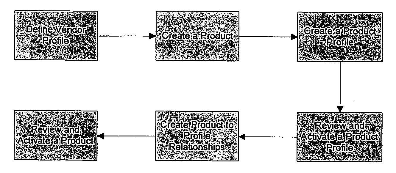
- SDP SMC SCM Service Definition Management
- The Service Definition Management Component manages the Service entity defined in the SDP environment.


- Service Configuration
- The Service and Profiles are created and configured through the SG&C by Administrative User(s). The Service can be created using the following process:
- Define an Organization and Service Provider Profile if the required Service Provider does not already exist. The Service Provider Profile will be created in Active Status.
- Define a Service via the SG&C. It will be created in New Status.
- Define a Service Profile. Select the Attributes from the relevant Product Profiles to include into the Service Profile. The Service Profile will be created in New Status.
- Review and Activate the Service Profile.
- Define a Network Profile. Enter values into the Attributes defined for the Network Profile. The Network Profile will be created in New Status.
- Review and Activate the Network Profile.
- Create Relationships between the Service and the related Profiles. This includes a mandatory relationship with a Service Profile, Service Provider Profile, and Network Profile.
- Review and Activate the Service.
- The Service is available to use for creating Service Variants.

- SDP SMC SCM Service Variant Definition Management
- The Service Variant Definition Management Component manages the Service Variant entity defined in the SDP environment.


- Service Variant Configuration
- The Service Variant and Profiles are created and configured through the SG&C by Administrative User(s). The Service Variant can be created using the following process:
- Select a Service to create a Service Variant on. Define a Service Variant via the SG&C. It will be created in New Status.
- Select a Service Profile from the Service to create an instance off. Assign values to the Attributes based on the criteria specified by the Attribute Masks and Validation Criteria required to maintain data integrity. The instance of the Service Profile will be created in New Status.
- Review and Activate the Service Profile.
- Create Relationships between the Product and the related Profiles. This includes a mandatory relationship with a Service Profile, Service Provider Profile and Network Profile.
- Review and Activate the Service Variant.
- The Service Variant is available to include in Offers

- SDP SMC SCM Offer Definition Management
- The Offer Definition Management Component manages the Offer entity defined in the SDP environment.

- Offer Configuration
- The Offers and Profiles are created and configured through the SG&C by Administrative User(s). The Offer can be created using the following process:
- Define an Offer via the SG&C, by selecting the Service Variants to include in the Offer and assigning Prices. It will be created in New Status.
- Define an Offer Profile. Assign values to the Attributes based on the criteria specified by the Attribute Masks and Validation Criteria required to maintain data integrity. The instance of the Offer Profile will be created in New Status.
- Review and Activate the Offer Profile.
- Create Relationships between the Offer and the related Profiles. This includes a relationship with an Offer Profile.
- Review and Activate the Offer.
- The Offer is available to include in Solutions for subscription purposes.

- SDP SMC SCM Category Definition Management
- The Category Definition Management Component manages the Category entity defined in the SDP environment.


- Category Configuration
- The Categories are created and configured through the SG&C by Administrative User(s). The Category can be created using the following process:
- Define a Product Category by creating a Category with the Category Type indicating Product via the SG&C. It will be created in Active Status.
- Create relationships between the Category and the corresponding Products.
- The Product Category is available to use for retrieving and managing the corresponding Products.

- Define a Service Category by creating a Category with the Category Type indicating Service via the SG&C. It will be created in Active Status.
- Create relationships between the Category and the corresponding Services.
- The Service Category is available to use for retrieving and managing the corresponding Services.

- Define an Offer Category by creating a Category with the Category Type indicating Offer via the SG&C. It will be created in Active Status.
- Create relationships between the Category and the corresponding Offers.
- The Offer Category is available to use for retrieving and managing the corresponding Offers.

- SDP SMC SCM Price Definition Management
- The Price Definition Management Component manages the Price entity defined in the SDP environment.
- Price Relationships
- Offer N/A N/A An Offer contains a relationship with one to many Service Variants. These Service Variants may be based off the same or different Services. Price N/A Mandaton A price contains the pricing information for an Offer. The price contains the value, currency, payment model, and payment term. Multiple prices can be related to a single Offer. Prices are unique


- Price Configuration
- The Prices are created and configured through the SG&C by Administrative User(s) when creating an Offer. The Price can be created using the following process:
- Define a Price for an Offer via the SG&C.
- Enter a Value for the Price.
- Select a Currency for the Price.
- Select a Payment Model for the Price.
- Select a Payment Term for the Price.
- Save the Offer with the defined Price.

- The SDP SMC Service Catalog Management Module consists of a Service Catalog Management (SCM) Processor which exposes Business Capabilities to manage the Service Catalog via Web Services. The SCM Processor has the ability to execute a defined set of tasks for each Business Capability against the APIs exposed by six self-contained Service Catalog Management components.

- Within Service Management and Control Environment, Service Catalog Management (SCM) is composed of:
- Integration Tier: implements workflow according to the web service call that has been received in order to abstract the six components and allow segregation between each of them to facilitate ease of separation in the future. A workflow contains a group of atomic tasks to be executed over Business Tiers.
- Business Tier: implements the atomic business methods, which map to the business tasks that SCM Processor has to invoke in order to respond to web service requests. Atomic actions like Create, Update, Get, Change Status, are implemented taking in account the required business specific logic of each component. Nevertheless, every business method has the same signature that receives and returns an SDP Message, guaranteeing flexibility.
- Data Access Interface: implements an abstraction layer to the Data Access Tier, providing the business tier the same interface regardless of the Data Access Tier class implementation. In this way, the implemented interface methods have access to the other Data Tier Interfaces, permitting access to the whole data in the database schema, but still ensuring the separation between the several database functional blocks.
- Data Access Tier: implements methods that provide a consistent way to access the database. This access is made by means of stored procedures rather than directly accessing the database tables. This provides flexibility to change table's internal structures as well as foreign keys relation without the need of changing the code at all. Only internal implementation of stored procedures will have to be changed.
- SDP SMC SCM Product Definition Management
- The Product Definition Management Component is comprised of 3 classes. These classes encapsulate the functionality necessary to manage the Product entity as defined for the SDP.
- The Product Definition Manager is the Business Tier class that exposes the APIs available to manage the Product. This class accepts and returns an SDP Message object in all instances. In addition to returning the result of the operation, a status and event collection is returned within the SDP Message.
- The Product Data Access Interface provides access to the data required by the Product Definition Manager through enabling the ability to interact with Data Access Tiers of other SMC Components.
- The Product Data Access class provides functionality to manage the Product data stored in the SDP Database. It executes stored procedures against the SDP Database to Create, Retrieve, Update, and Delete Product data. The Product Data Access class also instantiates and populates SDP entities with Product data.
- Product Definition Management

- The Product Definition Management Component provides the following capabilities to the SDP.
- Create Product
- Update Product
- Activate Product
- Inactivate Product
- Suspend Product
- Retrieve Product
- Retrieve Products
- Retrieve Products by Category
- Retrieve Products by Status
- Update Product to Vendor Profile Relationships
- Update Product to Product Profile Relationships
- SDP SMC SCM Service Definition Management
- The Service Definition Management Component is comprised of three classes. These classes encapsulate the functionality necessary to manage the Service entity as defined for the SDP.
- The Service Definition Manager is the Business Tier class that exposes the APIs available to manage the Service. This class accepts and returns an SDP Message object in all instances. In addition to returning the result of the operation, a status and event collection is returned within the SDP Message.
- The Service Data Access Interface provides access to the data required by the Service Definition Manager through enabling the ability to interact with Data Access Tiers of other SMC Components.
- The Service Data Access class provides functionality to manage the Service data stored in the SDP Database. It executes stored procedures against the SDP Database to Create, Retrieve, Update, and Delete Service data. The Service Data Access class also instantiates and populates SDP entities with Service data.

- The Service Definition Management Component provides the following capabilities to the SDP.
- Create Service
- Update Service
- Activate Service
- Inactivate Service
- Suspend Service
- Retrieve Service
- Retrieve Services
- Retrieve Services by Category
- Retrieve Services by Status
- Update Service to Service Profile Relationships
- Update Service to Network Profile Relationships
- Update Service to Service Provider Profile Relationships
- SDP SMC SCM Service Variant Definition Management
- The Service Variant Definition Management Component is comprised of three classes. These classes encapsulate the functionality necessary to manage the Service Variant entity as defined for the SDP.
- The Service Variant Definition Manager is the Business Tier class that exposes the APIs available to manage the Service Variant. This class accepts and returns an SDP Message object in all instances. In addition to returning the result of the operation, a status and event collection is returned within the SDP Message.
- The Service Variant Data Access Interface provides access to the data required by the Service Variant Definition Manager through enabling the ability to interact with Data Access Tiers of other SMC Components.
- The Service Variant Data Access class provides functionality to manage the Service Variant data stored in the SDP Database. It executes stored procedures against the SDP Database to Create, Retrieve, Update, and Delete Service Variant data. The Service Variant Data Access class also instantiates and populates SDP entities with Service Variant data.

- The Service Variant Definition Management Component provides the following capabilities to the SDP.
- Create Service Variant
- Update Service Variant
- Activate Service Variant
- Inactivate Service Variant
- Suspend Service Variant
- Retrieve Service Variant
- Retrieve Service Variants
- Retrieve Service Variants by Service
- Retrieve Service Variants by Status
- Retrieve Service Variants by Service and Status
- Update Service Variant to Service Profile Relationships
- Update Service Variant to Network Profile Relationships
- Update Service Variant to Service Provider Profile Relationships
- SDP SMC SCM Offer Definition Management
- The Offer Definition Management Component is comprised of three classes. These classes encapsulate the functionality necessary to manage the Offer entity as defined for the SDP.
- The Offer Definition Manager is the Business Tier class that exposes the APIs available to manage the Offer. This class accepts and returns an SDP Message object in all instances. In addition to returning the result of the operation, a status and event collection is returned within the SDP Message.
- The Offer Data Access Interface provides access to the data required by the Offer Definition Manager through enabling the ability to interact with Data Access Tiers of other SMC Components.
- The Offer Data Access class provides functionality to manage the Offer data stored in the SDP Database. It executes stored procedures against the SDP Database to Create, Retrieve, Update, and Delete Offer data. The Offer Data Access class also instantiates and populates SDP entities with Offer data.
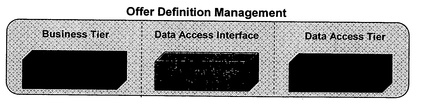
- The Offer Definition Management Component provides the following capabilities to the SDP.
- Create Offer
- Update Offer
- Activate Offer
- Inactivate Offer
- Suspend Offer
- Retrieve Offer
- Retrieve Offers
- Retrieve Offers by Category
- Retrieve Offers by Status
- Update Offer to Offer Profile Relationships
- SDP SMC SCM Category Definition Management
- The Category Definition Management Component is comprised of 3 classes. These classes encapsulate the functionality necessary to manage the Category entity as defined for the SDP.
- The Category Definition Manager is the Business Tier class that exposes the APIs available to manage the Category. This class accepts and returns an SDP Message object in all instances. In addition to returning the result of the operation, a status and event collection is returned within the SDP Message.
- The Category Data Access Interface provides access to the data required by the Category Definition Manager through enabling the ability to interact with Data Access Tiers of other SMC Components.
- The Category Data Access class provides functionality to manage the Category data stored in the SDP Database. It executes stored procedures against the SDP Database to Create, Retrieve, Update, and Delete Category data. The Category Data Access class also instantiates and populates SDP entities with Category data.

- The Category Definition Management Component provides the following capabilities to the SDP.
- Create Category
- Update Category
- Activate Category
- Suspend Category
- Retrieve Category
- Retrieve All Categories
- Retrieve All Product Categories
- Retrieve All Service Categories
- Retrieve All Offer Categories
- Update Category to Product Relationships
- Update Category to Service Relationships
- Update Category to Offer Relationships
- SDP SMC SCM Price Definition Management
- The Price Definition Management Component is comprised of 3 classes. These classes encapsulate the functionality necessary to manage the Price entity as defined for the SDP.
- The Price Definition Manager is the Business Tier class that exposes the APIs available to manage the Price. This class accepts and returns an SDP Message object in all instances. In addition to returning the result of the operation, a status and event collection is returned within the SDP Message.
- The Price Data Access Interface provides access to the data required by the Price Definition Manager through enabling the ability to interact with Data Access Tiers of other SMC Components.
- The Price Data Access class provides functionality to manage the Price data stored in the SDP Database. It executes stored procedures against the SDP Database to Create, Retrieve, Update, and Delete Price data. The Price Data Access class also instantiates and populates SDP entities with Price data.

- The Price Definition Management Component provides the following capabilities to the SDP.
- Create Price
- Update Price
- Activate Price
- Suspend Price
- Retrieve Price
- Create Currency
- Update Currency
- Retrieve Currency
- Retrieve All Currencies
- Create Payment Model
- Update Payment Model
- Retrieve Payment Model
- Retrieve All Payment Models
- Create Payment Method
- Update Payment Method
- Retrieve Payment Method
- Retrieve All Payment Methods
- Create Payment Term
- Update Payment Term
- Retrieve Payment Term
- Retrieve All Payment Terms
- Create Tariff
- Update Tariff
- Retrieve Tariff
- Retrieve All Tariffs
- Subscription Management
- The SDP SMC Subscription Management Module is composed of two major functional entities. Each major functional entity has a Component defined to manage the instances of the entity created on the SDP. The structure and relationships of these entities provide the framework for SDP Subscription Management.

- The Entities defined for Subscription Management are:
- Solution—A Solution contains a subset of the Offers defined within the Service Catalog to be used by an Organization. The Solution provides the ability to limit which Offers are available to an Organization. A Solution may contain many Solution Offers.
- Solution Offer—An instance of the Offer, called a Solution Offer, exists in the Solution to allow the configuration of the Offer to be customized for an Organization by an Administrative User.
- Solution Service Variant—An instance of the Service Variant, called a Solution Service Variant, exists in the Solution Offer to allow the configuration of the Service Variant to be customized for an Organization by an Administrative User.
- Subscription—A Subscription contains an instance of a Solution Offer, called a Subscription Offer, which has been subscribed by a User. A Subscription contains only a single Subscription Offer.
- Subscription Offer—An instance of the Solution Offer, called a Subscription Offer, exists in the Subscription to allow the configuration of the Subscription Offer to be customized for User by the Subscriber or an Administrative User.
- Subscription Service Variant—An instance of the Solution Service Variants, called Subscription Service Variants, exist in the Subscription to allow the configuration of the Subscription Service Variant to be customized by the Subscriber or an Administrative User.
- SDP SMC SM Solution Management
- The Solution Management Component manages the Solution entity defined in the SDP environment.


- Solution Configuration
- The Solutions are created and configured through the SG&C by Administrative User(s).
- The Default Solution for Marketing & Sales is created and configured during setup.
- Define a Default Solution belonging to the Marketing & Sales Organization.
- Upon Offer definition, the Offers will be automatically added as Solution Offers to the Default Solution.

- Custom Solutions for Organizations can be created and configured through the SG&C by Administrative User(s).
- Define a Solution for an Organization.
- Add Solution Offers from the Default Solution to the newly defined Solution.
- Customize Solution Offers or Solution Service Variant attribute values for the Organization.

- SDP SMC SM Subscription Management
- The Subscription Management Component manages the Subscription entity defined in the SDP environment.


- Subscription Configuration
- The Subscription created and configured through multiple channels.
- The Subscription can be created and configured via the Portal by Subscribers.
- Select an Offer to subscribe to from the Portal and submit to SO.

- The Subscription can be created and configured via SMS by Subscribers.
- Enter a Code for subscription corresponding to an Offer to the Message Parser.
- The Message Parser translates to the corresponding Offer and submitted to SO.

- The Subscription can be created and configured via CRM by Agents.
- Pass the Service Type Name for Subscription by a User to the SO via the BSS OSS IF.
- The Subscription to a Solution Offer is created based on the Service Type Name.

- Application Architecture
- The SDP SMC Subscription Management Module consists of a Subscription Management (SM) Processor which exposes Business Capabilities to manage the Solutions and Subscriptions via Web Services. The SM Processor has the ability to execute a defined set of tasks for each Business Capability against the APIs exposed by 3 self-contained Subscription Management components.

- Within Service Management and Control Environment, Subscription Management (SM) is composed of:
- Integration Tier: implements workflow according to the web service call that has been received in order to abstract the three components and allow segregation between each of them to facilitate ease of separation in the future. A workflow contains a group of atomic tasks to be executed over Business Tiers.
- Business Tier: implements the atomic business methods, which map to the business tasks that SCM Processor has to invoke in order to respond to web service requests. Atomic actions like Create, Update, Get, Change Status, are implemented taking in account the required business specific logic of each component. Nevertheless, every business method has the same signature that receives and returns an SDP Message, guaranteeing flexibility.
- Data Access Interface: implements an abstraction layer to the Data Access Tier, providing the business tier the same interface regardless of the Data Access Tier class implementation. In this way, the implemented interface methods have access to the other Data Tier Interfaces, permitting access to the whole data in the database schema, but still ensuring the separation between the several database functional blocks.
- Data Access Tier: implements methods that provide a consistent way to access the database. This access is made by means of stored procedures rather than directly accessing the database tables. This provides flexibility to change table's internal structures as well as foreign keys relation without the need of changing the code at all. Only internal implementation of stored procedures will have to be changed.
- SDP SMC SM Solution Management
- The Solution Management Component is comprised of three classes. These classes encapsulate the functionality necessary to manage the Solution entity as defined for the SDP.
- The Solution Manager is the Business Tier class that exposes the APIs available to manage the Solution. This class accepts and returns an SDP Message object in all instances. In addition to returning the result of the operation, a status and event collection is returned within the SDP Message.
- The Solution Data Access Interface provides access to the data required by the Solution Manager through enabling the ability to interact with Data Access Tiers of other SMC Components.
- The Solution Data Access class provides functionality to manage the Solution data stored in the SDP Database. It executes stored procedures against the SDP Database to Create, Retrieve, Update, and Delete Solution data. The Solution Data Access class also instantiates and populates SDP entities with Solution data.

- The Solution Management Component provides the following capabilities to the SDP.
- Create Solution
- Update Solution
- Activate Solution
- Inactivate Solution
- Suspend Solution
- Retrieve Solution
- Retrieve Solutions
- Retrieve Solutions with Active Solution Offers
- Create Solution Offer in Solution
- Update Solution Offer
- Activate Solution Offer
- Inactivate Solution Offer
- Suspend Solution Offer
- Retrieve Solution Offer
- Retrieve Solution Offers by Status
- ACS for SDP SMC SM Subscription Management
- The Subscription Management Component is comprised of 3 classes. These classes encapsulate the functionality necessary to manage the Subscription entity as defined for the SDP.
- The Subscription Manager is the Business Tier class that exposes the APIs available to manage the Subscription. This class accepts and returns an SDP Message object in all instances. In addition to returning the result of the operation, a status and event collection is returned within the SDP Message.
- The Subscription Data Access Interface provides access to the data required by the Subscription Manager through enabling the ability to interact with Data Access Tiers of other SMC Components.
- The Subscription Data Access class provides functionality to manage the Subscription data stored in the SDP Database. It executes stored procedures against the SDP Database to Create, Retrieve, Update, and Delete Subscription data. The Subscription Data Access class also instantiates and populates SDP entities with Subscription data.

- The Subscription Management Component provides the following capabilities to the SDP.
- Create Subscription
- Update Subscription
- Activate Subscription
- Inactivate Subscription
- Suspend Subscription
- Retrieve Subscription
- Retrieve Subscriptions
- Retrieve Subscriptions By Status
- Update Subscription Offer
- Activate Subscription Offer
- Inactivate Subscription Offer
- Suspend Subscription Offer
- Retrieve Subscription Offer
- Update Subscription Service Variant
- Retrieve Subscription Service Variant
- Retrieve Subscription Service Variants
- Unified User Management
- Functional Architecture
- The ACS SDP SMC Unified Management Module is comprised of 5 major functional entities. There are 2 Components defined to manage the instances of the entities created on the SDP. The structure and relationships of these entities provide the framework for SDP Unified User Management.

- The Entities defined for Unified User Management are:
- Organization—An Organization contains a set of Users. An Organization has a type of at least one of the following: Customer, Reseller, Service Provider. The Organization will contain a reference to the Default solution upon creation. This provides the organization with access to Solution Offers provided by the Marketing & Sales Organization. The Organization may also have a relationship with a unique Solution created for their Organization.
- User—A User belongs to an Organization. It contains one to many Billing Accounts. A User also has associated Roles which list the privileges on the SDP that will be granted to the User.
- Billing Account—The Billing Account contains the billing information provided by the CRM system to the SDP. It specifies the data required to apply charges and bill a user. A Billing Account has Payee and Owner relationships with Subscriptions.
- Roles—A Role contains a list of Privileges that should be granted to a User on the SDP. A User can have multiple Roles and Roles can have multiple Privileges.
- Privileges—A Privilege corresponds to an exposed capability on the SDP. A Privilege can be associated with multiple Roles.
- SDP SMC UUM Directory Management
- The Directory Management Component manages the Organization, User, and Billing Account entities defined in the SDP environment.


- Organization Configuration
- The Organization can be created via the SG&C by Administrative User(s).
- Define an Organization via the SG&C. A Workflow will be executed to create the Organization. It will be created in Active Status. An Organization is created with a Customer Profile by default.
- If the Organization is specified as a Service Provider, Define a Service Provider Profile to link to the Organization.
- Review and Approve the Service Provider Profile.

- The Organization can be created via CRM by Agents
- Define an Organization via CRM through the BSS OSS IF. A Workflow will be executed to create the Organization. It will be created in Active Status. An Organization is created with a Customer Profile by default.


- User Configuration
- Administrative Users can be created and configured through the SG&C by Administrative User(s).
- Define an Administrative User via the SG&C. A Workflow will be executed to create the User under the Organization specified. It will be created in Active Status.
- A User will be created with the Roles assigned through the SG&C.
- User and User Preference Profiles will be created with the data assigned through the SG&C
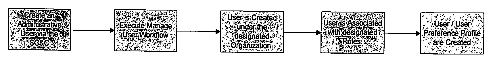
- The Users can be created and configured via CRM by Agents.
- Define a User via CRM through the BSS OSS IF. A Workflow will be executed to create the User. It will be created in Active Status. A User is created with User, User Preference, and BSS OSS Profiles by default.


- Billing Account Configuration
- The Billing Accounts can be created and configured via CRM by Agents.
- Define a Billing Account via CRM through the BSS OSS IF. A Workflow will be executed to create the Billing Account. It will be created in Active Status. A Billing Account is created with Billing and BSS OSS Profiles by default.

- SDP SMC UUM Credential Management
- The Credential Management Component manages the Role and Privilege entities defined in the SDP environment.

- Role Configuration
- Roles can be created and configured through the SG&C by Administrative User(s).
- Define a Role via the SG&C. A request will be submitted to create the Role on the SDP.
- Create relationships between Privileges and the Role.
- Create relationships between Users and the Role.

- Privileges can be created and configured through the SG&C by Administrative User(s).
- Define a Privilege via the SG&C. A request will be submitted to create the Privilege on the SDP.
- Create relationships between an exposed SDP capability and the Privilege.
- Create relationships between Roles and the Privilege.

- Application Architecture
- The ACS SDP SMC Unified User Management Module consists of a Unified User Management (UUM) Processor which exposes Business Capabilities to manage the Organizations, Users, Billing Accounts, Roles, and Privileges via Web Services. The UUM Processor has the ability to execute a defined set of tasks for each Business Capability against the APIs exposed by 2 self-contained Unified User Management components.

- Within Service Management and Control Environment, Unified User Management (UUM) is composed of:
-
- Integration Tier: implements workflow according to the web service call that has been received in order to abstract the three components and allow segregation between each of them to facilitate ease of separation in the future. A workflow contains a group of atomic tasks to be executed over Business Tiers.
- Business Tier: implements the atomic business methods, which map to the business tasks that SCM Processor has to invoke in order to respond to web service requests. Atomic actions like Create, Update, Get, Change Status, are implemented taking in account the required business specific logic of each component. Nevertheless, every business method has the same signature that receives and returns an SDP Message, guaranteeing flexibility.
- Data Access Interface: implements an abstraction layer to the Data Access Tier, providing the business tier the same interface regardless of the Data Access Tier class implementation. In this way, the implemented interface methods have access to the other Data Tier Interfaces, permitting access to the whole data in the database schema, but still ensuring the separation between the several database functional blocks.
- Data Access Tier: implements methods that provide a consistent way to access the database. This access is made by means of stored procedures rather than directly accessing the database tables. This provides flexibility to change table's internal structures as well as foreign keys relation without the need of changing the code at all. Only internal implementation of stored procedures will have to be changed.
- SDP SMC UUM Directory Management
- The Directory Management Component is comprised of three classes. These classes encapsulate the functionality necessary to manage the Directory entity as defined for the SDP.
- The Directory Manager is the Business Tier class that exposes the APIs available to manage the Directory. This class accepts and returns an SDP Message object in all instances. In addition to returning the result of the operation, a status and event collection is returned within the SDP Message.
- The Directory Data Access Interface provides access to the data required by the Directory Manager through enabling the ability to interact with Data Access Tiers of other SMC Components.
- The Directory Data Access class provides functionality to manage the Directory data stored in the SDP Database. It executes stored procedures against the SDP Database to Create, Retrieve, Update, and Delete Directory data. The Directory Data Access class also instantiates and populates SDP entities with Directory data.

- The Directory Management Component provides the following capabilities to the SDP.
- Create Organization
- Update Organization
- Activate Organization
- Inactivate Organization
- Suspend Organization
- Retrieve Organization
- Retrieve Organizations
- Create User
- Update User
- Activate User
- Inactivate User
- Suspend User
- Retrieve User
- Retrieve Users
- Create Billing Account
- Update Billing Account
- Activate Billing Account
- Inactivate Billing Account
- Suspend Billing Account
- Retrieve Billing Account
- Retrieve Billing Accounts
- SDP SMC UUM Credential Management
- The Credential Management Component is comprised of 3 classes. These classes encapsulate the functionality necessary to manage the Credential entity as defined for the SDP.
- The Credential Manager is the Business Tier class that exposes the APIs available to manage the Credential. This class accepts and returns an SDP Message object in all instances. In addition to returning the result of the operation, a status and event collection is returned within the SDP Message.
- The Credential Data Access Interface provides access to the data required by the Credential Manager through enabling the ability to interact with Data Access Tiers of other SMC Components.
- The Credential Data Access class provides functionality to manage the Credential data stored in the SDP Database. It executes stored procedures against the SDP Database to Create, Retrieve, Update, and Delete Credential data. The Credential Data Access class also instantiates and populates SDP entities with Credential data.

- The Credential Management Component provides the following capabilities to the SDP.
- Create Role
- Update Role
- Activate Role
- Inactivate Role
- Suspend Role
- Retrieve Role
- Retrieve Roles
- Retrieve Roles By User
- Create Privilege
- Update Privilege
- Activate Privilege
- Inactivate Privilege
- Suspend Privilege
- Retrieve Privilege
- Retrieve Privileges
- Retrieve Privileges By Role
- These illustrative examples are meant to be illustrative only. The disclosed system and method may be extended beyond these examples and applied to other contexts as well. Those ordinarily skilled in the art will recognize that a wide variety of modifications can be made to the embodiments shown or described while remaining within the scope of the invention.
- It is therefore intended that the foregoing detailed description be regarded as illustrative rather than limiting, and that it be understood that it is the following claims, including all equivalents, that are intended to define the spirit and scope of this invention.
Claims (17)
1. A system for managing delivery of a plurality of unrelated services by one or more service providers, the system comprising:
a service delivery server;
a service delivery database which uses a common data model to combine records for subscribers to all of the plurality of unrelated services; and
a service orchestration platform in data communication with the service delivery server and the service delivery database,
wherein the service orchestration platform enables definition, orchestration, and implementation of the plurality of unrelated services.
2. The system of claim 1 further comprising:
a third party portal for service provision by the one or more service providers to service subscribers.
3. The system of claim 1 wherein the plurality of unrelated services comprise telecommunications services.
4. A service delivery platform (SDP) for managing delivery of a plurality of unrelated services by one or more service providers to service subscribers, the SDP comprising:
a service orchestration and integration environment which manages work flow for services, manages business processes for the service providers and integrates constituent applications;
a service creation environment for creation and modification of services;
a service deployment environment to automatically deploy services; and
a service assurance environment to identify faults in services.
5. The SDP of claim 4 further comprising a unified directory accessible by the service orchestration and integration environment, the service creation environment, the service deployment environment and the service assurance environment.
6. The SDP of claim 5 wherein the unified directory is configured to store Provide information regarding subscriber status, services subscribed by the user and details of user's device to access the subscribed services.
7. The SDP of claim 6 further comprising a database to store data for common access by the service orchestration and integration environment, the service creation environment, the service deployment environment and the service assurance environment.
8. The SDP of claim 6 further comprising a data model defining relations among data stored in the database for subscribers, subscription accounts and related information.
9. The SDP of claim 6 wherein the data model determines data type conversion rules for the data transformations between applications accessing the data stored in the database.
10. A service delivery method comprising:
storing in a common data model data of a service delivery platform about a plurality of telecommunications services, service providers and subscribers;
receiving a request from a service provider for creating a new service;
in response, requesting product definitions from a service catalog;
receiving the product definitions and providing the product definitions to the service provider;
receiving a request for service definitions associated with a selected product definition;
receiving service information for the new service based for the service definitions; and
automatically creating facilities for providing the new service, including extending the common data model information about the new service, the provider of the new service and subscribers to the new service.
11. The method of claim 10 wherein storing data comprises:
storing in a service entity information about a service;
storing in a product entity linked to the service entity, information about a product offered by a service provider; and
storing in a service variant entity linked to the service entity, information about a service variant.
12. The method of claim 11 wherein storing data further comprises:
storing in an offer entity information about a service offer; and
storing in an offer service variant entity a link between the offer entity information and the service entity.
13. The method of claim 11 further comprising:
providing a web service for interaction with the service delivery platform;
receiving the request to create a new service via the web service; and
providing the product definitions via the web service.
14. The method of claim 10 wherein automatically creating facilities comprises:
adding an application to provide the new service; and
mapping an application data model for the added application to the master model without mapping to other existing applications.
15. A service delivery platform for telecommunications services, the service delivery platform comprising:
a service creation environment to create the telecommunication services;
a service deployment environment for managing the telecommunication services in one or more networks;
a service enablement environment to execute the telecommunication services;
a service assurance environment to track and monitor the provision of the telecommunication services; and
a common data model accessible by each respective environment for creating and modifying services and accounts of the service delivery platform.
16. The service delivery platform of claim 15 wherein the service deployment comprises:
a configuration management module to manage attributes and values for a service.
17. The service delivery platform of claim 15 wherein the service enablement environment comprises:
a user interaction space for service users and service providers.
Priority Applications (1)
| Application Number | Priority Date | Filing Date | Title |
|---|---|---|---|
| US11/400,249 US20070150480A1 (en) | 2005-04-11 | 2006-04-07 | Service delivery platform |
Applications Claiming Priority (2)
| Application Number | Priority Date | Filing Date | Title |
|---|---|---|---|
| US67011405P | 2005-04-11 | 2005-04-11 | |
| US11/400,249 US20070150480A1 (en) | 2005-04-11 | 2006-04-07 | Service delivery platform |
Publications (1)
| Publication Number | Publication Date |
|---|---|
| US20070150480A1 true US20070150480A1 (en) | 2007-06-28 |
Family
ID=37450628
Family Applications (3)
| Application Number | Title | Priority Date | Filing Date |
|---|---|---|---|
| US11/399,780 Active 2029-12-25 US8554916B2 (en) | 2005-04-11 | 2006-04-07 | Service delivery platform and development of new client business models |
| US11/400,249 Abandoned US20070150480A1 (en) | 2005-04-11 | 2006-04-07 | Service delivery platform |
| US14/047,861 Active 2026-11-24 US9444930B2 (en) | 2005-04-11 | 2013-10-07 | Service delivery platform and development of new client business models |
Family Applications Before (1)
| Application Number | Title | Priority Date | Filing Date |
|---|---|---|---|
| US11/399,780 Active 2029-12-25 US8554916B2 (en) | 2005-04-11 | 2006-04-07 | Service delivery platform and development of new client business models |
Family Applications After (1)
| Application Number | Title | Priority Date | Filing Date |
|---|---|---|---|
| US14/047,861 Active 2026-11-24 US9444930B2 (en) | 2005-04-11 | 2013-10-07 | Service delivery platform and development of new client business models |
Country Status (2)
| Country | Link |
|---|---|
| US (3) | US8554916B2 (en) |
| AU (2) | AU2006201515A1 (en) |
Cited By (259)
| Publication number | Priority date | Publication date | Assignee | Title |
|---|---|---|---|---|
| US20050021670A1 (en) * | 2003-06-27 | 2005-01-27 | Oracle International Corporation | Method and apparatus for supporting service enablers via service request composition |
| US20060117109A1 (en) * | 2004-12-01 | 2006-06-01 | Oracle International Corporation, A California Corporation | Methods and systems for exposing access network capabilities using an enabler proxy |
| US20060143686A1 (en) * | 2004-12-27 | 2006-06-29 | Oracle International Corporation | Policies as workflows |
| US20060277261A1 (en) * | 2005-06-07 | 2006-12-07 | Microsoft Corporation | Locked receive locations |
| US20070064603A1 (en) * | 2005-09-19 | 2007-03-22 | Sean Chen | Method of provisioning network elements to perform a service |
| US20070276715A1 (en) * | 2006-05-15 | 2007-11-29 | Joerg Beringer | Distributed activity management |
| US20070276714A1 (en) * | 2006-05-15 | 2007-11-29 | Sap Ag | Business process map management |
| US20070288258A1 (en) * | 2006-05-15 | 2007-12-13 | Joerg Beringer | Document instantiation triggering a business action |
| US20080021833A1 (en) * | 2006-07-07 | 2008-01-24 | Microsoft Corporation | Over-the-air delivery of metering certificates and data |
| US20080098099A1 (en) * | 2006-10-23 | 2008-04-24 | Oracle International Corporation | Facilitating Deployment Of Customizations Of Enterprise Applications |
| US20080109867A1 (en) * | 2006-11-07 | 2008-05-08 | Microsoft Corporation | Service and policies for coordinating behaviors and connectivity of a mesh of heterogeneous devices |
| US20080120700A1 (en) * | 2006-11-16 | 2008-05-22 | Nokia Corporation | Attachment solution for multi-access environments |
| US20080120694A1 (en) * | 2006-11-16 | 2008-05-22 | Nokia Corporation | Multi-access authentication in communication system |
| US20080126228A1 (en) * | 2006-11-28 | 2008-05-29 | Keiji Nagai | Order supporting apparatus, control method for an order supporting apparatus, order supporting system, and computer readable storage medium |
| US20080223469A1 (en) * | 2007-03-13 | 2008-09-18 | Hillel David Renassia | Multiple conduit-repair method |
| US20080235354A1 (en) * | 2007-03-23 | 2008-09-25 | Oracle International Corporation | Network agnostic media server control enabler |
| US20080270271A1 (en) * | 2007-04-26 | 2008-10-30 | Axiom Automotive Technologies, Inc. | Method and Computer-Readable Medium for Managing Order Entry |
| US20080275995A1 (en) * | 2007-05-02 | 2008-11-06 | Elevate Technologies Pty Ltd. | Application-Independent Service Delivery |
| US20090041026A1 (en) * | 2007-08-06 | 2009-02-12 | At&T Knowledge Ventures, L.P. | System for configuring network elements |
| WO2009045450A1 (en) * | 2007-10-01 | 2009-04-09 | Grid Dynamics Consulting Services, Inc. | System and method for enabling service transactions |
| US20090112875A1 (en) * | 2007-10-29 | 2009-04-30 | Oracle International Corporation | Shared view of customers across business support systems (bss) and a service delivery platform (sdp) |
| US20090129575A1 (en) * | 2007-11-21 | 2009-05-21 | International Business Machines Corporation | System And Computer Program Product For Creating A Telecommunications Application |
| US20090132717A1 (en) * | 2007-11-20 | 2009-05-21 | Oracle International Corporation | Session initiation protocol-based internet protocol television |
| US20090132220A1 (en) * | 2007-11-21 | 2009-05-21 | International Business Machines Corporation | Method For Creating A Telecommunications Application |
| US7546301B1 (en) * | 2005-08-17 | 2009-06-09 | Alcatel Lucent | Effectuating personalized, process-integrated information, communications and entertainment (ICE) service delivery |
| US20090164833A1 (en) * | 2007-12-19 | 2009-06-25 | Verizon Data Services Inc. | Methods and Systems for Automated Processing of Fallout Orders |
| US20090164500A1 (en) * | 2007-12-20 | 2009-06-25 | Ankur Mathur | System for providing a configurable adaptor for mediating systems |
| US20090171484A1 (en) * | 2007-12-29 | 2009-07-02 | Amx, Llc | Self-describing device module and system and computer-readable medium for the production thereof |
| US20090193057A1 (en) * | 2008-01-24 | 2009-07-30 | Oracle International Corporation | Service-oriented architecture (soa) management of data repository |
| US20090201917A1 (en) * | 2008-02-08 | 2009-08-13 | Oracle International Corporation | Pragmatic approaches to ims |
| US20090210268A1 (en) * | 2008-02-19 | 2009-08-20 | Oracle International Corporation | Bulk order management |
| US20090228469A1 (en) * | 2008-03-05 | 2009-09-10 | Microsoft Corporation | Definition for Service Interface |
| WO2009111855A1 (en) * | 2008-03-13 | 2009-09-17 | Redknee Inc. | Configurator |
| US20090240728A1 (en) * | 2008-03-20 | 2009-09-24 | Microsoft Corporation | Computing environment representation |
| US20090241104A1 (en) * | 2008-03-20 | 2009-09-24 | Microsoft Corporation | Application management within deployable object hierarchy |
| US20090240698A1 (en) * | 2008-03-20 | 2009-09-24 | Microsoft Corporation | Computing environment platform |
| US20090240935A1 (en) * | 2008-03-20 | 2009-09-24 | Microsoft Corporation | Computing environment configuration |
| US7596620B1 (en) * | 2008-11-04 | 2009-09-29 | Aptana, Inc. | System and method for developing, deploying, managing and monitoring a web application in a single environment |
| US20090248729A1 (en) * | 2008-03-25 | 2009-10-01 | Microsoft Corporation | Online application platform and user communities |
| US20090265177A1 (en) * | 2008-04-16 | 2009-10-22 | Gte.Net Llc (D/B/A Verizon Internet Solutions) | Scheduled telecommunication service suspension |
| US20090327300A1 (en) * | 2008-06-26 | 2009-12-31 | Microsoft Corporation | Manifest-based enhanced presence publishing |
| US20100049826A1 (en) * | 2008-08-21 | 2010-02-25 | Oracle International Corporation | In-vehicle multimedia real-time communications |
| US20100077025A1 (en) * | 2008-08-12 | 2010-03-25 | Bank Of America Corporation | Workflow automation & request processing |
| US20100088701A1 (en) * | 2008-10-06 | 2010-04-08 | Sap Ag | Composing and executing service processes |
| US20100107203A1 (en) * | 2008-10-27 | 2010-04-29 | At&T Intellectual Property I, L.P. | Method and apparatus for creating dynamic webpages in a media communication system |
| US20100131326A1 (en) * | 2008-11-24 | 2010-05-27 | International Business Machines Corporation | Identifying a service oriented architecture shared services project |
| US20100153150A1 (en) * | 2008-12-12 | 2010-06-17 | Sap Ag | Software for business adaptation catalog modeling |
| US20100154045A1 (en) * | 2008-09-30 | 2010-06-17 | Microsoft Corporation | Mesh Platform Utility Computing Portal |
| US20100186022A1 (en) * | 2009-01-19 | 2010-07-22 | Alcatel-Lucent Usa, Inc. | System, method and computer readable medium for application placement |
| US20100191656A1 (en) * | 2006-11-27 | 2010-07-29 | Disney Enterprises, Inc. | Systems and methods for interconnecting media services to an interface for transport of media assets |
| CN101808169A (en) * | 2009-02-16 | 2010-08-18 | 埃森哲环球服务有限公司 | Service delivery platform docking station |
| US20100211925A1 (en) * | 2009-02-19 | 2010-08-19 | Interational Business Machines Corporation | Evaluating a service oriented architecture shared services project |
| US20100218162A1 (en) * | 2009-02-25 | 2010-08-26 | International Business Machines Corporation | Constructing a service oriented architecture shared service |
| US20100217634A1 (en) * | 2009-02-25 | 2010-08-26 | International Business Machines Corporation | Transitioning to management of a service oriented architecture shared service |
| US20100217632A1 (en) * | 2009-02-24 | 2010-08-26 | International Business Machines Corporation | Managing service oriented architecture shared services escalation |
| US20100241615A1 (en) * | 2009-03-20 | 2010-09-23 | Microsoft Corporation | Mitigation of obsolescence for archival services |
| US20100251129A1 (en) * | 2009-03-25 | 2010-09-30 | Sap Ag | Data consumption framework for semantic objects |
| US20100312612A1 (en) * | 2007-10-25 | 2010-12-09 | Hugh Carr | Modification of service delivery infrastructure in communication networks |
| US20110022770A1 (en) * | 2002-10-22 | 2011-01-27 | Sullivan Jason A | Systems and methods for providing a dynamically modular processing unit |
| US20110040850A1 (en) * | 2007-05-04 | 2011-02-17 | Microsoft Corporation | Mesh-managing data across a distributed set of devices |
| US7899873B2 (en) | 2008-05-20 | 2011-03-01 | At&T Intellectual Property I, L.P. | System and method of controlling a messaging system |
| US20110054977A1 (en) * | 2009-08-27 | 2011-03-03 | Oracle International Corporation | Customer relationship management using text messages |
| US20110060670A1 (en) * | 2009-09-04 | 2011-03-10 | Hartford Fire Insurance Company | System and method for managing data relating to investments from a variety of sources |
| US20110102991A1 (en) * | 2002-10-22 | 2011-05-05 | Sullivan Jason A | Systems and methods for providing a robust computer processing unit |
| US20110107249A1 (en) * | 2009-10-30 | 2011-05-05 | Cynthia Dolan | Exception Engine For Capacity Planning |
| US20110179147A1 (en) * | 2010-01-15 | 2011-07-21 | Endurance International Group, Inc. | Unaffiliated web domain hosting service based on service pools with flexible resource |
| US7996488B1 (en) * | 2006-11-27 | 2011-08-09 | Disney Enterprises, Inc. | Systems and methods for interconnecting media applications and services with automated workflow orchestration |
| US20110196974A1 (en) * | 2010-02-05 | 2011-08-11 | Oracle International Corporation | Service level cross network coordinated interaction |
| US20110196979A1 (en) * | 2010-02-05 | 2011-08-11 | Oracle International Corporation | Service deliver platform based support of interactions between next generation networks and legacy networks |
| US20110196980A1 (en) * | 2010-02-05 | 2011-08-11 | Oracle International Corporation | Service based consolidation of applications across networks |
| US20110202641A1 (en) * | 2010-02-12 | 2011-08-18 | Colin Kahn | Method and apparatus providing access network aware presence to applications |
| US20110202649A1 (en) * | 2008-09-23 | 2011-08-18 | Electronics And Telecommunications Research Institute | User-centric layered service delivery platform for enabling i-centric services and service providing method using the same |
| US20110199962A1 (en) * | 2010-02-12 | 2011-08-18 | Colin Kahn | Method and apparatus for controlling access technology selection |
| WO2011115471A1 (en) * | 2010-03-18 | 2011-09-22 | Mimos Berhad | Integrated service delivery platform system and method thereof |
| US20110234409A1 (en) * | 2007-11-13 | 2011-09-29 | Elevate Technologies Pty Ltd. | Telemedicine Application for Remote Monitoring, Viewing and Updating of Patient Records |
| CN102215568A (en) * | 2010-04-09 | 2011-10-12 | 华为技术有限公司 | Event scheduling control method, device and system |
| US20110302132A1 (en) * | 2010-06-04 | 2011-12-08 | Swami Muthuvelu | Integrated workflow and database transactions |
| US20110302305A1 (en) * | 2008-09-30 | 2011-12-08 | Tomohiro Morimura | Root cause analysis method, apparatus, and program for it apparatuses from which event information is not obtained |
| US20110307746A1 (en) * | 2010-06-07 | 2011-12-15 | Sullivan Jason A | Systems and Methods for Intelligent and Flexible Management and Monitoring of Computer Systems |
| WO2011160090A1 (en) * | 2010-06-17 | 2011-12-22 | Coral Networks, Inc. | System and method for a computer based forms languace |
| US8086758B1 (en) | 2006-11-27 | 2011-12-27 | Disney Enterprises, Inc. | Systems and methods for interconnecting media applications and services with centralized services |
| US20120041799A1 (en) * | 2010-08-13 | 2012-02-16 | Fuji Xerox Co., Ltd. | Information processing apparatus and computer readable medium |
| US20120041945A1 (en) * | 2010-08-16 | 2012-02-16 | Salesforce.Com, Inc. | Mechanism for facilitating efficient collection and presentation of business activity monitoring data |
| US20120045040A1 (en) * | 2004-05-28 | 2012-02-23 | Oracle International Corporation | True convergence with end to end identity management |
| US20120096162A1 (en) * | 2009-07-09 | 2012-04-19 | Fernando Cecilia Torralba | Methods and apparatuses for initiating provisioning of subscriber data in a hss of an ip multimedia subsystem network |
| US20120106358A1 (en) * | 2010-11-02 | 2012-05-03 | Cisco Technology, Inc. | System and method for providing proactive fault monitoring in a network environment |
| US20120166391A1 (en) * | 2009-09-02 | 2012-06-28 | Zte Corporation | Method and System for Data Synchronization in Content Delivery Network |
| US20120173354A1 (en) * | 2010-12-30 | 2012-07-05 | Verizon Patent And Licensing Inc. | System and method for providing a unified messaging and modeling infrastructure |
| US20120219138A1 (en) * | 2007-02-28 | 2012-08-30 | International Business Machines Corporation | Implementing a contact center using open standards and non-proprietary components |
| US8260845B1 (en) | 2007-11-21 | 2012-09-04 | Appcelerator, Inc. | System and method for auto-generating JavaScript proxies and meta-proxies |
| US8285813B1 (en) | 2007-12-05 | 2012-10-09 | Appcelerator, Inc. | System and method for emulating different user agents on a server |
| US8291079B1 (en) | 2008-06-04 | 2012-10-16 | Appcelerator, Inc. | System and method for developing, deploying, managing and monitoring a web application in a single environment |
| US20120266020A1 (en) * | 2011-04-18 | 2012-10-18 | Manyphay Souvannarath | System, method, and apparatus for resolving errors in a system |
| US8321498B2 (en) | 2005-03-01 | 2012-11-27 | Oracle International Corporation | Policy interface description framework |
| US8335982B1 (en) | 2007-12-05 | 2012-12-18 | Appcelerator, Inc. | System and method for binding a document object model through JavaScript callbacks |
| US20120323922A1 (en) * | 2010-07-13 | 2012-12-20 | International Business Machines Corporation | Data element categorization in a service-oriented architecture |
| US8407331B2 (en) | 2008-02-28 | 2013-03-26 | Microsoft Corporation | Codeless provisioning |
| US20130086479A1 (en) * | 2011-10-01 | 2013-04-04 | Oracle International Corporation | Generating state-driven role-based landing pages |
| US20130091171A1 (en) * | 2011-10-05 | 2013-04-11 | Salesforce.Com, Inc, | Just-in-time user provisioning framework in a multitenant environment |
| US8458703B2 (en) | 2008-06-26 | 2013-06-04 | Oracle International Corporation | Application requesting management function based on metadata for managing enabler or dependency |
| CN103188085A (en) * | 2011-12-27 | 2013-07-03 | 中国电信股份有限公司 | Intelligent maintenance method and system based on enterprise application integration technology |
| US20130183948A1 (en) * | 2010-09-29 | 2013-07-18 | Zte Corporation | Application Store System and Development Method Using the Application Store System |
| US20130227103A1 (en) * | 2012-02-23 | 2013-08-29 | Infosys Limited | End-to-end network service assurance solution |
| US8527860B1 (en) | 2007-12-04 | 2013-09-03 | Appcelerator, Inc. | System and method for exposing the dynamic web server-side |
| US8533773B2 (en) | 2009-11-20 | 2013-09-10 | Oracle International Corporation | Methods and systems for implementing service level consolidated user information management |
| US8539097B2 (en) | 2007-11-14 | 2013-09-17 | Oracle International Corporation | Intelligent message processing |
| US8559341B2 (en) | 2010-11-08 | 2013-10-15 | Cisco Technology, Inc. | System and method for providing a loop free topology in a network environment |
| US8566807B1 (en) | 2007-11-23 | 2013-10-22 | Appcelerator, Inc. | System and method for accessibility of document object model and JavaScript by other platforms |
| US8572602B1 (en) * | 2008-06-05 | 2013-10-29 | Appcelerator, Inc. | System and method for synchronization of a web application to a cloud provider |
| US8583830B2 (en) | 2009-11-19 | 2013-11-12 | Oracle International Corporation | Inter-working with a walled garden floor-controlled system |
| US8639743B1 (en) | 2007-12-05 | 2014-01-28 | Appcelerator, Inc. | System and method for on-the-fly rewriting of JavaScript |
| US20140067940A1 (en) * | 2012-08-31 | 2014-03-06 | Facebook, Inc. | Subscription groups in publish-subscribe system |
| US8670326B1 (en) | 2011-03-31 | 2014-03-11 | Cisco Technology, Inc. | System and method for probing multiple paths in a network environment |
| US20140074540A1 (en) * | 2012-09-07 | 2014-03-13 | Oracle International Corporation | Role assignments in a cloud infrastructure |
| US20140101333A1 (en) * | 2006-12-04 | 2014-04-10 | Oracle International Corporation | System and method for supporting messaging in a fully distributed system |
| US8719451B1 (en) | 2007-11-23 | 2014-05-06 | Appcelerator, Inc. | System and method for on-the-fly, post-processing document object model manipulation |
| CN103782571A (en) * | 2011-07-07 | 2014-05-07 | 思科技术公司 | System and method for providing a message and an event based video services control plane |
| US8724517B1 (en) | 2011-06-02 | 2014-05-13 | Cisco Technology, Inc. | System and method for managing network traffic disruption |
| US8726176B2 (en) | 2007-09-24 | 2014-05-13 | Joerg Beringer | Active business client |
| US8756579B1 (en) | 2007-12-03 | 2014-06-17 | Appcelerator, Inc. | Client-side and server-side unified validation |
| US20140181255A1 (en) * | 2011-08-04 | 2014-06-26 | Jeffery Darrel Thomas | Federation for information technology service management |
| US20140189114A1 (en) * | 2012-12-27 | 2014-07-03 | Benbria Corporation | System And Method For Rule-Based Information Routing And Participation |
| US20140189795A1 (en) * | 2012-03-09 | 2014-07-03 | Huawei Technologies Co., Ltd. | Method and Apparatus for Conducting Service by Service Delivery Platform |
| US8806431B1 (en) | 2007-12-03 | 2014-08-12 | Appecelerator, Inc. | Aspect oriented programming |
| US8819539B1 (en) | 2007-12-03 | 2014-08-26 | Appcelerator, Inc. | On-the-fly rewriting of uniform resource locators in a web-page |
| US8817777B2 (en) * | 2011-08-10 | 2014-08-26 | Microsoft Corporation | Hybrid unified communications deployment between cloud and on-premise |
| US20140245373A1 (en) * | 2013-02-27 | 2014-08-28 | Microsoft Corporation | Discretionary policy management in cloud-based environment |
| US8830875B1 (en) | 2011-06-15 | 2014-09-09 | Cisco Technology, Inc. | System and method for providing a loop free topology in a network environment |
| US20140281909A1 (en) * | 2013-03-14 | 2014-09-18 | Thoughtwire Holdings Corp. | Method and system for generating a view |
| US8879547B2 (en) | 2009-06-02 | 2014-11-04 | Oracle International Corporation | Telephony application services |
| US8880678B1 (en) | 2008-06-05 | 2014-11-04 | Appcelerator, Inc. | System and method for managing and monitoring a web application using multiple cloud providers |
| US8903884B2 (en) | 2011-02-21 | 2014-12-02 | Microsoft Corporation | Multi-tenant services gateway |
| US8914774B1 (en) | 2007-11-15 | 2014-12-16 | Appcelerator, Inc. | System and method for tagging code to determine where the code runs |
| US8914493B2 (en) | 2008-03-10 | 2014-12-16 | Oracle International Corporation | Presence-based event driven architecture |
| US8938491B1 (en) | 2007-12-04 | 2015-01-20 | Appcelerator, Inc. | System and method for secure binding of client calls and server functions |
| US8954989B1 (en) | 2007-11-19 | 2015-02-10 | Appcelerator, Inc. | Flexible, event-driven JavaScript server architecture |
| US8966498B2 (en) | 2008-01-24 | 2015-02-24 | Oracle International Corporation | Integrating operational and business support systems with a service delivery platform |
| US8982733B2 (en) | 2011-03-04 | 2015-03-17 | Cisco Technology, Inc. | System and method for managing topology changes in a network environment |
| US20150095898A1 (en) * | 2013-09-27 | 2015-04-02 | Ford Global Technologies, Llc | Method and Apparatus for Tailored Wireless Module Updating |
| TWI481250B (en) * | 2011-12-29 | 2015-04-11 | Chunghwa Telecom Co Ltd | Value Added Service Network for Process Control Platform |
| US9038082B2 (en) | 2004-05-28 | 2015-05-19 | Oracle International Corporation | Resource abstraction via enabler and metadata |
| US20150180992A1 (en) * | 2013-12-19 | 2015-06-25 | Limelight Networks, Inc. | Content delivery architecture for controlling a digital presence |
| US9128995B1 (en) | 2014-10-09 | 2015-09-08 | Splunk, Inc. | Defining a graphical visualization along a time-based graph lane using key performance indicators derived from machine data |
| US9130895B2 (en) | 2009-10-20 | 2015-09-08 | At&T Intellectual Property I, L.P. | Automatic integrated escalation in a unified messaging system |
| US9130832B1 (en) | 2014-10-09 | 2015-09-08 | Splunk, Inc. | Creating entity definition from a file |
| US20150271028A1 (en) * | 2014-03-22 | 2015-09-24 | Microsoft Corporation | Providing shared account service |
| US9146954B1 (en) | 2014-10-09 | 2015-09-29 | Splunk, Inc. | Creating entity definition from a search result set |
| US9146962B1 (en) | 2014-10-09 | 2015-09-29 | Splunk, Inc. | Identifying events using informational fields |
| US9158811B1 (en) | 2014-10-09 | 2015-10-13 | Splunk, Inc. | Incident review interface |
| WO2015167450A1 (en) * | 2014-04-29 | 2015-11-05 | Hewlett-Packard Development Company, L.P. | Service provisioning |
| US9189510B2 (en) | 2013-02-26 | 2015-11-17 | Facebook, Inc. | System and method for implementing cache consistent regional clusters |
| US9210056B1 (en) | 2014-10-09 | 2015-12-08 | Splunk Inc. | Service monitoring interface |
| US20150363721A1 (en) * | 2014-06-11 | 2015-12-17 | E Service Inc. | Voice over internet protocol relay integration for field service management |
| US9240970B2 (en) | 2012-03-07 | 2016-01-19 | Accenture Global Services Limited | Communication collaboration |
| US9245236B2 (en) | 2006-02-16 | 2016-01-26 | Oracle International Corporation | Factorization of concerns to build a SDP (service delivery platform) |
| US9253113B2 (en) | 2012-09-07 | 2016-02-02 | Oracle International Corporation | Customizable model for throttling and prioritizing orders in a cloud environment |
| US9270759B2 (en) | 2012-02-17 | 2016-02-23 | Blackberry Limited | Method and system for distributing one or more server-based services |
| US9269060B2 (en) | 2009-11-20 | 2016-02-23 | Oracle International Corporation | Methods and systems for generating metadata describing dependencies for composable elements |
| US9277022B2 (en) | 2010-01-15 | 2016-03-01 | Endurance International Group, Inc. | Guided workflows for establishing a web presence |
| US9286491B2 (en) | 2012-06-07 | 2016-03-15 | Amazon Technologies, Inc. | Virtual service provider zones |
| US9288182B1 (en) * | 2012-05-01 | 2016-03-15 | Amazon Technologies, Inc. | Network gateway services and extensions |
| US9294437B1 (en) * | 2012-05-01 | 2016-03-22 | Amazon Technologies, Inc. | Remotely configured network appliances and services |
| US9426500B2 (en) * | 2014-01-15 | 2016-08-23 | Verizon and Redbox Digital Entertainment Services, LLC | Optimal quality adaptive video delivery |
| US9438556B1 (en) | 2012-05-01 | 2016-09-06 | Amazon Technologies, Inc | Flexibly configurable remote network identities |
| US9450846B1 (en) | 2012-10-17 | 2016-09-20 | Cisco Technology, Inc. | System and method for tracking packets in a network environment |
| US9450967B1 (en) | 2012-05-01 | 2016-09-20 | Amazon Technologies, Inc. | Intelligent network service provisioning and maintenance |
| EP3073769A1 (en) * | 2010-04-12 | 2016-09-28 | Synchronoss Technologies, Inc. | System and method for intermediating between subscriber devices and communication service providers |
| US9467355B2 (en) | 2012-09-07 | 2016-10-11 | Oracle International Corporation | Service association model |
| US9491059B2 (en) | 2014-10-09 | 2016-11-08 | Splunk Inc. | Topology navigator for IT services |
| US20160328128A1 (en) * | 2015-05-08 | 2016-11-10 | Avaya Inc. | Pulling graphical user interface widgets for communication devices |
| US9503407B2 (en) | 2009-12-16 | 2016-11-22 | Oracle International Corporation | Message forwarding |
| US9509790B2 (en) | 2009-12-16 | 2016-11-29 | Oracle International Corporation | Global presence |
| US9542400B2 (en) | 2012-09-07 | 2017-01-10 | Oracle International Corporation | Service archive support |
| US9608958B2 (en) | 2013-03-12 | 2017-03-28 | Oracle International Corporation | Lightweight directory access protocol (LDAP) join search mechanism |
| US9621435B2 (en) | 2012-09-07 | 2017-04-11 | Oracle International Corporation | Declarative and extensible model for provisioning of cloud based services |
| US9654515B2 (en) | 2008-01-23 | 2017-05-16 | Oracle International Corporation | Service oriented architecture-based SCIM platform |
| US9667470B2 (en) | 2012-09-07 | 2017-05-30 | Oracle International Corporation | Failure handling in the execution flow of provisioning operations in a cloud environment |
| US20170235623A1 (en) * | 2016-02-16 | 2017-08-17 | International Business Machines Corporation | Event relationship analysis in fault management |
| US9742843B2 (en) | 2013-03-14 | 2017-08-22 | Thoughtwire Holdings Corp. | Method and system for enabling data sharing between software systems |
| US20170272891A1 (en) * | 2010-07-21 | 2017-09-21 | Sensoriant, Inc. | System and method for provisioning user computing devices based on sensor and state information |
| US9817680B1 (en) | 2008-08-04 | 2017-11-14 | Open Invention Network, Llc | Application configuration tool |
| US9838370B2 (en) | 2012-09-07 | 2017-12-05 | Oracle International Corporation | Business attribute driven sizing algorithms |
| US20170373869A1 (en) * | 2015-05-20 | 2017-12-28 | Tencent Technology (Shenzhen) Company Limited | Method, apparatus, and system for providing specified communications service, and terminal |
| US9860329B2 (en) | 2015-07-07 | 2018-01-02 | International Business Machines Corporation | Determining customized audio services |
| US9883008B2 (en) | 2010-01-15 | 2018-01-30 | Endurance International Group, Inc. | Virtualization of multiple distinct website hosting architectures |
| US9882914B1 (en) * | 2015-02-25 | 2018-01-30 | Workday, Inc. | Security group authentication |
| WO2018035554A1 (en) * | 2016-08-24 | 2018-03-01 | Selfserveme Pty Ltd | Customer service systems and portals |
| US9930522B2 (en) | 2010-07-21 | 2018-03-27 | Sensoriant, Inc. | System and method for controlling mobile services using sensor information |
| US9942202B2 (en) | 2015-09-08 | 2018-04-10 | Microsoft Technology Licensing, Llc | Trust status of a communication session |
| US9940112B2 (en) * | 2014-11-06 | 2018-04-10 | Capgemini Technology Services India Limited | Efficient framework for deploying middleware services |
| US9961788B2 (en) | 2002-10-22 | 2018-05-01 | Atd Ventures, Llc | Non-peripherals processing control module having improved heat dissipating properties |
| US9967351B2 (en) | 2015-01-31 | 2018-05-08 | Splunk Inc. | Automated service discovery in I.T. environments |
| US10075494B2 (en) | 2015-05-08 | 2018-09-11 | Avaya Inc. | Pushing graphical user interface widgets for communication devices |
| US10075471B2 (en) | 2012-06-07 | 2018-09-11 | Amazon Technologies, Inc. | Data loss prevention techniques |
| US10084818B1 (en) * | 2012-06-07 | 2018-09-25 | Amazon Technologies, Inc. | Flexibly configurable data modification services |
| US10097426B1 (en) * | 2009-12-21 | 2018-10-09 | Amdocs Development Limited | System, method, and computer program for managing services for a service provider at a device within proximity to a location of the service provider, utilizing logic of a centralized environment |
| US20180341508A1 (en) * | 2017-05-26 | 2018-11-29 | Cognizant Technology Solutions India Pvt. Ltd. | System and method for agent based centralized and efficient transaction recordings for service virtualization |
| US10148530B2 (en) | 2012-09-07 | 2018-12-04 | Oracle International Corporation | Rule based subscription cloning |
| US20180359211A1 (en) * | 2017-06-09 | 2018-12-13 | Walmart Apollo, Llc | Systems and methods for a communication system |
| US10164901B2 (en) | 2014-08-22 | 2018-12-25 | Oracle International Corporation | Intelligent data center selection |
| US10181148B2 (en) | 2010-07-21 | 2019-01-15 | Sensoriant, Inc. | System and method for control and management of resources for consumers of information |
| US10193775B2 (en) | 2014-10-09 | 2019-01-29 | Splunk Inc. | Automatic event group action interface |
| US10198155B2 (en) | 2015-01-31 | 2019-02-05 | Splunk Inc. | Interface for automated service discovery in I.T. environments |
| US10209956B2 (en) | 2014-10-09 | 2019-02-19 | Splunk Inc. | Automatic event group actions |
| US10235638B2 (en) | 2014-10-09 | 2019-03-19 | Splunk Inc. | Adaptive key performance indicator thresholds |
| US10237355B2 (en) * | 2015-05-12 | 2019-03-19 | Equinix, Inc. | Software-controlled cloud exchange |
| US20190108331A1 (en) * | 2017-10-05 | 2019-04-11 | Micro Focus Software Inc. | Real-time monitoring and alerting for directory object update processing |
| US20190138994A1 (en) * | 2017-09-27 | 2019-05-09 | Krishan Deegalla | System and method for implementing an integrated b2b digital mobile customer experience |
| US10289525B2 (en) * | 2017-08-21 | 2019-05-14 | Amadeus S.A.S. | Multi-layer design response time calculator |
| US10296300B2 (en) * | 2008-01-10 | 2019-05-21 | At&T Services, Inc. | Aiding creation of service offers associated with a service delivery framework |
| US10305758B1 (en) | 2014-10-09 | 2019-05-28 | Splunk Inc. | Service monitoring interface reflecting by-service mode |
| US10313329B2 (en) * | 2007-11-15 | 2019-06-04 | Salesforce.Com, Inc. | On-demand service security system and method for managing a risk of access as a condition of permitting access to the on-demand service |
| US10390289B2 (en) | 2014-07-11 | 2019-08-20 | Sensoriant, Inc. | Systems and methods for mediating representations allowing control of devices located in an environment having broadcasting devices |
| US10417108B2 (en) | 2015-09-18 | 2019-09-17 | Splunk Inc. | Portable control modules in a machine data driven service monitoring system |
| US10417225B2 (en) | 2015-09-18 | 2019-09-17 | Splunk Inc. | Entity detail monitoring console |
| US10447555B2 (en) | 2014-10-09 | 2019-10-15 | Splunk Inc. | Aggregate key performance indicator spanning multiple services |
| US10474680B2 (en) | 2014-10-09 | 2019-11-12 | Splunk Inc. | Automatic entity definitions |
| US10503348B2 (en) | 2014-10-09 | 2019-12-10 | Splunk Inc. | Graphical user interface for static and adaptive thresholds |
| US10505825B1 (en) | 2014-10-09 | 2019-12-10 | Splunk Inc. | Automatic creation of related event groups for IT service monitoring |
| US10521746B2 (en) | 2012-09-07 | 2019-12-31 | Oracle International Corporation | Recovery workflow for processing subscription orders in a computing infrastructure system |
| US10536353B2 (en) | 2014-10-09 | 2020-01-14 | Splunk Inc. | Control interface for dynamic substitution of service monitoring dashboard source data |
| US10565241B2 (en) | 2014-10-09 | 2020-02-18 | Splunk Inc. | Defining a new correlation search based on fluctuations in key performance indicators displayed in graph lanes |
| US10592093B2 (en) | 2014-10-09 | 2020-03-17 | Splunk Inc. | Anomaly detection |
| US10614473B2 (en) | 2014-07-11 | 2020-04-07 | Sensoriant, Inc. | System and method for mediating representations with respect to user preferences |
| WO2020117866A1 (en) * | 2018-12-07 | 2020-06-11 | Paypal, Inc. | Unified transaction services for multi-tenant architectures |
| US10701165B2 (en) | 2015-09-23 | 2020-06-30 | Sensoriant, Inc. | Method and system for using device states and user preferences to create user-friendly environments |
| US10778652B2 (en) * | 2018-07-31 | 2020-09-15 | Bae Systems Information And Electronic Systems Integration Inc. | Secure computational workflows |
| US10810055B1 (en) * | 2017-12-14 | 2020-10-20 | Amazon Technologies, Inc. | Request simulation for ensuring compliance |
| US10942960B2 (en) | 2016-09-26 | 2021-03-09 | Splunk Inc. | Automatic triage model execution in machine data driven monitoring automation apparatus with visualization |
| US10942946B2 (en) | 2016-09-26 | 2021-03-09 | Splunk, Inc. | Automatic triage model execution in machine data driven monitoring automation apparatus |
| US10951625B2 (en) | 2018-06-29 | 2021-03-16 | Accenture Global Solutions Limited | Cross-application identity and access management |
| US11030329B2 (en) | 2018-06-15 | 2021-06-08 | Paypal, Inc. | Unified identity services for multi-tenant architectures |
| US11042884B2 (en) * | 2004-05-25 | 2021-06-22 | International Business Machines Corporation | Method and apparatus for using meta-rules to support dynamic rule-based business systems |
| US11055719B2 (en) | 2018-06-15 | 2021-07-06 | Paypal, Inc. | Multi-tenant dispute services |
| US11087263B2 (en) | 2014-10-09 | 2021-08-10 | Splunk Inc. | System monitoring with key performance indicators from shared base search of machine data |
| US11093518B1 (en) | 2017-09-23 | 2021-08-17 | Splunk Inc. | Information technology networked entity monitoring with dynamic metric and threshold selection |
| US11106442B1 (en) | 2017-09-23 | 2021-08-31 | Splunk Inc. | Information technology networked entity monitoring with metric selection prior to deployment |
| US11113675B2 (en) * | 2018-06-15 | 2021-09-07 | Paypal, Inc. | Unified transaction services for multi-tenant architectures |
| WO2021226530A1 (en) * | 2020-05-08 | 2021-11-11 | Microsoft Technology Licensing, Llc | Systems and methods for providing an interface to an external charging system in a digital telecommunications network |
| US11200130B2 (en) | 2015-09-18 | 2021-12-14 | Splunk Inc. | Automatic entity control in a machine data driven service monitoring system |
| US11275775B2 (en) | 2014-10-09 | 2022-03-15 | Splunk Inc. | Performing search queries for key performance indicators using an optimized common information model |
| US11296955B1 (en) | 2014-10-09 | 2022-04-05 | Splunk Inc. | Aggregate key performance indicator spanning multiple services and based on a priority value |
| US11336453B2 (en) | 2018-06-15 | 2022-05-17 | Paypal, Inc. | Transactions between services in a multi-tenant architecture |
| WO2022125369A1 (en) * | 2020-12-08 | 2022-06-16 | M3G Technology, Inc. | Managing conversations for service delivery networks |
| US11368370B2 (en) * | 2016-08-24 | 2022-06-21 | Huawei Technologies Co., Ltd. | Service orchestration method and apparatus, and service provisioning method and apparatus |
| US11455590B2 (en) | 2014-10-09 | 2022-09-27 | Splunk Inc. | Service monitoring adaptation for maintenance downtime |
| US11470166B2 (en) | 2018-06-15 | 2022-10-11 | Paypal, Inc. | Multi-tenant marketplace architectures |
| US20220329496A1 (en) * | 2019-06-03 | 2022-10-13 | Zte Corporation | Service data management method and apparatus for sbb, device and storage medium |
| US11501238B2 (en) | 2014-10-09 | 2022-11-15 | Splunk Inc. | Per-entity breakdown of key performance indicators |
| US11520618B2 (en) * | 2019-12-27 | 2022-12-06 | Paypal, Inc. | System and method for the segmentation of a processor architecture platform solution |
| WO2023003875A1 (en) * | 2021-07-19 | 2023-01-26 | ServiceTitan, Inc. | Automated generation of service item recommendations |
| US11586456B2 (en) | 2018-06-15 | 2023-02-21 | Paypal, Inc. | Agency and regulation modeling for transactions in multi-tenant systems |
| US20230070063A1 (en) * | 2021-09-09 | 2023-03-09 | Dell Products L.P. | Workflow automation utilizing metadata structure |
| US20230153128A1 (en) * | 2020-04-09 | 2023-05-18 | Grypp Corp Limited | Interactive computing resource |
| US11671312B2 (en) | 2014-10-09 | 2023-06-06 | Splunk Inc. | Service detail monitoring console |
| US11676072B1 (en) | 2021-01-29 | 2023-06-13 | Splunk Inc. | Interface for incorporating user feedback into training of clustering model |
| US11734658B2 (en) | 2018-06-15 | 2023-08-22 | Paypal, Inc. | Transactions between services in a multi-tenant architecture |
| US11755559B1 (en) | 2014-10-09 | 2023-09-12 | Splunk Inc. | Automatic entity control in a machine data driven service monitoring system |
| US11843528B2 (en) | 2017-09-25 | 2023-12-12 | Splunk Inc. | Lower-tier application deployment for higher-tier system |
Families Citing this family (11)
| Publication number | Priority date | Publication date | Assignee | Title |
|---|---|---|---|---|
| US10122862B2 (en) * | 2006-12-29 | 2018-11-06 | Ubiquity Software Corporation Limited | Systems and methods for connecting heterogeneous networks |
| US8611370B2 (en) * | 2009-11-13 | 2013-12-17 | At&T Intellectual Property I, L.P. | System and method to provide bundled services through a communication device |
| US9256717B2 (en) * | 2012-03-02 | 2016-02-09 | Verizon Patent And Licensing Inc. | Managed mobile media platform systems and methods |
| US9697524B1 (en) * | 2012-05-24 | 2017-07-04 | Jpmorgan Chase Bank, N.A. | Enterprise fulfillment system with dynamic prefetching capabilities |
| WO2014071626A1 (en) * | 2012-11-12 | 2014-05-15 | 华为技术有限公司 | Method and platform for implementing service capability sharing |
| MX2019008012A (en) | 2017-01-04 | 2020-02-05 | Walmart Apollo Llc | Delegate item delivery. |
| US10555258B2 (en) | 2017-03-13 | 2020-02-04 | At&T Intellectual Property I, L.P. | User-centric ecosystem for heterogeneous connected devices |
| SG11201909527YA (en) * | 2017-04-21 | 2019-11-28 | Hemant Passi | Reseller exchange system |
| CN112561455B (en) * | 2019-09-26 | 2023-09-22 | 腾讯科技(深圳)有限公司 | Business application control system and business application control method |
| US11250484B2 (en) * | 2019-11-18 | 2022-02-15 | Verizon Patent And Licensing Inc. | Systems and methods for secure assisted order generation |
| CN111556205A (en) * | 2020-04-21 | 2020-08-18 | 北京思特奇信息技术股份有限公司 | Method and system for recommending telecommunication products to target users |
Citations (11)
| Publication number | Priority date | Publication date | Assignee | Title |
|---|---|---|---|---|
| US20030005034A1 (en) * | 2001-06-14 | 2003-01-02 | Amin Rajesh B. | System and method for service delivery platform in an IP centric distributed next generation network |
| US20030051041A1 (en) * | 2001-08-07 | 2003-03-13 | Tatara Systems, Inc. | Method and apparatus for integrating billing and authentication functions in local area and wide area wireless data networks |
| US20040111506A1 (en) * | 2002-12-10 | 2004-06-10 | International Business Machines Corporation | System and method for managing web utility services |
| US20040151192A1 (en) * | 2003-01-31 | 2004-08-05 | Dirk Trossen | Service subscription in a communication system |
| US20050102675A1 (en) * | 2003-11-10 | 2005-05-12 | Parkyn Nicholas D. | Method for managing execution of a process based on available services |
| US20050114367A1 (en) * | 2002-10-23 | 2005-05-26 | Medialingua Group | Method and system for getting on-line status, authentication, verification, authorization, communication and transaction services for Web-enabled hardware and software, based on uniform telephone address, as well as method of digital certificate (DC) composition, issuance and management providing multitier DC distribution model and multiple accounts access based on the use of DC and public key infrastructure (PKI) |
| US20050262194A1 (en) * | 2003-08-27 | 2005-11-24 | Ascential Software Corporation | User interface service for a services oriented architecture in a data integration platform |
| US20060047709A1 (en) * | 2001-09-05 | 2006-03-02 | Belin Sven J | Technology independent information management |
| US7092696B1 (en) * | 1998-10-13 | 2006-08-15 | Nortel Networks Limited | Accounting method and apparatus for communications network |
| US7506040B1 (en) * | 2001-06-29 | 2009-03-17 | Symantec Operating Corporation | System and method for storage area network management |
| US7574495B1 (en) * | 2000-09-13 | 2009-08-11 | Fortinet, Inc. | System and method for managing interworking communications protocols |
Family Cites Families (6)
| Publication number | Priority date | Publication date | Assignee | Title |
|---|---|---|---|---|
| CA2683230C (en) * | 1995-02-13 | 2013-08-27 | Intertrust Technologies Corporation | Systems and methods for secure transaction management and electronic rights protection |
| US7133846B1 (en) * | 1995-02-13 | 2006-11-07 | Intertrust Technologies Corp. | Digital certificate support system, methods and techniques for secure electronic commerce transaction and rights management |
| US20040019900A1 (en) * | 2002-07-23 | 2004-01-29 | Philip Knightbridge | Integration platform for interactive communications and management of video on demand services |
| US20050262193A1 (en) * | 2003-08-27 | 2005-11-24 | Ascential Software Corporation | Logging service for a services oriented architecture in a data integration platform |
| US8041760B2 (en) * | 2003-08-27 | 2011-10-18 | International Business Machines Corporation | Service oriented architecture for a loading function in a data integration platform |
| US8060553B2 (en) * | 2003-08-27 | 2011-11-15 | International Business Machines Corporation | Service oriented architecture for a transformation function in a data integration platform |
-
2006
- 2006-04-07 US US11/399,780 patent/US8554916B2/en active Active
- 2006-04-07 US US11/400,249 patent/US20070150480A1/en not_active Abandoned
- 2006-04-11 AU AU2006201515A patent/AU2006201515A1/en not_active Abandoned
- 2006-04-11 AU AU2006201516A patent/AU2006201516B2/en not_active Ceased
-
2013
- 2013-10-07 US US14/047,861 patent/US9444930B2/en active Active
Patent Citations (11)
| Publication number | Priority date | Publication date | Assignee | Title |
|---|---|---|---|---|
| US7092696B1 (en) * | 1998-10-13 | 2006-08-15 | Nortel Networks Limited | Accounting method and apparatus for communications network |
| US7574495B1 (en) * | 2000-09-13 | 2009-08-11 | Fortinet, Inc. | System and method for managing interworking communications protocols |
| US20030005034A1 (en) * | 2001-06-14 | 2003-01-02 | Amin Rajesh B. | System and method for service delivery platform in an IP centric distributed next generation network |
| US7506040B1 (en) * | 2001-06-29 | 2009-03-17 | Symantec Operating Corporation | System and method for storage area network management |
| US20030051041A1 (en) * | 2001-08-07 | 2003-03-13 | Tatara Systems, Inc. | Method and apparatus for integrating billing and authentication functions in local area and wide area wireless data networks |
| US20060047709A1 (en) * | 2001-09-05 | 2006-03-02 | Belin Sven J | Technology independent information management |
| US20050114367A1 (en) * | 2002-10-23 | 2005-05-26 | Medialingua Group | Method and system for getting on-line status, authentication, verification, authorization, communication and transaction services for Web-enabled hardware and software, based on uniform telephone address, as well as method of digital certificate (DC) composition, issuance and management providing multitier DC distribution model and multiple accounts access based on the use of DC and public key infrastructure (PKI) |
| US20040111506A1 (en) * | 2002-12-10 | 2004-06-10 | International Business Machines Corporation | System and method for managing web utility services |
| US20040151192A1 (en) * | 2003-01-31 | 2004-08-05 | Dirk Trossen | Service subscription in a communication system |
| US20050262194A1 (en) * | 2003-08-27 | 2005-11-24 | Ascential Software Corporation | User interface service for a services oriented architecture in a data integration platform |
| US20050102675A1 (en) * | 2003-11-10 | 2005-05-12 | Parkyn Nicholas D. | Method for managing execution of a process based on available services |
Cited By (498)
| Publication number | Priority date | Publication date | Assignee | Title |
|---|---|---|---|---|
| US20110102991A1 (en) * | 2002-10-22 | 2011-05-05 | Sullivan Jason A | Systems and methods for providing a robust computer processing unit |
| US10849245B2 (en) | 2002-10-22 | 2020-11-24 | Atd Ventures, Llc | Systems and methods for providing a robust computer processing unit |
| US8976513B2 (en) | 2002-10-22 | 2015-03-10 | Jason A. Sullivan | Systems and methods for providing a robust computer processing unit |
| US9606577B2 (en) | 2002-10-22 | 2017-03-28 | Atd Ventures Llc | Systems and methods for providing a dynamically modular processing unit |
| US10285293B2 (en) | 2002-10-22 | 2019-05-07 | Atd Ventures, Llc | Systems and methods for providing a robust computer processing unit |
| US9961788B2 (en) | 2002-10-22 | 2018-05-01 | Atd Ventures, Llc | Non-peripherals processing control module having improved heat dissipating properties |
| US20110022770A1 (en) * | 2002-10-22 | 2011-01-27 | Sullivan Jason A | Systems and methods for providing a dynamically modular processing unit |
| US11751350B2 (en) | 2002-10-22 | 2023-09-05 | Atd Ventures, Llc | Systems and methods for providing a robust computer processing unit |
| US20050021670A1 (en) * | 2003-06-27 | 2005-01-27 | Oracle International Corporation | Method and apparatus for supporting service enablers via service request composition |
| US7873716B2 (en) | 2003-06-27 | 2011-01-18 | Oracle International Corporation | Method and apparatus for supporting service enablers via service request composition |
| US11042884B2 (en) * | 2004-05-25 | 2021-06-22 | International Business Machines Corporation | Method and apparatus for using meta-rules to support dynamic rule-based business systems |
| US9038082B2 (en) | 2004-05-28 | 2015-05-19 | Oracle International Corporation | Resource abstraction via enabler and metadata |
| US20120045040A1 (en) * | 2004-05-28 | 2012-02-23 | Oracle International Corporation | True convergence with end to end identity management |
| US9565297B2 (en) * | 2004-05-28 | 2017-02-07 | Oracle International Corporation | True convergence with end to end identity management |
| US20060117109A1 (en) * | 2004-12-01 | 2006-06-01 | Oracle International Corporation, A California Corporation | Methods and systems for exposing access network capabilities using an enabler proxy |
| US7860490B2 (en) | 2004-12-01 | 2010-12-28 | Oracle International Corporation | Methods and systems for exposing access network capabilities using an enabler proxy |
| US20060143686A1 (en) * | 2004-12-27 | 2006-06-29 | Oracle International Corporation | Policies as workflows |
| US8032920B2 (en) | 2004-12-27 | 2011-10-04 | Oracle International Corporation | Policies as workflows |
| US8321498B2 (en) | 2005-03-01 | 2012-11-27 | Oracle International Corporation | Policy interface description framework |
| US8010608B2 (en) * | 2005-06-07 | 2011-08-30 | Microsoft Corporation | Locked receive locations |
| US20060277261A1 (en) * | 2005-06-07 | 2006-12-07 | Microsoft Corporation | Locked receive locations |
| US7546301B1 (en) * | 2005-08-17 | 2009-06-09 | Alcatel Lucent | Effectuating personalized, process-integrated information, communications and entertainment (ICE) service delivery |
| US20070064603A1 (en) * | 2005-09-19 | 2007-03-22 | Sean Chen | Method of provisioning network elements to perform a service |
| US9245236B2 (en) | 2006-02-16 | 2016-01-26 | Oracle International Corporation | Factorization of concerns to build a SDP (service delivery platform) |
| US8527313B2 (en) * | 2006-05-15 | 2013-09-03 | Sap Ag | Document instantiation triggering a business action |
| US20070288258A1 (en) * | 2006-05-15 | 2007-12-13 | Joerg Beringer | Document instantiation triggering a business action |
| US20070276714A1 (en) * | 2006-05-15 | 2007-11-29 | Sap Ag | Business process map management |
| US20070276715A1 (en) * | 2006-05-15 | 2007-11-29 | Joerg Beringer | Distributed activity management |
| US20110173321A1 (en) * | 2006-07-07 | 2011-07-14 | Microsoft Corporation | Over-the-air delivery of metering certificates and data |
| US9009077B2 (en) | 2006-07-07 | 2015-04-14 | Microsoft Technology Licensing, Llc | Over-the-air delivery of metering certificates and data |
| US20080021833A1 (en) * | 2006-07-07 | 2008-01-24 | Microsoft Corporation | Over-the-air delivery of metering certificates and data |
| US7917440B2 (en) * | 2006-07-07 | 2011-03-29 | Microsoft Corporation | Over-the-air delivery of metering certificates and data |
| US9251498B2 (en) * | 2006-10-23 | 2016-02-02 | Oracle International Corporation | Facilitating deployment of customizations of enterprise applications |
| US20080098099A1 (en) * | 2006-10-23 | 2008-04-24 | Oracle International Corporation | Facilitating Deployment Of Customizations Of Enterprise Applications |
| US20080109867A1 (en) * | 2006-11-07 | 2008-05-08 | Microsoft Corporation | Service and policies for coordinating behaviors and connectivity of a mesh of heterogeneous devices |
| US8893231B2 (en) | 2006-11-16 | 2014-11-18 | Nokia Corporation | Multi-access authentication in communication system |
| US20080120694A1 (en) * | 2006-11-16 | 2008-05-22 | Nokia Corporation | Multi-access authentication in communication system |
| US7870601B2 (en) * | 2006-11-16 | 2011-01-11 | Nokia Corporation | Attachment solution for multi-access environments |
| US20080120700A1 (en) * | 2006-11-16 | 2008-05-22 | Nokia Corporation | Attachment solution for multi-access environments |
| US8086758B1 (en) | 2006-11-27 | 2011-12-27 | Disney Enterprises, Inc. | Systems and methods for interconnecting media applications and services with centralized services |
| US20100191656A1 (en) * | 2006-11-27 | 2010-07-29 | Disney Enterprises, Inc. | Systems and methods for interconnecting media services to an interface for transport of media assets |
| US8150929B2 (en) | 2006-11-27 | 2012-04-03 | Disney Enterprises, Inc. | Systems and methods for interconnecting media services to an interface for transport of media assets |
| US7996488B1 (en) * | 2006-11-27 | 2011-08-09 | Disney Enterprises, Inc. | Systems and methods for interconnecting media applications and services with automated workflow orchestration |
| US20080126228A1 (en) * | 2006-11-28 | 2008-05-29 | Keiji Nagai | Order supporting apparatus, control method for an order supporting apparatus, order supporting system, and computer readable storage medium |
| US8954350B2 (en) * | 2006-11-28 | 2015-02-10 | Ricoh Company, Ltd. | Order supporting apparatus, control method for an order supporting apparatus, order supporting system, and computer readable storage medium |
| US9369382B2 (en) * | 2006-12-04 | 2016-06-14 | Oracle International Corporation | System and method for supporting messaging in a fully distributed system |
| US20140101333A1 (en) * | 2006-12-04 | 2014-04-10 | Oracle International Corporation | System and method for supporting messaging in a fully distributed system |
| US20120219138A1 (en) * | 2007-02-28 | 2012-08-30 | International Business Machines Corporation | Implementing a contact center using open standards and non-proprietary components |
| US8675859B2 (en) * | 2007-02-28 | 2014-03-18 | International Business Machines Corporation | Implementing a contact center using open standards and non-proprietary components |
| US20080223469A1 (en) * | 2007-03-13 | 2008-09-18 | Hillel David Renassia | Multiple conduit-repair method |
| US20080235354A1 (en) * | 2007-03-23 | 2008-09-25 | Oracle International Corporation | Network agnostic media server control enabler |
| US8744055B2 (en) | 2007-03-23 | 2014-06-03 | Oracle International Corporation | Abstract application dispatcher |
| US8214503B2 (en) | 2007-03-23 | 2012-07-03 | Oracle International Corporation | Factoring out dialog control and call control |
| US8675852B2 (en) | 2007-03-23 | 2014-03-18 | Oracle International Corporation | Using location as a presence attribute |
| US7853647B2 (en) | 2007-03-23 | 2010-12-14 | Oracle International Corporation | Network agnostic media server control enabler |
| US8230449B2 (en) | 2007-03-23 | 2012-07-24 | Oracle International Corporation | Call control enabler abstracted from underlying network technologies |
| US8321594B2 (en) | 2007-03-23 | 2012-11-27 | Oracle International Corporation | Achieving low latencies on network events in a non-real time platform |
| US20080270271A1 (en) * | 2007-04-26 | 2008-10-30 | Axiom Automotive Technologies, Inc. | Method and Computer-Readable Medium for Managing Order Entry |
| US20080275995A1 (en) * | 2007-05-02 | 2008-11-06 | Elevate Technologies Pty Ltd. | Application-Independent Service Delivery |
| US8667156B2 (en) * | 2007-05-02 | 2014-03-04 | Elevate Technologies Pty Ltd. | Application-independent service delivery |
| US9135279B2 (en) | 2007-05-04 | 2015-09-15 | Microsoft Technology Licensing, Llc | Mesh-managing data across a distributed set of devices |
| US8364759B2 (en) | 2007-05-04 | 2013-01-29 | Microsoft Corporation | Mesh-managing data across a distributed set of devices |
| US20110040850A1 (en) * | 2007-05-04 | 2011-02-17 | Microsoft Corporation | Mesh-managing data across a distributed set of devices |
| US7711000B2 (en) * | 2007-08-06 | 2010-05-04 | At&T Intellectual Property I, L.P. | System for configuring network elements |
| US20090041026A1 (en) * | 2007-08-06 | 2009-02-12 | At&T Knowledge Ventures, L.P. | System for configuring network elements |
| US8726176B2 (en) | 2007-09-24 | 2014-05-13 | Joerg Beringer | Active business client |
| WO2009045450A1 (en) * | 2007-10-01 | 2009-04-09 | Grid Dynamics Consulting Services, Inc. | System and method for enabling service transactions |
| US20100211508A1 (en) * | 2007-10-01 | 2010-08-19 | Victoria Livschitz | System and method for enabling service transactions |
| US20100312612A1 (en) * | 2007-10-25 | 2010-12-09 | Hugh Carr | Modification of service delivery infrastructure in communication networks |
| US8073810B2 (en) * | 2007-10-29 | 2011-12-06 | Oracle International Corporation | Shared view of customers across business support systems (BSS) and a service delivery platform (SDP) |
| US20090112875A1 (en) * | 2007-10-29 | 2009-04-30 | Oracle International Corporation | Shared view of customers across business support systems (bss) and a service delivery platform (sdp) |
| US8279061B2 (en) | 2007-11-13 | 2012-10-02 | Elevate Technologies Pty Ltd. | Telemedicine application for remote monitoring, viewing and updating of patient records |
| US20110234409A1 (en) * | 2007-11-13 | 2011-09-29 | Elevate Technologies Pty Ltd. | Telemedicine Application for Remote Monitoring, Viewing and Updating of Patient Records |
| US8539097B2 (en) | 2007-11-14 | 2013-09-17 | Oracle International Corporation | Intelligent message processing |
| US10313329B2 (en) * | 2007-11-15 | 2019-06-04 | Salesforce.Com, Inc. | On-demand service security system and method for managing a risk of access as a condition of permitting access to the on-demand service |
| US8914774B1 (en) | 2007-11-15 | 2014-12-16 | Appcelerator, Inc. | System and method for tagging code to determine where the code runs |
| US8954989B1 (en) | 2007-11-19 | 2015-02-10 | Appcelerator, Inc. | Flexible, event-driven JavaScript server architecture |
| US8161171B2 (en) | 2007-11-20 | 2012-04-17 | Oracle International Corporation | Session initiation protocol-based internet protocol television |
| US8370506B2 (en) | 2007-11-20 | 2013-02-05 | Oracle International Corporation | Session initiation protocol-based internet protocol television |
| US20090132717A1 (en) * | 2007-11-20 | 2009-05-21 | Oracle International Corporation | Session initiation protocol-based internet protocol television |
| US8260845B1 (en) | 2007-11-21 | 2012-09-04 | Appcelerator, Inc. | System and method for auto-generating JavaScript proxies and meta-proxies |
| US9158510B2 (en) | 2007-11-21 | 2015-10-13 | International Business Machines Corporation | System and computer program product for creating a telecommunications application |
| US20090129575A1 (en) * | 2007-11-21 | 2009-05-21 | International Business Machines Corporation | System And Computer Program Product For Creating A Telecommunications Application |
| US8266202B1 (en) | 2007-11-21 | 2012-09-11 | Appcelerator, Inc. | System and method for auto-generating JavaScript proxies and meta-proxies |
| US8510378B2 (en) | 2007-11-21 | 2013-08-13 | Appcelerator, Inc. | System and method for auto-generating JavaScript |
| US20090132220A1 (en) * | 2007-11-21 | 2009-05-21 | International Business Machines Corporation | Method For Creating A Telecommunications Application |
| US8566807B1 (en) | 2007-11-23 | 2013-10-22 | Appcelerator, Inc. | System and method for accessibility of document object model and JavaScript by other platforms |
| US8719451B1 (en) | 2007-11-23 | 2014-05-06 | Appcelerator, Inc. | System and method for on-the-fly, post-processing document object model manipulation |
| US8806431B1 (en) | 2007-12-03 | 2014-08-12 | Appecelerator, Inc. | Aspect oriented programming |
| US8819539B1 (en) | 2007-12-03 | 2014-08-26 | Appcelerator, Inc. | On-the-fly rewriting of uniform resource locators in a web-page |
| US8756579B1 (en) | 2007-12-03 | 2014-06-17 | Appcelerator, Inc. | Client-side and server-side unified validation |
| US8527860B1 (en) | 2007-12-04 | 2013-09-03 | Appcelerator, Inc. | System and method for exposing the dynamic web server-side |
| US8938491B1 (en) | 2007-12-04 | 2015-01-20 | Appcelerator, Inc. | System and method for secure binding of client calls and server functions |
| US8335982B1 (en) | 2007-12-05 | 2012-12-18 | Appcelerator, Inc. | System and method for binding a document object model through JavaScript callbacks |
| US8639743B1 (en) | 2007-12-05 | 2014-01-28 | Appcelerator, Inc. | System and method for on-the-fly rewriting of JavaScript |
| US9148467B1 (en) | 2007-12-05 | 2015-09-29 | Appcelerator, Inc. | System and method for emulating different user agents on a server |
| US8285813B1 (en) | 2007-12-05 | 2012-10-09 | Appcelerator, Inc. | System and method for emulating different user agents on a server |
| US20090164833A1 (en) * | 2007-12-19 | 2009-06-25 | Verizon Data Services Inc. | Methods and Systems for Automated Processing of Fallout Orders |
| US8965858B2 (en) | 2007-12-19 | 2015-02-24 | Verizon Patent And Licensing Inc. | Methods and systems for automated processing of fallout orders |
| US8442959B2 (en) * | 2007-12-19 | 2013-05-14 | Verizon Patent And Licensing Inc. | Methods and systems for automated processing of fallout orders |
| US8606768B2 (en) * | 2007-12-20 | 2013-12-10 | Accenture Global Services Limited | System for providing a configurable adaptor for mediating systems |
| US20090164500A1 (en) * | 2007-12-20 | 2009-06-25 | Ankur Mathur | System for providing a configurable adaptor for mediating systems |
| US8316343B2 (en) * | 2007-12-29 | 2012-11-20 | Amx Llc | Self-describing device module and system and computer-readable medium for the production thereof |
| US20090171484A1 (en) * | 2007-12-29 | 2009-07-02 | Amx, Llc | Self-describing device module and system and computer-readable medium for the production thereof |
| US10296300B2 (en) * | 2008-01-10 | 2019-05-21 | At&T Services, Inc. | Aiding creation of service offers associated with a service delivery framework |
| US9654515B2 (en) | 2008-01-23 | 2017-05-16 | Oracle International Corporation | Service oriented architecture-based SCIM platform |
| US8589338B2 (en) | 2008-01-24 | 2013-11-19 | Oracle International Corporation | Service-oriented architecture (SOA) management of data repository |
| US20090193057A1 (en) * | 2008-01-24 | 2009-07-30 | Oracle International Corporation | Service-oriented architecture (soa) management of data repository |
| US8966498B2 (en) | 2008-01-24 | 2015-02-24 | Oracle International Corporation | Integrating operational and business support systems with a service delivery platform |
| US8401022B2 (en) * | 2008-02-08 | 2013-03-19 | Oracle International Corporation | Pragmatic approaches to IMS |
| US20090201917A1 (en) * | 2008-02-08 | 2009-08-13 | Oracle International Corporation | Pragmatic approaches to ims |
| US20090210268A1 (en) * | 2008-02-19 | 2009-08-20 | Oracle International Corporation | Bulk order management |
| US9466080B2 (en) * | 2008-02-19 | 2016-10-11 | Oracle International Corporation | Bulk order management |
| US8407331B2 (en) | 2008-02-28 | 2013-03-26 | Microsoft Corporation | Codeless provisioning |
| US8898580B2 (en) | 2008-03-05 | 2014-11-25 | Microsoft Corporation | Definition for service interface |
| US8302017B2 (en) * | 2008-03-05 | 2012-10-30 | Microsoft Corporation | Definition for service interface |
| US20090228469A1 (en) * | 2008-03-05 | 2009-09-10 | Microsoft Corporation | Definition for Service Interface |
| US8914493B2 (en) | 2008-03-10 | 2014-12-16 | Oracle International Corporation | Presence-based event driven architecture |
| US8595358B2 (en) | 2008-03-13 | 2013-11-26 | Redknee Inc. | System, method, and apparatus for deploying traffic plans |
| WO2009111855A1 (en) * | 2008-03-13 | 2009-09-17 | Redknee Inc. | Configurator |
| US20090240698A1 (en) * | 2008-03-20 | 2009-09-24 | Microsoft Corporation | Computing environment platform |
| US9332063B2 (en) | 2008-03-20 | 2016-05-03 | Microsoft Technology Licensing, Llc | Versatile application configuration for deployable computing environments |
| US20090241104A1 (en) * | 2008-03-20 | 2009-09-24 | Microsoft Corporation | Application management within deployable object hierarchy |
| US9753712B2 (en) | 2008-03-20 | 2017-09-05 | Microsoft Technology Licensing, Llc | Application management within deployable object hierarchy |
| US9298747B2 (en) | 2008-03-20 | 2016-03-29 | Microsoft Technology Licensing, Llc | Deployable, consistent, and extensible computing environment platform |
| US20090240728A1 (en) * | 2008-03-20 | 2009-09-24 | Microsoft Corporation | Computing environment representation |
| US8572033B2 (en) | 2008-03-20 | 2013-10-29 | Microsoft Corporation | Computing environment configuration |
| US8484174B2 (en) | 2008-03-20 | 2013-07-09 | Microsoft Corporation | Computing environment representation |
| US20090240935A1 (en) * | 2008-03-20 | 2009-09-24 | Microsoft Corporation | Computing environment configuration |
| US10514901B2 (en) | 2008-03-20 | 2019-12-24 | Microsoft Technology Licensing, Llc | Application management within deployable object hierarchy |
| US20090248729A1 (en) * | 2008-03-25 | 2009-10-01 | Microsoft Corporation | Online application platform and user communities |
| US20090265177A1 (en) * | 2008-04-16 | 2009-10-22 | Gte.Net Llc (D/B/A Verizon Internet Solutions) | Scheduled telecommunication service suspension |
| US7899873B2 (en) | 2008-05-20 | 2011-03-01 | At&T Intellectual Property I, L.P. | System and method of controlling a messaging system |
| US8291079B1 (en) | 2008-06-04 | 2012-10-16 | Appcelerator, Inc. | System and method for developing, deploying, managing and monitoring a web application in a single environment |
| US8880678B1 (en) | 2008-06-05 | 2014-11-04 | Appcelerator, Inc. | System and method for managing and monitoring a web application using multiple cloud providers |
| US8572602B1 (en) * | 2008-06-05 | 2013-10-29 | Appcelerator, Inc. | System and method for synchronization of a web application to a cloud provider |
| US20090327300A1 (en) * | 2008-06-26 | 2009-12-31 | Microsoft Corporation | Manifest-based enhanced presence publishing |
| US8458703B2 (en) | 2008-06-26 | 2013-06-04 | Oracle International Corporation | Application requesting management function based on metadata for managing enabler or dependency |
| US9817680B1 (en) | 2008-08-04 | 2017-11-14 | Open Invention Network, Llc | Application configuration tool |
| US20100077025A1 (en) * | 2008-08-12 | 2010-03-25 | Bank Of America Corporation | Workflow automation & request processing |
| US20100049826A1 (en) * | 2008-08-21 | 2010-02-25 | Oracle International Corporation | In-vehicle multimedia real-time communications |
| US10819530B2 (en) | 2008-08-21 | 2020-10-27 | Oracle International Corporation | Charging enabler |
| US8505067B2 (en) | 2008-08-21 | 2013-08-06 | Oracle International Corporation | Service level network quality of service policy enforcement |
| US8090848B2 (en) | 2008-08-21 | 2012-01-03 | Oracle International Corporation | In-vehicle multimedia real-time communications |
| US20110202649A1 (en) * | 2008-09-23 | 2011-08-18 | Electronics And Telecommunications Research Institute | User-centric layered service delivery platform for enabling i-centric services and service providing method using the same |
| US9942167B2 (en) | 2008-09-30 | 2018-04-10 | Microsoft Technology Licensing, Llc | Mesh platform utility computing portal |
| US9245286B2 (en) | 2008-09-30 | 2016-01-26 | Microsoft Technology Licensing, Llc | Mesh platform utility computing portal |
| US8019873B2 (en) | 2008-09-30 | 2011-09-13 | Microsoft Corporation | Mesh platform utility computing portal |
| US20100154045A1 (en) * | 2008-09-30 | 2010-06-17 | Microsoft Corporation | Mesh Platform Utility Computing Portal |
| US8479048B2 (en) * | 2008-09-30 | 2013-07-02 | Hitachi, Ltd. | Root cause analysis method, apparatus, and program for IT apparatuses from which event information is not obtained |
| US20110302305A1 (en) * | 2008-09-30 | 2011-12-08 | Tomohiro Morimura | Root cause analysis method, apparatus, and program for it apparatuses from which event information is not obtained |
| US8732707B2 (en) * | 2008-10-06 | 2014-05-20 | Sap Ag | Composing and executing service processes |
| US20100088701A1 (en) * | 2008-10-06 | 2010-04-08 | Sap Ag | Composing and executing service processes |
| US20100107203A1 (en) * | 2008-10-27 | 2010-04-29 | At&T Intellectual Property I, L.P. | Method and apparatus for creating dynamic webpages in a media communication system |
| US8973046B2 (en) | 2008-10-27 | 2015-03-03 | At&T Intellectual Property I, Lp | Method and apparatus for creating dynamic webpages in a media communication system |
| US9197940B2 (en) | 2008-10-27 | 2015-11-24 | At&T Intellectual Property I, Lp | Method and apparatus for creating dynamic webpages in a media communication system |
| US9681195B2 (en) | 2008-10-27 | 2017-06-13 | At&T Intellectual Property I, L.P. | Method and apparatus for creating dynamic webpages in a media communication system |
| US8850482B2 (en) | 2008-10-27 | 2014-09-30 | At&T Intellectual Property I, L.P. | Method and apparatus for creating dynamic webpages in a media communication system |
| US9973820B2 (en) | 2008-10-27 | 2018-05-15 | At&T Intellectual Property I, L.P. | Method and apparatus for creating dynamic webpages in a media communication system |
| US9392323B2 (en) | 2008-10-27 | 2016-07-12 | At&T Intellectual Property I, Lp | Method and apparatus for creating dynamic webpages in a media communication system |
| US8954553B1 (en) | 2008-11-04 | 2015-02-10 | Appcelerator, Inc. | System and method for developing, deploying, managing and monitoring a web application in a single environment |
| US7596620B1 (en) * | 2008-11-04 | 2009-09-29 | Aptana, Inc. | System and method for developing, deploying, managing and monitoring a web application in a single environment |
| US20100131326A1 (en) * | 2008-11-24 | 2010-05-27 | International Business Machines Corporation | Identifying a service oriented architecture shared services project |
| US20100153150A1 (en) * | 2008-12-12 | 2010-06-17 | Sap Ag | Software for business adaptation catalog modeling |
| US9317856B2 (en) * | 2009-01-19 | 2016-04-19 | Alcatel Lucent | System, method and computer readable medium for application placement |
| US20100186022A1 (en) * | 2009-01-19 | 2010-07-22 | Alcatel-Lucent Usa, Inc. | System, method and computer readable medium for application placement |
| CN101808169A (en) * | 2009-02-16 | 2010-08-18 | 埃森哲环球服务有限公司 | Service delivery platform docking station |
| US20100208875A1 (en) * | 2009-02-16 | 2010-08-19 | Raoul Vandenbulcke | Service delivery platform docking station |
| EP2219111A1 (en) * | 2009-02-16 | 2010-08-18 | ACCENTURE Global Services GmbH | Service delivery platform docking station |
| US8428231B2 (en) * | 2009-02-16 | 2013-04-23 | Accenture Global Services Limited | Service delivery platform docking station |
| US20100211925A1 (en) * | 2009-02-19 | 2010-08-19 | Interational Business Machines Corporation | Evaluating a service oriented architecture shared services project |
| US20100217632A1 (en) * | 2009-02-24 | 2010-08-26 | International Business Machines Corporation | Managing service oriented architecture shared services escalation |
| US8935655B2 (en) | 2009-02-25 | 2015-01-13 | International Business Machines Corporation | Transitioning to management of a service oriented architecture shared service |
| US20100218162A1 (en) * | 2009-02-25 | 2010-08-26 | International Business Machines Corporation | Constructing a service oriented architecture shared service |
| US20100217634A1 (en) * | 2009-02-25 | 2010-08-26 | International Business Machines Corporation | Transitioning to management of a service oriented architecture shared service |
| US9268532B2 (en) * | 2009-02-25 | 2016-02-23 | International Business Machines Corporation | Constructing a service oriented architecture shared service |
| US20100241615A1 (en) * | 2009-03-20 | 2010-09-23 | Microsoft Corporation | Mitigation of obsolescence for archival services |
| US8554738B2 (en) * | 2009-03-20 | 2013-10-08 | Microsoft Corporation | Mitigation of obsolescence for archival services |
| US8712953B2 (en) | 2009-03-25 | 2014-04-29 | Sap Ag | Data consumption framework for semantic objects |
| US20100251129A1 (en) * | 2009-03-25 | 2010-09-30 | Sap Ag | Data consumption framework for semantic objects |
| US8879547B2 (en) | 2009-06-02 | 2014-11-04 | Oracle International Corporation | Telephony application services |
| US9479600B2 (en) * | 2009-07-09 | 2016-10-25 | Telefonaktiebolaget L M Ericsson (Publ) | Methods and apparatuses for initiating provisioning of subscriber data in a HSS of an IP multimedia subsystem network |
| US20120096162A1 (en) * | 2009-07-09 | 2012-04-19 | Fernando Cecilia Torralba | Methods and apparatuses for initiating provisioning of subscriber data in a hss of an ip multimedia subsystem network |
| US20110054977A1 (en) * | 2009-08-27 | 2011-03-03 | Oracle International Corporation | Customer relationship management using text messages |
| US9191439B2 (en) * | 2009-09-02 | 2015-11-17 | Zte Corporation | Method and system for data synchronization in content delivery network |
| US20120166391A1 (en) * | 2009-09-02 | 2012-06-28 | Zte Corporation | Method and System for Data Synchronization in Content Delivery Network |
| US8266029B2 (en) * | 2009-09-04 | 2012-09-11 | Hartford Fire Insurance Company | System and method for managing data relating to investments from a variety of sources |
| US20130006891A1 (en) * | 2009-09-04 | 2013-01-03 | Hartford Fire Insurance Company | System and method for accessing and displaying data relating to financial securities |
| US20110060670A1 (en) * | 2009-09-04 | 2011-03-10 | Hartford Fire Insurance Company | System and method for managing data relating to investments from a variety of sources |
| US8682767B2 (en) * | 2009-09-04 | 2014-03-25 | Hartford Fire Insurance Company | System and method for accessing and displaying data relating to financial securities |
| US9130895B2 (en) | 2009-10-20 | 2015-09-08 | At&T Intellectual Property I, L.P. | Automatic integrated escalation in a unified messaging system |
| US20110107249A1 (en) * | 2009-10-30 | 2011-05-05 | Cynthia Dolan | Exception Engine For Capacity Planning |
| US8788960B2 (en) * | 2009-10-30 | 2014-07-22 | At&T Intellectual Property I, L.P. | Exception engine for capacity planning |
| US8583830B2 (en) | 2009-11-19 | 2013-11-12 | Oracle International Corporation | Inter-working with a walled garden floor-controlled system |
| US8533773B2 (en) | 2009-11-20 | 2013-09-10 | Oracle International Corporation | Methods and systems for implementing service level consolidated user information management |
| US9269060B2 (en) | 2009-11-20 | 2016-02-23 | Oracle International Corporation | Methods and systems for generating metadata describing dependencies for composable elements |
| US9509790B2 (en) | 2009-12-16 | 2016-11-29 | Oracle International Corporation | Global presence |
| US9503407B2 (en) | 2009-12-16 | 2016-11-22 | Oracle International Corporation | Message forwarding |
| US10097426B1 (en) * | 2009-12-21 | 2018-10-09 | Amdocs Development Limited | System, method, and computer program for managing services for a service provider at a device within proximity to a location of the service provider, utilizing logic of a centralized environment |
| US8819122B2 (en) | 2010-01-15 | 2014-08-26 | Endurance International Group, Inc. | Unaffiliated web domain common hosting service with service representative plug-in |
| US20110179155A1 (en) * | 2010-01-15 | 2011-07-21 | Endurance International Group, Inc. | Unaffiliated web domain hosting service based on common service pools architecture |
| US10536544B2 (en) | 2010-01-15 | 2020-01-14 | Endurance International Group, Inc. | Guided workflows for establishing a web presence |
| US20110179137A1 (en) * | 2010-01-15 | 2011-07-21 | Endurance International Group, Inc. | Migrating a web hosting service between a one box per client architecture and a grid computing architecture |
| US8825746B2 (en) | 2010-01-15 | 2014-09-02 | Endurance International Group, Inc. | Unaffiliated web domain hosting service based on shared data structure |
| US20110179156A1 (en) * | 2010-01-15 | 2011-07-21 | Endurance International Group, Inc. | Migrating a web hosting service from a shared environment for multiple clients to a shared environment for multiple clients |
| US20110179175A1 (en) * | 2010-01-15 | 2011-07-21 | Endurance International Group, Inc. | Migrating a web hosting service from one architecture to another, where at least one is a common service architecture |
| US20110179147A1 (en) * | 2010-01-15 | 2011-07-21 | Endurance International Group, Inc. | Unaffiliated web domain hosting service based on service pools with flexible resource |
| US20110178831A1 (en) * | 2010-01-15 | 2011-07-21 | Endurance International Group, Inc. | Unaffiliated web domain hosting service client retention analysis |
| US20110178865A1 (en) * | 2010-01-15 | 2011-07-21 | Endurance International Group, Inc. | Unaffiliated web domain hosting service purchase prediction |
| US8819207B2 (en) | 2010-01-15 | 2014-08-26 | Endurance International Group, Inc. | Unaffiliated web domain hosting service based on common service pools architecture |
| US8935314B2 (en) | 2010-01-15 | 2015-01-13 | Endurance International Group, Inc. | Common service web hosting architecture with CRM plus reporting |
| US20110179111A1 (en) * | 2010-01-15 | 2011-07-21 | Endurance International Group, Inc. | Migrating a web hosting service between a one box per client architecture and a cloud computing architecture |
| US8843571B2 (en) | 2010-01-15 | 2014-09-23 | Endurance International Group, Inc. | Web hosting service based on a common service architecture and third party services |
| US8819121B2 (en) | 2010-01-15 | 2014-08-26 | Endurance International Group, Inc. | Unaffiliated web domain hosting service based on service pools with flexible resource |
| US9277022B2 (en) | 2010-01-15 | 2016-03-01 | Endurance International Group, Inc. | Guided workflows for establishing a web presence |
| US9071552B2 (en) | 2010-01-15 | 2015-06-30 | Endurance International Group, Inc. | Migrating a web hosting service between a one box per client architecture and a cloud computing architecture |
| US20110178870A1 (en) * | 2010-01-15 | 2011-07-21 | Endurance International Group, Inc. | Unaffiliated web domain common hosting service with service representative plug-in |
| US9071553B2 (en) | 2010-01-15 | 2015-06-30 | Endurance International Group, Inc. | Migrating a web hosting service between a dedicated environment for each client and a shared environment for multiple clients |
| US20110179141A1 (en) * | 2010-01-15 | 2011-07-21 | Endurance International Group, Inc. | Migrating a web hosting service between a one box per multiple client architecture and a cloud or grid computing architecture with many boxes for many clients |
| US20110179165A1 (en) * | 2010-01-15 | 2011-07-21 | Endurance International Group, Inc. | Unaffiliated web domain hosting service product mapping |
| US9197517B2 (en) | 2010-01-15 | 2015-11-24 | Endurance International Group, Inc. | Migrating a web hosting service via a virtual network from one architecture to another |
| US20110178890A1 (en) * | 2010-01-15 | 2011-07-21 | Endurance International Group, Inc. | Common services web hosting architecture with multiple branding |
| US9883008B2 (en) | 2010-01-15 | 2018-01-30 | Endurance International Group, Inc. | Virtualization of multiple distinct website hosting architectures |
| US20110178840A1 (en) * | 2010-01-15 | 2011-07-21 | Endurance International Group, Inc. | Unaffiliated web domain hosting service client financial impact analysis |
| US20110196979A1 (en) * | 2010-02-05 | 2011-08-11 | Oracle International Corporation | Service deliver platform based support of interactions between next generation networks and legacy networks |
| US20110196974A1 (en) * | 2010-02-05 | 2011-08-11 | Oracle International Corporation | Service level cross network coordinated interaction |
| US20110196980A1 (en) * | 2010-02-05 | 2011-08-11 | Oracle International Corporation | Service based consolidation of applications across networks |
| US9497225B2 (en) * | 2010-02-05 | 2016-11-15 | Oracle International Corporation | Service based consolidation of applications across networks |
| US8990413B2 (en) | 2010-02-05 | 2015-03-24 | Oracle International Corporation | Service level cross network coordinated interaction |
| US8898326B2 (en) | 2010-02-05 | 2014-11-25 | Oracle International Corporation | Service deliver platform based support of interactions between next generation networks and legacy networks |
| US9813892B2 (en) | 2010-02-12 | 2017-11-07 | Alcatel Lucent | Method and apparatus for controlling access technology selection |
| US20110199962A1 (en) * | 2010-02-12 | 2011-08-18 | Colin Kahn | Method and apparatus for controlling access technology selection |
| US8972541B2 (en) | 2010-02-12 | 2015-03-03 | Alcatel Lucent | Method and apparatus providing access network aware presence to applications |
| US20110202641A1 (en) * | 2010-02-12 | 2011-08-18 | Colin Kahn | Method and apparatus providing access network aware presence to applications |
| US9113316B2 (en) | 2010-02-12 | 2015-08-18 | Alcatel Lucent | Method and apparatus for controlling access technology selection |
| US8320272B2 (en) * | 2010-02-12 | 2012-11-27 | Alcatel Lucent | Method and apparatus for controlling access technology selection |
| WO2011115471A1 (en) * | 2010-03-18 | 2011-09-22 | Mimos Berhad | Integrated service delivery platform system and method thereof |
| CN102215568A (en) * | 2010-04-09 | 2011-10-12 | 华为技术有限公司 | Event scheduling control method, device and system |
| EP3073769A1 (en) * | 2010-04-12 | 2016-09-28 | Synchronoss Technologies, Inc. | System and method for intermediating between subscriber devices and communication service providers |
| US10078674B2 (en) * | 2010-06-04 | 2018-09-18 | Mcl Systems Limited | Integrated workflow and database transactions |
| US20110302132A1 (en) * | 2010-06-04 | 2011-12-08 | Swami Muthuvelu | Integrated workflow and database transactions |
| US20110307746A1 (en) * | 2010-06-07 | 2011-12-15 | Sullivan Jason A | Systems and Methods for Intelligent and Flexible Management and Monitoring of Computer Systems |
| US8612397B2 (en) | 2010-06-17 | 2013-12-17 | Coral Networks, Inc. | System and method for a computer based forms language |
| WO2011160090A1 (en) * | 2010-06-17 | 2011-12-22 | Coral Networks, Inc. | System and method for a computer based forms languace |
| US20150066851A1 (en) * | 2010-06-17 | 2015-03-05 | Skai, Inc. | System and method for a computer based forms language |
| US8468159B2 (en) * | 2010-07-13 | 2013-06-18 | International Business Machines Corporation | Data element categorization in a service-oriented architecture |
| US20120323922A1 (en) * | 2010-07-13 | 2012-12-20 | International Business Machines Corporation | Data element categorization in a service-oriented architecture |
| US9949060B2 (en) | 2010-07-21 | 2018-04-17 | Sensoriant, Inc. | System allowing or disallowing access to resources based on sensor and state information |
| US9930522B2 (en) | 2010-07-21 | 2018-03-27 | Sensoriant, Inc. | System and method for controlling mobile services using sensor information |
| US10405157B2 (en) | 2010-07-21 | 2019-09-03 | Sensoriant, Inc. | System and method for provisioning user computing devices based on sensor and state information |
| US9913069B2 (en) * | 2010-07-21 | 2018-03-06 | Sensoriant, Inc. | System and method for provisioning user computing devices based on sensor and state information |
| US10104518B2 (en) | 2010-07-21 | 2018-10-16 | Sensoriant, Inc. | System and method for provisioning user computing devices based on sensor and state information |
| US10602314B2 (en) | 2010-07-21 | 2020-03-24 | Sensoriant, Inc. | System and method for controlling mobile services using sensor information |
| US11140516B2 (en) | 2010-07-21 | 2021-10-05 | Sensoriant, Inc. | System and method for controlling mobile services using sensor information |
| US9913071B2 (en) | 2010-07-21 | 2018-03-06 | Sensoriant, Inc. | Controlling functions of a user device utilizing an environment map |
| US10003948B2 (en) | 2010-07-21 | 2018-06-19 | Sensoriant, Inc. | System and method for provisioning user computing devices based on sensor and state information |
| US20170272891A1 (en) * | 2010-07-21 | 2017-09-21 | Sensoriant, Inc. | System and method for provisioning user computing devices based on sensor and state information |
| US9913070B2 (en) | 2010-07-21 | 2018-03-06 | Sensoriant, Inc. | Allowing or disallowing access to resources based on sensor and state information |
| US10181148B2 (en) | 2010-07-21 | 2019-01-15 | Sensoriant, Inc. | System and method for control and management of resources for consumers of information |
| US20120041799A1 (en) * | 2010-08-13 | 2012-02-16 | Fuji Xerox Co., Ltd. | Information processing apparatus and computer readable medium |
| US8738416B2 (en) * | 2010-08-13 | 2014-05-27 | Fuji Xerox Co., Ltd. | Information processing apparatus and computer readable medium |
| US20120041945A1 (en) * | 2010-08-16 | 2012-02-16 | Salesforce.Com, Inc. | Mechanism for facilitating efficient collection and presentation of business activity monitoring data |
| US20130183948A1 (en) * | 2010-09-29 | 2013-07-18 | Zte Corporation | Application Store System and Development Method Using the Application Store System |
| US9173050B2 (en) * | 2010-09-29 | 2015-10-27 | Zte Corporation | Application store system and development method using the application store system |
| US20120106358A1 (en) * | 2010-11-02 | 2012-05-03 | Cisco Technology, Inc. | System and method for providing proactive fault monitoring in a network environment |
| US8774010B2 (en) * | 2010-11-02 | 2014-07-08 | Cisco Technology, Inc. | System and method for providing proactive fault monitoring in a network environment |
| US8559341B2 (en) | 2010-11-08 | 2013-10-15 | Cisco Technology, Inc. | System and method for providing a loop free topology in a network environment |
| US20120173354A1 (en) * | 2010-12-30 | 2012-07-05 | Verizon Patent And Licensing Inc. | System and method for providing a unified messaging and modeling infrastructure |
| US9208454B2 (en) * | 2010-12-30 | 2015-12-08 | Verizon Patent And Licensing Inc. | System and method for providing a unified messaging and modeling infrastructure |
| US8903884B2 (en) | 2011-02-21 | 2014-12-02 | Microsoft Corporation | Multi-tenant services gateway |
| US8982733B2 (en) | 2011-03-04 | 2015-03-17 | Cisco Technology, Inc. | System and method for managing topology changes in a network environment |
| US8670326B1 (en) | 2011-03-31 | 2014-03-11 | Cisco Technology, Inc. | System and method for probing multiple paths in a network environment |
| US20120266020A1 (en) * | 2011-04-18 | 2012-10-18 | Manyphay Souvannarath | System, method, and apparatus for resolving errors in a system |
| US8862938B2 (en) * | 2011-04-18 | 2014-10-14 | General Electric Company | System, method, and apparatus for resolving errors in a system |
| US8724517B1 (en) | 2011-06-02 | 2014-05-13 | Cisco Technology, Inc. | System and method for managing network traffic disruption |
| US8830875B1 (en) | 2011-06-15 | 2014-09-09 | Cisco Technology, Inc. | System and method for providing a loop free topology in a network environment |
| CN103782571A (en) * | 2011-07-07 | 2014-05-07 | 思科技术公司 | System and method for providing a message and an event based video services control plane |
| US20140181255A1 (en) * | 2011-08-04 | 2014-06-26 | Jeffery Darrel Thomas | Federation for information technology service management |
| US9509573B2 (en) * | 2011-08-04 | 2016-11-29 | Hewlett Packard Enterprise Development Lp | Federation for information technology service management |
| US8817777B2 (en) * | 2011-08-10 | 2014-08-26 | Microsoft Corporation | Hybrid unified communications deployment between cloud and on-premise |
| US20130086479A1 (en) * | 2011-10-01 | 2013-04-04 | Oracle International Corporation | Generating state-driven role-based landing pages |
| US10083247B2 (en) * | 2011-10-01 | 2018-09-25 | Oracle International Corporation | Generating state-driven role-based landing pages |
| US20130091171A1 (en) * | 2011-10-05 | 2013-04-11 | Salesforce.Com, Inc, | Just-in-time user provisioning framework in a multitenant environment |
| US11675890B2 (en) | 2011-10-05 | 2023-06-13 | Salesforce, Inc. | Just-in-time user provisioning framework in a multitenant environment |
| US10885179B2 (en) * | 2011-10-05 | 2021-01-05 | Salesforce.Com, Inc. | Just-in-time user provisioning framework in a multitenant environment |
| CN103188085A (en) * | 2011-12-27 | 2013-07-03 | 中国电信股份有限公司 | Intelligent maintenance method and system based on enterprise application integration technology |
| TWI481250B (en) * | 2011-12-29 | 2015-04-11 | Chunghwa Telecom Co Ltd | Value Added Service Network for Process Control Platform |
| US9270759B2 (en) | 2012-02-17 | 2016-02-23 | Blackberry Limited | Method and system for distributing one or more server-based services |
| US20130227103A1 (en) * | 2012-02-23 | 2013-08-29 | Infosys Limited | End-to-end network service assurance solution |
| US9059939B2 (en) * | 2012-02-23 | 2015-06-16 | Infosys Limited | End-to-end network service assurance solution |
| US9240970B2 (en) | 2012-03-07 | 2016-01-19 | Accenture Global Services Limited | Communication collaboration |
| US10165224B2 (en) | 2012-03-07 | 2018-12-25 | Accenture Global Services Limited | Communication collaboration |
| US20140189795A1 (en) * | 2012-03-09 | 2014-07-03 | Huawei Technologies Co., Ltd. | Method and Apparatus for Conducting Service by Service Delivery Platform |
| US9438556B1 (en) | 2012-05-01 | 2016-09-06 | Amazon Technologies, Inc | Flexibly configurable remote network identities |
| US9288182B1 (en) * | 2012-05-01 | 2016-03-15 | Amazon Technologies, Inc. | Network gateway services and extensions |
| US9450967B1 (en) | 2012-05-01 | 2016-09-20 | Amazon Technologies, Inc. | Intelligent network service provisioning and maintenance |
| US10382561B1 (en) | 2012-05-01 | 2019-08-13 | Amazon Technologies, Inc. | Intelligent network service provisioning and maintenance |
| US9294437B1 (en) * | 2012-05-01 | 2016-03-22 | Amazon Technologies, Inc. | Remotely configured network appliances and services |
| US9286491B2 (en) | 2012-06-07 | 2016-03-15 | Amazon Technologies, Inc. | Virtual service provider zones |
| US10834139B2 (en) | 2012-06-07 | 2020-11-10 | Amazon Technologies, Inc. | Flexibly configurable data modification services |
| US10084818B1 (en) * | 2012-06-07 | 2018-09-25 | Amazon Technologies, Inc. | Flexibly configurable data modification services |
| US10075471B2 (en) | 2012-06-07 | 2018-09-11 | Amazon Technologies, Inc. | Data loss prevention techniques |
| US10055594B2 (en) | 2012-06-07 | 2018-08-21 | Amazon Technologies, Inc. | Virtual service provider zones |
| US10474829B2 (en) | 2012-06-07 | 2019-11-12 | Amazon Technologies, Inc. | Virtual service provider zones |
| US9674291B2 (en) | 2012-08-31 | 2017-06-06 | Facebook, Inc. | Subscription groups in publish-subscribe system |
| US20140067940A1 (en) * | 2012-08-31 | 2014-03-06 | Facebook, Inc. | Subscription groups in publish-subscribe system |
| US9344395B2 (en) | 2012-08-31 | 2016-05-17 | Facebook, Inc. | Subscription groups in publish-subscribe system |
| US8990375B2 (en) * | 2012-08-31 | 2015-03-24 | Facebook, Inc. | Subscription groups in publish-subscribe system |
| US9619540B2 (en) | 2012-09-07 | 2017-04-11 | Oracle International Corporation | Subscription order generation for cloud services |
| US20140074540A1 (en) * | 2012-09-07 | 2014-03-13 | Oracle International Corporation | Role assignments in a cloud infrastructure |
| US10009219B2 (en) | 2012-09-07 | 2018-06-26 | Oracle International Corporation | Role-driven notification system including support for collapsing combinations |
| US9667470B2 (en) | 2012-09-07 | 2017-05-30 | Oracle International Corporation | Failure handling in the execution flow of provisioning operations in a cloud environment |
| US9467355B2 (en) | 2012-09-07 | 2016-10-11 | Oracle International Corporation | Service association model |
| US10148530B2 (en) | 2012-09-07 | 2018-12-04 | Oracle International Corporation | Rule based subscription cloning |
| US9734224B2 (en) | 2012-09-07 | 2017-08-15 | Oracle International Corporation | Data synchronization in a cloud infrastructure |
| US9542400B2 (en) | 2012-09-07 | 2017-01-10 | Oracle International Corporation | Service archive support |
| US11075791B2 (en) | 2012-09-07 | 2021-07-27 | Oracle International Corporation | Failure handling in the execution flow of provisioning operations in a cloud environment |
| US9219749B2 (en) | 2012-09-07 | 2015-12-22 | Oracle International Corporation | Role-driven notification system including support for collapsing combinations |
| US9253113B2 (en) | 2012-09-07 | 2016-02-02 | Oracle International Corporation | Customizable model for throttling and prioritizing orders in a cloud environment |
| US9621435B2 (en) | 2012-09-07 | 2017-04-11 | Oracle International Corporation | Declarative and extensible model for provisioning of cloud based services |
| US9838370B2 (en) | 2012-09-07 | 2017-12-05 | Oracle International Corporation | Business attribute driven sizing algorithms |
| US9397884B2 (en) | 2012-09-07 | 2016-07-19 | Oracle International Corporation | Workflows for processing cloud services |
| US10270706B2 (en) | 2012-09-07 | 2019-04-23 | Oracle International Corporation | Customizable model for throttling and prioritizing orders in a cloud environment |
| US9501541B2 (en) | 2012-09-07 | 2016-11-22 | Oracle International Corporation | Separation of pod provisioning and service provisioning |
| US10521746B2 (en) | 2012-09-07 | 2019-12-31 | Oracle International Corporation | Recovery workflow for processing subscription orders in a computing infrastructure system |
| US9792338B2 (en) * | 2012-09-07 | 2017-10-17 | Oracle International Corporation | Role assignments in a cloud infrastructure |
| US9203866B2 (en) | 2012-09-07 | 2015-12-01 | Oracle International Corporation | Overage framework for cloud services |
| US9319269B2 (en) | 2012-09-07 | 2016-04-19 | Oracle International Corporation | Security infrastructure for cloud services |
| US10212053B2 (en) | 2012-09-07 | 2019-02-19 | Oracle International Corporation | Declarative and extensible model for provisioning of cloud based services |
| US9450846B1 (en) | 2012-10-17 | 2016-09-20 | Cisco Technology, Inc. | System and method for tracking packets in a network environment |
| US20140189114A1 (en) * | 2012-12-27 | 2014-07-03 | Benbria Corporation | System And Method For Rule-Based Information Routing And Participation |
| US9189510B2 (en) | 2013-02-26 | 2015-11-17 | Facebook, Inc. | System and method for implementing cache consistent regional clusters |
| US9477598B2 (en) | 2013-02-26 | 2016-10-25 | Facebook, Inc. | System and method for implementing cache consistent regional clusters |
| US9607166B2 (en) * | 2013-02-27 | 2017-03-28 | Microsoft Technology Licensing, Llc | Discretionary policy management in cloud-based environment |
| US20140245373A1 (en) * | 2013-02-27 | 2014-08-28 | Microsoft Corporation | Discretionary policy management in cloud-based environment |
| US9608958B2 (en) | 2013-03-12 | 2017-03-28 | Oracle International Corporation | Lightweight directory access protocol (LDAP) join search mechanism |
| US20140281909A1 (en) * | 2013-03-14 | 2014-09-18 | Thoughtwire Holdings Corp. | Method and system for generating a view |
| US9742843B2 (en) | 2013-03-14 | 2017-08-22 | Thoughtwire Holdings Corp. | Method and system for enabling data sharing between software systems |
| US10372442B2 (en) * | 2013-03-14 | 2019-08-06 | Thoughtwire Holdings Corp. | Method and system for generating a view incorporating semantically resolved data values |
| US11323479B2 (en) | 2013-07-01 | 2022-05-03 | Amazon Technologies, Inc. | Data loss prevention techniques |
| US20150095898A1 (en) * | 2013-09-27 | 2015-04-02 | Ford Global Technologies, Llc | Method and Apparatus for Tailored Wireless Module Updating |
| US20150180992A1 (en) * | 2013-12-19 | 2015-06-25 | Limelight Networks, Inc. | Content delivery architecture for controlling a digital presence |
| US9426500B2 (en) * | 2014-01-15 | 2016-08-23 | Verizon and Redbox Digital Entertainment Services, LLC | Optimal quality adaptive video delivery |
| US20150271028A1 (en) * | 2014-03-22 | 2015-09-24 | Microsoft Corporation | Providing shared account service |
| WO2015167450A1 (en) * | 2014-04-29 | 2015-11-05 | Hewlett-Packard Development Company, L.P. | Service provisioning |
| US11854061B2 (en) | 2014-04-29 | 2023-12-26 | Hewlett Packard Enterprise Development Lp | Service provisioning |
| US10469656B2 (en) * | 2014-06-11 | 2019-11-05 | Workiz, Inc. | Voice over internet protocol relay integration for field service management |
| US20150363721A1 (en) * | 2014-06-11 | 2015-12-17 | E Service Inc. | Voice over internet protocol relay integration for field service management |
| US20170070607A1 (en) * | 2014-06-11 | 2017-03-09 | Send A Job Inc. | Voice over internet protocol relay integration for field service management |
| US9501752B2 (en) * | 2014-06-11 | 2016-11-22 | Send A Job Inc. | Voice over internet protocol relay integration for field service management |
| US10390289B2 (en) | 2014-07-11 | 2019-08-20 | Sensoriant, Inc. | Systems and methods for mediating representations allowing control of devices located in an environment having broadcasting devices |
| US10614473B2 (en) | 2014-07-11 | 2020-04-07 | Sensoriant, Inc. | System and method for mediating representations with respect to user preferences |
| US10164901B2 (en) | 2014-08-22 | 2018-12-25 | Oracle International Corporation | Intelligent data center selection |
| US10333799B2 (en) | 2014-10-09 | 2019-06-25 | Splunk Inc. | Monitoring IT services at an individual overall level from machine data |
| US10447555B2 (en) | 2014-10-09 | 2019-10-15 | Splunk Inc. | Aggregate key performance indicator spanning multiple services |
| US9584374B2 (en) | 2014-10-09 | 2017-02-28 | Splunk Inc. | Monitoring overall service-level performance using an aggregate key performance indicator derived from machine data |
| US9521047B2 (en) | 2014-10-09 | 2016-12-13 | Splunk Inc. | Machine data-derived key performance indicators with per-entity states |
| US9596146B2 (en) | 2014-10-09 | 2017-03-14 | Splunk Inc. | Mapping key performance indicators derived from machine data to dashboard templates |
| US11741160B1 (en) | 2014-10-09 | 2023-08-29 | Splunk Inc. | Determining states of key performance indicators derived from machine data |
| US11875032B1 (en) | 2014-10-09 | 2024-01-16 | Splunk Inc. | Detecting anomalies in key performance indicator values |
| US10152561B2 (en) | 2014-10-09 | 2018-12-11 | Splunk Inc. | Monitoring service-level performance using a key performance indicator (KPI) correlation search |
| US9491059B2 (en) | 2014-10-09 | 2016-11-08 | Splunk Inc. | Topology navigator for IT services |
| US11748390B1 (en) | 2014-10-09 | 2023-09-05 | Splunk Inc. | Evaluating key performance indicators of information technology service |
| US9614736B2 (en) | 2014-10-09 | 2017-04-04 | Splunk Inc. | Defining a graphical visualization along a time-based graph lane using key performance indicators derived from machine data |
| US11671312B2 (en) | 2014-10-09 | 2023-06-06 | Splunk Inc. | Service detail monitoring console |
| US9985863B2 (en) | 2014-10-09 | 2018-05-29 | Splunk Inc. | Graphical user interface for adjusting weights of key performance indicators |
| US10193775B2 (en) | 2014-10-09 | 2019-01-29 | Splunk Inc. | Automatic event group action interface |
| US11651011B1 (en) | 2014-10-09 | 2023-05-16 | Splunk Inc. | Threshold-based determination of key performance indicator values |
| US9294361B1 (en) | 2014-10-09 | 2016-03-22 | Splunk Inc. | Monitoring service-level performance using a key performance indicator (KPI) correlation search |
| US10209956B2 (en) | 2014-10-09 | 2019-02-19 | Splunk Inc. | Automatic event group actions |
| US10235638B2 (en) | 2014-10-09 | 2019-03-19 | Splunk Inc. | Adaptive key performance indicator thresholds |
| US11621899B1 (en) | 2014-10-09 | 2023-04-04 | Splunk Inc. | Automatic creation of related event groups for an IT service monitoring system |
| US11531679B1 (en) | 2014-10-09 | 2022-12-20 | Splunk Inc. | Incident review interface for a service monitoring system |
| US11522769B1 (en) | 2014-10-09 | 2022-12-06 | Splunk Inc. | Service monitoring interface with an aggregate key performance indicator of a service and aspect key performance indicators of aspects of the service |
| US9286413B1 (en) | 2014-10-09 | 2016-03-15 | Splunk Inc. | Presenting a service-monitoring dashboard using key performance indicators derived from machine data |
| US9245057B1 (en) | 2014-10-09 | 2016-01-26 | Splunk Inc. | Presenting a graphical visualization along a time-based graph lane using key performance indicators derived from machine data |
| US11501238B2 (en) | 2014-10-09 | 2022-11-15 | Splunk Inc. | Per-entity breakdown of key performance indicators |
| US11455590B2 (en) | 2014-10-09 | 2022-09-27 | Splunk Inc. | Service monitoring adaptation for maintenance downtime |
| US11405290B1 (en) | 2014-10-09 | 2022-08-02 | Splunk Inc. | Automatic creation of related event groups for an IT service monitoring system |
| US11870558B1 (en) | 2014-10-09 | 2024-01-09 | Splunk Inc. | Identification of related event groups for IT service monitoring system |
| US10305758B1 (en) | 2014-10-09 | 2019-05-28 | Splunk Inc. | Service monitoring interface reflecting by-service mode |
| US9210056B1 (en) | 2014-10-09 | 2015-12-08 | Splunk Inc. | Service monitoring interface |
| US11853361B1 (en) | 2014-10-09 | 2023-12-26 | Splunk Inc. | Performance monitoring using correlation search with triggering conditions |
| US10331742B2 (en) | 2014-10-09 | 2019-06-25 | Splunk Inc. | Thresholds for key performance indicators derived from machine data |
| US11386156B1 (en) | 2014-10-09 | 2022-07-12 | Splunk Inc. | Threshold establishment for key performance indicators derived from machine data |
| US9747351B2 (en) | 2014-10-09 | 2017-08-29 | Splunk Inc. | Creating an entity definition from a search result set |
| US10380189B2 (en) | 2014-10-09 | 2019-08-13 | Splunk Inc. | Monitoring service-level performance using key performance indicators derived from machine data |
| US9208463B1 (en) * | 2014-10-09 | 2015-12-08 | Splunk Inc. | Thresholds for key performance indicators derived from machine data |
| US9960970B2 (en) | 2014-10-09 | 2018-05-01 | Splunk Inc. | Service monitoring interface with aspect and summary indicators |
| US10965559B1 (en) | 2014-10-09 | 2021-03-30 | Splunk Inc. | Automatic creation of related event groups for an IT service monitoring system |
| US11372923B1 (en) | 2014-10-09 | 2022-06-28 | Splunk Inc. | Monitoring I.T. service-level performance using a machine data key performance indicator (KPI) correlation search |
| US11340774B1 (en) | 2014-10-09 | 2022-05-24 | Splunk Inc. | Anomaly detection based on a predicted value |
| US9590877B2 (en) | 2014-10-09 | 2017-03-07 | Splunk Inc. | Service monitoring interface |
| US9755913B2 (en) | 2014-10-09 | 2017-09-05 | Splunk Inc. | Thresholds for key performance indicators derived from machine data |
| US9753961B2 (en) | 2014-10-09 | 2017-09-05 | Splunk Inc. | Identifying events using informational fields |
| US11755559B1 (en) | 2014-10-09 | 2023-09-12 | Splunk Inc. | Automatic entity control in a machine data driven service monitoring system |
| US10474680B2 (en) | 2014-10-09 | 2019-11-12 | Splunk Inc. | Automatic entity definitions |
| US10503348B2 (en) | 2014-10-09 | 2019-12-10 | Splunk Inc. | Graphical user interface for static and adaptive thresholds |
| US10503746B2 (en) | 2014-10-09 | 2019-12-10 | Splunk Inc. | Incident review interface |
| US10503745B2 (en) | 2014-10-09 | 2019-12-10 | Splunk Inc. | Creating an entity definition from a search result set |
| US10505825B1 (en) | 2014-10-09 | 2019-12-10 | Splunk Inc. | Automatic creation of related event groups for IT service monitoring |
| US10515096B1 (en) | 2014-10-09 | 2019-12-24 | Splunk Inc. | User interface for automatic creation of related event groups for IT service monitoring |
| US9158811B1 (en) | 2014-10-09 | 2015-10-13 | Splunk, Inc. | Incident review interface |
| US9146962B1 (en) | 2014-10-09 | 2015-09-29 | Splunk, Inc. | Identifying events using informational fields |
| US10521409B2 (en) | 2014-10-09 | 2019-12-31 | Splunk Inc. | Automatic associations in an I.T. monitoring system |
| US10536353B2 (en) | 2014-10-09 | 2020-01-14 | Splunk Inc. | Control interface for dynamic substitution of service monitoring dashboard source data |
| US9146954B1 (en) | 2014-10-09 | 2015-09-29 | Splunk, Inc. | Creating entity definition from a search result set |
| US11296955B1 (en) | 2014-10-09 | 2022-04-05 | Splunk Inc. | Aggregate key performance indicator spanning multiple services and based on a priority value |
| US10565241B2 (en) | 2014-10-09 | 2020-02-18 | Splunk Inc. | Defining a new correlation search based on fluctuations in key performance indicators displayed in graph lanes |
| US10572541B2 (en) | 2014-10-09 | 2020-02-25 | Splunk Inc. | Adjusting weights for aggregated key performance indicators that include a graphical control element of a graphical user interface |
| US10572518B2 (en) | 2014-10-09 | 2020-02-25 | Splunk Inc. | Monitoring IT services from machine data with time varying static thresholds |
| US10592093B2 (en) | 2014-10-09 | 2020-03-17 | Splunk Inc. | Anomaly detection |
| US9755912B2 (en) | 2014-10-09 | 2017-09-05 | Splunk Inc. | Monitoring service-level performance using key performance indicators derived from machine data |
| US9762455B2 (en) | 2014-10-09 | 2017-09-12 | Splunk Inc. | Monitoring IT services at an individual overall level from machine data |
| US10650051B2 (en) | 2014-10-09 | 2020-05-12 | Splunk Inc. | Machine data-derived key performance indicators with per-entity states |
| US10680914B1 (en) | 2014-10-09 | 2020-06-09 | Splunk Inc. | Monitoring an IT service at an overall level from machine data |
| US11275775B2 (en) | 2014-10-09 | 2022-03-15 | Splunk Inc. | Performing search queries for key performance indicators using an optimized common information model |
| US9130860B1 (en) | 2014-10-09 | 2015-09-08 | Splunk, Inc. | Monitoring service-level performance using key performance indicators derived from machine data |
| US11087263B2 (en) | 2014-10-09 | 2021-08-10 | Splunk Inc. | System monitoring with key performance indicators from shared base search of machine data |
| US10776719B2 (en) | 2014-10-09 | 2020-09-15 | Splunk Inc. | Adaptive key performance indicator thresholds updated using training data |
| US9130832B1 (en) | 2014-10-09 | 2015-09-08 | Splunk, Inc. | Creating entity definition from a file |
| US11061967B2 (en) | 2014-10-09 | 2021-07-13 | Splunk Inc. | Defining a graphical visualization along a time-based graph lane using key performance indicators derived from machine data |
| US9128995B1 (en) | 2014-10-09 | 2015-09-08 | Splunk, Inc. | Defining a graphical visualization along a time-based graph lane using key performance indicators derived from machine data |
| US9760613B2 (en) | 2014-10-09 | 2017-09-12 | Splunk Inc. | Incident review interface |
| US9838280B2 (en) | 2014-10-09 | 2017-12-05 | Splunk Inc. | Creating an entity definition from a file |
| US10866991B1 (en) | 2014-10-09 | 2020-12-15 | Splunk Inc. | Monitoring service-level performance using defined searches of machine data |
| US10887191B2 (en) | 2014-10-09 | 2021-01-05 | Splunk Inc. | Service monitoring interface with aspect and summary components |
| US11868404B1 (en) | 2014-10-09 | 2024-01-09 | Splunk Inc. | Monitoring service-level performance using defined searches of machine data |
| US10911346B1 (en) | 2014-10-09 | 2021-02-02 | Splunk Inc. | Monitoring I.T. service-level performance using a machine data key performance indicator (KPI) correlation search |
| US10915579B1 (en) | 2014-10-09 | 2021-02-09 | Splunk Inc. | Threshold establishment for key performance indicators derived from machine data |
| US11768836B2 (en) | 2014-10-09 | 2023-09-26 | Splunk Inc. | Automatic entity definitions based on derived content |
| US11044179B1 (en) | 2014-10-09 | 2021-06-22 | Splunk Inc. | Service monitoring interface controlling by-service mode operation |
| US11023508B2 (en) | 2014-10-09 | 2021-06-01 | Splunk, Inc. | Determining a key performance indicator state from machine data with time varying static thresholds |
| US9940112B2 (en) * | 2014-11-06 | 2018-04-10 | Capgemini Technology Services India Limited | Efficient framework for deploying middleware services |
| US9967351B2 (en) | 2015-01-31 | 2018-05-08 | Splunk Inc. | Automated service discovery in I.T. environments |
| US10198155B2 (en) | 2015-01-31 | 2019-02-05 | Splunk Inc. | Interface for automated service discovery in I.T. environments |
| US9882914B1 (en) * | 2015-02-25 | 2018-01-30 | Workday, Inc. | Security group authentication |
| US20160328128A1 (en) * | 2015-05-08 | 2016-11-10 | Avaya Inc. | Pulling graphical user interface widgets for communication devices |
| US10075494B2 (en) | 2015-05-08 | 2018-09-11 | Avaya Inc. | Pushing graphical user interface widgets for communication devices |
| US10291726B2 (en) * | 2015-05-12 | 2019-05-14 | Equinix, Inc. | Network field unit for a cloud-based services exchange |
| US10237355B2 (en) * | 2015-05-12 | 2019-03-19 | Equinix, Inc. | Software-controlled cloud exchange |
| US10250699B2 (en) | 2015-05-12 | 2019-04-02 | Equinix, Inc. | Centralized network control for a cloud-based services exchange |
| US20170373869A1 (en) * | 2015-05-20 | 2017-12-28 | Tencent Technology (Shenzhen) Company Limited | Method, apparatus, and system for providing specified communications service, and terminal |
| US10764074B2 (en) * | 2015-05-20 | 2020-09-01 | Tencent Technology (Shenzhen) Company Limited | Method, apparatus, and system for providing specified communications service, and terminal |
| US9860329B2 (en) | 2015-07-07 | 2018-01-02 | International Business Machines Corporation | Determining customized audio services |
| US9942202B2 (en) | 2015-09-08 | 2018-04-10 | Microsoft Technology Licensing, Llc | Trust status of a communication session |
| US10417108B2 (en) | 2015-09-18 | 2019-09-17 | Splunk Inc. | Portable control modules in a machine data driven service monitoring system |
| US11200130B2 (en) | 2015-09-18 | 2021-12-14 | Splunk Inc. | Automatic entity control in a machine data driven service monitoring system |
| US10417225B2 (en) | 2015-09-18 | 2019-09-17 | Splunk Inc. | Entity detail monitoring console |
| US11144545B1 (en) | 2015-09-18 | 2021-10-12 | Splunk Inc. | Monitoring console for entity detail |
| US11526511B1 (en) | 2015-09-18 | 2022-12-13 | Splunk Inc. | Monitoring interface for information technology environment |
| US11178240B2 (en) | 2015-09-23 | 2021-11-16 | Sensoriant, Inc. | Method and system for using device states and user preferences to create user-friendly environments |
| US10701165B2 (en) | 2015-09-23 | 2020-06-30 | Sensoriant, Inc. | Method and system for using device states and user preferences to create user-friendly environments |
| US11144381B2 (en) | 2016-02-16 | 2021-10-12 | International Business Machines Corporation | Event relationship analysis in fault management |
| US10540224B2 (en) * | 2016-02-16 | 2020-01-21 | International Business Machines Corporation | Event relationship analysis in fault management |
| US10176034B2 (en) * | 2016-02-16 | 2019-01-08 | International Business Machines Corporation | Event relationship analysis in fault management |
| US20170235623A1 (en) * | 2016-02-16 | 2017-08-17 | International Business Machines Corporation | Event relationship analysis in fault management |
| US11368370B2 (en) * | 2016-08-24 | 2022-06-21 | Huawei Technologies Co., Ltd. | Service orchestration method and apparatus, and service provisioning method and apparatus |
| US11805032B2 (en) * | 2016-08-24 | 2023-10-31 | Selfserveme Pty Ltd. | Customer service systems and portals |
| WO2018035554A1 (en) * | 2016-08-24 | 2018-03-01 | Selfserveme Pty Ltd | Customer service systems and portals |
| US20190196682A1 (en) * | 2016-08-24 | 2019-06-27 | Selfserveme Pty Ltd. | Customer service systems and portals |
| AU2017314759B2 (en) * | 2016-08-24 | 2022-10-06 | Selfserveme Pty Ltd | Customer service systems and portals |
| US10942960B2 (en) | 2016-09-26 | 2021-03-09 | Splunk Inc. | Automatic triage model execution in machine data driven monitoring automation apparatus with visualization |
| US10942946B2 (en) | 2016-09-26 | 2021-03-09 | Splunk, Inc. | Automatic triage model execution in machine data driven monitoring automation apparatus |
| US11593400B1 (en) | 2016-09-26 | 2023-02-28 | Splunk Inc. | Automatic triage model execution in machine data driven monitoring automation apparatus |
| US11886464B1 (en) | 2016-09-26 | 2024-01-30 | Splunk Inc. | Triage model in service monitoring system |
| US20180341508A1 (en) * | 2017-05-26 | 2018-11-29 | Cognizant Technology Solutions India Pvt. Ltd. | System and method for agent based centralized and efficient transaction recordings for service virtualization |
| US10459753B2 (en) * | 2017-05-26 | 2019-10-29 | Cognizant Technology Solutions India Pvt. Ltd. | System and method for agent based centralized and efficient transaction recordings for service virtualization |
| US20180359211A1 (en) * | 2017-06-09 | 2018-12-13 | Walmart Apollo, Llc | Systems and methods for a communication system |
| US10289525B2 (en) * | 2017-08-21 | 2019-05-14 | Amadeus S.A.S. | Multi-layer design response time calculator |
| US11934417B2 (en) | 2017-09-23 | 2024-03-19 | Splunk Inc. | Dynamically monitoring an information technology networked entity |
| US11093518B1 (en) | 2017-09-23 | 2021-08-17 | Splunk Inc. | Information technology networked entity monitoring with dynamic metric and threshold selection |
| US11106442B1 (en) | 2017-09-23 | 2021-08-31 | Splunk Inc. | Information technology networked entity monitoring with metric selection prior to deployment |
| US11843528B2 (en) | 2017-09-25 | 2023-12-12 | Splunk Inc. | Lower-tier application deployment for higher-tier system |
| US20190138994A1 (en) * | 2017-09-27 | 2019-05-09 | Krishan Deegalla | System and method for implementing an integrated b2b digital mobile customer experience |
| US10997287B2 (en) * | 2017-10-05 | 2021-05-04 | Micro Focus Software Inc. | Real-time monitoring and alerting for directory object update processing |
| US20190108331A1 (en) * | 2017-10-05 | 2019-04-11 | Micro Focus Software Inc. | Real-time monitoring and alerting for directory object update processing |
| US10810055B1 (en) * | 2017-12-14 | 2020-10-20 | Amazon Technologies, Inc. | Request simulation for ensuring compliance |
| US11734658B2 (en) | 2018-06-15 | 2023-08-22 | Paypal, Inc. | Transactions between services in a multi-tenant architecture |
| US11586456B2 (en) | 2018-06-15 | 2023-02-21 | Paypal, Inc. | Agency and regulation modeling for transactions in multi-tenant systems |
| US11336453B2 (en) | 2018-06-15 | 2022-05-17 | Paypal, Inc. | Transactions between services in a multi-tenant architecture |
| US11030329B2 (en) | 2018-06-15 | 2021-06-08 | Paypal, Inc. | Unified identity services for multi-tenant architectures |
| US11055719B2 (en) | 2018-06-15 | 2021-07-06 | Paypal, Inc. | Multi-tenant dispute services |
| US11113675B2 (en) * | 2018-06-15 | 2021-09-07 | Paypal, Inc. | Unified transaction services for multi-tenant architectures |
| US11470166B2 (en) | 2018-06-15 | 2022-10-11 | Paypal, Inc. | Multi-tenant marketplace architectures |
| US10951625B2 (en) | 2018-06-29 | 2021-03-16 | Accenture Global Solutions Limited | Cross-application identity and access management |
| US10778652B2 (en) * | 2018-07-31 | 2020-09-15 | Bae Systems Information And Electronic Systems Integration Inc. | Secure computational workflows |
| WO2020117866A1 (en) * | 2018-12-07 | 2020-06-11 | Paypal, Inc. | Unified transaction services for multi-tenant architectures |
| US20220329496A1 (en) * | 2019-06-03 | 2022-10-13 | Zte Corporation | Service data management method and apparatus for sbb, device and storage medium |
| US11882007B2 (en) * | 2019-06-03 | 2024-01-23 | Xi'an Zhongxing New Software Co. Ltd. | Service data management method and apparatus for SBB, device and storage medium |
| US11922206B2 (en) | 2019-12-27 | 2024-03-05 | Paypal, Inc. | System and method for the segmentation of a processor architecture platform solution |
| US11520618B2 (en) * | 2019-12-27 | 2022-12-06 | Paypal, Inc. | System and method for the segmentation of a processor architecture platform solution |
| US20230153128A1 (en) * | 2020-04-09 | 2023-05-18 | Grypp Corp Limited | Interactive computing resource |
| WO2021226530A1 (en) * | 2020-05-08 | 2021-11-11 | Microsoft Technology Licensing, Llc | Systems and methods for providing an interface to an external charging system in a digital telecommunications network |
| WO2022125369A1 (en) * | 2020-12-08 | 2022-06-16 | M3G Technology, Inc. | Managing conversations for service delivery networks |
| US11676072B1 (en) | 2021-01-29 | 2023-06-13 | Splunk Inc. | Interface for incorporating user feedback into training of clustering model |
| WO2023003875A1 (en) * | 2021-07-19 | 2023-01-26 | ServiceTitan, Inc. | Automated generation of service item recommendations |
| US20230070063A1 (en) * | 2021-09-09 | 2023-03-09 | Dell Products L.P. | Workflow automation utilizing metadata structure |
Also Published As
| Publication number | Publication date |
|---|---|
| AU2006201515A1 (en) | 2006-10-26 |
| US20140038550A1 (en) | 2014-02-06 |
| AU2006201516A1 (en) | 2006-10-26 |
| US9444930B2 (en) | 2016-09-13 |
| AU2006201516B2 (en) | 2012-05-03 |
| US8554916B2 (en) | 2013-10-08 |
| US20060227953A1 (en) | 2006-10-12 |
Similar Documents
| Publication | Publication Date | Title |
|---|---|---|
| AU2006201516B2 (en) | Service delivery platform | |
| CA2561985C (en) | Service broker integration layer for supporting telecommunication client service requests | |
| US7574511B2 (en) | Methods, systems, and software for providing service integration framework | |
| US8126722B2 (en) | Application infrastructure platform (AIP) | |
| US8966498B2 (en) | Integrating operational and business support systems with a service delivery platform | |
| US8589338B2 (en) | Service-oriented architecture (SOA) management of data repository | |
| US7548985B2 (en) | System for managing user profile data | |
| AU2006220388B2 (en) | Third party access gateway for telecommunications services | |
| US7088995B2 (en) | Common service platform and software | |
| EP2360871B1 (en) | Machine to machine architecture | |
| US7920583B2 (en) | Message sequencing and data translation architecture for telecommunication services | |
| US20120045040A1 (en) | True convergence with end to end identity management | |
| US8612568B2 (en) | Method, system and network server for recording use of network service capability by applications | |
| JP2003526126A (en) | Integrated customer interface for web-based communication network management | |
| CA2638987A1 (en) | Technology agnostic universally applicable data model for a telecommunication service provider architecture | |
| US8768779B2 (en) | Network layer integration for supporting internet access, voice over internet protocol, and internet protocol television services | |
| US20030220872A1 (en) | System and method for controlling the acquisition of services | |
| US8428231B2 (en) | Service delivery platform docking station | |
| EP1892966B1 (en) | System and method for provisioning a composite telecommunications services product | |
| Hao | Toward a unified service delivery process for next‐generation services | |
| Sheng et al. | Personalized service creation and provision for the mobile web | |
| Ryan et al. | White Paper: Mediation, Rating and Billing in an IP services environment-architecture and approach | |
| Huang et al. | Digital convergence operation support system and process implementation based on service-oriented architecture |
Legal Events
| Date | Code | Title | Description |
|---|---|---|---|
| AS | Assignment |
Owner name: ACCENTURE GLOBAL SERVICES GMBH, SWITZERLAND Free format text: ASSIGNMENT OF ASSIGNORS INTEREST;ASSIGNORS:HWANG, HANS;IKIZ, CENK;REEL/FRAME:018206/0549;SIGNING DATES FROM 20060719 TO 20060801 |
|
| AS | Assignment |
Owner name: ACCENTURE GLOBAL SERVICES LIMITED, IRELAND Free format text: ASSIGNMENT OF ASSIGNORS INTEREST;ASSIGNOR:ACCENTURE GLOBAL SERVICES GMBH;REEL/FRAME:025700/0287 Effective date: 20100901 |
|
| STCB | Information on status: application discontinuation |
Free format text: ABANDONED -- FAILURE TO RESPOND TO AN OFFICE ACTION |