US20070141271A1 - Method for controlling distribution of fluid components on a body - Google Patents
Method for controlling distribution of fluid components on a body Download PDFInfo
- Publication number
- US20070141271A1 US20070141271A1 US11/608,374 US60837406A US2007141271A1 US 20070141271 A1 US20070141271 A1 US 20070141271A1 US 60837406 A US60837406 A US 60837406A US 2007141271 A1 US2007141271 A1 US 2007141271A1
- Authority
- US
- United States
- Prior art keywords
- droplets
- liquid
- superimposition
- surfactant
- substrate
- Prior art date
- Legal status (The legal status is an assumption and is not a legal conclusion. Google has not performed a legal analysis and makes no representation as to the accuracy of the status listed.)
- Granted
Links
- PSGCQDPCAWOCSH-UHFFFAOYSA-N C=CC(=O)OC1CC2CCC1(C)C2(C)C Chemical compound C=CC(=O)OC1CC2CCC1(C)C2(C)C PSGCQDPCAWOCSH-UHFFFAOYSA-N 0.000 description 1
- LNMQRPPRQDGUDR-UHFFFAOYSA-N C=CC(=O)OCCCCCC Chemical compound C=CC(=O)OCCCCCC LNMQRPPRQDGUDR-UHFFFAOYSA-N 0.000 description 1
- KUDUQBURMYMBIJ-UHFFFAOYSA-N C=CC(=O)OCCOC(=O)C=C Chemical compound C=CC(=O)OCCOC(=O)C=C KUDUQBURMYMBIJ-UHFFFAOYSA-N 0.000 description 1
- XMLYCEVDHLAQEL-UHFFFAOYSA-N CC(C)(O)C(=O)C1=CC=CC=C1 Chemical compound CC(C)(O)C(=O)C1=CC=CC=C1 XMLYCEVDHLAQEL-UHFFFAOYSA-N 0.000 description 1
Images


Classifications
-
- B—PERFORMING OPERATIONS; TRANSPORTING
- B05—SPRAYING OR ATOMISING IN GENERAL; APPLYING FLUENT MATERIALS TO SURFACES, IN GENERAL
- B05D—PROCESSES FOR APPLYING FLUENT MATERIALS TO SURFACES, IN GENERAL
- B05D5/00—Processes for applying liquids or other fluent materials to surfaces to obtain special surface effects, finishes or structures
- B05D5/02—Processes for applying liquids or other fluent materials to surfaces to obtain special surface effects, finishes or structures to obtain a matt or rough surface
-
- G—PHYSICS
- G03—PHOTOGRAPHY; CINEMATOGRAPHY; ANALOGOUS TECHNIQUES USING WAVES OTHER THAN OPTICAL WAVES; ELECTROGRAPHY; HOLOGRAPHY
- G03F—PHOTOMECHANICAL PRODUCTION OF TEXTURED OR PATTERNED SURFACES, e.g. FOR PRINTING, FOR PROCESSING OF SEMICONDUCTOR DEVICES; MATERIALS THEREFOR; ORIGINALS THEREFOR; APPARATUS SPECIALLY ADAPTED THEREFOR
- G03F7/00—Photomechanical, e.g. photolithographic, production of textured or patterned surfaces, e.g. printing surfaces; Materials therefor, e.g. comprising photoresists; Apparatus specially adapted therefor
- G03F7/0002—Lithographic processes using patterning methods other than those involving the exposure to radiation, e.g. by stamping
-
- A—HUMAN NECESSITIES
- A61—MEDICAL OR VETERINARY SCIENCE; HYGIENE
- A61P—SPECIFIC THERAPEUTIC ACTIVITY OF CHEMICAL COMPOUNDS OR MEDICINAL PREPARATIONS
- A61P31/00—Antiinfectives, i.e. antibiotics, antiseptics, chemotherapeutics
- A61P31/04—Antibacterial agents
-
- B—PERFORMING OPERATIONS; TRANSPORTING
- B82—NANOTECHNOLOGY
- B82Y—SPECIFIC USES OR APPLICATIONS OF NANOSTRUCTURES; MEASUREMENT OR ANALYSIS OF NANOSTRUCTURES; MANUFACTURE OR TREATMENT OF NANOSTRUCTURES
- B82Y10/00—Nanotechnology for information processing, storage or transmission, e.g. quantum computing or single electron logic
-
- B—PERFORMING OPERATIONS; TRANSPORTING
- B82—NANOTECHNOLOGY
- B82Y—SPECIFIC USES OR APPLICATIONS OF NANOSTRUCTURES; MEASUREMENT OR ANALYSIS OF NANOSTRUCTURES; MANUFACTURE OR TREATMENT OF NANOSTRUCTURES
- B82Y40/00—Manufacture or treatment of nanostructures
Definitions
- the field of invention relates generally to nano-fabrication of structures. More particularly, the present invention is directed to methods for controlling distribution of fluid components on a body in imprint lithographic processes.
- Nano-scale fabrication involves the fabrication of very small structures, e.g., having features on the order of one nanometer or more.
- a promising process for use in nano-scale fabrication is known as imprint lithography.
- Exemplary imprint lithography processes are described in detail in numerous publications, such as United States published patent application 2004/0065976 filed as U.S. patent application Ser. No. 10/264,960, entitled “Method and a Mold to Arrange Features on a Substrate to Replicate Features having Minimal Dimensional Variability”; United States published patent application 2004/0065252 filed as United States patent application 10/264,926, entitled “Method of Forming a Layer on a Substrate to Facilitate Fabrication of Metrology Standards”; and U.S. Pat. No. 6,936,194, issued Aug. 30, 2005 and entitled “Functional Patterning Material For Imprint Lithography Processes,” all of which are assigned to the assignee of the present invention.
- a system 10 employed to form the relief pattern includes a stage 11 upon which a substrate 12 is supported, and a template 14 having a mold 16 with a patterning surface 18 thereon. Patterning surface 18 may be substantially smooth and/or planar, or may be patterned so that one or more recesses are formed therein.
- Template 14 is coupled to an imprint head 20 to facilitate movement of template 14 .
- a fluid dispense system 22 is coupled to be selectively placed in fluid communication with substrate 12 so as to deposit polymerizable material 24 thereon.
- a source 26 of energy 28 is coupled to direct energy 28 along a path 30 .
- Imprint head 20 and stage 11 are configured to arrange mold 16 and substrate 12 , respectively, to be in superimposition, and disposed in path 30 . Either imprint head 20 , stage 11 , or both vary a distance between mold 16 and substrate 12 to define a desired volume therebetween that is filled by polymerizable material 24 .
- polymerizable material 24 is disposed upon substrate 12 before the desired volume is defined between mold 16 and substrate 12 .
- polymerizable material 24 may fill the volume after the desired volume has been obtained.
- source 26 produces energy 28 , which causes polymerizable material 24 to solidify and/or cross-link, forming polymeric material conforming to the shape of the substrate surface 25 and mold surface 18 .
- Control of this process is regulated by processor 32 that is in data communication with stage 11 imprint head 20 , fluid dispense system 22 , and source 26 , operating on a computer-readable program stored in memory 34 .
- An important characteristic with accurately forming the pattern in the polymerizable material is to reduce, if not prevent, adhesion to the mold of the polymeric material, while ensuring suitable adhesion to the substrate. This is referred to as preferential release and adhesion properties. In this manner, the pattern recorded in the polymeric material is not distorted during separation of the mold.
- Prior art attempts to improve the release characteristics employ a release layer on the surface of the mold.
- the release layer is typically hydrophobic and/or has low surface energy.
- the release layer adheres to the mold by covalent chemical bonding. Providing the release layer improves release characteristics. This is seen by minimization of distortions in the pattern recorded into the polymeric material that are attributable to mold separation.
- This type of release layer is referred to, for purposes of the present discussion, as an a priori release layer, i.e., a release layer that is solidified to the mold.
- Bender et al. employ a mold having an a priori release layer in conjunction with a fluorine-treated UV curable material.
- a UV curable layer is applied to a substrate by spin-coating a 110 cPs UV curable fluid to form a UV curable layer.
- the UV curable layer is enriched with fluorine groups to improve the release properties.
- the present invention provides a method of controlling the distribution of a fluid on a body that features compensating for varying distribution of constituent components of a composition that mover over a surface of a substrate.
- the quantity of a surfactant component of a composition varied over the surface upon which the composition was spread to form a contiguous layer.
- the composition is deposited upon the surface as a plurality of spaced-apart droplets. It was discovered that the air-liquid interface of each droplet varied in dimension as the same was spread over the surface.
- SDR surfactant depletion regions
- SRR surfactant rich region
- the method includes generating a sequence of patterns of liquid upon a substrate, each of which includes a plurality of spaced-apart liquid regions, with interstices being defined between adjacent liquid regions.
- a second of the patterns of liquid of the sequence is arranged so that the liquid regions associated therewith are in superimposition with the interstices of a first of the patterns of liquid of the sequence.
- FIG. 1 is a simplified plan view of a lithographic system in accordance with the prior art
- FIG. 2 is a simplified elevation view of a template and imprinting material disposed on a substrate in accordance with the present invention
- FIG. 3 is a top down view of a region of the substrate, shown in FIG. 2 , upon which patterning occurs employing a pattern of droplets of polymerizable fluid disposed thereon;
- FIG. 4 is a simplified elevation view of an imprint device spaced-apart from the patterned imprinting layer, shown in FIG. 1 , after patterning in accordance with the present invention
- FIG. 5 is a detailed view of the template, shown in FIG. 2 being removed after solidification of imprinting material in accordance with a second embodiment of the present invention
- FIG. 6 is a cross-sectional view of an imprinted layer showing varying thickness that the present invention is directed to reduce if not avoid;
- FIG. 7 is a top down view of a region of the substrate, shown in FIG. 2 , showing an intermediate pattern formed by the droplets of polymerizable fluid shown in FIG. 3 , during spreading;
- FIG. 8 is a detailed cross-sectional view of a portion of one droplet of imprinting material showing the change in shape of the same during formation of intermediate pattern in accordance with the present invention
- FIG. 9 is a detailed cross-sectional view of a portion of one droplet of imprinting material showing the change is surfactant molecule distribution as the shape of the same changes during formation of intermediate patterns.
- FIG. 10 is a partial top down view of FIG. 3 shown a sequence of droplets deposited on a surface in furtherance of forming a sequence of contiguous layers of imprinting material in accordance with one embodiment of the present invention.
- a mold 36 in accordance with the present invention, may be employed in system 10 , and may define a surface having a substantially smooth or planar profile (not shown).
- mold 36 may include features defined by a plurality of spaced-apart recessions 38 and protrusions 40 .
- the plurality of features defines an original pattern that forms the basis of a pattern to be formed on a substrate 42 .
- Substrate 42 may comprise a bare wafer or a wafer with one or more layers disposed thereon, one of which is shown as primer layer 45 . To that end, reduced is a distance “d” between mold 36 and substrate 42 .
- the features on mold 36 may be imprinted into a conformable region of substrate 42 , such as an imprinting material disposed on a portion of surface 44 that presents a substantially planar profile.
- the imprinting material may be deposited using any known technique, e.g., spin-coating, dip coating and the like. In the present example, however, the imprinting material is deposited as a plurality of spaced-apart discrete droplets 46 on substrate 42 .
- Imprinting material is formed from a composition that may be selectively polymerized and cross-linked to record the original pattern therein, defining a recorded pattern.
- the pattern recorded in the imprinting material is produced, in part, by interaction with mold 36 , e.g., electrical interaction, magnetic interaction, thermal interaction, mechanical interaction or the like.
- mold 36 is spaced-apart from substrate 42 with the area of surface 44 in superimposition therewith being shown by periphery 51 . Portions of surface 44 not covered by droplets 46 and within periphery 51 define voids 53 .
- Regions of mold 36 in superimposition with droplets 46 define deposition zones. It should be understood that for purposes of the present example, each side of periphery 51 is 25 millimeters in length, i.e., the area encompassed by periphery is 25 ⁇ 25 mm square. Droplets 46 are shown to reflect an accurate depiction of proportional size a diameter thereof compared to the length of one side of periphery 51 . Although droplets 46 are shown being different sizes, the present invention envisions an embodiment wherein all the droplets 46 are of the same size, i.e., contain the same quantity of liquid. Regions of mold 36 in superimposition with voids 53 define interstices.
- Mold 36 comes into mechanical contact with the imprinting material, spreading droplets 46 , so as to generate a contiguous layer 50 of the imprinting material over surface 44 .
- distance “d” is reduced to allow sub-portions 52 of imprinting material to ingress into and fill recessions 38 .
- the atmosphere between mold 36 and droplets 46 is saturated with helium or is completely evacuated or is a partially evacuated atmosphere of helium. It may be desired to purge the volume, defined between mold 36 , surface and droplets 46 , shown in FIG. 2 , for example with Helium gas flowed at 5 pounds per square inch (psi), before contact occurs.
- An exemplary purging technique is disclosed in U.S. Pat. No. 7,090,716 issued Aug. 15, 2006, entitled SINGLE PHASE FLUID IMPRINT LITHOGRAPHY, which is incorporated by reference herein.
- the imprinting material is provided with the requisite properties to completely fill recessions 38 while covering surface 44 with a contiguous formation of the imprinting material.
- sub-portions 54 of imprinting material in superimposition with protrusions 40 remain after the desired, usually minimum, distance “d” has been reached.
- This action provides contiguous layer 50 with sub-portions 52 having a thickness t 1 , and sub-portions 54 , having a thickness t 2 .
- Thicknesses “t 1 ,” and “t 2 ” may be any thickness desired, dependent upon the application.
- contiguous layer 50 is solidified by exposing the same to the appropriate curing agent, e.g., actinic energy, such as broadband ultra violet energy, thermal energy or the like, depending upon the imprinting material. This causes the imprinting material to polymerize and cross-link. The entire process may occur at ambient temperatures and pressures, or in an environmentally-controlled chamber with desired temperatures and pressures. In this manner, contiguous layer 50 is solidified to provide side 56 thereof with a shape conforming to a shape of a surface 58 of mold 36 .
- actinic energy such as broadband ultra violet energy, thermal energy or the like
- the characteristics of the imprinting material are important to efficiently pattern substrate 42 in light of the unique patterning process employed.
- the imprinting material have certain characteristics to facilitate rapid and even filling of the features of mold 36 so that all thicknesses t 1 are substantially uniform and all thicknesses t 2 are substantially uniform.
- the viscosity of the imprinting material be established, based upon the deposition process employed, to achieve the aforementioned characteristics.
- the imprinting material may be deposited on substrate 42 employing various techniques.
- a composition from which the imprinting material is formed have relatively low viscosity, e.g., in a range of 0.5 to 30 centipoises (cPs).
- the imprinting material is spread and patterned concurrently, with the pattern being subsequently solidified into contiguous layer 50 by exposure to radiation, it would be desired to have the composition wet surface of substrate 42 and/or mold 36 and to avoid subsequent pit or hole formation after polymerization.
- the imprinting material deposited employing spin-coating techniques it would be desired to use higher viscosity materials, e.g., having a viscosity greater than 10 cPs and typically, several hundred to several thousand cPs, with the viscosity measurement being determined in the absence of a solvent.
- the total volume contained in droplets 46 may be such so as to minimize, or avoid, a quantity of the imprinting material from extending beyond the region of surface 44 in superimposition with mold 36 , while obtaining desired thicknesses t 1 and t 2 , e.g., through capillary attraction of the imprinting material with mold 36 and surface 44 and surface adhesion of the imprinting material.
- the composition provides the imprinting material with certain solidified phase characteristics.
- contiguous layer 50 is subjected to a separation force Fs.
- Separation force Fs is attributable to a pulling force F P on mold 36 and adhering forces, e.g., Van der Waals forces, between contiguous layer 50 and mold 36 .
- Pulling force F P is used to break vacuum seal. It is desired decouple of mold 36 from contiguous layer 50 without unduly distorting contiguous layer 50 .
- One manner in which to control distortion of contiguous layer 50 during separation of mold 36 therefrom is by providing the material from which composition is formed with releasing agents, such as surfactants.
- substrate 42 may be formed from a number of different materials, i.e. providing differing magnitudes of adhering forces F A .
- the chemical composition of surface 44 varies dependent upon the material from which substrate 42 is formed.
- substrate 42 may be formed from silicon, plastics, gallium arsenide, mercury telluride, and composites thereof.
- substrate 42 may include one or more layers shown as primer layer 45 , e.g., dielectric layer, metal layer, semiconductor layer, planarization layer and the like, upon which contiguous layer 50 is generated.
- primer layer 45 would be deposited upon a wafer 47 employing any suitable technique, such as chemical vapor deposition, spin-coating and the like. Additionally, primer layer 45 may be formed from any suitable material, such as silicon, germanium and the like. Additionally, mold 36 may be formed from several materials, e.g., fused-silica, quartz, indium tin oxide diamond-like carbon, MoSi, sol-gels and the like.
- composition that may be employed from which to form contiguous layer 50 is as follows:
- IBOA isobomyl acrylate
- An acrylate component of the bulk material isobomyl acrylate (IBOA)
- IBOA has the following structure: and comprises approximately 47% of COMPOSITION by weight, but may be present in a range of 20% to 80%, inclusive.
- the mechanical properties of solidified imprinting layer 134 are primarily attributable to IBOA.
- An exemplary source for IBOA is Sartomer Company, Inc. of Exton, Pa. available under the product designation SR 506.
- n-hexyl acrylate has the following structure: and comprises approximately 25% of bulk material by weight, but may be present in a range of 0% to 40%, inclusive. Also providing flexibility to formation 50 , n-HA is employed to reduce the viscosity of the prior art bulk material so that bulk material, in the liquid phase, has a viscosity in a range 2-9 Centipoises, inclusive.
- An exemplary source for the n-HA component is the Aldrich Chemical Company of Milwaukee, Wis.
- a cross-linking component ethylene glycol diacrylate, has the following structure: and comprises approximately 15% of bulk material by weight, and may be present in a range of 10% to 50%, inclusive.
- EGDA also contributes to the modulus and stiffness buildup, as well as facilitates cross-linking of n-HA and IBOA during polymerization of the bulk material.
- An initiator component 2-hydroxy-2-methyl-1-phenyl-propan-1-one, is available from Ciba Specialty Chemicals of Tarrytown, N.Y. under the trade name DAROCUR® 1173, and has the following structure: and comprises approximately 3% of the bulk material by weight, and may be present in a range of 1% to 5%, inclusive.
- the initiator is responsive to a broad band of ultra-violet radiation generated by a medium-pressure mercury lamp. In this manner, the initiator facilitates cross-linking and polymerization of the components of the bulk material.
- the constituent components of COMPOSITION, IBOA, n-HA, EGDA and 2-hydroxy-2-methyl-1-phenyl-propan-1-one form the bulk material of the same.
- a surfactant component, R 1 R 2 is a non-ionic surfactant sold by Mason Chemical Company of Arlington Heights, Ill. under the product names MASURF® FS-2000.
- the surfactant component consists of approximately 2%, by weight, of the bulk material and acts as a release agent of COMPOSITION by facilitating preferential adhesion and release of contiguous layer 50 , once solidified.
- the thickness differential between protrusions 40 and recessions 38 facilitates formation, in substrate 42 , of a pattern corresponding to the recorded pattern formed in contiguous layer 50 .
- the thickness differential between t 1 and t 2 of protrusions 40 and recession 38 results in a greater amount of etch time being required before exposing regions of substrate 42 in superimposition with protrusions 40 compared with the time required for regions of substrate 42 in superimposition with recession 52 being exposed. For a given etching process, therefore, etching will commence sooner in regions of substrate 42 in superimposition with recessions 38 than regions in superimposition with protrusions 40 .
- the relational dimensions between the differing features of the pattern eventually transferred into substrate 42 may be controlled as desired. To that end, it is desired that the etch characteristics of the recorded pattern, for a given etch chemistry, be substantially uniform.
- the characteristics of the imprinting material are important to efficiently pattern substrate 42 in light of the unique patterning process employed.
- the imprinting material is deposited on substrate 42 as a plurality of discrete and spaced-apart droplets 46 .
- the combined volume of droplets 46 is such that the imprinting material is distributed appropriately over an area of surface 44 where the recorded pattern is to be formed.
- the total volume of the imprinting material in droplets 46 defines the distance “d”, to be obtained so that the total volume occupied by the imprinting material in the gap defined between mold 36 and the portion of substrate 42 in superimposition therewith once the desired distance “d” is reached is substantially equal to the total volume of the imprinting material in droplets 46 .
- the imprinting material provide rapid and even spreading of the imprinting material in droplets 46 over surface 44 so that all thicknesses t 1 are substantially uniform and all residual thicknesses t 2 are substantially uniform.
- a problem recognized by the present invention involves varying characteristics of a contiguous layer of imprinting material.
- formed on a substrate 142 was a layer 100 in the manner discussed above, i.e., except with a non-patterned mold (not shown) having a smooth surface, to spread droplets 46 .
- the imprinting material was exposed for approximately 700 ms to actinic energy having a wavelength of approximate 365 nm a flux of 77 mW/cm2 to solidify the same.
- After sequentially forming and solidifying several layers 100 employing mold 36 observed were pits 102 over the area of layers 100 formed later in the sequence.
- P 102 were found to be a complete absence of layer 100 in superimposition with portions 104 of substrate 142 and located between portions 106 of layer 100 having a desired thickness. It is believed that pits 102 result from an uneven surfactant distribution over layer 100 that prevents the bulk material of COMPOSITION from being in superimposition with regions 104 . The difference becomes more pronounced as the number of layers 100 imprinted.
- the present invention overcomes these drawbacks by changing the position of droplets 46 in pattern 49 on sequential formation of contiguous layers, such as contiguous layer 50 or 100 .
- the present discussion concerns contiguous layer 100 , with the understanding that the same applies to contiguous layer 50 , as well.
- the quantity of the surfactant component of COMPOSITION varied in contiguous layer 100 over the surface upon which the composition was spread to form solidified contiguous layer 100 .
- the composition is deposited upon surface 44 as a plurality of spaced-apart droplets 46 . It was discovered that the surfactant concentration in the air-liquid interface of each droplet varied as the droplet was spread over the surface.
- liquid in droplets 46 moves with respect to substrate 42 , in direction of the movement shown by arrow 124 forming a series of intermediate patterns, such as pattern 110 , before droplets 46 merge to form contiguous layer 100 .
- droplets 46 move the air-liquid interface 120 moves, shown by liquid-air interface 220 , which finally becomes ambient-air interface 108 , shown in FIG. 7 .
- Lamella layer 150 comprises a densely packed fluid composition of surfactant molecules 122 .
- the distribution of surfactant molecules 122 in lamella layer 150 matches the distribution of surfactant molecules in contiguous layer 100 , i.e. SDR regions 102 and SRR region 104 .
- SDR regions 102 and SRR region 104 the distribution of surfactant molecules in contiguous layer 100 .
- a subsequent layer formed by mold 36 would be generated by locating deposition zones of the same to be in superimposition with interstices of a previously formed contiguous layer 100 that includes regions 104 , shown more clearly in FIG. 10 .
- the existing surfactant molecule 122 distribution present in lamella 150 may be compensated for, at least in part, by the resulting surfactant molecule 122 distribution from spreading of droplets 46 to form contiguous layer 100 .
- This is referred to as a droplet pattern shift in which sequential contiguous layers formed from COMPOSITION is generated by shifting the droplets in the pattern for one of the contiguous layers in the sequence compared to the position of the droplets in the pattern employed to form the previous contiguous layer in the sequence.
Abstract
Description
- The present application is a continuation-in-part of U.S. published patent application 2006-0062922-A1, filed as U.S. patent application Ser. No. 10/948,511 on Sep. 23, 2004 entitled “Polymerization Technique to Attenuate Oxygen Inhibition of Solidification of Liquids and Composition Therefor,” which is incorporated by reference herein.
- The field of invention relates generally to nano-fabrication of structures. More particularly, the present invention is directed to methods for controlling distribution of fluid components on a body in imprint lithographic processes.
- Nano-scale fabrication involves the fabrication of very small structures, e.g., having features on the order of one nanometer or more. A promising process for use in nano-scale fabrication is known as imprint lithography. Exemplary imprint lithography processes are described in detail in numerous publications, such as United States published patent application 2004/0065976 filed as U.S. patent application Ser. No. 10/264,960, entitled “Method and a Mold to Arrange Features on a Substrate to Replicate Features having Minimal Dimensional Variability”; United States published patent application 2004/0065252 filed as United States
patent application 10/264,926, entitled “Method of Forming a Layer on a Substrate to Facilitate Fabrication of Metrology Standards”; and U.S. Pat. No. 6,936,194, issued Aug. 30, 2005 and entitled “Functional Patterning Material For Imprint Lithography Processes,” all of which are assigned to the assignee of the present invention. - Referring to
FIG. 1 , the basic concept behind imprint lithography is forming a relief pattern on a substrate that may function as, inter alia, an etching mask so that a pattern may be formed into the substrate that corresponds to the relief pattern. Asystem 10 employed to form the relief pattern includes astage 11 upon which asubstrate 12 is supported, and atemplate 14 having amold 16 with apatterning surface 18 thereon. Patterningsurface 18 may be substantially smooth and/or planar, or may be patterned so that one or more recesses are formed therein.Template 14 is coupled to animprint head 20 to facilitate movement oftemplate 14. Afluid dispense system 22 is coupled to be selectively placed in fluid communication withsubstrate 12 so as to depositpolymerizable material 24 thereon. Asource 26 ofenergy 28 is coupled todirect energy 28 along apath 30.Imprint head 20 andstage 11 are configured to arrangemold 16 andsubstrate 12, respectively, to be in superimposition, and disposed inpath 30. Eitherimprint head 20,stage 11, or both vary a distance betweenmold 16 andsubstrate 12 to define a desired volume therebetween that is filled bypolymerizable material 24. - Typically,
polymerizable material 24 is disposed uponsubstrate 12 before the desired volume is defined betweenmold 16 andsubstrate 12. However,polymerizable material 24 may fill the volume after the desired volume has been obtained. After the desired volume is filled withpolymerizable material 24,source 26 producesenergy 28, which causespolymerizable material 24 to solidify and/or cross-link, forming polymeric material conforming to the shape of thesubstrate surface 25 andmold surface 18. Control of this process is regulated byprocessor 32 that is in data communication withstage 11imprint head 20,fluid dispense system 22, andsource 26, operating on a computer-readable program stored inmemory 34. - An important characteristic with accurately forming the pattern in the polymerizable material is to reduce, if not prevent, adhesion to the mold of the polymeric material, while ensuring suitable adhesion to the substrate. This is referred to as preferential release and adhesion properties. In this manner, the pattern recorded in the polymeric material is not distorted during separation of the mold. Prior art attempts to improve the release characteristics employ a release layer on the surface of the mold. The release layer is typically hydrophobic and/or has low surface energy. The release layer adheres to the mold by covalent chemical bonding. Providing the release layer improves release characteristics. This is seen by minimization of distortions in the pattern recorded into the polymeric material that are attributable to mold separation. This type of release layer is referred to, for purposes of the present discussion, as an a priori release layer, i.e., a release layer that is solidified to the mold.
- Another prior art attempt to improve release properties is described by Bender et al. in “Multiple Imprinting in UV-based Nanoimprint Lithography: Related Material Issues,” Microeletronic Engineering 61-62 (2002), pp. 407-413. Specifically, Bender et al. employ a mold having an a priori release layer in conjunction with a fluorine-treated UV curable material. To that end, a UV curable layer is applied to a substrate by spin-coating a 110 cPs UV curable fluid to form a UV curable layer. The UV curable layer is enriched with fluorine groups to improve the release properties.
- A need exists, therefore, to improve the preferential release and adhesion properties of a mold employed in imprint lithography processes.
- The present invention provides a method of controlling the distribution of a fluid on a body that features compensating for varying distribution of constituent components of a composition that mover over a surface of a substrate. Specifically, the quantity of a surfactant component of a composition varied over the surface upon which the composition was spread to form a contiguous layer. Typically, the composition is deposited upon the surface as a plurality of spaced-apart droplets. It was discovered that the air-liquid interface of each droplet varied in dimension as the same was spread over the surface. This resulted in there being a depletion of surfactants, referred to as surfactant depletion regions (SDR) in the area of the contiguous layer proximate to the situs of the droplets and a surfactant rich region (SRR) in area of the layer located proximate to spaces between the droplets. This is believed to increase the probability that pitting of a solidified layer formed from the contiguous layer occurs. The pitting is believed to be attributable to, inter alia, from an uneven distribution of surfactant on the mold. A lamella layer is generated on the mold after each imprint. The lamella layer is formed primarily from surfactants present in the material disposed between the mold and the substrate during imprinting. An uneven distribution of surfactants in this material causes an uneven distribution of surfactants in the lamella layer. This in turns exacerbates the differences in surfactant quantities in the SDR and SRR as the number of imprints increases. To compensate for the varying distribution of surfactants in a given layer, the method includes generating a sequence of patterns of liquid upon a substrate, each of which includes a plurality of spaced-apart liquid regions, with interstices being defined between adjacent liquid regions. A second of the patterns of liquid of the sequence is arranged so that the liquid regions associated therewith are in superimposition with the interstices of a first of the patterns of liquid of the sequence. These and other embodiments are described below.
-
FIG. 1 is a simplified plan view of a lithographic system in accordance with the prior art; -
FIG. 2 is a simplified elevation view of a template and imprinting material disposed on a substrate in accordance with the present invention; -
FIG. 3 is a top down view of a region of the substrate, shown inFIG. 2 , upon which patterning occurs employing a pattern of droplets of polymerizable fluid disposed thereon; -
FIG. 4 is a simplified elevation view of an imprint device spaced-apart from the patterned imprinting layer, shown inFIG. 1 , after patterning in accordance with the present invention; -
FIG. 5 is a detailed view of the template, shown inFIG. 2 being removed after solidification of imprinting material in accordance with a second embodiment of the present invention; -
FIG. 6 is a cross-sectional view of an imprinted layer showing varying thickness that the present invention is directed to reduce if not avoid; -
FIG. 7 is a top down view of a region of the substrate, shown inFIG. 2 , showing an intermediate pattern formed by the droplets of polymerizable fluid shown inFIG. 3 , during spreading; -
FIG. 8 is a detailed cross-sectional view of a portion of one droplet of imprinting material showing the change in shape of the same during formation of intermediate pattern in accordance with the present invention; -
FIG. 9 is a detailed cross-sectional view of a portion of one droplet of imprinting material showing the change is surfactant molecule distribution as the shape of the same changes during formation of intermediate patterns; and -
FIG. 10 is a partial top down view ofFIG. 3 shown a sequence of droplets deposited on a surface in furtherance of forming a sequence of contiguous layers of imprinting material in accordance with one embodiment of the present invention. - Referring to
FIGS. 1 and 2 , amold 36, in accordance with the present invention, may be employed insystem 10, and may define a surface having a substantially smooth or planar profile (not shown). Alternatively,mold 36 may include features defined by a plurality of spaced-apart recessions 38 andprotrusions 40. The plurality of features defines an original pattern that forms the basis of a pattern to be formed on asubstrate 42.Substrate 42 may comprise a bare wafer or a wafer with one or more layers disposed thereon, one of which is shown asprimer layer 45. To that end, reduced is a distance “d” betweenmold 36 andsubstrate 42. In this manner, the features onmold 36 may be imprinted into a conformable region ofsubstrate 42, such as an imprinting material disposed on a portion ofsurface 44 that presents a substantially planar profile. It should be understood that the imprinting material may be deposited using any known technique, e.g., spin-coating, dip coating and the like. In the present example, however, the imprinting material is deposited as a plurality of spaced-apartdiscrete droplets 46 onsubstrate 42. - Referring to both
FIGS. 3 and 4 ,droplets 46 are arranged in a pattern 49 to facilitate formation of acontiguous layer 50. Imprinting material is formed from a composition that may be selectively polymerized and cross-linked to record the original pattern therein, defining a recorded pattern. Specifically, the pattern recorded in the imprinting material is produced, in part, by interaction withmold 36, e.g., electrical interaction, magnetic interaction, thermal interaction, mechanical interaction or the like. In the present example,mold 36 is spaced-apart fromsubstrate 42 with the area ofsurface 44 in superimposition therewith being shown by periphery 51. Portions ofsurface 44 not covered bydroplets 46 and within periphery 51 define voids 53. Regions ofmold 36 in superimposition withdroplets 46 define deposition zones. It should be understood that for purposes of the present example, each side of periphery 51 is 25 millimeters in length, i.e., the area encompassed by periphery is 25×25 mm square.Droplets 46 are shown to reflect an accurate depiction of proportional size a diameter thereof compared to the length of one side of periphery 51. Althoughdroplets 46 are shown being different sizes, the present invention envisions an embodiment wherein all thedroplets 46 are of the same size, i.e., contain the same quantity of liquid. Regions ofmold 36 in superimposition withvoids 53 define interstices.Mold 36 comes into mechanical contact with the imprinting material, spreadingdroplets 46, so as to generate acontiguous layer 50 of the imprinting material oversurface 44. In one embodiment, distance “d” is reduced to allowsub-portions 52 of imprinting material to ingress into and fillrecessions 38. To facilitate filling ofrecessions 38, before contact betweenmold 36 anddroplets 46, the atmosphere betweenmold 36 anddroplets 46 is saturated with helium or is completely evacuated or is a partially evacuated atmosphere of helium. It may be desired to purge the volume, defined betweenmold 36, surface anddroplets 46, shown inFIG. 2 , for example with Helium gas flowed at 5 pounds per square inch (psi), before contact occurs. An exemplary purging technique is disclosed in U.S. Pat. No. 7,090,716 issued Aug. 15, 2006, entitled SINGLE PHASE FLUID IMPRINT LITHOGRAPHY, which is incorporated by reference herein. - The imprinting material is provided with the requisite properties to completely fill
recessions 38 while coveringsurface 44 with a contiguous formation of the imprinting material. In the present embodiment, sub-portions 54 of imprinting material in superimposition withprotrusions 40 remain after the desired, usually minimum, distance “d” has been reached. This action providescontiguous layer 50 withsub-portions 52 having a thickness t1, and sub-portions 54, having a thickness t2. Thicknesses “t1,” and “t2” may be any thickness desired, dependent upon the application. Thereafter,contiguous layer 50 is solidified by exposing the same to the appropriate curing agent, e.g., actinic energy, such as broadband ultra violet energy, thermal energy or the like, depending upon the imprinting material. This causes the imprinting material to polymerize and cross-link. The entire process may occur at ambient temperatures and pressures, or in an environmentally-controlled chamber with desired temperatures and pressures. In this manner,contiguous layer 50 is solidified to provideside 56 thereof with a shape conforming to a shape of asurface 58 ofmold 36. - Referring to
FIGS. 1, 2 and 3, the characteristics of the imprinting material are important to efficientlypattern substrate 42 in light of the unique patterning process employed. For example, it is desired that the imprinting material have certain characteristics to facilitate rapid and even filling of the features ofmold 36 so that all thicknesses t1 are substantially uniform and all thicknesses t2 are substantially uniform. To that end, it is desirable that the viscosity of the imprinting material be established, based upon the deposition process employed, to achieve the aforementioned characteristics. As mentioned above, the imprinting material may be deposited onsubstrate 42 employing various techniques. Were the imprinting material deposited as a plurality of discrete and spaced-apartdroplets 46, it would be desirable that a composition from which the imprinting material is formed have relatively low viscosity, e.g., in a range of 0.5 to 30 centipoises (cPs). - Considering that the imprinting material is spread and patterned concurrently, with the pattern being subsequently solidified into
contiguous layer 50 by exposure to radiation, it would be desired to have the composition wet surface ofsubstrate 42 and/ormold 36 and to avoid subsequent pit or hole formation after polymerization. Were the imprinting material deposited employing spin-coating techniques, it would be desired to use higher viscosity materials, e.g., having a viscosity greater than 10 cPs and typically, several hundred to several thousand cPs, with the viscosity measurement being determined in the absence of a solvent. The total volume contained indroplets 46 may be such so as to minimize, or avoid, a quantity of the imprinting material from extending beyond the region ofsurface 44 in superimposition withmold 36, while obtaining desired thicknesses t1 and t2, e.g., through capillary attraction of the imprinting material withmold 36 andsurface 44 and surface adhesion of the imprinting material. - In addition to the aforementioned characteristics, referred to as liquid phase characteristics, it is desirable that the composition provides the imprinting material with certain solidified phase characteristics. For example, after solidification of
contiguous layer 50, it is desirable that preferential adhesion and release characteristics be demonstrated by the imprinting material. Specifically, it is beneficial for the composition from which the imprinting material is fabricated to providecontiguous layer 50 with preferential adhesion tosubstrate 42 and preferential release ofmold 36. In this fashion, reduced is the probability of distortions in the recorded pattern resulting from the separation ofmold 36 therefrom due to, inter alia, tearing, stretching or other structural degradation ofcontiguous layer 50. - For example, with reference to
FIGS. 4 and 5 , upon separation ofmold 36,contiguous layer 50 is subjected to a separation force Fs. Separation force Fs is attributable to a pulling force FP onmold 36 and adhering forces, e.g., Van der Waals forces, betweencontiguous layer 50 andmold 36. Pulling force FP is used to break vacuum seal. It is desired decouple ofmold 36 fromcontiguous layer 50 without unduly distortingcontiguous layer 50. One manner in which to control distortion ofcontiguous layer 50 during separation ofmold 36 therefrom is by providing the material from which composition is formed with releasing agents, such as surfactants. - The constituent components of the composition that form the imprinting material and
layer 45 to provide the aforementioned characteristics may differ. This results fromsubstrate 42 being formed from a number of different materials, i.e. providing differing magnitudes of adhering forces FA. As a result, the chemical composition ofsurface 44 varies dependent upon the material from whichsubstrate 42 is formed. For example,substrate 42 may be formed from silicon, plastics, gallium arsenide, mercury telluride, and composites thereof. As mentioned above,substrate 42 may include one or more layers shown asprimer layer 45, e.g., dielectric layer, metal layer, semiconductor layer, planarization layer and the like, upon whichcontiguous layer 50 is generated. To that end,primer layer 45 would be deposited upon awafer 47 employing any suitable technique, such as chemical vapor deposition, spin-coating and the like. Additionally,primer layer 45 may be formed from any suitable material, such as silicon, germanium and the like. Additionally,mold 36 may be formed from several materials, e.g., fused-silica, quartz, indium tin oxide diamond-like carbon, MoSi, sol-gels and the like. - An exemplary composition that may be employed from which to form
contiguous layer 50 is as follows: -
- isobomyl acrylate
- n-hexyl acrylate
- ethylene glycol diacrylate
- 2-hydroxy-2-methyl-1-phenyl-propan-1-one
- R1R2
- An acrylate component of the bulk material, isobomyl acrylate (IBOA), has the following structure:

and comprises approximately 47% of COMPOSITION by weight, but may be present in a range of 20% to 80%, inclusive. As a result, the mechanical properties of solidified imprinting layer 134 are primarily attributable to IBOA. An exemplary source for IBOA is Sartomer Company, Inc. of Exton, Pa. available under the product designation SR 506. - The component n-hexyl acrylate (n-HA) has the following structure:

and comprises approximately 25% of bulk material by weight, but may be present in a range of 0% to 40%, inclusive. Also providing flexibility toformation 50, n-HA is employed to reduce the viscosity of the prior art bulk material so that bulk material, in the liquid phase, has a viscosity in a range 2-9 Centipoises, inclusive. An exemplary source for the n-HA component is the Aldrich Chemical Company of Milwaukee, Wis. - A cross-linking component, ethylene glycol diacrylate, has the following structure:
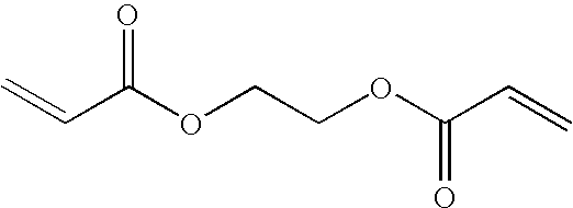
and comprises approximately 15% of bulk material by weight, and may be present in a range of 10% to 50%, inclusive. EGDA also contributes to the modulus and stiffness buildup, as well as facilitates cross-linking of n-HA and IBOA during polymerization of the bulk material. - An initiator component, 2-hydroxy-2-methyl-1-phenyl-propan-1-one, is available from Ciba Specialty Chemicals of Tarrytown, N.Y. under the trade name DAROCUR® 1173, and has the following structure:

and comprises approximately 3% of the bulk material by weight, and may be present in a range of 1% to 5%, inclusive. The initiator is responsive to a broad band of ultra-violet radiation generated by a medium-pressure mercury lamp. In this manner, the initiator facilitates cross-linking and polymerization of the components of the bulk material. The constituent components of COMPOSITION, IBOA, n-HA, EGDA and 2-hydroxy-2-methyl-1-phenyl-propan-1-one form the bulk material of the same. - A surfactant component, R1R2, is a non-ionic surfactant sold by Mason Chemical Company of Arlington Heights, Ill. under the product names MASURF® FS-2000. The surfactant component consists of approximately 2%, by weight, of the bulk material and acts as a release agent of COMPOSITION by facilitating preferential adhesion and release of
contiguous layer 50, once solidified. - The advantages of this patterning process are manifold. For example, the thickness differential between
protrusions 40 andrecessions 38 facilitates formation, insubstrate 42, of a pattern corresponding to the recorded pattern formed incontiguous layer 50. Specifically, the thickness differential between t1 and t2 ofprotrusions 40 andrecession 38, respectively, results in a greater amount of etch time being required before exposing regions ofsubstrate 42 in superimposition withprotrusions 40 compared with the time required for regions ofsubstrate 42 in superimposition withrecession 52 being exposed. For a given etching process, therefore, etching will commence sooner in regions ofsubstrate 42 in superimposition withrecessions 38 than regions in superimposition withprotrusions 40. This facilitates formation of a pattern in substrate corresponding to the aforementioned recorded pattern. By properly selecting the imprinting materials and etch chemistries, the relational dimensions between the differing features of the pattern eventually transferred intosubstrate 42 may be controlled as desired. To that end, it is desired that the etch characteristics of the recorded pattern, for a given etch chemistry, be substantially uniform. - As a result, the characteristics of the imprinting material are important to efficiently
pattern substrate 42 in light of the unique patterning process employed. As mentioned above, the imprinting material is deposited onsubstrate 42 as a plurality of discrete and spaced-apartdroplets 46. The combined volume ofdroplets 46 is such that the imprinting material is distributed appropriately over an area ofsurface 44 where the recorded pattern is to be formed. In this fashion, the total volume of the imprinting material indroplets 46 defines the distance “d”, to be obtained so that the total volume occupied by the imprinting material in the gap defined betweenmold 36 and the portion ofsubstrate 42 in superimposition therewith once the desired distance “d” is reached is substantially equal to the total volume of the imprinting material indroplets 46. To facilitate the deposition process, it is desired that the imprinting material provide rapid and even spreading of the imprinting material indroplets 46 oversurface 44 so that all thicknesses t1 are substantially uniform and all residual thicknesses t2 are substantially uniform. - Referring to
FIGS. 3 and 6 , a problem recognized by the present invention involves varying characteristics of a contiguous layer of imprinting material. Specifically, formed on asubstrate 142 was alayer 100 in the manner discussed above, i.e., except with a non-patterned mold (not shown) having a smooth surface, to spreaddroplets 46. After spreading ofdroplets 46 the imprinting material was exposed for approximately 700 ms to actinic energy having a wavelength of approximate 365 nm a flux of 77 mW/cm2 to solidify the same. After sequentially forming and solidifyingseveral layers 100 employingmold 36, observed werepits 102 over the area oflayers 100 formed later in the sequence.P 102 were found to be a complete absence oflayer 100 in superimposition withportions 104 ofsubstrate 142 and located betweenportions 106 oflayer 100 having a desired thickness. It is believed thatpits 102 result from an uneven surfactant distribution overlayer 100 that prevents the bulk material of COMPOSITION from being in superimposition withregions 104. The difference becomes more pronounced as the number oflayers 100 imprinted. - Referring to
FIGS. 3, 4 and 6, the present invention overcomes these drawbacks by changing the position ofdroplets 46 in pattern 49 on sequential formation of contiguous layers, such ascontiguous layer contiguous layer 100, with the understanding that the same applies tocontiguous layer 50, as well. Specifically, it was found that the quantity of the surfactant component of COMPOSITION varied incontiguous layer 100 over the surface upon which the composition was spread to form solidifiedcontiguous layer 100. Typically, the composition is deposited uponsurface 44 as a plurality of spaced-apartdroplets 46. It was discovered that the surfactant concentration in the air-liquid interface of each droplet varied as the droplet was spread over the surface. This resulted from several factors, including the viscosity differential between the surfactant component of COMPOSITION and the bulk material component of the same and the consumption of the surfactant component by clinging to themold 36 surface in contact with the COMPOSITION. The presented as surfactant depletion regions (SDR) in the area of the contiguous layer proximate to the situs of thedroplets 46,regions 106, and a surfactant rich region (SRR) in areas of the layer located proximate to spaces between the droplets,regions 104. - Referring to
FIGS. 3, 8 and 9, observing that surfactants have an affinity for the region of a liquid proximate to a liquid-air interface it was realized that during formation of a contiguous layer, surfactant molecules underwent redistribution due to the varying size of the liquid-air-interface. Upon deposition ofdroplets 46 onsurface 44, each of thedroplets 46 generates an initial liquid-air interface 120.Surfactant molecules 122 are packed tightly, after a predetermined time, atinterface 120. Asmold 36 interacts withdroplets 46, liquid indroplets 46 moves with respect tosubstrate 42, in direction of the movement shown by arrow 124 forming a series of intermediate patterns, such aspattern 110, beforedroplets 46 merge to formcontiguous layer 100. Asdroplets 46 move the air-liquid interface 120 moves, shown by liquid-air interface 220, which finally becomes ambient-air interface 108, shown inFIG. 7 . This results in the, the spacing betweenadjacent surfactant molecules 122 increasing, shown inFIG. 9 , for the reasons discussed above. As a result, a greater number of surfactant molecules travel from regions of liquids in superimposition with deposition zones ofmold 36, creating SDR regions thereat, and an SRR region in areas of liquid in superimposition with interstices ofmold 36, shown inFIG. 4 . - Referring to
FIGS. 4, 6 , 8 and 9, the presences ofsurfactant molecules 122 incontiguous layer 100 generates a lamella layer 150 onmold 36 after formation of eachcontiguous layer 100. Lamella layer 150 comprises a densely packed fluid composition ofsurfactant molecules 122. The distribution ofsurfactant molecules 122 in lamella layer 150 matches the distribution of surfactant molecules incontiguous layer 100, i.e.SDR regions 102 andSRR region 104. Thus, there is an uneven distribution ofsurfactant molecules 122 in lamella layer 150. On formation of subsequent contiguous layers, the difference in surfactant molecule distribution in lamella layer 150 may become exacerbated, resulting in an increasing probability that voids may be present incontiguous layer 100. To reduce, if not avoid an uneven distribution ofsurfactant molecules 122 inlayers 100 and 150, a subsequent layer formed bymold 36 would be generated by locating deposition zones of the same to be in superimposition with interstices of a previously formedcontiguous layer 100 that includesregions 104, shown more clearly inFIG. 10 . - Referring again to
FIGS. 4, 6 , 8 and 9, in this manner, the existingsurfactant molecule 122 distribution present in lamella 150 may be compensated for, at least in part, by the resultingsurfactant molecule 122 distribution from spreading ofdroplets 46 to formcontiguous layer 100. This is referred to as a droplet pattern shift in which sequential contiguous layers formed from COMPOSITION is generated by shifting the droplets in the pattern for one of the contiguous layers in the sequence compared to the position of the droplets in the pattern employed to form the previous contiguous layer in the sequence. - Referring to
FIG. 10 , it should be understood, however, that it need not be necessary to shift the pattern 49 of droplets so that the entire area ofdroplets 46 are in superimposition with the interstices. Rather, it is within the spirit of the present invention that there may be an overlap betweendroplets 46 of one pattern and droplets 146 of the next patterned form in a sequence. This may be repeated until a pattern is formed corresponding to a subsequent contiguous layer the area of which is entirely within avoid 53 of an initial pattern and, therefore, the interstice. Moreover, it may be desirable to vary the quantity of surfactants in one or more ofdroplets contiguous layer 100, shown inFIG. 6 . - The embodiments of the present invention described above are exemplary. Many changes and modifications may be made to the disclosure recited above while remaining within the scope of the invention. The scope of the invention should not, therefore, be limited by the above description, but instead should be determined with reference to the appended claims along with their full scope of equivalents.
Claims (20)
Priority Applications (1)
| Application Number | Priority Date | Filing Date | Title |
|---|---|---|---|
| US11/608,374 US7981481B2 (en) | 2004-09-23 | 2006-12-08 | Method for controlling distribution of fluid components on a body |
Applications Claiming Priority (2)
| Application Number | Priority Date | Filing Date | Title |
|---|---|---|---|
| US10/948,511 US20060062922A1 (en) | 2004-09-23 | 2004-09-23 | Polymerization technique to attenuate oxygen inhibition of solidification of liquids and composition therefor |
| US11/608,374 US7981481B2 (en) | 2004-09-23 | 2006-12-08 | Method for controlling distribution of fluid components on a body |
Related Parent Applications (1)
| Application Number | Title | Priority Date | Filing Date |
|---|---|---|---|
| US10/948,511 Continuation-In-Part US20060062922A1 (en) | 2004-09-23 | 2004-09-23 | Polymerization technique to attenuate oxygen inhibition of solidification of liquids and composition therefor |
Publications (2)
| Publication Number | Publication Date |
|---|---|
| US20070141271A1 true US20070141271A1 (en) | 2007-06-21 |
| US7981481B2 US7981481B2 (en) | 2011-07-19 |
Family
ID=36074353
Family Applications (3)
| Application Number | Title | Priority Date | Filing Date |
|---|---|---|---|
| US10/948,511 Abandoned US20060062922A1 (en) | 2004-09-23 | 2004-09-23 | Polymerization technique to attenuate oxygen inhibition of solidification of liquids and composition therefor |
| US11/608,374 Active 2027-09-22 US7981481B2 (en) | 2004-09-23 | 2006-12-08 | Method for controlling distribution of fluid components on a body |
| US11/858,687 Active 2024-12-09 US7845931B2 (en) | 2004-09-23 | 2007-09-20 | Polymerization technique to attenuate oxygen inhibition of solidification of liquids and composition therefor |
Family Applications Before (1)
| Application Number | Title | Priority Date | Filing Date |
|---|---|---|---|
| US10/948,511 Abandoned US20060062922A1 (en) | 2004-09-23 | 2004-09-23 | Polymerization technique to attenuate oxygen inhibition of solidification of liquids and composition therefor |
Family Applications After (1)
| Application Number | Title | Priority Date | Filing Date |
|---|---|---|---|
| US11/858,687 Active 2024-12-09 US7845931B2 (en) | 2004-09-23 | 2007-09-20 | Polymerization technique to attenuate oxygen inhibition of solidification of liquids and composition therefor |
Country Status (9)
| Country | Link |
|---|---|
| US (3) | US20060062922A1 (en) |
| EP (2) | EP1796851B1 (en) |
| JP (1) | JP4942657B2 (en) |
| KR (1) | KR101219354B1 (en) |
| CN (1) | CN101022894A (en) |
| AT (1) | ATE486666T1 (en) |
| DE (1) | DE602005024589D1 (en) |
| TW (1) | TWI319349B (en) |
| WO (1) | WO2006036562A2 (en) |
Cited By (29)
| Publication number | Priority date | Publication date | Assignee | Title |
|---|---|---|---|---|
| US20060035029A1 (en) * | 2004-08-16 | 2006-02-16 | Molecular Imprints, Inc. | Method to provide a layer with uniform etch characteristics |
| US20070017631A1 (en) * | 2005-07-22 | 2007-01-25 | Molecular Imprints, Inc. | Method for adhering materials together |
| US20080085465A1 (en) * | 2004-09-23 | 2008-04-10 | Molecular Imprints, Inc. | Polymerization Technique to Attenuate Oxygen Inhibition of Solidification of Liquids and Composition Therefor |
| US20080174046A1 (en) * | 2002-07-11 | 2008-07-24 | Molecular Imprints Inc. | Capillary Imprinting Technique |
| US20080303187A1 (en) * | 2006-12-29 | 2008-12-11 | Molecular Imprints, Inc. | Imprint Fluid Control |
| US20090014917A1 (en) * | 2007-07-10 | 2009-01-15 | Molecular Imprints, Inc. | Drop Pattern Generation for Imprint Lithography |
| US20090115110A1 (en) * | 2007-11-02 | 2009-05-07 | Molecular Imprints, Inc. | Drop Pattern Generation for Imprint Lithography |
| US20090148619A1 (en) * | 2007-12-05 | 2009-06-11 | Molecular Imprints, Inc. | Controlling Thickness of Residual Layer |
| US20090200710A1 (en) * | 2008-02-08 | 2009-08-13 | Molecular Imprints, Inc. | Extrusion reduction in imprint lithography |
| US20090243153A1 (en) * | 2008-04-01 | 2009-10-01 | Molecular Imprints, Inc. | Large Area Roll-To-Roll Imprint Lithography |
| US7670529B2 (en) | 2005-12-08 | 2010-03-02 | Molecular Imprints, Inc. | Method and system for double-sided patterning of substrates |
| US7670530B2 (en) | 2006-01-20 | 2010-03-02 | Molecular Imprints, Inc. | Patterning substrates employing multiple chucks |
| US7691313B2 (en) | 2002-11-13 | 2010-04-06 | Molecular Imprints, Inc. | Method for expelling gas positioned between a substrate and a mold |
| US20100098859A1 (en) * | 2008-10-21 | 2010-04-22 | Molecular Imprints, Inc. | Drop Pattern Generation with Edge Weighting |
| US20100096764A1 (en) * | 2008-10-20 | 2010-04-22 | Molecular Imprints, Inc. | Gas Environment for Imprint Lithography |
| US20100112220A1 (en) * | 2008-11-03 | 2010-05-06 | Molecular Imprints, Inc. | Dispense system set-up and characterization |
| US20100109195A1 (en) * | 2008-11-05 | 2010-05-06 | Molecular Imprints, Inc. | Release agent partition control in imprint lithography |
| US7759407B2 (en) | 2005-07-22 | 2010-07-20 | Molecular Imprints, Inc. | Composition for adhering materials together |
| US20100193994A1 (en) * | 2009-02-04 | 2010-08-05 | Asml Netherlands B.V. | Imprint lithography method and apparatus |
| US7837921B2 (en) | 2004-01-23 | 2010-11-23 | Molecular Imprints, Inc. | Method of providing desirable wetting and release characteristics between a mold and a polymerizable composition |
| US20110215503A1 (en) * | 2004-11-24 | 2011-09-08 | Molecular Imprints, Inc. | Reducing Adhesion between a Conformable Region and a Mold |
| US8142703B2 (en) | 2005-10-05 | 2012-03-27 | Molecular Imprints, Inc. | Imprint lithography method |
| US20120074605A1 (en) * | 2010-09-24 | 2012-03-29 | Kabushiki Kaisha Toshiba | Fine processing method, fine processing apparatus, and recording medium with fine processing program recorded thereon |
| US8152511B2 (en) | 2003-06-17 | 2012-04-10 | Molecular Imprints, Inc. | Composition to reduce adhesion between a conformable region and a mold |
| US8211214B2 (en) | 2003-10-02 | 2012-07-03 | Molecular Imprints, Inc. | Single phase fluid imprint lithography method |
| US8215946B2 (en) | 2006-05-18 | 2012-07-10 | Molecular Imprints, Inc. | Imprint lithography system and method |
| US8586126B2 (en) | 2008-10-21 | 2013-11-19 | Molecular Imprints, Inc. | Robust optimization to generate drop patterns in imprint lithography which are tolerant of variations in drop volume and drop placement |
| US8808808B2 (en) | 2005-07-22 | 2014-08-19 | Molecular Imprints, Inc. | Method for imprint lithography utilizing an adhesion primer layer |
| US20160288404A1 (en) * | 2015-03-31 | 2016-10-06 | Canon Kk | Imprint apparatus, imprint method, and method of manufacturing article |
Families Citing this family (19)
| Publication number | Priority date | Publication date | Assignee | Title |
|---|---|---|---|---|
| US7365103B2 (en) * | 2002-12-12 | 2008-04-29 | Board Of Regents, The University Of Texas System | Compositions for dark-field polymerization and method of using the same for imprint lithography processes |
| US8721952B2 (en) * | 2004-11-16 | 2014-05-13 | International Business Machines Corporation | Pneumatic method and apparatus for nano imprint lithography having a conforming mask |
| US8846195B2 (en) * | 2005-07-22 | 2014-09-30 | Canon Nanotechnologies, Inc. | Ultra-thin polymeric adhesion layer |
| US8012395B2 (en) | 2006-04-18 | 2011-09-06 | Molecular Imprints, Inc. | Template having alignment marks formed of contrast material |
| US20080110557A1 (en) * | 2006-11-15 | 2008-05-15 | Molecular Imprints, Inc. | Methods and Compositions for Providing Preferential Adhesion and Release of Adjacent Surfaces |
| US8945444B2 (en) * | 2007-12-04 | 2015-02-03 | Canon Nanotechnologies, Inc. | High throughput imprint based on contact line motion tracking control |
| US9323143B2 (en) * | 2008-02-05 | 2016-04-26 | Canon Nanotechnologies, Inc. | Controlling template surface composition in nano-imprint lithography |
| US8361546B2 (en) * | 2008-10-30 | 2013-01-29 | Molecular Imprints, Inc. | Facilitating adhesion between substrate and patterned layer |
| CN102438841A (en) | 2009-03-23 | 2012-05-02 | 因特瓦克公司 | A process for optimization of island to trench ratio in patterned media |
| JP5397054B2 (en) * | 2009-07-08 | 2014-01-22 | 大日本印刷株式会社 | Nanoimprint method and nanoimprint apparatus |
| WO2011066450A2 (en) * | 2009-11-24 | 2011-06-03 | Molecular Imprints, Inc. | Adhesion layers in nanoimprint lithography |
| JP6012344B2 (en) * | 2011-10-24 | 2016-10-25 | キヤノン株式会社 | Method for forming film |
| FR2998793B1 (en) | 2012-11-30 | 2014-11-28 | Oreal | COSMETIC COMPOSITION IN THE FORM OF OIL-IN-WATER EMULSION |
| JP5644906B2 (en) * | 2013-07-18 | 2014-12-24 | 大日本印刷株式会社 | Nanoimprint method |
| US9550845B2 (en) | 2014-04-08 | 2017-01-24 | The Board Of Trustees Of The University Of Illinois | Multiple stage curable polymer with controlled transitions |
| CN107075661B (en) * | 2014-09-26 | 2020-03-17 | 韩国机械研究院 | Substrate formed with a plurality of nanogaps and method for preparing the same |
| JP6363473B2 (en) * | 2014-11-17 | 2018-07-25 | 株式会社トクヤマ | Photo-curable composition for imprint, and method for producing resist laminate using the composition |
| JP7397721B2 (en) | 2020-03-06 | 2023-12-13 | キヤノン株式会社 | Determination method, imprint method, imprint device, article manufacturing method and program |
| EP4249524A1 (en) * | 2020-11-19 | 2023-09-27 | Daikin Industries, Ltd. | Fluoropolymer and method for producing same |
Citations (95)
| Publication number | Priority date | Publication date | Assignee | Title |
|---|---|---|---|---|
| US3810874A (en) * | 1969-03-10 | 1974-05-14 | Minnesota Mining & Mfg | Polymers prepared from poly(perfluoro-alkylene oxide) compounds |
| US4271258A (en) * | 1980-06-11 | 1981-06-02 | Tamura Kaken Co., Ltd. | Photopolymerizable ink compositions |
| US4512848A (en) * | 1984-02-06 | 1985-04-23 | Exxon Research And Engineering Co. | Procedure for fabrication of microstructures over large areas using physical replication |
| US4514439A (en) * | 1983-09-16 | 1985-04-30 | Rohm And Haas Company | Dust cover |
| US4517337A (en) * | 1984-02-24 | 1985-05-14 | General Electric Company | Room temperature vulcanizable organopolysiloxane compositions and method for making |
| US4722878A (en) * | 1984-11-09 | 1988-02-02 | Mitsubishi Denki Kabushiki Kaisha | Photomask material |
| US4731155A (en) * | 1987-04-15 | 1988-03-15 | General Electric Company | Process for forming a lithographic mask |
| US4808511A (en) * | 1987-05-19 | 1989-02-28 | International Business Machines Corporation | Vapor phase photoresist silylation process |
| US4826943A (en) * | 1986-07-25 | 1989-05-02 | Oki Electric Industry Co., Ltd. | Negative resist material |
| US4931351A (en) * | 1987-01-12 | 1990-06-05 | Eastman Kodak Company | Bilayer lithographic process |
| US4988274A (en) * | 1987-12-21 | 1991-01-29 | Dresser Industries, Inc. | Method and apparatus for producing an optical element |
| US5108875A (en) * | 1988-07-29 | 1992-04-28 | Shipley Company Inc. | Photoresist pattern fabrication employing chemically amplified metalized material |
| US5110514A (en) * | 1989-05-01 | 1992-05-05 | Soane Technologies, Inc. | Controlled casting of a shrinkable material |
| US5180757A (en) * | 1987-12-16 | 1993-01-19 | Michael Lucey | Photopolymerizable compositions used in electronics |
| US5204381A (en) * | 1990-02-13 | 1993-04-20 | The United States Of America As Represented By The United States Department Of Energy | Hybrid sol-gel optical materials |
| US5206983A (en) * | 1991-06-24 | 1993-05-04 | Wisconsin Alumni Research Foundation | Method of manufacturing micromechanical devices |
| US5298556A (en) * | 1992-07-21 | 1994-03-29 | Tse Industries, Inc. | Mold release composition and method coating a mold core |
| US5302627A (en) * | 1990-12-28 | 1994-04-12 | Dow Corning Corporation | Method of indicating a cure point for ultraviolet radiation curing compositions by color change |
| US5314731A (en) * | 1991-05-17 | 1994-05-24 | Asahi Glass Company Ltd. | Surface-treated substrate |
| US5318870A (en) * | 1989-10-18 | 1994-06-07 | Massachusetts Institute Of Technology | Method of patterning a phenolic polymer film without photoactive additive through exposure to high energy radiation below 225 nm with subsequent organometallic treatment and the associated imaged article |
| US5395954A (en) * | 1992-07-20 | 1995-03-07 | Societe Des Ceramiques Techniques | Organic-inorganic polycondensate and a method of obtaining the same |
| US5417802A (en) * | 1994-03-18 | 1995-05-23 | At&T Corp. | Integrated circuit manufacturing |
| US5425848A (en) * | 1993-03-16 | 1995-06-20 | U.S. Philips Corporation | Method of providing a patterned relief of cured photoresist on a flat substrate surface and device for carrying out such a method |
| US5480047A (en) * | 1993-06-04 | 1996-01-02 | Sharp Kabushiki Kaisha | Method for forming a fine resist pattern |
| US5482768A (en) * | 1993-05-14 | 1996-01-09 | Asahi Glass Company Ltd. | Surface-treated substrate and process for its production |
| US5512131A (en) * | 1993-10-04 | 1996-04-30 | President And Fellows Of Harvard College | Formation of microstamped patterns on surfaces and derivative articles |
| US5523878A (en) * | 1994-06-30 | 1996-06-04 | Texas Instruments Incorporated | Self-assembled monolayer coating for micro-mechanical devices |
| US5527662A (en) * | 1990-05-24 | 1996-06-18 | Matsushita Electric Industrial Co., Ltd. | Process for forming fine pattern |
| US5594042A (en) * | 1993-05-18 | 1997-01-14 | Dow Corning Corporation | Radiation curable compositions containing vinyl ether functional polyorganosiloxanes |
| US5601641A (en) * | 1992-07-21 | 1997-02-11 | Tse Industries, Inc. | Mold release composition with polybutadiene and method of coating a mold core |
| US5629128A (en) * | 1994-10-31 | 1997-05-13 | Fuji Photo Film Co., Ltd. | Positive photoresist composition |
| US5629095A (en) * | 1993-05-18 | 1997-05-13 | Dow Corning Corporation | Radiation curable compositions containing vinyl ether functional polysiloxanes and methods for the preparation |
| US5723242A (en) * | 1996-03-28 | 1998-03-03 | Minnesota Mining And Manufacturing Company | Perfluoroether release coatings for organic photoreceptors |
| US5725788A (en) * | 1996-03-04 | 1998-03-10 | Motorola | Apparatus and method for patterning a surface |
| US5772905A (en) * | 1995-11-15 | 1998-06-30 | Regents Of The University Of Minnesota | Nanoimprint lithography |
| US5888650A (en) * | 1996-06-03 | 1999-03-30 | Minnesota Mining And Manufacturing Company | Temperature-responsive adhesive article |
| US5895263A (en) * | 1996-12-19 | 1999-04-20 | International Business Machines Corporation | Process for manufacture of integrated circuit device |
| US6046056A (en) * | 1996-06-28 | 2000-04-04 | Caliper Technologies Corporation | High throughput screening assay systems in microscale fluidic devices |
| US6063888A (en) * | 1996-04-09 | 2000-05-16 | Dsm N.V. | Liquid curable resin composition |
| US6066269A (en) * | 1995-03-30 | 2000-05-23 | Drexel University | Electroactive inorganic hybrid materials |
| US6074827A (en) * | 1996-07-30 | 2000-06-13 | Aclara Biosciences, Inc. | Microfluidic method for nucleic acid purification and processing |
| US6174931B1 (en) * | 1991-02-28 | 2001-01-16 | 3M Innovative Properties Company | Multi-stage irradiation process for production of acrylic based compositions and compositions made thereby |
| US6190929B1 (en) * | 1999-07-23 | 2001-02-20 | Micron Technology, Inc. | Methods of forming semiconductor devices and methods of forming field emission displays |
| US6200736B1 (en) * | 1998-04-15 | 2001-03-13 | Etec Systems, Inc. | Photoresist developer and method |
| US6204343B1 (en) * | 1996-12-11 | 2001-03-20 | 3M Innovative Properties Company | Room temperature curable resin |
| US6218316B1 (en) * | 1998-10-22 | 2001-04-17 | Micron Technology, Inc. | Planarization of non-planar surfaces in device fabrication |
| US6335149B1 (en) * | 1997-04-08 | 2002-01-01 | Corning Incorporated | High performance acrylate materials for optical interconnects |
| US6334960B1 (en) * | 1999-03-11 | 2002-01-01 | Board Of Regents, The University Of Texas System | Step and flash imprint lithography |
| US6342097B1 (en) * | 1999-04-23 | 2002-01-29 | Sdc Coatings, Inc. | Composition for providing an abrasion resistant coating on a substrate with a matched refractive index and controlled tintability |
| US6344105B1 (en) * | 1999-06-30 | 2002-02-05 | Lam Research Corporation | Techniques for improving etch rate uniformity |
| US6348999B1 (en) * | 1995-05-10 | 2002-02-19 | Epigem Limited | Micro relief element and preparation thereof |
| US6355198B1 (en) * | 1996-03-15 | 2002-03-12 | President And Fellows Of Harvard College | Method of forming articles including waveguides via capillary micromolding and microtransfer molding |
| US20020042027A1 (en) * | 1998-10-09 | 2002-04-11 | Chou Stephen Y. | Microscale patterning and articles formed thereby |
| US6391217B2 (en) * | 1999-12-23 | 2002-05-21 | University Of Massachusetts | Methods and apparatus for forming submicron patterns on films |
| US6399406B2 (en) * | 2000-06-19 | 2002-06-04 | International Business Machines Corporation | Encapsulated MEMS band-pass filter for integrated circuits and method of fabrication thereof |
| US6503914B1 (en) * | 2000-10-23 | 2003-01-07 | Board Of Regents, The University Of Texas System | Thienopyrimidine-based inhibitors of the Src family |
| US6518189B1 (en) * | 1995-11-15 | 2003-02-11 | Regents Of The University Of Minnesota | Method and apparatus for high density nanostructures |
| US6517995B1 (en) * | 1999-09-14 | 2003-02-11 | Massachusetts Institute Of Technology | Fabrication of finely featured devices by liquid embossing |
| US6517977B2 (en) * | 2001-03-28 | 2003-02-11 | Motorola, Inc. | Lithographic template and method of formation and use |
| US6518168B1 (en) * | 1995-08-18 | 2003-02-11 | President And Fellows Of Harvard College | Self-assembled monolayer directed patterning of surfaces |
| US20030034329A1 (en) * | 1998-06-30 | 2003-02-20 | Chou Stephen Y. | Lithographic method for molding pattern with nanoscale depth |
| US20030054115A1 (en) * | 2001-09-14 | 2003-03-20 | Ralph Albano | Ultraviolet curing process for porous low-K materials |
| US6541356B2 (en) * | 2001-05-21 | 2003-04-01 | International Business Machines Corporation | Ultimate SIMOX |
| US20030062334A1 (en) * | 2001-09-25 | 2003-04-03 | Lee Hong Hie | Method for forming a micro-pattern on a substrate by using capillary force |
| US6544594B2 (en) * | 1999-09-10 | 2003-04-08 | Nano-Tex, Llc | Water-repellent and soil-resistant finish for textiles |
| US20030080471A1 (en) * | 2001-10-29 | 2003-05-01 | Chou Stephen Y. | Lithographic method for molding pattern with nanoscale features |
| US6565776B1 (en) * | 1999-06-11 | 2003-05-20 | Bausch & Lomb Incorporated | Lens molds with protective coatings for production of contact lenses and other ophthalmic products |
| US6580172B2 (en) * | 2001-03-02 | 2003-06-17 | Motorola, Inc. | Lithographic template and method of formation and use |
| US6583248B1 (en) * | 1997-01-06 | 2003-06-24 | American Dental Association Health Foundation | Polymerizable cyclodextrin derivatives |
| US6696157B1 (en) * | 2000-03-05 | 2004-02-24 | 3M Innovative Properties Company | Diamond-like glass thin films |
| US6696220B2 (en) * | 2000-10-12 | 2004-02-24 | Board Of Regents, The University Of Texas System | Template for room temperature, low pressure micro-and nano-imprint lithography |
| US20040046288A1 (en) * | 2000-07-18 | 2004-03-11 | Chou Stephen Y. | Laset assisted direct imprint lithography |
| US20040066201A1 (en) * | 1999-04-29 | 2004-04-08 | Ennis Michael G. | Arrangements to detect and respond to disturbances in electrical power systems |
| US20040065252A1 (en) * | 2002-10-04 | 2004-04-08 | Sreenivasan Sidlgata V. | Method of forming a layer on a substrate to facilitate fabrication of metrology standards |
| US6721529B2 (en) * | 2001-09-21 | 2004-04-13 | Nexpress Solutions Llc | Release agent donor member having fluorocarbon thermoplastic random copolymer overcoat |
| US6737489B2 (en) * | 2001-05-21 | 2004-05-18 | 3M Innovative Properties Company | Polymers containing perfluorovinyl ethers and applications for such polymers |
| US20040110856A1 (en) * | 2002-12-04 | 2004-06-10 | Young Jung Gun | Polymer solution for nanoimprint lithography to reduce imprint temperature and pressure |
| US20040112862A1 (en) * | 2002-12-12 | 2004-06-17 | Molecular Imprints, Inc. | Planarization composition and method of patterning a substrate using the same |
| US6849558B2 (en) * | 2002-05-22 | 2005-02-01 | The Board Of Trustees Of The Leland Stanford Junior University | Replication and transfer of microstructures and nanostructures |
| US20050037143A1 (en) * | 2000-07-18 | 2005-02-17 | Chou Stephen Y. | Imprint lithography with improved monitoring and control and apparatus therefor |
| US20050084804A1 (en) * | 2003-10-16 | 2005-04-21 | Molecular Imprints, Inc. | Low surface energy templates |
| US20050113484A1 (en) * | 1997-05-23 | 2005-05-26 | Deco Patents, Inc. | Method and compositions for decorating glass |
| US6900881B2 (en) * | 2002-07-11 | 2005-05-31 | Molecular Imprints, Inc. | Step and repeat imprint lithography systems |
| US20060036051A1 (en) * | 2004-08-16 | 2006-02-16 | Molecular Imprints, Inc. | Composition to provide a layer with uniform etch characteristics |
| US20060035029A1 (en) * | 2004-08-16 | 2006-02-16 | Molecular Imprints, Inc. | Method to provide a layer with uniform etch characteristics |
| US20060062867A1 (en) * | 2002-07-11 | 2006-03-23 | Molecular Imprints, Inc. | Formation of discontinuous films during an imprint lithography process |
| US20060062922A1 (en) * | 2004-09-23 | 2006-03-23 | Molecular Imprints, Inc. | Polymerization technique to attenuate oxygen inhibition of solidification of liquids and composition therefor |
| US20060076717A1 (en) * | 2002-07-11 | 2006-04-13 | Molecular Imprints, Inc. | Step and repeat imprint lithography processes |
| US20060081557A1 (en) * | 2004-10-18 | 2006-04-20 | Molecular Imprints, Inc. | Low-k dielectric functional imprinting materials |
| US7037639B2 (en) * | 2002-05-01 | 2006-05-02 | Molecular Imprints, Inc. | Methods of manufacturing a lithography template |
| US20060108710A1 (en) * | 2004-11-24 | 2006-05-25 | Molecular Imprints, Inc. | Method to reduce adhesion between a conformable region and a mold |
| US7157036B2 (en) * | 2003-06-17 | 2007-01-02 | Molecular Imprints, Inc | Method to reduce adhesion between a conformable region and a pattern of a mold |
| US20070017631A1 (en) * | 2005-07-22 | 2007-01-25 | Molecular Imprints, Inc. | Method for adhering materials together |
| US7179079B2 (en) * | 2002-07-08 | 2007-02-20 | Molecular Imprints, Inc. | Conforming template for patterning liquids disposed on substrates |
| US7360851B1 (en) * | 2006-02-15 | 2008-04-22 | Kla-Tencor Technologies Corporation | Automated pattern recognition of imprint technology |
Family Cites Families (135)
| Publication number | Priority date | Publication date | Assignee | Title |
|---|---|---|---|---|
| DE1720535A1 (en) | 1967-02-23 | 1971-07-08 | Dow Chemical Co | Polymerization of acrylic monomers |
| US3844916A (en) * | 1972-09-18 | 1974-10-29 | Desoto Inc | Radiation curable non-gelled michael addition reaction products |
| US3919351A (en) | 1973-08-29 | 1975-11-11 | Ppg Industries Inc | Composition useful in making extensible films |
| US4118235A (en) * | 1975-09-18 | 1978-10-03 | Daikin Kogyo Co., Ltd. | Mold release agent |
| US4058656A (en) * | 1976-04-05 | 1977-11-15 | Ici United States Inc. | Free radical polymerization process employing substituted amino acetic acid derivatives |
| US4617238A (en) | 1982-04-01 | 1986-10-14 | General Electric Company | Vinyloxy-functional organopolysiloxane compositions |
| US4544572A (en) | 1982-09-07 | 1985-10-01 | Minnesota Mining And Manufacturing Company | Coated ophthalmic lenses and method for coating the same |
| DE3345103A1 (en) * | 1983-12-13 | 1985-06-13 | Bayer Ag, 5090 Leverkusen | NEW AMINES, METHOD FOR THE PRODUCTION THEREOF AND THEIR USE IN RADICALLY POLYMERIZABLE MEASURES |
| US4552833A (en) | 1984-05-14 | 1985-11-12 | International Business Machines Corporation | Radiation sensitive and oxygen plasma developable resist |
| US4614667A (en) | 1984-05-21 | 1986-09-30 | Minnesota Mining And Manufacturing Company | Composite low surface energy liner of perfluoropolyether |
| DE3583707D1 (en) * | 1984-06-26 | 1991-09-12 | Asahi Glass Co Ltd | TRANSPARENT HEAVY DIRTING ITEM WITH LOW REFLECTION. |
| US4707432A (en) * | 1985-09-23 | 1987-11-17 | Ciba-Geigy Corporation | Ferrocenium/alpha-cleavage photoinitiator systems for free radical polymerizable compositions |
| FR2604553A1 (en) | 1986-09-29 | 1988-04-01 | Rhone Poulenc Chimie | RIGID POLYMER SUBSTRATE FOR OPTICAL DISC AND OPTICAL DISCS OBTAINED FROM THE SUBSTRATE |
| US5028366A (en) * | 1988-01-12 | 1991-07-02 | Air Products And Chemicals, Inc. | Water based mold release compositions for making molded polyurethane foam |
| US5439766A (en) * | 1988-12-30 | 1995-08-08 | International Business Machines Corporation | Composition for photo imaging |
| US5169494A (en) | 1989-03-27 | 1992-12-08 | Matsushita Electric Industrial Co., Ltd. | Fine pattern forming method |
| JP3001607B2 (en) * | 1989-04-24 | 2000-01-24 | シーメンス、アクチエンゲゼルシヤフト | Dimensionally stable structure transfer method in two-layer method |
| US5028511A (en) | 1989-05-30 | 1991-07-02 | E. I. Du Pont De Nemours And Company | Process for preparing a precolored image using photosensitive reproduction element containing a photorelease layer |
| US5170182A (en) | 1990-08-23 | 1992-12-08 | Management Graphics, Inc. | Apparatus and method for registering an image on a recording medium |
| DE4029912A1 (en) | 1990-09-21 | 1992-03-26 | Philips Patentverwaltung | METHOD FOR FORMING AT LEAST ONE TRENCH IN A SUBSTRATE LAYER |
| US5170192A (en) | 1990-11-29 | 1992-12-08 | Pilkington Visioncare, Inc. | Oxygen permeable bifocal contact lenses and their manufacture |
| JPH0538797A (en) * | 1991-07-15 | 1993-02-19 | Sekisui Chem Co Ltd | Manufacture of coated material and sheet for coating |
| US5242711A (en) | 1991-08-16 | 1993-09-07 | Rockwell International Corp. | Nucleation control of diamond films by microlithographic patterning |
| DE4228853C2 (en) | 1991-09-18 | 1993-10-21 | Schott Glaswerke | Optical waveguide with a planar or only slightly curved substrate and method for its preparation and use of such |
| JPH0580530A (en) | 1991-09-24 | 1993-04-02 | Hitachi Ltd | Production of thin film pattern |
| US5331020A (en) * | 1991-11-14 | 1994-07-19 | Dow Corning Limited | Organosilicon compounds and compositions containing them |
| JP3123195B2 (en) * | 1992-04-15 | 2001-01-09 | ミノルタ株式会社 | Inkjet recording liquid |
| US5545367A (en) * | 1992-04-15 | 1996-08-13 | Soane Technologies, Inc. | Rapid prototype three dimensional stereolithography |
| US5389696A (en) | 1993-09-17 | 1995-02-14 | Miles Inc. | Process for the production of molded products using internal mold release agents |
| US5776748A (en) * | 1993-10-04 | 1998-07-07 | President And Fellows Of Harvard College | Method of formation of microstamped patterns on plates for adhesion of cells and other biological materials, devices and uses therefor |
| US6776094B1 (en) * | 1993-10-04 | 2004-08-17 | President & Fellows Of Harvard College | Kit For Microcontact Printing |
| US5462700A (en) | 1993-11-08 | 1995-10-31 | Alliedsignal Inc. | Process for making an array of tapered photopolymerized waveguides |
| JPH07238106A (en) * | 1994-03-02 | 1995-09-12 | Japan Synthetic Rubber Co Ltd | Photocurable composition for forming three-dimensional molding and method of accelerating photocuring |
| US5542978A (en) | 1994-06-10 | 1996-08-06 | Johnson & Johnson Vision Products, Inc. | Apparatus for applying a surfactant to mold surfaces |
| US5837314A (en) | 1994-06-10 | 1998-11-17 | Johnson & Johnson Vision Products, Inc. | Method and apparatus for applying a surfactant to mold surfaces |
| US5459198A (en) | 1994-07-29 | 1995-10-17 | E. I. Du Pont De Nemours And Company | Fluoroinfused composites, articles of manufacture formed therefrom, and processes for the preparation thereof |
| US5849209A (en) | 1995-03-31 | 1998-12-15 | Johnson & Johnson Vision Products, Inc. | Mold material made with additives |
| US5820769A (en) | 1995-05-24 | 1998-10-13 | Regents Of The University Of Minnesota | Method for making magnetic storage having discrete elements with quantized magnetic moments |
| US5849222A (en) | 1995-09-29 | 1998-12-15 | Johnson & Johnson Vision Products, Inc. | Method for reducing lens hole defects in production of contact lens blanks |
| US6468642B1 (en) | 1995-10-03 | 2002-10-22 | N.V. Bekaert S.A. | Fluorine-doped diamond-like coatings |
| US7758794B2 (en) * | 2001-10-29 | 2010-07-20 | Princeton University | Method of making an article comprising nanoscale patterns with reduced edge roughness |
| US6482742B1 (en) | 2000-07-18 | 2002-11-19 | Stephen Y. Chou | Fluid pressure imprint lithography |
| US20040137734A1 (en) * | 1995-11-15 | 2004-07-15 | Princeton University | Compositions and processes for nanoimprinting |
| US20040036201A1 (en) * | 2000-07-18 | 2004-02-26 | Princeton University | Methods and apparatus of field-induced pressure imprint lithography |
| US5684066A (en) * | 1995-12-04 | 1997-11-04 | H.B. Fuller Licensing & Financing, Inc. | Protective coatings having enhanced properties |
| US5669303A (en) | 1996-03-04 | 1997-09-23 | Motorola | Apparatus and method for stamping a surface |
| US5948470A (en) | 1997-04-28 | 1999-09-07 | Harrison; Christopher | Method of nanoscale patterning and products made thereby |
| US6132632A (en) | 1997-09-11 | 2000-10-17 | International Business Machines Corporation | Method and apparatus for achieving etch rate uniformity in a reactive ion etcher |
| US6475704B1 (en) | 1997-09-12 | 2002-11-05 | Canon Kabushiki Kaisha | Method for forming fine structure |
| US6117708A (en) | 1998-02-05 | 2000-09-12 | Micron Technology, Inc. | Use of residual organic compounds to facilitate gate break on a carrier substrate for a semiconductor device |
| US6114404A (en) | 1998-03-23 | 2000-09-05 | Corning Incorporated | Radiation curable ink compositions and flat panel color filters made using same |
| JP3931936B2 (en) * | 1998-05-11 | 2007-06-20 | セイコーエプソン株式会社 | Microlens array substrate, method for manufacturing the same, and display device |
| JP3780700B2 (en) | 1998-05-26 | 2006-05-31 | セイコーエプソン株式会社 | Pattern forming method, pattern forming apparatus, pattern forming plate, pattern forming plate manufacturing method, color filter manufacturing method, conductive film manufacturing method, and liquid crystal panel manufacturing method |
| DE19828969A1 (en) | 1998-06-29 | 1999-12-30 | Siemens Ag | Manufacturing integrated semiconductor components |
| US6523803B1 (en) | 1998-09-03 | 2003-02-25 | Micron Technology, Inc. | Mold apparatus used during semiconductor device fabrication |
| US6261469B1 (en) * | 1998-10-13 | 2001-07-17 | Honeywell International Inc. | Three dimensionally periodic structural assemblies on nanometer and longer scales |
| US6274294B1 (en) | 1999-02-03 | 2001-08-14 | Electroformed Stents, Inc. | Cylindrical photolithography exposure process and apparatus |
| US6238798B1 (en) | 1999-02-22 | 2001-05-29 | 3M Innovative Properties Company | Ceramer composition and composite comprising free radically curable fluorochemical component |
| JP4789329B2 (en) * | 2000-04-03 | 2011-10-12 | Jsr株式会社 | Double layer film |
| US6306557B1 (en) * | 2000-04-20 | 2001-10-23 | Industrial Technology Research Foundation | Process for preparing water dispersible negative-type photosensitive compositions |
| KR20010098809A (en) | 2000-04-25 | 2001-11-08 | 마쯔모또 에이찌 | Radiation sensitive resin composition for forming barrier ribs for an EL display element, barrier rib and EL display element |
| US6774183B1 (en) | 2000-04-27 | 2004-08-10 | Bostik, Inc. | Copolyesters having improved retained adhesion |
| EP2264523A3 (en) | 2000-07-16 | 2011-11-30 | Board Of Regents, The University Of Texas System | A method of forming a pattern on a substrate in imprint lithographic processes |
| JP4740518B2 (en) | 2000-07-17 | 2011-08-03 | ボード・オブ・リージエンツ,ザ・ユニバーシテイ・オブ・テキサス・システム | Automated liquid dispensing method and system for transfer lithography process |
| US7635262B2 (en) * | 2000-07-18 | 2009-12-22 | Princeton University | Lithographic apparatus for fluid pressure imprint lithography |
| US6326627B1 (en) | 2000-08-02 | 2001-12-04 | Archimedes Technology Group, Inc. | Mass filtering sputtered ion source |
| US6531407B1 (en) * | 2000-08-31 | 2003-03-11 | Micron Technology, Inc. | Method, structure and process flow to reduce line-line capacitance with low-K material |
| US6448301B1 (en) | 2000-09-08 | 2002-09-10 | 3M Innovative Properties Company | Crosslinkable polymeric compositions and use thereof |
| GB0101070D0 (en) * | 2001-01-16 | 2001-02-28 | Reddiplex Group Plc | Display stands |
| US6664026B2 (en) | 2001-03-22 | 2003-12-16 | International Business Machines Corporation | Method of manufacturing high aspect ratio photolithographic features |
| US6736857B2 (en) | 2001-05-25 | 2004-05-18 | 3M Innovative Properties Company | Method for imparting soil and stain resistance to carpet |
| US7141188B2 (en) | 2001-05-30 | 2006-11-28 | Honeywell International Inc. | Organic compositions |
| EP1417474B1 (en) | 2001-07-25 | 2021-12-29 | The Trustees Of Princeton University | Nanochannel arrays and their preparation and use for high throughput macromolecular analysis |
| JP2003161802A (en) * | 2001-09-14 | 2003-06-06 | Dainippon Printing Co Ltd | Light-curing resin composite, sheet, transfer foil, minute project and recessed pattern forming method and optical component |
| US6790905B2 (en) | 2001-10-09 | 2004-09-14 | E. I. Du Pont De Nemours And Company | Highly repellent carpet protectants |
| US6716767B2 (en) * | 2001-10-31 | 2004-04-06 | Brewer Science, Inc. | Contact planarization materials that generate no volatile byproducts or residue during curing |
| JP2005516406A (en) | 2001-11-07 | 2005-06-02 | ダウ グローバル テクノロジーズ インコーポレイティド | Planarized microelectronic substrate |
| US6649272B2 (en) | 2001-11-08 | 2003-11-18 | 3M Innovative Properties Company | Coating composition comprising fluorochemical polyether silane polycondensate and use thereof |
| US6605849B1 (en) | 2002-02-14 | 2003-08-12 | Symmetricom, Inc. | MEMS analog frequency divider |
| KR100949343B1 (en) * | 2002-02-19 | 2010-03-26 | 닛산 가가쿠 고교 가부시키 가이샤 | Composition for forming anti-reflection coating |
| TWI339680B (en) | 2002-02-19 | 2011-04-01 | Kanto Kagaku | Washing liquid composition for semiconductor substrate |
| JP2004002702A (en) | 2002-02-28 | 2004-01-08 | Merck Patent Gmbh | Prepolymer material, polymer material, imprinting process and its use |
| US20030235787A1 (en) | 2002-06-24 | 2003-12-25 | Watts Michael P.C. | Low viscosity high resolution patterning material |
| US6926929B2 (en) | 2002-07-09 | 2005-08-09 | Molecular Imprints, Inc. | System and method for dispensing liquids |
| US6908861B2 (en) * | 2002-07-11 | 2005-06-21 | Molecular Imprints, Inc. | Method for imprint lithography using an electric field |
| US7019819B2 (en) | 2002-11-13 | 2006-03-28 | Molecular Imprints, Inc. | Chucking system for modulating shapes of substrates |
| US7442336B2 (en) | 2003-08-21 | 2008-10-28 | Molecular Imprints, Inc. | Capillary imprinting technique |
| AU2003256654A1 (en) | 2002-07-23 | 2004-02-09 | Pennzoil-Quaker State Company | Hydrophobic surface treatment composition and method of making and using same |
| JP2006516065A (en) | 2002-08-01 | 2006-06-15 | モレキュラー・インプリンツ・インコーポレーテッド | Scatter measurement alignment for imprint lithography |
| US7070405B2 (en) * | 2002-08-01 | 2006-07-04 | Molecular Imprints, Inc. | Alignment systems for imprint lithography |
| US6916584B2 (en) * | 2002-08-01 | 2005-07-12 | Molecular Imprints, Inc. | Alignment methods for imprint lithography |
| US7027156B2 (en) * | 2002-08-01 | 2006-04-11 | Molecular Imprints, Inc. | Scatterometry alignment for imprint lithography |
| US7071088B2 (en) | 2002-08-23 | 2006-07-04 | Molecular Imprints, Inc. | Method for fabricating bulbous-shaped vias |
| US6936194B2 (en) * | 2002-09-05 | 2005-08-30 | Molecular Imprints, Inc. | Functional patterning material for imprint lithography processes |
| US8349241B2 (en) | 2002-10-04 | 2013-01-08 | Molecular Imprints, Inc. | Method to arrange features on a substrate to replicate features having minimal dimensional variability |
| US6980282B2 (en) | 2002-12-11 | 2005-12-27 | Molecular Imprints, Inc. | Method for modulating shapes of substrates |
| US6871558B2 (en) | 2002-12-12 | 2005-03-29 | Molecular Imprints, Inc. | Method for determining characteristics of substrate employing fluid geometries |
| US7365103B2 (en) * | 2002-12-12 | 2008-04-29 | Board Of Regents, The University Of Texas System | Compositions for dark-field polymerization and method of using the same for imprint lithography processes |
| CN1519260A (en) | 2003-01-20 | 2004-08-11 | 上海华谊(集团)公司 | Method of controllable free radical polymerization by using sulfid of amino thiocarbonyl as chain transfer agent |
| TWI230832B (en) * | 2003-01-24 | 2005-04-11 | Sipix Imaging Inc | Novel adhesive and sealing layers for electrophoretic displays |
| US7452574B2 (en) | 2003-02-27 | 2008-11-18 | Molecular Imprints, Inc. | Method to reduce adhesion between a polymerizable layer and a substrate employing a fluorine-containing layer |
| US6830819B2 (en) | 2003-03-18 | 2004-12-14 | Xerox Corporation | Fluorosilicone release agent for fluoroelastomer fuser members |
| US7122079B2 (en) | 2004-02-27 | 2006-10-17 | Molecular Imprints, Inc. | Composition for an etching mask comprising a silicon-containing material |
| JP4651390B2 (en) | 2003-03-27 | 2011-03-16 | コリア・インスティテュート・オブ・マシナリー・アンド・マテリアルズ | UV nanoimprint lithography using multiple relief element stamps |
| TWI228638B (en) | 2003-06-10 | 2005-03-01 | Ind Tech Res Inst | Method for and apparatus for bonding patterned imprint to a substrate by adhering means |
| US20050160934A1 (en) | 2004-01-23 | 2005-07-28 | Molecular Imprints, Inc. | Materials and methods for imprint lithography |
| US8211214B2 (en) | 2003-10-02 | 2012-07-03 | Molecular Imprints, Inc. | Single phase fluid imprint lithography method |
| US7090716B2 (en) | 2003-10-02 | 2006-08-15 | Molecular Imprints, Inc. | Single phase fluid imprint lithography method |
| US7122482B2 (en) * | 2003-10-27 | 2006-10-17 | Molecular Imprints, Inc. | Methods for fabricating patterned features utilizing imprint lithography |
| US20050098534A1 (en) * | 2003-11-12 | 2005-05-12 | Molecular Imprints, Inc. | Formation of conductive templates employing indium tin oxide |
| US20050106321A1 (en) | 2003-11-14 | 2005-05-19 | Molecular Imprints, Inc. | Dispense geometery to achieve high-speed filling and throughput |
| US8076386B2 (en) * | 2004-02-23 | 2011-12-13 | Molecular Imprints, Inc. | Materials for imprint lithography |
| US20050189676A1 (en) | 2004-02-27 | 2005-09-01 | Molecular Imprints, Inc. | Full-wafer or large area imprinting with multiple separated sub-fields for high throughput lithography |
| US20050276919A1 (en) | 2004-06-01 | 2005-12-15 | Molecular Imprints, Inc. | Method for dispensing a fluid on a substrate |
| CN100570445C (en) | 2004-06-03 | 2009-12-16 | 分子制模股份有限公司 | Be used for fluid distribution and drop-on-demand distribution that nanometer scale is made |
| US20050270516A1 (en) | 2004-06-03 | 2005-12-08 | Molecular Imprints, Inc. | System for magnification and distortion correction during nano-scale manufacturing |
| US20070228593A1 (en) | 2006-04-03 | 2007-10-04 | Molecular Imprints, Inc. | Residual Layer Thickness Measurement and Correction |
| US7309225B2 (en) * | 2004-08-13 | 2007-12-18 | Molecular Imprints, Inc. | Moat system for an imprint lithography template |
| JP4904742B2 (en) * | 2004-09-16 | 2012-03-28 | 旭硝子株式会社 | Pattern forming method and article having pattern |
| US7547504B2 (en) | 2004-09-21 | 2009-06-16 | Molecular Imprints, Inc. | Pattern reversal employing thick residual layers |
| US7244386B2 (en) | 2004-09-27 | 2007-07-17 | Molecular Imprints, Inc. | Method of compensating for a volumetric shrinkage of a material disposed upon a substrate to form a substantially planar structure therefrom |
| WO2006060758A2 (en) | 2004-12-01 | 2006-06-08 | Molecular Imprints, Inc. | Methods of exposure for the purpose of thermal management for imprint lithography processes |
| US7281919B2 (en) | 2004-12-07 | 2007-10-16 | Molecular Imprints, Inc. | System for controlling a volume of material on a mold |
| US20060145398A1 (en) | 2004-12-30 | 2006-07-06 | Board Of Regents, The University Of Texas System | Release layer comprising diamond-like carbon (DLC) or doped DLC with tunable composition for imprint lithography templates and contact masks |
| US20060177532A1 (en) | 2005-02-04 | 2006-08-10 | Molecular Imprints, Inc. | Imprint lithography method to control extrusion of a liquid from a desired region on a substrate |
| US20060177535A1 (en) | 2005-02-04 | 2006-08-10 | Molecular Imprints, Inc. | Imprint lithography template to facilitate control of liquid movement |
| US20070228608A1 (en) | 2006-04-03 | 2007-10-04 | Molecular Imprints, Inc. | Preserving Filled Features when Vacuum Wiping |
| US7759407B2 (en) * | 2005-07-22 | 2010-07-20 | Molecular Imprints, Inc. | Composition for adhering materials together |
| US7316554B2 (en) | 2005-09-21 | 2008-01-08 | Molecular Imprints, Inc. | System to control an atmosphere between a body and a substrate |
| US7906058B2 (en) | 2005-12-01 | 2011-03-15 | Molecular Imprints, Inc. | Bifurcated contact printing technique |
| US7670530B2 (en) | 2006-01-20 | 2010-03-02 | Molecular Imprints, Inc. | Patterning substrates employing multiple chucks |
| WO2007067488A2 (en) | 2005-12-08 | 2007-06-14 | Molecular Imprints, Inc. | Method and system for double-sided patterning of substrates |
| JP5306989B2 (en) | 2006-04-03 | 2013-10-02 | モレキュラー・インプリンツ・インコーポレーテッド | Method for simultaneously patterning a substrate having a plurality of fields and alignment marks |
| US7462028B2 (en) | 2006-04-03 | 2008-12-09 | Molecular Imprints, Inc. | Partial vacuum environment imprinting |
| US20080303187A1 (en) | 2006-12-29 | 2008-12-11 | Molecular Imprints, Inc. | Imprint Fluid Control |
-
2004
- 2004-09-23 US US10/948,511 patent/US20060062922A1/en not_active Abandoned
-
2005
- 2005-09-13 EP EP05815380A patent/EP1796851B1/en active Active
- 2005-09-13 EP EP10189201A patent/EP2272594A1/en not_active Withdrawn
- 2005-09-13 JP JP2007532433A patent/JP4942657B2/en active Active
- 2005-09-13 WO PCT/US2005/032804 patent/WO2006036562A2/en active Application Filing
- 2005-09-13 KR KR1020077006501A patent/KR101219354B1/en active IP Right Grant
- 2005-09-13 CN CNA2005800314031A patent/CN101022894A/en active Pending
- 2005-09-13 DE DE602005024589T patent/DE602005024589D1/en active Active
- 2005-09-13 AT AT05815380T patent/ATE486666T1/en active
- 2005-09-19 TW TW094132300A patent/TWI319349B/en not_active IP Right Cessation
-
2006
- 2006-12-08 US US11/608,374 patent/US7981481B2/en active Active
-
2007
- 2007-09-20 US US11/858,687 patent/US7845931B2/en active Active
Patent Citations (99)
| Publication number | Priority date | Publication date | Assignee | Title |
|---|---|---|---|---|
| US3810874A (en) * | 1969-03-10 | 1974-05-14 | Minnesota Mining & Mfg | Polymers prepared from poly(perfluoro-alkylene oxide) compounds |
| US4271258A (en) * | 1980-06-11 | 1981-06-02 | Tamura Kaken Co., Ltd. | Photopolymerizable ink compositions |
| US4514439A (en) * | 1983-09-16 | 1985-04-30 | Rohm And Haas Company | Dust cover |
| US4512848A (en) * | 1984-02-06 | 1985-04-23 | Exxon Research And Engineering Co. | Procedure for fabrication of microstructures over large areas using physical replication |
| US4517337A (en) * | 1984-02-24 | 1985-05-14 | General Electric Company | Room temperature vulcanizable organopolysiloxane compositions and method for making |
| US4722878A (en) * | 1984-11-09 | 1988-02-02 | Mitsubishi Denki Kabushiki Kaisha | Photomask material |
| US4826943A (en) * | 1986-07-25 | 1989-05-02 | Oki Electric Industry Co., Ltd. | Negative resist material |
| US4931351A (en) * | 1987-01-12 | 1990-06-05 | Eastman Kodak Company | Bilayer lithographic process |
| US4731155A (en) * | 1987-04-15 | 1988-03-15 | General Electric Company | Process for forming a lithographic mask |
| US4808511A (en) * | 1987-05-19 | 1989-02-28 | International Business Machines Corporation | Vapor phase photoresist silylation process |
| US5180757A (en) * | 1987-12-16 | 1993-01-19 | Michael Lucey | Photopolymerizable compositions used in electronics |
| US4988274A (en) * | 1987-12-21 | 1991-01-29 | Dresser Industries, Inc. | Method and apparatus for producing an optical element |
| US5108875A (en) * | 1988-07-29 | 1992-04-28 | Shipley Company Inc. | Photoresist pattern fabrication employing chemically amplified metalized material |
| US5110514A (en) * | 1989-05-01 | 1992-05-05 | Soane Technologies, Inc. | Controlled casting of a shrinkable material |
| US5318870A (en) * | 1989-10-18 | 1994-06-07 | Massachusetts Institute Of Technology | Method of patterning a phenolic polymer film without photoactive additive through exposure to high energy radiation below 225 nm with subsequent organometallic treatment and the associated imaged article |
| US5204381A (en) * | 1990-02-13 | 1993-04-20 | The United States Of America As Represented By The United States Department Of Energy | Hybrid sol-gel optical materials |
| US5527662A (en) * | 1990-05-24 | 1996-06-18 | Matsushita Electric Industrial Co., Ltd. | Process for forming fine pattern |
| US5302627A (en) * | 1990-12-28 | 1994-04-12 | Dow Corning Corporation | Method of indicating a cure point for ultraviolet radiation curing compositions by color change |
| US6174931B1 (en) * | 1991-02-28 | 2001-01-16 | 3M Innovative Properties Company | Multi-stage irradiation process for production of acrylic based compositions and compositions made thereby |
| US5314731A (en) * | 1991-05-17 | 1994-05-24 | Asahi Glass Company Ltd. | Surface-treated substrate |
| US5206983A (en) * | 1991-06-24 | 1993-05-04 | Wisconsin Alumni Research Foundation | Method of manufacturing micromechanical devices |
| US5395954A (en) * | 1992-07-20 | 1995-03-07 | Societe Des Ceramiques Techniques | Organic-inorganic polycondensate and a method of obtaining the same |
| US5601641A (en) * | 1992-07-21 | 1997-02-11 | Tse Industries, Inc. | Mold release composition with polybutadiene and method of coating a mold core |
| US5298556A (en) * | 1992-07-21 | 1994-03-29 | Tse Industries, Inc. | Mold release composition and method coating a mold core |
| US5425848A (en) * | 1993-03-16 | 1995-06-20 | U.S. Philips Corporation | Method of providing a patterned relief of cured photoresist on a flat substrate surface and device for carrying out such a method |
| US5482768A (en) * | 1993-05-14 | 1996-01-09 | Asahi Glass Company Ltd. | Surface-treated substrate and process for its production |
| US5629095A (en) * | 1993-05-18 | 1997-05-13 | Dow Corning Corporation | Radiation curable compositions containing vinyl ether functional polysiloxanes and methods for the preparation |
| US5594042A (en) * | 1993-05-18 | 1997-01-14 | Dow Corning Corporation | Radiation curable compositions containing vinyl ether functional polyorganosiloxanes |
| US5861467A (en) * | 1993-05-18 | 1999-01-19 | Dow Corning Corporation | Radiation curable siloxane compositions containing vinyl ether functionality and methods for their preparation |
| US5480047A (en) * | 1993-06-04 | 1996-01-02 | Sharp Kabushiki Kaisha | Method for forming a fine resist pattern |
| US5512131A (en) * | 1993-10-04 | 1996-04-30 | President And Fellows Of Harvard College | Formation of microstamped patterns on surfaces and derivative articles |
| US5417802A (en) * | 1994-03-18 | 1995-05-23 | At&T Corp. | Integrated circuit manufacturing |
| US5523878A (en) * | 1994-06-30 | 1996-06-04 | Texas Instruments Incorporated | Self-assembled monolayer coating for micro-mechanical devices |
| US5629128A (en) * | 1994-10-31 | 1997-05-13 | Fuji Photo Film Co., Ltd. | Positive photoresist composition |
| US6066269A (en) * | 1995-03-30 | 2000-05-23 | Drexel University | Electroactive inorganic hybrid materials |
| US6348999B1 (en) * | 1995-05-10 | 2002-02-19 | Epigem Limited | Micro relief element and preparation thereof |
| US6518168B1 (en) * | 1995-08-18 | 2003-02-11 | President And Fellows Of Harvard College | Self-assembled monolayer directed patterning of surfaces |
| US5772905A (en) * | 1995-11-15 | 1998-06-30 | Regents Of The University Of Minnesota | Nanoimprint lithography |
| US6518189B1 (en) * | 1995-11-15 | 2003-02-11 | Regents Of The University Of Minnesota | Method and apparatus for high density nanostructures |
| US5725788A (en) * | 1996-03-04 | 1998-03-10 | Motorola | Apparatus and method for patterning a surface |
| US6355198B1 (en) * | 1996-03-15 | 2002-03-12 | President And Fellows Of Harvard College | Method of forming articles including waveguides via capillary micromolding and microtransfer molding |
| US5723242A (en) * | 1996-03-28 | 1998-03-03 | Minnesota Mining And Manufacturing Company | Perfluoroether release coatings for organic photoreceptors |
| US6063888A (en) * | 1996-04-09 | 2000-05-16 | Dsm N.V. | Liquid curable resin composition |
| US5888650A (en) * | 1996-06-03 | 1999-03-30 | Minnesota Mining And Manufacturing Company | Temperature-responsive adhesive article |
| US6046056A (en) * | 1996-06-28 | 2000-04-04 | Caliper Technologies Corporation | High throughput screening assay systems in microscale fluidic devices |
| US6074827A (en) * | 1996-07-30 | 2000-06-13 | Aclara Biosciences, Inc. | Microfluidic method for nucleic acid purification and processing |
| US6204343B1 (en) * | 1996-12-11 | 2001-03-20 | 3M Innovative Properties Company | Room temperature curable resin |
| US5895263A (en) * | 1996-12-19 | 1999-04-20 | International Business Machines Corporation | Process for manufacture of integrated circuit device |
| US6583248B1 (en) * | 1997-01-06 | 2003-06-24 | American Dental Association Health Foundation | Polymerizable cyclodextrin derivatives |
| US6335149B1 (en) * | 1997-04-08 | 2002-01-01 | Corning Incorporated | High performance acrylate materials for optical interconnects |
| US20050113484A1 (en) * | 1997-05-23 | 2005-05-26 | Deco Patents, Inc. | Method and compositions for decorating glass |
| US6200736B1 (en) * | 1998-04-15 | 2001-03-13 | Etec Systems, Inc. | Photoresist developer and method |
| US20030034329A1 (en) * | 1998-06-30 | 2003-02-20 | Chou Stephen Y. | Lithographic method for molding pattern with nanoscale depth |
| US6713238B1 (en) * | 1998-10-09 | 2004-03-30 | Stephen Y. Chou | Microscale patterning and articles formed thereby |
| US20020042027A1 (en) * | 1998-10-09 | 2002-04-11 | Chou Stephen Y. | Microscale patterning and articles formed thereby |
| US6218316B1 (en) * | 1998-10-22 | 2001-04-17 | Micron Technology, Inc. | Planarization of non-planar surfaces in device fabrication |
| US6334960B1 (en) * | 1999-03-11 | 2002-01-01 | Board Of Regents, The University Of Texas System | Step and flash imprint lithography |
| US6342097B1 (en) * | 1999-04-23 | 2002-01-29 | Sdc Coatings, Inc. | Composition for providing an abrasion resistant coating on a substrate with a matched refractive index and controlled tintability |
| US20040066201A1 (en) * | 1999-04-29 | 2004-04-08 | Ennis Michael G. | Arrangements to detect and respond to disturbances in electrical power systems |
| US6565776B1 (en) * | 1999-06-11 | 2003-05-20 | Bausch & Lomb Incorporated | Lens molds with protective coatings for production of contact lenses and other ophthalmic products |
| US6344105B1 (en) * | 1999-06-30 | 2002-02-05 | Lam Research Corporation | Techniques for improving etch rate uniformity |
| US6190929B1 (en) * | 1999-07-23 | 2001-02-20 | Micron Technology, Inc. | Methods of forming semiconductor devices and methods of forming field emission displays |
| US6544594B2 (en) * | 1999-09-10 | 2003-04-08 | Nano-Tex, Llc | Water-repellent and soil-resistant finish for textiles |
| US6517995B1 (en) * | 1999-09-14 | 2003-02-11 | Massachusetts Institute Of Technology | Fabrication of finely featured devices by liquid embossing |
| US6391217B2 (en) * | 1999-12-23 | 2002-05-21 | University Of Massachusetts | Methods and apparatus for forming submicron patterns on films |
| US6696157B1 (en) * | 2000-03-05 | 2004-02-24 | 3M Innovative Properties Company | Diamond-like glass thin films |
| US6399406B2 (en) * | 2000-06-19 | 2002-06-04 | International Business Machines Corporation | Encapsulated MEMS band-pass filter for integrated circuits and method of fabrication thereof |
| US20040046288A1 (en) * | 2000-07-18 | 2004-03-11 | Chou Stephen Y. | Laset assisted direct imprint lithography |
| US20050037143A1 (en) * | 2000-07-18 | 2005-02-17 | Chou Stephen Y. | Imprint lithography with improved monitoring and control and apparatus therefor |
| US6696220B2 (en) * | 2000-10-12 | 2004-02-24 | Board Of Regents, The University Of Texas System | Template for room temperature, low pressure micro-and nano-imprint lithography |
| US6503914B1 (en) * | 2000-10-23 | 2003-01-07 | Board Of Regents, The University Of Texas System | Thienopyrimidine-based inhibitors of the Src family |
| US6580172B2 (en) * | 2001-03-02 | 2003-06-17 | Motorola, Inc. | Lithographic template and method of formation and use |
| US6517977B2 (en) * | 2001-03-28 | 2003-02-11 | Motorola, Inc. | Lithographic template and method of formation and use |
| US6737489B2 (en) * | 2001-05-21 | 2004-05-18 | 3M Innovative Properties Company | Polymers containing perfluorovinyl ethers and applications for such polymers |
| US6541356B2 (en) * | 2001-05-21 | 2003-04-01 | International Business Machines Corporation | Ultimate SIMOX |
| US20030054115A1 (en) * | 2001-09-14 | 2003-03-20 | Ralph Albano | Ultraviolet curing process for porous low-K materials |
| US6721529B2 (en) * | 2001-09-21 | 2004-04-13 | Nexpress Solutions Llc | Release agent donor member having fluorocarbon thermoplastic random copolymer overcoat |
| US20030062334A1 (en) * | 2001-09-25 | 2003-04-03 | Lee Hong Hie | Method for forming a micro-pattern on a substrate by using capillary force |
| US20030080472A1 (en) * | 2001-10-29 | 2003-05-01 | Chou Stephen Y. | Lithographic method with bonded release layer for molding small patterns |
| US20030080471A1 (en) * | 2001-10-29 | 2003-05-01 | Chou Stephen Y. | Lithographic method for molding pattern with nanoscale features |
| US7037639B2 (en) * | 2002-05-01 | 2006-05-02 | Molecular Imprints, Inc. | Methods of manufacturing a lithography template |
| US6849558B2 (en) * | 2002-05-22 | 2005-02-01 | The Board Of Trustees Of The Leland Stanford Junior University | Replication and transfer of microstructures and nanostructures |
| US7179079B2 (en) * | 2002-07-08 | 2007-02-20 | Molecular Imprints, Inc. | Conforming template for patterning liquids disposed on substrates |
| US20060062867A1 (en) * | 2002-07-11 | 2006-03-23 | Molecular Imprints, Inc. | Formation of discontinuous films during an imprint lithography process |
| US6900881B2 (en) * | 2002-07-11 | 2005-05-31 | Molecular Imprints, Inc. | Step and repeat imprint lithography systems |
| US20060076717A1 (en) * | 2002-07-11 | 2006-04-13 | Molecular Imprints, Inc. | Step and repeat imprint lithography processes |
| US20060077374A1 (en) * | 2002-07-11 | 2006-04-13 | Molecular Imprints, Inc. | Step and repeat imprint lithography systems |
| US20040065252A1 (en) * | 2002-10-04 | 2004-04-08 | Sreenivasan Sidlgata V. | Method of forming a layer on a substrate to facilitate fabrication of metrology standards |
| US20040110856A1 (en) * | 2002-12-04 | 2004-06-10 | Young Jung Gun | Polymer solution for nanoimprint lithography to reduce imprint temperature and pressure |
| US20040112862A1 (en) * | 2002-12-12 | 2004-06-17 | Molecular Imprints, Inc. | Planarization composition and method of patterning a substrate using the same |
| US7157036B2 (en) * | 2003-06-17 | 2007-01-02 | Molecular Imprints, Inc | Method to reduce adhesion between a conformable region and a pattern of a mold |
| US20050084804A1 (en) * | 2003-10-16 | 2005-04-21 | Molecular Imprints, Inc. | Low surface energy templates |
| US20060036051A1 (en) * | 2004-08-16 | 2006-02-16 | Molecular Imprints, Inc. | Composition to provide a layer with uniform etch characteristics |
| US20060035029A1 (en) * | 2004-08-16 | 2006-02-16 | Molecular Imprints, Inc. | Method to provide a layer with uniform etch characteristics |
| US20060062922A1 (en) * | 2004-09-23 | 2006-03-23 | Molecular Imprints, Inc. | Polymerization technique to attenuate oxygen inhibition of solidification of liquids and composition therefor |
| US20060081557A1 (en) * | 2004-10-18 | 2006-04-20 | Molecular Imprints, Inc. | Low-k dielectric functional imprinting materials |
| US20060108710A1 (en) * | 2004-11-24 | 2006-05-25 | Molecular Imprints, Inc. | Method to reduce adhesion between a conformable region and a mold |
| US20070017631A1 (en) * | 2005-07-22 | 2007-01-25 | Molecular Imprints, Inc. | Method for adhering materials together |
| US7360851B1 (en) * | 2006-02-15 | 2008-04-22 | Kla-Tencor Technologies Corporation | Automated pattern recognition of imprint technology |
Cited By (50)
| Publication number | Priority date | Publication date | Assignee | Title |
|---|---|---|---|---|
| US7708926B2 (en) | 2002-07-11 | 2010-05-04 | Molecular Imprints, Inc. | Capillary imprinting technique |
| US20080174046A1 (en) * | 2002-07-11 | 2008-07-24 | Molecular Imprints Inc. | Capillary Imprinting Technique |
| US7691313B2 (en) | 2002-11-13 | 2010-04-06 | Molecular Imprints, Inc. | Method for expelling gas positioned between a substrate and a mold |
| US8152511B2 (en) | 2003-06-17 | 2012-04-10 | Molecular Imprints, Inc. | Composition to reduce adhesion between a conformable region and a mold |
| US8211214B2 (en) | 2003-10-02 | 2012-07-03 | Molecular Imprints, Inc. | Single phase fluid imprint lithography method |
| US7837921B2 (en) | 2004-01-23 | 2010-11-23 | Molecular Imprints, Inc. | Method of providing desirable wetting and release characteristics between a mold and a polymerizable composition |
| US20110031651A1 (en) * | 2004-01-23 | 2011-02-10 | Molecular Imprints, Inc. | Desirable wetting and release between an imprint lithography mold and a polymerizable composition |
| US8268220B2 (en) | 2004-01-23 | 2012-09-18 | Molecular Imprints, Inc. | Imprint lithography method |
| US7939131B2 (en) | 2004-08-16 | 2011-05-10 | Molecular Imprints, Inc. | Method to provide a layer with uniform etch characteristics |
| US20060035029A1 (en) * | 2004-08-16 | 2006-02-16 | Molecular Imprints, Inc. | Method to provide a layer with uniform etch characteristics |
| US7845931B2 (en) | 2004-09-23 | 2010-12-07 | Molecular Imprints, Inc. | Polymerization technique to attenuate oxygen inhibition of solidification of liquids and composition therefor |
| US20080085465A1 (en) * | 2004-09-23 | 2008-04-10 | Molecular Imprints, Inc. | Polymerization Technique to Attenuate Oxygen Inhibition of Solidification of Liquids and Composition Therefor |
| US20110215503A1 (en) * | 2004-11-24 | 2011-09-08 | Molecular Imprints, Inc. | Reducing Adhesion between a Conformable Region and a Mold |
| US7759407B2 (en) | 2005-07-22 | 2010-07-20 | Molecular Imprints, Inc. | Composition for adhering materials together |
| US8557351B2 (en) | 2005-07-22 | 2013-10-15 | Molecular Imprints, Inc. | Method for adhering materials together |
| US8808808B2 (en) | 2005-07-22 | 2014-08-19 | Molecular Imprints, Inc. | Method for imprint lithography utilizing an adhesion primer layer |
| US20070017631A1 (en) * | 2005-07-22 | 2007-01-25 | Molecular Imprints, Inc. | Method for adhering materials together |
| US8142703B2 (en) | 2005-10-05 | 2012-03-27 | Molecular Imprints, Inc. | Imprint lithography method |
| US7670529B2 (en) | 2005-12-08 | 2010-03-02 | Molecular Imprints, Inc. | Method and system for double-sided patterning of substrates |
| US7670530B2 (en) | 2006-01-20 | 2010-03-02 | Molecular Imprints, Inc. | Patterning substrates employing multiple chucks |
| US8215946B2 (en) | 2006-05-18 | 2012-07-10 | Molecular Imprints, Inc. | Imprint lithography system and method |
| US20080303187A1 (en) * | 2006-12-29 | 2008-12-11 | Molecular Imprints, Inc. | Imprint Fluid Control |
| US20090014917A1 (en) * | 2007-07-10 | 2009-01-15 | Molecular Imprints, Inc. | Drop Pattern Generation for Imprint Lithography |
| US20090115110A1 (en) * | 2007-11-02 | 2009-05-07 | Molecular Imprints, Inc. | Drop Pattern Generation for Imprint Lithography |
| US8119052B2 (en) * | 2007-11-02 | 2012-02-21 | Molecular Imprints, Inc. | Drop pattern generation for imprint lithography |
| US20090148619A1 (en) * | 2007-12-05 | 2009-06-11 | Molecular Imprints, Inc. | Controlling Thickness of Residual Layer |
| US20090200710A1 (en) * | 2008-02-08 | 2009-08-13 | Molecular Imprints, Inc. | Extrusion reduction in imprint lithography |
| US8361371B2 (en) | 2008-02-08 | 2013-01-29 | Molecular Imprints, Inc. | Extrusion reduction in imprint lithography |
| WO2009123721A3 (en) * | 2008-04-01 | 2009-12-30 | Molecular Imprints, Inc. | Large area roll-to-roll imprint lithography |
| US20090243153A1 (en) * | 2008-04-01 | 2009-10-01 | Molecular Imprints, Inc. | Large Area Roll-To-Roll Imprint Lithography |
| US8187515B2 (en) | 2008-04-01 | 2012-05-29 | Molecular Imprints, Inc. | Large area roll-to-roll imprint lithography |
| US20100096764A1 (en) * | 2008-10-20 | 2010-04-22 | Molecular Imprints, Inc. | Gas Environment for Imprint Lithography |
| US8586126B2 (en) | 2008-10-21 | 2013-11-19 | Molecular Imprints, Inc. | Robust optimization to generate drop patterns in imprint lithography which are tolerant of variations in drop volume and drop placement |
| US8512797B2 (en) | 2008-10-21 | 2013-08-20 | Molecular Imprints, Inc. | Drop pattern generation with edge weighting |
| US20100098859A1 (en) * | 2008-10-21 | 2010-04-22 | Molecular Imprints, Inc. | Drop Pattern Generation with Edge Weighting |
| US20100112220A1 (en) * | 2008-11-03 | 2010-05-06 | Molecular Imprints, Inc. | Dispense system set-up and characterization |
| US20100109195A1 (en) * | 2008-11-05 | 2010-05-06 | Molecular Imprints, Inc. | Release agent partition control in imprint lithography |
| US8637587B2 (en) | 2008-11-05 | 2014-01-28 | Molecular Imprints, Inc. | Release agent partition control in imprint lithography |
| CN101900937B (en) * | 2009-02-04 | 2014-04-16 | Asml荷兰有限公司 | Imprint lithography method and apparatus |
| CN101900937A (en) * | 2009-02-04 | 2010-12-01 | Asml荷兰有限公司 | Imprint lithography method and equipment |
| TWI395656B (en) * | 2009-02-04 | 2013-05-11 | Asml Netherlands Bv | Imprint lithography method and apparatus |
| US20100193994A1 (en) * | 2009-02-04 | 2010-08-05 | Asml Netherlands B.V. | Imprint lithography method and apparatus |
| US8696969B2 (en) * | 2009-02-04 | 2014-04-15 | Asml Netherlands B.V. | Imprint lithography method and apparatus |
| US8691123B2 (en) * | 2010-09-24 | 2014-04-08 | Kabushiki Kaisha Toshiba | Fine processing method, fine processing apparatus, and recording medium with fine processing program recorded thereon |
| US20120074605A1 (en) * | 2010-09-24 | 2012-03-29 | Kabushiki Kaisha Toshiba | Fine processing method, fine processing apparatus, and recording medium with fine processing program recorded thereon |
| US9377777B2 (en) | 2010-09-24 | 2016-06-28 | Kabushiki Kaisha Toshiba | Fine processing method, fine processing apparatus, and recording medium with fine processing program recorded thereon |
| US20160288404A1 (en) * | 2015-03-31 | 2016-10-06 | Canon Kk | Imprint apparatus, imprint method, and method of manufacturing article |
| CN106019822A (en) * | 2015-03-31 | 2016-10-12 | 佳能株式会社 | Imprint apparatus, imprint method, and method of manufacturing article, and method of acquiring pattern arrangement information |
| US10120276B2 (en) * | 2015-03-31 | 2018-11-06 | Canon Kabushiki Kaisha | Imprint apparatus, imprint method, and method of manufacturing article |
| TWI643729B (en) * | 2015-03-31 | 2018-12-11 | 日商佳能股份有限公司 | Imprint apparatus, method of manufacturing article, imprint method, and method of obtaining information of arrangement pattern |
Also Published As
| Publication number | Publication date |
|---|---|
| US20060062922A1 (en) | 2006-03-23 |
| EP1796851A4 (en) | 2009-05-06 |
| US7981481B2 (en) | 2011-07-19 |
| WO2006036562A2 (en) | 2006-04-06 |
| US20080085465A1 (en) | 2008-04-10 |
| KR101219354B1 (en) | 2013-01-18 |
| JP2008513577A (en) | 2008-05-01 |
| JP4942657B2 (en) | 2012-05-30 |
| TWI319349B (en) | 2010-01-11 |
| ATE486666T1 (en) | 2010-11-15 |
| EP1796851B1 (en) | 2010-11-03 |
| KR20070085233A (en) | 2007-08-27 |
| EP1796851A2 (en) | 2007-06-20 |
| EP2272594A1 (en) | 2011-01-12 |
| DE602005024589D1 (en) | 2010-12-16 |
| WO2006036562A3 (en) | 2007-03-29 |
| US7845931B2 (en) | 2010-12-07 |
| CN101022894A (en) | 2007-08-22 |
| TW200613898A (en) | 2006-05-01 |
Similar Documents
| Publication | Publication Date | Title |
|---|---|---|
| US7981481B2 (en) | Method for controlling distribution of fluid components on a body | |
| US7179079B2 (en) | Conforming template for patterning liquids disposed on substrates | |
| US7442336B2 (en) | Capillary imprinting technique | |
| US7157036B2 (en) | Method to reduce adhesion between a conformable region and a pattern of a mold | |
| US8557351B2 (en) | Method for adhering materials together | |
| US7759407B2 (en) | Composition for adhering materials together | |
| McMackin et al. | Step and repeat UV nanoimprint lithography tools and processes | |
| US20050160934A1 (en) | Materials and methods for imprint lithography | |
| US7939131B2 (en) | Method to provide a layer with uniform etch characteristics | |
| US7282550B2 (en) | Composition to provide a layer with uniform etch characteristics | |
| Cui et al. | Nanofabrication by Replication | |
| Schumaker et al. | Applying imprinting material to substrates employing electromagnetic fields | |
| Cui et al. | Nanofabrication by Replication |
Legal Events
| Date | Code | Title | Description |
|---|---|---|---|
| AS | Assignment |
Owner name: MOLECULAR IMPRINTS, INC., TEXAS Free format text: ASSIGNMENT OF ASSIGNORS INTEREST;ASSIGNORS:XU, FRANK Y.;MCMACKIN, IAN M.;LAD, PANKAJ B.;AND OTHERS;SIGNING DATES FROM 20070110 TO 20070214;REEL/FRAME:018958/0079 Owner name: MOLECULAR IMPRINTS, INC., TEXAS Free format text: ASSIGNMENT OF ASSIGNORS INTEREST;ASSIGNORS:XU, FRANK Y.;MCMACKIN, IAN M.;LAD, PANKAJ B.;AND OTHERS;REEL/FRAME:018958/0079;SIGNING DATES FROM 20070110 TO 20070214 |
|
| FEPP | Fee payment procedure |
Free format text: PAYOR NUMBER ASSIGNED (ORIGINAL EVENT CODE: ASPN); ENTITY STATUS OF PATENT OWNER: LARGE ENTITY |
|
| STCF | Information on status: patent grant |
Free format text: PATENTED CASE |
|
| AS | Assignment |
Owner name: MII NEWCO, INC., TEXAS Free format text: ASSIGNMENT OF JOINT OWNERSHIP;ASSIGNOR:MOLECULAR IMPRINTS, INC.;REEL/FRAME:033329/0280 Effective date: 20140710 |
|
| AS | Assignment |
Owner name: CANON NANOTECHNOLOGIES, INC., TEXAS Free format text: CHANGE OF NAME;ASSIGNOR:MOLECULAR IMPRINTS, INC.;REEL/FRAME:033400/0184 Effective date: 20140417 |
|
| AS | Assignment |
Owner name: MOLECULAR IMPRINTS, INC., TEXAS Free format text: CHANGE OF NAME;ASSIGNOR:MII NEWCO, INC.;REEL/FRAME:033449/0684 Effective date: 20140423 |
|
| FPAY | Fee payment |
Year of fee payment: 4 |
|
| AS | Assignment |
Owner name: MOLECULAR IMPRINTS, INC., TEXAS Free format text: CONFIRMATORY ASSIGNMENT OF JOINT PATENT OWNERSHIP;ASSIGNOR:CANON NANOTECHNOLOGIES, INC.;REEL/FRAME:035507/0559 Effective date: 20150427 |
|
| MAFP | Maintenance fee payment |
Free format text: PAYMENT OF MAINTENANCE FEE, 8TH YEAR, LARGE ENTITY (ORIGINAL EVENT CODE: M1552); ENTITY STATUS OF PATENT OWNER: LARGE ENTITY Year of fee payment: 8 |
|
| AS | Assignment |
Owner name: JP MORGAN CHASE BANK, N.A., NEW YORK Free format text: PATENT SECURITY AGREEMENT;ASSIGNORS:MAGIC LEAP, INC.;MOLECULAR IMPRINTS, INC.;MENTOR ACQUISITION ONE, LLC;REEL/FRAME:050138/0287 Effective date: 20190820 |
|
| AS | Assignment |
Owner name: CITIBANK, N.A., NEW YORK Free format text: ASSIGNMENT OF SECURITY INTEREST IN PATENTS;ASSIGNOR:JPMORGAN CHASE BANK, N.A.;REEL/FRAME:050967/0138 Effective date: 20191106 |
|
| MAFP | Maintenance fee payment |
Free format text: PAYMENT OF MAINTENANCE FEE, 12TH YEAR, LARGE ENTITY (ORIGINAL EVENT CODE: M1553); ENTITY STATUS OF PATENT OWNER: LARGE ENTITY Year of fee payment: 12 |