US20060180472A1 - Metal structure and method of its production - Google Patents
Metal structure and method of its production Download PDFInfo
- Publication number
- US20060180472A1 US20060180472A1 US11/340,570 US34057006A US2006180472A1 US 20060180472 A1 US20060180472 A1 US 20060180472A1 US 34057006 A US34057006 A US 34057006A US 2006180472 A1 US2006180472 A1 US 2006180472A1
- Authority
- US
- United States
- Prior art keywords
- irregularities
- area
- substrate
- metal
- electrical conductor
- Prior art date
- Legal status (The legal status is an assumption and is not a legal conclusion. Google has not performed a legal analysis and makes no representation as to the accuracy of the status listed.)
- Granted
Links
- 229910052751 metal Inorganic materials 0.000 title claims abstract description 143
- 239000002184 metal Substances 0.000 title claims abstract description 143
- 238000004519 manufacturing process Methods 0.000 title claims abstract description 31
- 238000000034 method Methods 0.000 title description 25
- 239000000758 substrate Substances 0.000 claims abstract description 100
- 239000004020 conductor Substances 0.000 claims abstract description 77
- 238000009713 electroplating Methods 0.000 claims abstract description 47
- 238000007747 plating Methods 0.000 claims abstract description 46
- ANRHNWWPFJCPAZ-UHFFFAOYSA-M thionine Chemical compound [Cl-].C1=CC(N)=CC2=[S+]C3=CC(N)=CC=C3N=C21 ANRHNWWPFJCPAZ-UHFFFAOYSA-M 0.000 claims abstract description 5
- 150000001875 compounds Chemical class 0.000 claims abstract description 4
- RYGMFSIKBFXOCR-UHFFFAOYSA-N Copper Chemical compound [Cu] RYGMFSIKBFXOCR-UHFFFAOYSA-N 0.000 claims description 58
- 229910052802 copper Inorganic materials 0.000 claims description 51
- 239000010949 copper Substances 0.000 claims description 51
- 239000003989 dielectric material Substances 0.000 claims description 46
- 239000000126 substance Substances 0.000 claims description 18
- 230000008021 deposition Effects 0.000 claims description 6
- 239000000956 alloy Substances 0.000 claims description 2
- 229910045601 alloy Inorganic materials 0.000 claims description 2
- 150000001450 anions Chemical group 0.000 claims description 2
- 239000000654 additive Substances 0.000 abstract description 24
- 230000000996 additive effect Effects 0.000 abstract description 24
- 238000006243 chemical reaction Methods 0.000 abstract description 9
- 230000000694 effects Effects 0.000 abstract description 7
- PXHVJJICTQNCMI-UHFFFAOYSA-N nickel Substances [Ni] PXHVJJICTQNCMI-UHFFFAOYSA-N 0.000 description 43
- 230000003746 surface roughness Effects 0.000 description 23
- 229910052759 nickel Inorganic materials 0.000 description 22
- QAOWNCQODCNURD-UHFFFAOYSA-N Sulfuric acid Chemical compound OS(O)(=O)=O QAOWNCQODCNURD-UHFFFAOYSA-N 0.000 description 16
- 229910052804 chromium Inorganic materials 0.000 description 14
- 239000011651 chromium Substances 0.000 description 14
- VYZAMTAEIAYCRO-UHFFFAOYSA-N Chromium Chemical compound [Cr] VYZAMTAEIAYCRO-UHFFFAOYSA-N 0.000 description 13
- 239000000203 mixture Substances 0.000 description 10
- 238000007788 roughening Methods 0.000 description 9
- 239000010419 fine particle Substances 0.000 description 8
- 239000011889 copper foil Substances 0.000 description 7
- 229910052710 silicon Inorganic materials 0.000 description 7
- 239000010703 silicon Substances 0.000 description 7
- 239000000243 solution Substances 0.000 description 7
- XUIMIQQOPSSXEZ-UHFFFAOYSA-N Silicon Chemical compound [Si] XUIMIQQOPSSXEZ-UHFFFAOYSA-N 0.000 description 6
- BQCADISMDOOEFD-UHFFFAOYSA-N Silver Chemical compound [Ag] BQCADISMDOOEFD-UHFFFAOYSA-N 0.000 description 6
- HEMHJVSKTPXQMS-UHFFFAOYSA-M Sodium hydroxide Chemical compound [OH-].[Na+] HEMHJVSKTPXQMS-UHFFFAOYSA-M 0.000 description 6
- 238000005530 etching Methods 0.000 description 6
- 239000010410 layer Substances 0.000 description 6
- 229910052709 silver Inorganic materials 0.000 description 6
- 239000004332 silver Substances 0.000 description 6
- 238000000151 deposition Methods 0.000 description 5
- 229920001721 polyimide Polymers 0.000 description 5
- XLYOFNOQVPJJNP-UHFFFAOYSA-N water Substances O XLYOFNOQVPJJNP-UHFFFAOYSA-N 0.000 description 5
- MHAJPDPJQMAIIY-UHFFFAOYSA-N Hydrogen peroxide Chemical compound OO MHAJPDPJQMAIIY-UHFFFAOYSA-N 0.000 description 4
- 230000015572 biosynthetic process Effects 0.000 description 4
- 230000003287 optical effect Effects 0.000 description 4
- 239000000523 sample Substances 0.000 description 4
- KRVSOGSZCMJSLX-UHFFFAOYSA-L chromic acid Substances O[Cr](O)(=O)=O KRVSOGSZCMJSLX-UHFFFAOYSA-L 0.000 description 3
- 230000000052 comparative effect Effects 0.000 description 3
- AWJWCTOOIBYHON-UHFFFAOYSA-N furo[3,4-b]pyrazine-5,7-dione Chemical compound C1=CN=C2C(=O)OC(=O)C2=N1 AWJWCTOOIBYHON-UHFFFAOYSA-N 0.000 description 3
- 239000000463 material Substances 0.000 description 3
- 239000011259 mixed solution Substances 0.000 description 3
- 239000009719 polyimide resin Substances 0.000 description 3
- 239000012286 potassium permanganate Substances 0.000 description 3
- 239000011347 resin Substances 0.000 description 3
- 229920005989 resin Polymers 0.000 description 3
- 238000004544 sputter deposition Methods 0.000 description 3
- VNUWMMGQKKIMQY-UHFFFAOYSA-N CN1C(=CC=CC2=[N+](C)C3=CC=CC=C3C2(C)C)C(C)(C)C2=C1C=CC=C2 Chemical compound CN1C(=CC=CC2=[N+](C)C3=CC=CC=C3C2(C)C)C(C)(C)C2=C1C=CC=C2 VNUWMMGQKKIMQY-UHFFFAOYSA-N 0.000 description 2
- 238000000137 annealing Methods 0.000 description 2
- 239000007864 aqueous solution Substances 0.000 description 2
- 238000009792 diffusion process Methods 0.000 description 2
- 238000003912 environmental pollution Methods 0.000 description 2
- 230000009477 glass transition Effects 0.000 description 2
- 238000007641 inkjet printing Methods 0.000 description 2
- 238000007689 inspection Methods 0.000 description 2
- 238000001465 metallisation Methods 0.000 description 2
- 239000002245 particle Substances 0.000 description 2
- 238000003825 pressing Methods 0.000 description 2
- 238000007650 screen-printing Methods 0.000 description 2
- 239000010936 titanium Substances 0.000 description 2
- 229910052719 titanium Inorganic materials 0.000 description 2
- 238000007740 vapor deposition Methods 0.000 description 2
- JKXWXYURKUEZHV-UHFFFAOYSA-M (2z)-1,3,3-trimethyl-2-[(2e)-7-(1,3,3-trimethylindol-1-ium-2-yl)hepta-2,4,6-trienylidene]indole;iodide Chemical compound [I-].CC1(C)C2=CC=CC=C2N(C)C1=CC=CC=CC=CC1=[N+](C)C2=CC=CC=C2C1(C)C JKXWXYURKUEZHV-UHFFFAOYSA-M 0.000 description 1
- PVHIPBACBRVDOD-UHFFFAOYSA-M 1,3,3-trimethyl-2-[(1,3,3-trimethylindol-1-ium-2-yl)methylidene]indole;perchlorate Chemical compound [O-]Cl(=O)(=O)=O.CC1(C)C2=CC=CC=C2N(C)\C1=C\C1=[N+](C)C2=CC=CC=C2C1(C)C PVHIPBACBRVDOD-UHFFFAOYSA-M 0.000 description 1
- RILZRCJGXSFXNE-UHFFFAOYSA-N 2-[4-(trifluoromethoxy)phenyl]ethanol Chemical compound OCCC1=CC=C(OC(F)(F)F)C=C1 RILZRCJGXSFXNE-UHFFFAOYSA-N 0.000 description 1
- LMPMFQXUJXPWSL-UHFFFAOYSA-N 3-(3-sulfopropyldisulfanyl)propane-1-sulfonic acid Chemical compound OS(=O)(=O)CCCSSCCCS(O)(=O)=O LMPMFQXUJXPWSL-UHFFFAOYSA-N 0.000 description 1
- ZNBNBTIDJSKEAM-UHFFFAOYSA-N 4-[7-hydroxy-2-[5-[5-[6-hydroxy-6-(hydroxymethyl)-3,5-dimethyloxan-2-yl]-3-methyloxolan-2-yl]-5-methyloxolan-2-yl]-2,8-dimethyl-1,10-dioxaspiro[4.5]decan-9-yl]-2-methyl-3-propanoyloxypentanoic acid Chemical compound C1C(O)C(C)C(C(C)C(OC(=O)CC)C(C)C(O)=O)OC11OC(C)(C2OC(C)(CC2)C2C(CC(O2)C2C(CC(C)C(O)(CO)O2)C)C)CC1 ZNBNBTIDJSKEAM-UHFFFAOYSA-N 0.000 description 1
- 0 CC1(C)c(cccc2)c2N(C)C1=CC=*C1=[N+](C)c2ccccc2C1(C)C Chemical compound CC1(C)c(cccc2)c2N(C)C1=CC=*C1=[N+](C)c2ccccc2C1(C)C 0.000 description 1
- VEXZGXHMUGYJMC-UHFFFAOYSA-M Chloride anion Chemical compound [Cl-] VEXZGXHMUGYJMC-UHFFFAOYSA-M 0.000 description 1
- 241001527806 Iti Species 0.000 description 1
- OAICVXFJPJFONN-UHFFFAOYSA-N Phosphorus Chemical compound [P] OAICVXFJPJFONN-UHFFFAOYSA-N 0.000 description 1
- 239000002202 Polyethylene glycol Substances 0.000 description 1
- RTAQQCXQSZGOHL-UHFFFAOYSA-N Titanium Chemical compound [Ti] RTAQQCXQSZGOHL-UHFFFAOYSA-N 0.000 description 1
- PNEYBMLMFCGWSK-UHFFFAOYSA-N aluminium oxide Inorganic materials [O-2].[O-2].[O-2].[Al+3].[Al+3] PNEYBMLMFCGWSK-UHFFFAOYSA-N 0.000 description 1
- 238000005422 blasting Methods 0.000 description 1
- 238000005229 chemical vapour deposition Methods 0.000 description 1
- 150000001844 chromium Chemical class 0.000 description 1
- 238000002508 contact lithography Methods 0.000 description 1
- 238000001816 cooling Methods 0.000 description 1
- JZCCFEFSEZPSOG-UHFFFAOYSA-L copper(II) sulfate pentahydrate Chemical compound O.O.O.O.O.[Cu+2].[O-]S([O-])(=O)=O JZCCFEFSEZPSOG-UHFFFAOYSA-L 0.000 description 1
- 239000006185 dispersion Substances 0.000 description 1
- 238000009826 distribution Methods 0.000 description 1
- 238000007772 electroless plating Methods 0.000 description 1
- 239000003822 epoxy resin Substances 0.000 description 1
- 239000011888 foil Substances 0.000 description 1
- 230000004927 fusion Effects 0.000 description 1
- 239000011521 glass Substances 0.000 description 1
- 229910000378 hydroxylammonium sulfate Inorganic materials 0.000 description 1
- 230000001678 irradiating effect Effects 0.000 description 1
- 150000002739 metals Chemical class 0.000 description 1
- 150000002815 nickel Chemical class 0.000 description 1
- 230000003647 oxidation Effects 0.000 description 1
- 238000007254 oxidation reaction Methods 0.000 description 1
- 238000000059 patterning Methods 0.000 description 1
- 239000011574 phosphorus Substances 0.000 description 1
- 229910052698 phosphorus Inorganic materials 0.000 description 1
- 229920002120 photoresistant polymer Polymers 0.000 description 1
- 229920005575 poly(amic acid) Polymers 0.000 description 1
- 229920000647 polyepoxide Polymers 0.000 description 1
- 229920001223 polyethylene glycol Polymers 0.000 description 1
- 239000004576 sand Substances 0.000 description 1
- 239000002094 self assembled monolayer Substances 0.000 description 1
- 239000013545 self-assembled monolayer Substances 0.000 description 1
- 150000003376 silicon Chemical class 0.000 description 1
- 239000000725 suspension Substances 0.000 description 1
- 150000003608 titanium Chemical class 0.000 description 1
Images


Classifications
-
- C—CHEMISTRY; METALLURGY
- C25—ELECTROLYTIC OR ELECTROPHORETIC PROCESSES; APPARATUS THEREFOR
- C25D—PROCESSES FOR THE ELECTROLYTIC OR ELECTROPHORETIC PRODUCTION OF COATINGS; ELECTROFORMING; APPARATUS THEREFOR
- C25D3/00—Electroplating: Baths therefor
- C25D3/02—Electroplating: Baths therefor from solutions
- C25D3/38—Electroplating: Baths therefor from solutions of copper
-
- C—CHEMISTRY; METALLURGY
- C25—ELECTROLYTIC OR ELECTROPHORETIC PROCESSES; APPARATUS THEREFOR
- C25D—PROCESSES FOR THE ELECTROLYTIC OR ELECTROPHORETIC PRODUCTION OF COATINGS; ELECTROFORMING; APPARATUS THEREFOR
- C25D5/00—Electroplating characterised by the process; Pretreatment or after-treatment of workpieces
- C25D5/02—Electroplating of selected surface areas
-
- C—CHEMISTRY; METALLURGY
- C25—ELECTROLYTIC OR ELECTROPHORETIC PROCESSES; APPARATUS THEREFOR
- C25D—PROCESSES FOR THE ELECTROLYTIC OR ELECTROPHORETIC PRODUCTION OF COATINGS; ELECTROFORMING; APPARATUS THEREFOR
- C25D5/00—Electroplating characterised by the process; Pretreatment or after-treatment of workpieces
- C25D5/54—Electroplating of non-metallic surfaces
- C25D5/56—Electroplating of non-metallic surfaces of plastics
Definitions
- This invention relates to a method for producing a metal structure comprising a substrate and a metal body or film formed on the substrate.
- the metal structure of the present invention is adapted for use in producing, for example, an optical component such as a reflector, stamper used as a mold, a contact probe, a heat exchanger, heatsink, etc.
- Electronic devices and optical components use a metal structure comprising a substrate and a patterned metal body or film.
- Several patterning methods are known for forming the predetermined pattern, and representative methods include the one using a photoresist, the one using contact printing, the one using ink jet printing, and the one using scanning probe microscope.
- irregularity-forming layers having different etching speed and a resist pattern are disposed on the substrate and a structure having surface irregularities is formed by photolithographic and etching process (see, for example, Japanese Published Unexamined Patent Application No. Hei 7-198918).
- Another method known in the art is a method wherein a metal structure is formed by forming a layer of resist material on the surface of an article, forming a self-assembled monolayer on the layer of resist material by using a large-area stamp, etching the layer of resist material, and etching or plating the surface of the article (see, for example, Japanese Published Unexamined Patent Application No. Hei 10-12545).
- the photolithographic process requires quite a number of steps such as formation of the resist film, exposure, development, and the like and this invites an increased cost of the apparatus and chemicals used, and use of a large quantity of chemicals invites risk of environmental pollution by the discarding of the used chemicals.
- the etching using a resist film is associated with the problems of an increased cost by the use of the resist film and the environmental pollution due to the discarding of the chemicals used in the process.
- the method of irradiating the laser beam has the problem that a long time is required in the case of a structure having a large surface area since the area irradiated by the laser beam is limited.
- the present invention provides a method for producing a metal structure comprising a substrate and a metal body formed on the substrate; comprising the steps of:
- the method is preferably carried out by means of an electro plating bath containing a substance for increasing deposition overpotential of metal to be plated.
- the metal to be plated is preferentially plated on the surface with the irregularities of the electrical conductor.
- the word “preferentially” is used to mean that a thickness of the plating is accelerated in the area of the surface with irregularities.
- the present invention also provides a metal structure comprising a substrate and a metal film formed on the substrate, wherein the part underneath the metal film is formed from an electrical conductor, a surface with irregularities is formed on at least a part of the electrical conductor, and the metal body or film is formed by electroplating using an electro plating bath containing a substance for increasing deposition overpotential of metal in the area provided with a surface with irregularities.
- the present invention enables formation of a metal body or film of predetermined fine pattern in a reduced number of steps.
- FIGS. 1A to 1 E are cross sectional and perspective views showing the production method of the metal structure according to the present invention.
- FIGS. 2A to 2 E are cross sectional, top, and perspective views showing the production method of the metal structure according to another embodiment of the present invention.
- FIGS. 3A to 3 E are cross sectional views showing the production method of the metal structure according to a further embodiment of the present invention.
- FIGS. 4A to 4 D are cross sectional views showing the production method of the metal structure according to a still further embodiment of the present invention.
- FIGS. 5A to 5 D are cross sectional views showing the production method of the metal structure according to a still further embodiment of the present invention.
- FIGS. 6A to 6 D are cross sectional views showing the production method of the metal structure according to a still further embodiment of the present invention.
- FIGS. 7A to 7 E are cross sectional views showing the production method of the metal structure according to a still further embodiment of the present invention.
- FIGS. 8A to 8 E are cross sectional views showing the production method of the metal structure according to a still further embodiment of the present invention.
- FIGS. 9A and 9B are cross sectional views showing the production method of the metal structure according to a still further embodiment of the present invention.
- FIGS. 10A to 10 C are cross sectional views showing the production method of the metal structure according to a still further embodiment of the present invention.
- FIGS. 11A to 11 C are cross sectional views showing the production method of the metal structure according to a still further embodiment of the present invention.
- FIG. 12 is a view presented to explain the method used for evaluating the film thickness of the part plated with the metal structure.
- the inventors of the present invention found that when surface irregularities are formed on the electrical conductor film serving the power supply layer, and electroplating is conducted by using a plating bath having an appropriate additive added thereto, a metal can be preferentially deposited in the area formed with such surface irregularities.
- the plating bath may preferably contain an additive compound which is capable of suppressing the plating reaction, and which loses such plating-suppressing effect with the progress of the plating reaction. The property of suppressing the plating bath can be confirmed by the increase of the metal deposition overpotential by the introduction of the additive.
- the property of losing the plating-suppressing effect with the progress of the plating reaction can be confirmed by the increase of the metal deposition overpotential with increase in the flow rate of the plating bath, namely, with increase in the supply rate of the additive to the electrical conductor surface.
- the additive When the additive is decomposed to lose the plating-suppressing effect, the additive may be decomposed into different substance, or converted into a different substance having a different oxidation number.
- the phenomenon as described above is realized by the balance between diffusion of the additive onto the electrical conductor and the reaction on the electrical conductor surface.
- the diffusion rate of the additive onto the electrical conductor is greatly affected by the concentration of the additive in the plating bath, and the reaction rate of the additive on the electrical conductor is greatly affected by the current density in the plating. Accordingly, concentration distribution of the additive can be controlled by changing these parameters, and preferential growth in the area provided with the surface having irregularities is thereby enabled.
- the substrate is formed from a electrical conductor, and the surface irregularities are formed on at least a part of the electrical conductor substrate, and the metal film is preferentially formed in such an area formed with the surface irregularities.
- the substrate is formed from a electrical conductor, surface irregularities are formed on the electrical conductor substrate, and the surface irregularities in the area other than the area where the metal film is to be formed is flattened. The metal film is then formed in the area having the surface irregularities.
- the substrate is formed from an electric insulator, surface irregularities are formed on the electric insulator substrate where the metal film is to be formed, a electrical conductor is formed on the electric insulator substrate with the shape of the surface irregularity maintained, and a metal film is then preferentially formed in the area where the surface irregularities are provided on the electrical conductor.
- the substrate is formed from an electric insulator, surface irregularities are formed on the electric insulator substrate, a electrical conductor is formed on the electric insulator substrate with the shape of the surface irregularity maintained, the area where the metal film is not to be formed is flattened, and electroplating is then conducted.
- a metal body or film is preferentially formed by electroplating on the surface having irregularities of the substrate, and the metal body or film formed in the selected area other than the area of surface having irregularities is then removed.
- the substrate is formed from an electric insulator
- the surface having irregularities is formed on a part of the electric insulator substrate
- a electrical conductor is formed on the electric insulator substrate with the shape of the surface irregularity maintained
- a metal film is formed by electroplating on the electrical conductor, and the metal film and the electrical conductor in the area where the surface irregularities are absent are removed.
- the area where the metal body or film is to be formed should be formed from a electrical conductor.
- the substrate is formed from an electric insulator and not the electrical conductor, an electrical conductor layer should be formed on the electric insulator substrate.
- the area where the pattern is formed should be provided with surface irregularities.
- the plated film will then be preferentially formed on the area formed with the surface irregularities, and formation of the metal film in the predetermined pattern would be thereby enabled.
- Roughness of the surface irregularities should be within an appropriate range, and the metal film will be plated in the area having the surface irregularities when the surface roughness are appropriate.
- the area provided with the surface irregularities may preferably have an arithmetic average roughness Ra defined by JIS B0601, which is larger than that of the area provided with no surface irregularities.
- the area provided with the surface irregularities may also have a mean spacing of the profile elements RSm also defined by JIS B0601, which is smaller than that of the area provided with no surface irregularities.
- the area provided with the surface irregularities may preferably have an arithmetic average roughness Ra defined by JIS B0601 of 0.01 to 4 ⁇ m, and a mean spacing of the profile elements RSm also defined by JIS B0601 of 0.005 to 8 ⁇ m.
- Ra is most preferably 0.1 to 1 ⁇ m
- RSm is most preferably 0.05 to 2 ⁇ m.
- the plating bath may preferably have added thereto at least one substance which increases deposition overpotential of the metal to be plated.
- the addition of a substance which increases the deposition overpotential of the metal to be plated such that the deposition overpotential is higher after increasing the flow rate of the plating bath compared to that before increasing the flow rate.
- An example of the substance having such function is cyanine dye.
- the cyanine dye is preferably a compound represented by the following chemical structure: wherein X is an anion, and n is 0, 1, 2, or 3.
- the present invention exhibited remarkable effects in the electroplating of copper or an alloy thereof.
- a flattening treatment is conducted in one embodiment of the present invention to thereby erase the surface irregularities formed in the area where the metal film is not to be formed.
- the surface irregularities are preferably flattened such that, when the surface irregularities has a surface roughness as represented by the arithmetic average roughness Ra defined by JIS B0601 of 0.01 to 4 ⁇ m, the flattening treatment is conducted until the Ra is 0 to 0.005 ⁇ m.
- the flattening treatment is conducted until the RSm is 10 to 100 ⁇ m.
- the flattening treatment is conducted until the Ra is 0 to 0.05 ⁇ m, and when the surface irregularities has a surface roughness as represented by the mean spacing of the profile elements RSm also defined by JIS B0601 of 0.05 to 2 ⁇ m, the flattening treatment is conducted until the RSm is 4 to 40 ⁇ m.
- the ratio (T/t) of the thickness (T) of the metal film formed by electroplating in the area provided with the surface irregularities to the thickness (t) of the metal film formed in the area having no surface irregularities can be increased to not less than 1, not less than 10, or not less than 100.
- the metal structure comprising the electrical conductor and the metal film of predetermined pattern formed on the electrical conductor wherein the ratio T/t is not less than 1, and not less than 10 can be used as a reflector of an optical component, or as a heat exchanger. Such metal structure can also be used as an inspection probe or as a mold stamper.
- a silicon mold 4 has a wiring pattern with a width of 50 ⁇ m formed at an interval of 5 ⁇ m as shown in FIG. 1A , and each wiring pattern has trenches having a width of 300 nm and a height of 600 nm formed at an interval of 300 nm.
- a electrical conductor substrate 1 in the form of a nickel film was formed on this silicon mold 4 by electroless plating. After the plating, the nickel film was peeled off the silicon mold 4 as shown in the FIG. 1C . The surface having irregularities on the nickel film after peeling off the silicon mold was observed, and the shape of the surface irregularities of the mold 4 was found to be maintained on the nickel film.
- the electrical conductor substrate 1 comprising the nickel film was fixed in a jig for electroplating, and the conductor substrate 1 was electroplated to form a metal film 2 having a particular pattern on the electrical conductor substrate 1 as shown in FIG. 1D in exploded view and in FIG. 1E in perspective view.
- the electrical conductor substrate 1 is depicted in FIG. 1E to be partly left uncovered by the metal film 2 , the entire surface of the electrical conductor substrate 1 is actually covered by the metal film 2 , and the metal film 2 on the part formed with the surface irregularities is thicker than other parts.
- the electroplating was conducted by using a plating bath having the composition shown in Table 1.
- the additive used was 2-[3-(1,3-Dihydro-1,3,3-trimethyl-2H-indol-2-ylidene)-1-pro penyl]-1,3,3-trimethyl-3H-indolium chloride.
- TABLE 1 Component Concentration (g/dm 3 ) Copper sulfate pentahydrate 64 Sulfuric acid 180 Chloride ion 70 ⁇ 10 ⁇ 3 Additive 7 ⁇ 10 ⁇ 3
- the electroplating was conducted by using a plating time of 20 minutes, a current density of 1.3 A/dm 2 , a plating bath temperature of 25° C., and by using a phosphorus-containing copper plate for the anode.
- the metal film 2 after the plating namely, the copper film had a maximum thickness of 35 ⁇ m in the area provided with the surface irregularities, and 0.45 ⁇ m in the area provided with no surface irregularities, and the ratio H1/H2 of the film thickness shown in FIG. 12 was 78.
- a metal structure having a metal film preferentially formed in the area provided with the surface irregularities could be produced.
- a copper foil having a thickness of 1 mm was used for the electrical conductor substrate 1 as shown in FIG. 2A .
- Surface irregularities were then formed on the copper foil by surface roughening as shown in FIG. 2B .
- Sand blast was used for the surface roughening by blasting alumina fine particles to the copper surface through a mask pattern of 100 ⁇ m squares.
- the roughened copper foil surface was evaluated for the surface roughness of the surface irregularities with a surface roughness measuring apparatus. Arithmetic average roughness Ra defined by JIS B0601 was 0.4 ⁇ m, and mean spacing of the profile elements RSm also defined by JIS B0601 was 1.1 ⁇ m.
- the surface was electroplated to form a metal film 2 comprising the electroplated film of copper as shown in FIG. 2C .
- the electroplating was conducted by using the composition of the plating bath and the plating conditions which were the same as those of the procedure of Example 1 except that the plating time was 25 minutes and the current density was 0.5 A/dm 2 .
- the maximum thickness of the plated copper film in the area formed with the surface irregularities was 15 ⁇ m, and the maximum film thickness of the area formed with no surface irregularities was 0.1 ⁇ m, and the ratio H1/H2 of the film thickness shown in FIG. 12 was 150.
- a metal structure having a metal film preferentially formed in the area provided with the surface irregularities could be produced as shown in FIGS. 2D and 2E .
- the electrical conductor substrate 1 is depicted in FIGS.
- the mold 4 used was a titanium plate as shown in FIG. 3A having a surface irregularity pattern with a width of 10 ⁇ m having an arithmetic average roughness Ra defined by JIS B0601 of 0.05 ⁇ m, and a mean spacing of the profile elements RSm also defined by JIS B0601 of 0.04 ⁇ m.
- a copper film was formed on this titanium plate by electroplating as shown in FIG. 3B for use as the electrical conductor substrate 1 . After the electroplating, the copper film was peeled off the mold 4 as shown in FIG. 3C to use the film for the electrical conductor substrate. Surface irregularities of the copper film after peeling off the mold 4 was observed.
- the surface irregularities had an arithmetic average roughness Ra defined by JIS B0601 of 0.05 ⁇ m, and mean spacing of the profile elements RSm also defined by JIS B0601 of 0.04 ⁇ m, indicating that the surface configuration of the mold 4 had been maintained by the copper film.
- a suspension of copper fine particles was printed to cover the area where the surface irregularities were not to be formed, and annealing was conducted in vacuum at 300° C. for 30 minutes to flatten some parts of the electrical conductor substrate as shown in FIG. 3D .
- the part covered with the copper fine particles was evaluated for the surface roughness with a surface roughness measuring apparatus.
- the arithmetic average roughness Ra defined by JIS B0601 was 0.005 ⁇ m
- the mean spacing of the profile elements RSm also defined by JIS B0601 was 11 ⁇ m, indicating that the copper film surface had been flattened.
- electroplating was conducted to form a copper film as shown in FIG. 3E as the metal film 2 .
- the electroplating was conducted by using the composition of the plating bath and the plating conditions which were the same as Example 1.
- the maximum thickness of the plated copper film of the area formed with the surface irregularities was 10 ⁇ m, and the maximum thickness of the plated copper film of the area formed with no surface irregularities was 0.5 ⁇ m, and the ratio H1/H2 of the film thickness shown in FIG. 12 was 20. As indicated by such results, a metal structure having a metal film preferentially formed in the area provided with the surface irregularities could be produced.
- a copper foil having a thickness of 18 ⁇ m was used for the electrical conductor substrate as shown in FIG. 4A .
- the entire surface of the electrical conductor substrate was roughened to form the surface irregularities as shown in FIG. 4B .
- the roughening was conducted by using MultiBond manufactured by Nippon MacDermid Co., Ltd., and by the procedure shown in Table 2.
- Exemplary other copper roughening solutions that can be used include MECetchBOND manufactured by MEC Company Ltd., Circubond manufactured by Shipley Far East Ltd., and AlphaPREP manufactured by Alpha Metals Japan Ltd.
- the roughened copper foil surface was evaluated for the surface roughness with a surface roughness measuring apparatus.
- the arithmetic average roughness Ra defined by JIS B0601 was 0.5 ⁇ m
- the mean spacing of the profile elements RSm also defined by JIS B0601 was 1.3 ⁇ m.
- the surface irregularities were flattened except for the area that was to be covered by the metal film by electroplating.
- the flattening was conducted by covering the area with a solution containing copper fine particles by screen printing, and annealing the particles in vacuum at 350° C. for 30 minutes.
- the part printed with the copper fine particles was evaluated for the surface roughness with a surface roughness measuring apparatus.
- the arithmetic average roughness Ra defined by JIS B0601 was 0.005 ⁇ m, and the mean spacing of the profile elements RSm also defined by JIS B0601 was 11 ⁇ m, indicating that the copper film surface had been flattened.
- electroplating was conducted to form the copper film and produce the metal structure as shown in FIG. 4D .
- the electroplating was conducted by using the composition of the plating bath and the plating conditions which were the same as those used in Example 1.
- the maximum film thickness of the area formed with the surface irregularities was 10 ⁇ m
- the maximum thickness of the plated copper film of the area formed with no surface irregularities was 0.4 ⁇ m
- the ratio H1/H2 of the film thickness shown in FIG. 12 was 25.
- An epoxy resin plate was used for the electric insulator substrate 3 , and surface irregularities were formed as shown in FIG. 5A by pushing the silicon mold 4 against the surface of the electric insulator substrate 3 .
- the silicon mold 4 had a wiring pattern with a width of 50 ⁇ m formed at an interval of 5 ⁇ m as shown in FIG. 1A , and each wiring pattern had ridges having a width of 250 nm and a height of 400 nm formed at an interval of 250 nm formed to a width of 10 ⁇ m.
- the electric insulator substrate 3 could be softened and deformed to replicate the shape of the mold 4 .
- the electric insulator substrate 3 was peeled off the mold 4 to produce the electric insulator substrate as shown in FIG. 5B .
- a nickel/chromium film having a ratio of nickel to chromium of 1:1 was formed on the surface of the electric insulator substrate 3 to a thickness of 10 nm, and on the nickel/chromium film was formed a copper film of 100 nm by chemical vapor deposition.
- the electric insulator substrate having the nickel/chromium film and the copper film formed is shown in FIG. 5C .
- the nickel/chromium film and the copper film are together referred to as the electrical conductor 5 .
- the surface irregularities after forming the electrical conductor 5 was observed, and the shape of the surface irregularities of the electric insulator substrate 3 were found to be maintained by the electrical conductor 5 .
- electroplating was conducted to form the copper film. The electroplating was conducted by using the composition of the plating bath and the plating conditions which were the same as those used in Example 1.
- the maximum thickness of the plated copper film in the area formed with the surface irregularities was 10 ⁇ m, and the maximum thickness of the plated copper film of the area formed with no surface irregularities was 0.3 ⁇ m, and the ratio H1/H2 of the film thickness shown in FIG. 12 was 33. As indicated by such results, a metal structure having a metal film preferentially formed in the area provided with the surface irregularities could be formed.
- a polyimide resin film having a thickness of 25 ⁇ m was used for the electric insulator substrate.
- the surface of the electric insulator substrate 3 shown in FIG. 6A was roughened to form surface irregularities as shown in FIG. 6B .
- the roughening was conducted by the steps as shown in Table 3.
- the treating solution used in the roughening is not limited to the mixture of the potassium permanganate and the sodium hydroxide, and exemplary other solutions include a mixed solution of chromic acid and sulfuric acid, and a mixed solution of chromic acid and fluoroboric acid.
- the surface irregularities of the polyimide film after the roughening were evaluated with a surface roughness measuring apparatus.
- the arithmetic average roughness Ra defined by JIS B0601 was 2.0 ⁇ m
- the mean spacing of the profile elements RSm also defined by JIS B0601 was 4.0 ⁇ m.
- a electrical conductor 5 having a wiring width of 10 ⁇ m was formed on a part of the electric insulator substrate 3 by sputtering through a mask.
- the electrical conductor 1 comprises a laminate of nickel film having a thickness of 0.01 ⁇ m and a copper film having a thickness of 0.5 ⁇ m formed on the nickel film.
- the electrical conductor 5 is not limited to such laminate of the nickel and copper films, and another example of such electrical conductor is a laminate of chromium and copper films.
- FIG. 6C shows the electrical conductor 5 formed on the electric insulator substrate 3 .
- the surface irregularities after forming the electrical conductor 5 were evaluated with a surface roughness measuring apparatus.
- the arithmetic average roughness Ra defined by JIS B0601 was 2.0 ⁇ m
- the mean spacing of the profile elements RSm also defined by JIS B0601 was 4.0 ⁇ m, indicating that the shape of the surface irregularities of the electric insulator substrate 3 had been maintained.
- electroplating was conducted to form the plated copper film.
- the electroplating was conducted by using the composition of the plating bath and the plating conditions, which is the same as those used in Example 1.
- the maximum thickness of the plated copper film in the area formed with the surface irregularities was 15 ⁇ m, and the copper film was preferentially plated in the area formed with the electrical conductor 5 .
- the ratio H1/H2 of the film thickness shown in FIG. 12 was 27. As indicated by such results, a metal structure having a metal film preferentially formed in the area provided with the surface irregularities could be produced.
- Polyamic acid was applied on a copper foil having surface irregularities with the arithmetic average roughness Ra defined by JIS B0601 of 1.0 ⁇ m and mean spacing of the profile elements RSm also defined by JIS B0601 of 1.1 ⁇ m, and the foil was heated to produce a polyimide film.
- the copper foil was then removed by etching with a solution containing sulfuric acid and hydrogen peroxide to produce the electric insulator substrate 3 as shown in FIG. 7A .
- the electric insulator substrate 3 had a surface roughness with the arithmetic average roughness Ra defined by JIS B0601 of 1.0 ⁇ m and the mean spacing of the profile elements RSm also defined by JIS B0601 of 1.1 ⁇ m.
- a silicon mold 4 provided with a groove having a width of 10 ⁇ m was pressed against the electric insulator substrate 3 that had been heated to a temperature near the glass transition temperature with the temperature maintained during the pressing, and avoiding the groove portion of the mold 4 from being brought in contact with the electric insulator substrate 3 .
- the electric insulator substrate 3 and the mold 4 were cooled to 25° C., and they were separated from each other by peeling to produce the electric insulator substrate 3 as shown in FIG. 7C having a part of its surface flattened.
- the surface roughness of the flattened part was measured by a surface roughness surface roughness measuring apparatus, the arithmetic average roughness Ra defined by JIS B0601 was 0.006 ⁇ m, and the mean spacing of the profile elements RSm also defined by JIS B0601 was 9 ⁇ m.
- FIG. 7D shows the electric insulator substrate 3 having a laminate of the nickel/chromium film and the copper film deposited on the electric insulator substrate 3 in the area having the surface irregularities.
- the surface irregularities were evaluated for their roughness, and the arithmetic average roughness Ra defined by JIS B0601 was 1.0 ⁇ m, and the mean spacing of the profile elements RSm also defined by JIS B0601 was 1.1 ⁇ m, indicating that the shape of the surface irregularities of the electric insulator substrate 3 had been maintained.
- electroplating was conducted to form the copper film.
- the electroplating was conducted by using the composition of the plating bath and the plating conditions which were the same as those used in Example 1.
- the maximum thickness of the plated copper film in the area formed with the surface irregularities was 10 ⁇ m, and the maximum thickness of the plated copper film of the area formed with no surface irregularities was 0.33 ⁇ m. and the ratio H1/H2 of the film thickness shown in FIG. 12 was 30. As indicated by such results, a metal structure having a metal film preferentially formed in the area provided with the surface irregularities could be produced.
- An electric insulator substrate 3 comprising polyimide resin was used.
- Surface of the polyimide resin as shown in FIG. 8A was roughened by using a mixed solution of chromic acid and sulfuric acid to form the surface irregularities as shown in FIG. 8B .
- the arithmetic average roughness Ra defined by JIS B0601 was 1.2 ⁇ m
- the mean spacing of the profile elements RSm also defined by JIS B0601 was 0.8 ⁇ m.
- the electric insulator substrate 3 was partly covered with an electric insulator 6 comprising a photocurable resin by screen printing, and the resin was cured to flatten the surface irregularities.
- the arithmetic average roughness Ra defined by JIS B0601 was 0.006 ⁇ m
- the mean spacing of the profile elements RSm also defined by JIS B0601 was 9 ⁇ m.
- a nickel/chromium film having a nickel to chromium ratio of 1:1 was formed to a thickness of 10 nm by sputtering on the electric insulator substrate 3 in the area having the surface irregularities, and a copper film of 100 nm was then formed on the nickel/chromium film by vapor deposition to thereby form the electrical conductor 5 comprising the nickel/chromium film and the copper film as shown in FIG. 8D .
- the arithmetic average roughness Ra defined by JIS B0601 was 1.2 ⁇ m
- the mean spacing of the profile elements RSm also defined by JIS B0601 was 0.8 ⁇ m, indicating that the shape of the surface irregularities of the electric insulator substrate 3 had been maintained by the electrical conductor 5 .
- electroplating was conducted to form the plated copper film as shown in FIG. 8E .
- the electroplating was conducted by using the composition of the plating bath and the plating conditions which were the same as those used in Example 1.
- Maximum thickness of the plated copper film in the area formed with surface irregularities was 15 ⁇ m, and 0.55 ⁇ m in the area formed with no surface irregularities.
- the ratio H1/H2 of the film thickness shown in FIG. 12 was 27. As a consequence, a metal structure having a metal film could be preferentially formed in the area provided with the surface irregularities.
- a metal structure having the configuration of FIG. 9A was produced by repeating the procedure of Example 1 except that the substance used was the one indicated in Table 4. Next, the copper film of the part having no surface irregularities was removed by using a copper etchant (MECBRITE manufactured by MEC Company Ltd.) to thereby produce the cross section as shown in FIG. 9B . As a consequence, a metal structure comprising the nickel film and the overlying plated copper film could be produced.
- MECBRITE copper etchant
- a metal structure was produced by repeating the procedure of Example 1 except that the additive used was the one indicated in Table 4.
- Cross section of the metal substrate is shown in FIG. 10A , which is the same as FIG. 5D .
- the copper film in the area having no surface irregularities was removed by using an aqueous solution containing sulfuric acid and hydrogen peroxide to realize the state as shown in FIG. 10B .
- the electrical conductor 5 comprising the nickel/chromium film and the copper film was removed by using an aqueous solution containing potassium permanganate to realize the state as shown FIG. 10C .
- a metal structure could be produced in the predetermined part of the electric insulator substrate having the surface irregularities.
- the electric insulator substrate 3 comprising the glass substrate shown in FIG. 11A was printed a dispersion of silver fine particles having an average particle size of 5 nm by ink jet printing as shown in FIG. 11B to form a electrical conductor 5 comprising a silver film having a wiring width of 20 ⁇ m and a thickness of 0.2 ⁇ m.
- the electric insulator substrate 3 was then heated to a temperature of 300° C. for fusion of silver fine particles.
- the surface irregularities on the silver film surface formed by the silver fine particles were evaluated with a surface roughness measuring apparatus.
- the arithmetic average roughness Ra defined by JIS B0601 was 0.01 ⁇ m
- the mean spacing of the profile elements RSm also defined by JIS B0601 was 0.02 ⁇ m.
- electroplating was conducted to form the copper film as the metal film 2 .
- the electroplating was conducted by using the composition of the plating bath and the plating conditions which were the same as those used in Example 1.
- the plated film developed in vertical direction only in the area formed with the surface irregularities, and no growth in the horizontal direction was found. As a consequence, a metal structure having the metal film only in the area of predetermined pattern having the surface irregularities could be produced.
- a metal structure was produced by repeating the procedure of Example 2 except that the roughening was not conducted. When the cross section of the substrate was observed, preferential growth of the plating film had not taken place, and the ratio H1/H2 of the film thickness shown in FIG. 12 was 1.0. In this Comparative Example, a metal structure could not be formed in the predetermined pattern.
- TABLE 4 Concen- tration Ra of the RSm of the of the surface surface kind of additive Current irregular- irregular- the (mg/ density No. ities ities additive dm 3 ) (A/dm 2 ) H1/H2 Ex. 1 0.15 0.6 A-2 7.0 1.3 78 Ex. 2 0.4 1.1 A-2 7.0 0.5 150 Ex. 3 0.05 0.04 A-2 7.0 1.3 20 Ex.
- the present invention enables formation of a metal body or film of fine pattern at a predetermined position without using any resist mask, and therefore, it can be used in producing an optical component, stamper used as a mold, an inspection probe, a micromachine, and the like.
- the present invention can also be used in producing various components, for example, to impart the component with water repellency or to alter the appearance. The applicability of this invention is unlimited.
Abstract
Description
- This application claims priority from Japanese application Serial No. 2005-019395, filed on Jan. 27, 2005, the content of which is hereby incorporated by reference into this application.
- This invention relates to a method for producing a metal structure comprising a substrate and a metal body or film formed on the substrate. The metal structure of the present invention is adapted for use in producing, for example, an optical component such as a reflector, stamper used as a mold, a contact probe, a heat exchanger, heatsink, etc.
- Electronic devices and optical components use a metal structure comprising a substrate and a patterned metal body or film. Several patterning methods are known for forming the predetermined pattern, and representative methods include the one using a photoresist, the one using contact printing, the one using ink jet printing, and the one using scanning probe microscope.
- In a representative method, irregularity-forming layers having different etching speed and a resist pattern are disposed on the substrate and a structure having surface irregularities is formed by photolithographic and etching process (see, for example, Japanese Published Unexamined Patent Application No. Hei 7-198918). Another method known in the art is a method wherein a metal structure is formed by forming a layer of resist material on the surface of an article, forming a self-assembled monolayer on the layer of resist material by using a large-area stamp, etching the layer of resist material, and etching or plating the surface of the article (see, for example, Japanese Published Unexamined Patent Application No. Hei 10-12545).
- Also known is a method wherein fine grooves or pits having an opening of 5 to 100 μm are formed at a regular interval by laser beam irradiation (see, for example, Japanese Published Unexamined Patent Application No. 2000-158157).
- The photolithographic process requires quite a number of steps such as formation of the resist film, exposure, development, and the like and this invites an increased cost of the apparatus and chemicals used, and use of a large quantity of chemicals invites risk of environmental pollution by the discarding of the used chemicals.
- The etching using a resist film is associated with the problems of an increased cost by the use of the resist film and the environmental pollution due to the discarding of the chemicals used in the process.
- The method of irradiating the laser beam has the problem that a long time is required in the case of a structure having a large surface area since the area irradiated by the laser beam is limited.
- In view of the situation as described above, an object of the present invention is to provide a method for producing a metal structure which is capable of forming a metal film of predetermined fine pattern in a reduced number of steps. Another object of the present invention is to provide a metal structure produced by such method.
- The present invention provides a method for producing a metal structure comprising a substrate and a metal body formed on the substrate; comprising the steps of:
- providing an electrical conductor with a surface having irregularities in a selected area of the substrate; and
- forming the metal body or film by electroplating on the surface having irregularities in the selected area of the electrical conductor. The method is preferably carried out by means of an electro plating bath containing a substance for increasing deposition overpotential of metal to be plated. The metal to be plated is preferentially plated on the surface with the irregularities of the electrical conductor. The word “preferentially” is used to mean that a thickness of the plating is accelerated in the area of the surface with irregularities.
- The present invention also provides a metal structure comprising a substrate and a metal film formed on the substrate, wherein the part underneath the metal film is formed from an electrical conductor, a surface with irregularities is formed on at least a part of the electrical conductor, and the metal body or film is formed by electroplating using an electro plating bath containing a substance for increasing deposition overpotential of metal in the area provided with a surface with irregularities.
- The present invention enables formation of a metal body or film of predetermined fine pattern in a reduced number of steps.
-
FIGS. 1A to 1E are cross sectional and perspective views showing the production method of the metal structure according to the present invention. -
FIGS. 2A to 2E are cross sectional, top, and perspective views showing the production method of the metal structure according to another embodiment of the present invention. -
FIGS. 3A to 3E are cross sectional views showing the production method of the metal structure according to a further embodiment of the present invention. -
FIGS. 4A to 4D are cross sectional views showing the production method of the metal structure according to a still further embodiment of the present invention. -
FIGS. 5A to 5D are cross sectional views showing the production method of the metal structure according to a still further embodiment of the present invention. -
FIGS. 6A to 6D are cross sectional views showing the production method of the metal structure according to a still further embodiment of the present invention. -
FIGS. 7A to 7E are cross sectional views showing the production method of the metal structure according to a still further embodiment of the present invention. -
FIGS. 8A to 8E are cross sectional views showing the production method of the metal structure according to a still further embodiment of the present invention. -
FIGS. 9A and 9B are cross sectional views showing the production method of the metal structure according to a still further embodiment of the present invention. -
FIGS. 10A to 10C are cross sectional views showing the production method of the metal structure according to a still further embodiment of the present invention. -
FIGS. 11A to 11C are cross sectional views showing the production method of the metal structure according to a still further embodiment of the present invention. -
FIG. 12 is a view presented to explain the method used for evaluating the film thickness of the part plated with the metal structure. - The inventors of the present invention found that when surface irregularities are formed on the electrical conductor film serving the power supply layer, and electroplating is conducted by using a plating bath having an appropriate additive added thereto, a metal can be preferentially deposited in the area formed with such surface irregularities. In order to facilitate the preferential growth of the plated film of predetermined pattern in the area provided with the surface having irregularities, the plating bath may preferably contain an additive compound which is capable of suppressing the plating reaction, and which loses such plating-suppressing effect with the progress of the plating reaction. The property of suppressing the plating bath can be confirmed by the increase of the metal deposition overpotential by the introduction of the additive. The property of losing the plating-suppressing effect with the progress of the plating reaction can be confirmed by the increase of the metal deposition overpotential with increase in the flow rate of the plating bath, namely, with increase in the supply rate of the additive to the electrical conductor surface. When the additive is decomposed to lose the plating-suppressing effect, the additive may be decomposed into different substance, or converted into a different substance having a different oxidation number.
- When the plating is conducted by using a plating bath containing such an additive, effective concentration of the additive reduces with the progress of the plating reaction since the additive loses its effect on the surface of the electrical conductor. The area formed with the surface irregularities has a surface area relatively greater than that of the area with no surface irregularities, and therefore, the additive reduces at a faster rate in such area, and the concentration of the additive near the electrical conductor surface would be low. As a consequence, the effect of adding the substance which suppresses the plating reaction becomes less eminent in the area of the electrical conductor surface with the surface irregularities, and the plating progresses preferentially in the area formed with the surface irregularities compared to the area with no such surface irregularities.
- The phenomenon as described above is realized by the balance between diffusion of the additive onto the electrical conductor and the reaction on the electrical conductor surface. The diffusion rate of the additive onto the electrical conductor is greatly affected by the concentration of the additive in the plating bath, and the reaction rate of the additive on the electrical conductor is greatly affected by the current density in the plating. Accordingly, concentration distribution of the additive can be controlled by changing these parameters, and preferential growth in the area provided with the surface having irregularities is thereby enabled.
- Next, the metal structure production method of the present invention is described in further detail by referring to various embodiments.
- In one method, the substrate is formed from a electrical conductor, and the surface irregularities are formed on at least a part of the electrical conductor substrate, and the metal film is preferentially formed in such an area formed with the surface irregularities.
- In another method, the substrate is formed from a electrical conductor, surface irregularities are formed on the electrical conductor substrate, and the surface irregularities in the area other than the area where the metal film is to be formed is flattened. The metal film is then formed in the area having the surface irregularities.
- In another method, the substrate is formed from an electric insulator, surface irregularities are formed on the electric insulator substrate where the metal film is to be formed, a electrical conductor is formed on the electric insulator substrate with the shape of the surface irregularity maintained, and a metal film is then preferentially formed in the area where the surface irregularities are provided on the electrical conductor.
- In another method, the substrate is formed from an electric insulator, surface irregularities are formed on the electric insulator substrate, a electrical conductor is formed on the electric insulator substrate with the shape of the surface irregularity maintained, the area where the metal film is not to be formed is flattened, and electroplating is then conducted.
- In another method, a metal body or film is preferentially formed by electroplating on the surface having irregularities of the substrate, and the metal body or film formed in the selected area other than the area of surface having irregularities is then removed.
- In another method, wherein the substrate is formed from an electric insulator, the surface having irregularities is formed on a part of the electric insulator substrate, a electrical conductor is formed on the electric insulator substrate with the shape of the surface irregularity maintained, a metal film is formed by electroplating on the electrical conductor, and the metal film and the electrical conductor in the area where the surface irregularities are absent are removed.
- In order to preferentially form the metal body or film by electroplating on a predetermined area of the substrate, the area where the metal body or film is to be formed should be formed from a electrical conductor. When the substrate is formed from an electric insulator and not the electrical conductor, an electrical conductor layer should be formed on the electric insulator substrate.
- In order to form the metal film of predetermined pattern on the electrical conductor by electroplating, the area where the pattern is formed should be provided with surface irregularities. The plated film will then be preferentially formed on the area formed with the surface irregularities, and formation of the metal film in the predetermined pattern would be thereby enabled. Roughness of the surface irregularities should be within an appropriate range, and the metal film will be plated in the area having the surface irregularities when the surface roughness are appropriate. The area provided with the surface irregularities may preferably have an arithmetic average roughness Ra defined by JIS B0601, which is larger than that of the area provided with no surface irregularities. The area provided with the surface irregularities may also have a mean spacing of the profile elements RSm also defined by JIS B0601, which is smaller than that of the area provided with no surface irregularities. The area provided with the surface irregularities may preferably have an arithmetic average roughness Ra defined by JIS B0601 of 0.01 to 4 μm, and a mean spacing of the profile elements RSm also defined by JIS B0601 of 0.005 to 8 μm. Ra is most preferably 0.1 to 1 μm, and RSm is most preferably 0.05 to 2 μm.
- In order to preferentially form the metal film on the surface irregularities, introduction of an adequate additive in the plating bath is also important. In the present invention, the plating bath may preferably have added thereto at least one substance which increases deposition overpotential of the metal to be plated. Particularly preferred is the addition of a substance which increases the deposition overpotential of the metal to be plated such that the deposition overpotential is higher after increasing the flow rate of the plating bath compared to that before increasing the flow rate. An example of the substance having such function is cyanine dye. The cyanine dye is preferably a compound represented by the following chemical structure:
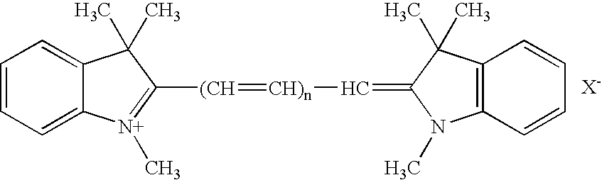
wherein X is an anion, and n is 0, 1, 2, or 3. - The present invention exhibited remarkable effects in the electroplating of copper or an alloy thereof.
- As described above, a flattening treatment is conducted in one embodiment of the present invention to thereby erase the surface irregularities formed in the area where the metal film is not to be formed. In such flattening treatment, the surface irregularities are preferably flattened such that, when the surface irregularities has a surface roughness as represented by the arithmetic average roughness Ra defined by JIS B0601 of 0.01 to 4 μm, the flattening treatment is conducted until the Ra is 0 to 0.005 μm. When the surface irregularities has a surface roughness as represented by the mean spacing of the profile elements RSm also defined by JIS B0601 of 0.005 to 8 μm, the flattening treatment is conducted until the RSm is 10 to 100 μm. When the surface irregularities has a surface roughness as represented by the arithmetic average roughness Ra defined by JIS B0601 of 0.1 to 1 μm, the flattening treatment is conducted until the Ra is 0 to 0.05 μm, and when the surface irregularities has a surface roughness as represented by the mean spacing of the profile elements RSm also defined by JIS B0601 of 0.05 to 2 μm, the flattening treatment is conducted until the RSm is 4 to 40 μm.
- In the present invention, the ratio (T/t) of the thickness (T) of the metal film formed by electroplating in the area provided with the surface irregularities to the thickness (t) of the metal film formed in the area having no surface irregularities can be increased to not less than 1, not less than 10, or not less than 100.
- The metal structure comprising the electrical conductor and the metal film of predetermined pattern formed on the electrical conductor wherein the ratio T/t is not less than 1, and not less than 10 can be used as a reflector of an optical component, or as a heat exchanger. Such metal structure can also be used as an inspection probe or as a mold stamper.
- Next, various embodiments of the present invention are described by referring to the drawings. The results of the Examples and the Comparative Examples are summarized in Table 4.
- A
silicon mold 4 has a wiring pattern with a width of 50 μm formed at an interval of 5 μm as shown inFIG. 1A , and each wiring pattern has trenches having a width of 300 nm and a height of 600 nm formed at an interval of 300 nm. As shown inFIG. 1B , aelectrical conductor substrate 1 in the form of a nickel film was formed on thissilicon mold 4 by electroless plating. After the plating, the nickel film was peeled off thesilicon mold 4 as shown in theFIG. 1C . The surface having irregularities on the nickel film after peeling off the silicon mold was observed, and the shape of the surface irregularities of themold 4 was found to be maintained on the nickel film. Next, theelectrical conductor substrate 1 comprising the nickel film was fixed in a jig for electroplating, and theconductor substrate 1 was electroplated to form ametal film 2 having a particular pattern on theelectrical conductor substrate 1 as shown inFIG. 1D in exploded view and inFIG. 1E in perspective view. Although theelectrical conductor substrate 1 is depicted inFIG. 1E to be partly left uncovered by themetal film 2, the entire surface of theelectrical conductor substrate 1 is actually covered by themetal film 2, and themetal film 2 on the part formed with the surface irregularities is thicker than other parts. The electroplating was conducted by using a plating bath having the composition shown in Table 1. The additive used was 2-[3-(1,3-Dihydro-1,3,3-trimethyl-2H-indol-2-ylidene)-1-pro penyl]-1,3,3-trimethyl-3H-indolium chloride.TABLE 1 Component Concentration (g/dm3) Copper sulfate pentahydrate 64 Sulfuric acid 180 Chloride ion 70 × 10−3 Additive 7 × 10⁻³ - The electroplating was conducted by using a plating time of 20 minutes, a current density of 1.3 A/dm2, a plating bath temperature of 25° C., and by using a phosphorus-containing copper plate for the anode. When the cross section of the substrate was observed after the electroplating, the
metal film 2 after the plating, namely, the copper film had a maximum thickness of 35 μm in the area provided with the surface irregularities, and 0.45 μm in the area provided with no surface irregularities, and the ratio H1/H2 of the film thickness shown inFIG. 12 was 78. As indicated by such results, a metal structure having a metal film preferentially formed in the area provided with the surface irregularities could be produced. - A copper foil having a thickness of 1 mm was used for the
electrical conductor substrate 1 as shown inFIG. 2A . Surface irregularities were then formed on the copper foil by surface roughening as shown inFIG. 2B . Sand blast was used for the surface roughening by blasting alumina fine particles to the copper surface through a mask pattern of 100 μm squares. The roughened copper foil surface was evaluated for the surface roughness of the surface irregularities with a surface roughness measuring apparatus. Arithmetic average roughness Ra defined by JIS B0601 was 0.4 μm, and mean spacing of the profile elements RSm also defined by JIS B0601 was 1.1 μm. After the roughening of the copper surface, the surface was electroplated to form ametal film 2 comprising the electroplated film of copper as shown inFIG. 2C . The electroplating was conducted by using the composition of the plating bath and the plating conditions which were the same as those of the procedure of Example 1 except that the plating time was 25 minutes and the current density was 0.5 A/dm2. - When the cross section of the substrate was observed after the electroplating, the maximum thickness of the plated copper film in the area formed with the surface irregularities was 15 μm, and the maximum film thickness of the area formed with no surface irregularities was 0.1 μm, and the ratio H1/H2 of the film thickness shown in
FIG. 12 was 150. As indicated by such results, a metal structure having a metal film preferentially formed in the area provided with the surface irregularities could be produced as shown inFIGS. 2D and 2E . Although theelectrical conductor substrate 1 is depicted inFIGS. 2D and 2E to have been only partly covered by themetal film 2, the metal film was actually formed on the entire surface of theelectrical conductor substrate 1, and the metal film of the part formed with the surface irregularities was thicker than other parts, as shown inFIG. 2C . - In this Example, the
mold 4 used was a titanium plate as shown inFIG. 3A having a surface irregularity pattern with a width of 10 μm having an arithmetic average roughness Ra defined by JIS B0601 of 0.05 μm, and a mean spacing of the profile elements RSm also defined by JIS B0601 of 0.04 μm. A copper film was formed on this titanium plate by electroplating as shown inFIG. 3B for use as theelectrical conductor substrate 1. After the electroplating, the copper film was peeled off themold 4 as shown inFIG. 3C to use the film for the electrical conductor substrate. Surface irregularities of the copper film after peeling off themold 4 was observed. The surface irregularities had an arithmetic average roughness Ra defined by JIS B0601 of 0.05 μm, and mean spacing of the profile elements RSm also defined by JIS B0601 of 0.04 μm, indicating that the surface configuration of themold 4 had been maintained by the copper film. - Next, as shown in
FIG. 3D , a suspension of copper fine particles was printed to cover the area where the surface irregularities were not to be formed, and annealing was conducted in vacuum at 300° C. for 30 minutes to flatten some parts of the electrical conductor substrate as shown inFIG. 3D . The part covered with the copper fine particles was evaluated for the surface roughness with a surface roughness measuring apparatus. The arithmetic average roughness Ra defined by JIS B0601 was 0.005 μm, and the mean spacing of the profile elements RSm also defined by JIS B0601 was 11 μm, indicating that the copper film surface had been flattened. Next, electroplating was conducted to form a copper film as shown inFIG. 3E as themetal film 2. The electroplating was conducted by using the composition of the plating bath and the plating conditions which were the same as Example 1. - When the cross section of the substrate was observed after the electroplating, the maximum thickness of the plated copper film of the area formed with the surface irregularities was 10 μm, and the maximum thickness of the plated copper film of the area formed with no surface irregularities was 0.5 μm, and the ratio H1/H2 of the film thickness shown in
FIG. 12 was 20. As indicated by such results, a metal structure having a metal film preferentially formed in the area provided with the surface irregularities could be produced. - A copper foil having a thickness of 18 μm was used for the electrical conductor substrate as shown in
FIG. 4A . The entire surface of the electrical conductor substrate was roughened to form the surface irregularities as shown inFIG. 4B . The roughening was conducted by using MultiBond manufactured by Nippon MacDermid Co., Ltd., and by the procedure shown in Table 2. Exemplary other copper roughening solutions that can be used include MECetchBOND manufactured by MEC Company Ltd., Circubond manufactured by Shipley Far East Ltd., and AlphaPREP manufactured by Alpha Metals Japan Ltd.TABLE 2 Temperature Step Treating solution (° C.) Time (Sec.) 1 5 vol % sulfuric acid 25 30 2 Pure water (running water) 22 60 3 20 vol % MB-100B 25 30 2.9 vol % MB- 100C 4 5 vol % sulfuric acid 32 15 15 vol % MB- 100A 2 vol % MB-100B 2.9 vol % MB- 100C 5 Pure water (running water) 22 60 - The roughened copper foil surface was evaluated for the surface roughness with a surface roughness measuring apparatus. The arithmetic average roughness Ra defined by JIS B0601 was 0.5 μm, and the mean spacing of the profile elements RSm also defined by JIS B0601 was 1.3 μm. Next, as shown in
FIG. 4C , the surface irregularities were flattened except for the area that was to be covered by the metal film by electroplating. The flattening was conducted by covering the area with a solution containing copper fine particles by screen printing, and annealing the particles in vacuum at 350° C. for 30 minutes. The part printed with the copper fine particles was evaluated for the surface roughness with a surface roughness measuring apparatus. The arithmetic average roughness Ra defined by JIS B0601 was 0.005 μm, and the mean spacing of the profile elements RSm also defined by JIS B0601 was 11 μm, indicating that the copper film surface had been flattened. Next, electroplating was conducted to form the copper film and produce the metal structure as shown inFIG. 4D . The electroplating was conducted by using the composition of the plating bath and the plating conditions which were the same as those used in Example 1. - When the cross section of the substrate was observed after the electroplating, the maximum film thickness of the area formed with the surface irregularities was 10 μm, and the maximum thickness of the plated copper film of the area formed with no surface irregularities was 0.4 μm, and the ratio H1/H2 of the film thickness shown in
FIG. 12 was 25. As indicated by such results, a metal structure having a metal film preferentially formed in the area provided with the surface irregularities could be formed. - An epoxy resin plate was used for the
electric insulator substrate 3, and surface irregularities were formed as shown inFIG. 5A by pushing thesilicon mold 4 against the surface of theelectric insulator substrate 3. Thesilicon mold 4 had a wiring pattern with a width of 50 μm formed at an interval of 5 μm as shown inFIG. 1A , and each wiring pattern had ridges having a width of 250 nm and a height of 400 nm formed at an interval of 250 nm formed to a width of 10 μm. By pressing the mold against the electric insulator substrate that had been heated to a temperature near the glass transition temperature, theelectric insulator substrate 3 could be softened and deformed to replicate the shape of themold 4. After cooling theelectric insulator substrate 3 and themold 4 to 25° C., theelectric insulator substrate 3 was peeled off themold 4 to produce the electric insulator substrate as shown inFIG. 5B . - Next, a nickel/chromium film having a ratio of nickel to chromium of 1:1 was formed on the surface of the
electric insulator substrate 3 to a thickness of 10 nm, and on the nickel/chromium film was formed a copper film of 100 nm by chemical vapor deposition. The electric insulator substrate having the nickel/chromium film and the copper film formed is shown inFIG. 5C . InFIG. 5C , the nickel/chromium film and the copper film are together referred to as theelectrical conductor 5. The surface irregularities after forming theelectrical conductor 5 was observed, and the shape of the surface irregularities of theelectric insulator substrate 3 were found to be maintained by theelectrical conductor 5. Immediately after forming theelectrical conductor 5, electroplating was conducted to form the copper film. The electroplating was conducted by using the composition of the plating bath and the plating conditions which were the same as those used in Example 1. - The maximum thickness of the plated copper film in the area formed with the surface irregularities was 10 μm, and the maximum thickness of the plated copper film of the area formed with no surface irregularities was 0.3 μm, and the ratio H1/H2 of the film thickness shown in
FIG. 12 was 33. As indicated by such results, a metal structure having a metal film preferentially formed in the area provided with the surface irregularities could be formed. - A polyimide resin film having a thickness of 25 μm was used for the electric insulator substrate. The surface of the
electric insulator substrate 3 shown inFIG. 6A was roughened to form surface irregularities as shown inFIG. 6B . The roughening was conducted by the steps as shown in Table 3. The treating solution used in the roughening is not limited to the mixture of the potassium permanganate and the sodium hydroxide, and exemplary other solutions include a mixed solution of chromic acid and sulfuric acid, and a mixed solution of chromic acid and fluoroboric acid.TABLE 3 Temperature Time Step Treating solution (° C.) (Sec.) 1 50 g/dm3 potassium permanganate 80 5 1 mol/dm3 sodium hydroxide 2 0.5 vol % sulfuric acid 40 5 0.2 vol % hydroxylamine sulfate - The surface irregularities of the polyimide film after the roughening were evaluated with a surface roughness measuring apparatus. The arithmetic average roughness Ra defined by JIS B0601 was 2.0 μm, and the mean spacing of the profile elements RSm also defined by JIS B0601 was 4.0 μm. Next, a
electrical conductor 5 having a wiring width of 10 μm was formed on a part of theelectric insulator substrate 3 by sputtering through a mask. Theelectrical conductor 1 comprises a laminate of nickel film having a thickness of 0.01 μm and a copper film having a thickness of 0.5 μm formed on the nickel film. Theelectrical conductor 5 is not limited to such laminate of the nickel and copper films, and another example of such electrical conductor is a laminate of chromium and copper films.FIG. 6C shows theelectrical conductor 5 formed on theelectric insulator substrate 3. The surface irregularities after forming theelectrical conductor 5 were evaluated with a surface roughness measuring apparatus. The arithmetic average roughness Ra defined by JIS B0601 was 2.0 μm, and the mean spacing of the profile elements RSm also defined by JIS B0601 was 4.0 μm, indicating that the shape of the surface irregularities of theelectric insulator substrate 3 had been maintained. - Immediately after forming the
electrical conductor 5, electroplating was conducted to form the plated copper film. The electroplating was conducted by using the composition of the plating bath and the plating conditions, which is the same as those used in Example 1. The maximum thickness of the plated copper film in the area formed with the surface irregularities was 15 μm, and the copper film was preferentially plated in the area formed with theelectrical conductor 5. The ratio H1/H2 of the film thickness shown inFIG. 12 was 27. As indicated by such results, a metal structure having a metal film preferentially formed in the area provided with the surface irregularities could be produced. - Polyamic acid was applied on a copper foil having surface irregularities with the arithmetic average roughness Ra defined by JIS B0601 of 1.0 μm and mean spacing of the profile elements RSm also defined by JIS B0601 of 1.1 μm, and the foil was heated to produce a polyimide film. The copper foil was then removed by etching with a solution containing sulfuric acid and hydrogen peroxide to produce the
electric insulator substrate 3 as shown inFIG. 7A . Theelectric insulator substrate 3 had a surface roughness with the arithmetic average roughness Ra defined by JIS B0601 of 1.0 μm and the mean spacing of the profile elements RSm also defined by JIS B0601 of 1.1 μm. Next, as shown inFIG. 7B , asilicon mold 4 provided with a groove having a width of 10 μm was pressed against theelectric insulator substrate 3 that had been heated to a temperature near the glass transition temperature with the temperature maintained during the pressing, and avoiding the groove portion of themold 4 from being brought in contact with theelectric insulator substrate 3. - Next, the
electric insulator substrate 3 and themold 4 were cooled to 25° C., and they were separated from each other by peeling to produce theelectric insulator substrate 3 as shown inFIG. 7C having a part of its surface flattened. When the surface roughness of the flattened part was measured by a surface roughness surface roughness measuring apparatus, the arithmetic average roughness Ra defined by JIS B0601 was 0.006 μm, and the mean spacing of the profile elements RSm also defined by JIS B0601 was 9 μm. Next, a film of 10 nm comprising chromium and nickel at a ratio of 1:1 was formed on theelectric insulator substrate 3 by sputtering, and on this chromium/nickel film was formed a copper film of 100 nm by vapor deposition.FIG. 7D shows theelectric insulator substrate 3 having a laminate of the nickel/chromium film and the copper film deposited on theelectric insulator substrate 3 in the area having the surface irregularities. The surface irregularities were evaluated for their roughness, and the arithmetic average roughness Ra defined by JIS B0601 was 1.0 μm, and the mean spacing of the profile elements RSm also defined by JIS B0601 was 1.1 μm, indicating that the shape of the surface irregularities of theelectric insulator substrate 3 had been maintained. - Immediately after forming the
electrical conductor 5, electroplating was conducted to form the copper film. The electroplating was conducted by using the composition of the plating bath and the plating conditions which were the same as those used in Example 1. The maximum thickness of the plated copper film in the area formed with the surface irregularities was 10 μm, and the maximum thickness of the plated copper film of the area formed with no surface irregularities was 0.33 μm. and the ratio H1/H2 of the film thickness shown inFIG. 12 was 30. As indicated by such results, a metal structure having a metal film preferentially formed in the area provided with the surface irregularities could be produced. - An
electric insulator substrate 3 comprising polyimide resin was used. Surface of the polyimide resin as shown inFIG. 8A was roughened by using a mixed solution of chromic acid and sulfuric acid to form the surface irregularities as shown inFIG. 8B . When the surface roughness of the area formed with the surface irregularities was measured, the arithmetic average roughness Ra defined by JIS B0601 was 1.2 μm, and the mean spacing of the profile elements RSm also defined by JIS B0601 was 0.8 μm. Next, as shown inFIG. 8C , theelectric insulator substrate 3 was partly covered with anelectric insulator 6 comprising a photocurable resin by screen printing, and the resin was cured to flatten the surface irregularities. When the area where the surface irregularities had been flattened by filling the resin was evaluated for the surface roughness, the arithmetic average roughness Ra defined by JIS B0601 was 0.006 μm, and the mean spacing of the profile elements RSm also defined by JIS B0601 was 9 μm. - Next, a nickel/chromium film having a nickel to chromium ratio of 1:1 was formed to a thickness of 10 nm by sputtering on the
electric insulator substrate 3 in the area having the surface irregularities, and a copper film of 100 nm was then formed on the nickel/chromium film by vapor deposition to thereby form theelectrical conductor 5 comprising the nickel/chromium film and the copper film as shown inFIG. 8D . When the surface irregularities after the forming of theelectrical conductor 5 were evaluated for the surface roughness, the arithmetic average roughness Ra defined by JIS B0601 was 1.2 μm, and the mean spacing of the profile elements RSm also defined by JIS B0601 was 0.8 μm, indicating that the shape of the surface irregularities of theelectric insulator substrate 3 had been maintained by theelectrical conductor 5. - Immediately after forming the
electrical conductor 5, electroplating was conducted to form the plated copper film as shown inFIG. 8E . The electroplating was conducted by using the composition of the plating bath and the plating conditions which were the same as those used in Example 1. Maximum thickness of the plated copper film in the area formed with surface irregularities was 15 μm, and 0.55 μm in the area formed with no surface irregularities. The ratio H1/H2 of the film thickness shown inFIG. 12 was 27. As a consequence, a metal structure having a metal film could be preferentially formed in the area provided with the surface irregularities. - A metal structure having the configuration of
FIG. 9A was produced by repeating the procedure of Example 1 except that the substance used was the one indicated in Table 4. Next, the copper film of the part having no surface irregularities was removed by using a copper etchant (MECBRITE manufactured by MEC Company Ltd.) to thereby produce the cross section as shown inFIG. 9B . As a consequence, a metal structure comprising the nickel film and the overlying plated copper film could be produced. - A metal structure was produced by repeating the procedure of Example 1 except that the additive used was the one indicated in Table 4. Cross section of the metal substrate is shown in
FIG. 10A , which is the same asFIG. 5D . Next, the copper film in the area having no surface irregularities was removed by using an aqueous solution containing sulfuric acid and hydrogen peroxide to realize the state as shown inFIG. 10B . Theelectrical conductor 5 comprising the nickel/chromium film and the copper film was removed by using an aqueous solution containing potassium permanganate to realize the state as shownFIG. 10C . As a consequence, a metal structure could be produced in the predetermined part of the electric insulator substrate having the surface irregularities. - On the
electric insulator substrate 3 comprising the glass substrate shown inFIG. 11A was printed a dispersion of silver fine particles having an average particle size of 5 nm by ink jet printing as shown inFIG. 11B to form aelectrical conductor 5 comprising a silver film having a wiring width of 20 μm and a thickness of 0.2 μm. Theelectric insulator substrate 3 was then heated to a temperature of 300° C. for fusion of silver fine particles. The surface irregularities on the silver film surface formed by the silver fine particles were evaluated with a surface roughness measuring apparatus. The arithmetic average roughness Ra defined by JIS B0601 was 0.01 μm, and the mean spacing of the profile elements RSm also defined by JIS B0601 was 0.02 μm. - Immediately after forming the silver film, electroplating was conducted to form the copper film as the
metal film 2. The electroplating was conducted by using the composition of the plating bath and the plating conditions which were the same as those used in Example 1. When the cross section of the substrate was observed after the electroplating, the plated film developed in vertical direction only in the area formed with the surface irregularities, and no growth in the horizontal direction was found. As a consequence, a metal structure having the metal film only in the area of predetermined pattern having the surface irregularities could be produced. - A metal structure was produced by repeating the procedure of Example 2 except that the roughening was not conducted. When the cross section of the substrate was observed, preferential growth of the plating film had not taken place, and the ratio H1/H2 of the film thickness shown in
FIG. 12 was 1.0. In this Comparative Example, a metal structure could not be formed in the predetermined pattern.TABLE 4 Concen- tration Ra of the RSm of the of the surface surface Kind of additive Current irregular- irregular- the (mg/ density No. ities ities additive dm3) (A/dm2) H1/H2 Ex. 1 0.15 0.6 A-2 7.0 1.3 78 Ex. 2 0.4 1.1 A-2 7.0 0.5 150 Ex. 3 0.05 0.04 A-2 7.0 1.3 20 Ex. 4 0.5 1.3 A-2 7.0 1.3 25 Ex. 5 0.2 0.5 A-2 7.0 1.3 33 Ex. 6 2.0 4.0 A-2 7.0 1.3 27 Ex. 7 1.0 1.1 A-2 7.0 1.3 30 Ex. 8 1.2 0.8 A-2 7.0 1.3 27 Ex. 9 0.15 0.6 A-1 3.0 1.3 77 A-4 3.0 Ex. 10 0.2 0.5 A-2 7.0 1.3 64 B 100 C 2 Ex. 11 0.01 0.02 A-2 7.0 1.3 — Comp. 0.007 10 A-2 7.0 1.3 1.0 Ex. 1 - The symbols used in the column of the “Type of the additive” in Table 4 stand for the following chemical substances.
- A-1:
-
- 2-[(1,3-dihydro-1,3,3-trimethyl-2H-indol-2-ylidene)-methyl]-1,3,3-trimethyl-3H-indolium perchlorate
A-2: - 2-[3-(1,3-dihydro-1,3,3-trimethyl-2H-indol-2-ylidene)-1-pro penyl]-1,3,3-trimethyl-3H-indolium chloride
A-3: - 2-[5-(1,3-dihydro-1,3,3-trimethyl-2H-indol-2-ylidene)-1,3-p entadienyl]-1,3,3-trimethyl-3H-indolium iodide
A-4: - 2-[7-(1,3-dihydro-1,3,3-trimethyl-2H-indol-2-ylidene)-1,3,5-heptatrienyl]-1,3,3-trimethyl-3H-indolium iodide
B: polyethylene glycol (average molecular weight, 2000)
C: bis(3-sulfopropyl) disulfide - The present invention enables formation of a metal body or film of fine pattern at a predetermined position without using any resist mask, and therefore, it can be used in producing an optical component, stamper used as a mold, an inspection probe, a micromachine, and the like. The present invention can also be used in producing various components, for example, to impart the component with water repellency or to alter the appearance. The applicability of this invention is unlimited.
Claims (20)
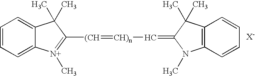
Applications Claiming Priority (2)
| Application Number | Priority Date | Filing Date | Title |
|---|---|---|---|
| JP2005019395A JP4468191B2 (en) | 2005-01-27 | 2005-01-27 | Metal structure and manufacturing method thereof |
| JP2005-019395 | 2005-01-27 |
Publications (2)
| Publication Number | Publication Date |
|---|---|
| US20060180472A1 true US20060180472A1 (en) | 2006-08-17 |
| US7922887B2 US7922887B2 (en) | 2011-04-12 |
Family
ID=36814573
Family Applications (1)
| Application Number | Title | Priority Date | Filing Date |
|---|---|---|---|
| US11/340,570 Expired - Fee Related US7922887B2 (en) | 2005-01-27 | 2006-01-27 | Metal structure and method of its production |
Country Status (3)
| Country | Link |
|---|---|
| US (1) | US7922887B2 (en) |
| JP (1) | JP4468191B2 (en) |
| CN (1) | CN1831205B (en) |
Cited By (4)
| Publication number | Priority date | Publication date | Assignee | Title |
|---|---|---|---|---|
| US20070287289A1 (en) * | 2006-06-12 | 2007-12-13 | Toshio Haba | Production method of conductive pattern |
| US20090008257A1 (en) * | 2006-08-18 | 2009-01-08 | Fujifilm Corporation | Method of producing stamper for optical recording medium, method of producing substrate, and method of producing optical recording medium |
| US20090057156A1 (en) * | 2007-08-30 | 2009-03-05 | Hitachi Cable, Ltd. | Production method for wiring and vias |
| US20120125887A1 (en) * | 2010-07-26 | 2012-05-24 | Hamamatsu Photonics K.K. | Method for manufacturing light-absorbing substrate and method for manufacturing mold for making same |
Families Citing this family (1)
| Publication number | Priority date | Publication date | Assignee | Title |
|---|---|---|---|---|
| CN109712897B (en) * | 2017-10-26 | 2020-12-18 | 中芯国际集成电路制造(上海)有限公司 | Semiconductor device, manufacturing method thereof and electronic device |
Citations (17)
| Publication number | Priority date | Publication date | Assignee | Title |
|---|---|---|---|---|
| US5527734A (en) * | 1990-10-05 | 1996-06-18 | U.S. Philips Corporation | Method of manufacturing a semiconductor device by forming pyramid shaped bumps using a stabilizer |
| US5631119A (en) * | 1993-07-29 | 1997-05-20 | Fuji Photo Film Co., Ltd. | Image-forming material and image formation process |
| US6245676B1 (en) * | 1998-02-20 | 2001-06-12 | Nec Corporation | Method of electroplating copper interconnects |
| US6287950B1 (en) * | 2000-02-03 | 2001-09-11 | Taiwan Semiconductor Manufacturing Co., Ltd. | Bonding pad structure and manufacturing method thereof |
| US6316059B1 (en) * | 1992-06-29 | 2001-11-13 | U.S. Philips Corporation | Method of providing a metal pattern on glass in an electroless process |
| US6326556B1 (en) * | 1996-12-13 | 2001-12-04 | Ibiden Co., Ltd. | Multilayered printed wiring board |
| US6387807B1 (en) * | 2001-01-30 | 2002-05-14 | Speedfam-Ipec Corporation | Method for selective removal of copper |
| US20020084191A1 (en) * | 2000-11-16 | 2002-07-04 | Toshio Haba | Electric copper plating liquid and process for manufacturing semiconductor integrated circuit device using same |
| US6511588B1 (en) * | 1999-09-20 | 2003-01-28 | Hitachi, Ltd. | Plating method using an additive |
| US6553662B2 (en) * | 2001-07-03 | 2003-04-29 | Max Levy Autograph, Inc. | Method of making a high-density electronic circuit |
| US20030178547A1 (en) * | 2000-08-01 | 2003-09-25 | Taiwan Nano Electro-Optical Technology Co., Ltd. | Process for producing an article with a microstructure |
| US20040066732A1 (en) * | 2001-07-02 | 2004-04-08 | Hiroyuki Takemoto | Optical information recording medium, originial disk for optical information recording medium, and method of manufacturing the original disk |
| US20040134786A1 (en) * | 2002-08-28 | 2004-07-15 | Ritek Corporation | Mold for a V-groove fiber array base block and fabrication method thereof |
| US6825541B2 (en) * | 2002-10-09 | 2004-11-30 | Taiwan Semiconductor Manufacturing Co., Ltd | Bump pad design for flip chip bumping |
| US20050045488A1 (en) * | 2002-03-05 | 2005-03-03 | Enthone Inc. | Copper electrodeposition in microelectronics |
| US20050089671A1 (en) * | 1999-04-23 | 2005-04-28 | Takeshi Kubota | Shaped sheet and method for producing the same |
| US7144490B2 (en) * | 2003-11-18 | 2006-12-05 | International Business Machines Corporation | Method for selective electroplating of semiconductor device I/O pads using a titanium-tungsten seed layer |
Family Cites Families (22)
| Publication number | Priority date | Publication date | Assignee | Title |
|---|---|---|---|---|
| CN1034191A (en) * | 1989-01-14 | 1989-07-26 | 张喻沅 | Produce the technology of high-grade wine-bottle |
| JPH03256603A (en) | 1990-03-08 | 1991-11-15 | Seiko Epson Corp | Chuck fixing device |
| JPH05334163A (en) | 1992-05-29 | 1993-12-17 | Hitachi Ltd | Exclusive control system for shared memory between plural systems |
| JP2910546B2 (en) | 1993-12-28 | 1999-06-23 | 日本電気株式会社 | Manufacturing method of reflector |
| TW312079B (en) | 1994-06-06 | 1997-08-01 | Ibm | |
| JPH0963756A (en) | 1995-08-22 | 1997-03-07 | Tomonokai Rikagaku Kenkyusho:Kk | Desk thermal mat |
| US5725788A (en) | 1996-03-04 | 1998-03-10 | Motorola | Apparatus and method for patterning a surface |
| JPH10338213A (en) | 1997-06-06 | 1998-12-22 | Masaru Kinoshita | Apparatus for covering object to be overlaid with heat-shrinkable tube |
| JP2000158157A (en) | 1998-11-27 | 2000-06-13 | Toshiko:Kk | Minute convex/concave shaped material, coating structural material using it, lining substrate, and powder fluid transferring member |
| JP2000248397A (en) | 1999-02-26 | 2000-09-12 | Electroplating Eng Of Japan Co | Copper sulfate plating solution and electrolytic plating method using the same |
| SG76591A1 (en) * | 1999-02-27 | 2000-11-21 | Aem Tech Engineers Pte Ltd | Method for selective plating of a metal substrate using laser developed masking layer and apparatus for carrying out the method |
| JP4408177B2 (en) | 2000-12-14 | 2010-02-03 | 大日本印刷株式会社 | Method for producing pattern forming body |
| JP4392168B2 (en) * | 2001-05-09 | 2009-12-24 | 荏原ユージライト株式会社 | Copper plating bath and substrate plating method using the same |
| TW584899B (en) | 2001-07-20 | 2004-04-21 | Nutool Inc | Planar metal electroprocessing |
| JP2003243399A (en) | 2001-12-11 | 2003-08-29 | Sony Corp | Method for forming semiconductor device |
| JP3561504B2 (en) | 2002-02-25 | 2004-09-02 | 日本金属株式会社 | Stainless steel conductive member and method of manufacturing the same |
| JP2003317735A (en) | 2002-04-18 | 2003-11-07 | Nec Corp | Solid high polymer electrolyte fuel cell, method for manufacturing solid high polymer electrolyte film for fuel cell and fuel cell |
| US7198705B2 (en) | 2002-12-19 | 2007-04-03 | Texas Instruments Incorporated | Plating-rinse-plating process for fabricating copper interconnects |
| JP4312465B2 (en) | 2003-01-23 | 2009-08-12 | 株式会社荏原製作所 | Plating method and plating apparatus |
| JP2005051151A (en) | 2003-07-31 | 2005-02-24 | Seiko Epson Corp | Manufacturing method for conductive layer, substrate with conductive layer and electronic device |
| JP2005050965A (en) | 2003-07-31 | 2005-02-24 | Ngk Spark Plug Co Ltd | Wiring board and its manufacturing method |
| JP4665531B2 (en) | 2005-01-27 | 2011-04-06 | 日立電線株式会社 | Wiring board manufacturing method |
-
2005
- 2005-01-27 JP JP2005019395A patent/JP4468191B2/en not_active Expired - Fee Related
-
2006
- 2006-01-27 CN CN2006100024247A patent/CN1831205B/en not_active Expired - Fee Related
- 2006-01-27 US US11/340,570 patent/US7922887B2/en not_active Expired - Fee Related
Patent Citations (18)
| Publication number | Priority date | Publication date | Assignee | Title |
|---|---|---|---|---|
| US5527734A (en) * | 1990-10-05 | 1996-06-18 | U.S. Philips Corporation | Method of manufacturing a semiconductor device by forming pyramid shaped bumps using a stabilizer |
| US6316059B1 (en) * | 1992-06-29 | 2001-11-13 | U.S. Philips Corporation | Method of providing a metal pattern on glass in an electroless process |
| US5631119A (en) * | 1993-07-29 | 1997-05-20 | Fuji Photo Film Co., Ltd. | Image-forming material and image formation process |
| US6326556B1 (en) * | 1996-12-13 | 2001-12-04 | Ibiden Co., Ltd. | Multilayered printed wiring board |
| US6245676B1 (en) * | 1998-02-20 | 2001-06-12 | Nec Corporation | Method of electroplating copper interconnects |
| US20050089671A1 (en) * | 1999-04-23 | 2005-04-28 | Takeshi Kubota | Shaped sheet and method for producing the same |
| US6511588B1 (en) * | 1999-09-20 | 2003-01-28 | Hitachi, Ltd. | Plating method using an additive |
| US6287950B1 (en) * | 2000-02-03 | 2001-09-11 | Taiwan Semiconductor Manufacturing Co., Ltd. | Bonding pad structure and manufacturing method thereof |
| US20030178547A1 (en) * | 2000-08-01 | 2003-09-25 | Taiwan Nano Electro-Optical Technology Co., Ltd. | Process for producing an article with a microstructure |
| US20020084191A1 (en) * | 2000-11-16 | 2002-07-04 | Toshio Haba | Electric copper plating liquid and process for manufacturing semiconductor integrated circuit device using same |
| US20050087447A1 (en) * | 2000-11-16 | 2005-04-28 | Toshio Haba | Electric copper plating liquid and process for manufacturing semiconductor integrated circuit device using same |
| US6387807B1 (en) * | 2001-01-30 | 2002-05-14 | Speedfam-Ipec Corporation | Method for selective removal of copper |
| US20040066732A1 (en) * | 2001-07-02 | 2004-04-08 | Hiroyuki Takemoto | Optical information recording medium, originial disk for optical information recording medium, and method of manufacturing the original disk |
| US6553662B2 (en) * | 2001-07-03 | 2003-04-29 | Max Levy Autograph, Inc. | Method of making a high-density electronic circuit |
| US20050045488A1 (en) * | 2002-03-05 | 2005-03-03 | Enthone Inc. | Copper electrodeposition in microelectronics |
| US20040134786A1 (en) * | 2002-08-28 | 2004-07-15 | Ritek Corporation | Mold for a V-groove fiber array base block and fabrication method thereof |
| US6825541B2 (en) * | 2002-10-09 | 2004-11-30 | Taiwan Semiconductor Manufacturing Co., Ltd | Bump pad design for flip chip bumping |
| US7144490B2 (en) * | 2003-11-18 | 2006-12-05 | International Business Machines Corporation | Method for selective electroplating of semiconductor device I/O pads using a titanium-tungsten seed layer |
Cited By (5)
| Publication number | Priority date | Publication date | Assignee | Title |
|---|---|---|---|---|
| US20070287289A1 (en) * | 2006-06-12 | 2007-12-13 | Toshio Haba | Production method of conductive pattern |
| US20090008257A1 (en) * | 2006-08-18 | 2009-01-08 | Fujifilm Corporation | Method of producing stamper for optical recording medium, method of producing substrate, and method of producing optical recording medium |
| US20090057156A1 (en) * | 2007-08-30 | 2009-03-05 | Hitachi Cable, Ltd. | Production method for wiring and vias |
| US20120125887A1 (en) * | 2010-07-26 | 2012-05-24 | Hamamatsu Photonics K.K. | Method for manufacturing light-absorbing substrate and method for manufacturing mold for making same |
| US9108269B2 (en) * | 2010-07-26 | 2015-08-18 | Hamamatsu Photonics K. K. | Method for manufacturing light-absorbing substrate and method for manufacturing mold for making same |
Also Published As
| Publication number | Publication date |
|---|---|
| US7922887B2 (en) | 2011-04-12 |
| JP4468191B2 (en) | 2010-05-26 |
| CN1831205A (en) | 2006-09-13 |
| CN1831205B (en) | 2011-06-15 |
| JP2006206950A (en) | 2006-08-10 |
Similar Documents
| Publication | Publication Date | Title |
|---|---|---|
| US20060163725A1 (en) | Wiring board and production method thereof | |
| US20180279482A1 (en) | Surface-treated copper foil, copper foil with carrier, substrate, resin substrate, printed wiring board, copper clad laminate and method for producing printed wiring board | |
| KR100729005B1 (en) | Composite copper foil and manufacturing method thereof | |
| JP4642229B2 (en) | Apparatus and method for electrolytically depositing copper on a semiconductor work member | |
| US10455704B2 (en) | Method for copper filling of a hole in a component carrier | |
| TW200539774A (en) | Method of manufacturing a circuit carrier and the use of the method | |
| US7922887B2 (en) | Metal structure and method of its production | |
| KR101298999B1 (en) | Embedded Copper foil for fine pattern | |
| JP2010010500A (en) | Copper circuit component and its production method | |
| JP2007180089A (en) | Manufacturing method of resin molded component with circuit conductor pattern | |
| KR100435298B1 (en) | Electrolytic copper foil | |
| CN102014589A (en) | Method of manufacturing printed wiring board | |
| JP4862508B2 (en) | Conductor pattern forming method | |
| JP2006199027A (en) | Mask and its manufacturing process for stencil printing | |
| US7776199B2 (en) | Printed wiring board and production method thereof | |
| JP2741997B2 (en) | Manufacturing method of three-dimensional circuit board | |
| JP2005161667A (en) | Manufacturing method of micromold | |
| US20040060728A1 (en) | Method for producing electroconductive structures | |
| JP4134327B2 (en) | Metal mask and manufacturing method thereof | |
| US20120279775A1 (en) | Circuit board viaholes and method of manufacturing the same | |
| JP2006073754A (en) | Manufacturing method for electrical component | |
| KR102021428B1 (en) | A nickel electroforming method for producing a micro-mesh sheet and a nickel micro-mesh sheet produced by the method | |
| JP2006032476A (en) | Via filling plating method | |
| JP2002025573A (en) | Manufacturing method of electrode for fuel cell | |
| US20200006135A1 (en) | Method and Plater Arrangement for Failure-Free Copper Filling of a Hole in a Component Carrier |
Legal Events
| Date | Code | Title | Description |
|---|---|---|---|
| AS | Assignment |
Owner name: HITACHI, LTD., JAPAN Free format text: ASSIGNMENT OF ASSIGNORS INTEREST;ASSIGNORS:HABA, TOSHIO;YOSHIDA, HIROSHI;AKAHOSHI, HARUO;AND OTHERS;SIGNING DATES FROM 20060113 TO 20060116;REEL/FRAME:017511/0826 Owner name: HITACHI, LTD., JAPAN Free format text: ASSIGNMENT OF ASSIGNORS INTEREST;ASSIGNORS:HABA, TOSHIO;YOSHIDA, HIROSHI;AKAHOSHI, HARUO;AND OTHERS;REEL/FRAME:017511/0826;SIGNING DATES FROM 20060113 TO 20060116 |
|
| STCF | Information on status: patent grant |
Free format text: PATENTED CASE |
|
| FPAY | Fee payment |
Year of fee payment: 4 |
|
| FEPP | Fee payment procedure |
Free format text: MAINTENANCE FEE REMINDER MAILED (ORIGINAL EVENT CODE: REM.); ENTITY STATUS OF PATENT OWNER: LARGE ENTITY |
|
| LAPS | Lapse for failure to pay maintenance fees |
Free format text: PATENT EXPIRED FOR FAILURE TO PAY MAINTENANCE FEES (ORIGINAL EVENT CODE: EXP.); ENTITY STATUS OF PATENT OWNER: LARGE ENTITY |
|
| STCH | Information on status: patent discontinuation |
Free format text: PATENT EXPIRED DUE TO NONPAYMENT OF MAINTENANCE FEES UNDER 37 CFR 1.362 |
|
| FP | Lapsed due to failure to pay maintenance fee |
Effective date: 20190412 |