US20050151110A1 - Fluoroether refrigerant compositions and uses thereof - Google Patents
Fluoroether refrigerant compositions and uses thereof Download PDFInfo
- Publication number
- US20050151110A1 US20050151110A1 US11/014,003 US1400304A US2005151110A1 US 20050151110 A1 US20050151110 A1 US 20050151110A1 US 1400304 A US1400304 A US 1400304A US 2005151110 A1 US2005151110 A1 US 2005151110A1
- Authority
- US
- United States
- Prior art keywords
- composition
- propane
- difluoromethoxy
- tetrafluoroethane
- ethoxy
- Prior art date
- Legal status (The legal status is an assumption and is not a legal conclusion. Google has not performed a legal analysis and makes no representation as to the accuracy of the status listed.)
- Abandoned
Links
- YZRXRLLRSPQHDK-UHFFFAOYSA-N CCCCCCC1CCCC(=O)O1 Chemical compound CCCCCCC1CCCC(=O)O1 YZRXRLLRSPQHDK-UHFFFAOYSA-N 0.000 description 2
- IBVDLVUXSDSVQF-UHFFFAOYSA-N CCCCCCC1CCOC1=O Chemical compound CCCCCCC1CCOC1=O IBVDLVUXSDSVQF-UHFFFAOYSA-N 0.000 description 2
- ZFKUTGNRVJOCIO-WDEREUQCSA-N CCCCCCC[C@@H]1C[C@H](C)OC1=O Chemical compound CCCCCCC[C@@H]1C[C@H](C)OC1=O ZFKUTGNRVJOCIO-WDEREUQCSA-N 0.000 description 2
- 0 [1*]/C([2*])=C1\C(=O)O[C@]([5*])([6*])[C@]1([3*])[4*].[1*][C@@]1([2*])C(=O)O[C@]([5*])([6*])[C@]1([3*])[4*].[1*][C@@]1([2*])C(=O)O[C@]([7*])([8*])[C@]([5*])([6*])[C@]1([3*])[4*] Chemical compound [1*]/C([2*])=C1\C(=O)O[C@]([5*])([6*])[C@]1([3*])[4*].[1*][C@@]1([2*])C(=O)O[C@]([5*])([6*])[C@]1([3*])[4*].[1*][C@@]1([2*])C(=O)O[C@]([7*])([8*])[C@]([5*])([6*])[C@]1([3*])[4*] 0.000 description 2
- YHEFXCQGOIEIDG-RRKGBCIJSA-N CC(CC=C1C[C@@H](C)OC1=O)CC(C)(C)C Chemical compound CC(CC=C1C[C@@H](C)OC1=O)CC(C)(C)C YHEFXCQGOIEIDG-RRKGBCIJSA-N 0.000 description 1
- BDQJRNACUDIFLF-GLXQMMQGSA-N CC(CC[C@@H]1C[C@H](C)OC1=O)CC(C)(C)C Chemical compound CC(CC[C@@H]1C[C@H](C)OC1=O)CC(C)(C)C BDQJRNACUDIFLF-GLXQMMQGSA-N 0.000 description 1
- HJLVPHHUURFMLO-FLIBITNWSA-N CC1C/C(=C/C2CCCCC2)C(=O)O1 Chemical compound CC1C/C(=C/C2CCCCC2)C(=O)O1 HJLVPHHUURFMLO-FLIBITNWSA-N 0.000 description 1
- DALGWLJAONUZJZ-UHFFFAOYSA-N CC=C1CC(C)OC1=O Chemical compound CC=C1CC(C)OC1=O DALGWLJAONUZJZ-UHFFFAOYSA-N 0.000 description 1
- FEMNIQHEULUJGS-UHFFFAOYSA-N CCC=C1CC(C)OC1=O Chemical compound CCC=C1CC(C)OC1=O FEMNIQHEULUJGS-UHFFFAOYSA-N 0.000 description 1
- BHHYZKGIWKJVAL-UHFFFAOYSA-N CCCC=C1CC(C)OC1=O Chemical compound CCCC=C1CC(C)OC1=O BHHYZKGIWKJVAL-UHFFFAOYSA-N 0.000 description 1
- IPBFYZQJXZJBFQ-UHFFFAOYSA-N CCCCC1CCC(=O)O1 Chemical compound CCCCC1CCC(=O)O1 IPBFYZQJXZJBFQ-UHFFFAOYSA-N 0.000 description 1
- BEUIZLAUWLZVEB-UHFFFAOYSA-N CCCCC=C1CC(C)OC1=O Chemical compound CCCCC=C1CC(C)OC1=O BEUIZLAUWLZVEB-UHFFFAOYSA-N 0.000 description 1
- OALYTRUKMRCXNH-UHFFFAOYSA-N CCCCCC1CCC(=O)O1 Chemical compound CCCCCC1CCC(=O)O1 OALYTRUKMRCXNH-UHFFFAOYSA-N 0.000 description 1
- GHBSPIPJMLAMEP-UHFFFAOYSA-N CCCCCC1CCCC(=O)O1 Chemical compound CCCCCC1CCCC(=O)O1 GHBSPIPJMLAMEP-UHFFFAOYSA-N 0.000 description 1
- CAJHMRZCSCVDAF-UHFFFAOYSA-N CCCCCC=C1CC(C)OC1=O Chemical compound CCCCCC=C1CC(C)OC1=O CAJHMRZCSCVDAF-UHFFFAOYSA-N 0.000 description 1
- IFYYFLINQYPWGJ-UHFFFAOYSA-N CCCCCCC1CCC(=O)O1 Chemical compound CCCCCCC1CCC(=O)O1 IFYYFLINQYPWGJ-UHFFFAOYSA-N 0.000 description 1
- HRPVPEKIGWEWDV-UHFFFAOYSA-N CCCCCCC1CCOC1=O.CCCCCCC1COC(=O)C1 Chemical compound CCCCCCC1CCOC1=O.CCCCCCC1COC(=O)C1 HRPVPEKIGWEWDV-UHFFFAOYSA-N 0.000 description 1
- SPOJRVXZEMNXKH-UHFFFAOYSA-N CCCCCCC=C1CC(C)OC1=O Chemical compound CCCCCCC=C1CC(C)OC1=O SPOJRVXZEMNXKH-UHFFFAOYSA-N 0.000 description 1
- PHXATPHONSXBIL-UHFFFAOYSA-N CCCCCCCC1CCC(=O)O1 Chemical compound CCCCCCCC1CCC(=O)O1 PHXATPHONSXBIL-UHFFFAOYSA-N 0.000 description 1
- QRPLZGZHJABGRS-UHFFFAOYSA-N CCCCCCCC1CCCC(=O)O1 Chemical compound CCCCCCCC1CCCC(=O)O1 QRPLZGZHJABGRS-UHFFFAOYSA-N 0.000 description 1
- ABQLAMJAQZFPJI-UHFFFAOYSA-N CCCCCCCC1CCOC1=O Chemical compound CCCCCCCC1CCOC1=O ABQLAMJAQZFPJI-UHFFFAOYSA-N 0.000 description 1
- BWOFHOJKKOJDNL-UHFFFAOYSA-N CCCCCCCC=C1CC(C)OC1=O Chemical compound CCCCCCCC=C1CC(C)OC1=O BWOFHOJKKOJDNL-UHFFFAOYSA-N 0.000 description 1
- WGPCZPLRVAWXPW-UHFFFAOYSA-N CCCCCCCCC1CCC(=O)O1 Chemical compound CCCCCCCCC1CCC(=O)O1 WGPCZPLRVAWXPW-UHFFFAOYSA-N 0.000 description 1
- NQSHBZGHCFWUAY-UHFFFAOYSA-N CCCCCCCCC=C1CC(C)OC1=O Chemical compound CCCCCCCCC=C1CC(C)OC1=O NQSHBZGHCFWUAY-UHFFFAOYSA-N 0.000 description 1
- TUXWUKLVKDZOCT-UHFFFAOYSA-N CCCCCCCCCC=C1CC(C)OC1=O Chemical compound CCCCCCCCCC=C1CC(C)OC1=O TUXWUKLVKDZOCT-UHFFFAOYSA-N 0.000 description 1
- WMWYLWYBVPDZAO-NWDGAFQWSA-N CCCCCCCC[C@@H]1C[C@H](C)OC1=O Chemical compound CCCCCCCC[C@@H]1C[C@H](C)OC1=O WMWYLWYBVPDZAO-NWDGAFQWSA-N 0.000 description 1
- AQFUJAYDUNXOBV-CYBMUJFWSA-N CCCCCCCC[C@]1(C)CCC(=O)O1 Chemical compound CCCCCCCC[C@]1(C)CCC(=O)O1 AQFUJAYDUNXOBV-CYBMUJFWSA-N 0.000 description 1
- JHGNKGVPSGFWPG-VHSXEESVSA-N CCCCCC[C@@H]1C[C@H](C)OC1=O Chemical compound CCCCCC[C@@H]1C[C@H](C)OC1=O JHGNKGVPSGFWPG-VHSXEESVSA-N 0.000 description 1
- ALWUKGXLBSQSMA-LLVKDONJSA-N CCCCCC[C@]1(C)CCC(=O)O1 Chemical compound CCCCCC[C@]1(C)CCC(=O)O1 ALWUKGXLBSQSMA-LLVKDONJSA-N 0.000 description 1
- FYMCVWIOVWCVFX-DTWKUNHWSA-N CCCCC[C@@H]1C[C@H](C)OC1=O Chemical compound CCCCC[C@@H]1C[C@H](C)OC1=O FYMCVWIOVWCVFX-DTWKUNHWSA-N 0.000 description 1
- SLHHEERUKABFQC-JGVFFNPUSA-N CCCC[C@@H]1C[C@H](C)OC1=O Chemical compound CCCC[C@@H]1C[C@H](C)OC1=O SLHHEERUKABFQC-JGVFFNPUSA-N 0.000 description 1
- NMNZFIPBKPDLGC-NKWVEPMBSA-N CCC[C@@H]1C[C@H](C)OC1=O Chemical compound CCC[C@@H]1C[C@H](C)OC1=O NMNZFIPBKPDLGC-NKWVEPMBSA-N 0.000 description 1
- TVSURRUHJZSEFC-NTSWFWBYSA-N CC[C@@H]1C[C@H](C)OC1=O Chemical compound CC[C@@H]1C[C@H](C)OC1=O TVSURRUHJZSEFC-NTSWFWBYSA-N 0.000 description 1
- YGVNNINOXJVBJG-ONGXEEELSA-N C[C@H]1C[C@@H](CC2CCCCC2)C(=O)O1 Chemical compound C[C@H]1C[C@@H](CC2CCCCC2)C(=O)O1 YGVNNINOXJVBJG-ONGXEEELSA-N 0.000 description 1
- WLYUMBPDHPMKHM-RNFRBKRXSA-N [H][C@]12CCCC[C@@]1([H])C(=O)OC2 Chemical compound [H][C@]12CCCC[C@@]1([H])C(=O)OC2 WLYUMBPDHPMKHM-RNFRBKRXSA-N 0.000 description 1
Classifications
-
- C—CHEMISTRY; METALLURGY
- C09—DYES; PAINTS; POLISHES; NATURAL RESINS; ADHESIVES; COMPOSITIONS NOT OTHERWISE PROVIDED FOR; APPLICATIONS OF MATERIALS NOT OTHERWISE PROVIDED FOR
- C09K—MATERIALS FOR MISCELLANEOUS APPLICATIONS, NOT PROVIDED FOR ELSEWHERE
- C09K5/00—Heat-transfer, heat-exchange or heat-storage materials, e.g. refrigerants; Materials for the production of heat or cold by chemical reactions other than by combustion
- C09K5/02—Materials undergoing a change of physical state when used
- C09K5/04—Materials undergoing a change of physical state when used the change of state being from liquid to vapour or vice versa
- C09K5/041—Materials undergoing a change of physical state when used the change of state being from liquid to vapour or vice versa for compression-type refrigeration systems
- C09K5/044—Materials undergoing a change of physical state when used the change of state being from liquid to vapour or vice versa for compression-type refrigeration systems comprising halogenated compounds
- C09K5/045—Materials undergoing a change of physical state when used the change of state being from liquid to vapour or vice versa for compression-type refrigeration systems comprising halogenated compounds containing only fluorine as halogen
-
- C—CHEMISTRY; METALLURGY
- C10—PETROLEUM, GAS OR COKE INDUSTRIES; TECHNICAL GASES CONTAINING CARBON MONOXIDE; FUELS; LUBRICANTS; PEAT
- C10M—LUBRICATING COMPOSITIONS; USE OF CHEMICAL SUBSTANCES EITHER ALONE OR AS LUBRICATING INGREDIENTS IN A LUBRICATING COMPOSITION
- C10M171/00—Lubricating compositions characterised by purely physical criteria, e.g. containing as base-material, thickener or additive, ingredients which are characterised exclusively by their numerically specified physical properties, i.e. containing ingredients which are physically well-defined but for which the chemical nature is either unspecified or only very vaguely indicated
- C10M171/008—Lubricant compositions compatible with refrigerants
-
- C—CHEMISTRY; METALLURGY
- C09—DYES; PAINTS; POLISHES; NATURAL RESINS; ADHESIVES; COMPOSITIONS NOT OTHERWISE PROVIDED FOR; APPLICATIONS OF MATERIALS NOT OTHERWISE PROVIDED FOR
- C09K—MATERIALS FOR MISCELLANEOUS APPLICATIONS, NOT PROVIDED FOR ELSEWHERE
- C09K2205/00—Aspects relating to compounds used in compression type refrigeration systems
- C09K2205/10—Components
- C09K2205/11—Ethers
- C09K2205/112—Halogenated ethers
-
- C—CHEMISTRY; METALLURGY
- C09—DYES; PAINTS; POLISHES; NATURAL RESINS; ADHESIVES; COMPOSITIONS NOT OTHERWISE PROVIDED FOR; APPLICATIONS OF MATERIALS NOT OTHERWISE PROVIDED FOR
- C09K—MATERIALS FOR MISCELLANEOUS APPLICATIONS, NOT PROVIDED FOR ELSEWHERE
- C09K2205/00—Aspects relating to compounds used in compression type refrigeration systems
- C09K2205/22—All components of a mixture being fluoro compounds
-
- C—CHEMISTRY; METALLURGY
- C09—DYES; PAINTS; POLISHES; NATURAL RESINS; ADHESIVES; COMPOSITIONS NOT OTHERWISE PROVIDED FOR; APPLICATIONS OF MATERIALS NOT OTHERWISE PROVIDED FOR
- C09K—MATERIALS FOR MISCELLANEOUS APPLICATIONS, NOT PROVIDED FOR ELSEWHERE
- C09K2205/00—Aspects relating to compounds used in compression type refrigeration systems
- C09K2205/24—Only one single fluoro component present
-
- C—CHEMISTRY; METALLURGY
- C10—PETROLEUM, GAS OR COKE INDUSTRIES; TECHNICAL GASES CONTAINING CARBON MONOXIDE; FUELS; LUBRICANTS; PEAT
- C10M—LUBRICATING COMPOSITIONS; USE OF CHEMICAL SUBSTANCES EITHER ALONE OR AS LUBRICATING INGREDIENTS IN A LUBRICATING COMPOSITION
- C10M2211/00—Organic non-macromolecular compounds containing halogen as ingredients in lubricant compositions
- C10M2211/04—Organic non-macromolecular compounds containing halogen as ingredients in lubricant compositions containing carbon, hydrogen, halogen, and oxygen
- C10M2211/042—Alcohols; Ethers; Aldehydes; Ketones
- C10M2211/0425—Alcohols; Ethers; Aldehydes; Ketones used as base material
-
- C—CHEMISTRY; METALLURGY
- C10—PETROLEUM, GAS OR COKE INDUSTRIES; TECHNICAL GASES CONTAINING CARBON MONOXIDE; FUELS; LUBRICANTS; PEAT
- C10N—INDEXING SCHEME ASSOCIATED WITH SUBCLASS C10M RELATING TO LUBRICATING COMPOSITIONS
- C10N2030/00—Specified physical or chemical properties which is improved by the additive characterising the lubricating composition, e.g. multifunctional additives
- C10N2030/20—Colour, e.g. dyes
-
- C—CHEMISTRY; METALLURGY
- C10—PETROLEUM, GAS OR COKE INDUSTRIES; TECHNICAL GASES CONTAINING CARBON MONOXIDE; FUELS; LUBRICANTS; PEAT
- C10N—INDEXING SCHEME ASSOCIATED WITH SUBCLASS C10M RELATING TO LUBRICATING COMPOSITIONS
- C10N2040/00—Specified use or application for which the lubricating composition is intended
- C10N2040/30—Refrigerators lubricants or compressors lubricants
Definitions
- the present invention relates to fluoroether refrigerant or heat transfer fluid compositions suitable for use in refrigeration and air conditioning apparatus. Further, the present invention relates to fluoroether compositions suitable for use in refrigeration and air-conditioning apparatus employing a centrifugal compressor.
- HFC-134a Currently proposed replacement refrigerants for HFC-134a include HFC-152a, pure hydrocarbons such as butane or propane, or “natural” refrigerants such as CO 2 or ammonia. Many of these suggested replacements are toxic, flammable, and/or have low energy efficiency. Therefore, new alternatives are constantly being sought.
- the object of the present invention is to provide novel refrigerant compositions and heat transfer fluids that provide unique characteristics to meet the demands of low or zero ozone depletion potential and lower global warming potential as compared to current refrigerants.
- the present invention relates to a refrigerant and heat transfer fluid composition selected from the group consisting of:
- the present invention further relates to the above listed compositions that are specifically suitable for use in refrigeration or air conditioning apparatus employing a centrifugal compressor, employing a 2-stage centrifugal compressor or employing a single pass/single slab heat exchanger.
- the present invention further relates to processes for producing refrigeration, heat, and transfer of heat from a heat source to a heat sink using the present inventive compositions.
- the refrigerant compositions of the present invention are comprised of fluoroether compounds.
- the fluoroethers of the present invention comprise compounds containing hydrogen, fluorine, carbon and at least one ether group oxygen.
- the fluoroethers may be represented by the formula R 1 OR 2 , wherein R 1 and R 2 are independently selected from straight or branched chain aliphatic fluorinated hydrocarbon radicals. R 1 and R 2 may be joined to form a cyclic fluoroether ring.
- the fluoroethers may contain from about 2 to 8 carbon atoms.
- Preferred fluoroethers have from 3 to 6 carbon toms. Representative fluoroethers are listed in Table 1. TABLE 1 CAS Reg. Compound Chemical Formula Chemical Name No.
- C 4 F 9 OCH 3 and C 4 F 9 OC 2 H 5 are both mixtures of isomers as indicated in Table 1 and are available commercially from 3MTM (St. Paul, Minn.
- compositions of the present invention have no ozone depletion potential and low global warming potential.
- fluoroethers alone or in mixtures will have global warming potentials lower than many HFC refrigerants currently in use.
- the refrigerant or heat transfer composition of the present invention is selected from the group consisting of:
- compositions of the present invention may further comprise an ultra-violet (UV) dye and optionally a solubilizing agent.
- UV dye provides means of detecting leaks of the refrigerant composition by visually observing the fluorescence of the dye under an ultra-violet light at the point of a leak within a refrigeration or air-conditioning system.
- Solubilizing agents may be needed due to poor solubility of such UV dyes in some refrigerants.
- ultra-violet is meant a UV fluorescent composition that absorbs light in the ultra-violet or “near” ultra-violet region of the electromagnetic spectrum.
- the fluorescence produced by the UV fluorescent dye under illumination by a UV light that emits radiation with wavelength anywhere from 10 nanometer to 750 nanometer may be detected. Therefore, if refrigerant containing such a UV fluorescent dye is leaking from a given point in a refrigeration or air conditioning apparatus, the fluorescence can be detected at the leak point.
- UV fluorescent dyes include but are not limited to naphthalimides, perylenes, coumarins, anthracenes, phenanthracenes, xanthenes, thioxanthenes, naphthoxanthenes, fluoresceins, and derivatives or mixtures thereof.
- Solubilizing agents of the present invention comprise at least one compound selected from the group consisting of hydrocarbons, hydrocarbon ethers, polyoxyalkylene glycol ethers, amides, nitriles, ketones, chlorocarbons, esters, lactones, aryl ethers, fluoroethers and 1,1,1-trifluoroalkanes.
- Hydrocarbon solubilizing agents of the present invention comprise hydrocarbons including straight chained, branched chain or cyclic alkanes or alkenes containing 5 or fewer carbon atoms and only hydrogen with no other functional groups.
- Representative hydrocarbon solubilizing agents comprise propane, propylene, cyclopropane, n-butane, isobutane, and n-pentane. It should be noted that if the refrigerant is a hydrocarbon, then the solubilizing agent may not be the same hydrocarbon.
- Hydrocarbon ether solubilizing agents of the present invention comprise ethers containing only carbon, hydrogen and oxygen, such as dimethyl ether (DME).
- DME dimethyl ether
- Polyoxyalkylene glycol ether solubilizing agents of the present invention are represented by the formula R 1 [(OR 2 ) x OR 3 ] y , wherein: x is an integer from 1-3; y is an integer from 1-4; R 1 is selected from hydrogen and aliphatic hydrocarbon radicals having 1 to 6 carbon atoms and y bonding sites; R 2 is selected from aliphatic hydrocarbylene radicals having from 2 to 4 carbon atoms; R 3 is selected from hydrogen and aliphatic and alicyclic hydrocarbon radicals having from 1 to 6 carbon atoms; at least one of R 1 and R 3 is said hydrocarbon radical; and wherein said polyoxyalkylene glycol ethers have a molecular weight of from about 100 to about 300 atomic mass units.
- x is preferably 1-2; y is preferably 1; R 1 and R 3 are preferably independently selected from hydrogen and aliphatic hydrocarbon radicals having 1 to 4 carbon atoms; R 2 is preferably selected from aliphatic hydrocarbylene radicals having from 2 or 3 carbon atoms, most preferably 3 carbon atoms; the polyoxyalkylene glycol ether molecular weight is preferably from about 100 to about 250 atomic mass units, most preferably from about 125 to about 250 atomic mass units.
- the R 1 and R 3 hydrocarbon radicals having 1 to 6 carbon atoms may be linear, branched or cyclic.
- R 1 and R 3 hydrocarbon radicals include methyl, ethyl, propyl, isopropyl, butyl, isobutyl, sec-butyl, tert-butyl, pentyl, isopentyl, neopentyl, tert-pentyl, cyclopentyl, and cyclohexyl.
- R 1 and R 3 are preferably aliphatic hydrocarbon radicals having 1 to 4 carbon atoms, most preferably 1 carbon atom.
- the R 2 aliphatic hydrocarbylene radicals having from 2 to 4 carbon atoms form repeating oxyalkylene radicals —(OR 2 ) x — that include oxyethylene radicals, oxypropylene radicals, and oxybutylene radicals.
- the oxyalkylene radical comprising R 2 in one polyoxyalkylene glycol ether solubilizing agent molecule may be the same, or one molecule may contain different R 2 oxyalkylene groups.
- the present polyoxyalkylene glycol ether solubilizing agents preferably comprise at least one oxypropylene radical.
- R 1 is an aliphatic or alicyclic hydrocarbon radical having 1 to 6 carbon atoms and y bonding sites, the radical may be linear, branched or cyclic.
- Representative R 1 aliphatic hydrocarbon radicals having two bonding sites include, for example, an ethylene radical, a propylene radical, a butylene radical, a pentylene radical, a hexylene radical, a cyclopentylene radical and a cyclohexylene radical.
- Representative R 1 aliphatic hydrocarbon radicals having three or four bonding sites include residues derived from polyalcohols, such as trimethylolpropane, glycerin, pentaerythritol, 1,2,3-trihydroxycyclohexane and 1,3,5-trihydroxycyclohexane, by removing their hydroxyl radicals.
- Representative polyoxyalkylene glycol ether solubilizing agents include but are not limited to: CH 3 OCH 2 CH(CH 3 )O(H or CH 3 ) (propylene glycol methyl (or dimethyl) ether), CH 3 O[CH 2 CH(CH 3 )O] 2 (H or CH 3 ) (dipropylene glycol methyl (or dimethyl) ether), CH 3 O[CH 2 CH(CH 3 )O] 3 (H or CH 3 ) (tripropylene glycol methyl (or dimethyl) ether), C 2 H 5 OCH 2 CH(CH 3 )O(H or C 2 H 5 ) (propylene glycol ethyl (or diethyl) ether), C 2 H 5 O[CH 2 CH(CH 3 )O] 2 (H or C 2 H 5 ) (dipropylene glycol ethyl (or diethyl) ether), C 2 H 5 O[CH 2 CH(CH 3 )O] 3 (H or C 2 H 5
- Amide solubilizing agents of the present invention comprise those represented by the formulae R 1 CONR 2 R 3 and cyclo-[R 4 CON(R 5 )—], wherein R 1 , R 2 , R 3 and R 5 are independently selected from aliphatic and alicyclic hydrocarbon radicals having from 1 to 12 carbon atoms; R 4 is selected from aliphatic hydrocarbylene radicals having from 3 to 12 carbon atoms; and wherein said amides have a molecular weight of from about 100 to about 300 atomic mass units. The molecular weight of said amides is preferably from about 160 to about 250 atomic mass units.
- R 1 , R 2 , R 3 and R 5 may optionally include substituted hydrocarbon radicals, that is, radicals containing non-hydrocarbon substituents selected from halogens (e.g., fluorine, chlorine) and alkoxides (e.g. methoxy).
- R 1 , R 2 , R 3 and R 5 may optionally include heteroatom-substituted hydrocarbon radicals, that is, radicals, which contain the atoms nitrogen (aza-), oxygen (oxa-) or sulfur (thia-) in a radical chain otherwise composed of carbon atoms.
- amide solubilizing agents consist of carbon, hydrogen, nitrogen and oxygen.
- R 1 , R 2 , R 3 and R 5 aliphatic and alicyclic hydrocarbon radicals include methyl, ethyl, propyl, isopropyl, butyl, isobutyl, sec-butyl, tert-butyl, pentyl, isopentyl, neopentyl, tert-pentyl, cyclopentyl, cyclohexyl, heptyl, octyl, nonyl, decyl, undecyl, dodecyl and their configurational isomers.
- a preferred embodiment of amide solubilizing agents are those wherein R 4 in the aforementioned formula cyclo-[R 4 CON(R 5 )—] may be represented by the hydrocarbylene radical (CR 6 R 7 ) n , in other words, the formula: cyclo-[(CR 6 R 7 )NCON(R 5 )—] wherein: the previously-stated values for molecular weight apply; n is an integer from 3 to 5; R 5 is a saturated hydrocarbon radical containing 1 to 12 carbon atoms; R 6 and R 7 are independently selected (for each n) by the rules previously offered defining R 1-3 .
- R 6 and R 7 are preferably hydrogen, or contain a single saturated hydrocarbon radical among the n methylene units, and R 5 is a saturated hydrocarbon radical containing 3 to 12 carbon atoms.
- R 5 is a saturated hydrocarbon radical containing 3 to 12 carbon atoms.
- amide solubilizing agents include but are not limited to: 1-octylpyrrolidin-2-one, 1-decylpyrrolidin-2-one, 1-octyl-5-methylpyrrolidin-2-one, 1-butylcaprolactam, 1-cyclohexylpyrrolidin-2-one, 1-butyl-5-methylpiperid-2-one, 1-pentyl-5-methylpiperid-2-one, 1hexylcaprolactam, 1-hexyl-5-methylpyrrolidin-2-one, 5-methyl-1-pentylpiperid-2-one, 1,3-dimethylpiperid-2-one, 1-methylcaprolactam, 1-butyl-pyrrolidin-2-one, 1,5-dimethylpiperid-2-one, 1-decyl-5-methylpyrrolidin-2-one, 1-dodecylpyrrolid-2-one, N,N-dibutylformamide and N,N-diisopropylacetamide.
- Ketone solubilizing agents of the present invention comprise ketones represented by the formula R 1 COR 2 , Wherein R 1 and R 2 are independently selected from aliphatic, alicyclic and aryl hydrocarbon radicals having from 1 to 12 carbon atoms, and wherein said ketones have a molecular weight of from about 70 to about 300 atomic mass units. R 1 and R 2 in said ketones are preferably independently selected from aliphatic and alicyclic hydrocarbon radicals having 1 to 9 carbon atoms. The molecular weight of said ketones is preferably from about 100 to 200 atomic mass units.
- R 1 and R 2 may tog ether form a hydrocarbylene radical connected and forming a five, six, or seven-membered ring cyclic ketone, for example, cyclopentanone, cyclohexanone, and cycloheptanone.
- R 1 and R 2 may optionally include substituted hydrocarbon radicals, that is, radicals containing non-hydrocarbon substituents selected from halogens (e.g., fluorine, chlorine) and alkoxides (e.g. methoxy).
- R 1 and R 2 may optionally include heteroatom-substituted hydrocarbon radicals, that is, radicals, which contain the atoms nitrogen (aza-), oxygen (keto-, oxa-) or sulfur (thia-) in a radical chain otherwise composed of carbon atoms.
- heteroatom-substituted hydrocarbon radicals that is, radicals, which contain the atoms nitrogen (aza-), oxygen (keto-, oxa-) or sulfur (thia-) in a radical chain otherwise composed of carbon atoms.
- no more than three non-hydrocarbon substituents and heteroatoms, and preferably no more than one, will be present for each 10 carbon atoms in R 1 and R 2 , and the presence of any such non-hydrocarbon substituents and heteroatoms must be considered in applying the aforementioned molecular weight limitations.
- R 1 and R 2 aliphatic, alicyclic and aryl hydrocarbon radicals in the general formula R 1 COR 2 include methyl, ethyl, propyl, isopropyl, butyl, isobutyl, sec-butyl, tert-butyl, pentyl, isopentyl, neopentyl, tert-pentyl, cyclopentyl, cyclohexyl, heptyl, octyl, nonyl, decyl, undecyl, dodecyl and their configurational isomers, as well as phenyl, benzyl, cumenyl, mesityl, tolyl, xylyl and phenethyl.
- ketone solubilizing agents include but are not limited to: 2-butanone, 2-pentanone, acetophenone, butyrophenone, hexanophenone, cyclohexanone, cycloheptanone, 2-heptanone, 3-heptanone, 5-methyl-2-hexanone, 2-octanone, 3-octanone, diisobutyl ketone, 4-ethylcyclohexanone, 2-nonanone, 5-nonanone, 2-decanone, 4-ecanone, 2-decalone, 2-tridecanone, dihexyl ketone and dicyclohexyl ketone.
- Nitrile solubilizing agents of the present invention comprise nitriles represented by the formula R 1 CN, wherein R 1 is selected from aliphatic, alicyclic or aryl hydrocarbon radicals having from 5 to 12 carbon atoms, and wherein said nitriles have a molecular weight of from about 90 to about 200 atomic mass units.
- R 1 in said nitrile solubilizing agents is preferably selected from aliphatic and alicyclic hydrocarbon radicals having 8 to 10 carbon atoms.
- the molecular weight of said nitrile solubilizing agents is preferably from about 120 to about 140 atomic mass units.
- R 1 may optionally include substituted hydrocarbon radicals, that is, radicals containing non-hydrocarbon substituents selected from halogens (e.g., fluorine, chlorine) and alkoxides (e.g. methoxy).
- R 1 may optionally include heteroatom-substituted hydrocarbon radicals, that is, radicals, which contain the atoms nitrogen (aza-), oxygen (keto-, oxa-) or sulfur (thia-) in a radical chain otherwise composed of carbon atoms.
- R 1 aliphatic, alicyclic and aryl hydrocarbon radicals in the general formula R 1 CN include pentyl, isopentyl, neopentyl, tert-pentyl, cyclopentyl, cyclohexyl, heptyl, octyl, nonyl, decyl, undecyl, dodecyl and their configurational isomers, as well as phenyl, benzyl, cumenyl, mesityl, tolyl, xylyl and phenethyl.
- nitrile solubilizing agents include but are not limited to: 1-cyanopentane, 2,2-dimethyl-4-cyanopentane, 1-cyanohexane, 1-cyanoheptane, 1-cyanooctane, 2-cyanooctane, 1-cyanononane, 1-cyanodecane, 2-cyanodecane, 1-cyanoundecane and 1-cyanododecane.
- Chlorocarbon solubilizing agents of the present invention comprise chlorocarbons represented by the formula RCl x , wherein; x is selected from the integers 1 or 2; R is selected from aliphatic and alicyclic hydrocarbon radicals having 1 to 12 carbon atoms; and wherein said chlorocarbons have a molecular weight of from about 100 to about 200 atomic mass units.
- the molecular weight of said chlorocarbon solubilizing agents is preferably from about 120 to 150 atomic mass units.
- R aliphatic and alicyclic hydrocarbon radicals in the general formula RCl x include methyl, ethyl, propyl, isopropyl, butyl, isobutyl, sec-butyl, tert-butyl, pentyl, isopentyl, neopentyl, tert-pentyl, cyclopentyl, cyclohexyl, heptyl, octyl, nonyl, decyl, undecyl, dodecyl and their configurational isomers.
- Representative chlorocarbon solubilizing agents include but are not limited to: 3-(chloromethyl)pentane, 3-chloro-3-methylpentane, 1-chlorohexane, 1,6-dichlorohexane, 1-chloroheptane, 1-chlorooctane, 1-chlorononane, 1-chlorodecane, and 1,1,1-trichlorodecane.
- Ester solubilizing agents of the present invention comprise esters represented by the general formula R 1 CO 2 R 2 , wherein R 1 and R 2 are independently selected from linear and cyclic, saturated and unsaturated, alkyl and aryl radicals.
- Preferred esters consist essentially of the elements C, H and O, have a molecular weight of from about 80 to about 550 atomic mass units.
- esters include but are not limited to:
- Lactone solubilizing agents of the present invention comprise lactones represented by structures [A], [B], and [C]: These lactones contain the functional group —CO 2 — in a ring of six (A), or preferably five atoms (B), wherein for structures [A] and [B], R 1 through R 8 are independently selected from hydrogen or linear, branched, cyclic, bicyclic, saturated and unsaturated hydrocarbyl radicals. Each R 1 though R 8 may be connected forming a ring with another R 1 through R 8 .
- the lactone may have an exocyclic alkylidene group as in structure [C], wherein R 1 through R 6 are independently selected from hydrogen or linear, branched, cyclic, bicyclic, saturated and unsaturated hydrocarbyl radicals. Each R 1 though R 6 may be connected forming a ring with another R 1 through R 6 .
- the lactone solubilizing agents have a molecular weight range of from about 80 to about 300 atomic mass units, preferred from about 80 to about 200 atomic mass units.
- lactone solubilizing agents include but are not limited to the compounds listed in Table 2. TABLE 2 Molecular Molecular Additive Molecular Structure Formula Weight (amu) (E,Z)-3-ethylidene-5-methyl- dihydro-furan-2-one C 7 H 10 O 2 126 (E,Z)-3-propylidene-5-methyl- dihydro-furan-2-one C 8 H 12 O 2 140 (E,Z)-3-butylidene-5-methyl- dihydro-furan-2-one C 9 H 14 O 2 154 (E,Z)-3-pentylidene-5-methyl- dihydro-furan-2-one C 10 H 16 O 2 168 (E,Z)-3-Hexylidene-5-methyl- dihydro-furan-2-one C 11 H 18 O 2 182 (E,Z)-3-Heptylidene-5-methyl- dihydro-furan-2-one C 12 H 20 O 2 196 (E,Z)-3-octylidene-5
- Lactone solubilizing agents generally have a kinematic viscosity of less than about 7 centistokes at 40° C.
- gamma-undecalactone has kinematic viscosity of 5.4 centistokes and cis-(3-hexyl-5-5-methyl)dihydrofuran-2-one has viscosity of 4.5 centistokes both at 40° C.
- Lactone solubilizing agents may be available commercially or prepared by methods as described in U.S. provisional patent application Ser. No. 10/910,495 (inventors being P. J. Fagan and C. J. Brandenburg), filed Aug. 3, 2004, incorporated herein by reference.
- Aryl ether solubilizing agents of the present invention further comprise aryl ethers represented by the formula R 1 OR 2 , wherein: R 1 is selected from aryl hydrocarbon radicals having from 6 to 12 carbon atoms; R 2 is selected from aliphatic hydrocarbon radicals having from 1 to 4 carbon atoms; and wherein said aryl ethers have a molecular weight of from about 100 to about 150 atomic mass units.
- R 1 aryl radicals in the general formula R 1 OR 2 include phenyl, biphenyl, cumenyl, mesityl, tolyl, xylyl, naphthyl and pyridyl.
- R 2 aliphatic hydrocarbon radicals in the general formula R 1 OR 2 include methyl, ethyl, propyl, isopropyl, butyl, isobutyl, sec-butyl and tert-butyl.
- Representative aromatic ether solubilizing agents include but are not limited to: methyl phenyl ether (anisole), 1,3-dimethyoxybenzene, ethyl phenyl ether and butyl phenyl ether.
- Fluoroether solubilizing agents of the present invention comprise those represented by the general formula R 1 OCF 2 CF 2 H, wherein R 1 is selected from aliphatic and alicyclic hydrocarbon radicals having from about 5 to about 15 carbon atoms, preferably primary, linear, saturated, alkyl radicals.
- Representative fluoroether solubilizing agents include but are not limited to: C 8 H 17 OCF 2 CF 2 H and C 6 H 13 OCF 2 CF 2 H. It should be noted that if the refrigerant is a fluoroether, then the solubilizing agent may not be the same fluoroether.
- 1,1,1-Trifluoroalkane solubilizing agents of the present invention comprise 1,1,1-trifluoroalkanes represented by the general formula CF 3 R 1 , wherein R 1 is selected from aliphatic and alicyclic hydrocarbon radicals having from about 5 to about 15 carbon atoms, preferably primary, linear, saturated, alkyl radicals.
- Representative 1,1,1-trifluoroalkane solubilizing agents include but are not limited to: 1,1,1-trifluorohexane and 1,1,1-trifluorododecane.
- Solubilizing agents of the present invention may be present as a single compound, or may be present as a mixture of more than one solubilizing agent. Mixtures of solubilizing agents may contain two solubilizing agents from the same class of compounds, say two lactones, or two solubilizing agents from two different classes, such as a lactone and a polyoxyalkylene glycol ether.
- compositions comprising refrigerant and UV fluorescent dye
- from about 0.001 weight percent to about 1.0 weight percent of the composition is UV dye, preferably from about 0.005 weight percent to about 0.5 weight percent, and most preferably from 0.01 weight percent to about 0.25 weight percent.
- the UV fluorescent dye could be dissolved in the refrigerant itself thereby not requiring any specialized method for introduction to the refrigeration or air conditioning apparatus.
- the present invention relates to compositions including UV fluorescent dye, which may be introduced into the system directly in the refrigerant.
- the inventive compositions will allow the storage and transport of dye-containing refrigerant even at low temperatures while maintaining the dye in solution.
- compositions comprising refrigerant, UV fluorescent dye and solubilizing agent, from about 1 to about 50 weight percent, preferably from about 2 to about 25 weight percent, and most preferably from about 5 to about 15 weight percent of the combined composition is solubilizing agent in the refrigerant.
- the UV fluorescent dye is present in a concentration from about 0.001 weight percent to about 1.0 weight percent in the refrigerant, preferably from 0.005 weight percent to about 0.5 weight percent, and most preferably from 0.01 weight percent to about 0.25 weight percent.
- compositions of the present invention may further comprise about 0.01 weight percent to about 5 weight percent of a thermal stabilizer such as nitromethane.
- commonly used refrigeration system additives may optionally be added, as desired, to compositions of the present invention in order to enhance performance and system stability.
- These additives are known within the field of refrigeration, and include, but are not limited to, anti wear agents, extreme pressure lubricants, corrosion and oxidation inhibitors, metal surface deactivators, free radical scavengers, and foam control agents.
- these additives are present in the inventive compositions in small amounts relative to the overall composition. Typically concentrations of from less than about 0.1 weight percent to as much as about 3 weight percent of each additive are used. These additives are selected on the basis of the individual system requirements.
- additives include members of the triaryl phosphate family of EP (extreme pressure) lubricity additives, such as butylated triphenyl phosphates (BTPP), or other alkylated triaryl phosphate esters, e.g. Syn-0-Ad 8478 from Akzo Chemicals, tricrecyl phosphates and related compounds. Additionally, the metal dialkyl dithiophosphates (e.g. zinc dialkyl dithiophosphate (or ZDDP), Lubrizol 1375 and other members of this family of chemicals may be used in compositions of the present invention.
- Other antiwear additives include natural product oils and asymmetrical polyhydroxyl lubrication additives, such as Synergol TMS (International Lubricants).
- stabilizers such as anti oxidants, free radical scavengers, and water scavengers may be employed.
- Compounds in this category can include, but are not limited to, butylated hydroxy toluene (BHT) and epoxides.
- Solubilizing agents-such as ketones may have an objectionable odor, which can be masked by addition of an odor masking agent or fragrance.
- odor masking agents or fragrances may include Evergreen, Fresh Lemon, Cherry, Cinnamon, Peppermint, Floral or Orange Peel or sold by Intercontinental Fragrance, as well as d-limonene and pinene.
- Such odor masking agents may be used at concentrations of from about 0.001% to as much as about 15% by weight based on the combined weight of odor masking agent and solubilizing agent.
- the present invention further relates to a method of using the refrigerant or heat transfer fluid compositions further comprising ultraviolet fluorescent dye, and optionally, solubilizing agent, in refrigeration or air conditioning apparatus.
- the method comprises introducing the refrigerant or heat transfer fluid composition into the refrigeration or air conditioning apparatus. This may be done by dissolving the UV fluorescent dye in the refrigerant or heat transfer fluid composition in the presence of a solubilizing agent and introducing the combination into the apparatus. Alternatively, this may be done by combining solubilizing agent and and UV fluorescent dye and introducing said combination into refrigeration or air conditioning apparatus containing refrigerant and/or heat transfer fluid. The resulting composition is may be used in the refrigeration or air conditioning apparatus.
- the present invention further relates to a method of using the refrigerant or heat transfer fluid compositions comprising ultraviolet fluorescent dye to detect leaks.
- the presence of the dye in the compostions allows for detection of leaking refrigerant in the refrigeration or air conditioning apparatus.
- Leak detection helps to address, resolve or prevent inefficient operation of the apparatus or system or equipment failure.
- Leak detection also helps one contain chemicals used in the operation of the apparatus.
- the method comprises providing the composition comprising refrigerant, ultra-violet fluorescent dye as described herein, and optionally, a solubilizing agent as described herein, to refrigeration and air conditioning apparatus and employing a sutiable means for detecting the UV fluorescent dye-containing refrigerant.
- Suitable means for detecting the dye include, but are not limited to, ultra-violet lamp, often referred to as a “black light” or “blue light”. Such ultra-violet lamps are commercially available from numerous sources specifically designed for this purpose.
- the present invention further relates to a method of using the compositions of the present invention for producing refrigeration or heat, wherein the method comprises producing refrigeration by evaporating said composition in the vicinity of a body to be cooled and thereafter condensing said composition; or producing heat by condensing the said composition in the vicinity of the body to be heated and thereafter evaporating said composition.
- thermodynamics wherein a cooling medium, such as a refrigerant, goes through a cycle so that it can be recovered for reuse.
- a cooling medium such as a refrigerant
- Commonly used cycles include vapor-compression, absorption, steam-jet or steam-ejector, and air.
- Vapor-compression refrigeration systems include an evaporator, a compressor, a condenser, and an expansion device.
- a vapor-compression cycle re-uses refrigerant in multiple steps producing a cooling effect in one step and a heating effect in a different step.
- the cycle can be described simply as follows. Liquid refrigerant enters an evaporator through an expansion device, and the liquid refrigerant boils in the evaporator at a low temperature to form a gas and produce cooling. The low-pressure gas enters a compressor where the gas is compressed to raise its pressure and temperature. The higher-pressure (compressed) gaseous refrigerant then enters the condenser in which the refrigerant condenses and discharges its heat to the environment. The refrigerant returns to the expansion device through which the liquid expands from the higher-pressure level in the condenser to the low-pressure level in the evaporator, thus repeating the cycle.
- compressors there are various types of compressors that may be used in refrigeration applications.
- Compressors can be generally classified as reciprocating, rotary, jet, centrifugal, scroll, screw or axial-flow, depending on the mechanical means to compress the fluid, or as positive-displacement (e.g., reciprocating, scroll or screw) or dynamic (e.g., centrifugal or jet), depending on how the mechanical elements act on the fluid to be compressed.
- positive-displacement e.g., reciprocating, scroll or screw
- dynamic e.g., centrifugal or jet
- a centrifugal type compressor is the preferred equipment for the present refrigerant compositions.
- a centrifugal compressor uses rotating elements to accelerate the refrigerant radially, and typically includes an impeller and diffuser housed in a casing.
- Centrifugal compressors usually take fluid in at an impeller eye, or central inlet of a circulating impeller, and accelerate it radially outward. Some static pressure rise occurs in the impeller, but most of the pressure rise occurs in the diffuser section of the casing, where velocity is converted to static pressure.
- Each impeller-diffuser set is a stage of the compressor.
- Centrifugal compressors are built with from 1 to 12 or more stages, depending on the final pressure desired and the volume of refrigerant to be handled.
- the pressure ratio, or compression ratio, of a compressor is the ratio of absolute discharge pressure to the absolute inlet pressure.
- Pressure delivered by a centrifugal compressor is practically constant over a relatively wide range of capacities.
- Positive displacement compressors draw vapor into a chamber, and the chamber decreases in volume to compress the vapor. After being compressed, the vapor is forced-from the chamber by further decreasing the volume of the chamber to zero or nearly zero.
- a positive displacement compressor can build up a pressure, which is limited only by the volumetric efficiency and the strength of the parts to withstand the pressure.
- a centrifugal compressor Unlike a positive displacement compressor, a centrifugal compressor depends entirely on the centrifugal force of the high-speed impeller to compress the vapor passing through the impeller. There is no positive displacement, but rather what is called dynamic-compression.
- the pressure a centrifugal compressor can develop depends on the tip speed of the impeller. Tip speed is the speed of the impeller measured at its tip and is related to the diameter of the impeller and its revolutions per minute.
- the capacity of the centrifugal compressor is determined by the size of the passages through the impeller. This makes the size of the compressor more dependent on the pressure required than the capacity.
- centrifugal compressor Because of its high-speed operation, a centrifugal compressor is fundamentally a high volume, low-pressure machine.
- a centrifugal compressor works best with a low-pressure refrigerant, such as trichlorofluoromethane (CFC-11) or 1,2,2-trichlorotrifluoroethane (CFC-113).
- centrifugal compressors typically operate at 3000 to 7000 revolutions per minute (rpm).
- Small turbine centrifugal compressors are designed for high speeds, from about 40,000 to about 70,000 (rpm), and have small impeller sizes, typically less than 0.15 meters.
- a multi-stage impeller may be used in a centrifugal compressor to improve compressor efficiency thus requiring less power in use.
- the discharge of the first stage impeller goes to the suction intake of a second impeller.
- Both impellers may operate by use of a single shaft (or axle).
- Each stage can build up a compression ratio of about 4 to 1; that is, the absolute discharge pressure can be four times the absolute suction pressure.
- An example of a two-stage centrifugal compressor system, in this case for automotive applications, is described in U.S. Pat. No. 5,065,990, incorporated herein by reference.
- the fluoroether refrigerant or heat transfer fluid compositions are selected from the group consisting of:
- compositions of the present invention may be used in stationary air-conditioning, heat pumps or mobile air-conditioning and refrigeration apparatus.
- Stationary air conditioning and heat pump applications include window, ductless, ducted, packaged terminal, chillers and commercial, including packaged rooftop.
- Refrigeration applications include domestic or home refrigerators and freezers, ice machines, self-contained coolers and freezers, walk-in coolers and freezers and transport refrigeration systems.
- compositions of the present invention may additionally be used in air-conditioning, heating and refrigeration apparatus that employ fin and tube heat exchangers, microchannel heat exchangers and vertical or horizontal single pass tube or plate type heat exchangers.
- microchannel heat exchangers may not be ideal for the low pressure refrigerant compositions of the present invention.
- the low operating pressure and density result in high flow velocities and high frictional losses in all components.
- the evaporator design may be modified.
- a single slab/single pass heat exchanger arrangement may be used. Therefore, a preferred heat exchanger for the low pressure refrigerants of the present invention is a single slab/single pass heat exchanger.
- the fluoroether compositons of the present invention are suitable for use in refrigeration or air conditioning apparatus employing a single slab/single pass heat exchanger.
- These compositions are selected from the group consisting of:
- compositions of the present invention are particularly useful in small turbine centrifugal compressors, which can be used in auto and window air conditioning or heat pump as well as other applications.
- These high efficiency miniature centrifugal compressors may be driven by an electric motor and can therefore be operated independently of the engine speed.
- a constant compressor speed allows the system to provide a relatively constant cooling capacity at all engine speeds. This provides an opportunity for efficiency improvements especially at higher engine speeds as compared to a conventional R-134a automobile air-conditioning system. When the cycling operation of conventional systems at high driving speeds is taken into account, the advantage of these low pressure systems becomes even greater.
- Some of the low pressure refrigerant fluids of the present invention may be suitable as drop-in replacements for CFC-113 in existing centrifugal equipment.
- the present invention relates to a process for producing refrigeration comprising evaporating the compositions of the present invention in the vicinity of a body to be cooled, and thereafter condensing said compositions.
- the present invention further relates to a process for producing heat comprising condensing the compositions of the present invention in the vicinity of a body to be heated, and thereafter evaporating said compositions.
- the present invention further relates to a process for transfer of heat from a heat source to a heat sink wherein the compositions of the present invention serve as heat transfer fluids.
- Said process for heat transfer comprises transferring the compositions of the present invention from a heat source to a heat sink.
- Heat transfer fluids are utilized to transfer, move or remove heat from one space, location, object or body to a different space, location, object or body by radiation, conduction, or convection.
- a heat transfer fluid may function as a secondary coolant by providing means of transfer for cooling (or heating) from a remote refrigeration (or heating) system.
- the heat transfer fluid may remain in a constant state throughout the transfer process (i.e., not evaporate or condense).
- evaporative cooling processes may utilize heat transfer fluids as well.
- a heat source may be defined as any space, location, object or body from which it is desirable to transfer, move or remove heat.
- heat sources may be spaces (open or enclosed) requiring refrigeration or cooling, such as refrigerator or freezer cases in a supermarket, building spaces requiring air conditioning, or the passenger compartment of an automobile requiring air conditioning.
- a heat sink may be defined as any space, location, object or body capable of absorbing heat.
- a vapor compression refrigeration system is one example of such a heat sink.
- Tip speed can be estimated by making some fundamental relationships for refrigeration equipment that use centrifugal compressors.
- Equation 8 is based on some fundamental assumptions, it provides a good estimate of the tip speed of the impeller and provides an important way to compare tip speeds of refrigerants.
- Table 3 below shows theoretical tip speeds that are calculated for 1,2,2-trichlorotrifluoroethane (CFC-113) and compositions of the present invention.
- the conditions assumed for this comparison are: Evaporator temperature 40.0° F. (4.4° C.) Condenser temperature 110.0° F. (43.3° C.) Liquid subcool temperature 10.0° F. (5.5° C.) Return gas temperature 75.0° F. (23.8° C.) Compressor efficiency is 70%
- Example shows that compounds of the present invention have tip speeds within about +/ ⁇ 30 percent of CFC-113 and would be effective replacements for CFC-113 with minimal compressor design changes. Many compositions have tip speeds within about +15 percent of CFC-113.
- Table 4 shows the performance of various refrigerants compared to CFC-113. The data are based on the following conditions. Evaporator temperature 40.0° F. (4.4° C.) Condenser temperature 110.0° F. (43.3° C.) Subcool temperature 10.0° F. (5.5° C.) Return gas temperature 75.0° F. (23.8° C.) Compressor efficiency is 70%
Abstract
Disclosed herein are fluoroether refrigerant or heat transfer fluid compositions that are useful in refrigerain or air conditioning apparatus or as heat transfer fluids. The compositions of the present invention are also useful in centrifugal compressor systems that employ two-stage compressors or single slab.single pass heat exchangers.
Description
- This application claims the priority benefit of U.S. Provisional Application 60/536,819, filed Jan. 14, 2004, and U.S. Provisional Application 60/537,453, filed Jan. 15, 2004, and U.S. Provisional Application 60/549,978, filed Mar. 4, 2004, and U.S. Provisional Application 60/575,037, filed May 26, 2004, and U.S. Provisional Application 60/584,785, filed Jun. 29, 2004.
- 1. Field of the Invention
- The present invention relates to fluoroether refrigerant or heat transfer fluid compositions suitable for use in refrigeration and air conditioning apparatus. Further, the present invention relates to fluoroether compositions suitable for use in refrigeration and air-conditioning apparatus employing a centrifugal compressor.
- 2. Description of Related Art
- The refrigeration industry has been working for the past few decades to find replacement refrigerants for the ozone depleting chlorofluorocarbons (CFCs) and hydrochlorofluorocarbons (HCFCs) being phased out as a result of the Montreal Protocol. The solution for most refrigerant producers has been the commercialization of hydrofluorocarbon (HFC) refrigerants. The new HFC refrigerants, HFC-134a being the most widely used at this time, have zero ozone depletion potential and thus are not affected by the current regulatory phase out as a result of the Montreal Protocol.
- Further environmental regulations may ultimately cause global phase out of certain HFC refrigerants. Currently, the automobile industry is facing regulations relating to global warming potential for refrigerants used in mobile air-conditioning. Therefore, there is a great current need to identify new refrigerants with reduced global warming potential for the automobile air-conditioning market. Should the regulations be more broadly applied in the future, an even greater need will be felt for refrigerants that can be used in all areas of the refrigeration and air-conditioning industry.
- Currently proposed replacement refrigerants for HFC-134a include HFC-152a, pure hydrocarbons such as butane or propane, or “natural” refrigerants such as CO2 or ammonia. Many of these suggested replacements are toxic, flammable, and/or have low energy efficiency. Therefore, new alternatives are constantly being sought.
- The object of the present invention is to provide novel refrigerant compositions and heat transfer fluids that provide unique characteristics to meet the demands of low or zero ozone depletion potential and lower global warming potential as compared to current refrigerants.
- The present invention relates to a refrigerant and heat transfer fluid composition selected from the group consisting of:
- 2-difluoromethoxy-1,1,1-trifluoroethane;
- 1,1-difluoro-2-trifluoromethoxyethane;
- 1,1,1,2,2-pentafluoro-2-methoxyethane;
- 2-difluoromethoxy-1,1,1,2-tetrafluoroethane;
- 1-difluoromethoxy-1,1,2,2-tetrafluoroethane;
- 2-methoxy-1,1,1-trifluoroethane;
- 1,1,1,2,2-pentafluoro-2-(2,2,2-trifluoroethoxy)ethane;
- 1-(2,2,2-trifluoroethoxy)-1,1,2,2-tetrafluoroethane;
- 1,1,2,2,3,3-hexafluoro-3-methoxypropane;
- 1-(1,1-difluoroethoxy)-1,1,2,2-tetrafluoroethane;
- 3-(difluoromethoxy)-1,12,2-tetrafluoropropane;
- 2-fluoromethoxy-1,1,1,2-tetrafluoroethane;
- 2-methoxy-1,1,1,2-tetrafluoroethane;
- 1-difluoromethoxy-2,2-difluoroethane;
- 2-methoxy-1,1,2-trifluoroethane;
- 1,1,1-difluoro-2-methoxyethane;
- 1,1,1,2,2,3,3-heptafluoro-3-methoxypropane;
- 1,1,3,3-tetrafluoro-1-(trifluoromethoxy)propane;
- 1-(2,2-difluoroethoxy)-1,1,2,2,2-pentafluoroethane;
- 1,1,2,2-tetrafluoro-3-(trifluoromethoxy)propane;
- 1,1,1,2-tetrafluoro-2-(2,2,2-trifluoroethoxy)ethane;
- 1,1,1,3,3,3-hexafluoro-2-(fluoromethoxy)propane;
- 1,1,2,2-tetrafluoro-1-(1,2,2-trifluoroethoxy)ethane;
- 1,1,2-trifluoro-1-methoxy-2-(trifluoromethoxy)ethane;
- 1,1,1,2,2-pentafluoro-3-methoxypropane;
- 2-(difluoromethoxy)-1,1,1-trifluoropropane;
- 1-(trifluoromethoxy)propane;
- 1,1,1-trifluoro-2-ethoxyethane;
- 1,1,1-trifluoro-3-methoxypropane;
- 1,1,1-trifluoro-2-methoxypropane;
- 1-ethoxy-1,2,2-trifluoroethane;
- 1,1,1,2,3,3-hexafluoro-3-(pentafluoroethoxy)propane;
- 2-ethoxy-1,1,1,3,3,3-hexafluoropropane;
- 1-(1,1,2,2-tetrafluoroethoxy)propane;
- 3-ethoxy-1,1,2,2-tetrafluoropropane;
- 2-(1,1,2,2-tetrafluoroethoxy)propane;
- 2,2,3,4,5,5-hexafluorotetrahydrofuran;
- 1-(1,1,2,2-tetrafluoroethoxy)propane;
- 3-ethoxy-1,1,2,2-tetrafluoropropane;
- 2-(1,1,2,2-tetrafluoroethoxy)propane; and
- 2,3-difluoro-4-(trifluoromethyl)oxetane.
- The present invention further relates to the above listed compositions that are specifically suitable for use in refrigeration or air conditioning apparatus employing a centrifugal compressor, employing a 2-stage centrifugal compressor or employing a single pass/single slab heat exchanger.
- The present invention further relates to processes for producing refrigeration, heat, and transfer of heat from a heat source to a heat sink using the present inventive compositions.
- The refrigerant compositions of the present invention are comprised of fluoroether compounds. The fluoroethers of the present invention comprise compounds containing hydrogen, fluorine, carbon and at least one ether group oxygen. The fluoroethers may be represented by the formula R1OR2, wherein R1 and R2 are independently selected from straight or branched chain aliphatic fluorinated hydrocarbon radicals. R1 and R2 may be joined to form a cyclic fluoroether ring. The fluoroethers may contain from about 2 to 8 carbon atoms. Preferred fluoroethers have from 3 to 6 carbon toms. Representative fluoroethers are listed in Table 1.
TABLE 1 CAS Reg. Compound Chemical Formula Chemical Name No. Fluoroethers HFOC-236caE CHF2OCF2CHF2 1-difluoromethoxy-1,1,2,2- 32778-11-3 tetrafluoroethane HFOC-236eaEβγ CHF2OCHFCF3 2-difluoromethoxy-1,1,1,2- 57041-67-5 tetrafluoroethane HFOC-245caEαβ CHF2OCF2CH2F 1-(difluoromethoxy)-1,1,2- 69948-24-9 trifluoroethane HFOC-245cbEβγ CF3CF2OCH3 1,1,1,2,2-pentafluoro-2- 22410-44-2 methoxyethane HFOC-245eaE CHF2OCHFCHF2 1-(difluoromethoxy)-1,2,2- 60113-74-8 trifluoroethane HFOC-245ebEβγ CF3CHFOCH2F 2-fluoromethoxy-1,1,1,2- 56885-27-9 tetrafluoroethane HFOC-245faEαβ CHF2CH2OCF3 1,1-difluoro-2-trifluoro- methoxyethane HFOC-245faEβγ CF3CH2OCHF2 2-difluoromethoxy-1,1,1- 1885-48-9 trifluoroethane HFOC-254cbEβγ CHF2CF2OCH3 1-methoxy-1,1,2,2-tetra- 425-88-7 fluoroethane HFOC-254ebEβγ CF3CHFOCH3 2-methoxy-1,1,1,2-tetra- 148380-63-6 fluoroethane HFOC-254faE CHF2OCH2CHF2 1-difluoromethoxy-2,2- 32778-16-8 difluoroethane HFOC-263ebEβγ CH3OCHFCHF2 2-methoxy-1,1,2-trifluoro- 56281-91-5 ethane HFOC-263fbEβγ CF3CH2OCH3 2-methoxy-1,1,1-trifluoro- ethane HFOC-272fbEβγ CH3OCH2CHF2 1,1-difluoro-2-methoxyethane 461-57-4 HFOC-338mcfEβγ CF3CF2OCH2CF3 1,1,1,2,2-pentafluoro-2-(2,2,2- 156053-88-2 trifluoroethoxy)ethane HFOC-338meeEβγ CF3CHFOCHFCF3 1,1'-oxybis(1,2,2,2-tetra- 67429-44-1 fluoro)ethane HFOC-338mmzEβγ (CF3)2CHOCHF2 2-(difluoromethoxy)-1,1,1,3,3,3- 26103-08-2 hexafluoropropane HFOC-338peEγδ CHF2OCHFCF2CF3 3-(difluoromethoxy)-1,1,1,2,2,3- 60598-11-0 hexafluoropropane HFOC-347mccEγδ CF3CF2CF2OCH3 1,1,1,2,2,3,3-heptafluoro-3- 375-03-1 methoxypropane HFOC-347mcfEαβ CF3OCF2CH2CHF2 1,1,3,3-tetrafluoro-1- (trifluoromethoxy)propane HFOC-347mcfEβγ CHF2CH2OCF2CF3 1-(2,2-difluoroethoxy)-1,1,2,2,2- 171182-95-9 pentafluoroethane HFOC-347mcfEγδ CHF2OCH2CF2CF3 3-(difluoromethoxy)-1,1,1,2,2- 56860-81-2 pentafluoropropane HFOC-347mfcEαβ CF3OCH2CF2CHF2 1,1,2,2-tetrafluoro-3- 1683-81-4 (trifluoromethoxy)propane HFOC-347mefEβγ CF3CH2OCHFCF3 1,1,1,2-tetrafluoro-2-(2,2,2- 55605-86-2 trifluoroethoxy)ethane HFOC-347mmzEβγ CH2FOCH(CF3)2 1,1,1,3,3,3-hexafluoro-2- 28523-86-6 (fluoromethoxy)propane HFOC-347pcEβγ CHF2CHFOCF2CHF2 1,1,2,2-tetrafluoro-1-(1,2,2- 33084-32-1 trifluoroethoxy)ethane HFOC-347pcfEβγ CF3CH2OCF2CHF2 1-(2,2,2-trifluoroethoxy)-1,1,2,2- 406-78-0 tetrafluoroethane HFOC-356mecE2αβγδ CH3OCF2CHFOCF3 1,1,2-trifluoro-1-methoxy-2- 996-56-5 (trifluoromethoxy)ethane HFOC-356mecEγδ CH3OCF2CHFCF3 1,1,1,2,3,3-hexafluoro-3- 382-34-3 methoxypropane HFOC-356mmzEβγ (CF3)2CHOCH3 1,1,1,3,3,3-hexafluoro-2- 13171-18-1 methoxypropane HFOC-356pccEγδ CHF2CF2CF2OCH3 1,1,2,2,3,3-hexafluoro-3- methoxypropane HFOC-356pcfEβγ CHF2CF2OCH2CHF2 1-(1,1-difluoroethoxy)-1,1,2,2- tetrafluoroethane HFOC-356pcfEγδ CHF2OCH2CF2CHF2 3-(difluoromethoxy)-1,1,2,2- 35042-99-0 tetrafluoropropane HFOC-365mpzEβγ CHF2OCH(CH3)(CF3) 2-(difluoromethoxy)-1,1,1- 327893-56-9 trifluoropropane HFOC-365mcEγδ CF3CF2CH2OCH3 1,1,1,2,2-pentafluoro-3- 378-16-5 methoxypropane HFOC-374mefEβγ CF3CHFOCH2CH3 2-ethoxy-1,1,1,2-tetra- 50285-06-8 fluoroethane HFOC-374pcEβγ CH3CH2OCF2CHF2 1-ethoxy-1,1,2,2-tetra- 512-51-6 fluoroethane HFOC-383mEαβ CF3OCH2CH2CH3 1-(trifluoromethoxy)propane 59426-77-6 HFOC-383mEβγ CH3CH2OCH2CF3 1,1,1-trifluoro-2-ethoxyethane 461-24-5 HFOC-383mEγδ CF3CH2CH2OCH3 1,1,1-trifluoro-3-methoxypropane 461-22-3 HFOC-383mzEαβ CH3OCH(CH3)(CF3) 1,1,1-trifluoro-2-methoxypropane 32793-45-6 HFOC-383peEβγ CHF2CHFOCH2CH3 1-ethoxy-1,2,2-trifluoroethane 20202-98-6 HFOC-42-11mccEγδ CF3CF2CF2OCHFCF3 1,1,1,2,2,3,3-heptafluoro-3-(1,2,2,2- 3330-15-2 tetrafluoroethoxy)propane HFOC-42-11meEγδ CF3CHFCF2OCF2CF3 1,1,1,2,3,3-hexafluoro-3- 142469-07-6 (pentafluoroethoxy)propane HFOC-467mmyEβγ CH3CH2OCF(CF3)2 2-ethoxy-1,1,1,2,3,3,3- 22137-14-0 heptafluoropropane HFOC-467mccEγδ CH3CH2OCF2CF2CF3 3-ethoxy-1,1,1,2,2,3,3- 22052-86-4 heptafluoropropane HFOC-476mmzEβγ CH3CH2OCH(CF3)2 2-ethoxy-1,1,1,3,3,3-hexa- 18339-53-8 fluoropropane HFOC-494pcEβγ CH3CH2CH2OCF2CHF2 1-(1,1,2,2-tetrafluoroethoxy)propane 380-48-3 HFOC-494pcEγδ CH3CH2OCH2CF2CHF2 3-ethoxy-1,1,2,2-tetrafluoropropane 24566-96-9 HFOC-494pczEβγ (CH3)2CHOCF2CHF2 2-(1,1,2,2-tetrafluoroethoxy)propane 757-11-9 HFOC-C336ceeEαβ c-OCF2CHFCHFCF2— 2,2,3,4,5,5-hexafluorotetra- 24280-80-6 hydrofuran HFOC-C345mzeEαβ c-OCHFCHFCH(CF3)— 2,3-difluoro-4-(trifluoro- 74985-21-0 methyl)oxetane C4F9OCH3 CF3CF2CF2CF2OCH3 1,1,1,2,2,3,3,4,4-nonafluoro-4- 163702-07-6 (mixture of methoxybutane isomers) (CF3)2CFCF2OCH3 2-(difluoromethoxymethyl)- 163702-08-7 1,1,1,2,3,3,3-heptafluoropropane C4F9OC2H5 CF3CF2CF2CF2OC2H5 1-ethoxy-1,1,2,2,3,3,4,4,4- 163702-05-4 (mixture of nonafluorobutane isomers) (CF3)2CFCF2OC2H5 2-(ethoxydifluoromethyl)-1,1,1,2,3,3,3- 163702-06-5 heptafluoropropane - The compounds listed in Table 1 are available commercially or may be prepared by processes known in the art. C4F9OCH3 and C4F9OC2H5 are both mixtures of isomers as indicated in Table 1 and are available commercially from 3M™ (St. Paul, Minn.
- Compositions of the present invention have no ozone depletion potential and low global warming potential. For example, fluoroethers, alone or in mixtures will have global warming potentials lower than many HFC refrigerants currently in use.
- In addition to the fluoroether compositions of Table 1, the refrigerant or heat transfer composition of the present invention is selected from the group consisting of:
- 2-difluoromethoxy-1,1,1-trifluoroethane;
- 1,1-difluoro-2-trifluoromethoxyethane;
- 1,1,1,2,2-pentafluoro-2-methoxyethane;
- 2-difluoromethoxy-1,1,1,2-tetrafluoroethane;
- 1-difluoromethoxy-1,1,2,2-tetrafluoroethane;
- 2-methoxy-1,1,1-trifluoroethane;
- 1,1,1,2,2-pentafluoro-2-(2,2,2-trifluoroethoxy)ethane;
- 1-(2,2,2-trifluoroethoxy)-1,1,2,2-tetrafluoroethane;
- 1,1,2,2,3,3-hexafluoro-3-methoxypropane;
- 1-(1,1-difluoroethoxy)-1,1,2,2-tetrafluoroethane;
- 3-(difluoromethoxy)-1,1,2,2-tetrafluoropropane;
- 2-fluoromethoxy-1,1,1,2-tetrafluoroethane;
- 2-methoxy-1,1,1,2-tetrafluoroethane;
- 1-difluoromethoxy-2,2-difluoroethane;
- 2-methoxy-1,1,2-trifluoroethane;
- 1,1-difluoro-2-methoxyethane;
- 1,1,1,2,2,3,3-heptafluoro-3-methoxypropane;
- 1,1,3,3-tetrafluoro-1-(trifluoromethoxy)propane;
- 1-(2,2-difluoroethoxy)-1,1,2,2,2-pentafluoroethane;
- 1,1,2,2-tetrafluoro-3-(trifluoromethoxy)propane;
- 1,1,1,2-tetrafluoro-2-(2,2,2-trifluoroethoxy)ethane;
- 1,1,1,3,3,3-hexafluoro-2-(fluoromethoxy)propane;
- 1,1,2,2-tetrafluoro-1-(1,2,2-trifluoroethoxy)ethane;
- 1,1,2-trifluoro-1-methoxy-2-(trifluoromethoxy)ethane;
- 1,1,1,2,2-pentafluoro-3-methoxypropane;
- 2-(difluoromethoxy)-1,1,1-trifluoropropane;
- 1-(trifluoromethoxy)propane;
- 1,1,1-trifluoro-2-ethoxyethane;
- 1,1,1-trifluoro-3-methoxypropane;
- 1,1,1-trifluoro-2-methoxypropane;
- 1-ethoxy-1,2,2-trifluoroethane;
- 1,1,1,2,3,3-hexafluoro-3-(pentafluoroethoxy)propane;
- 2-ethoxy-1,1,1,3,3,3-hexafluoropropane;
- 1-(1,1,2,2-tetrafluoroethoxy)propane;
- 3-ethoxy-1,1,2,2-tetrafluoropropane;
- 2-(1,1,2,2-tetrafluoroethoxy)propane;
- 2,2,3,4,5,5-hexafluorotetrahydrofuran;
- 1-(1,1,2,2-tetrafluoroethoxy)propane;
- 3-ethoxy-1,1,2,2-tetrafluoropropane;
- 2-(1,1,2,2-tetrafluoroethoxy)propane; and
- 2,3-difluoro-4-(trifluoromethyl)oxetane.
- The compositions of the present invention may further comprise an ultra-violet (UV) dye and optionally a solubilizing agent. The UV dye provides means of detecting leaks of the refrigerant composition by visually observing the fluorescence of the dye under an ultra-violet light at the point of a leak within a refrigeration or air-conditioning system. Solubilizing agents may be needed due to poor solubility of such UV dyes in some refrigerants.
- By “ultra-violet” is meant a UV fluorescent composition that absorbs light in the ultra-violet or “near” ultra-violet region of the electromagnetic spectrum. The fluorescence produced by the UV fluorescent dye under illumination by a UV light that emits radiation with wavelength anywhere from 10 nanometer to 750 nanometer may be detected. Therefore, if refrigerant containing such a UV fluorescent dye is leaking from a given point in a refrigeration or air conditioning apparatus, the fluorescence can be detected at the leak point. Such UV fluorescent dyes include but are not limited to naphthalimides, perylenes, coumarins, anthracenes, phenanthracenes, xanthenes, thioxanthenes, naphthoxanthenes, fluoresceins, and derivatives or mixtures thereof.
- Solubilizing agents of the present invention comprise at least one compound selected from the group consisting of hydrocarbons, hydrocarbon ethers, polyoxyalkylene glycol ethers, amides, nitriles, ketones, chlorocarbons, esters, lactones, aryl ethers, fluoroethers and 1,1,1-trifluoroalkanes.
- Hydrocarbon solubilizing agents of the present invention r comprise hydrocarbons including straight chained, branched chain or cyclic alkanes or alkenes containing 5 or fewer carbon atoms and only hydrogen with no other functional groups. Representative hydrocarbon solubilizing agents comprise propane, propylene, cyclopropane, n-butane, isobutane, and n-pentane. It should be noted that if the refrigerant is a hydrocarbon, then the solubilizing agent may not be the same hydrocarbon.
- Hydrocarbon ether solubilizing agents of the present invention comprise ethers containing only carbon, hydrogen and oxygen, such as dimethyl ether (DME).
- Polyoxyalkylene glycol ether solubilizing agents of the present invention are represented by the formula R1[(OR2)xOR3]y, wherein: x is an integer from 1-3; y is an integer from 1-4; R1 is selected from hydrogen and aliphatic hydrocarbon radicals having 1 to 6 carbon atoms and y bonding sites; R2 is selected from aliphatic hydrocarbylene radicals having from 2 to 4 carbon atoms; R3 is selected from hydrogen and aliphatic and alicyclic hydrocarbon radicals having from 1 to 6 carbon atoms; at least one of R1 and R3 is said hydrocarbon radical; and wherein said polyoxyalkylene glycol ethers have a molecular weight of from about 100 to about 300 atomic mass units. In the present polyoxyalkylene glycol ether solubilizing agents represented by R1[(OR2)OR3]y: x is preferably 1-2; y is preferably 1; R1 and R3 are preferably independently selected from hydrogen and aliphatic hydrocarbon radicals having 1 to 4 carbon atoms; R2 is preferably selected from aliphatic hydrocarbylene radicals having from 2 or 3 carbon atoms, most preferably 3 carbon atoms; the polyoxyalkylene glycol ether molecular weight is preferably from about 100 to about 250 atomic mass units, most preferably from about 125 to about 250 atomic mass units. The R1 and R3 hydrocarbon radicals having 1 to 6 carbon atoms may be linear, branched or cyclic. Representative R1 and R3 hydrocarbon radicals include methyl, ethyl, propyl, isopropyl, butyl, isobutyl, sec-butyl, tert-butyl, pentyl, isopentyl, neopentyl, tert-pentyl, cyclopentyl, and cyclohexyl. Where free hydroxyl radicals on the present polyoxyalkylene glycol ether solubilizing agents may be incompatible with certain compression refrigeration apparatus materials of construction (e.g. Mylar®), R1 and R3 are preferably aliphatic hydrocarbon radicals having 1 to 4 carbon atoms, most preferably 1 carbon atom. The R2 aliphatic hydrocarbylene radicals having from 2 to 4 carbon atoms form repeating oxyalkylene radicals —(OR2)x— that include oxyethylene radicals, oxypropylene radicals, and oxybutylene radicals. The oxyalkylene radical comprising R2 in one polyoxyalkylene glycol ether solubilizing agent molecule may be the same, or one molecule may contain different R2 oxyalkylene groups. The present polyoxyalkylene glycol ether solubilizing agents preferably comprise at least one oxypropylene radical. Where R1 is an aliphatic or alicyclic hydrocarbon radical having 1 to 6 carbon atoms and y bonding sites, the radical may be linear, branched or cyclic.
- Representative R1 aliphatic hydrocarbon radicals having two bonding sites include, for example, an ethylene radical, a propylene radical, a butylene radical, a pentylene radical, a hexylene radical, a cyclopentylene radical and a cyclohexylene radical. Representative R1 aliphatic hydrocarbon radicals having three or four bonding sites include residues derived from polyalcohols, such as trimethylolpropane, glycerin, pentaerythritol, 1,2,3-trihydroxycyclohexane and 1,3,5-trihydroxycyclohexane, by removing their hydroxyl radicals.
- Representative polyoxyalkylene glycol ether solubilizing agents include but are not limited to: CH3OCH2CH(CH3)O(H or CH3) (propylene glycol methyl (or dimethyl) ether), CH3O[CH2CH(CH3)O]2(H or CH3) (dipropylene glycol methyl (or dimethyl) ether), CH3O[CH2CH(CH3)O]3(H or CH3) (tripropylene glycol methyl (or dimethyl) ether), C2H5OCH2CH(CH3)O(H or C2H5) (propylene glycol ethyl (or diethyl) ether), C2H5O[CH2CH(CH3)O]2(H or C2H5) (dipropylene glycol ethyl (or diethyl) ether), C2H5O[CH2CH(CH3)O]3(H or C2H5) (tripropylene glycol ethyl (or diethyl) ether), C3H7OCH2CH(CH3)O(H or C3H7) (propylene glycol n-propyl (or di-n-propyl) ether), C3H7O[CH2CH(CH3)O]2(H or C3H7) (dipropylene glycol n-propyl (or di-n-propyl) ether), C3H7O[CH2CH(CH3)O]3(H or C3H7) (tripropylene glycol n-propyl (or di-n-propyl) ether), C4H9OCH2CH(CH3)OH (propylene glycol n-butyl ether), C4H9O[CH2CH(CH3)O]2(H or C4H9) (dipropylene glycol n-butyl (or di-n-butyl) ether), C4H9O[CH2CH(CH3)O]3(H or C4H9) (tripropylene glycol n-butyl (or di-n-butyl) ether), (CH3)3COCH2CH(CH3)OH (propylene glycol t-butyl ether), (CH3)3CO[CH2CH(CH3)O]2(H or (CH3)3) (dipropylene glycol t-butyl (or di-t-butyl)ether), (CH3)3CO[CH2CH(CH3)O]3(H or (CH3)3) (tripropylene glycol t-butyl (or di-t-butyl) ether), C5H11OCH2CH(CH3)OH (propylene glycol n-pentylether), C4H9OCH2CH(C2H5)OH (butylene glycol n-butyl ether), C4H9O[CH2CH(C2H5)O]2H (dibutylene glycol n-butyl ether), trimethylolpropane tri-n-butyl ether (C2H5C(CH2((CH2)3CH3)3) and trimethylolpropane di-n-butyl ether (C2H5C(CH2OC(CH2)3CH3)2CH2OH).
- Amide solubilizing agents of the present invention comprise those represented by the formulae R1CONR2R3 and cyclo-[R4CON(R5)—], wherein R1, R2, R3 and R5 are independently selected from aliphatic and alicyclic hydrocarbon radicals having from 1 to 12 carbon atoms; R4 is selected from aliphatic hydrocarbylene radicals having from 3 to 12 carbon atoms; and wherein said amides have a molecular weight of from about 100 to about 300 atomic mass units. The molecular weight of said amides is preferably from about 160 to about 250 atomic mass units. R1, R2, R3 and R5 may optionally include substituted hydrocarbon radicals, that is, radicals containing non-hydrocarbon substituents selected from halogens (e.g., fluorine, chlorine) and alkoxides (e.g. methoxy). R1, R2, R3 and R5 may optionally include heteroatom-substituted hydrocarbon radicals, that is, radicals, which contain the atoms nitrogen (aza-), oxygen (oxa-) or sulfur (thia-) in a radical chain otherwise composed of carbon atoms. In general, no more than three non-hydrocarbon substituents and heteroatoms, and preferably no more than one, will be present for each 10 carbon atoms in R1-3, and the presence of any such non-hydrocarbon substituents and heteroatoms must be considered in applying the aforementioned molecular weight limitations. Preferred amide solubilizing agents consist of carbon, hydrogen, nitrogen and oxygen. Representative R1, R2, R3 and R5 aliphatic and alicyclic hydrocarbon radicals include methyl, ethyl, propyl, isopropyl, butyl, isobutyl, sec-butyl, tert-butyl, pentyl, isopentyl, neopentyl, tert-pentyl, cyclopentyl, cyclohexyl, heptyl, octyl, nonyl, decyl, undecyl, dodecyl and their configurational isomers. A preferred embodiment of amide solubilizing agents are those wherein R4 in the aforementioned formula cyclo-[R4CON(R5)—] may be represented by the hydrocarbylene radical (CR6R7)n, in other words, the formula: cyclo-[(CR6R7)NCON(R5)—] wherein: the previously-stated values for molecular weight apply; n is an integer from 3 to 5; R5 is a saturated hydrocarbon radical containing 1 to 12 carbon atoms; R6 and R7 are independently selected (for each n) by the rules previously offered defining R1-3. In the lactams represented by the formula: cyclo-[(CR6R7)NCON(R5)—], all R6 and R7 are preferably hydrogen, or contain a single saturated hydrocarbon radical among the n methylene units, and R5 is a saturated hydrocarbon radical containing 3 to 12 carbon atoms. For example, 1-(saturated hydrocarbon radical)-5-methylpyrrolidin-2-ones.
- Representative amide solubilizing agents include but are not limited to: 1-octylpyrrolidin-2-one, 1-decylpyrrolidin-2-one, 1-octyl-5-methylpyrrolidin-2-one, 1-butylcaprolactam, 1-cyclohexylpyrrolidin-2-one, 1-butyl-5-methylpiperid-2-one, 1-pentyl-5-methylpiperid-2-one, 1hexylcaprolactam, 1-hexyl-5-methylpyrrolidin-2-one, 5-methyl-1-pentylpiperid-2-one, 1,3-dimethylpiperid-2-one, 1-methylcaprolactam, 1-butyl-pyrrolidin-2-one, 1,5-dimethylpiperid-2-one, 1-decyl-5-methylpyrrolidin-2-one, 1-dodecylpyrrolid-2-one, N,N-dibutylformamide and N,N-diisopropylacetamide.
- Ketone solubilizing agents of the present invention comprise ketones represented by the formula R1COR2, Wherein R1 and R2 are independently selected from aliphatic, alicyclic and aryl hydrocarbon radicals having from 1 to 12 carbon atoms, and wherein said ketones have a molecular weight of from about 70 to about 300 atomic mass units. R1 and R2 in said ketones are preferably independently selected from aliphatic and alicyclic hydrocarbon radicals having 1 to 9 carbon atoms. The molecular weight of said ketones is preferably from about 100 to 200 atomic mass units. R1 and R2 may tog ether form a hydrocarbylene radical connected and forming a five, six, or seven-membered ring cyclic ketone, for example, cyclopentanone, cyclohexanone, and cycloheptanone. R1 and R2 may optionally include substituted hydrocarbon radicals, that is, radicals containing non-hydrocarbon substituents selected from halogens (e.g., fluorine, chlorine) and alkoxides (e.g. methoxy). R1 and R2 may optionally include heteroatom-substituted hydrocarbon radicals, that is, radicals, which contain the atoms nitrogen (aza-), oxygen (keto-, oxa-) or sulfur (thia-) in a radical chain otherwise composed of carbon atoms. In general, no more than three non-hydrocarbon substituents and heteroatoms, and preferably no more than one, will be present for each 10 carbon atoms in R1 and R2, and the presence of any such non-hydrocarbon substituents and heteroatoms must be considered in applying the aforementioned molecular weight limitations. Representative R1 and R2 aliphatic, alicyclic and aryl hydrocarbon radicals in the general formula R1COR2 include methyl, ethyl, propyl, isopropyl, butyl, isobutyl, sec-butyl, tert-butyl, pentyl, isopentyl, neopentyl, tert-pentyl, cyclopentyl, cyclohexyl, heptyl, octyl, nonyl, decyl, undecyl, dodecyl and their configurational isomers, as well as phenyl, benzyl, cumenyl, mesityl, tolyl, xylyl and phenethyl.
- Representative ketone solubilizing agents include but are not limited to: 2-butanone, 2-pentanone, acetophenone, butyrophenone, hexanophenone, cyclohexanone, cycloheptanone, 2-heptanone, 3-heptanone, 5-methyl-2-hexanone, 2-octanone, 3-octanone, diisobutyl ketone, 4-ethylcyclohexanone, 2-nonanone, 5-nonanone, 2-decanone, 4-ecanone, 2-decalone, 2-tridecanone, dihexyl ketone and dicyclohexyl ketone.
- Nitrile solubilizing agents of the present invention comprise nitriles represented by the formula R1CN, wherein R1 is selected from aliphatic, alicyclic or aryl hydrocarbon radicals having from 5 to 12 carbon atoms, and wherein said nitriles have a molecular weight of from about 90 to about 200 atomic mass units. R1 in said nitrile solubilizing agents is preferably selected from aliphatic and alicyclic hydrocarbon radicals having 8 to 10 carbon atoms. The molecular weight of said nitrile solubilizing agents is preferably from about 120 to about 140 atomic mass units. R1 may optionally include substituted hydrocarbon radicals, that is, radicals containing non-hydrocarbon substituents selected from halogens (e.g., fluorine, chlorine) and alkoxides (e.g. methoxy). R1 may optionally include heteroatom-substituted hydrocarbon radicals, that is, radicals, which contain the atoms nitrogen (aza-), oxygen (keto-, oxa-) or sulfur (thia-) in a radical chain otherwise composed of carbon atoms. In general, no more than three non-hydrocarbon substituents and heteroatoms, and preferably no more than one, will be present for each 10 carbon atoms in R1, and the presence of any such non-hydrocarbon substituents and heteroatoms must be considered in applying the aforementioned molecular weight limitations. Representative R1 aliphatic, alicyclic and aryl hydrocarbon radicals in the general formula R1CN include pentyl, isopentyl, neopentyl, tert-pentyl, cyclopentyl, cyclohexyl, heptyl, octyl, nonyl, decyl, undecyl, dodecyl and their configurational isomers, as well as phenyl, benzyl, cumenyl, mesityl, tolyl, xylyl and phenethyl. Representative nitrile solubilizing agents include but are not limited to: 1-cyanopentane, 2,2-dimethyl-4-cyanopentane, 1-cyanohexane, 1-cyanoheptane, 1-cyanooctane, 2-cyanooctane, 1-cyanononane, 1-cyanodecane, 2-cyanodecane, 1-cyanoundecane and 1-cyanododecane.
- Chlorocarbon solubilizing agents of the present invention comprise chlorocarbons represented by the formula RClx, wherein; x is selected from the integers 1 or 2; R is selected from aliphatic and alicyclic hydrocarbon radicals having 1 to 12 carbon atoms; and wherein said chlorocarbons have a molecular weight of from about 100 to about 200 atomic mass units. The molecular weight of said chlorocarbon solubilizing agents is preferably from about 120 to 150 atomic mass units. Representative R aliphatic and alicyclic hydrocarbon radicals in the general formula RClx include methyl, ethyl, propyl, isopropyl, butyl, isobutyl, sec-butyl, tert-butyl, pentyl, isopentyl, neopentyl, tert-pentyl, cyclopentyl, cyclohexyl, heptyl, octyl, nonyl, decyl, undecyl, dodecyl and their configurational isomers.
- Representative chlorocarbon solubilizing agents include but are not limited to: 3-(chloromethyl)pentane, 3-chloro-3-methylpentane, 1-chlorohexane, 1,6-dichlorohexane, 1-chloroheptane, 1-chlorooctane, 1-chlorononane, 1-chlorodecane, and 1,1,1-trichlorodecane.
- Ester solubilizing agents of the present invention comprise esters represented by the general formula R1CO2R2, wherein R1 and R2 are independently selected from linear and cyclic, saturated and unsaturated, alkyl and aryl radicals. Preferred esters consist essentially of the elements C, H and O, have a molecular weight of from about 80 to about 550 atomic mass units.
- Representative esters include but are not limited to:
- (CH3)2CHCH2OOC(CH2)2-4OCOCH2CH(CH3)2 (diisobutyl dibasic ester), ethyl hexanoate, ethyl heptanoate, n-butyl propionate, n-propyl propionate, ethyl benzoate, di-n-propyl phthalate, benzoic acid ethoxyethyl ester, dipropyl carbonate, “Exxate 700” (a commercial C7 alkyl acetate), “Exxate 800” (a commercial C8 alkyl acetate), dibutyl phthalate, and tert-butyl acetate.
- Lactone solubilizing agents of the present invention comprise lactones represented by structures [A], [B], and [C]:

These lactones contain the functional group —CO2— in a ring of six (A), or preferably five atoms (B), wherein for structures [A] and [B], R1 through R8 are independently selected from hydrogen or linear, branched, cyclic, bicyclic, saturated and unsaturated hydrocarbyl radicals. Each R1 though R8 may be connected forming a ring with another R1 through R8. The lactone may have an exocyclic alkylidene group as in structure [C], wherein R1 through R6 are independently selected from hydrogen or linear, branched, cyclic, bicyclic, saturated and unsaturated hydrocarbyl radicals. Each R1 though R6 may be connected forming a ring with another R1 through R6. The lactone solubilizing agents have a molecular weight range of from about 80 to about 300 atomic mass units, preferred from about 80 to about 200 atomic mass units. - Representative lactone solubilizing agents include but are not limited to the compounds listed in Table 2.
TABLE 2 Molecular Molecular Additive Molecular Structure Formula Weight (amu) (E,Z)-3-ethylidene-5-methyl- dihydro-furan-2-one 
C7H10O2 126 (E,Z)-3-propylidene-5-methyl- dihydro-furan-2-one 
C8H12O2 140 (E,Z)-3-butylidene-5-methyl- dihydro-furan-2-one 
C9H14O2 154 (E,Z)-3-pentylidene-5-methyl- dihydro-furan-2-one 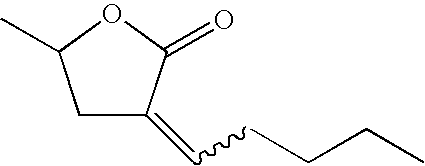
C10H16O2 168 (E,Z)-3-Hexylidene-5-methyl- dihydro-furan-2-one 
C11H18O2 182 (E,Z)-3-Heptylidene-5-methyl- dihydro-furan-2-one 
C12H20O2 196 (E,Z)-3-octylidene-5-methyl- dihydro-furan-2-one 
C13H22O2 210 (E,Z)-3-nonylidene-5-methyl- dihydro-furan-2-one 
C14H24O2 224 (E,Z)-3-decylidene-5-methyl- dihydro-furan-2-one 
C15H26O2 238 (E,Z)-3-(3,5,5-trimethylhexylidene)- 5-methyl-dihydrofuran-2-one 
C14H24O2 224 (E,Z)-3-cyclohexylmethylidene-5- methyl-dihydrofuran-2-one 
C12H18O2 194 gamma-octalactone 
C8H14O2 142 gamma-nonalactone 
C9H16O2 156 gamma-decalactone 
C10H18O2 170 gamma-undecalactone 
C11H20O2 184 gamma-dodecalactone 
C12H22O2 198 3-hexyldihydro-furan-2-one 
C10H18O2 170 3-heptyldihydro-furan-2-one 
C11H20O2 184 cis-3-ethyl-5-methyl-dihydro-furan- 2-one 
C7H12O2 128 cis-(3-propyl-5-methyl)-dihydro- furan-2-one 
C8H14O2 142 cis-(3-butyl-5-methyl)-dihydro- furan-2-one 
C9H16O2 156 cis-(3-pentyl-5-methyl)-dihydro- furan-2-one 
C10H18O2 170 cis-3-hexyl-5-methyl-dihydro- furan-2-one 
C11H20O2 184 cis-3-heptyl-5-methyl-dihydro- furan-2-one 
C12H22O2 198 cis-3-octyl-5-methyl-dihydro-furan- 2-one 
C13H24O2 212 cis-3-(3,5,5-trimethylhexyl)-5- methyl-dihydro-furan-2-one 
C14H26O2 226 cis-3-cyclohexylmethyl-5-methyl- dihydro-furan-2-one 
C12H20O2 196 5-methyl-5-hexyl-dihydro-furan- 2-one 
C11H20O2 184 5-methyl-5-octyl-dihydro-furan- 2-one 
C13H24O2 212 Hexahydro-isobenzofuran-1-one 
C8H12O2 140 delta-decalactone 
C10H18O2 170 delta-undecalactone 
C11H20O2 184 delta-dodecalactone 
C12H22O2 198 mixture of 4-hexyl-dihydrofuran-2- one and 3-hexyl-dihydro-furan-2-one 
C10H18O2 170 - Lactone solubilizing agents generally have a kinematic viscosity of less than about 7 centistokes at 40° C. For instance, gamma-undecalactone has kinematic viscosity of 5.4 centistokes and cis-(3-hexyl-5-5-methyl)dihydrofuran-2-one has viscosity of 4.5 centistokes both at 40° C. Lactone solubilizing agents may be available commercially or prepared by methods as described in U.S. provisional patent application Ser. No. 10/910,495 (inventors being P. J. Fagan and C. J. Brandenburg), filed Aug. 3, 2004, incorporated herein by reference.
- Aryl ether solubilizing agents of the present invention further comprise aryl ethers represented by the formula R1OR2, wherein: R1 is selected from aryl hydrocarbon radicals having from 6 to 12 carbon atoms; R2 is selected from aliphatic hydrocarbon radicals having from 1 to 4 carbon atoms; and wherein said aryl ethers have a molecular weight of from about 100 to about 150 atomic mass units. Representative R1 aryl radicals in the general formula R1OR2 include phenyl, biphenyl, cumenyl, mesityl, tolyl, xylyl, naphthyl and pyridyl. Representative R2 aliphatic hydrocarbon radicals in the general formula R1OR2 include methyl, ethyl, propyl, isopropyl, butyl, isobutyl, sec-butyl and tert-butyl. Representative aromatic ether solubilizing agents include but are not limited to: methyl phenyl ether (anisole), 1,3-dimethyoxybenzene, ethyl phenyl ether and butyl phenyl ether.
- Fluoroether solubilizing agents of the present invention comprise those represented by the general formula R1OCF2CF2H, wherein R1 is selected from aliphatic and alicyclic hydrocarbon radicals having from about 5 to about 15 carbon atoms, preferably primary, linear, saturated, alkyl radicals. Representative fluoroether solubilizing agents include but are not limited to: C8H17OCF2CF2H and C6H13OCF2CF2H. It should be noted that if the refrigerant is a fluoroether, then the solubilizing agent may not be the same fluoroether.
- 1,1,1-Trifluoroalkane solubilizing agents of the present invention comprise 1,1,1-trifluoroalkanes represented by the general formula CF3R1, wherein R1 is selected from aliphatic and alicyclic hydrocarbon radicals having from about 5 to about 15 carbon atoms, preferably primary, linear, saturated, alkyl radicals. Representative 1,1,1-trifluoroalkane solubilizing agents include but are not limited to: 1,1,1-trifluorohexane and 1,1,1-trifluorododecane.
- Solubilizing agents of the present invention may be present as a single compound, or may be present as a mixture of more than one solubilizing agent. Mixtures of solubilizing agents may contain two solubilizing agents from the same class of compounds, say two lactones, or two solubilizing agents from two different classes, such as a lactone and a polyoxyalkylene glycol ether.
- In the present compositions comprising refrigerant and UV fluorescent dye, from about 0.001 weight percent to about 1.0 weight percent of the composition is UV dye, preferably from about 0.005 weight percent to about 0.5 weight percent, and most preferably from 0.01 weight percent to about 0.25 weight percent.
- Solubility of these UV fluorescent dyes in refrigerants may be poor. Therefore, methods for introducing these dyes into the refrigeration or air conditioning apparatus have been awkward, costly and time consuming. U.S. Pat. No. RE-36,951 describes a method, which utilizes a dye powder, solid pellet or slurry of dye that may be inserted into a component of the refrigeration or air conditioning apparatus. As refrigerant and lubricant are circulated through the apparatus, the dye is dissolved or dispersed and carried throughout the apparatus. Numerous other methods for introducing dye into a refrigeration or air conditioning apparatus are described in the literature.
- Ideally, the UV fluorescent dye could be dissolved in the refrigerant itself thereby not requiring any specialized method for introduction to the refrigeration or air conditioning apparatus. The present invention relates to compositions including UV fluorescent dye, which may be introduced into the system directly in the refrigerant. The inventive compositions will allow the storage and transport of dye-containing refrigerant even at low temperatures while maintaining the dye in solution.
- In the present compositions comprising refrigerant, UV fluorescent dye and solubilizing agent, from about 1 to about 50 weight percent, preferably from about 2 to about 25 weight percent, and most preferably from about 5 to about 15 weight percent of the combined composition is solubilizing agent in the refrigerant. In the compositions of the present invention the UV fluorescent dye is present in a concentration from about 0.001 weight percent to about 1.0 weight percent in the refrigerant, preferably from 0.005 weight percent to about 0.5 weight percent, and most preferably from 0.01 weight percent to about 0.25 weight percent.
- The compositions of the present invention may further comprise about 0.01 weight percent to about 5 weight percent of a thermal stabilizer such as nitromethane.
- Optionally, commonly used refrigeration system additives may optionally be added, as desired, to compositions of the present invention in order to enhance performance and system stability. These additives are known within the field of refrigeration, and include, but are not limited to, anti wear agents, extreme pressure lubricants, corrosion and oxidation inhibitors, metal surface deactivators, free radical scavengers, and foam control agents. In general, these additives are present in the inventive compositions in small amounts relative to the overall composition. Typically concentrations of from less than about 0.1 weight percent to as much as about 3 weight percent of each additive are used. These additives are selected on the basis of the individual system requirements. These additives include members of the triaryl phosphate family of EP (extreme pressure) lubricity additives, such as butylated triphenyl phosphates (BTPP), or other alkylated triaryl phosphate esters, e.g. Syn-0-Ad 8478 from Akzo Chemicals, tricrecyl phosphates and related compounds. Additionally, the metal dialkyl dithiophosphates (e.g. zinc dialkyl dithiophosphate (or ZDDP), Lubrizol 1375 and other members of this family of chemicals may be used in compositions of the present invention. Other antiwear additives include natural product oils and asymmetrical polyhydroxyl lubrication additives, such as Synergol TMS (International Lubricants). Similarly, stabilizers such as anti oxidants, free radical scavengers, and water scavengers may be employed. Compounds in this category can include, but are not limited to, butylated hydroxy toluene (BHT) and epoxides.
- Solubilizing agents-such as ketones may have an objectionable odor, which can be masked by addition of an odor masking agent or fragrance. Typical examples of odor masking agents or fragrances may include Evergreen, Fresh Lemon, Cherry, Cinnamon, Peppermint, Floral or Orange Peel or sold by Intercontinental Fragrance, as well as d-limonene and pinene. Such odor masking agents may be used at concentrations of from about 0.001% to as much as about 15% by weight based on the combined weight of odor masking agent and solubilizing agent.
- The present invention further relates to a method of using the refrigerant or heat transfer fluid compositions further comprising ultraviolet fluorescent dye, and optionally, solubilizing agent, in refrigeration or air conditioning apparatus. The method comprises introducing the refrigerant or heat transfer fluid composition into the refrigeration or air conditioning apparatus. This may be done by dissolving the UV fluorescent dye in the refrigerant or heat transfer fluid composition in the presence of a solubilizing agent and introducing the combination into the apparatus. Alternatively, this may be done by combining solubilizing agent and and UV fluorescent dye and introducing said combination into refrigeration or air conditioning apparatus containing refrigerant and/or heat transfer fluid. The resulting composition is may be used in the refrigeration or air conditioning apparatus.
- The present invention further relates to a method of using the refrigerant or heat transfer fluid compositions comprising ultraviolet fluorescent dye to detect leaks. The presence of the dye in the compostions allows for detection of leaking refrigerant in the refrigeration or air conditioning apparatus. Leak detection helps to address, resolve or prevent inefficient operation of the apparatus or system or equipment failure. Leak detection also helps one contain chemicals used in the operation of the apparatus.
- The method comprises providing the composition comprising refrigerant, ultra-violet fluorescent dye as described herein, and optionally, a solubilizing agent as described herein, to refrigeration and air conditioning apparatus and employing a sutiable means for detecting the UV fluorescent dye-containing refrigerant. Suitable means for detecting the dye include, but are not limited to, ultra-violet lamp, often referred to as a “black light” or “blue light”. Such ultra-violet lamps are commercially available from numerous sources specifically designed for this purpose. Once the ultra-violet fluorescent dye containing composition has been introduced to the refrigeration or air conditioning apparatus and has been allowed to circulate throughout the system, a leak can be found by shining said ultra-violet lamp on the apparatus and observing the fluorescence of the dye in the vicinity of any leak point.
- The present invention further relates to a method of using the compositions of the present invention for producing refrigeration or heat, wherein the method comprises producing refrigeration by evaporating said composition in the vicinity of a body to be cooled and thereafter condensing said composition; or producing heat by condensing the said composition in the vicinity of the body to be heated and thereafter evaporating said composition.
- Mechanical refrigeration is primarily an application of thermodynamics wherein a cooling medium, such as a refrigerant, goes through a cycle so that it can be recovered for reuse. Commonly used cycles include vapor-compression, absorption, steam-jet or steam-ejector, and air.
- Vapor-compression refrigeration systems include an evaporator, a compressor, a condenser, and an expansion device. A vapor-compression cycle re-uses refrigerant in multiple steps producing a cooling effect in one step and a heating effect in a different step. The cycle can be described simply as follows. Liquid refrigerant enters an evaporator through an expansion device, and the liquid refrigerant boils in the evaporator at a low temperature to form a gas and produce cooling. The low-pressure gas enters a compressor where the gas is compressed to raise its pressure and temperature. The higher-pressure (compressed) gaseous refrigerant then enters the condenser in which the refrigerant condenses and discharges its heat to the environment. The refrigerant returns to the expansion device through which the liquid expands from the higher-pressure level in the condenser to the low-pressure level in the evaporator, thus repeating the cycle.
- There are various types of compressors that may be used in refrigeration applications. Compressors can be generally classified as reciprocating, rotary, jet, centrifugal, scroll, screw or axial-flow, depending on the mechanical means to compress the fluid, or as positive-displacement (e.g., reciprocating, scroll or screw) or dynamic (e.g., centrifugal or jet), depending on how the mechanical elements act on the fluid to be compressed.
- Either positive displacement or dynamic compressors may be used in the present inventive process. A centrifugal type compressor is the preferred equipment for the present refrigerant compositions.
- A centrifugal compressor uses rotating elements to accelerate the refrigerant radially, and typically includes an impeller and diffuser housed in a casing. Centrifugal compressors usually take fluid in at an impeller eye, or central inlet of a circulating impeller, and accelerate it radially outward. Some static pressure rise occurs in the impeller, but most of the pressure rise occurs in the diffuser section of the casing, where velocity is converted to static pressure. Each impeller-diffuser set is a stage of the compressor. Centrifugal compressors are built with from 1 to 12 or more stages, depending on the final pressure desired and the volume of refrigerant to be handled.
- The pressure ratio, or compression ratio, of a compressor is the ratio of absolute discharge pressure to the absolute inlet pressure. Pressure delivered by a centrifugal compressor is practically constant over a relatively wide range of capacities.
- Positive displacement compressors draw vapor into a chamber, and the chamber decreases in volume to compress the vapor. After being compressed, the vapor is forced-from the chamber by further decreasing the volume of the chamber to zero or nearly zero. A positive displacement compressor can build up a pressure, which is limited only by the volumetric efficiency and the strength of the parts to withstand the pressure.
- Unlike a positive displacement compressor, a centrifugal compressor depends entirely on the centrifugal force of the high-speed impeller to compress the vapor passing through the impeller. There is no positive displacement, but rather what is called dynamic-compression.
- The pressure a centrifugal compressor can develop depends on the tip speed of the impeller. Tip speed is the speed of the impeller measured at its tip and is related to the diameter of the impeller and its revolutions per minute. The capacity of the centrifugal compressor is determined by the size of the passages through the impeller. This makes the size of the compressor more dependent on the pressure required than the capacity.
- Because of its high-speed operation, a centrifugal compressor is fundamentally a high volume, low-pressure machine. A centrifugal compressor works best with a low-pressure refrigerant, such as trichlorofluoromethane (CFC-11) or 1,2,2-trichlorotrifluoroethane (CFC-113).
- Large centrifugal compressors typically operate at 3000 to 7000 revolutions per minute (rpm). Small turbine centrifugal compressors are designed for high speeds, from about 40,000 to about 70,000 (rpm), and have small impeller sizes, typically less than 0.15 meters.
- A multi-stage impeller may be used in a centrifugal compressor to improve compressor efficiency thus requiring less power in use. For a two-stage system, in operation, the discharge of the first stage impeller goes to the suction intake of a second impeller. Both impellers may operate by use of a single shaft (or axle). Each stage can build up a compression ratio of about 4 to 1; that is, the absolute discharge pressure can be four times the absolute suction pressure. An example of a two-stage centrifugal compressor system, in this case for automotive applications, is described in U.S. Pat. No. 5,065,990, incorporated herein by reference.
- The fluoroether refrigerant or heat transfer fluid compositions are selected from the group consisting of:
- 2-difluoromethoxy-1,1,1-trifluoroethane;
- 1,1-difluoro-2-trifluoromethoxyethane;
- 1,1,1,2,2-pentafluoro-2-methoxyethane;
- 2-difluoromethoxy-1,1,1,2-tetrafluoroethane;
- 1-difluoromethoxy-1,1,2,2-tetrafluoroethane;
- 2-methoxy-1,1,1-trifluoroethane;
- 1,1,1,2,2-pentafluoro-2-(2,2,2-trifluoroethoxy)ethane;
- 1-(2,2,2-trifluoroethoxy)-1,1,2,2-tetrafluoroethane;
- 1,1,2,2,3,3-hexafluoro-3-methoxypropane;
- 1-(1,1-difluoroethoxy)-1,1,2,2-tetrafluoroethane;
- 3-(difluoromethoxy)-1,1,2,2-tetrafluoropropane;
- 1-(difluoromethoxy)-1,1,2-trifluoroethane;
- 1-(difluoromethoxy)-1,2,2-trifluoroethane;
- 2-fluoromethoxy-1,1,1,2-tetrafluoroethane;
- 1-methoxy-1,1,2,2-tetrafluoroethane;
- 2-methoxy-1,1,1,2-tetrafluoroethane;
- 1-difluoromethoxy-2,2-difluoroethane;
- 2-methoxy-1,1,2-trifluoroethane;
- 1,1-difluoro-2-methoxyethane;
- 1,1′-oxybis(1,2,2,2-tetrafluoro)ethane;
- 2-(difluroomethoxy)-1,1,1,3,3,3-hexafluoropropane;
- 3-(difluoromethoxy)-1,1,1,2,2,3-hexafluoropropane;
- 1,1,1,2,2,3,3-heptafluoro-3-methoxypropane;
- 1,1,3,3-tetrafluoro-1-(trifluoromethoxy)propane;
- 1-(2,2-difluoroethoxy)-1,1,2,2,2-pentafluoroethane;
- 3-(difluoromethoxy)-1,1,1,2,2-pentafluoropropane;
- 1,1,2,2-tetrafluoro-3-(trifluoromethoxy)propane;
- 1,1,1,2-tetrafluoro-2-(2,2,2-trifluoroethoxy)ethane;
- 1,1,1,3,3,3-hexafluoro-2-(fluoromethoxy)propane;
- 1,1,2,2-tetrafluoro-1-(1,2,2-trifluoroethoxy)ethane;
- 1,1,2-trifluoro-1-methoxy-2-(trifluoromethoxy)ethane;
- 1,1,1,2,3,3-hexafluoro-3-methoxypropane;
- 1,1,1,3,3,3-hexafluoro-2-methoxypropane;
- 2-(difluoromethoxy)-1,1,1-trifluoropropane;
- 1,1,1,2,2-pentafluoro-3-methoxypropane;
- 2-ethoxy-1,1,1,2-tetrafluoroethane;
- 1-ethoxy-1,1,2,2-tetrafluoroethane;
- 1-(trifluoromethoxy)propane;
- 1,1,1-trifluoro-2-ethoxyethane;
- 1,1,1-trifluoro-3-methoxypropane;
- 1,1,1-trifluoro-2-methoxypropane;
- 1-ethoxy-1,2,2-trifluoroethane;
- 1,1,1,2,2,3,3-heptafluoro-3-(1,2,2,2-tetrafluoroethoxy)propane;
- 1,1,1,2,3,3-hexafluoro-3-(pentafluoroethoxy)propane;
- 2-ethoxy-1,1,1,2,3,3,3-heptafluoro propane;
- 3-ethoxy-1,1,1,2,2,3,3-heptafluoropropane;
- 2-ethoxy-1,1,1,3,3,3-hexafluoropropane;
- 1-(1,1,2,2-tetrafluoroethoxy)propane;
- 3-ethoxy-1,1,2,2-tetrafluoropropane;
- 2-(1,1,2,2-tetrafluoroethoxy)propane;
- 2,2,3,4,5,5-hexafluorotetrahydrofuran;
- 2,3-difluoro-4-(trifluoromethyl)oxetane;
- mixtures comprising 1,1,1,2,2,3,3,4,4-nonafluoro-4-methoxybutane
- and 2-(difluoromethoxymethyl)-1,1,1,2,3,3,3-heptafluoropropane (C4F9OCH3); and
- mixtures comprising 1-ethoxy-1,1,2,2,3,3,4,4,4-nonafluorobutane and 2-(ethoxydifluoromethyl)-1,1,1,2,3,3,3-heptafluoropropane (C4F9OC2H5).
These above-listed compositions are also suitable for use in two-stage centrifugal compressor apparatus. - The compositions of the present invention may be used in stationary air-conditioning, heat pumps or mobile air-conditioning and refrigeration apparatus. Stationary air conditioning and heat pump applications include window, ductless, ducted, packaged terminal, chillers and commercial, including packaged rooftop. Refrigeration applications include domestic or home refrigerators and freezers, ice machines, self-contained coolers and freezers, walk-in coolers and freezers and transport refrigeration systems.
- The compositions of the present invention may additionally be used in air-conditioning, heating and refrigeration apparatus that employ fin and tube heat exchangers, microchannel heat exchangers and vertical or horizontal single pass tube or plate type heat exchangers.
- Conventional microchannel heat exchangers may not be ideal for the low pressure refrigerant compositions of the present invention. The low operating pressure and density result in high flow velocities and high frictional losses in all components. In these cases, the evaporator design may be modified. Rather than several microchannel slabs connected in series (with respect to the refrigerant path) a single slab/single pass heat exchanger arrangement may be used. Therefore, a preferred heat exchanger for the low pressure refrigerants of the present invention is a single slab/single pass heat exchanger.
- In addition to two-stage compressor apparatus, the fluoroether compositons of the present invention are suitable for use in refrigeration or air conditioning apparatus employing a single slab/single pass heat exchanger. These compositions are selected from the group consisting of:
- 2-difluoromethoxy-1,1,1-trifluoroethane;
- 1,1-difluoro-2-trifluoromethoxyethane;
- 1,1,1,2,2-pentafluoro-2-methoxyethane;
- 2-difluoromethoxy-1,1,1,2-tetrafluoroethane;
- 1-difluoromethoxy-1,1,2,2-tetrafluoroethane;
- 2-methoxy-1,1,1-trifluoroethane;
- 1,1,1,2,2-pentafluoro-2-(2,2,2-trifluoroethoxy)ethane;
- 1-(2,2,2-trifluoroethoxy)-1,1,2,2-tetrafluoroethane;
- 1,1,2,2,3,3-hexafluoro-3-methoxypropane;
- 1-(1,1-difluoroethoxy)-1,1,2,2-tetrafluoroethane;
- 3-(difluoromethoxy)-1,1,2,2-tetrafluoropropane;
- 1-(difluoromethoxy)-1,1,2-trifluoroethane;
- 1-(difluoromethoxy)-1,2,2-trifluoroethane;
- 2-fluoromethoxy-1,1,1,2-tetrafluoroethane;
- 1-methoxy-1,1,2,2-tetrafluoroethane;
- 2-methoxy-1,1,1,2-tetrafluoroethane;
- 1-difluoromethoxy-2,2-difluoroethane;
- 2-methoxy-1,1,2-trifluoroethane;
- 1,1-difluoro-2-methoxyethane;
- 1,1′-oxybis(1,2,2,2-tetrafluoro)ethane;
- 2-(difluroomethoxy)-1,1,1,3,3,3-hexafluoropropane;
- 3-(difluoromethoxy)-1,1,1,2,2,3-hexafluoropropane;
- 1,1,1,2,2,3,3-heptafluoro-3-methoxypropane;
- 1,1,3,3-tetrafluoro-1-(trifluoromethoxy)propane;
- 1-(2,2-difluoroethoxy)-1,1,2,2,2-pentafluoroethane;
- 3-(difluoromethoxy)-1,1,1,2,2-pentafluoropropane;
- 1,1,2,2-tetrafluoro-3-(trifluoromethoxy)propane;
- 1,1,1,2-tetrafluoro-2-(2,2,2-trifluoroethoxy)ethane;
- 1,1,1,3,3,3-hexafluoro-2-(fluoromethoxy)propane;
- 1,1,2,2-tetrafluoro-1-(1,2,2-trifluoroethoxy)ethane;
- 1,1,2-trifluoro-1-methoxy-2-(trifluoromethoxy)ethane;
- 1,1,1,2,3,3-hexafluoro-3-methoxypropane;
- 1,1,1,3,3,3-hexafluoro-2-methoxypropane;
- 2-(difluoromethoxy)-1,1,1-trifluoropropane;
- 1,1,1,2,2-pentafluoro-3-methoxypropane;
- 2-ethoxy-1,1,1,2-tetrafluoroethane;
- 1,1-ethoxy-1,1,2,2-tetrafluoroethane;
- 1-(trifluoromethoxy)propane;
- 1,1,1-trifluoro-2-ethoxyethane;
- 1,1,1-trifluoro-3-methoxypropane;
- 1,1,1-trifluoro-2-methoxypropane;
- 1-ethoxy-1,2,2-trifluoroethane;
- 1,1,1,2,2,3,3-heptafluoro-3-(1,2,2,2-tetrafluoroethoxy)propane;
- 1,1,1,2,3,3-hexafluoro-3-(pentafluoroethoxy)propane;
- 2-ethoxy-1,1,1,2,3,3,3-heptafluoropropane;
- 3-ethoxy-1,1,1,2,2,3,3-heptafluoropropane;
- 2-ethoxy-1,1,1,3,3,3-hexafluoropropane;
- 1-(1,1,2,2-tetrafluoroethoxy)propane;
- 3-ethoxy-1,1,2,2-tetrafluoropropane;
- 2-(1,1,2,2-tetrafluoroethoxy)propane;
- 2,2,3,4,5,5-hexafluorotetrahydrofuran;
- 2,3-difluoro-4-(trifluoromethyl)oxetane;
- mixtures comprising 1,1,1,2,2,3,3,4,4-nonafluoro-4-methoxybutane and 2-(difluoromethoxymethyl)-1,1,1,2,3,3,3-heptafluoropropane (C4F9OCH3); and
- mixtures comprising 1-ethoxy-1,1,2,2,3,3,4,4,4-nonafluorobutane and 2-(ethoxydifluoromethyl)-1,1,1,2,3,3,3-heptafluoropropane (C4F9OC2H5).
- The compositions of the present invention are particularly useful in small turbine centrifugal compressors, which can be used in auto and window air conditioning or heat pump as well as other applications. These high efficiency miniature centrifugal compressors may be driven by an electric motor and can therefore be operated independently of the engine speed. A constant compressor speed allows the system to provide a relatively constant cooling capacity at all engine speeds. This provides an opportunity for efficiency improvements especially at higher engine speeds as compared to a conventional R-134a automobile air-conditioning system. When the cycling operation of conventional systems at high driving speeds is taken into account, the advantage of these low pressure systems becomes even greater.
- Some of the low pressure refrigerant fluids of the present invention may be suitable as drop-in replacements for CFC-113 in existing centrifugal equipment.
- The present invention relates to a process for producing refrigeration comprising evaporating the compositions of the present invention in the vicinity of a body to be cooled, and thereafter condensing said compositions.
- The present invention further relates to a process for producing heat comprising condensing the compositions of the present invention in the vicinity of a body to be heated, and thereafter evaporating said compositions.
- The present invention further relates to a process for transfer of heat from a heat source to a heat sink wherein the compositions of the present invention serve as heat transfer fluids. Said process for heat transfer comprises transferring the compositions of the present invention from a heat source to a heat sink.
- Heat transfer fluids are utilized to transfer, move or remove heat from one space, location, object or body to a different space, location, object or body by radiation, conduction, or convection. A heat transfer fluid may function as a secondary coolant by providing means of transfer for cooling (or heating) from a remote refrigeration (or heating) system. In some systems, the heat transfer fluid may remain in a constant state throughout the transfer process (i.e., not evaporate or condense). Alternatively, evaporative cooling processes may utilize heat transfer fluids as well.
- A heat source may be defined as any space, location, object or body from which it is desirable to transfer, move or remove heat. Examples of heat sources may be spaces (open or enclosed) requiring refrigeration or cooling, such as refrigerator or freezer cases in a supermarket, building spaces requiring air conditioning, or the passenger compartment of an automobile requiring air conditioning. A heat sink may be defined as any space, location, object or body capable of absorbing heat. A vapor compression refrigeration system is one example of such a heat sink.
- Tip speed can be estimated by making some fundamental relationships for refrigeration equipment that use centrifugal compressors. The torque an impeller ideally imparts to a gas is defined as
T=m*(v 2 *r 2 −v 1 *r 1) Equation 1
where -
- T=torque, N*m
- m=mass rate of flow, kg/s
- v2=tangential velocity of refrigerant leaving impeller (tip speed), m/s
- r2=radius of exit impeller, m
- v1=tangential velocity of refrigerant entering impeller, m/s
- r1=radius of inlet of impeller, m
- Assuming the refrigerant enters the impeller in an essentially radial direction, the tangential component of the velocity v1=0, therefore
T=m*v 2 *r 2 Equation 2 - The power required at the shaft is the product of the torque and the rotative speed
P=T*w Equation 3
where -
- P=power, W
- w=rotative speed, rez/s therefore,
P=T*w=m*v 2 *r 2 *w Equation 4
- At low refrigerant flow rates, the tip speed of the impeller and the tangential velocity of the refrigerant are nearly identical; therefore
r 2 *w=v 2 Equation 5
and
P=m*v 2 *v 2 Equation 6 - Another expression for ideal power is the product of the mass rate of flow and the isentropic work of compression,
P=m*H i*(1000J/kJ) Equation 7
where -
- Hi=Difference in enthalpy of the refrigerant from a saturated vapor at the evaporating conditions to saturated condensing conditions, kJ/kg.
- Combining the two expressions Equation 6 and 7 produces,
v 2 *v 2=1000*H i Equation 8 - Although Equation 8 is based on some fundamental assumptions, it provides a good estimate of the tip speed of the impeller and provides an important way to compare tip speeds of refrigerants.
- Table 3 below shows theoretical tip speeds that are calculated for 1,2,2-trichlorotrifluoroethane (CFC-113) and compositions of the present invention. The conditions assumed for this comparison are:
Evaporator temperature 40.0° F. (4.4° C.) Condenser temperature 110.0° F. (43.3° C.) Liquid subcool temperature 10.0° F. (5.5° C.) Return gas temperature 75.0° F. (23.8° C.) Compressor efficiency is 70% - These are typical conditions under which small turbine centrifugal compressors perform.
TABLE 3 Hi Hi*0.7 Hi*0.7 V2 V2 rel Refrigerant Btu/lb Btu/lb KJ/Kg m/s to CFC-113 CFC-113 10.92 7.6 17.8 133.3 n/a C4F9OC2H5 13.73 9.6 22.4 149.5 112% C4F9OCH3 12.80 9.0 20.8 144.4 108% HFOC-245caEαβ 12.84 9.0 20.9 144.6 108% HFOC-245eaE 12.56 8.8 20.5 143.0 107% HFOC-245ebEβγ 12.89 9.0 21.0 144.9 109% HFOC-254cbEβγ 13.75 9.6 22.4 149.6 112% HFOC-254ebEβγ 13.77 9.6 22.4 149.7 112% HFOC-254faE 13.82 9.7 22.5 150.0 113% HFOC-263ebEβγ 15.09 10.6 24.6 156.7 118% HFOC-272fbEβγ 17.12 12.0 27.9 167.0 125% HFOC-347mccEγδ 12.62 8.8 20.5 143.3 108% HFOC-347mcfEβγ 12.65 8.9 20.6 143.5 108% HFOC-347mcfEγδ 12.66 8.9 20.6 143.6 108% HFOC-347mefEβγ 12.83 9.0 20.9 144.5 108% HFOC-347mfcEαβ 12.66 8.9 20.6 143.6 108% HFOC-347mmzEβγ 12.83 9.0 20.9 144.5 108% HFOC-347pceEβγ 12.51 8.8 20.4 142.7 107% HFOC-356mecE2αβγδ 13.51 9.5 22.0 148.3 111% HFOC-356mecEγδ 13.48 9.4 21.9 148.1 111% HFOC-356mmzEβγ 13.41 9.4 21.8 147.8 111% HFOC-356pccEγδ 13.61 9.5 22.2 148.9 112% HFOC-356pcfEβγ 13.46 9.4 21.9 148.0 111% HFOC-356pcfEγδ 13.48 9.4 21.9 148.1 111% HFOC-365mcEγδ 14.46 10.1 23.5 153.4 115% HFOC-365mpzEβγ 14.01 9.8 22.8 151.0 113% HFOC-374mefEβγ 15.46 10.8 25.2 158.7 119% HFOC-374pcEβγ 15.43 10.8 25.1 158.5 119% HFOC-374pcEβγ 15.43 10.8 25.1 158.5 119% HFOC-383mEβγ 17.01 11.9 27.7 166.4 125% HFOC-383mEγδ 17.09 12.0 27.8 166.8 125% HFOC-383mzEαβ 16.65 11.7 27.1 164.6 124% HFOC-383peEβγ 16.46 11.5 26.8 163.7 123% HFOC-467mccEγδ 13.91 9.7 22.6 150.5 113% HFOC-467mmyEβγ 13.81 9.7 22.5 150.0 112% HFOC-476mmzEβγ 14.63 10.2 23.8 154.3 116% HFOC-494pcEβγ 16.73 11.7 27.2 165.0 124% HFOC-c345mzEαβ 13.40 9.4 21.8 147.7 111% - The Example shows that compounds of the present invention have tip speeds within about +/−30 percent of CFC-113 and would be effective replacements for CFC-113 with minimal compressor design changes. Many compositions have tip speeds within about +15 percent of CFC-113.
- Table 4 shows the performance of various refrigerants compared to CFC-113. The data are based on the following conditions.
Evaporator temperature 40.0° F. (4.4° C.) Condenser temperature 110.0° F. (43.3° C.) Subcool temperature 10.0° F. (5.5° C.) Return gas temperature 75.0° F. (23.8° C.) Compressor efficiency is 70% -
TABLE 4 Compr Compr Evap Evap Cond Cond Disch Disch Pres Pres Pres Pres Temp Temp Capacity Capacity Refrigerant (Psia) (kPa) (Psia) (kPa) (F.) (C.) COP (Btu/min) (kW) CFC-113 2.7 19 12.8 88 156.3 69.1 4.18 14.8 0.26 C4F9OC2H5 0.8 5 5.1 35 128.9 53.8 3.90 5.5 0.10 C4F9OCH3 1.5 10 8.3 57 131.3 55.2 3.93 9.5 0.17 HFOC-245caEαβ 3.4 23 16.5 113 159.2 70.7 4.18 21.6 0.38 HFOC-245eaE 1.9 13 10.3 71 168.0 75.6 4.25 13.3 0.23 HFOC-245ebEβγ 3.0 20 14.8 102 160.1 71.2 4.20 19.3 0.34 HFOC-254cbEβγ 3.8 26 18.0 124 160.9 71.6 4.20 24.1 0.42 HFOC-254ebEβγ 3.7 26 17.5 120 161.1 71.7 4.21 23.4 0.41 HFOC-254faE 1.7 12 9.5 65 172.2 77.9 4.28 12.2 0.21 HFOC-263ebEβγ 1.7 12 9.2 64 175.9 79.9 4.30 12.1 0.21 HFOC-272fbEβγ 2.3 16 12.0 83 176.8 80.4 4.30 16.1 0.28 HFOC-347mccEγδ 4.5 31 20.4 141 136.5 58.1 3.95 25.4 0.44 HFOC-347mcfEβγ 2.7 18 13.8 95 142.0 61.1 4.04 16.9 0.30 HFOC-347mcfEγδ 2.6 18 13.6 94 142.1 61.2 4.04 16.6 0.29 HFOC-347mefEβγ 1.5 10 8.4 58 145.5 63.1 4.11 10.2 0.18 HFOC-347mfcEαβ 2.6 18 13.5 93 142.2 61.2 4.04 16.5 0.29 HFOC-347mmzEβγ 1.5 11 8.8 60 145.2 62.9 4.10 10.6 0.18 HFOC-347pceEβγ 1.2 8 7.3 50 149.5 65.3 4.15 8.6 0.15 HFOC-356mecE2αβγδ 1.5 10 8.7 60 143.8 62.1 4.09 10.3 0.18 HFOC-356mecEγδ 1.7 12 9.4 65 145.9 63.3 4.12 11.6 0.20 HFOC-356mmzEβγ 2.3 16 11.6 80 144.3 62.4 4.09 14.5 0.25 HFOC-356pccEγδ 1.1 7 6.1 42 149.1 65.1 4.17 7.4 0.13 HFOC-356pcfEβγ 0.6 4 3.9 27 157.6 69.8 4.22 4.5 0.08 HFOC-356pcfEγδ 0.8 6 5.2 36 154.0 67.8 4.2 6.1 0.11 HFOC-365mcEγδ 2.5 17 12.7 87 145.2 62.9 4.10 16.0 0.28 HFOC-365mpzEβγ 2.4 17 12.5 86 148.5 64.7 4.13 15.7 0.27 HFOC-374mefEβγ 1.6 11 8.7 60 153.3 67.4 4.19 10.9 0.19 HFOC-374pcEβγ 1.7 12 9.3 64 152.7 67.1 4.18 11.7 0.21 HFOC-374pcEβγ 1.7 12 9.3 64 152.7 67.1 4.18 11.7 0.21 HFOC-383mEβγ 2.2 15 11.6 80 152.9 67.2 4.17 14.8 0.26 HFOC-383mEγδ 1.8 12 9.7 67 154.4 68.0 4.19 12.3 0.22 HFOC-383mzEαβ 2.5 17 12.4 86 152.0 66.7 4.18 16.2 0.28 HFOC-383peEβγ 2.0 14 10.7 74 157.3 69.6 4.21 13.6 0.24 HFOC-467mccEγδ 2.1 14 11.2 77 133.2 56.2 3.95 13.1 0.23 HFOC-467mmyEβγ 2.7 19 13.8 95 132.0 55.6 3.91 16.3 0.29 HFOC-476mmzEβγ 1.2 8 6.9 48 139.5 59.7 4.06 8.1 0.14 HFOC-494pcEβγ 0.8 6 5.2 36 146.7 63.7 4.15 6.1 0.11 HFOC-c345mzEαβ 1.6 11 8.4 58 154.7 68.2 4.2 10.7 0.19
Data show the compositions of the present invention have evaporator and condenser pressures similar to CFC-113. Some compositions also have higher capacity or energy efficiency (COP) than CFC-113.
Claims (16)
1. A fluoroether refrigerant or heat transfer fluid composition, said composition selected from the group consisting of:
2-difluoromethoxy-1,1,1-trifluoroethane;
1,1-difluoro-2-trifluoromethoxyethane;
1,1,1,2,2-pentafluoro-2-methoxyethane;
2-difluoromethoxy-1,1,1,2-tetrafluoroethane;
1-difluoromethoxy-1,1,2,2-tetrafluoroethane;
2-methoxy-1,1,1-trifluoroethane;
1,1,1,2,2-pentafluoro-2-(2,2,2-trifluoroethoxy)ethane;
1-(2,2,2-trifluoroethoxy)-1,1,2,2-tetrafluoroethane;
1,1,2,2,3,3-hexafluoro-3-methoxypropane;
1-(1,1-difluoroethoxy)-1,1,2,2-tetrafluoroethane;
3-(difluoromethoxy)-1,1,2,2-tetrafluoropropane;
2-fluoromethoxy-1,1,2-tetrafluoroethane;
2-methoxy-1,1,1,2-tetrafluoroethane;
1-difluoromethoxy-2,2-difluoroethane;
2-methoxy-1,1,2-trifluoroethane;
1,1-difluoro-2-methoxyethane;
1,1,1,2,2,3,3-heptafluoro-3-methoxypropane;
1,1,3,3-tetrafluoro-1-(trifluoromethoxy)propane;
1-(2,2-difluoroethoxy)-1,1,2,2,2-pentafluoroethane;
1,1,2,2-tetrafluoro-3-(trifluoromethoxy)propane;
1,1,1,2-tetrafluoro-2-(2,2,2-trifluoroethoxy)ethane;
1,1,1,3,3,3-hexafluoro-2-(fluoromethoxy)propane;
1,1,2,2-tetrafluoro-1-(1,2,2-trifluoroethoxy)ethane;
1,1,2-trifluoro-1-methoxy-2-(trifluoromethoxy)ethane;
1,1,1,2,2-pentafluoro-3-methoxypropane;
2-(difluoromethoxy)-1,1,1-trifluoropropane;
1-(trifluoromethoxy)propane;
1,1,1-trifluoro-2-ethoxyethane;
1,1,1-trifluoro-3-methoxypropane;
1,1,1-trifluoro-2-methoxypropane;
1-ethoxy-1,2,2-trifluoroethane;
1,1,1,2,3,3-hexafluoro-3-(pentafluoroethoxy)propane;
2-ethoxy-1,1,1,3,3,3-hexafluoropropane;
1-(1,1,2,2-tetrafluoroethoxy)propane;
3-ethoxy-1,1,2,2-tetrafluoropropane;
2-(1,1,2,2-tetrafluoroethoxy)propane;
2,2,3,4,5,5-hexafluorotetrahydrofuran;
1-(1,1,2,2-tetrafluoroethoxy)propane;
3-ethoxy-1,1,2,2-tetrafluoropropane;
2-(1,1,2,2-tetrafluoroethoxy)propane; and
2,3-difluoro-4-(trifluoromethyl)oxetane.
2. A fluoroether refrigerant or heat transfer fluid composition suitable for use in refrigeration or air conditioning apparatus employing (i) a centrifugal compressor, (ii) a multi-stage centrifugal compressor, or (iii) a single slab/single pass heat exchanger, said composition selected from the group consisting of:
2-difluoromethoxy-1,1,1-trifluoroethane;
1,1-difluoro-2-trifluoromethoxyethane;
1,1,1,2,2-pentafluoro-2-methoxyethane;
2-difluoromethoxy-1,1,1,2-tetrafluoroethane;
1-difluoromethoxy-1,1,2,2-tetrafluoroethane;
2-methoxy-1,1,1-trifluoroethane;
1,1,1,2,2-pentafluoro-2-(2,2,2-trifluoroethoxy)ethane;
1-(2,2,2-trifluoroethoxy)-1,1,2,2-tetrafluoroethane;
1,1,2,2,3,3-hexafluoro-3-methoxypropane;
1-(1,1-difluoroethoxy)-1,1,2,2-tetrafluoroethane;
3-(difluoromethoxy)-1,1,2,2-tetrafluoropropane;
1-(difluoromethoxy)-1,1,2-trifluoroethane;
1-(difluoromethoxy)-1,2,2-trifluoroethane;
2-fluoromethoxy-1,1,1,2-tetrafluoroethane;
2-methoxy-1,1,1,2-tetrafluoroethane;
1-difluoromethoxy-2,2-difluoroethane;
2-methoxy-1,1,2-trifluoroethane;
1,1-difluoro-2-methoxyethane;
1,1,1,2,2,3,3-heptafluoro-3-methoxypropane;
1,1,3,3-tetrafluoro-1-(trifluoromethoxy)propane;
1-(2,2-difluoroethoxy)-1,1,2,2,2-pentafluoroethane;
3-(difluoromethoxy)-1,1,1,2,2-pentafluoropropane;
1,1,2,2-tetrafluoro-3-(trifluoromethoxy)propane;
1,1,1,2-tetrafluoro-2-(2,2,2-trifluoromethoxy)ethane;
1,1,1,3,3,3-hexafluoro-2-(fluoromethoxy)propane;
1,1,2,2-tetrafluoro-1-(1,2,2-trifluoroethoxy)ethane;
1,1,2-trifluoro-1-methoxy-2-(trifluoromethoxy)ethane;
1,1,1,2,3,3-hexafluoro-3-methoxypropane;
1,1,1,3,3,3-hexafluoro-2-methoxypropane;
1,1,1,2,2-pentafluoro-3-methoxypropane;
2-(difluoromethoxy)-1,1,1-trifluoropropane;
2-ethoxy-1,1,1,2-tetrafluoroethane;
1-ethoxy-1,1,2,2-tetrafluoroethane;
1-(trifluoromethoxy)propane;
1,1,1-trifluoro-2-ethoxyethane;
1,1-trifluoro-3-methoxypropane;
1,1,1-trifluoro-2-methoxypropane;
1-ethoxy-1,2,2-trifluoroethane;
1,1,1,2,3,3-hexafluoro-3-(pentafluoroethoxy)propane;
2-ethoxy-1,1,1,2,3,3,3-heptafluoropropane;
3-ethoxy-1,1,1,2,2,3,3-heptafluoropropane;
2-ethoxy-1,1,1,3,3,3-hexafluoropropane;
1-(1,1,2,2-tetrafluoroethoxy)propane;
3-ethoxy-1,1,2,2-tetrafluoropropane;
2-(1,1,2,2-tetrafluoroethoxy)propane;
2,2,3,4,5,5-hexafluorotetrahydrofuran;
2,3-difluoro-4-(trifluoromethyl)oxetane;
1-(1,1,2,2-tetrafluoroethoxy)propane;
3-ethoxy-1,1,2,2-tetrafluoropropane;
2-(1,1,2,2-tetrafluoroethoxy)propane;
2,3-difluoro-4-(trifluoromethyl)oxetane;
mixtures comprising 1,1,1,2,2,3,3,4,4-nonafluoro-4-methoxybutane and 2-(difluoromethoxymethyl)-1,1,1,2,3,3,3-heptafluoropropane (C4F9OCH3); and
mixtures comprising 1-ethoxy-1,1,2,2,3,3,4,4,4-nonafluorobutane and 2-(ethoxydifluoromethyl)-1,1,1,2,3,3,3-heptafluoropropane (C4F9OC2H5).
3. A method of using the composition of claim 2 , said method comprising producing heat or refrigeration in a refrigeration or air conditioning apparatus wherein said apparatus employe a multi-stage centrifugal compressor.
4. A process for producing refrigeration, said process comprising evaporating the composition of claim 1 or 2 in the vicinity of a body to be cooled and thereafter condensing said composition.
5. A process for producing heat, said process comprising condensing the composition of claim 1 or 2 in the vicinity of a body to be cooled and thereafter evaporating said composition.
6. A method of using the composition of claim 1 or 2 for heat transfer, said method comprising transferring the composition from a heat source to a heat sink.
7. The composition of claim 1 said composition further comprising at least one ultra-violet fluorescent dye selected from the group consisting of naphthalimides, perylenes, coumarins, anthracenes, phenanthracenes, xanthenes, thioxanthenes, naphthoxanthenes, fluoresceins, derivatives of said dye and combinations thereof.
8. The composition of claim 2 said composition further comprising at least one ultra-violet fluorescent dye selected from the group consisting of naphthalimides, perylenes, coumarins, anthracenes, phenanthracenes, xanthenes, thioxanthenes, naphthoxanthenes, fluoresceins, derivatives of said dye and combinations thereof.
9. The composition of claim 7 , further comprising at least one solubilizing agent selected from the group consisting of hydrocarbons, dimethylether, polyoxyalkylene glycol ethers, amides, ketones, nitriles, chlorocarbons, esters, lactones, aryl ethers, fluoroethers, and 1,1,1-trifluoroalkanes; and wherein the refrigerant and solubilizing agent are not the same compound.
10. The composition of claim 9 , wherein said solubilizing agent is selected from the group consisting of:

a) polyoxyalkylene glycol ethers represented by the formula R1[(OR2)xOR3]y, wherein: x is an integer from 1 to 3; y is an integer from 1 to 4; R1 is selected from hydrogen and aliphatic hydrocarbon radicals having 1 to 6 carbon atoms and y bonding sites; R2 is selected from aliphatic hydrocarbylene radicals having from 2 to 4 carbon atoms; R3 is selected from hydrogen, and aliphatic and alicyclic hydrocarbon radicals having from 1 to 6 carbon atoms; at least one of R1 and R3 is selected from said hydrocarbon radicals; and wherein said polyoxyalkylene glycol ethers have a molecular weight of from about 100 to about 300 atomic mass units;
b) amides represented by the formulae R1CONR2R3 and cyclo-[R4CON(R5)—], wherein R1, R2, R3 and R5 are independently selected from aliphatic and alicyclic hydrocarbon radicals having from 1 to 12 carbon atoms, and at most one aromatic radical having from 6 to 12 carbon atoms; R4 is selected from aliphatic hydrocarbylene radicals having from 3 to 12 carbon atoms; and wherein said amides have a molecular weight of from about 100 to about 300-atomic mass units;
c) ketones represented by the formula R1COR2, wherein R1 and R2 are independently selected from aliphatic, alicyclic and aryl hydrocarbon radicals having from 1 to 12 carbon atoms, and wherein said ketones have a molecular weight of from about 70 to about 300 atomic mass units;
d) nitriles represented by the formula R1CN, wherein R1 is selected from aliphatic, alicyclic or aryl hydrocarbon radicals having from 5 to 12 carbon atoms, and wherein said nitriles have a molecular weight of from about 90 to about 200 atomic mass units;
e) chlorocarbons represented by the formula RClx, wherein; x is selected from the integers 1 or 2; R is selected from aliphatic and alicyclic hydrocarbon radicals having from 1 to 12 carbon atoms; and wherein said chlorocarbons have a molecular weight of from about 100 to about 200 atomic mass units;
f) aryl ethers represented by the formula R1OR2, wherein: R1 is selected from aryl hydrocarbon radicals having from 6 to 12 carbon atoms; R2 is selected from aliphatic hydrocarbon radicals having from 1 to 4 carbon atoms; and wherein said aryl ethers have a molecular weight of from about 100 to about 150 atomic mass units;
g) 1,1,1-trifluoroalkanes represented by the formula CF3R1, wherein R1 is selected from aliphatic and alicyclic hydrocarbon radicals having from about 5 to about 15 carbon atoms;
i) fluoroethers represented by the formula R1OCF2CF2H, wherein R1 is selected from aliphatic and alicyclic hydrocarbon radicals having from about 5 to about 15 carbon atoms; and
j) lactones represented by structures [B], [C], and [D]:
wherein, R1 through R8 are independently selected from hydrogen, linear, branched, cyclic, bicyclic, saturated and unsaturated hydrocarbyl radicals; and the molecular weight is from about 100 to about 300 atomic mass units; and
k) esters represented by the general formula R1CO2R2, wherein R1 and R2 are independently selected from linear and cyclic, saturated and unsaturated, alkyl and aryl radicals; and wherein said esters have a molecular weight of from about 80 to about 550 atomic mass units.
11. A method of using the composition of claim 9 , said method comprising: introducing the composition into a compression refrigeration or air conditioning apparatus by (i) dissolving the ultraviolet fluorescent dye in the refrigerant or heat transfer fluid composition in the presence of the solubilizing agent, and introducing the combination into said apparatus; or (ii) combining solubilizing agent and ultra-violet fluorescent dye and introducing said composition into said apparatus containing refrigerant or heat transfer fluid composition.
12. A method of using the composition of claim 7 or 9, said method comprising providing said composition to said apparatus, and providing a suitable means for detecting said composition at a leak point or in the vicinity of said apparatus.
13. A method of using the composition of claim 7 or 9, said method comprising:
(i) producing refrigeration by evaporating said composition in the vicinity of a body to be cooled and thereafter condensing said composition; or
(ii) producing heat by condensing said composition in the vicinity of a body to be heated and thereafter evaporating said composition.
14. The composition of claim 1 or 2 further comprising a thermal stabilizer or odor masking agent.
15. The composition of claim 14 wherein said thermal stabilizer is nitromethane.
16. The method of claim 3 wherein said multi-stage centrifugal compressor is a two-stage centrifugal compressor.
Priority Applications (11)
| Application Number | Priority Date | Filing Date | Title |
|---|---|---|---|
| US11/014,003 US20050151110A1 (en) | 2004-01-14 | 2004-12-16 | Fluoroether refrigerant compositions and uses thereof |
| PCT/US2005/001512 WO2005067559A2 (en) | 2004-01-14 | 2005-01-12 | Fluoroether refrigerant compositions and uses thereof |
| JP2006549687A JP2007517977A (en) | 2004-01-14 | 2005-01-12 | Fluoroether refrigerant composition and use thereof |
| EP05711560A EP1706469A2 (en) | 2004-01-14 | 2005-01-12 | Fluoroether refrigerant compositions and uses thereof |
| CA002552643A CA2552643A1 (en) | 2004-01-14 | 2005-01-12 | Fluoroether refrigerant compositions and uses thereof |
| RU2006129303/04A RU2006129303A (en) | 2004-01-14 | 2005-01-12 | COMPOSITIONS OF FLUORATED SIMPLE ETHERIC REFRIGERANTS AND THEIR APPLICATION |
| AU2005204956A AU2005204956A1 (en) | 2004-01-14 | 2005-01-12 | Fluoroether refrigerant compositions and uses thereof |
| BRPI0506538-0A BRPI0506538A (en) | 2004-01-14 | 2005-01-12 | fluoroether refrigerant compositions, methods of use, process for refrigeration production and process for heat production |
| KR1020067016218A KR20060107577A (en) | 2004-01-14 | 2005-01-12 | Fluoroether refrigerant compositions and uses thereof |
| ARP050100132A AR048060A1 (en) | 2004-01-14 | 2005-01-14 | REFRIGERANT COMPOSITIONS OF FLUOROETER AND USES OF THE SAME |
| NO20063639A NO20063639L (en) | 2004-01-14 | 2006-08-11 | Fluoride dressing medium compositions and uses thereof |
Applications Claiming Priority (6)
| Application Number | Priority Date | Filing Date | Title |
|---|---|---|---|
| US53681904P | 2004-01-14 | 2004-01-14 | |
| US53745304P | 2004-01-15 | 2004-01-15 | |
| US54997804P | 2004-03-04 | 2004-03-04 | |
| US57503704P | 2004-05-26 | 2004-05-26 | |
| US58478504P | 2004-06-29 | 2004-06-29 | |
| US11/014,003 US20050151110A1 (en) | 2004-01-14 | 2004-12-16 | Fluoroether refrigerant compositions and uses thereof |
Publications (1)
| Publication Number | Publication Date |
|---|---|
| US20050151110A1 true US20050151110A1 (en) | 2005-07-14 |
Family
ID=34743982
Family Applications (1)
| Application Number | Title | Priority Date | Filing Date |
|---|---|---|---|
| US11/014,003 Abandoned US20050151110A1 (en) | 2004-01-14 | 2004-12-16 | Fluoroether refrigerant compositions and uses thereof |
Country Status (1)
| Country | Link |
|---|---|
| US (1) | US20050151110A1 (en) |
Cited By (19)
| Publication number | Priority date | Publication date | Assignee | Title |
|---|---|---|---|---|
| US20050263736A1 (en) * | 2004-05-26 | 2005-12-01 | Minor Barbara H | 1,1,1,2,2,4,5,5,5-nonafluoro-4-(trifluoromethyl)-3-pentanone refrigerant and heat transfer compositions comprising a fluoroether |
| WO2005119142A2 (en) * | 2004-05-26 | 2005-12-15 | E.I. Dupont De Nemours And Company | 1,1,1,2,2,4,5,5,5-nonafluoro-4-(trifluoromethyl)-3-pentanone refrigerant and heat transfer compositions comprising a fluoroether |
| US20060010872A1 (en) * | 2004-07-16 | 2006-01-19 | Honeywell International Inc. | Working fluids for thermal energy conversion of waste heat from fuel cells using rankine cycle systems |
| US20070191815A1 (en) * | 2004-09-13 | 2007-08-16 | Chrono Therapeutics, Inc. | Biosynchronous transdermal drug delivery |
| FR2912419A1 (en) * | 2007-02-12 | 2008-08-15 | Arkema France | Refrigerant fluid with very low ozone depletion potential and global warming potential, especially for vehicle air conditioners, based on optionally fluorinated linear diether such as bis-trifluoromethoxy-methane |
| JP2010185048A (en) * | 2009-02-13 | 2010-08-26 | Daikin Ind Ltd | Heat transfer apparatus and heat transfer method, and heat transfer fluid used for the same |
| WO2013043425A1 (en) * | 2008-03-07 | 2013-03-28 | Arkema Inc. | Azeotrope-like composition of 1,1,1,2,2,3,3-heptafluoro-3-methoxypropane and 1-chloro-3,3,3-trifluoropropene |
| EP2832837A4 (en) * | 2012-03-30 | 2015-11-25 | Idemitsu Kosan Co | Lubricating oil composition for refrigerating machines |
| USRE46217E1 (en) | 2005-05-24 | 2016-11-29 | Chrono Therapeutics Inc. | Portable drug delivery device including a detachable and replaceable administration or dosing element |
| US9669199B2 (en) | 2004-09-13 | 2017-06-06 | Chrono Therapeutics Inc. | Biosynchronous transdermal drug delivery for longevity, anti-aging, fatigue management, obesity, weight loss, weight management, delivery of nutraceuticals, and the treatment of hyperglycemia, alzheimer's disease, sleep disorders, parkinson's disease, aids, epilepsy, attention deficit disorder, nicotine addiction, cancer, headache and pain control, asthma, angina, hypertension, depression, cold, flu and the like |
| US10105487B2 (en) | 2013-01-24 | 2018-10-23 | Chrono Therapeutics Inc. | Optimized bio-synchronous bioactive agent delivery system |
| US20180347860A1 (en) * | 2016-02-10 | 2018-12-06 | Mitsubishi Heavy Industries Thermal Systems, Ltd. | Heat source machine and operating method therefor |
| US10213586B2 (en) | 2015-01-28 | 2019-02-26 | Chrono Therapeutics Inc. | Drug delivery methods and systems |
| US10653686B2 (en) | 2011-07-06 | 2020-05-19 | Parkinson's Institute | Compositions and methods for treatment of symptoms in parkinson's disease patients |
| US10679516B2 (en) | 2015-03-12 | 2020-06-09 | Morningside Venture Investments Limited | Craving input and support system |
| WO2020127665A1 (en) * | 2018-12-20 | 2020-06-25 | Solvay Specialty Polymers Italy S.P.A. | Method for exchanging heat with a battery using fluorinated compounds having a low gwp |
| US11285306B2 (en) | 2017-01-06 | 2022-03-29 | Morningside Venture Investments Limited | Transdermal drug delivery devices and methods |
| US20220235255A1 (en) * | 2021-01-05 | 2022-07-28 | Honeywell International Inc. | Fluorine substituted unsymmetrical ethers, and compositions, methods and uses including same |
| US11596779B2 (en) | 2018-05-29 | 2023-03-07 | Morningside Venture Investments Limited | Drug delivery methods and systems |
Citations (3)
| Publication number | Priority date | Publication date | Assignee | Title |
|---|---|---|---|---|
| US5730894A (en) * | 1996-04-16 | 1998-03-24 | E. I. Du Pont De Nemours And Company | 1,1,2,2,3,3,4,4-octafluorobutane azeotropic (like) compositions |
| US6183663B1 (en) * | 1998-10-09 | 2001-02-06 | Bright Solutions, Inc. | Leak detection dye delivery system |
| US6576153B2 (en) * | 1995-09-14 | 2003-06-10 | Alliedsignal Inc. | Hydrofluorocarbon refrigerants for use in centrifugal chillers |
-
2004
- 2004-12-16 US US11/014,003 patent/US20050151110A1/en not_active Abandoned
Patent Citations (3)
| Publication number | Priority date | Publication date | Assignee | Title |
|---|---|---|---|---|
| US6576153B2 (en) * | 1995-09-14 | 2003-06-10 | Alliedsignal Inc. | Hydrofluorocarbon refrigerants for use in centrifugal chillers |
| US5730894A (en) * | 1996-04-16 | 1998-03-24 | E. I. Du Pont De Nemours And Company | 1,1,2,2,3,3,4,4-octafluorobutane azeotropic (like) compositions |
| US6183663B1 (en) * | 1998-10-09 | 2001-02-06 | Bright Solutions, Inc. | Leak detection dye delivery system |
Cited By (37)
| Publication number | Priority date | Publication date | Assignee | Title |
|---|---|---|---|---|
| US10716764B2 (en) | 2003-10-27 | 2020-07-21 | Morningside Venture Investments Limited | Transdermal drug delivery method and system |
| US9555226B2 (en) | 2003-10-27 | 2017-01-31 | Chrono Therapeutics Inc. | Transdermal drug delivery method and system |
| WO2005119142A2 (en) * | 2004-05-26 | 2005-12-15 | E.I. Dupont De Nemours And Company | 1,1,1,2,2,4,5,5,5-nonafluoro-4-(trifluoromethyl)-3-pentanone refrigerant and heat transfer compositions comprising a fluoroether |
| WO2005119142A3 (en) * | 2004-05-26 | 2006-06-08 | Du Pont | 1,1,1,2,2,4,5,5,5-nonafluoro-4-(trifluoromethyl)-3-pentanone refrigerant and heat transfer compositions comprising a fluoroether |
| US7252780B2 (en) | 2004-05-26 | 2007-08-07 | E.I. Du Pont De Nemours And Company | 1,1,1,2,2,4,5,5,5-nonafluoro-4-(trifluoromethyl)-3-pentanone refrigerant and heat transfer compositions comprising a fluoroether |
| US20070246682A1 (en) * | 2004-05-26 | 2007-10-25 | Minor Barbara H | 1,1,1,2,2,4,5,5,5-nonafluoro-4-(trifluoromethyl)-3-pentanone refrigerant and heat transfer compositions comprising a fluoroether |
| US20050263736A1 (en) * | 2004-05-26 | 2005-12-01 | Minor Barbara H | 1,1,1,2,2,4,5,5,5-nonafluoro-4-(trifluoromethyl)-3-pentanone refrigerant and heat transfer compositions comprising a fluoroether |
| US7416679B2 (en) | 2004-05-26 | 2008-08-26 | E.I. Du Pont De Nemours And Company | 1,1,1,2,2,4,5,5,5-nonafluoro-4-(trifluoromethyl)-3-pentanone refrigerant and heat transfer compositions comprising a fluoroether |
| US20080224091A1 (en) * | 2004-05-26 | 2008-09-18 | E. I. Du Pont De Nemours And Company | 1,1,1,2,2,4,5,5,5-nonafluoro-4-(trifluoromethyl)-3-pentanone refrigerant and heat transfer compositions comprising a fluoroether |
| US7428816B2 (en) * | 2004-07-16 | 2008-09-30 | Honeywell International Inc. | Working fluids for thermal energy conversion of waste heat from fuel cells using Rankine cycle systems |
| US20060010872A1 (en) * | 2004-07-16 | 2006-01-19 | Honeywell International Inc. | Working fluids for thermal energy conversion of waste heat from fuel cells using rankine cycle systems |
| US10258778B2 (en) | 2004-09-13 | 2019-04-16 | Chrono Therapeutics Inc. | Biosynchronous transdermal drug delivery for longevity, anti-aging, fatigue management, obesity, weight loss, weight management, delivery of nutraceuticals, and the treatment of hyperglycemia, alzheimer's disease, sleep disorders, parkinson's disease, aids, epilepsy, attention deficit disorder, nicotine addiction, cancer, headache and pain control, asthma, angina, hypertension, depression, cold, flu and the like |
| US9555227B2 (en) | 2004-09-13 | 2017-01-31 | Chrono Therapeutics Inc. | Biosynchronous transdermal drug delivery |
| US10258738B2 (en) | 2004-09-13 | 2019-04-16 | Chrono Therapeutics Inc. | Biosynchronous transdermal drug delivery for longevity, anti-aging, fatigue management, obesity, weight loss, weight management, delivery of nutraceuticals, and the treatment of hyperglycemia, alzheimer's disease, sleep disorders, parkinson's disease, AIDs, epilepsy, attention deficit disorder, nicotine addiction, cancer, headache and pain control, asthma, angina, hypertension, depression, cold, flu and the like |
| US20070191815A1 (en) * | 2004-09-13 | 2007-08-16 | Chrono Therapeutics, Inc. | Biosynchronous transdermal drug delivery |
| US11471424B2 (en) | 2004-09-13 | 2022-10-18 | Morningside Venture Investments Limited | Biosynchronous transdermal drug delivery |
| US9669199B2 (en) | 2004-09-13 | 2017-06-06 | Chrono Therapeutics Inc. | Biosynchronous transdermal drug delivery for longevity, anti-aging, fatigue management, obesity, weight loss, weight management, delivery of nutraceuticals, and the treatment of hyperglycemia, alzheimer's disease, sleep disorders, parkinson's disease, aids, epilepsy, attention deficit disorder, nicotine addiction, cancer, headache and pain control, asthma, angina, hypertension, depression, cold, flu and the like |
| USRE46217E1 (en) | 2005-05-24 | 2016-11-29 | Chrono Therapeutics Inc. | Portable drug delivery device including a detachable and replaceable administration or dosing element |
| WO2008107609A3 (en) * | 2007-02-12 | 2009-04-09 | Arkema France | Linear diether-based refrigerant |
| WO2008107609A2 (en) * | 2007-02-12 | 2008-09-12 | Arkema France | Linear diether-based refrigerant |
| FR2912419A1 (en) * | 2007-02-12 | 2008-08-15 | Arkema France | Refrigerant fluid with very low ozone depletion potential and global warming potential, especially for vehicle air conditioners, based on optionally fluorinated linear diether such as bis-trifluoromethoxy-methane |
| US8790539B2 (en) | 2008-03-07 | 2014-07-29 | Arkema Inc. | Azeotrope-like composition of 1,1,1,2,2,3,3-heptafluoro-3-methoxypropane and 1-chloro-3,3,3-trifluoropropene |
| WO2013043425A1 (en) * | 2008-03-07 | 2013-03-28 | Arkema Inc. | Azeotrope-like composition of 1,1,1,2,2,3,3-heptafluoro-3-methoxypropane and 1-chloro-3,3,3-trifluoropropene |
| JP2010185048A (en) * | 2009-02-13 | 2010-08-26 | Daikin Ind Ltd | Heat transfer apparatus and heat transfer method, and heat transfer fluid used for the same |
| US10653686B2 (en) | 2011-07-06 | 2020-05-19 | Parkinson's Institute | Compositions and methods for treatment of symptoms in parkinson's disease patients |
| EP2832837A4 (en) * | 2012-03-30 | 2015-11-25 | Idemitsu Kosan Co | Lubricating oil composition for refrigerating machines |
| US9719044B2 (en) | 2012-03-30 | 2017-08-01 | Idemitsu Kosan Co., Ltd. | Lubricating oil composition for refrigerating machines |
| US10105487B2 (en) | 2013-01-24 | 2018-10-23 | Chrono Therapeutics Inc. | Optimized bio-synchronous bioactive agent delivery system |
| US10213586B2 (en) | 2015-01-28 | 2019-02-26 | Chrono Therapeutics Inc. | Drug delivery methods and systems |
| US10232156B2 (en) | 2015-01-28 | 2019-03-19 | Chrono Therapeutics Inc. | Drug delivery methods and systems |
| US11400266B2 (en) | 2015-01-28 | 2022-08-02 | Morningside Venture Investments Limited | Drug delivery methods and systems |
| US10679516B2 (en) | 2015-03-12 | 2020-06-09 | Morningside Venture Investments Limited | Craving input and support system |
| US20180347860A1 (en) * | 2016-02-10 | 2018-12-06 | Mitsubishi Heavy Industries Thermal Systems, Ltd. | Heat source machine and operating method therefor |
| US11285306B2 (en) | 2017-01-06 | 2022-03-29 | Morningside Venture Investments Limited | Transdermal drug delivery devices and methods |
| US11596779B2 (en) | 2018-05-29 | 2023-03-07 | Morningside Venture Investments Limited | Drug delivery methods and systems |
| WO2020127665A1 (en) * | 2018-12-20 | 2020-06-25 | Solvay Specialty Polymers Italy S.P.A. | Method for exchanging heat with a battery using fluorinated compounds having a low gwp |
| US20220235255A1 (en) * | 2021-01-05 | 2022-07-28 | Honeywell International Inc. | Fluorine substituted unsymmetrical ethers, and compositions, methods and uses including same |
Similar Documents
| Publication | Publication Date | Title |
|---|---|---|
| US7276177B2 (en) | Hydrofluorocarbon refrigerant compositions and uses thereof | |
| US7094356B2 (en) | 1,1,1,2,2,4,5,5,5-nonafluoro-4-(trifluoromethyl)-3-pentanone refrigerant compositions and uses thereof | |
| US7252780B2 (en) | 1,1,1,2,2,4,5,5,5-nonafluoro-4-(trifluoromethyl)-3-pentanone refrigerant and heat transfer compositions comprising a fluoroether | |
| US20080191162A1 (en) | 1,1,1,3,3-pentafluorobutane refrigerant or heat transfer fluid compositions comprising hydrofluorocarbon and uses thereof | |
| US20050151110A1 (en) | Fluoroether refrigerant compositions and uses thereof | |
| US7074343B2 (en) | 1,1,1,2,2,4,5,5,5-nonafluoro-4-(trifluoromethyl)-3-pentanone refrigerant compositions comprising a hydrocarbon and uses thereof | |
| US7351351B2 (en) | 1,1,1,2,2,3,3,4,4-Nonafluoro-4-methoxybutane refrigerant compositions comprising functionalized organic compounds and uses thereof | |
| US7351352B2 (en) | 1,1,1,2,2,3,3,4,4-Nonafluoro-4-methoxybutane refrigerant compositions comprising a fluoroether and uses thereof | |
| EP1711576A2 (en) | Refrigerant compositions comprising 1-ethoxy-1,1,2,2,3,3,4,4-nonafluorobutane and a hydrofluorocarbon and uses thereof | |
| US7201855B2 (en) | 1,1,1,3,3-pentafluorobutane refrigerant compositions comprising fluoroether and uses thereof | |
| US7208099B2 (en) | Refrigerant compositions comprising 1-ethoxy-1,1,2,2,3,3,4,4,4-nonafluorobutane and a hydrofluorocarbon and uses thereof | |
| WO2005068579A1 (en) | 1,1,1,2,2,3,3,4,4-nonafluoro-4-methoxybutane refrigerant compositions comprising a fluoroether and uses thereof | |
| WO2005067555A2 (en) | 1,1,1,3,3-pentafluorobutane refrigerant or heat transfer fluid compositions comprising hydrofluorocarbon and uses thereof | |
| US7208100B2 (en) | 1-ethoxy-1,1,2,2,3,3,4,4,4-nonafluorobutane refrigerant compositions comprising a fluoroether and uses thereof | |
| EP1706469A2 (en) | Fluoroether refrigerant compositions and uses thereof | |
| US7354529B2 (en) | 1,1,1,2,2,3,3,4,4-nonafluro-4-methoxybutane refrigerant compositions comprising hydrofluorocarbon, and uses thereof | |
| WO2005067556A2 (en) | 1,1,1,3,3,-pentafluoroybutane refrigerant compositions comprising fluoroether and uses thereof | |
| EP1751248A2 (en) | 1,1,1,2,2,4,5,5,5-nonafluoro-4-(trifluoromethyl)-3-pentanone refrigerant compositions and uses thereof | |
| CA2553432A1 (en) | 1-ethoxy-1,1,2,2,3,3,4,4,4-nonafluorobutane refrigerant compositions comprising a fluoroether and uses thereof |
Legal Events
| Date | Code | Title | Description |
|---|---|---|---|
| AS | Assignment |
Owner name: E. I. DU PONT DE NEMOURS AND COMPANY, DELAWARE Free format text: ASSIGNMENT OF ASSIGNORS INTEREST;ASSIGNORS:MINOR, BARBARA HAVILAND;NAPPA, MARIO J.;SIEVERT, ALLEN C.;REEL/FRAME:016575/0592;SIGNING DATES FROM 20041210 TO 20041214 |
|
| STCB | Information on status: application discontinuation |
Free format text: ABANDONED -- FAILURE TO PAY ISSUE FEE |