US20040252797A1 - Method and apparatus for determining antenna weight in a closed-loop transmit diversity system - Google Patents
Method and apparatus for determining antenna weight in a closed-loop transmit diversity system Download PDFInfo
- Publication number
- US20040252797A1 US20040252797A1 US10/858,617 US85861704A US2004252797A1 US 20040252797 A1 US20040252797 A1 US 20040252797A1 US 85861704 A US85861704 A US 85861704A US 2004252797 A1 US2004252797 A1 US 2004252797A1
- Authority
- US
- United States
- Prior art keywords
- transmission
- antenna
- channel
- determined
- transmission antennas
- Prior art date
- Legal status (The legal status is an assumption and is not a legal conclusion. Google has not performed a legal analysis and makes no representation as to the accuracy of the status listed.)
- Granted
Links
Images


Classifications
-
- H—ELECTRICITY
- H04—ELECTRIC COMMUNICATION TECHNIQUE
- H04B—TRANSMISSION
- H04B7/00—Radio transmission systems, i.e. using radiation field
- H04B7/02—Diversity systems; Multi-antenna system, i.e. transmission or reception using multiple antennas
- H04B7/04—Diversity systems; Multi-antenna system, i.e. transmission or reception using multiple antennas using two or more spaced independent antennas
- H04B7/06—Diversity systems; Multi-antenna system, i.e. transmission or reception using multiple antennas using two or more spaced independent antennas at the transmitting station
- H04B7/0613—Diversity systems; Multi-antenna system, i.e. transmission or reception using multiple antennas using two or more spaced independent antennas at the transmitting station using simultaneous transmission
- H04B7/0615—Diversity systems; Multi-antenna system, i.e. transmission or reception using multiple antennas using two or more spaced independent antennas at the transmitting station using simultaneous transmission of weighted versions of same signal
- H04B7/0619—Diversity systems; Multi-antenna system, i.e. transmission or reception using multiple antennas using two or more spaced independent antennas at the transmitting station using simultaneous transmission of weighted versions of same signal using feedback from receiving side
- H04B7/0621—Feedback content
- H04B7/0634—Antenna weights or vector/matrix coefficients
Definitions
- the present invention relates generally to a closed-loop transmit diversity system using a plurality of transmission antennas, and in particular, to a method and apparatus for adaptively determining weights of respective antennas according to a condition of channels.
- Transmit diversity is an effective technology for relieving degradation of a signal due to fading in a wireless communication system.
- a transmitter transmits desired transmission data via a plurality of transmission antennas so that a receiver can receive data in a stable manner.
- FIG. 1 is a block diagram illustrating a simplified baseband structure of a closed-loop transmit diversity system having M transmission antennas.
- closed-loop means that a transmitter uses information fed back from a receiver in transmitting data via a plurality of transmission antennas.
- a modulator 110 receives a bit stream including desired transmission information and generates a data symbol d having symbol energy E s according to a predetermined modulation scheme.
- M multipliers 120 , 122 and 124 multiply the data symbol d by weights w 1 , w 2 , . . . , W M assigned to corresponding antennas, and provide their outputs to M transmission antennas 130 , 132 and 134 .
- the M transmission antennas 130 , 132 and 134 radiate the weighted data symbols dw m to the air.
- a reception antenna 150 receives a radio signal from the transmitter 100 .
- An adder 160 indicates that an additive white Gaussian noise (AWGN) is added while the receiver 140 receives the radio signal.
- the radio signal includes a previously known pilot together with the data transmitted by the transmitter 100 .
- a channel estimator 170 calculates channel gains h 1 , h 2 , . . . , h M indicating channel impulse response characteristics of the receiver 140 , from the M transmission antennas 130 , 132 and 134 , using the pilot.
- the data excluding the pilot is provided to a demodulator 180 so as to restore its original information.
- An antenna weight determiner 190 calculates antenna weights w 1 , w 2 , . . . , W M using the calculated channel gains h 1 , h 2 , . . . , h M , and the calculated antenna weighs are transmitted to the transmitter 100 over a feedback channel 10 , using undepicted transmission elements.
- Equation (1) a procedure for calculating antenna weights for the transmission antennas 130 , 132 and 134 by the antenna weight determiner 190 is performed as follows.
- r is a received signal
- m is a transmission antenna index
- M is the number of transmission antennas
- E s is symbol energy used in a transmitter
- d is a data symbol.
- E s is equal to bit energy E b .
- w m is a weight assigned to an m th antenna
- h m is a channel characteristic from an m th transmission antenna to the receiver
- n is a channel noise.
- N o is AWGN energy.
- antenna weights are determined in accordance with Equation (3) below (see R. T. Derryberry, S. D. Gray, D. M. Ionescu, G. Mandyam, and B. Raghothaman, “Transmit Diversity in 3G CDMA System,” IEEE Commun. Mag., pp. 68-75, April 2002).
- h m * means a complex conjugate of the channel characteristic.
- FIG. 2 is a block diagram illustrating a detailed structure of the antenna weight determiner 190 according to the prior art.
- complex conjugate generators 191 - 1 to 191 -M calculate conjugates of channel gains h 1 , . . . , h M
- power gain acquisition sections 192 - 1 to 192 -M calculate channel power gains by squaring absolute values of the channel gains.
- a summer 193 sums up the channel power gains
- a square root generator 194 calculates a square root of the summed channel power gain
- a reciprocal generator 195 calculates a reciprocal of the square root.
- Multipliers 196 - 1 to 196 -M calculate weights w 1 , . . . , w M by multiplying the conjugates of the channel gains by the reciprocal of the square root.
- an object of the present invention to provide a method and apparatus for determining an antenna weight considering a radio channel characteristic which varies according to time and space in a closed-loop transmit diversity system.
- the invention provides a method for determining antenna weights for M transmission antennas in a closed-loop transmit diversity system.
- the method comprises the steps of estimating channel gains from the M transmission antennas to a receiver; and determining antenna weights for the M transmission antennas by using the estimated channel gains and parameters previously determined so as to fix average transmission power per transmission symbol from the M transmission antennas.
- the invention also provides an apparatus for determining antenna weights for M transmission antennas in a closed-loop transmit diversity system.
- the apparatus comprises a channel estimator for estimating channel gains from the M transmission antennas to a receiver; and an antenna weight determiner for determining antenna weights for the M transmission antennas by using the estimated channel gains and parameters previously determined so as to fix average transmission power per transmission symbol from the M transmission antennas.
- FIG. 1 is a block diagram illustrating a simplified baseband structure of a general closed-loop transmit diversity system
- FIG. 2 is a block diagram illustrating a detailed structure of the antenna weight determiner according to the prior art
- FIG. 3 is a block diagram illustrating a structure of an antenna weight determiner according to an embodiment of the present invention
- FIG. 4 is a block diagram illustrating a detailed structure of the power gain acquisition sections of the antenna weight determiner shown in FIG. 3;
- FIG. 5 illustrates a comparison between an average bit error rate of the conventional technology and an average bit error rate of the invention.
- the invention determines a weight of an antenna according to a channel condition and average transmission power per symbol at an operation time.
- An antenna weight is determined so as to satisfy a restriction condition of average transmission power and based on channel information of channels formed from transmission antennas to a receiver.
- the invention relates to an operation of the antenna weight determiner 190 in the closed-loop transmit diversity system of FIG. 1. That is, the antenna weight determiner 190 according to the present invention determines an antenna weight so as to minimize an average bit error rate of a plurality of data symbols, instead of maximizing the SNR of every data symbol.
- P b is a probability density function indicating an average bit error rate for channel gains h 1 , h 2 , . . . , h M representing channel impulse response characteristics, from M transmission antennas to a receiver
- E means an average function.
- Q(2 ⁇ ) means an instantaneous bit error rate, and monotonically decreases as an instantaneous SNR ⁇ of a received signal is increased.
- Equation (6) means calculating antenna weights w 1 , w 2 , . . . , w M that minimize a formula in ⁇ ⁇ . For the convenience of calculation, it is assumed herein that the average transmission power is fixed to 1.
- ⁇ represents an amount of transmission power used per symbol transmission in a time domain.
- Equation (9) in order for SNR to be maximized, Equation (9) below should be satisfied.
- a probability density function P G ( ) of the G can be previously known according to statistical properties of radio channels formed from transmission antennas to a receiver. More specifically, a channel characteristic model based on Rayleigh fading which is commonly considered in wireless communication technology is known. Then, the G is calculated as the sum of channel gains based on the known channel characteristic model.
- W( ) is a known Lambert W function (see R. M. Coreless, G. H. Gonnet, D. E. G. Hare, D. J. Jerrey, and D. E. Knuth, “On The Lambert W Function,” Advances in Computational Mathematics, vol. 5, pp. 329-359, 1996), and is defined in Equation (12) as:
- ⁇ is calculated according to Equation (11).
- Equation (13) E s 2 ⁇ ⁇ ⁇ ⁇ ⁇ ⁇ N o ⁇ ⁇ and ⁇ ⁇ N o 2 ⁇ E s
- the antenna weight determiner previously calculates the constants, stores the calculated constants in a memory, and calculates antenna weights using channel gains estimated upon every reception of a data symbol and the previously stored constants.
- FIG. 3 is a block diagram illustrating a structure of an antenna weight determiner 190 according to an embodiment of the present invention.
- complex conjugate generators 205 - 1 to 205 -M calculate conjugates of channel gains h 1 , . . . , h M , and power gain acquisition sections 210 - 1 to 210 -M calculate channel power gains by squaring absolute values of the channel gains.
- a summer 215 sums up the channel power gains, and a reciprocal generator 220 calculates a reciprocal of the sum of the channel power gains.
- a multiplier 225 multiplies the sum of the channel power gains by the previously stored constant E s 2 ⁇ ⁇ ⁇ ⁇ ⁇ ⁇ N o ,
- a square generator 230 squares an output of the multiplier 225 , and a Lambert W function generator 235 calculates a Lambert W function output for an output of the square generator 230 .
- a multiplier 240 multiplies the Lambert W function output by the previously stored function N o 2 ⁇ E s ,
- a square root generator 245 calculates a square root for an output of the multiplier 240 .
- a multiplier 250 multiplies an output of the square root generator 245 by an output of the reciprocal generator 220 .
- Multipliers 255 - 1 to 255 -M calculate weights w 1 , . . . , W M by multiplying the conjugates of the channel gains by an output of the multiplier 250 .
- FIG. 4 is a block diagram illustrating a detailed structure of the power gain acquisition sections 210 - 1 to 210 -M shown in FIG. 3. As illustrated, in an m th power gain acquisition section 210 -m, an absolute calculator 310 calculates an absolute value
- ⁇ ⁇ ⁇ ⁇ is ⁇ ⁇ E s / N o E s / N o + 1 .
- ⁇ is a constant that satisfies a restriction condition of average transmission power being equal to 1, shown in Equation (16) below.
- FIG. 5 illustrates average bit error rates calculated using Equation (15) and Equation (16), wherein white points represent average bit error rates according to the conventional technology, while black points represent average bit error rates according to the present invention.
- a transmitter optimizes antenna weights according to characteristics of radio channels which vary according to time and space, thereby minimizing an average bit error rate of a closed-loop transmit diversity system.
- the reduction in an average bit error rate brings about a reduction in average power required in a transmitter, thus contributing to an increase in battery run-time and a decrease in size of a battery of the transmitter.
- the number of transmission antennas needed to satisfy a required average bit error rate can be reduced, contributing to a decrease in cost required in installing a transmit diversity system.
Abstract
Description
- This application claims priority under 35 U.S.C. § 119 to an application entitled “Method and Apparatus for Determining Antenna Weight in a Closed-Loop Transmit Diversity System” filed in the Korean Intellectual Property Office on Jun. 13, 2003 and assigned Serial No. 2003-38390, the contents of which are incorporated herein by reference.
- 1. Field of the Invention
- The present invention relates generally to a closed-loop transmit diversity system using a plurality of transmission antennas, and in particular, to a method and apparatus for adaptively determining weights of respective antennas according to a condition of channels.
- 2. Description of the Related Art
- Transmit diversity is an effective technology for relieving degradation of a signal due to fading in a wireless communication system. In the transmit diversity technology, a transmitter transmits desired transmission data via a plurality of transmission antennas so that a receiver can receive data in a stable manner.
- FIG. 1 is a block diagram illustrating a simplified baseband structure of a closed-loop transmit diversity system having M transmission antennas. Here, “closed-loop” means that a transmitter uses information fed back from a receiver in transmitting data via a plurality of transmission antennas.
- As illustrated, in a
transmitter 100, amodulator 110 receives a bit stream including desired transmission information and generates a data symbol d having symbol energy Es according to a predetermined modulation scheme.M multipliers M transmission antennas M transmission antennas - In a
receiver 140, areception antenna 150 receives a radio signal from thetransmitter 100. Anadder 160 indicates that an additive white Gaussian noise (AWGN) is added while thereceiver 140 receives the radio signal. The radio signal includes a previously known pilot together with the data transmitted by thetransmitter 100. A channel estimator 170 calculates channel gains h1, h2, . . . , hM indicating channel impulse response characteristics of thereceiver 140, from theM transmission antennas demodulator 180 so as to restore its original information. - An antenna weight determiner 190 calculates antenna weights w1, w2, . . . , WM using the calculated channel gains h1, h2, . . . , hM, and the calculated antenna weighs are transmitted to the
transmitter 100 over afeedback channel 10, using undepicted transmission elements. - In the transmit diversity system constructed in this way, a procedure for calculating antenna weights for the
transmission antennas antenna weight determiner 190 is performed as follows. First, a received signal in a receiver is expressed as shown in Equation (1):
- Here, r is a received signal, m is a transmission antenna index, M is the number of transmission antennas, E s is symbol energy used in a transmitter, and d is a data symbol. When d is a binary data symbol, Es is equal to bit energy Eb. In addition, wm is a weight assigned to an mth antenna, hm is a channel characteristic from an mth transmission antenna to the receiver, and n is a channel noise.
- If a data symbol d is a binary data symbol having the same probability of d=+1 and d=−1, an instantaneous signal-to-noise ratio (SNR) of a received signal is given as shown in Equation (2):

- Here, N o is AWGN energy. In order to maximize SNR, antenna weights are determined in accordance with Equation (3) below (see R. T. Derryberry, S. D. Gray, D. M. Ionescu, G. Mandyam, and B. Raghothaman, “Transmit Diversity in 3G CDMA System,” IEEE Commun. Mag., pp. 68-75, April 2002).

- Here, h m* means a complex conjugate of the channel characteristic.
- FIG. 2 is a block diagram illustrating a detailed structure of the antenna weight determiner 190 according to the prior art. As illustrated, complex conjugate generators 191-1 to 191-M calculate conjugates of channel gains h1, . . . , hM, and power gain acquisition sections 192-1 to 192-M calculate channel power gains by squaring absolute values of the channel gains. A
summer 193 sums up the channel power gains, asquare root generator 194 calculates a square root of the summed channel power gain, and areciprocal generator 195 calculates a reciprocal of the square root. Multipliers 196-1 to 196-M calculate weights w1, . . . , wM by multiplying the conjugates of the channel gains by the reciprocal of the square root. - In the conventional weight determining method described above, power consumed during transmission of data symbols is normalized so that the power is always constant. That is, during transmission of each data symbol, the sum of power gains of antenna weights always becomes 1, so the SNR of a received signal is maximized by distributing transmission power according to spaces (antennas). This conventional technology considers only a space variation characteristic among time and space (antenna) variation characteristics of channels. Thus, the conventional technology fails to minimize an average bit error rate (BER) serving as an important criterion for performance evaluation.
- It is, therefore, an object of the present invention to provide a method and apparatus for determining an antenna weight considering a radio channel characteristic which varies according to time and space in a closed-loop transmit diversity system.
- It is another object of the present invention to provide a method and apparatus for determining an antenna weight for minimizing an average bit error rate while fixing average transmission power in a closed-loop transmit diversity system.
- To achieve the above and other objects, the invention provides a method for determining antenna weights for M transmission antennas in a closed-loop transmit diversity system. The method comprises the steps of estimating channel gains from the M transmission antennas to a receiver; and determining antenna weights for the M transmission antennas by using the estimated channel gains and parameters previously determined so as to fix average transmission power per transmission symbol from the M transmission antennas.
- To achieve the above and other objects, the invention also provides an apparatus for determining antenna weights for M transmission antennas in a closed-loop transmit diversity system. The apparatus comprises a channel estimator for estimating channel gains from the M transmission antennas to a receiver; and an antenna weight determiner for determining antenna weights for the M transmission antennas by using the estimated channel gains and parameters previously determined so as to fix average transmission power per transmission symbol from the M transmission antennas.
- The above and other objects, features and advantages of the present invention will become more apparent from the following detailed description when taken in conjunction with the accompanying drawings in which:
- FIG. 1 is a block diagram illustrating a simplified baseband structure of a general closed-loop transmit diversity system;
- FIG. 2 is a block diagram illustrating a detailed structure of the antenna weight determiner according to the prior art;
- FIG. 3 is a block diagram illustrating a structure of an antenna weight determiner according to an embodiment of the present invention;
- FIG. 4 is a block diagram illustrating a detailed structure of the power gain acquisition sections of the antenna weight determiner shown in FIG. 3; and
- FIG. 5 illustrates a comparison between an average bit error rate of the conventional technology and an average bit error rate of the invention.
- A preferred embodiment of the present invention will now be described in detail with reference to the annexed drawings. In the following description, a detailed description of known functions and configurations incorporated herein has been omitted for conciseness. The terms used herein will be defined considering their functions in the invention and can be changed according to users, intentions of the users, or usual practices. Therefore, a definition of a term is based on the entire contents of the specification.
- The invention determines a weight of an antenna according to a channel condition and average transmission power per symbol at an operation time. An antenna weight is determined so as to satisfy a restriction condition of average transmission power and based on channel information of channels formed from transmission antennas to a receiver.
- A structure of a transmit diversity system to which the present invention is applied has already been described in FIG. 1. In particular, the invention relates to an operation of the
antenna weight determiner 190 in the closed-loop transmit diversity system of FIG. 1. That is, theantenna weight determiner 190 according to the present invention determines an antenna weight so as to minimize an average bit error rate of a plurality of data symbols, instead of maximizing the SNR of every data symbol. - An average bit error rate in a closed-loop transmit diversity system can be expressed as shown in Equation (4):

- Here, P b is a probability density function indicating an average bit error rate for channel gains h1, h2, . . . , hM representing channel impulse response characteristics, from M transmission antennas to a receiver, and E means an average function. In addition, Q( ) is a known function defined as in Equation (5):

- Q(2γ) means an instantaneous bit error rate, and monotonically decreases as an instantaneous SNR γ of a received signal is increased.
- Average transmission power per symbol is represented by

- and minimizing an average bit error rate when the average transmission power is fixed is equivalent to calculating Equation (6) below:

- Here, E[ ] is an average function. Equation (6) above means calculating antenna weights w 1, w2, . . . , wM that minimize a formula in { }. For the convenience of calculation, it is assumed herein that the average transmission power is fixed to 1.
- Then, as set forth in Equation (7), the restriction condition of average transmission power being fixed to 1 is identical to

- Here, α represents an amount of transmission power used per symbol transmission in a time domain. Referring to Equation (8), according to the Cauchy-Schwartz inequality, SNR is restricted by

- In Equation (8), in order for SNR to be maximized, Equation (9) below should be satisfied.

- Since Q( ) is a monotonically decreasing function, if antenna weights are determined by Equation (9), instantaneous SNR is maximized for a given α, and as a result, an instantaneous bit error rate is minimized.
- Then, minimizing an average bit error rate when average transmission power is fixed can be expressed with a simpler formula given in Equation (10):

- Here, g or G is

- and is the sum of channel gains representing channel characteristics of transmission antennas. A probability density function P G( ) of the G can be previously known according to statistical properties of radio channels formed from transmission antennas to a receiver. More specifically, a channel characteristic model based on Rayleigh fading which is commonly considered in wireless communication technology is known. Then, the G is calculated as the sum of channel gains based on the known channel characteristic model.
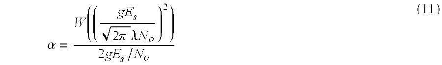
- Equation (10) above is an optimization problem when there is a restriction condition, and it is a typical problem known by Variational Calculus. Therefore, α satisfying Equation (10) is represented as shown in Equation (11):
- Here, W( ) is a known Lambert W function (see R. M. Coreless, G. H. Gonnet, D. E. G. Hare, D. J. Jerrey, and D. E. Knuth, “On The Lambert W Function,” Advances in Computational Mathematics, vol. 5, pp. 329-359, 1996), and is defined in Equation (12) as:
- W(z)e w(z) =Z (12)
- In addition, λ is a constant determined so as to satisfy the restriction condition E[α]=1 of average transmission power. Then, respective antenna weights for minimizing an average bit error rate are calculated as shown in Equation (13):

- Here, α is calculated according to Equation (11).
- In Equation (13),

- are constants that can be previously calculated regardless of channel gains. Therefore, the antenna weight determiner previously calculates the constants, stores the calculated constants in a memory, and calculates antenna weights using channel gains estimated upon every reception of a data symbol and the previously stored constants.
- FIG. 3 is a block diagram illustrating a structure of an
antenna weight determiner 190 according to an embodiment of the present invention. As illustrated, complex conjugate generators 205-1 to 205-M calculate conjugates of channel gains h1, . . . , hM, and power gain acquisition sections 210-1 to 210-M calculate channel power gains by squaring absolute values of the channel gains. Asummer 215 sums up the channel power gains, and areciprocal generator 220 calculates a reciprocal of the sum of the channel power gains. - A
multiplier 225 multiplies the sum of the channel power gains by the previously stored constant
- a
square generator 230 squares an output of themultiplier 225, and a LambertW function generator 235 calculates a Lambert W function output for an output of thesquare generator 230. Amultiplier 240 multiplies the Lambert W function output by the previously storedfunction 
- and a
square root generator 245 calculates a square root for an output of themultiplier 240. Amultiplier 250 multiplies an output of thesquare root generator 245 by an output of thereciprocal generator 220. - Multipliers 255-1 to 255-M calculate weights w1, . . . , WM by multiplying the conjugates of the channel gains by an output of the
multiplier 250. - FIG. 4 is a block diagram illustrating a detailed structure of the power gain acquisition sections 210-1 to 210-M shown in FIG. 3. As illustrated, in an mth power gain acquisition section 210-m, an
absolute calculator 310 calculates an absolute value |hm| of an input channel gain hm, and asquare calculator 320 calculates a square |hm|2 of the absolute value and outputs the calculated square as a channel power gain. - When a radio channel for each transmission antenna is a Rayleigh fading channel, an average bit error rate when determining an antenna weight by the conventional technology is represented as shown in Equation (14):

- An average bit error rate when determining an antenna weight according to the invention is represented as shown in Equation (15):

- Here, λ is a constant that satisfies a restriction condition of average transmission power being equal to 1, shown in Equation (16) below.

- FIG. 5 illustrates average bit error rates calculated using Equation (15) and Equation (16), wherein white points represent average bit error rates according to the conventional technology, while black points represent average bit error rates according to the present invention. As illustrated, compared to the conventional antenna weight determining method, the new antenna weight determining method shows a very low average bit error rate in the same SNR environment. For example, when the number of transmission antennas is M=3, the invention shows performance improvement of about 7.4 dB in terms of an average bit error rate.
- The invention has the following advantages. In the invention, a transmitter optimizes antenna weights according to characteristics of radio channels which vary according to time and space, thereby minimizing an average bit error rate of a closed-loop transmit diversity system. The reduction in an average bit error rate brings about a reduction in average power required in a transmitter, thus contributing to an increase in battery run-time and a decrease in size of a battery of the transmitter. Also, the number of transmission antennas needed to satisfy a required average bit error rate can be reduced, contributing to a decrease in cost required in installing a transmit diversity system.
- While the invention has been shown and described with reference to certain preferred embodiment thereof, it will be understood by those skilled in the art that various changes in form and details may be made therein without departing from the spirit and scope of the invention as defined by the appended claims.
Claims (6)


Applications Claiming Priority (2)
| Application Number | Priority Date | Filing Date | Title |
|---|---|---|---|
| KR1020030038390A KR100950640B1 (en) | 2003-06-13 | 2003-06-13 | Method and apparatus for determining antenna weights in close-loop transmit diversity system |
| KR38390/2003 | 2003-06-13 |
Publications (2)
| Publication Number | Publication Date |
|---|---|
| US20040252797A1 true US20040252797A1 (en) | 2004-12-16 |
| US7391817B2 US7391817B2 (en) | 2008-06-24 |
Family
ID=33297398
Family Applications (1)
| Application Number | Title | Priority Date | Filing Date |
|---|---|---|---|
| US10/858,617 Active 2026-03-07 US7391817B2 (en) | 2003-06-13 | 2004-06-02 | Method and apparatus for determining antenna weight in a closed-loop transmit diversity system |
Country Status (4)
| Country | Link |
|---|---|
| US (1) | US7391817B2 (en) |
| EP (1) | EP1487133B1 (en) |
| KR (1) | KR100950640B1 (en) |
| DE (1) | DE602004021452D1 (en) |
Cited By (5)
| Publication number | Priority date | Publication date | Assignee | Title |
|---|---|---|---|---|
| WO2008057471A1 (en) * | 2006-11-06 | 2008-05-15 | Magnolia Broadband Inc. | Modifying a signal by controlling transmit diversity parameters |
| US20080160922A1 (en) * | 2006-12-27 | 2008-07-03 | Wei Sun | Method, system and apparatus for transmit diversity control |
| US20100166095A1 (en) * | 2008-12-30 | 2010-07-01 | Snu R&Db Foundation | Cooperative diversity method and cooperative diversity system using opportunistic relaying |
| US20100234011A1 (en) * | 2006-08-22 | 2010-09-16 | Koninklijke Philips Electronics N.V. | Methods for transmitting data in a mobile system and radio stations therefor |
| US8812045B2 (en) | 2009-03-09 | 2014-08-19 | Lg Electronics Inc. | Method for controlling transmission power in a multi-antenna wireless communication system |
Families Citing this family (4)
| Publication number | Priority date | Publication date | Assignee | Title |
|---|---|---|---|---|
| US7877071B2 (en) * | 2007-08-01 | 2011-01-25 | Broadcom Corporation | Unified STTD/CLTD dedicated pilot processing |
| KR100958917B1 (en) * | 2008-06-10 | 2010-05-19 | 충북대학교 산학협력단 | A fast index search algorithm for codebook-based beamforming scheme |
| CN102938664B (en) * | 2011-08-16 | 2017-12-15 | 中兴通讯股份有限公司 | A kind of method and system for controlling uplink closed loop transmitting diversity |
| US9209876B2 (en) * | 2011-12-30 | 2015-12-08 | Broadcom Corporation | Adaptive transmit beamforming |
Citations (6)
| Publication number | Priority date | Publication date | Assignee | Title |
|---|---|---|---|---|
| US20030017835A1 (en) * | 2001-07-19 | 2003-01-23 | Itshak Bergel | Deriving a more accurate estimate from prediction data in closed loop transmit diversity modes |
| US20030035491A1 (en) * | 2001-05-11 | 2003-02-20 | Walton Jay R. | Method and apparatus for processing data in a multiple-input multiple-output (MIMO) communication system utilizing channel state information |
| US20050020237A1 (en) * | 2003-07-16 | 2005-01-27 | Angeliki Alexiou | Method and apparatus for transmitting signals in a multi-antenna mobile communications system that compensates for channel variations |
| US6865237B1 (en) * | 2000-02-22 | 2005-03-08 | Nokia Mobile Phones Limited | Method and system for digital signal transmission |
| US6922549B2 (en) * | 2003-10-31 | 2005-07-26 | Cisco Technology, Inc. | Error vector magnitude selection diversity metric for OFDM |
| US7206554B1 (en) * | 2002-06-28 | 2007-04-17 | Arraycomm Llc | Transmit diversity with formed beams in a wireless communications system using a common pilot channel |
Family Cites Families (4)
| Publication number | Priority date | Publication date | Assignee | Title |
|---|---|---|---|---|
| US6888809B1 (en) * | 2000-01-13 | 2005-05-03 | Lucent Technologies Inc. | Space-time processing for multiple-input, multiple-output, wireless systems |
| KR100378357B1 (en) * | 2001-05-07 | 2003-03-29 | 삼성전자주식회사 | Radio communication appratus and method having more channel capacity and less feedback information |
| DE10131946B4 (en) | 2001-07-02 | 2014-10-16 | Siemens Aktiengesellschaft | Method for operating a mobile radio communication system and stations therefor |
| CN1161907C (en) | 2001-07-20 | 2004-08-11 | 华为技术有限公司 | Downstream feedback multiple-antenna emitting method and device for radio communication system |
-
2003
- 2003-06-13 KR KR1020030038390A patent/KR100950640B1/en not_active IP Right Cessation
-
2004
- 2004-06-02 US US10/858,617 patent/US7391817B2/en active Active
- 2004-06-14 DE DE602004021452T patent/DE602004021452D1/en active Active
- 2004-06-14 EP EP04013902A patent/EP1487133B1/en not_active Expired - Fee Related
Patent Citations (6)
| Publication number | Priority date | Publication date | Assignee | Title |
|---|---|---|---|---|
| US6865237B1 (en) * | 2000-02-22 | 2005-03-08 | Nokia Mobile Phones Limited | Method and system for digital signal transmission |
| US20030035491A1 (en) * | 2001-05-11 | 2003-02-20 | Walton Jay R. | Method and apparatus for processing data in a multiple-input multiple-output (MIMO) communication system utilizing channel state information |
| US20030017835A1 (en) * | 2001-07-19 | 2003-01-23 | Itshak Bergel | Deriving a more accurate estimate from prediction data in closed loop transmit diversity modes |
| US7206554B1 (en) * | 2002-06-28 | 2007-04-17 | Arraycomm Llc | Transmit diversity with formed beams in a wireless communications system using a common pilot channel |
| US20050020237A1 (en) * | 2003-07-16 | 2005-01-27 | Angeliki Alexiou | Method and apparatus for transmitting signals in a multi-antenna mobile communications system that compensates for channel variations |
| US6922549B2 (en) * | 2003-10-31 | 2005-07-26 | Cisco Technology, Inc. | Error vector magnitude selection diversity metric for OFDM |
Cited By (12)
| Publication number | Priority date | Publication date | Assignee | Title |
|---|---|---|---|---|
| US20100234011A1 (en) * | 2006-08-22 | 2010-09-16 | Koninklijke Philips Electronics N.V. | Methods for transmitting data in a mobile system and radio stations therefor |
| US8675508B2 (en) * | 2006-08-22 | 2014-03-18 | Koninklijke Philips N.V. | Methods for transmitting data in a mobile system and radio stations therefor |
| US10205579B2 (en) | 2006-08-22 | 2019-02-12 | Koninklijke Philips N.V. | Methods for transmitting data in a mobile system and radio stations therefor |
| WO2008057471A1 (en) * | 2006-11-06 | 2008-05-15 | Magnolia Broadband Inc. | Modifying a signal by controlling transmit diversity parameters |
| US20080123775A1 (en) * | 2006-11-06 | 2008-05-29 | Eduardo Abreu | Modifying a signal by controlling transmit diversity parameters |
| US8150441B2 (en) | 2006-11-06 | 2012-04-03 | Magnolia Broadband Inc. | Modifying a signal by controlling transmit diversity parameters |
| US8351976B2 (en) | 2006-11-06 | 2013-01-08 | Google Inc. | Modifying a signal by controlling transmit diversity parameters |
| US8630678B2 (en) | 2006-11-06 | 2014-01-14 | Google Inc. | Modifying a signal by controlling transmit diversity parameters |
| US20080160922A1 (en) * | 2006-12-27 | 2008-07-03 | Wei Sun | Method, system and apparatus for transmit diversity control |
| US8027374B2 (en) | 2006-12-27 | 2011-09-27 | Magnolia Broadband Inc. | Method, system and apparatus for transmit diversity control |
| US20100166095A1 (en) * | 2008-12-30 | 2010-07-01 | Snu R&Db Foundation | Cooperative diversity method and cooperative diversity system using opportunistic relaying |
| US8812045B2 (en) | 2009-03-09 | 2014-08-19 | Lg Electronics Inc. | Method for controlling transmission power in a multi-antenna wireless communication system |
Also Published As
| Publication number | Publication date |
|---|---|
| DE602004021452D1 (en) | 2009-07-23 |
| KR100950640B1 (en) | 2010-04-01 |
| EP1487133A1 (en) | 2004-12-15 |
| EP1487133B1 (en) | 2009-06-10 |
| US7391817B2 (en) | 2008-06-24 |
| KR20040107787A (en) | 2004-12-23 |
Similar Documents
| Publication | Publication Date | Title |
|---|---|---|
| CN1921325B (en) | System and method for received signal prediction in wireless communications system | |
| US8054905B2 (en) | Method of measuring transmit quality in a closed loop diversity communication system | |
| CN100474786C (en) | System and method for adjusting combiner weights using an adaptive algorithm in a wireless communications system | |
| US6766144B2 (en) | Method and apparatus for estimating optimum weight of closed loop transmit deversity for mobile communication | |
| US6892059B1 (en) | Closed-loop transmitting antenna diversity method, base station apparatus and mobile station apparatus therefor, in a next generation mobile telecommunications system | |
| US20020058505A1 (en) | Rain attenuation compensation method using adaptive transmission technique and system using the same | |
| US20040014501A1 (en) | Radio communication system using adaptive array antenna | |
| US8462701B2 (en) | System and method for received channel power indicator (RCPI) measurement | |
| EP1931060A1 (en) | Wireless communication system, base station apparatus, mobile station apparatus, and macro-diversity selecting method | |
| US7230928B2 (en) | Data transfer method | |
| EP1456966B1 (en) | Method and apparatus for quality measure target value based site selecton diversity | |
| US20070086541A1 (en) | Apparatus and method for processing LLR for error correction code in a mobile communication system | |
| US20050135497A1 (en) | Adaptive transmitting and receiving device and method in wireless communication system using frequency division duplexing | |
| US20020167923A1 (en) | Method and apparatus for estimating channel characteristics using pilot and non-pilot data | |
| CN1455473A (en) | Self-adaptive beam-formation apparatus and method | |
| CN1345136A (en) | Phase estimating method for diversity system arial of wide-band CDMA closed-loop transmitter arial | |
| US7391817B2 (en) | Method and apparatus for determining antenna weight in a closed-loop transmit diversity system | |
| US7206353B2 (en) | Mobile communication apparatus including an antenna array and mobile communication method | |
| US20040132494A1 (en) | Communication method | |
| US7065149B2 (en) | Transmitter, the method of the same and communication system | |
| CN100356704C (en) | Method for compensating frequency offset in wireless mobile communication system | |
| US20070233474A1 (en) | Apparatus and method for quantization in digital communication system | |
| US20080031390A1 (en) | Antenna diversity receiver | |
| US7088289B1 (en) | Antenna adaptation method, communication terminal, device; module and computer program product | |
| US20020160803A1 (en) | Power calculation method of a radio communication system and an apparatus thereof |
Legal Events
| Date | Code | Title | Description |
|---|---|---|---|
| AS | Assignment |
Owner name: SAMSUNG ELECTRONICS CO., LTD., KOREA, REPUBLIC OF Free format text: ASSIGNMENT OF ASSIGNORS INTEREST;ASSIGNOR:LEE, YE-HOON;REEL/FRAME:015422/0702 Effective date: 20040408 |
|
| STCF | Information on status: patent grant |
Free format text: PATENTED CASE |
|
| FEPP | Fee payment procedure |
Free format text: PAYOR NUMBER ASSIGNED (ORIGINAL EVENT CODE: ASPN); ENTITY STATUS OF PATENT OWNER: LARGE ENTITY |
|
| FEPP | Fee payment procedure |
Free format text: PAYER NUMBER DE-ASSIGNED (ORIGINAL EVENT CODE: RMPN); ENTITY STATUS OF PATENT OWNER: LARGE ENTITY Free format text: PAYOR NUMBER ASSIGNED (ORIGINAL EVENT CODE: ASPN); ENTITY STATUS OF PATENT OWNER: LARGE ENTITY |
|
| FPAY | Fee payment |
Year of fee payment: 4 |
|
| FPAY | Fee payment |
Year of fee payment: 8 |
|
| MAFP | Maintenance fee payment |
Free format text: PAYMENT OF MAINTENANCE FEE, 12TH YEAR, LARGE ENTITY (ORIGINAL EVENT CODE: M1553); ENTITY STATUS OF PATENT OWNER: LARGE ENTITY Year of fee payment: 12 |